Embed Size (px)
Citation preview

doi: 10.1016/j.promfg.2016.08.055
Machining and Metrology of a Chalcogenide Glass Freeform Lens Pair
John R. Troutman1, Daniel L. Barnhardt1, Jason A. Shultz1, Joseph D. Owen1, Scott DeFisher2, Matthew A. Davies1, Thomas J. Suleski1
1University of North Carolina at Charlotte, Charlotte, NC, USA 2OptiPro Systems, Ontario, NY, USA
Abstract Slow tool servo remains a preferred method for ultraprecision manufacture of freeform optics with millimeter-scale departures from an axisymmetric surface. A methodology has been developed for pre-process mapping of, and compensation for, predictable error sources such as tool waviness and machine misalignment, reducing necessity for typical post-process workpiece error correction procedures. This methodology is implemented for manufacture of a chalcogenide glass freeform lens pair for a variable-focus thermal imaging application. Process development, part metrology, and system functional testing are presented. Keywords: slow tool servo, Alvarez lens, chalcogenide, diamond turning
1 Introduction Optical components have traditionally been based upon combinations of planar and spherical
surfaces, primarily due to the ease of manufacture and testing. Advances in capability of design and simulation software have facilitated a revolution in optical system design (Thompson & Rolland, 2012) through the use of freeform optical surfaces of arbitrary form. When leveraged in both imaging and non-imaging system design, these often non-axisymmetric surfaces provide distinct advantages over traditional designs. Several traditional surfaces can be combined into a single composite, allowing reduction in component count, system mass, complexity, and eliminating many assembly-based sources of misalignment. Freeform surfaces can be used for aberration correction and also to enable novel function, such as in the case of the variable-focus Alvarez lens (Alvarez, 1967). Enabling the manufacture of freeform optics allows further design freedom, such as inclusion of integrated alignment, mounting, and fiducial features on an optic, transferring the accuracy of an ultraprecision machine tool directly to assembly tolerances.
Procedia Manufacturing
Volume 5, 2016, Pages 669–683
44th Proceedings of the North American ManufacturingResearch Institution of SME http://www.sme.org/namrc
Selection and peer-review under responsibility of the Scientific Programme Committee of NAMRI/SMEc© The Authors. Published by Elsevier B.V.
669

While there are many challenges associated with the manufacture and metrology of freeform surfaces, contemporary ultraprecision machine tools enable direct machining of such optics with form accuracies on order of ±200 nm and surface finishes on order of 2 nm. This is well suited for infrared (IR) applications where finish and form tolerances are less stringent. Many examples in the literature demonstrate that under appropriate cutting conditions, brittle optical materials can be machined in a ductile-dominated manner, leaving behind a fracture-free surface of optical quality. IR materials such as silicon and germanium can be processed by ultraprecision diamond turning (Ogura & Okizaki, 2000) (Nakasuji, et al., 1990), milling (Smilie, et al., 2011) (Rusnaldy & Kim, 2007), and grinding (Bifano, et al., 1991). For materials which are not as readily machined in a ductile-dominated manner, similar surface finishes and form accuracies (Wolfs, et al., 2015) (Fess, et al., 2015) are achievable using sub-aperture polishing of ground blanks.
When working to sub-micrometer tolerances, workpiece errors can arise from many sources, such as tool shape error, tool deflection, machine tool axis misalignment, thermal effects, and environmental vibration. In many cases, producing an optic to specification requires machining, on-machine part measurement, generation of a compensated toolpath using on-machine workpiece error measurement and correction software, then re-machining. However, as described in (Owen & Davies, 2015), the use of appropriate setup artifacts can enable pre-process mapping of predictable error sources and generation of compensated toolpaths, obviating workpiece measurement and error correction procedures which are time-consuming and must be done on a per workpiece basis.
In this paper, a methodology for tool selection and toolpath generation is presented for the slow tool servo machining technique. The pre-process mapping of tool and machine error sources and subsequent manufacturing, functional testing, and metrology of a chalcogenide glass freeform variable-focus lens pair based upon the Alvarez design is described. Once predictable errors from the machine and tool are mapped, the same tool can be used to manufacture other optics without additional measurements.
2 Process Development Ultraprecision machine tools are commonly developed from a fundamental building block, the
diamond turning lathe, which having sufficient accuracy and stiffness to do so, has been used for several decades in the production of optical quality, rotationally symmetric surfaces. Addition of a position-controlled rotary axis, often via a configuration in which the main spindle can be switched between speed-controlled and position-controlled modes, to a two-axis diamond turning lathe (Bryan, 2003) allows coordinated-axis slow tool servo (STS) machining of freeform optics with mild surface departures. STS operations typically occur at rotational rates from 100 to 2000 rpm, limited by the machine tool’s axis dynamics, controller bandwidth, and the required tool stroke. While the tool is mounted directly to the machine axes in the STS configuration, the tool can also be mounted to an auxiliary-driven piezoelectric or voice coil actuator of much lower mass and inertia in a fast tool servo (FTS) configuration, allowing tool motion at frequencies up to 1 kHz at the expense of stroke, typically limited to several micrometers at such frequencies. Contemporary ultraprecision machining centers are often available with five (three linear- and two rotary-controlled) or more axes and high speed (up to 60,000 rpm) secondary spindles which, with appropriate tooling, allow multi-axis diamond milling and grinding of nearly arbitrary surfaces. While the geometrical capabilities of diamond milling are unmatched by turning-based processes and the production speed of FTS is advantageous under certain circumstances, due to setup simplicity and modest additional equipment requirements, the STS process often remains the preferred method of machining freeform surfaces with millimeter-scale departures from an axisymmetric surface.
For an STS operation as described in this paper, the linear axes of a diamond turning lathe and the rotary-controlled main spindle form an X-Z-C axis system, as illustrated in Figure 1. Such an
Machining and Metrology of a Chalcogenide Glass Freeform Lens Pair Troutman et al.
670

arrangement suggests expression of part form in right cylindrical coordinates. In this configuration, the round-nosed tool is oriented such that the entire cutting edge lies in the X-Z plane, and such that for any point on the part, cutting action occurs on the rounded portion of the tool nose. Typical ultraprecision machining operations are performed using single crystal diamond (SCD) tools with a nose radius on the order of several millimeters.
Conventional macroscale components are easily-represented in modern CAD/CAM packages by primitive solids and spline-based surfaces. However, optical surfaces are generally defined by an equation or prescription, and cannot be represented in a like manner without introducing unacceptable errors due to approximation inherent to fitting algorithms used in such software. These software packages, which also assume perfect tool shape and machine axis orthogonality, are therefore inappropriate for toolpath generation for ultraprecision operations which often specify form tolerances of ±200 nm or tighter. At these tolerance levels, successful optical manufacture often requires compensation for tool shape deviations and machine axis alignment. Therefore, an analytical formulation for toolpath generation is necessary. While use of any coding environment is feasible, the work presented in this paper was performed using MATLAB .
Figure 1: Slow tool servo machine configuration and part coordinate origin.
2.1 Tool Selection Criteria For an optical surface described in the right cylindrical coordinates system shown in Figure 1, the
position of any point on the surface in those coordinates can be expressed according to Eq. 1. For surface prescriptions not expressed in these coordinates, an appropriate parameterization may be required. Slope and curvature analysis must be applied to select an appropriate tool geometry which will prevent collisions between the tool and workpiece. The nose radius of the tool, Rct, must be less than the minimum radius of curvature in any individual ρ–z plane on the part, as stated in Eq. 2. Similarly, as stated in Eq. 3, the tool clearance angle, βt, must be greater than the maximum part slope in any individual ϕ-z plane. While large negative rake angles are preferred for some brittle materials, many metals and glasses can be satisfactorily machined using zero rake tools.
(1)
Machining and Metrology of a Chalcogenide Glass Freeform Lens Pair Troutman et al.
671

(2)
(3)
2.2 Error Mapping and Toolpath Generation For an ideal, perfectly-shaped tool, cutting action occurs at a location along the tool nose where the
local tool and part slope are matched, as shown in Figure 2. However, in practice, the tool is not ideally-shaped, and has edge waviness, which can be described as a radius variation, dRct, which varies with tool sweep angle, θ. For typical diamond tools, these shape errors, which will produce slope-dependent errors on a machined part, can have magnitudes from 50 nm to several micrometers depending on specified level of waviness control.
Figure 2: Tool waviness and cutting zone.
Initial tool setup using an on-machine microscope and known offsets from the spindle centerline to the camera focus position are suitable for defining tool height and tip position with respect to the spindle centerline to ±10 μm or better. If the cutting edge is above the spindle centerline, a cone-shaped center defect will be present on a machined part, while a tool which is too low will result in a cylindrical defect. Face-machining of an artifact, measurement of the center defect, and subsequent tool height adjustment are sufficient to refine tool height within ±1 μm of the spindle centerline. Similarly, by plunging the tool into the artifact and measuring the diameter of the resulting toric recess, tool position along the X-direction can also be set to ±1 μm or better. Residual tool offset errors, δx and δz, are shown in Figure 1 and are defined as the difference between true and indicated tool position relative to the spindle centerline. These will be apparent on the final optic as slope dependent error convolved with tool edge waviness effects. Though correctable with offset adjustments at the controller, the resulting slope-dependent error, measured along the z-coordinate of the part, due to tool offset error is described by Eq. 4a-b for the usual case of Rct δx. Similarly, deviations from C-X perpendicularity, X-Z perpendicularity, or C-Z parallelism will combine to form an effective X-Z angular misalignment, δxz,, producting a cone-shaped error on the optic.
The use of spherical artifacts for pre-process mapping of tool and machine errors for milling operations is described in (Owen & Davies, 2015). Due to process geometry, milling and turning processes typically only make use of a single side of the diamond tool (all points on the part correspond to tool sweep of identical sign), but STS operations quite often use a portion of both sides of the tool. While it is technically feasible to map both sides of a diamond tool using two diamond-
Machining and Metrology of a Chalcogenide Glass Freeform Lens Pair Troutman et al.
672
turned artifacts, precision air bearing spindles often exhibit different error motions in position control mode than during free rotation, thus, for the STS process, it is desirable to map the axis alignment effects and tool errors using an artifact also machined by STS. Among the viable artifact types which are easily measured, for example by Fizeau interferometry, are tilted flats and decentered spheres.
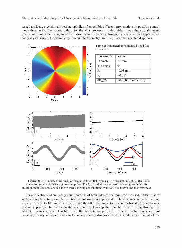
Table 1: Parameters for simulated tilted flat error map.
Parameter Value
Diameter 12 mm
Tilt angle 3°
δx -0.03 mm
δxz +0.01°
dRct(θ) +0.0005[mm/deg2] θ2
Figure 3: (a) Simulated error map of machined tilted flat, with a single orientation feature. (b) Radial
slices and (c) circular slices of error map from Fig 2, (d) radial slice at φ=0° indicating machine axis misalignment, (e) circular slice at ρ=3 mm, showing contributions from tool offset error and tool waviness.
For applications where nearly equal portions of both sides of the tool nose are used, a tilted flat of sufficient angle to fully sample the utilized tool sweep is appropriate. The clearance angle of the tool, usually from 5° to 10°, must be greater than the tilted flat angle to prevent tool-workpiece collisions, placing a practical limitation on the maximum tool sweep that can be mapped using this type of artifact. However, when feasible, tilted flat artifacts are preferred, because machine axis and tool errors are easily separated and can be independently discerned from a single measurement of the
Machining and Metrology of a Chalcogenide Glass Freeform Lens Pair Troutman et al.
673

artifact using a reference flat. A small flat along one side is sufficient for aligning the measurement into the artifact coordinate system. Radial slices of the artifact reveal axis misalignment errors, while circular slices at a constant radius reveal slope dependent error tool errors. Figure 3(a) presents a simulated error map for a tilted flat of the form z(ρ,ϕ) = ρcosϕ with error sources as described in Table 1. Many radial and circular slices of this measurement are shown in Figure 3(b-c), while selected slices are shown in Figure 3(d-e). Separation of tool and machine error sources is evident, as is the contribution of tool offset error and waviness to total slope dependent error.
Table 2: Parameters for simulated decentered sphere error map.
Parameter Value
Diameter 25 mm
Radius of curvature 40 mm
Radial decenter, ρ0 5 mm
Angular decenter, ϕ0 30°
Depth of recess 1 mm
δx +0.02 mm
δxz +0.10°
dRct(θ) -0.0001 [mm/deg2] θ2
Figure 4: (a) Simulated error map of machined concave decentered sphere with two orientation features.
(b) Radial slices and (c) circular slices of composite error map, (d) radial slices of flat portion of artifact indicating machine axis misalignment, (e) residual slope dependent errors after removing trends due to machine
sources, showing contributions of tool waviness and offset error.
For applications where a large portion of one side of the tool is used, a decentered sphere can be used to map machine axis and tool errors with less stringent constraint on tool clearance angle. Beginning with a cylindrical workpiece concentric to the rotary axis, the STS process is used to cut a
Machining and Metrology of a Chalcogenide Glass Freeform Lens Pair Troutman et al.
674

concave spherical recess which has a center point at some (ρ0, ϕ0) location, offset from the axis centerline. The remainder of the artifact face is also machined flat in STS mode. Although often the only feasible artifact, discernment of error sources is less straightforward than for a tilted flat. Two measurements are necessary to fully measure the artifact and separate tool and machine error sources. The flat portion of the artifact face is measured using a reference flat, while a reference sphere is necessary to measure the concave recess. Further, at least two alignment features are necessary to orient the two measurements with respect to one another and with the artifact coordinate system. Once properly registered, machine axis misalignment can be determined from the measurement of the flat portion of the artifact, which can be removed from that of the spherical portion, isolating slope dependent tool errors. Figure 4(a) presents a simulated composite error map for the decentered concave sphere described in Table 2. Many radial and circular slices of the composite measurement are shown in Figure 4(b-c), while radial slices of only the flat portion are shown in Fig 5c. After determining machine axis errors and removing this trend from the measurement of the spherical portion, slope dependent errors are isolated in Figure 4(d-e), showing contributions from both tool offset error and tool waviness effects.
Once an artifact has been machined using an uncompensated toolpath and measured, tool offset errors are identified and necessary controller offset corrections are applied. If the artifact is of the same material as the intended optic and is machined using identical depth of cut and stepover per revolution, tool deflection will also result in a slope-dependent error which is convolved with tool waviness. Remaining slope-dependent errors can typically be well-represented as a function of part slope or tool sweep angle using a high-order polynomial, linear or cubic spline, or any other representation which yields an acceptable fit to the measured artifact. The artifact is then re-machined using an appropriately compensated toolpath and re-measured. Subsequent optics machined using identical waviness and alignment compensations are then expected to display similar error magnitudes as the re-machined artifact.
(4a)
(4b)
Toolpath generation begins with the creation of a list of (ρ,ϕ,z) points on the surface to be cut, which can be spaced by equal chord lengths or equal angular increments. The surface equation is evaluated at each point along the toolpath spiral, and each surface point is then offset by the tool radius in the direction of the component of the outward normal vector which lay in the ρ-z plane, as described in Eq. 5a-6. If slope-dependent errors are known from analysis of a setup artifact, they may be compensated for during this step. After tool nose radius compensation, compensation for machine axis misalignment, if known and desired, can be applied using Eq. 7.
(5a)
(5b)
(6)
(7)
Machining and Metrology of a Chalcogenide Glass Freeform Lens Pair Troutman et al.
675

3 Design and Manufacturing The original Alvarez lens as documented in the patent (Alvarez, 1967) is described by two
identical cubic polynomial surfaces which are represented in rectilinear coordinates by Eq. 8, where A and C are an Alvarez constant and a base height shift, respectively. When these surfaces are placed opposing each other with collocated origins, the composite thickness of the optical device is constant, equivalent to a planar element with zero optical power. If a small lateral shearing displacement, d, is introduced between the surfaces along the x-axis, as illustrated in Figure 5, the composite is equivalent to a plano-spherical element which can have either positive or negative optical power, depending on shearing direction. The effective focal length of such a physical system can be calculated from Eq. 9, where n is the index of refraction of the lens material.
(8)
(9)
While an Alvarez pair described by Eq. 9 has zero optical power at zero shear, many adjustable focus systems require focal displacement about a nominal signed value. Such function is feasible by using only a small subset of the working range of a cubic Alvarez pair, yet requires surfaces with unnecessarily large peak to valley heights and material removal requirements. To minimize surface height and improve manufacturability, a freeform lens pair of 15 mm aperture diameter was designed for a thermal imaging application using 14th order polynomial surfaces, such that at zero shear, the system focal length is 77 mm and is adjustable from of 38.5 mm to positive infinity over a shear of ±1.8 mm. The lens pair was constructed from 25 mm diameter discs of As40Se60 (trade name IRG 26) chalcogenide glass.
Figure 5: Composite thickness of displaced cubic Alvarez surfaces.
The cutting mechanics experiments referenced and machining described hereafter were performed using a Moore Nanotechnology 350FG ultraprecision machining center, which is located in a vibration- and acoustically-isolated laboratory with temperature control to ±0.1°C. This machine can perform conventional diamond turning and STS operations, and is equipped with five position-
Machining and Metrology of a Chalcogenide Glass Freeform Lens Pair Troutman et al.
676

controlled axes and an auxiliary high speed micro-machining spindle. It is capable of multi-axis ultraprecision grinding and milling operations, and is equipped with both mist and flood coolant systems which deliver mineral oil to the cutting zone as desired.
3.1 Machining Parameter Selection Extensive cutting experiments in IRG 26 chalcogenide are presented in (Troutman, et al., 2015)
(Owen, et al., 2015). From orthogonal turning investigations using zero-rake tooling, it is known that this material does not cause appreciable tool wear, and exhibits a change in material removal mechanism from a ductile, plastic deformation-dominated mode to a brittle, cracking-dominated mode when undeformed chip thickness exceeds a value of approximately 600 nm at any location along the tool nose. To examine the effect of varying rake angle on cutting behavior, a sinusoidal test specimen described by Eq. 10 was machined using the selected tool and appropriate cutting parameters to verify that cutting remained in the ductile-dominated cutting regime for an effective rake angle range of ±3°. SWLI examination of the surface was performed at locations corresponding to effective rake extrema, as shown in Figure 6. Over the range of rake angles sampled, no fracture or surface damage was apparent, compared to a small reference band machined in the brittle-dominated mode using more aggressive parameters.
(10)
Figure 6: ±3° rake plate specimen from Eq. 11. Clockwise from top-left: specimen; SWLI of -3°, 0°, +3°
effective rake region, and of brittle-dominated band for comparison.
Slope analysis from Eq. 2-3 of the surface to be machined indicated a maximum permissible tool nose radius of 42 mm, a minimum required clearance angle of 1.5°, and that machining this part would sweep over θ = -1° to +3° with respect to Figure 2. A controlled-waviness tool with nose radius of 1.5 mm, 7° clearance, and 0° top rake was selected for this machining process. A target, though optimistic, 20 nm part error stipulated a 13 μm toolpath chord length between points, corresponding to a 0.1° angular increment at the outer edge of the 15 mm diameter aperture. From operator experience and previous results, semi-aggressive rough machining parameters were chosen to increase material
Machining and Metrology of a Chalcogenide Glass Freeform Lens Pair Troutman et al.
677
removal rate by cutting in the brittle-dominated regime while remaining below the onset of catastrophic material failure. For finish machining, remaining within the ductile-dominated cutting regime to leave a final surface of optical quality required a toolpath stepover of 6.5 μm per revolution using the selected tool at a depth of cut of 7.5 μm. However, a target surface finish of 1.3 nm Ra further limited the finish cut to a smaller stepover of 2 μm/rev. The selected machining parameters are summarized in Table 3.
3.2 Manufacturing of Optics To enable pre-process mapping of tool waviness and machine axis misalignment and eliminate the
requirement of post-process workpiece measurement and error correction procedures, a 12 mm diameter, 3° tilted flat was used to determine tool error properties: waviness and offset. The artifact was first machined in OFHC copper using an uncompensated toolpath, assuming a perfectly circular tool and zero offset errors. The resulting artifact, which had an orientation flat on one side, was measured, using a Zygo VeriFIRE ATZ, indicating a peak to valley error of 140 nm. While this form accuracy would have been sufficient for the intended 3-5 μm IR application, a slight correction was performed to demonstrate this methodology. Although a controlled waviness tool was used, and therefore no correctable waviness errors could be discerned, a slight cone-shaped error trend due to spindle axis misalignment was observed. This was compensated for and a new tilted flat was machined. This artifact had a reduced peak to valley error of 110 nm. Measurements of both uncompensated and compensated tilted flats are shown in Figure 7.
Table 3: Selected machining parameters for IRG 26 freeform lens pair.
Parameter Roughing Finishing Depth of cut 25 μm 7.5 μm Stepover per revolution 25 μm 2.0 μm Maximum undeformed chip thickness 4.5 μm 0.2 μm Rotational rate 16.66 rpm 16.66 rpm Coolant method (mineral oil) Mist Flood
Toolpath generation for the freeform lens pair was performed in MATLAB from Eq. 6-8 using
compensation for the tool and spindle errors determined from the tilted flat. Each IRG 26 workpiece was mounted on a vacuum chuck and machined to leave a 15 mm diameter pedestal above a 1.5 mm thick, 25 mm diameter base. After allowing 12 hours for the machine to reach thermal equilibrium, the functional surface was machined using 15 rough machining passes and 4 finishing passes to remove any resulting surface damage, in accordance with Table 3. After machining of the optical surfaces, mounting slots and an alignment flat were machined using a solid carbide endmill, resulting in slight edge chipping around these features that did not affect the clear aperture of the optic. A segment of the generated toolpath and the final optics, which were expected to have similar form errors to the compensated tilted flat, are shown in Figure 8.
Machining and Metrology of a Chalcogenide Glass Freeform Lens Pair Troutman et al.
678

Figure 7: Uncompensated (left) and compensated (right) tilted flat setup artifacts.
Figure 8: Toolpath segment and machined freeform variable-focus lens pair.
4 Metrology and Testing
4.1 Metrology of Optical Surface The entire optical surface was examined using a Zygo ZeGage Plus coherence scanning white light
interferometer (SWLI) which acquired 121 surface maps using a 5x Michelson objective with 1.67 mm square field of view. The surface maps overlapped by 30% and were stitched together using Zygo Mx software to form a composite map of the surface. Data voids existed in regions where local part slope exceeded the ±2.5° acceptance angle of the objective. The measured and target points were registered into a common coordinate frame using a least squares minimization routine. When compared to the optical prescription, the peak to valley form error was 1.726 μm with a standard deviation of 0.100 μm. Additional evaluation at 20x magnification indicated surface finish of 6 nm rms at six locations on the part.
Further surface metrology was performed using an OptoPro UltraSurf five-axis noncontact measurement system with a chromatic confocal probe. This probe, which uses a visible light source
Machining and Metrology of a Chalcogenide Glass Freeform Lens Pair Troutman et al.
679

and has a ±25° acceptance angle, was an appropriate choice for metrology of this mildly-sloped IRG 26 freeform, which is opaque at wavelengths below 1.1 μm. Single-point measurements were taken over the entire aperture at a spacing of approximately 50 μm, registered to the target points, and a 6x6 pixel moving average filter was applied. When compared to the surface prescription, part peak to valley form error of 1.660 μm with a standard deviation of 0.256 μm was indicated. The results of this measurement are compared to those of the stitched SWLI measurement in Figure 9.
While the uncertainties of these area-based and point-based metrology techniques are difficult to estimate, both measurements exhibit similar error shape and magnitudes. Although both techniques suggest similar part form, indicated errors may have similar uncertainties due to misalignment inherent to the point cloud registration. Although these metrology systems differ, misalignment errors are correlated, as the same algorithm for point cloud registration was used for both measurements. The effect of misalignment could be reduced if fiducials, for example three concave spherical recesses at known locations, were machined outside the clear aperture but concurrent with the manufacture of the functional surface. Although these form deviations of approximately ±0.5 waves at 2 μm exceed the levels predicted by the tilted flat setup artifact used for pre-process error mapping, they remain acceptable for the intended application. While these metrology results indicate an upper bound on form error, additional work is necessary reduce the uncertainty in the measurement procedure before the true machining errors can be quantified. An evaluation of instrument-related error sources, for example slope-dependent errors as determined using self-calibration techniques like the random ball test (Zhou, et al., 2013) as well as further analysis of the point cloud registration algorithm would assist with identification of error and uncertainty sources.
Figure 9: Stitched SWLI error map (left), OptiPro Ultrasurf error map (right).
4.2 Functional Performance Evaluation Functional testing of the variable-focus system was conducted after manufacturing and metrology.
The optics were each mounted to three-axis optical stages using custom-built brackets and mounting
Machining and Metrology of a Chalcogenide Glass Freeform Lens Pair Troutman et al.
680

rings. The translation stages were mounted, as shown in Figure 10, to a fixturing plate atop a Newport ILS linear motion stage, which was placed in front of an Indigo Phoenix thermal imaging camera. This nitrogen-cooled camera has 30 μm square pixels and detects wavelengths from 3 μm to 5 μm. The setup allowed a controlled shear between the two optics to be introduced producing the change in focal length predicted by Eq. 10. A hot plate, used as a thermal radiation source, was located along the optical axis of the camera, approximately 2.5 m away, outside the field of view of the shown photograph. After assembling with a 400 μm gap between lenses and performing preliminary alignment, the entire lens assembly was translated on the linear motion stage along the optical axis of the camera. At each value of the shear the optic was translated until the best focus position was determined. The process was repeated three times for shear displacements from -0.8 mm to +1.0 mm in 0.1 mm increments.
Figure 10: Experimental apparatus for functional testing of variable-focus freeform lens pair.
Figure 11: Freeform variable-focus lens pair focal length change with lateral shear.
Performance of the system clearly demonstrated the variable-focus principle. Focal length of the STS-machined system is compared in Figure 11 to theoretical values as well as results from repeating this functional testing procedure using identical optics machined by a freeform milling operation.
Machining and Metrology of a Chalcogenide Glass Freeform Lens Pair Troutman et al.
681

Selected images of the hot plate are shown as well. Over the majority of the test range, both theoretical and milled focal lengths lie within the measurement uncertainty. For large negative shear displacements, deviations from predicted values are larger due to increased difficulty in precisely finding optimum focus due to increased depth of field and reduced magnification at these points.
5 Discussion Machining parameters for the manufacture of two IRG 26 (As40Se60 chalcogenide glass) freeform
optics for a variable-focus thermal imaging system were chosen from the results of simplified cutting experiments. Toolpath was generated analytically from the surface prescription using MATLAB software which is capable of compensating for tool shape errors and machine misalignments, and the optics were manufactured using the slow tool servo method. While there are many challenges associated with the metrology of freeform surfaces which make uncertainty estimation difficult, measurements of these optics performed with both area-based and point-based techniques indicated similar form. Uncertainty sources attributable to point cloud registration could be reduced by including appropriate alignment fiducials on the part, allowing the true machining errors to be more readily deduced. The assembled optical system performed as designed during functional testing, with similar performance to an identical system manufactured by ultraprecision diamond milling. There are challenges inherent to measurement of freeform surfaces due to instrument limitations and lack of appropriate standards. It is certain that growing demand for freeform optics will continue to drive advances in process development and metrology.
6 Acknowledgements This research was partially supported by the NSF I/UCRC Center for Freeform Optics (IIP-
1338877 and IIP-1338898) and the NSF grant CMMI-1437225. The authors wish to acknowledge the assistance provided with surface metrology by Ed Fess and Scott DeFisher at OptiPro.
References Alvarez, L., 1967. Two-element variable-power spherical lens. United States of America, Patent No.
3,305,294. Bifano, T., Dow, T. & Scattergood, R., 1991. Ductile-regime grinding: a new technology for
machining brittle materials. J. Engineering for Industry, 113(1), pp. 184-189. Bryan, J., 2003. System and method for forming a non-rotationally symmetric portion of a workpiece.
United States, Patent No. US7089835 B2. Fess, E., Wolfs, F., DeFisher, S. & Ross, J., 2015. Acylinder and Freeform Optical Manufacturing. In:
Proc SPIE OptiFab 96331D. Nakasuji, T., Kodera, S., Hara, S. & Matsunaga, H., 1990. Diamond turning of brittle materials for
optical components. Annals of CIRP, 39(1), pp. 89-92. Ogura, O. & Okizaki, Y., 2000. Ductile-regime turning of brittle materials by single point diamond.
In: Proc 15th ASPE Annual Meeting. Owen, J. & Davies, M., 2015. Artifact based diamond ball mill error correction for freeform optics
manufacturing. In: Proc 30th ASPE Annual Meeting.
Machining and Metrology of a Chalcogenide Glass Freeform Lens Pair Troutman et al.
682

Owen, J., Davies, M., Schmidt, D. & Urruti, E., 2015. On the ultra-precision diamond machining of chalcogenide glass. CIRP Annals - Manufacturing Technology, Volume 64, pp. 113-116.
Rusnaldy, T. & Kim, H., 2007. Micro-end-milling of single-crystal silicon. Int. J. Machine Tools and Manufacture, Volume 47, pp. 2111-2119.
Smilie, P. et al., 2011. Freeform micromachining of an infrared Alvarez lens. Proc. SPIE 79270K. Thompson, K. & Rolland, J., 2012. Freeform optics: A revolution in imaging system design. Optics
and Photonics News, 23(6), pp. 30-35. Troutman, J., Owen, J., Davies, M. & Schmitz, T., 2015. Cutting force measurement during diamond
flycutting of chalcogenide glass. In: Proc 30th ASPE Annual Meeting. Wolfs, F. et al., 2015. Freeform grinding and polishing with PROSurf. In: Proc SPIE OptiFab
96331G. Zhou, Y., Ghim, Y., Fard, A. & Davies, A., 2013. Application of the random ball test for calibrating
slope-dependent errors in profilometry measurements. Applied Optics, 52(24), pp. 5925-31.
Machining and Metrology of a Chalcogenide Glass Freeform Lens Pair Troutman et al.
683