Embed Size (px)
Citation preview
Page | 1
ULS 6 channel DMX to analog Pcb Modules
Fitting Instructions for the Zero 88 Betapack 1
Warning Live Parts Inside Dimmer pack. Ensure power is off before opening dimmer.
Tools Required:
Screw drivers
Small pliers
3mm Drill Bit for mounting Xlr Connectors
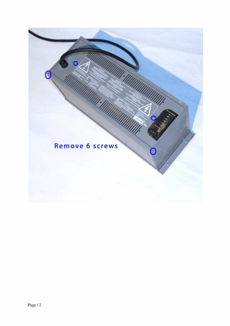
Page | 2
Page | 3
Page | 4
Page | 5
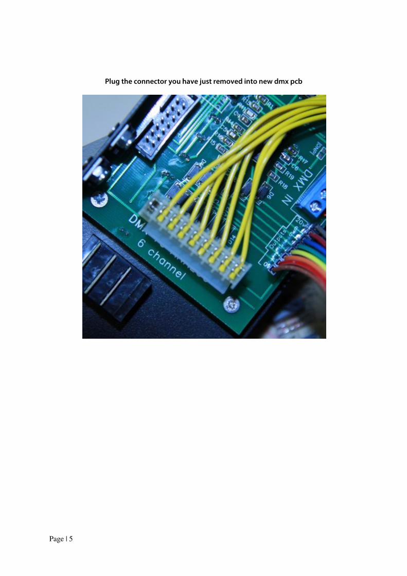
Plug the connector you have just removed into new dmx pcb
Page | 6
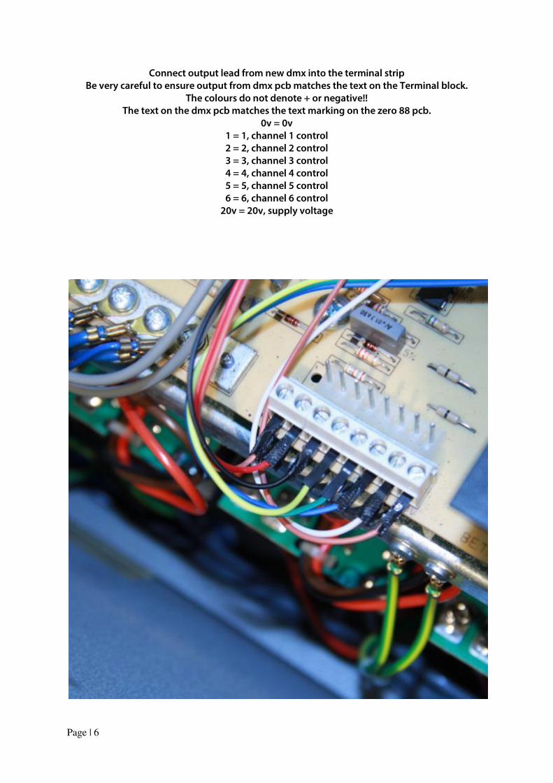
Connect output lead from new dmx into the terminal strip
Be very careful to ensure output from dmx pcb matches the text on the Terminal block.
The colours do not denote + or negative!!
The text on the dmx pcb matches the text marking on the zero 88 pcb.
0v = 0v
1 = 1, channel 1 control
2 = 2, channel 2 control
3 = 3, channel 3 control
4 = 4, channel 4 control
5 = 5, channel 5 control
6 = 6, channel 6 control
20v = 20v, supply voltage
Page | 7
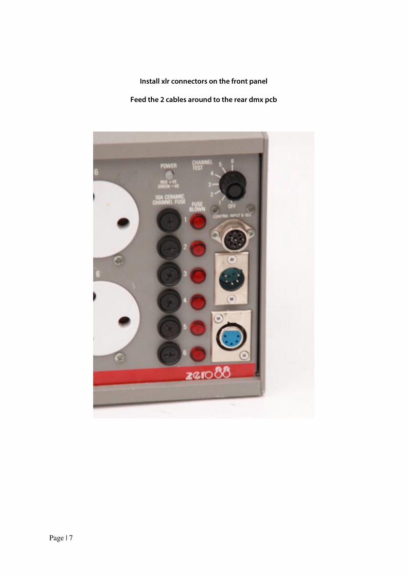
Install xlr connectors on the front panel
Feed the 2 cables around to the rear dmx pcb
Page | 8
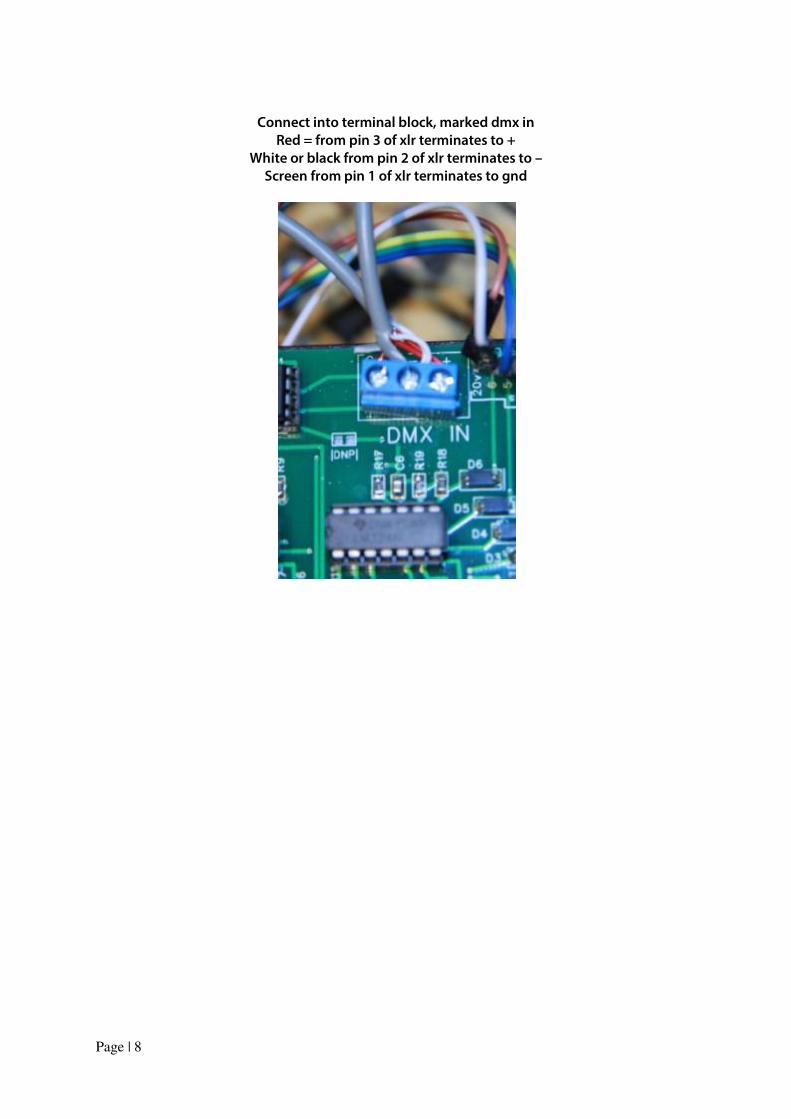
Connect into terminal block, marked dmx in
Red = from pin 3 of xlr terminates to +
White or black from pin 2 of xlr terminates to –
Screen from pin 1 of xlr terminates to gnd
Page | 9
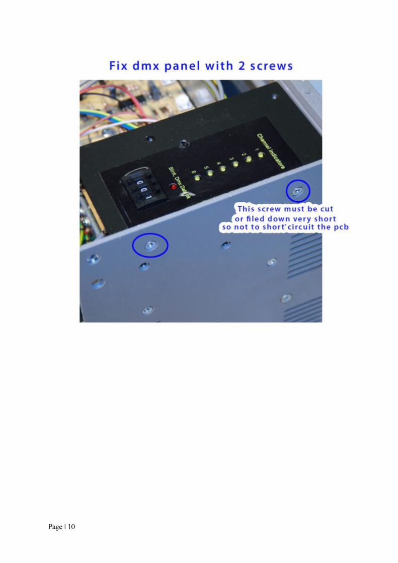
Page | 10
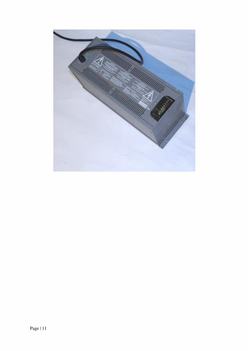
Page | 11
Page | 12
Dmx data led = permanent ‘on’ shows internal 5v line operating, and dmx pcb powered correctly Dmx data led flashes to confirm dmx signal from lighting desk present Dmx Address 600 Slow crossfade chase around all 6 channels Dmx Address 601 = Channel 1 full on Dmx Address 602 = Channel 2 full on Dmx Address 603 = Channel 3 full on Dmx Address 604 = Channel 4 full on Dmx Address 605 = Channel 5 full on Dmx Address 606 = Channel 6 full on Remove lamps from dimmer Channel 2 output led flashes the number of times to correspond to the dmx thumb wheel 1 dmx address Dmx Address 701 = single flash Dmx Address 702 = double flash Dmx Address 704 = 4 flashes Dmx Address 708 = 8 flashes Remove lamps from dimmer Channel 1 output led flashes the number of times to correspond to the dmx thumb wheel 2 dmx address Dmx Address 710 = single flash Dmx Address 720 = double flash Dmx Address 740 = 4 flashes Dmx Address 780 = 8 flashes