Embed Size (px)
Citation preview

71V-AO94 399 AIR FORCE INST OF TECH WRIGHT-PATTERSON AFB OH SCHOO-ETC F/6 20/5A DISC-LOADED MICROWAVE GUIDE FOR LASER APPLICATIONS.(U)DEC 80 M 8 TUTIN
NCLASSIFIED AFITIGEPPPHPI0-11 NL
I uinummmmuummmI-I-EEmmmmI-

tARN

AFIT/GEP/PH/80-1 1
14 ,JAN 198'
FOR PUBLIC RELEASE AFR 19017
APPRC\FOR
C'~
Kit 0(e W' SoAl *
A DISC-LOADED MICROWAVE GUIDE
FOR LASER APPLICATIONS
THESIS
AFIT/GEP/PH/80-11 Michael B. TutinCaptain USAF
A )
Approved for Public Release; Distribution Unlimited
AFIT/GEP/PH/80-11
A DISC-LOADED MICROWAVE GUIDE
FOR LASER APPLICATIONS
THESIS
Presented to the Faculty of the School of Engineering
of the Air Force Institute of Technology
Air University
in Partial Fulfillment of the
Requirements for the Degree of
Master of Science
by
Michael B. Tutin, B. A.
Captain USAF
Graduate Engineering Physics
December 1980
Approved for Public Release; Distribution Unlimited

PREFACE
This investigation represents a very small part of a
concerted effort at the Air Force Avionics Laboratory to
develop effective laser systems for Air Force applications.
Microwave power is readily obtainable for airborne use and
is easily handled. A microwave-pumped laser would also not
have the electrode degradation and contamination problems
associated with other systems. Therefore, lasers excited by
microwaves show definite potential, but, to date, research
in this area has been limited. This study was suggested by
Dr. W. Schuebel of the Avionics Lab to determine the
suitability of a disc-loaded microwave cavity for laser
applications. While the disc-loaded microwave cavity has
been used elsewhere, its usage in a laser system is unique.
Special thanks are due to Dr. Schuebel for his idea and
sponsorship of the project. Dr. E. Dorko of the Air Force
Institute of Technology and J. Brandelik of the Avionics lab
also suppled invaluable aid. I would also like to
acknowledge the timely and precise work of Mr. J. Brohas,
who fabricated the cavity, the skill of Mr. S. Derby who
supplied a lot of the technical expertise for the project,
and the expert glassblowing of Mr. R. Wade.
ii

Cont!Qts
PagePreface................................................. ii
List of Figures......................................... iv
Abstract................................................ v
I. Introduction.............................. 1
Background........................................ 2Objective......................................... 3
I. Theory .. ................................ 5
Choice of the Cavity.............................. 5Cavity Characteristics........................... 11Microwave - Pumped Lasers........................ 15
III. Experimental Apparatus........................... 18
Microwave Conponents............................ 18
Laser Application Components..................214
IV. Experimental Procedure ........................ 27
Introduction..................................... 27Characterization of the Cavity.................... 27Optimization of the Plasma Discharge..............29Spectroscopic Measurements........................ 30
V. Results and Discussion........................... 32
Introduction..................................... 32Properties of the Microwave Cavity................32Parameters for the Plasma Discharge.............. 38Laser Properties of the System................... 41
VI. Conclusions...................................... 414
VII. Recommendations..................................147
Bibliography...................................49
Vita ... .... ... ... .... ... .... ... ... .... ... .5
Li

List -of Figures
Figure Page
1 Periodic Cavity-Chain Structure ................... 8
2 Side View of A Disc-Loaded MicrowaveCavity ........................................ 10
3 The TM0 1 Waveguide Mode ........................... 12
4 Brass Disc-Loaded Cavity .......................... 19
5 Experimental Arrangement of
Microwave Components ......................... 21
6 Schematic For Microwave Components .............. 22
7 Experimental Arrangement of Opticsand Vacuum System ........................... 25
8 VSWR Vs. Frequency For Optimum Geometry ......... 33
9 VSWR Vs. Frequency For Non-OptimumGeometry ..................................... 34
10 Reflected Power Spectrum For OptimumGeometry ........................................... 36
11 Reflected Power Spectrum ForNon-Optimum Geometry .......................... 37
12 Spectrogram for Argon Discharge. LabelledSpectral Lines are Known Argon Ion LaserTransitions ...................................... 42
iv

ABSTRACT
A brass disc-loaded microwave cavity was built and the
feasilibity of using it as the pump for an argon ion laser
was investigated. The cavity was 3 feet long and its
insertion loss was measured to be 6.3 db. The voltage
standing wave ratio for an empty cavity was found to be
below 1.5 at all frequencies from 2425 MHz to 2475 MHz. A
quartz laser tube was inserted in the microwave cavity and
filled with .50 torr of argon. A uniform discharge was
obtained with 180 W of input power, and a spectral analysis
revealed that previously known laser transitions occurred in
the discharge. A laser cavity was formed, and a "fireball"
was observed in the discharge. However, attempts to optimize
the system to obtain lasing were not completed. It was
concluded that improvements must be made to the cavity to
decrease the insertion loss and to the power supply to more
effectively couple power to the plasma.
V

A DISC-LOADED MICROWAVE GUIDE
FOR LASER APPLICATIONS
I. INTRODUCTION
The pumping of lasers with microwaves is a promising
development in laser research. The process has many
advantages over other excitation methods, such as the dc
discharge, and has been investigated by several authors
(Refs 1; 2; 3; 4; and 5). They all point out that the
electrodeless configuration of the microwave discharge
eliminates contamination problems. In addition, it is felt
that the higher electron temperatures found in microwave
discharges lead to greater efficiencies for lasers. These
hypotheses have been tested (Refs 1; 3; and 5); but, while a
solution to the contamination problem has been demonstrated,
increases in efficiency have not been substantial enough to
warrant an abandonment of traditional excitation methods.
The design of the waveguide for the microwaves may be
the key to increasing laser efficiency. Most of the previous
researchers in this area have utilized rectangular
waveguides to excite the laser medium. A disc-loaded radial
waveguide yields higher electron energy distributions (Ref
6:196) than a rectangular waveguide, and, therefore, should
lead to higher fficiencies. A circular waveguide also has a
greater power - handling capacity (Ref 7:97) which would be
important for high energy laser applications. In short, the
'mono"

construction and testing of a disc-loaded microwave guide
for laser applications is definitely warranted by the above
and is the basis for this investigation.
BACKGROUND
The development of radar and microwave technology in
the 1940's led to the consideration of microwaves as a
source for exciting plasmas. Brown and others advanced the
theory of microwave discharges for applications in the
fields of plasma chemistry and spectroscopy (Refs 8 and 9).
Maksimov suggested the use of microwaves as the pump for a
gas laser in 1966 (Ref 10:422). However, most of the re-
search to date on gaseous lasers has been conducted with dc
discharges.
A comparison of dc discharge lasers and microwave
discharge lasers is instructive. Muller et. al. have
summarized the disadvantages of a dc discharge laser (Ref 4:
1012-14). First of all, lasers pumped by dc discharges have
low efficiencies. George (Ref 2:1152) attributes this to the
steady - state electron energy distribution in the dc
discharge. This distribution is characterized by large
electron densities at low energies which do not
significantly contribute to upper laser level excitation. A
second disadvantage is the high voltage required for a dc
discharge, which makes it difficult to construct portable
systems and increases warm-up time. Finally, under the
2

influence of high voltage, the electrodes decay. This
phenomenon reduces the life of the laser, and also
introduces contaminants into the plasma. This contamination
can quickly stop the lasing process, especially in metal
halide lasers. In short, while dc discharge lasers have
found wide-spread use, there are severe shortcomings in
these systems.
Gaseous lasers that are pumped by microwaves do not
have these problems. Again, Muller t.al. and others have
theoretically argued the advantages of a microwave-excited
laser. The microwave discharge is stable and has a higher
energy density than a dc discharge. This stability makes it
possible to utilize the pump energy more efficiently (Ref 4:
1014).
The use of microwaves can theoretically improve the
parameters of gaseous lasers. Increasing the electron
temperature of the plasma under steady - state conditions
increases the efficiency of the laser and the microwaves do
this with a non-Maxwellian energy distribution (Ref 4:
1013). Microwave discharges are also electrodeless, thus
eliminating electrode degradation and contamination problems
(Ref 1:7). Compact, portable systems may also be cons-
tructed using transistorized microwave elements.
OBJECTIVE
The above discussion clearly illustrates the
3... ,*++ - . -.i ... +...+.. i +; " ' .. ... .++-,,

desirability of utilizing microwaves as the pump for gaseous
lasers. The purpose of this investigation was to construct a
disc-loaded microwave guide and to test known laser species
in the system. The basic design of Van Koughnett et.al.
(Ref 6:197-209) was used in the design for the microwave
cavity, and the laser gases chosen for study were helium
(for use it a helium-cadium laser) and argon. These species
were picked because much is already known about them and
comparisons can readily be made with existing laser systems
that utilize these same species but different excitation
mechanisms.
4I

II Ti ry
The theoretical aspects of this experiment will be
discussed in this section. First, the design advanced by Van
Koughnett et. al. for the microwave cavity will be vali-
dated. To accomplish this, the basic mechanism of the
microwave discharge will be explained, and some elementary
waveguide theory will be introduced. Secondly, the spect-
roscopy required to understand the laser applications of the
cavity will be outlined. The processes in the helium-cadmium
mixture will be emphasized.
CHOICE OF THE CAVITY
The design of Van Koughnett, Dunn, and Woods was
employed in this study (Ref 6:197-204). In their article
these researchers have given the theoretical foundation for
the cavity design and their development will be paralleled
and expanded here. However, the operation of a general
microwave discharge system will first be covered, and will
be followed by a short description of slow wave
electromagnetic systems.
McTaggart has succinctly described plasma excitation in
electrical discharges (Ref 11:15). A discharge results when
free electrons are accelerated in an electric field until
they attain sufficient energy to cause ionization or
excitation of some of the gas molecules in the plasma.
Depending upon the energy levels of the gases and the
5

'M4
electron energy distribution, various excited states
(including upper laser states) of the atoms and molecules
may be created.
The advantages of a microwave discharge over a dc
discharge have already been enumerated, so the remaining
problem is the choice of the geometry for the microwave
cavity. Previous workers in the field have utilized only
rectangular waveguides for the microwaves. Muller et.al.
have built a helium-neon (He-Ne) microwave-excited laser
(Ref 5:1302-1303). They used a very short gain medium (4cm
long) and a 27V power supply for the microwaves, thus
demonstrating that a compact, portable system could be
built. They achieved a power output of .25mw, which compares
favorably with other systems, and hypothesized that vast
improvements could be made.
Handy and Brandelik have reported on microwave
excitation of a pulsed CO 2 laser (Ref 3:3755). They found a
0.7% increase in efficiency when a microwave discharge was
used instead of a dc discharge. This increase is not trivial
as the efficiency of CO lasers is usually less than 25%2
(Ref 12:81).
The above work demonstrates that microwave excitation
can yield definite improvements in the parameters of gaseous
lasers. However, it is not clear that a rectangular
waveguide geometry is necessarily the best for efficiency.
Asmussen et.al. have stated that these systems are generally
6
restricted to small plasma volumes and low pressures (Ref
13:109). In addition, such structures are characterized by
non-uniform fields and are very difficult to analyse
electronagnetically.
A circular waveguide does not have these undesirable
characteristics. It has a greater power handling capacity
and a lower attenuation than a rectangular waveguide. How-
ever, a hollow circular guide will not effectively couple
the microwave energy to the plasma. To do this, one must
employ some type of slow wave structure. A slow wave
structure makes the wave velocity of the microwaves
approximately equal to the velocity of electrons in order
that the electric field of the wave will travel with the
electrons and accelerate them (Ref 14:VII). In other words,
a slow wave structure slows down the microwaves so that
their energy may be coupled to the electrons.
Bevensee details one slow wave structure, the periodic
cavity-chain shown in Figure 1. (Ref 14:5-14).
He states that the electric field in the z direction,
Ey may be written as
E z(r, O,z) = Vm (Z) mz(r,O) (1)
Vm(z+L) = V m(z)e-jBOL
7
\ 7
Figure 1. Periodic Cavity-Chain Structure
where Bo is the propogation constant of the wave, emz is a
waveguide mode pattern of a circular waveguide, and Vm(z) is
a complex amplitude. This amplitude can be expanded in a
Fourier series as
Vm(Z) Vmne-jBnz +jwt , B0 : B + 2n (2)
where w is the frequency of the wave.
These equations can be used to solve Maxwell's
equations in the cavity chain, and, therefore, determine the
energy coupling of the structure. However, that development
requires a detailed mathematical formalism, and will not be
pursued here. Bevensee does give the Marcuwitz-Schwinger
8

technique and the resonant cavity mode technique for
obtaining solutions(Ref 14:27-36). In this instance, a
common sense analysis does yield a useful feel for the
processes in the structure. The discs in Figure 1. would
slow a stream of water coursing in the pipe. In the same
way, microwaves are slowed, and electrons may then absorb
power from them (Ref 14:2). These power gains from the
electric field can be tremendous even over short interaction
lengths.
Asmussen et . al . have developed a cylindrical
waveguiding system which is able to sustain a plasma (Ref 13:
109-117). It consists of a plasma cavity terminated at one
end by a fixed short and at the other by a variable short.
The microwave power is coupl2d to the resonances of the
plasma cavity by physical tuning of the variable short.
This system was used to investigate chemical reactions in
microwave discharges but Asmussen et. al. also stipulated
that it could be used as an active plasma for a laser.
A different cylindrical geometry has been proposed by
Van Koughnett, Dunn, and Woods (Ref 6:195-209). They
designed a disc-loaded circular waveguide structure as an
applicator for microwave heating of filamentary materials.
This system consisted of periodic cylindrical sections with
irises that form a disc-loaded structure and two identical
transition and transformer elements, as illustrated in
Figure 2. The authors state that this structure yields a
9

0 ) C 0
00
C3cs 73 r. C~ E CI. 0 -
e 0 c H"
- r C w - 0 -+j 0 --
0
4-2
I
4-4- 0 0U) -4 1
= 4 4-3
C i r , .C.. . . . -)
i 4 ) ,-
- ~ L. ---------.
0 lz
0 0
4- CS2 Vco
j..a)
T-4
H
............... -..* ~*--*-*---.*.--*.-.-*-*.-...-.- .** - .... - -
Cd

-- - .. . . . r . ..
uniform field distribution throughout the cross section of a
cylinder approximately one inch in diameter for a 2450 MHz
applicator and also is very efficient. These factors and the
relative simplicity of the disc-loaded section make this
cavity an attractive candidate for use in a laser system.
Ti,, filarent in Figure 2 would be replaced by a laser tube,
which would also have appropriate Brewster windows and
mirrors aligned to it. The system would be mechanically
complex, but would have the advantages already mentioned for
cylindrical systems.
£ AYJLJ_._ X _ LAR. C _TF LRILC _S
The geometry of the microwave cavity depicted in Figure
2 on page 10 must be completely specified to achieve the
desired results. The first requirement of the system is that
a uniform field exist throughout the cross section of a
cylinder. The TM 0 1 mode of a circular waveguide meets This
requirement and is shown in Figure 3.
Since each mode of a circular waveguide has a cut-off
wavelength which is a function only of the inside diameter,
the diameter 2b is chosen such that only TM 0 1 and TE 1 1 modes
are possible (Ref 15:61). The TE 1 1 mode is then suppressed
by a method which will be discussed later.
The next step is to determine the dimensions of the
disc-loaded section. Given an operating frequency of 2450
MHz, one would necessarily want this frequency to correspond
11

/
Figure 3. The TM 0 1 Waveguide Mode
to the center of the passband of the structure. To
accomplish this, the dispersion relation (Ref 14:102) for a
disc-loaded cavity is used,
f = (f2 +f1 )/2 - 1/2(f 2 -f 1 )cos Bw (3)
where f2 and f1 are the upper and lower cut-off frequencies of
the passband, Bw is the phase shift per period of the
structure, and w is the period of the structure as shown in
Figure 2 on page 10 (Ref 6:196). For f=2450 MHz to be the
center of the passband, Bw must equal 7/2 at this frequency.
Also, for the longitudinal component of electric field to be
uniform over the diameter of the cavity, the phase velocity
of the disc-loaded structure must equal the free space
12

velocity c. Therefore, at 2450 MHz,
Bw = 27iw/X 0= T/2 (4)
where X is the free space wavelength c/2450MHz. This
leads to W=X /4 = 1.204 inches.
The fact that the phase velocity equals c also helps to
determine the diameter 2a of the hole in the discs.
Walkinshaw (Ref 16:248) gives the peak longitudinal
component of electric field E in the disc hole diameter as
E = X 0V480P/7Ta2
where P is the RMS value of the power flow along the
structure. Van Koughnett et. _aLj arbitrarily limit E to 3000
volts/cm to avoid breakdown problems, and with a power level
of P=5KW, equation (5) indicates that 2a cannot be less than
1.1 inches to achieve maximum coupling.
Walkinshaw also developed the theory for determining
the diameter 2b (Ref 16:248). Using his results, Van
Koughnett et. al. theoretically obtain 2b= 3.810 inches
for f=2450 Mhz. However, they also determined this value
experimentally by finding resonances of a two period disc
loaded section. The value 2b = 3.791 inches was used by
them. Therefore, all of the dimensions of the disc-loaded
section have been determined, but the transitions to and
13

from it must still be specified.
Standard rectangular waveguide can be used to carry the
micrc'.aves to and from the cavity. Ragan (Ref 17:380) gives
the rethod for deriving a transition from rectangular
wave,tide to TM01 mode circular waveguide. For a 4 1/8 inch
circtlir guide, Van Koughnett et. al. measured the radiation
pattern of the antenna formed by an open-ended circular
waveguide and adjusted d to yield a null in the direction of
the circular waveguide axis. This suppresses the TE1 1 mode
and only TM 0 1 mode propagation is possible. The value of d
obtained in their experiment was .060in.
Finally, the last requirement is a transformer section
to match the TM01 mode waveguide to the disc-loaded section.
The characteristic impedances of the two sections differ
drastically, so the transformer section will be somewhat
complex, as shown in Figure 2. Van Koughnett ei. al.
basically designed the transformer as a two section quarter-
wave transformer. The second transformer section with
dimensions 2a' and 2b' will give a phase shift of 900 if
those dimensions yield a characteristic impedance of z0
where Z o0 is the characteristic impedance of the disc-loaded
section. They measured Z and then stipulated that the14
characteristic impedance varies as a , where a is the radius
of a disc. Therefore for two different discs
(a'/a) 4 ZY/ (6)
14

Since they experimentally measured Z to be 2.66, Eqn (6)
yields 2a' = 1.4 inches. The required value of 2b' was
determined to be 3.880 inches by the same method employed to
find 2b.
The remaining transformer section must complete the
impedance match, and, therefore, have a characteristic
impedance of Z/2 However, previous errors and imperfections
of the system make a theoretical determination of the first
transformer section parameters impractical. Instead, Van
Koughnett et. al. determined h and 2a" experimentally to
insure the best impedance match.
The above discussion completely defines the geometry of
the microwave cavity except for h and 2a". In their
application of heating filaments, Van Koughnett, Dunn, and
Woods state that the cavity promises stronger coupling, a
more uniform heating cross-section, and higher efficiency
than other waveguide geometries. These same advantages hold
great promise for use of the cavity in a laser system.
BICROWAVE-PUMPED LASERS
Some advantages of microwave discharge lasers have been
enumerated above, and various work in this field has been
cited. Still, it is not clear that microwave pumping of
lasers provides overwhelming advantages over other systems.
The few microwave laser systems mentioned in the previous
discussion demonstrated the feasibility of this excitation
15
L.L

method, but the obtained results do not warrant an
abandonment of traditional excitation methods.
It is also not clear what types of laser systems are
best-suited for microwave excitation. Chemical, ion, and
metal vapor lasers are all possibilities, but it has not yet
been established which particular system would best use
microwave excitation. This investigation, with the use of
the unique waveguide structure, yields at least a partial
solution to this problem.
An essential factor for the utility of the microwave
discharge is its electron energy distribution function. An
experimental determination of this function would be ideal,
but, unfortunately, is beyond the scope of this work.
However, an indirect indication of the form of the electron
energy distribution function can be obtained by comparing
the available experimental results with previous data from
hollow cathode discharge (HCD) work. The electron energy
distribution function for a HCD in helium has been measured
(Ref 18:84), and was found to be strongly non-Maxwellian
with a high concentration of high-energy electrons. Schuebel
found six new CW laser lines ir a helium-cadmium HCD and
attributed them to this non-Maxwellian electron energy
distribution function (Ref 19:574). These iines (5337 A,
0 0 0 0 05378 A, 6335 A, 6360 A, 7237 A, 7284 A) have not been found
in positive column discharge lasers, which are characterized
by Maxwellian distributions. Therefore, if it can be shown
16

that these transitions occur in a microwave helium-cadmium
system, it may logically be inferred that the microwave
discharge distribution function is non-Maxwellian with a
high concentration of high energy electrons.
The measurement of the spontaneous emission spectra of
any discharge provides a relatively simple method for
roughly determining excited state populations. For instance,
the spontaneous emission spectra of helium and argon can be
measured for a microwave discharge as a function of the
input microwave power, the gas pressure, and the plasma tube
bore. In this way, the optimum configuration for argon and
helium-cadmium lasers that are pumped by microwaves may be
determined. Once these configurations are found, the
important parameters of these lasers, like efficiency and
wavelength, may also be measured. This data base can then be
used to draw conclusions about the suitability of further
microwave excitation studies.
17

I
III EXPERIMENTAL APPARATUS
The experimental apparatus will be described in this
section in two parts. First, the microwave cavity and
associated microwave components will be described. Secondly,
the laser application components, including the vacuum
system and discharge tube, will be listed.
IIICROWAVE COMPONENTS
The microwave cavity design of Van Koughnett et.
was used in this work. The cavity design is illustrated in
Figure 2 on page 10, and the specifications are given there
and in Chapter II. The waveguide dimensions are d=.060", 1
=2", w=1 .2014", 2a=1 .1" 2b=3 .791", 2a=1 .4"1, 2b=3.880",
h=.7", and 2a"=2.6". The cavity is pictured in Figure 4. The
discs were machined to have shoulders so that each disc
would interlock with the circular waveguide section on
either side of it. This allowed easy assembly of the
apparatus and the flexibility to change the over-all length
of the cavity by removing sections of the disc-loaded
portion. Three rods external to the cavity were bolted at
the end plates to insure firm contact of all brass pieces.
The rectangular waveguides at the input and output ends were
soldered to the 4 1/8 inch circular waveguide sections. The
excess solder was then milled out so that the dimension d
was again .060 inches. Care was taken in the machining and
18

Figure 4. Brass Disc-Loaded Cavity
handling of the brass to prevent scratches, gouges, and
other imperfections. However, the brass surfaces could not
be totally protected. The cavity was dipped in a degreasing
solution to provide a clean inner surface. The transformer
discs were also constructed with shoulders so that from the
input 4 1/8 inch circular section to the output one, all the
brass pieces fitted together snugly. Eighteen disc-loaded
sections were fabricated, giving the structure an active
length of three feet.
The cylindrical stubs on either end of the cavity were
designed to prevent leakage from the cavity while allowing
the insertion of a plasma tube. The diameter of .75" for the
19

stub cuts off microwave radiation at 2LI50MHz, since it is
below the lowest circular waveguide diameter fcr propagation
at that frequency. However, it was found during the
experiment that a plasma in the cavity conducted power out
the end (2mw of leakage was measured with a Microtek 310
leaka ige meter). Therefore, an aluminum foil cone was placed
around the cavity ends to prevent any stray radiation. Three
1/4 inch diameter viewing ports to observe the plasma were
drilled in the circular waveguide sections at the ends and
in the middle of the cavity. There s no detectable leakage
from these ports or anywhere else in the structure.
The microwave cavity was supported on an optical bench
by 3 y mounts that were fabricated specifically to match the
curvature of the cavity. The remaining microwave components
needed to operate and characterize the structure were then
connected at either end of the cavity. The experimental
arrangement is shown in Figure 5 and Figure 6 gives a
schematic for the set-up.
Three different sources were used to supply microwave
power to the system. A Hewlett Packard (HP) 8620 C sweep
oscillator was used in the characterization studies of thc
cavity; a Raytheon model PGM-1O was used to supply CW power
to the system; and a Peschel Instrument Inc. 500W magnetron
was used to supply higher CW power. The isolator was an
Airtron model IL-241F PS-14 and the waveguide to coaxial
adapters were all HP's. The 10 decibel (db) directional
20

*
Figure 5. Experimental Arrangement of MicrowaveComponents
coupler was a HP model 87620 and the 3db coupler an HP
S752A. The attenuators indicated are combinations of Narda
20 db couplers with various Weinschel Engineering coaxial
attenuators. The small loads were Microwave lab 10 watt
loads. The large load was a HP model S912-A. The input and
transmitted power meters were HP 432B meters with Struther's
model G/L-360 detector mounts. A Boonton Electronics model
42-A power meter with 41-4B detector mount was used to
measure the reflected power. The circulator was a Merrimac
FCW-584 and the E/H tuner was a FXR S312A. The slotted line
was a HP S-810A and a PRD 250A probe was used in it. This
probe, with a IN21C diode, was connected to a PRD 277-D
21

I Cd
I 0r-q 0
0
.
S4-)
C-)
0 0 4J
4.))
~-4H+-
- . - -- -
22.
0.~niniL

SWR/attenuation meter. Finally, an Electro Instruments X-Y
recorder model 400, was used to observe the reflected power.
When the Peschel magnetron was used, it became
neces-;ary to modify the arrangement of Figure 6 because of
the [.:trher power levels. The 10db coupler was replaced by a
PP S7OD 20db directional coupler and a Raytheon CSH148
circulator was used instead of the Merrimac due to its
higher power rating. The coaxial attenuators could not be
used either, and a rectangular waveguide section with a
small loop in it was used to sample the reflected power.
The loop coupling factor was experimentally determined, and
was found to vary with input power. Therefore, the reflected
power found using it could not be guaranteed and was only
used to determine trends in the reflected power. The
waveguide with the loop was terminated by a Raytheon LSH 102
load. On the transmitted side of the cavity, the 3db coupler
was replaced by the 10 db coupler that had been on the other
side. This still required particular attention in operation
because the transmitted power circuit could not handle the
full power of the magnetron. Therefore, the discharge was
always well-established and absorbing a large portion of the
power before the higher power levels were selected.
A final configuration of the system involved using both
the Raytheon and Peschel generators to supply CW power. The
Peschel generator input side remained unchanged from the
previous set-up. On the other side of the cavity, the 10db
23

coupler was disconnected and its direction was reversed. The
input side of the coupler was then connected to the Raytheon
generator. On the output side of the coupler, a Raytheon
circulator was used to direct the reflected power (and the
transmitted power from the other side) into a HP 10OW load.
Another calibrated loop in a short waveguide section before
the load was used in measuring this power. A FXR E/H tuner
between the circulator and the microwave cavity completed
the circuit.
One additional microwave circuit was used at times. A
FXR N410A frequency meter replaced the load in the reflected
power circuit in Figure 6 and was connected to a HP 120 B
oscilloscope. The microwave source also supplied a signal to
the oscilloscope and this provided a means to measure the
frequency of the source.
LASR APPLICATION COi _ gIEZjT_
The laser application components consist of a vacuum
manifold and associated equipment, the discharge tube, and
the required optics for completing the system and making
measurments. An over-all view is given in Figure 7. A Welch
Scientific turbopump was used. The manifold was configured
so that six different gases could be used in the system. A
Granville Phillips ionization gauge with a Fluke 8300 A
digital volt meter was used to measure the low pressures
9down to 10 torr.
24

... .- . . .... -'- - " - '
.. .. .. ..... ... . .... . ... ."
Figure 7. Experimental Arrangement of Opticsand Vacuum System
The discharge tubes were made of quartz to handle the
microwave heating. Quartz windows were epoxyed to either end
and the tube was connected to the rest of the system using a
T-section. Leak checks of the system were performed with a
Tesla coil.
Two laser tubes were also constructed with inside
diameters of 1.83mm and 3.5mm. The 1.83mm tube was
capillary. Bell flares were made at each end of the laser
tubes and these flares were ground to a Brewcter's angle of10
555 . Once the tubes were inserted in the microwave cavity,
Lambda/Airtron 13mm elliptical Brewster windows were epoxyed
on. Broad band mirrors with reflectivities of 99.9% were
25

I
then put on Lansing Research Corp mounts to complete the
laser system.
t model 82020 Jarrell Ash spectrometer with collimating
optics was used to measure the emission spectra of the
microwave discharges. An EMI 9558QB photomultiplier was
powered by a Power Designs high voltage source at 1680V, and
was placed at the exit slit of the spectrometer. The
photomultiplier signal was sent through a 10K load resistor
and then to a Varian G-2000 recorder.
26

IV EXPERIMENTAL PROCEDURE
INTRODUCTION
This section describes the procedures used in this
investigation. First, the method utilized to characterize
thc microwave cavity will be detailed. Then the procedures
used to determine the best conditions for an excited plasma
in the cavity will be outlined. The parameters that were
varied included the input microwave power, the pressure of
the laser gases in the plasma tube, and the bore of the
plasma tube. Finally, the methods used to investigate the
laser properties of the system will be specified.
CHARACTERIZATION OF THE CAVITY
The microwave cavity described in the previous section
first had to be characterized. The dimensions h and 2a"
needed to produce the best impedance match in the
transformer had to be determined expermentally. The passband
for the structure also had to be determined, and the voltage
standing wave ratio (VSWR) had to be measured. All of these
tasks were accomplished with the set-up illustrated in
Figure 6 on page 22. Actually, various geometries with
different dimensions h and 2a" were tested.
One of these configurations was assembled and the
cavity was connected to the rest of the system. The HP sweep
oscillator supplied the input signal, and its frequency
27

tuning was calibrated with the FXR frequency meter and the
oscilloscope. However, this equipment had an error of 1 MHz
and the frequency also varied with temperature, which could
not be controlled in the laboratory. It was found that the
VSWR of the structure varies rapidly with frequency, and,
therefore, the inability to precisely control the frequency
input meant that VSWR measuremuents could not be reproduced
exactly. Stopbands and passbands could still be determined.
The VSWR was measured for each configuration at various
frequencies in the range from 2420 MHz to 2480 MHz. The
slotted line, probe, and SWR meter were used for this, and
consistent results were obtained with the above noted
exception. A plot of VSWR versus frequency was then made for
the structure to determine its impedance match.
The variation of reflected power with frequency also
gives a good indication of a structure's impedance match.
Therefore, the reflected power measured at the Boonton meter
was inputted to the XY recorder, and the other input came
from the sweep oscillator. The sweep oscillator was operated
in the sweep mode, with a frequency sweep range of 200 MHz
centered at 2450 MHz. The power spectrum obtained on the XY
recorder could not be easily calibrated, but still gave a
solid indication of the cavity's impedance match.
All of the above measurements were conducted with an
empty cavity and with the E/H tuner set to have no effect.
It was desired to see what effect a plasma in the cavity
28

might have on the system. To simulate a plasma, an aluminum
rod was placed in a quartz tube and this system was inserted
down the center of the cavity. This was the worst possible
case for a plasma, and the VSWR and power spectrum
measurements were then repeated.
The E/H tuner was utilized to determine the minimum
VSWR which could be obtained. This was performed at various
frequencies for an empty cavity and for one loaded with an
aluminum rod and quartz tube. The final choice for the
cavity geometry was then made, and attention was then
focused on determining the optimum conditions for an excited
plasma in the structure.
_P IIMTZATION OF LUE _ASE A DISCHARGE
With an appropriate cavity, the other parameters of the
system, including the input microwave power, the gas
pressure, and the bore of the plasma tube, could be
optimized for laser applications. Three tubes of inside
diameter 8mm, 3.5mm, and 1.8 mm were used and plasmas
generated in helium and argon gas were studied. The gas
pressure was varied continuously down to hundreths of a
torr with the vacuum system and the Raytheon microwave
generator supplied up to 90 watts of input power. The
spectrometer was used to obtain the spontaneous emission
spectra in the plasma tube.
A completed tube was inserted down the length of the
29

microwave cavity and supported at either end on the optical
bench exterior to the cavity. The final connection was made
to the vacuum system in place, and the tube was pumped down
and degassed. A vacuum of at least 9 X 10 - 9 torr was
obtaired in each case. Microwave power was then supplied to
the -y.stem, and the input, reflected, and transmitted powers
were measured. In this way, the losses of the cavity could
be determined.
The gas (argon or helium) was then fed into the plasma
tube. At various pressures and input power levels, the
resultant discharge in the tube was observed and studied.
The input, reflected, and transmitted powers were
continuously monitored, and E/H tuning was used to minimize
the reflected power. Initially, the Raytheon generator was
used as the power source, and when higher power levels
seemed to be warranted, the Peschel unit was employed. A
final configuration utilized both generators and power was
supplied to both ends of the cavity.
SPECTROSCOPIC MEASH..FENTS
With a discharge in the tube, an attempt was made to
obtain lasing. However, it was first desired to perform a
spectral analysis of the microwave discharge. This was
accomplished for argon using the spectrometer and associated
components described in Chapter III. The system was
30

calibrated with a mercury lamp. A spectrogram for argon was
obtained and analysed for known laser transitions. This
analyL.is was performed to estimate the probability that the
syst,: would lase.
The laser tube was then aligned using a white light
source and a beam splitter. The alignment was checked with a
small He-Ne laser. The 1.8 mm tube could not be adequately
aligned due to sag caused by its own weight and
imperfections in the bore. Sag was also a problem with the
3.5 rrm tube, and a non-conducting hook was therefore placed
through the middle viewing port to support the laser tube.
The system was then aligned, and lasing was attempted with
argon. Power was supplied to each end of the microwave
cavity, and various pressures of the gases were used.
31

V RESULTS AND DISCUSSIOC
The expe imental results will be given and discussed in
this section. The major problems encountered in this study
will also be analysed. First, the results of the microwave
cavity characterization experiments will be given. Then the
plasma optimization studies will be summarized and analysed.
Finally, the laser properties of the system that were
observed will be discussed.
PROPER_TIES OF THE MICOLAVE CAVITY
The VSWR and reflected power spectrum measurements
performed on various geometries of the microwave cavity
revealed that the transformer dimensions h=.7" and 2a"=2.6"
produced the best impedance match. The VSWR measurements for
this final configuration are shown in Figure 8. This graph
compares favorably with the input VSWR that Van Koughnett
et.al. measured for their structure (Ref 6:202). A plot for
a non-optimum structure (hz. 8", 2a"=2.4") is shown in Figure
9 for comparison. The passbands for the two structures are
similar, but the first structure has a consistently lower
VSWR in the tested frequency range. The structure of Figure
8 was therefore determined to be the most suitable for the
present application. This optimization was further aided by
noting the effect of E/H tuning on the VSWR values. At any
32

cl C"
S 0 0
c? .- C~E
r~4-)
Cl
C)
NIS V; R

Cd
0u
0)
C.
0)
cl~
L6-.,

frequency in the passband, E/H tuning could be used to drive
the VSWR below 1.5.
The final reflected power spectra which were obtained
for thc structure are shown in Figure 10. The solid line in
the acraph is for an empty cavity; the dashed line is for a
cavity loaded with an aluminum rod in a quartz tube. The
passband for the structure is readily seen and confirms the
VSWR measurements. The spectra for a non-optimum geometry
are shown in Figure 11. Although the power units are
arbitrary, the same scaling was used for both plots.
Clearly, the reflected power does not drop as much in the
passband for the non-optimum case as it does for the optimum
configuration. The power spectrum for the loaded cavity in
the optimum case causes a considerable problem. Since the
rod simulates a plasma, the plot indicates that at certain
frequencies, a highly conductive plasma creates a
considerable impedance mismatch. The VSWR of the loaded
cavity was also measured at certain frequencies, and was
always higher than the VSWR for the unloaded cavity at the
same frequency. It was not possible to reduce the VSWR below
4.0 with E/H tuning at several frequencies in the passhand.
However, since the cavity loaded with a metal rod represents
the most conductive plasma possible, it war. felt that the
high VSWR values would not be the over-riding factor in the
usage of the cavity with an actual plasma, which would have
a lower conductivity.
35

Ul)
L))
0
fitC
ED
Nc
itEFUTE POVFIZ(ARITRAY UITS
- ~- . . . . .3 6

Lo)
.41
u
Q
Cl)
C14
REFLECTED~~0>* POI-,(RIRR UIS
37-

The insertion loss was the final important property of
the microwave cavity that was determined. It was measured at
10 different power inputs and the mean value obtained was
6.3db. This was very much higher than the value of 1.7db
that Van Koughnett et. al. obtained for their cavity, and is
definitely undesirable. However, this high value was not
totally unexpected since the brass surfaces of the microwave
cavity were not optimum. Machining and handling of the brass
pieces caused a considerable number of small imperfections
in the waveguide interior. Electro-polishing or silver
plating would have undoubtedly improved the insertion loss,
but were not available options in this experiment. During
system operation, the high insertion loss of the cavity was
evidenced by a marked increase in the temperature of the
waveguide itself. The high losses of the cavity also
required a larger power input than originally planned to
excite the plasma and necessitated the use of the larger
generator.
PARAMETERS FOR TfE IL1SMA DISCHARGE
The microwave power, bore diameter of the plasma tube
and gas pressure were all critical to system operation. The
amount of microwave power that could be coupled to the
plasma proved to be the determining factor in the
establishment of a uniform microwave discharge. The problems
of high reflected power caused by the impedance mismatch of
38

the plasma and the large insertion loss of the cavity
necessitated power levels much higher than originally
anticipated. It was not possible to establish a uniform
discharge the whole length of the cavity with just 90w of
input power from the Raytheon generator. When the Peschel
unit alone supplied input power of 200-300W, the plasma
discharge established in the input end of the cavity became
much more intense, but still did not extend the whole length
of the cavity.
The E/H tuner was used to maximize the length of the
discharge, but it was concluded that a uniform discharge
could not be obtained when the power was fed to the system
from just one end. Therefore, the set-up was changed so that
power could be supplied to both ends of the cavity. Again,
the impedance match was critical, and E/H tuners were used
on both sides of the cavity. The discharge was generally
unstable (the active plasma would jump from one section of
the tube to another and go out altogether at times), but
simultaneous adjustments of the E/H tuners yielded an active
plasma for the whole length of the cavity. It was also found
that the establishment of the discharge was not solely
dependent on the amount of power. The ratio of the input
powers also affected the system. When th- powers were
approximately matched (within 10-20w), the discharge could
be established. However, when the Peschel generator supplied
significantly more power than the Raytheon, the discharge
39

over the entire length could not be established. Increasing
the power level of the Peschel would instead just increase
the intensity of the discharge in one portion of the
microwave cavity. Therefore, system operation was limited by
the low power output of the Raytheon generator.
The bore diameter of the plasma tube was the second
parameter that was investigated. It was desired to have as
large a volume as possible, so the 8mm inside diameter tube
was tested first. However, the large reflection and power
constraints quickly precluded the use of the 8mm tube, as a
discharge could only be established in approximately 1/3 of
the length of the tube. Preliminary investigations showed
that the VSWR of a loaded cavity decreased monotonically
with the bore diameter of the quartz tube (which always
contained a tight-fitting rod). Therefore, only 3.5mm and
1.8mm tubes were investigated further. Uniform discharges in
argon and helium-neon were obtained in both tubes with
approximately 180W of input power from the generators.
The pressure of the laser gases was the last parameter
that was investigated. Various pressures in the range of .2
torr to 10 torr were tried in intervals of .25 torr.
Discharges were established at several different pressures,
but the final configurations had pressures of .50 torr for
argon and 1.75 torr for helium-neon (87.5% helium,12.5%
neon) in the 3.5mm tube.
40
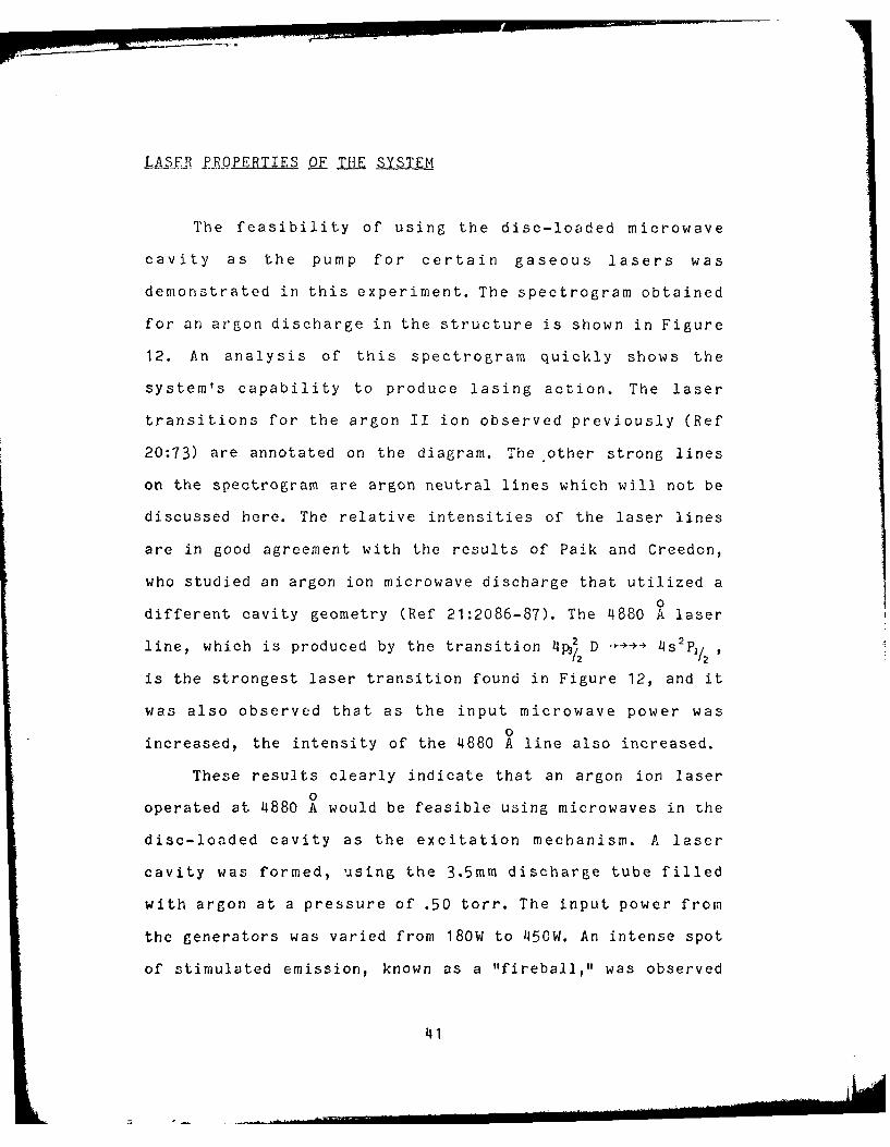
LA.SER -P. PERTIES PE THE SYSTEM
The feasibility of using the disc-loaded microwave
cavity as the pump for certain gaseous lasers was
demonstrated in this experiment. The spectrogram obtained
for an argon discharge in the structure is shown in Figure
12. An analysis of this spectrogram quickly shows the
system's capability to produce lasing action. The laser
transitions for the argon II ion observed previously (Ref
20:73) are annotated on the diagram. The other strong lines
on the spectrogram are argon neutral lines which will not be
discussed here. The relative intensities of the laser lines
are in good agreement with the results of Paik and Creedon,
who studied an argon ion microwave discharge that utilized a
0different cavity geometry (Ref 21:2086-87). The 4880 A laser
line, which is produced by the transition 4 D -- 4 s2p11
is the strongest laser transition found in Figure 12, and it
was also observed that as the input microwave power was
0increased, the intensity of the 4880 A line also increased.
These results clearly indicate that an argon ion laser
0operated at 4880 A would be feasible using microwaves in the
disc-loaded cavity as the excitation mechanism. A laser
cavity was formed, using the 3.5mm discharge tube filled
with argon at a pressure of .50 torr. The input power from
the generators was varied from 180W to 450W. An intense spot
of stimulated emission, known as a "fireball," was observed
41

) U)
0
088' - - -
0 Q0
..... 4 U..
:. $w4 "
~~C,
9.0b$ 4
-- - -1.
$ 9 . . .I.-'
a) 0
So<
42.
.- . -
'<'1g.

in the discharge and indicated that the system was just
below the threshold for lasing. However, attempts to
optimize the system to achieve lasing were not completed.
43L

VI CONCLUSIONS
This study has shown the feasibility of using the
constructed disc-loaded microwave cavity as the pump for
gasec..s lasers. A uniform argon discharge was obtained in
the cavity, and known argon ion laser transition lines were
observed when a spectral analysis was performed. Attcmpts to
optimize the system configuration for lasing were not
completed, but it is felt that. additional work and equipment
changes would readily lead to lasing.
The disc-loaded cavity was first characterized by
measuring its VSWR and insertion loss. The VSWR for an empty
cavity was found to be 1.5 or lower for any frequency from
2425 MHz to 2475 MHz. With a metal rod in a quartz tube
inserted in the cavity to simulate a plasma, the VSWR
increased to values as high as 4.0 in the same frequency
band. This effect also occurred with an actual plasma. The
insertion loss of the cavity was measured to be 6.3 db. It
was discovered that this loss adversely affected the amount
of power that could be coupled to the plasma. A major factor
in the cavity's high insertion loss was the imperfect inner
brass surfaces. A substantial improvement could be obtained
if the inner surfaces of the brass components were electro-
polished or silver-plated. Soldering the components
together instead of press fitting them together would also
reduce the insertion loss. It would be absolutely essential
44

to it::prove on the insertion loss in order to achieve
efficient lasing action.
A uniform microwave discharge with argon and with
helilu:--neon was obtained in the disc-loaded cavity. The
argon 61 ,charge was established at .5 torr in the 3.5mm tube
with , of input power. The He-Ne discharge was produced
under samila7r conditionb except for the gas pressure which
was 1.75 torr. In both cases, the establishment of a
uniform discharge depended heavily on E/H tuning and on
coupling of the power to the plasma. It was determined that
the power inputs to the two ends of the cavity also had to
be approximately matched in order to establish a uniform
discharge. A larger power supply with a splitter could be
used in future work to insure the matching of the power
inputs and greater power coupling to the plasma. Uniform
discharges could also be obtained more easily by reducing
the plasma volume. This could be accomplished by removing
sections of the disc-loaded cavity, or by decreasing the
plasma tube bore diameter. This alternative is not as
attractive as changing the power supply, since it will
usually be desired to maximize the plasma volume.
A spontaneous emission spectrogram for the argon
discharge was obtained and analysed. Known laser transitions
0were identified, and the 11880 A line was the most intense. A
"fireball" was also observed in the discharge when a laser
cavity was formed. These results demonstrate the feasibility
45

of li--rc.i action in the disc-loaded structure. However,
atteisj to optimize the system configuration to obtain
lasin, wcre not completed.
In conclusion, this experiment has only touched on the
preli:iraries of utilizing a disc-loaded microwave cavity
for lcrr applications. The feasibility of laser action was
demonstrated, and further work is warranted. Changes in the
experimental apparatus and the cavity itself would
facilitate this work, and will be detailed in the next
section. Still, the disc-loaded microwave cavity definitely
holds promise for future laser applications.
46

VII RECOMMENDATIONS
The excitation of lasers with microwaves has definite
advantages over other excitation mechanisms, and should be
explored further. The disc-loaded microwave cavity system
used here can be improved upon significantly, and,
therefore, should also be investigated further. The results
of this experiment indicate that changes in the experimental
apparatus and the cavity itself should result n lasing for
an argon ion system. These changes include: (1) driving the
source magnetron only at the particular frequency that
yields the lowest VSWR for a loaded cavity; (2) electro-
polishing or silver-plating the brass components of the
cavity to reduce its insertion loss; and, (3) using a
larger power supply with a splitter in order to couple more
power to the plasma. Once lasing is obtained, the efficiency
of the system should be measured, and a spectral analysis of
the laser beam should be performed. These results should
then be compared and contrasted with similar resul to from
other argon lasers that use different oxcitation mechanisms.
In this way, the desirability of employing microwave
excitation could be determined for an argon ion laser.
The disc-loaded microwave cavity systcri should also be
investigated for use in other types of laser Veyttc::.. Metal
vapor and metal halide lasers are poss;ibilji i.:, . d only
minor modifications would be required to t , (,e n
47

apparatus. A significant advantage of employing microwave
excitation with these systems is that the microwaves could
possibly be used to vaporize the metal, and an external
heating mechanism would riot be required.
.48 ..

1. Brandelik, J. E. and G. A. Smith. "Br, C, Cl, S, and S.Laser Action Using a Pulsed icrowave Disei-! ir~e, '" IEEEJournal of _Q uantuin lectronics, QE-6: 7-8 (Jat 80).
2. George, N. "Improved population Inversion in Goseous[L:crs," ProceedinZs of the _IEEE, 51 : 1152-1153 (AugustC-).
3. Hindy, K. G. and J. E. Brandelik. "Laser Generation bypulsed 2.45 Gliz Microwave Excitation of CO2 ," Journalof Applied Phjscs, 4S_. 3753-3756 (July 78).
4. Muller, Ya. N. et, _od. "Microwave-purped Helium-NeonLaser, Soviet Jour- of Qntum Electronics, L :1013-1015 (August '7).
5. Muller, Ya. N. et_ a_j- "Use of a Transverse I-icrowaveDischarge in a Compact Efficient He-,Ie Laser," Soviet
u _rnal of _Qiiantu m Elect-ronic, q : 1302-1303 (Oct 79).
6. Van Koughnett, A. L. et.al. "A Microwave Applicator forHeating Filamentary aterials," Joural of Microwav.Power a:95-204 (MVarch 74).
7. Lance, Algie L. Introduction to Microwave Tpheor andMj.ejsurements. McGraw-Hill Book Co, New York 1964 308
pages.
8. Brown, S. C. Basic Data in Plasma Physics. MIT Press,Cambridge, Mass: 1959.
9. Herlin, M. A., and Brown, S. C. "Microwave Breakdown ofa Gas in a Cylindrical Cavity of Arbutrary Length,"Physical Review, 7_4:1650-1656 (Dec 1948).
10. Maksimov, A. I. "The Use of a Microwave Discharge As theActive Medium for a Gas Discharge Laser," Optics and__ectrQscoj)y, 21:422-423 (1966).
11. McTaggert, F. K.,Plasma Chemistry in letr i cal_Discharges. Elsevier Publishing Company, New York, 1967.246 pages.
12. Pedrotti, L. and Weichel, H., Lse r Physj_ . Unpublishedcourse notes used at the Air Force Institute ofTechnology, 1980. 237 pages.
13. Asmussen, J. et. a 1., "The Design of a Microwave PlasmaCavity," Proceedings of the IEEE, 62:109-117.
49

14. Bevensee, R. M., L~crmtnticSlow Wave Systems.John Wiley and Sons, Inc, New York, 1964. 464 pages.
15. Wheeler, G. J. Introductqi-on to Microwaves. Prentice-Hall, Inc., Englewood Cliffs, N. J., 1963. 242 pages.
16. Walkinshaw, W., "Theoretical D e s ign of L in ea rAccelerators for Electrons," ProceeinZg of Fby.UcalSociety, _6j-3 5 (1948).
17. Ragan, G. L.., "Microwave Transmission Circuits," MIT1Radiation La oratory f2eriep 0:M~awHl C. eYork, 198:p30
18. Willet, C. S. Introduction to Gas Lasersz oulto
Ijnve~rsion Mechanisims. Pergamion Press, New York, 1974.528 pages.
19. Schuebel, W. K., "Transverse - Discharge Slotted HollowCathode Laser,' IJEEE Jouprnjal of Qu ntum Electronics QE-6:574- 575.
20. Bridges, W. B. and Chester, A. N., "Spectroscopy of IonLasrs, IEEJouprnal of Qua jntum El-ectronic.Q*-:6
84.
21. Paik, S. F., and Creedon, J. E., "'Microwave-ExcitedIonized Argon Laser," ELrp eQL ings of the JLEFI, November1968: 2086-2087.
- ... . .. . . . . . .. 50

VITA
Michael B. Tutin was born on 22 October 1951 in
Lincolnton, North Carolina. He graduated as the salulatorian
from Patapsco High School in Baltimore, Maryland in 1969. He
attended Lehigh University in Bethlehem, Pennsylvania and
received the degree of Bachelor of Arts in physics with
interdepartmental honors in May 1973 and a ROTC commission
in the USAF. He then entered navigator training and received
his wings in December, 1974. Operational assignments in the
F-1lIA and the F-111E followed, and he then entered the
School of Engineering, Air Force Institute of Technology, in
June 1979.
Permanent Address: 213 Main StreetGibraltar, Pa 19508
5 31
L........ ..° :-.. .|' I"... .. ...

UNCLASSI FIEDSECURITY CLASSIFICATIO)N OF T,,:, PAGE (b~ Te rI~d
(~4L.REPO'TDorMENTA1 ION PAGE _________E [REA)INSk.(10N
-.j*PR ~~E 2. COVT ACCESSION e,o. 3. RFZIPIE:NT'S'CATALOG NUMi3LF,
/AFIT/GEP/PH/80 )-l1I 4 AcI 3r/ _ _____
TITLE (and Subtitl,,) S. IYPE CF REPORT & PERIOD COJED
PISC-LOADED ICRO14AVE GUIDE FOR 7MS ThesisJ(ASER APPLICATi0NS~, 6. PERFORMING O'4G. REPORT f4NMBER
Res 8. C&N-TRA TORGRANT NUMBE.~
ICAEL B. /1UTI
PERFORMING ORGANIZATION NAM-E 14D A0DRESS 10. PROGRAM ELEM.ENT. P-10..ItC7. TAS.K
AREA & V.01K UNIT Nl*ERS
Air Force Institute of Technology (AFITf-EN)Wright-Patterson AFB OH 45433
I1. CONTRO.LING OFFI:E NANIE AND ADORESS 1_._______DAT
14. MONITORING A E,,_-Y NME 6,AD J.,"(ntfrs cefrolling Office) I5. SECURI-i Y CLASS, (,,f ib!s lp.o',)
iO. FCLA., IFIITATION DO)NNAD NGSCHEDULE
t6. DISTRIBUTION 5TATEMENT (f this TReP.'it)
Approved for public release; distribution unlimited.
17. DISTRIBUTION STATEAFNT o-fIf, 8!srracf enteSdire Block 20, if different fromn Report)
18. SUPPLEMENTARY NOTES Approved for public release; lAW AFR 190-17
FREDERICK C. LYNCH, Major, USAF 06JN18Director of Public Affairs
19. KEY WORDS (Contintue on reverse sidle if ncessary and iden~ifv by block ncumber)
Microwave-Excited LaserSlow Wave StructureArgo ton Laser
20, A837*CT (Contiu,,e or, reverse side If nec-sary &nd identify bv block comber)
A brass disc-loaded microwave cavity was built and the feasibility ofusing it as the pump for an argon ion laser was investigated. The cavity was3 feet long and its insertion loss was measured to be 6.3 db. The voltagestanding wave ratio for an empty cavity was found to be below 1.5 at allfrequencies from 24253 MHz to 2475 MHz. A 0 Lal'tZ laser tuibe v.,a,; inserted inthe microwave cavity and filled wirlh .50 torr of argon. A dischargewas obtained with 180 1W of input power, and a spectral analy, s i-evealed that,
(4-. Itinued tin Revcr&v)......
DD 1jN31473 EP11ION1F .11NOV 65 IS OBOEEUNCLASSIFIED ~s.SECURITY CLASSIFICAT IN I 4 II I PA, r rII',en 1s, E

UNCLASSIFIEDSECURITY CL.ASIF ICATIO" OF THIS FPAGEfHl4o7, Dat1 , f0r10 .d)
BLOCK 20: Abstract (Cont'd)
previously known laser transitions occurred in the discharge. A lasercavity w:as formed, and a "fireball" was observed in the discharge. However,attenpts to optimize the system to obtain lasing were not completed. Itwas concluded that improvements must be made to the cavity to decrease theinsertion loss and to the power supply to more effectively couple powerto the plasma.
¥
- . .e.... ........... a..... .. ... a -a. * -- -...
UNCLASSIFIED
SECtRITY ( LASSIFIC ATICN or • I