Embed Size (px)
Citation preview
� of 44Bulletin 80 �/�5/2008
UI BULLETIN # 80SUBJECT: Power Take Off (PTO)Subsystem Operating Description and Application Guide
MODELS AFFECTED: All New C/K 3500 Series Heavy Duty Chassis Cab, Chevrolet Silverado and GMC Sierra. Models C/K 31003, 31053 & 31403
MODEL YEAR(S): 2007 and 2008
DATE: 2/27/2007
REVISION DATE: 1/15/2008
PAGE: 1 of 44
ADVISORY
This bulletin provides a complete description of the PTO option on the all new Heavy Duty Chassis Cab Chevrolet Silverado and GMC Sierra. The PTO subsys-tem option includes all of the components & wiring for a tested, functional system as ordered from the factory.
This Bulletin (Bulletin 80) is the complete Operating Description and Application Guide. Bulletin 79 is an overview.
TABLE OF CONTENTS
1. Overview
2. PTO Components
3. PTO Operation
4. Driver Warnings
5. Engine Speed Control Modes
6. Remote Engine Start And Shutdown Control
7. Reprogramming PTO
8. PTO Electrical Wiring Connections
9. Appendix A: Upfitter Mating Connector
10. Appendix B: PTO Applications
11. Appendix C: PTO Module Harness Connector
12. Appendix D: Service Diagnostics
Notes: This bulletin addresses the “All New” not the “Classic” C/K Truck. The PTO option can’t be added or retrofitted if not included as ordered.
2 of 44Bulletin 80 2/27/2007
UI BULLETIN # 80 (Cont.)
1. OVERVIEW 41.1. NEW FEATURES FOR MODEL YEAR 2007 42. PTO COMPONENTS 52.1. FACTORY INSTALLED PTO COMPONENTS 52.1.1. PTO IN-CAB SWITCH 62.1.2. PTO GEAR 62.1.3. PTO MODULE 62.1.4. PTO UPFITTER CONNECTOR 62.2. AFTERMARKET UPFITTER/BODY BUILDER ADD-ON COMPONENTS 62.2.1. PTO RELAY 62.2.2. REMOTE PTO ENABLE SWITCH 62.2.3. REMOTE ENGINE START SWITCH 72.2.4. REMOTE ARMING SWITCH 72.2.5. REMOTE ENGINE SHUTDOWN SWITCH 72.2.6. REMOTE PTO SET SWITCH 72.2.7. REMOTE PTO ACCELERATOR SENSOR 7
3. PTO OPERATION 73.1. PTO ENABLING CONDITIONS 73.1.1. STATIONARY PTO ENABLING CONDITIONS 73.1.2. MOBILE PTO ENABLING CONDITIONS 83.2. PTO DISENGAGE CONDITIONS 83.2.1. STATIONARY PTO ADDITIONAL DISENGAGE CONDITIONS 83.2.2. MOBILE PTO ADDITIONAL DISENGAGE CONDITIONS 9
4. DRIVER WARNINGS 94.1. DRIVER INFORMATION CENTER (DIC) WARNING MESSAGES 94.2. PROLONGED OR EXTENDED PTO OPERATION 10
5. ENGINE SPEED CONTROL MODES 105.1. PRESET PTO MODE 105.1.1. IN-CAB PTO SET SWITCH OPERATION 105.1.2. REMOTE PTO SET SWITCH OPERATION 115.1.2.1. MOMENTARY SET SWITCH OPERATION 115.1.2.2. LATCHING SET SWITCH OPERATION 115.2. VARIABLE PTO MODE 135.2.1. IN-CAB PTO SWITCH OPERATION 155.2.2. REMOTE PTO SWITCH OPERATION 15
TABLE OF CONTENTS

� of 44Bulletin 80 2/27/2007
6. REMOTE ENGINE START AND SHUTDOWN CONTROL 166.1. REMOTE ENGINE SHUTDOWN 166.2. REMOTE ENGINE START 16
7. REPROGRAMMING PTO 177.1. PTO CONFIGURATION MODE SETTING 177.2. PTO FACTORY DEFAULT SETTINGS 18
8. PTO ELECTRICAL WIRING CONNECTIONS 208.1. REMOTE ENGINE START SWITCH CIRCUIT 208.2. REMOTE ENGINE SHUTDOWN SWITCH CIRCUIT 208.3. REMOTE PTO ARMING AND ENABLE (“ON”/“OFF”) SWITCH CIRCUITS 218.4. REMOTE PTO SET SPEED SWITCH CIRCUIT 218.5. REMOTE ACCELERATOR CIRCUIT 228.6. PTO LOAD RELAY AND LOAD FEEDBACK CIRCUITS 238.7. REMOTE PTO INDICATOR CIRCUIT (MY2009) 248.8. REMOTE TACHOMETER CIRCUIT (MY2009) 24
9. APPENDIX A: UPFITTER MATING CONNECTOR 259.1. CONNECTOR COMPONENTS 259.2. CONNECTOR PIN FUNCTIONS 26
10. APPENDIX B: PTO APPLICATIONS 2710.1. STATIONARY PTO - FULL FUNCTION SYSTEM 2910.2. TOW TRUCK / VEHICLE HAULER 3110.3. LIFT BUCKET / LIFT GATE 3310.4. WATER PUMPING OPERATION / ELECTRIC GENERATOR / LIFT GATE 3510.5. AIR COMPRESSOR / A/C COMPRESSOR 3710.6. SNOW PLOW / SALT SPREADER / FERTILIZER SPREADER / ROAD GRADER / STREET SWEEPER / DUMP BOX 39
11. APPENDIX C: PTO MODULE HARNESS CONNECTOR 41
12. APPENDIX D: SERVICE DIAGNOSTICS 4412.1. DIAGNOSTIC TROUBLE CODES 44
TABLE OF CONTENTS (cont’d)
UI BULLETIN # 80 (Cont.)
4 of 44Bulletin 80 2/27/2007
1. Overview
The power take-off (PTO) is an upfitter integrated system that allows the user to create an auxiliary power source, for running add-on equipment, such as, salt spreaders, snow plows, winches, lift buckets, etc. The PTO system specifically controls engine speed to values higher than nor-mal base idle, PTO load relay engagement, and remote starting (and shutdown) of the engine.
PTO is available on the GM Full-size Trucks: • �500 Heavy Duty Cab-chassis (Sierra and Silverado)
• Standard and Extended Cab models (PTO is not offered with crew cab)
• Engine: 6.6L Duramax (RPO=LMM), ONLY.
• Transmission: Allison LCT-�000 (RPO=MW7)
NOTE: For MY2007 and 2008, PTO after- market conversion kits are NOT offered on full size trucks. PTO cannot be retrofitted on a vehicle that is not ordered with PTO (RPO=PTO).
1.1. New Features for Model Year 2007
• Vehicle comes pre-wired for PTO, when PTO option (RPO=PTO) is ordered. No After-market PTO kit is required.
• New dedicated PTO in-cab switch. Cruise control no longer required for full function PTO.
• Dedicated PTO upfitter connector.
• Improved PTO documentation (Owners/Service/ Body Builders Manuals).
• New dedicated PTO Module provides more capability and configurability:
o Remote Enable Switch provides independent remote enable/disable of PTO.
o Remote Engine Start/Shutdown provided as a feature with the PTO option (programmable “ON” or “OFF”)
o Automatic engine shutdown / horn chirp warning for critical engine conditions: Low Oil Level, Low Oil Pressure, Hot Engine Coolant, Hot Transmission Fluid, Low Fuel Level and Diesel Particulate Filter Regeneration.
o Adjustable RPM Tap-up/Tap down increments (4 to 500 RPM).
o Adjustable RPM ramp rate control (4 to 500 RPM/sec) for slow and fast engine speed transitions.
o Latching PTO switch allows easier interface for air compressor and AC refrigeration vehicles.
o In-Cab and remote PTO switch lock-out to improve operational safety.
o Unique PTO transmission shift patterns to reduce transmission shift business in mobile PTO operation.
o Improved Tech II service tool diagnostics to aid dealership and upfitter in PTO system trouble shooting and set-up.
o Remote vehicle speed output (4000 pulses per mile).
o For model year 2009, remote tachometer output and remote PTO LED will also be available.
UI BULLETIN # 80 (Cont.)

5 of 44Bulletin 80 2/27/2007
In-Dash PTOMulti-Fuction
Switch
PTOModule
UpfitterElectrical
Connector
Allison LCT-1000 Transmission PTO Mounting Flange PTO (not GM OEM)
2. PTO Components
When the PTO position is pushed, the PTO relay will be energized by the PTOM. A PTO LED indicator is integrated with the switch. The indica-tor will turn on blinking at a fast rate (¼-second interval) when the PTO relay is energized. The indi-cator turns on solid once the PTO load feedback signal confirms the load has been engaged or after � seconds if load feedback is not utilized by the PTOsystem. The indicator will blink slowly (� second interval) when PTO memory speed is retained.
Pushing the switch position turns “OFF” PTO. The PTO LED will turn off once engine speed reaches base engine idle, at which time the PTO relay is de-energized.
The PTO In-cab switch has the redundant interlocks built into the switch circuit contacts. The switch provides three Mode signals (A, B and C) which are encoded by the PTO module to determine the
, , and states of the switch. These three mode signals are encoded in such a way to provide redundant check-ing of any switch actuations.
Illumination of the switch background text is provided through the dimming circuit controlled by the BCM.
(continued on Page 6)
UI BULLETIN # 80 (Cont.)
Figure 2
2.1. Factory Installed PTO Components
The following PTO components (see Figure �) are installed as part of the factory installed content of the vehicle:
• Transmission driven PTO Gear • Dash Mount PTO Switch • PTO Module (PTOM) • PTO Specific Upfitter Connector• Driver Information Center (DIC)• Revised underbody structure and floor covering
NOTE: For MY2007 and 2008, PTO after mar-ket conversion kits are NOT offered on full size trucks. PTO cannot be retrofitted on a vehicle that is not ordered with PTO (RPO=PTO).
2.1.1. PTO In-cab Switch
The PTO switch (see Figure �) is mounted in the right side of the center instru-ment panel as part of the factory installedPTO package. The PTO switch is a four position rocker type:
Figure 1
6 of 44Bulletin 80 2/27/2007
2. PTO Components (cont’d)
UI BULLETIN # 80 (Cont.)
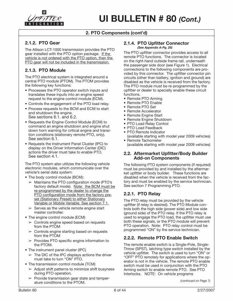
2.1.4. PTO Upfitter Connector (See Appendix A-Pg. 25) The PTO upfitter connector provides access to all remote PTO functions. The connector is located on the right-hand outside frame rail, underneath the passenger side door (see Figure �). Electrical connections to the following components are pro-vided by this connector. The upfitter connector pin circuits (other than battery, ignition and ground) are disabled as the vehicle is received from the factory. The PTO module must be re-programmed by the upfitter or dealer to specially enable these circuit functions. • Remote PTO Arming• Remote PTO Enable• Remote PTO Set• Remote Accelerator• Remote Engine Start• Remote Engine Shutdown• PTO Load Relay Control• PTO Load Feedback• PTO Remote Indicator (available starting with model year 2009 vehicles)• Remote Tachometer (available starting with model year 2009 vehicles)
2.2. Aftermarket Upfitter/Body Builder Add-on Components
The following PTO system components (if required) must be provided by and installed by the aftermar-ket upfitter or body builder. These functions are disabled when the vehicle is received from the fac-tory and must be enabled by the service technician. See section 7 Programming PTO.
2.2.1. PTO RelayThe PTO relay must be provided by the vehicle upfitter (if relay is desired). The PTO Module con-trols both the high side (power side) and low side (ground side) of the PTO relay. If the PTO relay is used to engage the PTO load, the upfitter must use both these signals, or the PTO module will prevent PTO operation. Note: PTO relay control must be programmed “ON” by the service technician.
2.2.2. Remote PTO Enable Switch The remote enable switch is a Single-Pole, Single-Throw (SPST), latching type switch installed by the vehicle upfitter. The switch is used to turn “ON” or “OFF” PTO remotely for applications where the op-erator is not in the vehicle. The remote PTO enable switch must be used in conjunction with the PTO Arming switch to enable remote PTO. See PTO Interlocks. NOTE: On vehicle programs
2.1.2. PTO GearThe Allison LCT-�000 transmission provides the PTO gear installed with the PTO option package. If the vehicle is not ordered with the PTO option, then the PTO gear will not be included in the transmission.
2.1.3. PTO ModuleThe PTO electrical system is integrated around a central PTO module (PTOM). The PTOM provides the following key functions:• Processes the PTO operator switch inputs and translates these inputs into an engine speed request to the engine control module (ECM). • Controls the engagement of the PTO load relay.• Process requests to the BCM and ECM to start and shutdown the engine. See sections 6.�. and 6.2.• Requests the Engine Control Module (ECM) to command an engine shutdown and engine shut down horn warning for critical engine and transi- tion conditions (stationary remote PTO, only). See section 6.�.• Requests the Instrument Panel Cluster (IPC) to display on the Driver Information Center (DIC) actions the driver must take to enable PTO. See section 4.�.
The PTO system also utilizes the following vehicle electronic modules, which communicate over the vehicle’s serial data system:• The body control module (BCM): ➢ Maintains the PTO configuration mode (PTO’s factory default mode). Note: the BCM must be
re-programmed by the dealer to change thePTO configuration mode from the factory pre-set (Stationary Preset) to either Stationary Variable or Mobile Variable. See section 7.�.
➢ Serves as the vehicle remote engine start master controller.• The engine control module (ECM) ➢ Controls engine speed based on requests from the PTOM ➢ Controls engine starting based on requests from the PTOM ➢Provides PTO specific engine information to the PTOM. • The instrument panel cluster (IPC) ➢ The DIC of the IPC displays actions the driver must take to turn “ON” PTO.• The transmission control module (TCM) ➢ Adjust shift patterns to minimize shift busyness during PTO operation. ➢ Provide transmission gear state and temper- ature conditions to the PTOM. (continued on Page 7)

7 of 44Bulletin 80 2/27/2007
UI BULLETIN # 80 (Cont.)
mote PTO enable and remote engine start switch. To initiate remote PTO operation the operator must first press and release the “Remote PTO Arming” switch, then with in 5 seconds push the “Remote PTO Enable” switch to turn “ON” PTO. If remotely starting the vehicle, press and release the “Remote PTO Arming” switch, then within 5 seconds push the “Remote Start” Switch. 2.2.5. Remote Engine Shutdown Switch The remote engine shutdown switch is a normally-closed (N.C.), momentary type switch installed by the vehicle upfitter. The PTO remote engine shut-down switch (or engine “KILL” switch) provides the operator a method for routine or for emergency shutdown the engine. PTO does not need to be operating for this switch to function.
2.2.6. Remote PTO Set Switch The remote PTO set switch input to the PTO module can be programmed to function as a Single-Pole, Double-Throw (SPDT) momentary or latching type switch installed by the vehicle upfitter. The switch is used to set the engine speed from a remote location outside the vehicle cab. The switch will not operate unless PTO is initially enabled.
2.2.7. Remote PTO Accelerator Sensor The remote PTO accelerator sensor is installed by the vehicle upfitter. The sensor is used to adjust the engine speed from a remote location outside the vehicle cab. The sensor will not operate unless PTO is initially enabled. The in-cab PTO switch SET-/RES+ and remote set switch will not function when the remote accelerator sensor is used.
prior to model years 2007 (GMT800), the load engage switch was used to supply voltage from the PTO relay switch contacts. When the switch is closed current will flow to the PTO solenoid. This function has been replaced by the “Remote PTO Enable” Switch. GM discourages upfitters from using a load engage switch because it will interfere with PTO module diagnostics intended to protect the operator.
Remote PTO enable switch requires an arming sequence prior to enabling PTO. To initiate remote PTO operation the operator must first press and release the “Remote Arming” switch, then within 5 seconds push the “Remote PTO Enable” switch to turn “ON” PTO. The PTO system will then enter standby mode. The PTO relay is energized and the engine RPM is increased to 850 RPM (Factor preset value). 2.2.3. Remote Engine Start SwitchThe remote engine start switch is a normally-open (N.O.), momentary type switch installed by the vehicle upfitter. The switch is used to start the en-gine from a remote location outside the vehicle cab. PTO does not need to be selected for this switch to operate. The remote starting switch must be used in conjunction with the Remote Arming switch to remotely start the engine. When remotely starting the vehicle, press and release the “Remote PTO Arming” switch, then within 5 seconds push the “Remote Start” Switch.
2.2.4. Remote Arming SwitchThe remote arming switch is a normally-open (N.O.), momentary type switch installed by the vehicle upfit-ter. The switch is used in conjunction with the re-
2. PTO Components (cont’d)
3. PTO Operation
The PTO Module (PTOM) is the control center of the PTO system. The PTOM monitors numerous engine and vehicle conditions which must be satis-fied before PTO can be enabled.
3.1. PTO Enabling Conditions3.1.1. Stationary PTO Enabling ConditionsTo engage stationary PTO operation, the following conditions must be met:
• The engine must be running.
• The vehicle cannot be moving and the parking brake must be set.
• The shift lever must be in PARK (P) or NEUTRAL (N).
• The brake pedal must not be pressed.
• The engine speed must be less than the maxi mum allowed PTO engage speed of �500 rpm. The PTO engage speed can be adjusted by a service technician.
For in-cab PTO operation:
Press and release the position on the PTO switch. The PTO LED light will blink fast until the PTO load becomes engaged. The LED light will then be on steady.
The and switch positions can then be used to establish the desired PTO operating speed.
(continued on Page 8)
8 of 44Bulletin 80 2/27/2007
3. PTO Operation
UI BULLETIN # 80 (Cont.)
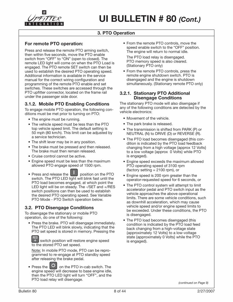
For remote PTO operation:Press and release the remote PTO arming switch, then within five seconds, move the PTO enable switch from “OFF” to “ON” (open to closed). The remote LED light will come on when the PTO Load is engaged. The PTO remote SET switch can then be used to establish the desired PTO operating speed. Additional information is available in the service manual for the correct wiring configuration and programming of the remote PTO enable and set switches. These switches are accessed through the PTO upfitter connector, located on the frame rail under the passenger side door.
3.1.2. Mobile PTO Enabling ConditionsTo engage mobile PTO operation, the following con-ditions must be met prior to turning on PTO:
• The engine must be running. • The vehicle speed must be less than the PTO
top vehicle speed limit. The default setting is 50 mph (80 km/h). This limit can be adjusted by a service technician.
• The shift lever may be in any position. • The brake must be pressed and then released. The brake must then remain released. • Cruise control cannot be active. • Engine speed must be less than the maximum allowed PTO engage speed of �500 rpm.
• Press and release the position on the PTO switch. The PTO LED light will blink fast until the PTO load becomes engaged, at which point the LED light will be on steady. The -/SET and +/RES switch positions can then be used to establish the desired PTO operating speed. See Variable PTO Mode - PTO Switch operation below.
3.2. PTO Disengage ConditionsTo disengage the stationary or mobile PTO operation, do one of the following:
• Press the brake. PTO will disengage immediately. The PTO LED will blink slowly, indicating that the PTO set speed is stored in memory. Pressing the
switch position will restore engine speed to the stored PTO set speed.
Note: In mobile PTO mode, PTO can be repro- grammed to re-engage at PTO standby speed after releasing the brake pedal.
• Press the on the PTO in-cab switch. The engine speed will decrease to base engine idle, then the PTO LED light will turn “OFF”, and the PTO load relay will disengage.
• From the remote PTO controls, move the speed enable switch to the “OFF” position. The engine will return to normal idle.
The PTO load relay is disengaged. PTO memory speed is also cleared. (Stationary PTO only)
• From the remote PTO controls, press the remote engine shutdown switch. PTO is disengaged and the engine is shutdown simultaneously. (Stationary remote PTO only)
3.2.1. Stationary PTO Additional Disengage Conditions
The stationary PTO mode will also disengage if any of the following conditions are detected by the vehicle electronics:
• Movement of the vehicle.
• The park brake is released.
• The transmission is shifted from PARK (P) or NEUTRAL (N) to DRIVE (D) or REVERSE (R).
• The PTO load becomes disengaged (this con-dition is indicated by the PTO load feedback changing from a high voltage {approx �2 Volts} to a low voltage {approx 0 Volts} while PTO is engaged).
• Engine speed exceeds the maximum allowed PTO operating speed of ��00 rpm (factory setting = 2�00 rpm), or
• Engine speed is 200 rpm greater than the operator-requested speed for 6 seconds, or
• The PTO control system will attempt to limit accelerator pedal and PTO switch input as the vehicle approaches the above operational limits. There are some vehicle conditions, such as downhill acceleration, which may cause vehicle speed and/or engine speed limits to be exceeded. Under these conditions, the PTO is disengaged.
• The PTO load becomes disengaged (this condition is indicated by the PTO load feed back changing from a high-voltage state {approximately �2 Volts} to a low-voltage state {approximately 0 Volts} while the PTO is engaged).
(continued on Page 9)

9 of 44Bulletin 80 2/27/2007
Instrument PanelCluster(I.P.C.)
Driver Information
Center(D.I.C.)
(continued on Page 10)
UI BULLETIN # 80 (Cont.)
Stationary PTO Mobile PTO
MY2007 - PTO: RELEASE ACCELERATOR(MY2008 - PTO: REDUCED VEHICLE SPEED
PTO: DISENGAGE CRUISE CONTROL
PTO: RELEASE BRAKE PTO: PRESS & RELEASE BRAKE
PTO: REDUCE ENGINE SPEED PTO: REDUCE ENGINE SPEED
PTO: SHIFT TO P OR N PTO: RELEASE BRAKE
– PTO: SET PARK BRAKE
Table 1
4.1. Driver Information Center (DIC) Warning Messages
If the PTO will not engage, one or more of the fol-lowing DIC messages may appear on the instru-ment panel cluster (IPC). To successfully engage PTO, the operator must take the action indicated, then again press and release the position of the PTO switch.
4. Driver Warnings
3. PTO Operation (cont’d)
3.2.2. Mobile PTO Additional Disengage Conditions
The mobile PTO mode will also disengage if the fol-lowing conditions are detected by the vehicle elec-tronics:
• Vehicle speed exceeds 50 mph (factory setting = 80 km/h).
• Engine speed exceeds the maximum allowed PTO operating speed of ��00 rpm (factory setting = 2�00 rpm).
• The PTO control system will attempt to limit accelerator pedal and PTO switch input as the vehicle approaches the above operational limits. There are some vehicle conditions, such as down hill acceleration, which may cause ve-hicle speed and/or engine speed limits to be exceeded. Under these conditions, PTO is disengaged.
• The PTO load becomes disengaged (this condition is indicated by the PTO load feedback changing from a high-voltage state {approx �2 Volts} to a low-voltage state {approx 0 Volts} while PTO is engaged).
In addition to these messages, the PTO switch LED will indicate when all conditions required to engage PTO have not been met. When enabling PTO, the LED will turn “ON”, then “OFF” after one second. Under normal operating conditions, the PTO LED will remain “ON” throughout the PTO operating cycle.
DIC PTO Messages
�0 of 44Bulletin 80 2/27/2007
(continued on Page 11)
UI BULLETIN # 80 (Cont.)
4.2. Prolonged or Extended PTO Operations
While operating your vehicle in stationary PTO mode, the Diesel Particulate Filter (DPF) will con-tinue to filter the exhaust and accumulate soot. The engine control system, depending on the speed and load being applied by the PTO, may not be able to generate enough energy or adequate heat needed to clean or regenerate the DPF. Continued operation under conditions that do not allow effective regeneration or cleaning will eventu-ally plug the DPF and result in reduced power. The
5. Engine Speed Control Modes
5.1. Preset PTO ModePreset PTO can only be used when the vehicle is not
moving. After the PTO in-cab switch position is pressed and released, the engine speed is initially set to a stand-by engine speed (850 rpm). Using Remote switch controls, by pressing and releasing the remote arming switch, then within five seconds, push the remote PTO enable switch to “ON” will also establish standby speed operation. This provides an initial start-up engine speed to match the engage-ment of the PTO load. The PTO standby engine speed can be reprogrammed to a higher speed by your dealer.
Pressing the switch position on the PTO in-cab switch or moving the remote PTO enable switch to “OFF” will return the engine speed back to normal idle. The PTO load relay is also disengaged.
Maximum PTO Operating Speed: During PTO opera-tion, the accelerator pedal can be pressed to adjust the engine speed. To protect the PTO from over-speed, the PTO system will disengage when the engine speed exceeds 2�00 rpm for longer than 6 seconds.
The Stationary PTO Mode provides both in-cab and remote controls. The in-cab controls are enabled as the factory preset. The remote controls are disabled. This factory preset configuration can also be repro-grammed to enable the remote controls, and disable the In-Cab PTO controls (i.e., PTO switch, accelera-tor pedal). See your dealer for more information.
5.1.1. In-Cab PTO Set Switch OperationThree factory pre-programmed engine speeds can be selected from the In-Cab PTO switch. • The first speed is selected when the PTO system is turned “ON”. This is the PTO Standby speed – 850 rpm. • The second engine speed – �250 rpm can now
be selected by depressing the portion of the switch. • The third engine speed – �700 rpm can be
selected by depressing the portion of the switch.
Each of these three speeds can be reprogrammed by a service technician to values other than the fac-tory settings.
• PTO ON: Pressing the position of the PTO switch will cause the engine to go to the PTO preset Standby speed – 850 rpm.
Note: Many applications just use “ON” and “OFF” for a single working speed. Since the PTO Standby speed is programmable, you can select the desired working speed and simply turn the system “ON” – to run at this speed and then turn it “OFF” again.
4. Driver Warnings (cont’d)
ENGINE POWER IS REDUCED Driver Information Center (DIC) message and Malfunction Indicator Lamp will be displayed, and dealer/retailer service will be required to return your vehicle to normal, full power operation. To prevent this from occurring, frequently monitor your vehicle during PTO operation, paying particular attention to the CLEAN EXHAUST FILTER SEE OWN-ER MANUAL NOW DIC warning message. If the DIC message is displayed during PTO operation, see Diesel Particulate Filter for information on how to clean or regenerate the DPF. Also see “Engine Shut-down Control” earlier in this section.
�� of 44Bulletin 80 �/�5/2008
UI BULLETIN # 80 (Cont.)
5. Engine Speed Control Modes (cont’d)
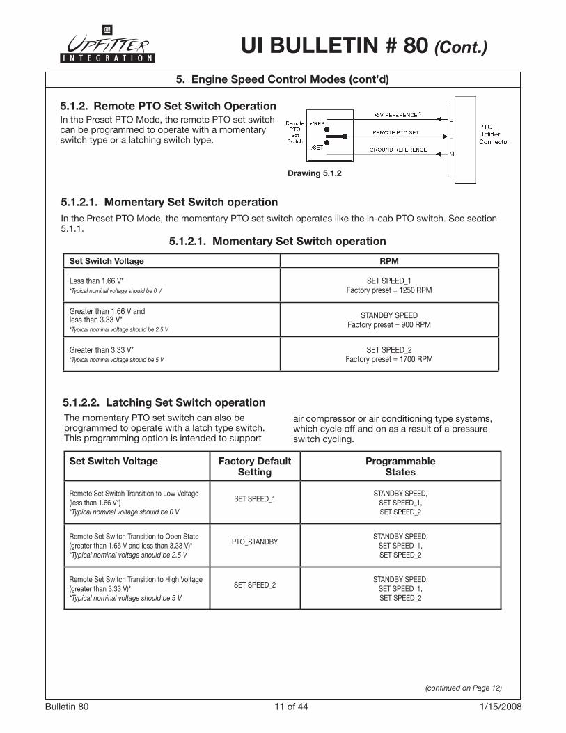
The momentary PTO set switch can also be programmed to operate with a latch type switch. This programming option is intended to support
Set Switch Voltage Factory DefaultSetting
ProgrammableStates
Remote Set Switch Transition to Low Voltage(less than �.66 V*)*Typical nominal voltage should be 0 V
SET SPEED_�STANDBY SPEED,
SET SPEED_�,SET SPEED_2
Remote Set Switch Transition to Open State(greater than �.66 V and less than �.�� V)**Typical nominal voltage should be 2.5 V
PTO_STANDBYSTANDBY SPEED,
SET SPEED_�,SET SPEED_2
Remote Set Switch Transition to High Voltage(greater than �.�� V)**Typical nominal voltage should be 5 V
SET SPEED_2STANDBY SPEED,
SET SPEED_�,SET SPEED_2
5.1.2.2. Latching Set Switch operationair compressor or air conditioning type systems, which cycle off and on as a result of a pressure switch cycling.
Set Switch Voltage RPM
Less than �.66 V**Typical nominal voltage should be 0 V
SET SPEED_�Factory preset = �250 RPM
Greater than �.66 V and less than �.�� V**Typical nominal voltage should be 2.5 V
STANDBY SPEEDFactory preset = 900 RPM
Greater than �.�� V**Typical nominal voltage should be 5 V
SET SPEED_2Factory preset = �700 RPM
5.1.2.1. Momentary Set Switch operation
5.1.2.1. Momentary Set Switch operationIn the Preset PTO Mode, the momentary PTO set switch operates like the in-cab PTO switch. See section 5.�.�.
5.1.2. Remote PTO Set Switch OperationIn the Preset PTO Mode, the remote PTO set switch can be programmed to operate with a momentary switch type or a latching switch type.
Drawing 5.1.2
(continued on Page 12)
�2 of 44Bulletin 80 2/27/2007
UI BULLETIN # 80 (Cont.)
5. Engine Speed Control Modes (cont’d)
(continued on Page 13)
Up
fitt
er C
onn
ecto
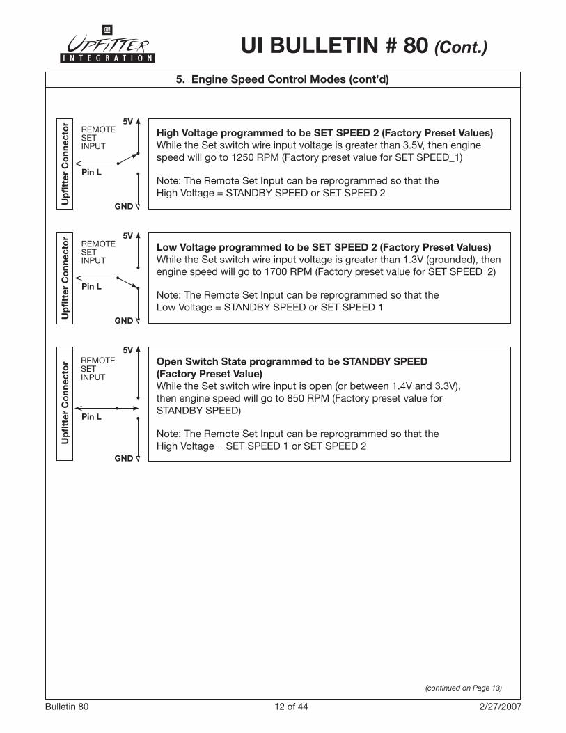
r Open Switch State programmed to be STANDBY SPEED (Factory Preset Value)While the Set switch wire input is open (or between �.4V and �.�V), then engine speed will go to 850 RPM (Factory preset value for STANDBY SPEED)
Note: The Remote Set Input can be reprogrammed so that the High Voltage = SET SPEED � or SET SPEED 2
5V
GND
REMOTESETINPUT
Pin L
Up
fitt
er C
onn
ecto
r
Low Voltage programmed to be SET SPEED 2 (Factory Preset Values)While the Set switch wire input voltage is greater than �.�V (grounded), then engine speed will go to �700 RPM (Factory preset value for SET SPEED_2)
Note: The Remote Set Input can be reprogrammed so that the Low Voltage = STANDBY SPEED or SET SPEED �
5V
GND
REMOTESETINPUT
Pin L
Up
fitt
er C
onn
ecto
r
High Voltage programmed to be SET SPEED 2 (Factory Preset Values)While the Set switch wire input voltage is greater than �.5V, then engine speed will go to �250 RPM (Factory preset value for SET SPEED_�)
Note: The Remote Set Input can be reprogrammed so that the High Voltage = STANDBY SPEED or SET SPEED 2
5V
GND
REMOTESETINPUT
Pin L
�� of 44Bulletin 80 2/27/2007
UI BULLETIN # 80 (Cont.)
5. Engine Speed Control Modes (cont’d)
Third Gear
Fourth Gear
Fifth GearSixth Gear
0
250
500
750
1000
1250
1500
1750
2000
2250
2500
2750
20 30 40 50 60 70 80 90
Speed MPH
Third Gear Fourth Gear Fifth Gear Sixth Gear
RPM Needed to Hold Vehicle SpeedNormal Driving – No Load
Approximated Values – Unofficial Information
RP
M
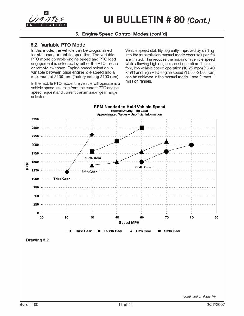
5.2. Variable PTO ModeIn this mode, the vehicle can be programmed for stationary or mobile operation. The variable PTO mode controls engine speed and PTO load engagement is selected by either the PTO in-cab or remote switches. Engine speed selection is variable between base engine idle speed and a maximum of ��00 rpm (factory setting 2�00 rpm).
In the mobile PTO mode, the vehicle will operate at a vehicle speed resulting from the current PTO engine speed request and current transmission gear range selected.
Vehicle speed stability is greatly improved by shifting into the transmission manual mode because upshifts are limited. This reduces the maximum vehicle speed while allowing high engine speed operation. There-fore, low vehicle speed operation (�0-25 mph) (�6-40 km/h) and high PTO engine speed (�,500 -2,000 rpm) can be achieved in the manual mode � and 2 trans-mission ranges.
(continued on Page 14)
Drawing 5.2
�4 of 44Bulletin 80 2/27/2007
UI BULLETIN # 80 (Cont.)
5. Engine Speed Control Modes (cont’d)
(continued on Page 15)
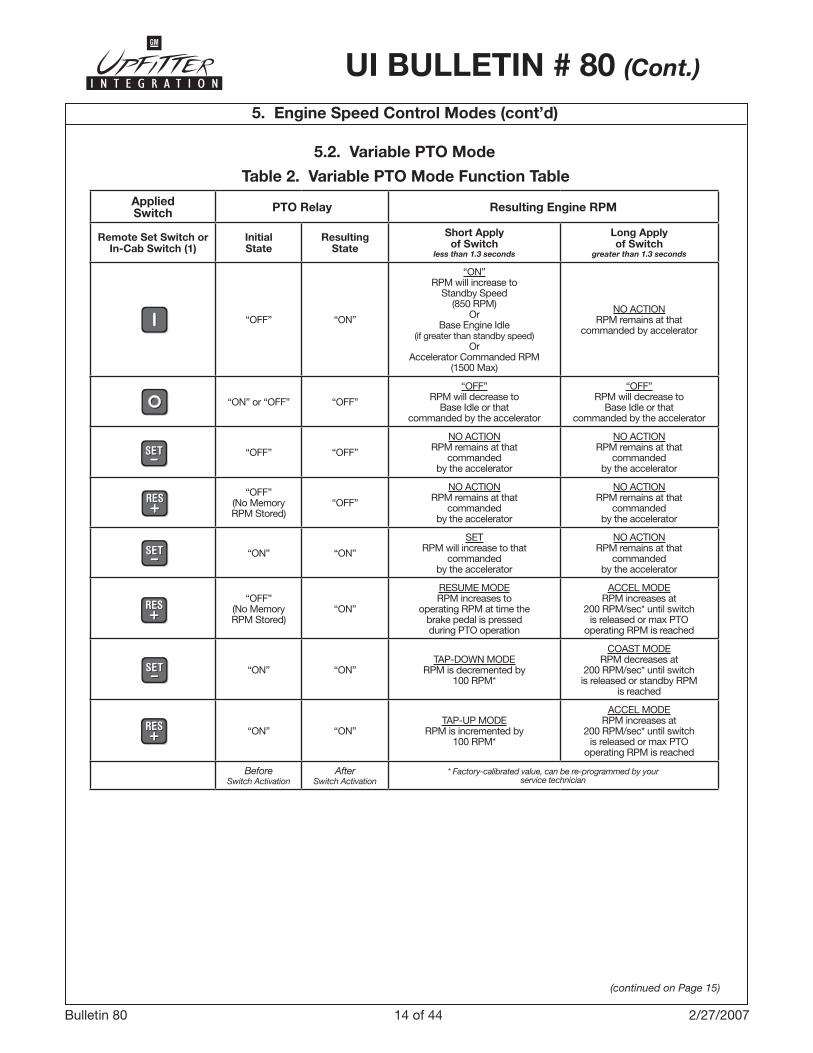
5.2. Variable PTO Mode
AppliedSwitch PTO Relay Resulting Engine RPM
Remote Set Switch or In-Cab Switch (1)
Initial State
Resulting State
Short Apply of Switch
less than 1.3 seconds
Long Apply of Switch
greater than 1.3 seconds
“OFF” “ON”
“ON”RPM will increase to
Standby Speed(850 RPM)
OrBase Engine Idle
(if greater than standby speed)Or
Accelerator Commanded RPM (�500 Max)
NO ACTIONRPM remains at that
commanded by accelerator
“ON” or “OFF” “OFF”
“OFF”RPM will decrease to
Base Idle or thatcommanded by the accelerator
“OFF”RPM will decrease to
Base Idle or thatcommanded by the accelerator
“OFF” “OFF”
NO ACTIONRPM remains at that
commanded by the accelerator
NO ACTIONRPM remains at that
commanded by the accelerator
“OFF”(No MemoryRPM Stored)
“OFF”
NO ACTIONRPM remains at that
commanded by the accelerator
NO ACTIONRPM remains at that
commanded by the accelerator
“ON” “ON”
SETRPM will increase to that
commanded by the accelerator
NO ACTIONRPM remains at that
commanded by the accelerator
“OFF”(No MemoryRPM Stored)
“ON”
RESUME MODERPM increases to
operating RPM at time the brake pedal is pressed during PTO operation
ACCEL MODERPM increases at
200 RPM/sec* until switchis released or max PTO
operating RPM is reached
“ON” “ON”TAP-DOWN MODE
RPM is decremented by �00 RPM*
COAST MODERPM decreases at
200 RPM/sec* until switchis released or standby RPM
is reached
“ON” “ON”TAP-UP MODE
RPM is incremented by �00 RPM*
ACCEL MODERPM increases at
200 RPM/sec* until switchis released or max PTO
operating RPM is reached
BeforeSwitch Activation
AfterSwitch Activation
* Factory-calibrated value, can be re-programmed by your service technician
Table 2. Variable PTO Mode Function Table

�5 of 44Bulletin 80 2/27/2007
UI BULLETIN # 80 (Cont.)
5. Engine Speed Control Modes (cont’d)
5.2.1. In-cab PTO Switch OperationIn the variable PTO mode, the in-cab PTO switch shall operate as follows:ON:To engage PTO, press and release the in-cab switch position. The vehicle will increase engine speed to a factory preset engine speed (850 rpm). This PTO stand-by speed is not intended to be an operational PTO speed, but allows the engagement of the PTO at lower initial start-up rpm to match with the engagement of the PTO load relay.
The initial stand-by speed can be adjusted by hold-ing the accelerator to the desired engine speed, then
pressing and releasing the in-cab PTO switch position. The current engine speed will become the new stand-by speed for the duration of the PTO “ON” cycle. This adjustment can only be done once at the initial engagement of PTO. The initial stand-by speed adjustment must be between engine base idle speed and �500 rpm (maximum PTO engage speed). The new standby speed is not retained after PTO is disabled (or turned off).
OFF:
Press and release the in-cab switch position or push the remote enable switch to “OFF” to dis-engage PTO. The engine speed will be reduced to the base idle speed and the PTO load relay will be disengaged.
SET:
Press and hold the accelerator to obtain the desired engine speed, then press and release the
in-cab position of the PTO switch. The current engine speed will be maintained. This action can be repeated as desired to a higher rpm value. The PTO set speed cannot exceed 2�00 rpm (factory preset, max setting ��00 rpm).
TAP-DOWN:
Press and release the in-cab switch position on the PTO switch to reduce the engine speed by increments of �00 rpm.
COAST:
Press and hold the in-cab switch position on the PTO switch to reduce the rpm by 200 rpm per second until the desired engine speed is reached or
until the initial PTO standby speed is reached.
RESUME:
When a PTO set speed has been achieved, press and release the brake pedal. Engine speed will reduce to basic idle speed. The PTO LED will blink slowly indicating the previous PTO set speed has been retained in memory.
Press and release the in-cab switch position to resume the previous PTO set speed. The PTO set speed cannot exceed 2�00 rpm (factory preset, max setting ��00 rpm).
TAP-UP:
Press and release the in-cab position to increase the engine speed by increments of �00 rpm.
ACCEL:
Press and hold the in-cab position to increase the rpm by 200 rpm per second until the desired engine speed is reached or until the maximum allow-able PTO set speed is reached.
5.2.2. Remote PTO Switch Operation In the variable PTO mode, the remote PTO switch shall operate as follows:
Remote PTO Enable (ON/OFF Switch)
To engage PTO, press and release the remote PTO arming switch, then within five seconds, move the PTO enable switch from “OFF” to “ON” (open to closed). The vehicle will increase engine speed to a factory preset engine speed (800 rpm). This PTO stand-by speed is not intended to be an operational PTO speed, but allows the engagement of the PTO at lower initial start-up rpm to match with the en-gagement of the PTO load relay.
Remote PTO SET Switch
In the variable PTO mode, the remote PTO set switch can be programmed to operate as a momentary switch, only. The switch operates the same way as the in-cab PTO switch. See section 5.2, Table 2.
�6 of 44Bulletin 80 2/27/2007
UI BULLETIN # 80 (Cont.)
6.1. Remote Engine ShutdownThe vehicle’s PTO system allows for remote engine shutdown while operating in the stationary PTO mode. This feature has the following functions:
• Engine shutdown using the operator remote switch: The vehicle wiring system provides remote engine shutdown switch connections, which is accessed through the PTO upfitter connector.
• Timed auto-engine shutdown: The timed auto-engine shutdown feature provides the means to shut down the engine automatically after a predefined time. PTO must be opera-tional for this function to be active.
• Engine shutdown based on critical engine conditions: The engine will be shutdown when PTO is operating if a critical engine condition is detected by the vehicle system (i.e., low oil, low oil pressure, hot engine, hot transmission, low fuel, diesel particulate filter regeneration). If PTO operation is continued when critical engine conditions are present, a horn chirp warning will occur after 2 to 5 min-utes. The engine will be shutdown 2 minutes after the horn warning. The operator can re-start the engine with the ignition key or with the PTO remote engine start controls. The above horn warning and engine shutdown will again occur if the critical engine condition is still present.
6.2. Remote Engine StartThe vehicle’s PTO system allows the engine to be remotely started while operating in the stationary PTO mode. The vehicle wiring system provides for connections to a remote engine start arming switch and remote starting switch. These connections are accessed through the upfitter connector.
The remote start function is initiated by a sequence of switch actions, in addition to several vehicle con-ditions.
The following conditions must be met before at-tempting to remote start the engine. The vehicle ignition key can be in any position or removed from the ignition.
• The vehicle must be configured for stationary PTO operation by the dealer.
• The parking brake must be set. • The transmission shift lever must be in PARK (P). • The vehicle hood must be closed.
Once the above conditions are met, to continue with the remote start, do the following using the remote PTO controls:
�. Press and release the remote start arming switch.
2. Within five seconds of releasing the remote start arming switch, press and hold the remote engine start switch for about two seconds until the engine starts. Release the remote engine start switch.
To enable normal PTO operation following a remote start event, press and release the arming switch. Then within five seconds, the PTO remote enable switch must be toggled from “OFF” to “ON”. The PTO system will then elevate engine rpm to standby speed and engage the PTO load. Press the remote PTO -/SET or +/RES switch to elevate PTO to the desired engine operating speed.
See your dealer for additional information on the PTO system and settings.
6. Remote Engine Start and Shutdown Control
�7 of 44Bulletin 80 �/�5/2008
UI BULLETIN # 80 (Cont.)
(continued on Page 18)
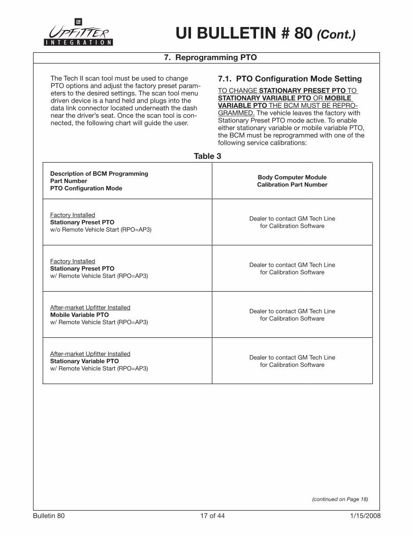
7. Reprogramming PTO
The Tech II scan tool must be used to change PTO options and adjust the factory preset param-eters to the desired settings. The scan tool menu driven device is a hand held and plugs into the data link connector located underneath the dash near the driver’s seat. Once the scan tool is con-nected, the following chart will guide the user.
7.1. PTO Configuration Mode SettingTO CHANGE STATIONARY PRESET PTO TO STATIONARY VARIABLE PTO OR MOBILE VARIABLE PTO THE BCM MUST BE REPRO-GRAMMED. The vehicle leaves the factory with Stationary Preset PTO mode active. To enable either stationary variable or mobile variable PTO, the BCM must be reprogrammed with one of the following service calibrations:
Table 3
Description of BCM ProgrammingPart Number PTO Configuration Mode
Body Computer ModuleCalibration Part Number
Factory InstalledStationary Preset PTOw/o Remote Vehicle Start (RPO=AP�)
Dealer to contact GM Tech Line for Calibration Software
Factory InstalledStationary Preset PTOw/ Remote Vehicle Start (RPO=AP�)
Dealer to contact GM Tech Line for Calibration Software
After-market Upfitter InstalledMobile Variable PTOw/ Remote Vehicle Start (RPO=AP�)
Dealer to contact GM Tech Line for Calibration Software
After-market Upfitter InstalledStationary Variable PTOw/ Remote Vehicle Start (RPO=AP�)
Dealer to contact GM Tech Line for Calibration Software

�8 of 44Bulletin 80 2/27/2007
(continued on Page 19)
7. Reprogramming PTO
7.2. PTO Factory Default Settings Table 4
PTO In-cab Control ENABLED DISABLED ENABLED
PTO Remote Control DISABLED DISABLED ENABLED
Type of Set Switch MOMENTARY MOMENTARY LATCHING
Press “ON” then go to Preset � Speed
DISABLED DISABLED ENABLED
Remote Engine Start DISABLED DISABLED ENABLED
Remote Engine Shutdown DISABLED DISABLED ENABLED
Load Feedback DISABLED DISABLED ENABLED
Engage Relay DISABLED DISABLED ENABLED
Keep Relay engage during braking DISABLED DISABLED ENABLED
Action after brake is released RETURN TOBASE IDLE RPM
RETURN TO BASE IDLE RPM
RETURN TO STANDBY RPM
Auto Engine Shutdown Timer ENABLED DISABLED ENABLED
Engine Shutdown due to Critical Engine Condition
DISABLED DISABLED ENABLED
Engine Shutdown warning DISABLED DISABLED ENABLED
Set Low Fuel level for Engine Shutdown
�5% 0 25%
Engine Run Time While PTO is Active - Timer
7 hours 4 minutes 7 hours
Max. PTO Engine Speed �800 950 ��00
Max. PTO Engage Speed �500 RPM 500 RPM �800 RPM
Programmable Parameters Factory Setting Minimum Value Maximum ValueSTATIONARY PRESET
STATIONARY VARIABLE
MOBILE VARIABLE
STATIONARY PRESET
PTO Type(Available in MY2009, BCM will no longer require programming)
Once the mode of operation is selected the Current PTO Settings menu will appear with the adjustable parameters for the current mode.
This screen allows the user to increase or de-crease engine RPM values using the INCREASE and DECREASE buttons. If the Engine Fault Shut-down feature is selected, the YES or NO Buttons will determine if this feature is enabled.
Important: Please be aware that PTO high idle set-tings must be reprogrammed in the event that the PTOM is replaced. It may be advisable to provide the PTOM settings information to the customer in case the PTOM requires servicing during some point in the life of the vehicle.
After all the settings are adjusted, the user will press the REPROGRAM button and the Current PTO Set-tings menu will appear with the changes. The igni-tion must be turned “OFF” for �0 seconds to ensure that the program values are stored in the PTOM.
UI BULLETIN # 80 (Cont.)

�9 of 44Bulletin 80 2/27/2007
UI BULLETIN # 80 (Cont.)
7. Reprogramming PTO (cont’d)
Table 4 (cont’d)
PTO Standby RPM 850
500 RPMNormal engine idlewill not override if
higher than StandbySpeed
��00
PTO Preset � Speed �250
500 RPMPTO Set Speed �
cannot be set belowPTO Standby speed
��00
PTO Preset 2 Speed �700
500 RPMPTO Set Speed 2
cannot be set belowPTO Standby speed
��00
Maximum PTO Operating Speed 2�00 RPM 500 RPM ��00 RPM
Tap Step �00 RPM 4 RPM 500 RPM
Ramp Rate 200 RPM 4 RPM �000 RPM
Maximum Vehicle Speed �29 km/h �0 km/h �29 km/h
Minimum Remote AcceleratorVoltage
0.25 V 0.0 2.5 V
Maximum Remote AcceleratorVoltage
4.75 V 2.5 5.0 V
Remote Set Switch Transition toLow Voltage (<�.66 V)
SET_SPEED �
STANDBY SPEED
SET_SPEED �
SET_SPEED 2
Remote Set Switch Transition toOpen State (between >�.66 V and <�.�� V)
PTO_STANDBY STANDBY SPEED
SET_SPEED �
SET_SPEED 2
Remote Set Switch Transition toHigh Voltage <�.�� V)
SET_SPEED 2 STANDBY SPEED
SET_SPEED �
SET_SPEED 2
Programmable Parameters Factory Setting Minimum Value Maximum ValueSTATIONARY PRESET
STATIONARY VARIABLE
MOBILE VARIABLE
STATIONARY PRESET
PTO Type(Available in MY2009, BCM will no longer require programming)
If the PTO factory preset parameters do not match the settings described above, then they may have already been altered in order to satisfy the requirements of the installed PTO system and body equipment.
20 of 44Bulletin 80 2/27/2007
UI BULLETIN # 80 (Cont.)
(continued on Page 21)
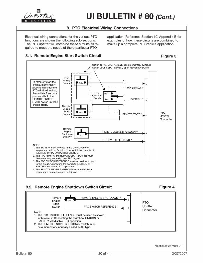
8. PTO Electrical Wiring Connections
Electrical wiring connections for the various PTO functions are shown the following sub-sections. The PTO upfitter will combine these circuits as re-quired to meet the needs of there particular PTO
application. Reference Section �0, Appendix B for examples of how these circuits are combined to make up a complete PTO vehicle application.
8.2. Remote Engine Shutdown Switch Circuit Figure 4
Note:1. The PTO SWITCH REFERENCE must be used as shown in this circuit. Connecting the switch to IGNITION or BATTERY will disable PTO operation.2. The REMOTE ENGINE SHUTDOWN switch must be a momentary, normally closed (N.C.) type.
PTO SWITCH REFERENCE
PTOUpfitterConnector
RemoteEngineStart
Switch
N.C. B
F
REMOTE ENGINE SHUTDOWN (1)
8.1. Remote Engine Start Switch Circuit Figure 3
To remotely start theengine, momentarilypress and release thePTO ARMING switch,then within 5 secondspress and hold theREMOTE ENGINESTART switch until theengine starts.
PTOArmingSwitch
RemoteEngineStart
SwitchN.O.
N.O.
PTO ARMING (2)
BATTERY (1)
REMOTE START (2) PTOUpfitterConnector
P
K
A
Note:1. The BATTERY must be used in this circuit. Remote engine start will not function if the switch is connected to IGNITION or PTO SWITCH REFERENCE.2. The PTO ARMING and REMOTE START switches must be momentary, normally open (N.O.) types.3. The PTO SWITCH REFERENCE must be used as shown in this circuit. Connecting the switch to IGNITION or BATTERY will disable PTO operation.4. The REMOTE ENGINE SHUTDOWN switch must be a momentary, normally closed (N.C.) type.
B
F
REMOTE ENGINE SHUTDOWN (3)
PTO SWITCH REFERENCE*
N.C.
RemoteEngine
ShutdownSwitch (4)
N.O.
N.O.
PTOArm-Start
Switch
Option 1: Two-SPST normally open momentary switchesOption 2: One-SPDT normally open momentary switch
2� of 44Bulletin 80 �/�5/2008
UI BULLETIN # 80 (Cont.)
8. PTO Electrical Wiring Connections (cont’d)
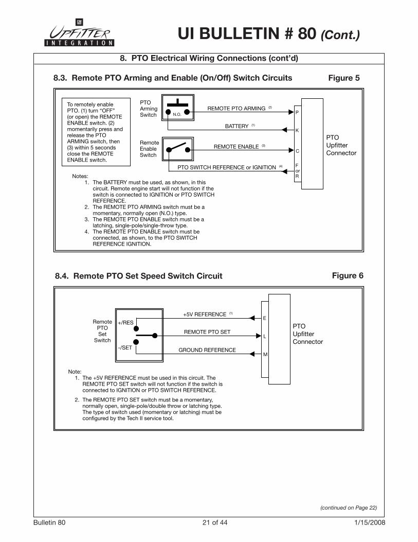
8.3. Remote PTO Arming and Enable (On/Off) Switch Circuits Figure 5
To remotely enablePTO. (1) turn “OFF”(or open) the REMOTEENABLE switch. (2)momentarily press andrelease the PTOARMING switch, then(3) within 5 secondsclose the REMOTEENABLE switch.
PTOArmingSwitch
RemoteEnableSwitch
N.O.REMOTE PTO ARMING (2)
PTOUpfitterConnector
ForRNotes:
1. The BATTERY must be used, as shown, in this circuit. Remote engine start will not function if the switch is connected to IGNITION or PTO SWITCH REFERENCE. 2. The REMOTE PTO ARMING switch must be a momentary, normally open (N.O.) type. 3. The REMOTE PTO ENABLE switch must be a latching, single-pole/single-throw type. 4. The REMOTE PTO ENABLE switch must be connected, as shown, to the PTO SWITCH REFERENCE IGNITION.
P
K
C
BATTERY (1)
REMOTE ENABLE (3)
PTO SWITCH REFERENCE or IGNITION (4)
(continued on Page 22)
8.4. Remote PTO Set Speed Switch Circuit Figure 6
Note: 1. The +5V REFERENCE must be used in this circuit. The
REMOTE PTO SET switch will not function if the switch is connected to IGNITION or +12V SWITCH REFERENCE.
2. The REMOTE PTO SET switch must be a momentary normal open single-pole / double-through or latching type, The Type of switch used must be configured by the Tech II service tool. Confer with dealership or your upfitter for more information. Also reference section TBD.
REMOTE PTO SET C
PTO Upfitter Connector
+5V REFERENCE (1)
GROUND REFERENCE
+/RES
-/SET
Remote PTO Set
Switch
E
M
RemotePTOSet
Switch
+5V REFERENCE (1)
PTOUpfitterConnector
E
M
Note: 1. The +5V REFERENCE must be used in this circuit. The REMOTE PTO SET switch will not function if the switch is connected to IGNITION or PTO SWITCH REFERENCE.
2. The REMOTE PTO SET switch must be a momentary, normally open, single-pole/double throw or latching type. The type of switch used (momentary or latching) must be configured by the Tech II service tool.
+/RES
-/SET
REMOTE PTO SET
GROUND REFERENCE
L
22 of 44Bulletin 80 �/�5/2008
UI BULLETIN # 80 (Cont.)
8. PTO Electrical Wiring Connections (cont’d)
(continued on Page 23)
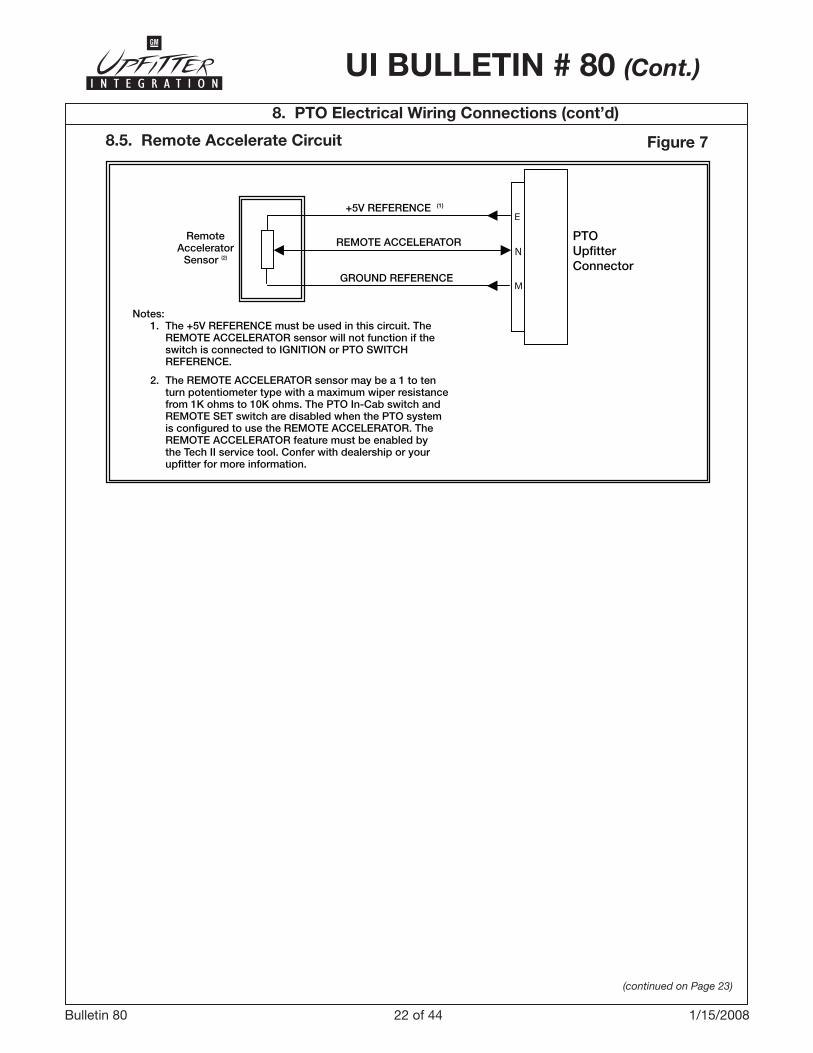
8.5. Remote Accelerate Circuit Figure 7
RemoteAccelerator
Sensor (2)
+5V REFERENCE (1)
PTOUpfitterConnector
Notes: 1. The +5V REFERENCE must be used in this circuit. The REMOTE ACCELERATOR sensor will not function if the switch is connected to IGNITION or PTO SWITCH REFERENCE.
2. The REMOTE ACCELERATOR sensor may be a 1 to ten turn potentiometer type with a maximum wiper resistance from 1K ohms to 10K ohms. The PTO In-Cab switch and REMOTE SET switch are disabled when the PTO system is configured to use the REMOTE ACCELERATOR. The REMOTE ACCELERATOR feature must be enabled by the Tech II service tool. Confer with dealership or your upfitter for more information.
E
REMOTE ACCELERATOR
GROUND REFERENCEM
N

2� of 44Bulletin 80 2/27/2007
UI BULLETIN # 80 (Cont.)
8. PTO Electrical Wiring Connections (cont’d)
(continued on Page 24)
8.6. PTO Load Relay and Load Feedback Circuits Figure 8
N.O.
(1)
(2)
Battery (10 Amps Max) or Ignition (10 Amps Max)
PTOUpfitterConnector
Notes: 1. Optional location of remote PTO lamp connection for MY2007 and MY2008 vehicles. This option will indicate when PTO hydraulic system detects the PTO hydraulic pump is providing hydraulic fluid pressure. This confirms the PTO is engaged and operating.
2. Optional location of remote PTO lamp connection for MY2007 and MY2008 vehicles. This option indicates when the PTO pump has been energized.
K
J
H
PTO LOAD RELAY HI
PTO LOAD RELAY LO
PTO Load Feedback
Power Ground
PTOLoadRelay
PTOControlSolenoid
OptionalRemote PTO Lampconnections
HydraulicPressureSwitch
(optional)
G
D

24 of 44Bulletin 80 2/27/2007
UI BULLETIN # 80 (Cont.)
8. PTO Electrical Wiring Connections (cont’d)
8.7. Remote PTO Indicator Circuit (MY2009) Figure 9
Note: Remote PTO Lamp feature is available starting with MY2009 vehicles
PTOUpfitterConnector
REMOTE PTO LAMP OUTPUTS
DPOWER GROUND
Remote PTO Lamp
8.8. Remote Tachometer Circuit (MY2009) Figure 10
Note: Remote Tachometer feature is available starting with MY2009 vehicles
PTOUpfitterConnector
S
D
IGNITION
TACHOMETER OUTPUT
POWER GROUND
R

25 of 44Bulletin 80 2/27/2007
UI BULLETIN # 80 (Cont.)
9. APPENDIX A: Upfitter Mating Connector Connector (cont’d)
(continued on Page 26)
9.1. Connector Components Table 6
X124 Engine Harness to PTO Jumper Harness (PTO)
TRUCK SIDE
BODY BUILDER “CAP” (Terminals & Seals required)
Connector Part Information
• OEM: �5�2686� • Service: �5�06�8� • Description: �6-Way F GT �50 Sealed (BK)
Connector Part Information
• OEM: �5�26868 • Service: �5�06�64 • Description: �6-Way M GT �50 Sealed (BK)
Part Number Type Description
TerminalSeals, andLocks
�5�58785 Lock Purple Secondary Lock
�5�66060 Seal Blue Individual Loose Cable Seal
�5�05�7� Seal Green Cable Cavity Cavity Plug
�5�6602� Seal White Individual Loose Cable Seal
�5�26268 TerminalMale GT �50 Tin Plated Terminal, Cable Range 0.50 - 0.�5 mm2, Cable Insulation Range �.85 - �.20 mm
�5�26269 TerminalMale GT �50 Tin Plated Terminal, Cable Range �.00 - 0.75 mm2, Cable Insulation Range 2.25 - �.70 mm
26 of 44Bulletin 80 2/27/2007
UI BULLETIN # 80 (Cont.)
9. APPENDIX A: Upfitter Mating Connector (cont’d)
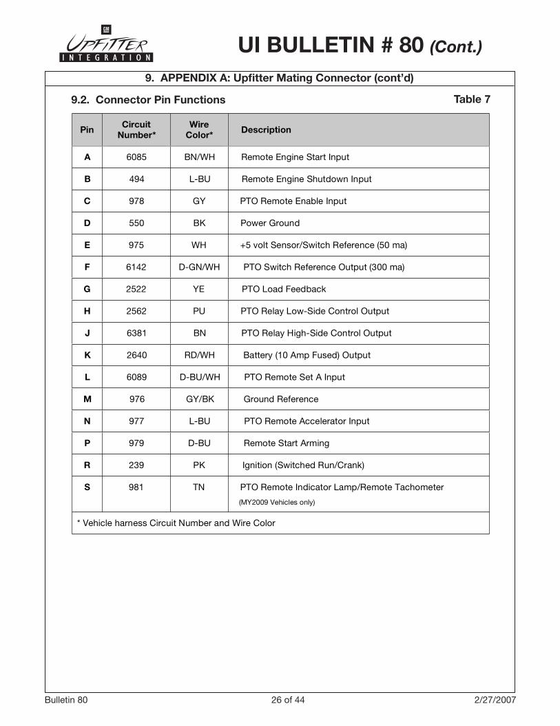
9.2. Connector Pin Functions Table 7
Pin CircuitNumber*
WireColor* Description
A 6085 BN/WH Remote Engine Start Input
B 494 L-BU Remote Engine Shutdown Input
C 978 GY PTO Remote Enable Input
D 550 BK Power Ground
E 975 WH +5 volt Sensor/Switch Reference (50 ma)
F 6142 D-GN/WH PTO Switch Reference Output (300 ma)
G 2522 YE PTO Load Feedback
H 2562 PU PTO Relay Low-Side Control Output
J 6381 BN PTO Relay High-Side Control Output
K 2640 RD/WH Battery (10 Amp Fused) Output
L 6089 D-BU/WH PTO Remote Set A Input
M 976 GY/BK Ground Reference
N 977 L-BU PTO Remote Accelerator Input
P 979 D-BU Remote Start Arming
R 239 PK Ignition (Switched Run/Crank)
S 981 TN PTO Remote Indicator Lamp/Remote Tachometer
(MY2009 Vehicles only)
* Vehicle harness Circuit Number and Wire Color
27 of 44Bulletin 80 2/27/2007
UI BULLETIN # 80 (Cont.)
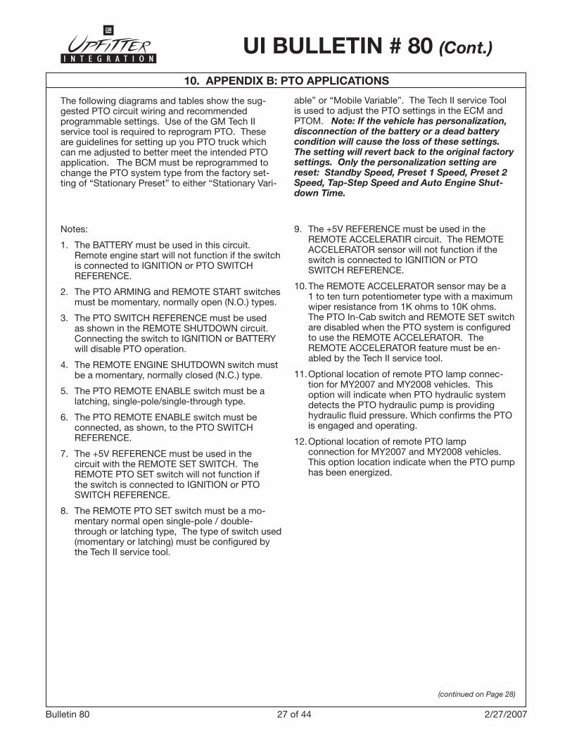
10. APPENDIX B: PTO APPLICATIONS
The following diagrams and tables show the sug-gested PTO circuit wiring and recommended programmable settings. Use of the GM Tech II service tool is required to reprogram PTO. These are guidelines for setting up you PTO truck which can me adjusted to better meet the intended PTO application. The BCM must be reprogrammed to change the PTO system type from the factory set-ting of “Stationary Preset” to either “Stationary Vari-
able” or “Mobile Variable”. The Tech II service Tool is used to adjust the PTO settings in the ECM and PTOM. Note: If the vehicle has personalization, disconnection of the battery or a dead battery condition will cause the loss of these settings. The setting will revert back to the original factory settings. Only the personalization setting are reset: Standby Speed, Preset 1 Speed, Preset 2 Speed, Tap-Step Speed and Auto Engine Shut-down Time.
(continued on Page 28)
Notes: �. The BATTERY must be used in this circuit.
Remote engine start will not function if the switch is connected to IGNITION or PTO SWITCH REFERENCE.
2. The PTO ARMING and REMOTE START switches
must be momentary, normally open (N.O.) types. �. The PTO SWITCH REFERENCE must be used
as shown in the REMOTE SHUTDOWN circuit. Connecting the switch to IGNITION or BATTERY will disable PTO operation.
4. The REMOTE ENGINE SHUTDOWN switch must
be a momentary, normally closed (N.C.) type. 5. The PTO REMOTE ENABLE switch must be a
latching, single-pole/single-through type. 6. The PTO REMOTE ENABLE switch must be
connected, as shown, to the PTO SWITCH REFERENCE.
7. The +5V REFERENCE must be used in the
circuit with the REMOTE SET SWITCH. The REMOTE PTO SET switch will not function if the switch is connected to IGNITION or PTO SWITCH REFERENCE.
8. The REMOTE PTO SET switch must be a mo-
mentary normal open single-pole / double-through or latching type, The type of switch used (momentary or latching) must be configured by the Tech II service tool.
9. The +5V REFERENCE must be used in the REMOTE ACCELERATIR circuit. The REMOTE ACCELERATOR sensor will not function if the switch is connected to IGNITION or PTO SWITCH REFERENCE.
�0. The REMOTE ACCELERATOR sensor may be a
� to ten turn potentiometer type with a maximum wiper resistance from �K ohms to �0K ohms. The PTO In-Cab switch and REMOTE SET switch are disabled when the PTO system is configured to use the REMOTE ACCELERATOR. The REMOTE ACCELERATOR feature must be en-abled by the Tech II service tool.
��. Optional location of remote PTO lamp connec-
tion for MY2007 and MY2008 vehicles. This option will indicate when PTO hydraulic system detects the PTO hydraulic pump is providing hydraulic fluid pressure. Which confirms the PTO is engaged and operating.
�2. Optional location of remote PTO lamp
connection for MY2007 and MY2008 vehicles. This option location indicate when the PTO pump has been energized.

28 of 44Bulletin 80 2/27/2007
UI BULLETIN # 80 (Cont.)
(continued on Page 29)
FACTORY PRESET PARAMETERSPTO TYPE Programmable
ParametersFactorySettings
Minimum Value
Maximum ValueStationary Mobile
nSet Low Fuel Level for
Engine Shutdown �5% 0 25%
nEngine Run Time WhilePTO is Active - Timer 7 Hours 4 Minutes 7 Hours
n n Max. PTO Engine Speed 2�00 950 ��00
n n Max. PTO Engage Speed �500 RPM 680 RPM �800 RPM
n n PTO Standby RPM 850
Normal engine idle will override
if higher than Standby Speed
��00
n PTO Preset � Speed �250
680 RPM PTO Set Speed �
cannot be set below PTO
Standby Speed
��00
n
PTO Preset 2 Speed
�700
680 RPM PTO Set Speed 2
cannot be set below PTO
Standby Speed
��00
n n Tap Step �00 RPM 4 RPM 500 RPM
n n Ramp Rate 200 RPM 4 RPM �000 RPM
n Maximum Vehicle Speed �29 km/h �0 km/h �29 km/h
Remote Accelerator Sensor Min./max. Voltage Settings
nMinimum Remote
Accelerator Voltage 0.25V 0.0 2.5V
nMaximum RemoteAccelerator Voltage 4.75V 2.5V 5.0V
Latch Switch Types (reference Air Compressor or A/C Compressor)
nRemote Set Switch
Transition to Low Voltage( <�.66V )
SET_SPEED �
STANDBY SPEED
SET SPEED_�
SET SPEED_2
nRemote Set Switch
Transition to Open State(between >�.66V and <�.��V
PTO_STANDBY
STANDBY SPEED
SET SPEED_�
SET SPEED_2
nRemote Set Switch
Transition to High Voltage( >�.��V )
SET_SPEED 2
STANDBY SPEED
SET SPEED_�
SET SPEED_2
10. APPENDIX B: PTO APPLICATIONS (cont’d)
If the PTO factory preset parameters do not match the settings described above, then they may have already been altered in order to satisfy the requirements of the installed PTO system and body equipment.
29 of 44Bulletin 80 2/27/2007
UI BULLETIN # 80 (Cont.)
(continued on Page 30)
10. APPENDIX B: PTO APPLICATIONS (cont’d)
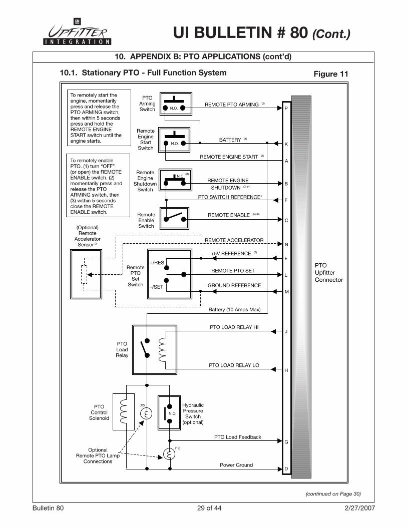
10.1. Stationary PTO - Full Function System Figure 11
53
N.O.
N.O.
N.C. (3)
N.O.
(12)
To remotely enablePTO. (1) turn off (oropen) the REMOTEENABLE switch. (2)momentarily press andrelease the PTOARMING switch, then(3) within 5 secondsclose the REMOTEENABLE switch.
PTOArmingSwitch
RemoteEnableSwitch
N.O.
Power Ground
PTOUpfitterConnector
Notes: 1. The BATTERY must be used, as shown, in this circuit. Remote engine start will not function if the switch is connected to IGNITION or +12V SWITCH REFERENCE. 2. The REMOTE PTO ARMING switch must be a momentary, normally open (N.O.) type. 3. The REMOTE PTO ENABLE switch must be a latching, single-pole/single-throw type. 4. The REMOTE PTO ENABLE switch must be connected, as shown, to the +12V SWITCH REFERENCE IGNITION.
REMOTE ENABLE (3)
G
D
H
J
M
L
E
N
C
F
B
A
K
P
To remotely start theengine, momentarilypress and release thePTO ARMING switch,then within 5 secondspress and hold theREMOTE ENGINESTART switch until theengine starts.
To remotely enablePTO. (1) turn “OFF”(or open) the REMOTEENABLE switch. (2)momentarily press andrelease the PTOARMING switch, then(3) within 5 secondsclose the REMOTEENABLE switch.
RemoteEngineStart
Switch
RemoteEngine
ShutdownSwitch
RemoteEnableSwitch(Optional)
RemoteAccelerator
Sensor (2)
RemotePTOSet
Switch
PTOLoadRelay
PTOControl
Solenoid
OptionalRemote PTO Lamp
Connections
(12)
+/RES
-/SET
HydraulicPressureSwitch
(optional)
PTO Load Feedback
PTO LOAD RELAY LO
PTO LOAD RELAY HI
Battery (10 Amps Max)
GROUND REFERENCE
REMOTE PTO SET
+5V REFERENCE (7)
REMOTE ACCELERATOR
REMOTE ENABLE (5) (6)
PTO SWITCH REFERENCE*
SHUTDOWN (3) (4)
REMOTE ENGINE
REMOTE ENGINE START (2)
BATTERY (1)
REMOTE PTO ARMING (2)

�0 of 44Bulletin 80 2/27/2007
UI BULLETIN # 80 (Cont.)
10. APPENDIX B: PTO APPLICATIONS (cont’d)
(continued on Page 31)
STATIONARY PTO – FULL FUNCTION SYSTEMRecommended PTO Programmable Settings
ProgrammableParameters
ProgrammableOptions
RecommendedSettings Notes
PTO Type(See section 7.� forinstruction on “PTO Type”programming – available inMY2009, BCM will no longer require programming)
STATIONARY PRESET–
STATIONARY VARIABLE–
MOBILE VARIABLE
STATIONARY PRESET
PTO In-Cab Control DISABLEDENABLED ENABLED
PTO Remote Control DISABLEDENABLED ENABLED
Type of Set SwitchOperation
MOMENTARYLATCHING N/A
Press “ON” then go to Preset � Speed
DISABLEDENABLED DISABLED
Remote Engine Start DISABLEDENABLED ENABLED
Remote Engine ShutdownDISABLEDENABLED ENABLED
Load feedbackDISABLEDENABLED ENABLED
Engage RelayDISABLEDENABLED ENABLED
Keep Relay engageduring braking
DISABLEDENABLED N/A
Action after brake isreleased
RETURN TO BASE IDLE RPM
–RETURN TO
STANDBY RPM
N/A
Auto Engine ShutdownTimer
DISABLEDENABLED ENABLED
Engine Shutdown due to Critical Engine Condition
DISABLEDENABLED ENABLED
Note: See beginning of Section 10 for engine speed parameters. The user can re-program these parameters to meet the specific requirements of the PTO application.
�� of 44Bulletin 80 2/27/2007
UI BULLETIN # 80 (Cont.)
10. APPENDIX B: PTO APPLICATIONS (cont’d)
(continued on Page 32)
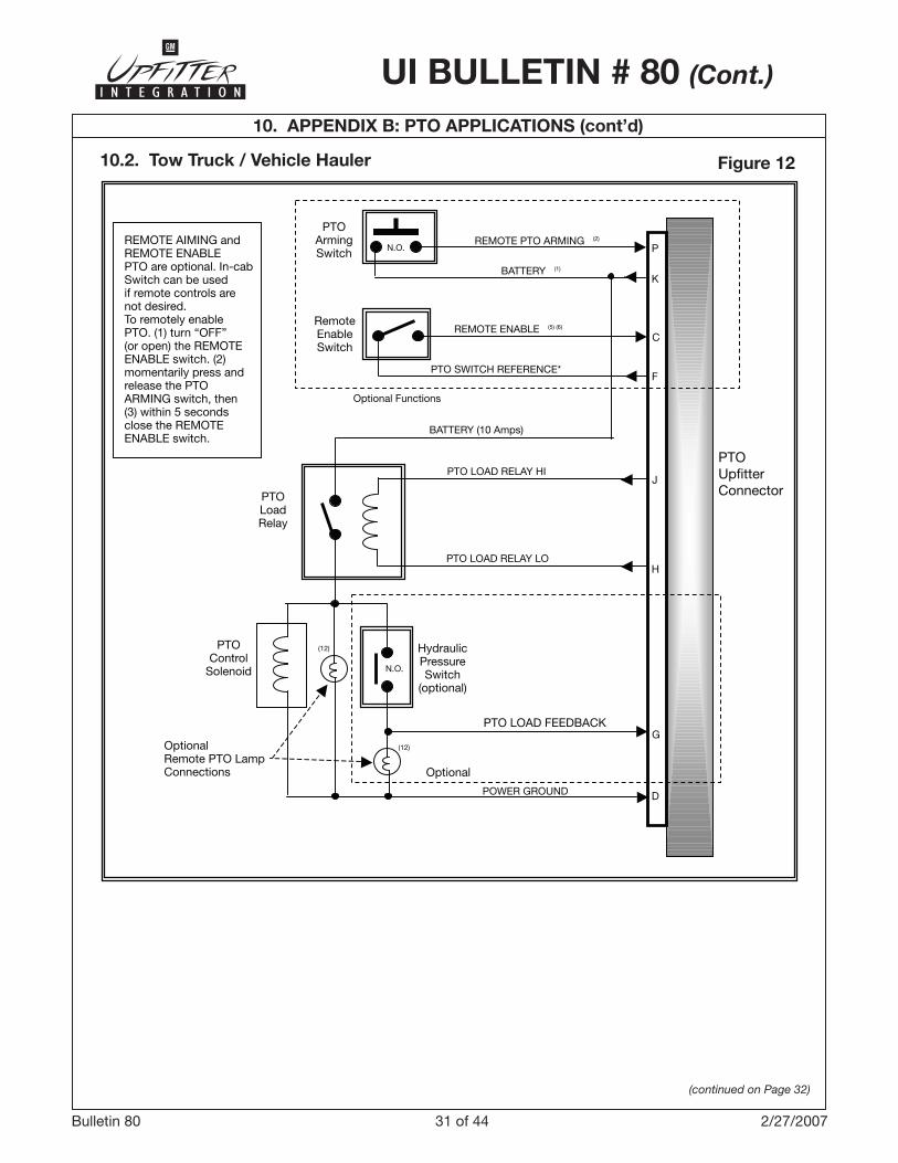
10.2. Tow Truck / Vehicle Hauler Figure 12
N.O.
N.O.
(12)
(12)
PTOUpfitterConnector
D
H
J
F
C
REMOTE AIMING andREMOTE ENABLEPTO are optional. In-cabSwitch can be usedif remote controls arenot desired.To remotely enablePTO. (1) turn “OFF”(or open) the REMOTEENABLE switch. (2)momentarily press andrelease the PTOARMING switch, then(3) within 5 secondsclose the REMOTEENABLE switch.
HydraulicPressureSwitch
(optional)
PTOControl
Solenoid
OptionalRemote PTO LampConnections
PTOLoadRelay
PTOArmingSwitch
RemoteEnableSwitch
PTO LOAD FEEDBACK
Optional
POWER GROUND
PTO LOAD RELAY LO
PTO LOAD RELAY HI
BATTERY (10 Amps)
Optional Functions
PTO SWITCH REFERENCE*
REMOTE ENABLE (5) (6)
BATTERY (1)
REMOTE PTO ARMING (2)
G
K
P

�2 of 44Bulletin 80 2/27/2007
UI BULLETIN # 80 (Cont.)
10. APPENDIX B: PTO APPLICATIONS (cont’d)
(continued on Page 33)
TOW TRUCK – VEHICLE HAULERRecommended PTO Programmable Settings
ProgrammableParameters
ProgrammableOptions
RecommendedSettings Notes
PTO Type(See section 7.� forinstruction on “PTO Type”programming – available inMY2009, BCM will no longer require programming)
STATIONARY PRESET–
STATIONARY VARIABLE–
MOBILE VARIABLE
STATIONARY PRESET
PTO In-Cab Control DISABLEDENABLED ENABLED
PTO Remote Control DISABLEDENABLED DISABLED
Type of Set SwitchOperation
MOMENTARYLATCHING N/A
Press “ON” then go to Preset � Speed
DISABLEDENABLED ENABLED
Remote Engine Start DISABLEDENABLED DISABLED
Remote Engine ShutdownDISABLEDENABLED DISABLED
Load feedbackDISABLEDENABLED ENABLED
Engage RelayDISABLEDENABLED ENABLED
Keep Relay engageduring braking
DISABLEDENABLED N/A
Action after brake isreleased
RETURN TO BASE IDLE RPM
–RETURN TO
STANDBY RPM
RETURN TO BASE IDLE
RPM
Auto Engine ShutdownTimer
DISABLEDENABLED DISABLED
Engine Shutdown due to Critical Engine Condition
DISABLEDENABLED DISABLED
Engine Shutdown warning DISABLEDENABLED DISABLED
Note: See beginning of Section 10 for engine speed parameters. The user can re-program these parameters to meet the specific requirements of the PTO application.

�� of 44Bulletin 80 2/27/2007
UI BULLETIN # 80 (Cont.)
10. APPENDIX B: PTO APPLICATIONS (cont’d)
(continued on Page 34)
10.3. Lift Bucket / Lift Gate Figure 13
N.O.
N.O.
N.C. (3)
N.O.
(12)
(12)
To remotely start theengine, momentarilypress and release thePTO ARMING switch,then within 5 secondspress and hold theREMOTE ENGINESTART switch until theengine starts.
HydraulicPressureSwitch
(optional)
PTOControl
Solenoid
OptionalRemote PTO LampConnections
PTOLoadRelay
PTOUpfitterConnector
PTOArmingSwitch
RemoteEngineStart
Switch
BATTERY (1)
REMOTE PTO ARMING
To remotely enablePTO. (1) turn “OFF”(or open) the REMOTEENABLE switch. (2)momentarily press andrelease the PTOARMING switch, then(3) within 5 secondsclose the REMOTEENABLE switch.
RemoteEngineShutdownSwitch
RemoteEnableSwitch
REMOTE ENGINE START
REMOTE ENGINE SHUTDOWN
PTO SWITCH REFERENCE (2)
REMOTE ENABLE (5) (6)
BATTERY (10 Amps)
PTO LOAD RELAY HI
PTO LOAD RELAY LO
PTO LOAD FEEDBACK
POWER GROUNDD
H
J
F
C
G
K
A
B
P
Notes: 1. The REMOTE PTO ARMING and REMOTE ENGINE START switches must be connected to BATTERY to work properly (the IGNITION and the PTO SWITCH REFERENCE wires cannot be used). 2. The REMOTE ENGINE SHUTDOWN and REMOTE PTO ENABLE switch must be connected to either IGNITION or the PTO SWITCH REFERENCE wire. Connecting these switches to the BATTERY could cause battery run-down.

�4 of 44Bulletin 80 2/27/2007
UI BULLETIN # 80 (Cont.)
10. APPENDIX B: PTO APPLICATIONS (cont’d)
(continued on Page 35)
LIFT BUCKET – LIFT GATERecommended PTO Programmable Settings
ProgrammableParameters
ProgrammableOptions
RecommendedSettings Notes
PTO Type(See section 7.� forinstruction on “PTO Type”programming – available inMY2009, BCM will no longer require programming)
STATIONARY PRESET–
STATIONARY VARIABLE–
MOBILE VARIABLE
STATIONARY PRESET
PTO In-Cab Control DISABLEDENABLED ENABLED
PTO Remote Control DISABLEDENABLED ENABLED
Type of Set SwitchOperation
MOMENTARYLATCHING MOMENTARY
Press “ON” then go to Preset � Speed
DISABLEDENABLED ENABLED
Remote Engine Start DISABLEDENABLED ENABLED
Remote Engine ShutdownDISABLEDENABLED ENABLED
Load feedbackDISABLEDENABLED ENABLED
Engage RelayDISABLEDENABLED ENABLED
Keep Relay engageduring braking
DISABLEDENABLED N/A
Action after brake isreleased
RETURN TO BASE IDLE RPM
–RETURN TO
STANDBY RPM
RETURN TO BASE IDLE
RPM
Auto Engine ShutdownTimer
DISABLEDENABLED ENABLED
Engine Shutdown due to Critical Engine Condition
DISABLEDENABLED ENABLED
Engine Shutdown warning DISABLEDENABLED ENABLED
Note: See beginning of Section 10 for engine speed parameters. The user can re-program these parameters to meet the specific requirements of the PTO application.

�5 of 44Bulletin 80 2/27/2007
UI BULLETIN # 80 (Cont.)
10. APPENDIX B: PTO APPLICATIONS (cont’d)
(continued on Page 36)
10.4. Water Pumping Operation / Electric Generator / Lift Gate Figure 14
24
N.O.
N.O.
To remotely enablePTO. (1) turn “OFF”(or open) the REMOTEENABLE switch. (2)momentarily press andrelease the PTOARMING switch, then(3) within 5 secondsclose the REMOTEENABLE switch.
HydraulicPressureSwitch
(optional)
PTOControl
Solenoid
OptionalRemote PTO LampConnections
PTOLoadRelay
PTOUpfitterConnector
RemotePTOArmingSwitch(optional)
REMOTE PTO ARMING
(Optional)Remote
AcceleratorSensor (1)
RemoteEnableSwitch
PTO SWITCH REFERENCE (2)
REMOTE ENABLE
D
H
J
N
E
G
F
C
P
Notes: 1. Select either the accelerator or Remote Set Switch if engine speed will need to be varied by application.
2. REMOTE PTO ARMING can be connected to IGNITION or PTO SWITCH REFERENCE when the vehicle will not be started remotely.
RemotePTOSet
Switch (1)
(optional)
+/RES
-/SET
K
L
M
REMOTE ACCELERATOR
+5V REFERENCE
REMOTE PTO SET
GROUND REFERENCE
Battery (10 Amps Max)
PTO LOAD RELAY HI
PTO LOAD RELAY LO
PTO LOAD FEEDBACK
POWER GROUND
�6 of 44Bulletin 80 2/27/2007
UI BULLETIN # 80 (Cont.)
10. APPENDIX B: PTO APPLICATIONS (cont’d)
(continued on Page 37)
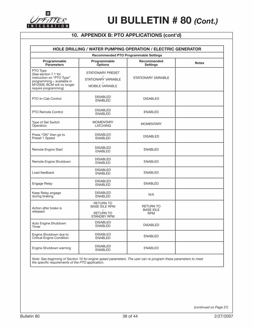
HOLE DRILLING / WATER PUMPING OPERATION / ELECTRIC GENERATORRecommended PTO Programmable Settings
ProgrammableParameters
ProgrammableOptions
RecommendedSettings Notes
PTO Type(See section 7.� forinstruction on “PTO Type”programming – available inMY2009, BCM will no longer require programming)
STATIONARY PRESET–
STATIONARY VARIABLE–
MOBILE VARIABLE
STATIONARY VARIABLE
PTO In-Cab Control DISABLEDENABLED DISABLED
PTO Remote Control DISABLEDENABLED ENABLED
Type of Set SwitchOperation
MOMENTARYLATCHING MOMENTARY
Press “ON” then go to Preset � Speed
DISABLEDENABLED DISABLED
Remote Engine Start DISABLEDENABLED ENABLED
Remote Engine ShutdownDISABLEDENABLED ENABLED
Load feedbackDISABLEDENABLED ENABLED
Engage RelayDISABLEDENABLED ENABLED
Keep Relay engageduring braking
DISABLEDENABLED N/A
Action after brake isreleased
RETURN TO BASE IDLE RPM
–RETURN TO
STANDBY RPM
RETURN TO BASE IDLE
RPM
Auto Engine ShutdownTimer
DISABLEDENABLED DISABLED
Engine Shutdown due to Critical Engine Condition
DISABLEDENABLED ENABLED
Engine Shutdown warning DISABLEDENABLED ENABLED
Note: See beginning of Section 10 for engine speed parameters. The user can re-program these parameters to meet the specific requirements of the PTO application.
�7 of 44Bulletin 80 2/27/2007
UI BULLETIN # 80 (Cont.)
10. APPENDIX B: PTO APPLICATIONS (cont’d)
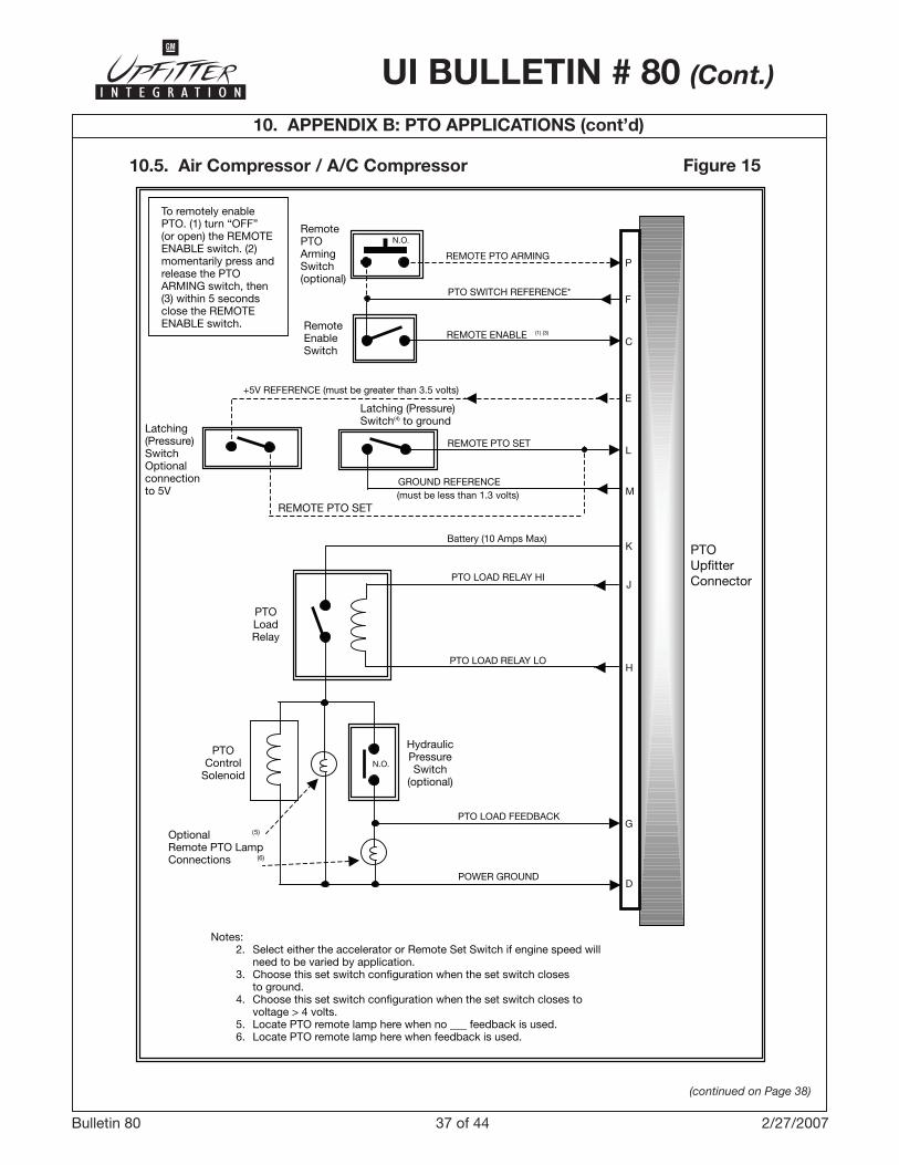
10.5. Air Compressor / A/C Compressor Figure 15
(continued on Page 38)
44
N.O.
(5)
(6)
N.O.
To remotely enablePTO. (1) turn “OFF”(or open) the REMOTEENABLE switch. (2)momentarily press andrelease the PTOARMING switch, then(3) within 5 secondsclose the REMOTEENABLE switch.
HydraulicPressureSwitch
(optional)
PTOControl
Solenoid
OptionalRemote PTO LampConnections
PTOLoadRelay
PTOUpfitterConnector
RemotePTOArmingSwitch(optional)
REMOTE PTO ARMING
RemoteEnableSwitch
PTO SWITCH REFERENCE*
REMOTE ENABLE (1) (3)
PTO LOAD RELAY HI
PTO LOAD RELAY LO
PTO LOAD FEEDBACK
POWER GROUND
Notes: 2. Select either the accelerator or Remote Set Switch if engine speed will need to be varied by application. 3. Choose this set switch configuration when the set switch closes to ground. 4. Choose this set switch configuration when the set switch closes to voltage > 4 volts. 5. Locate PTO remote lamp here when no ___ feedback is used. 6. Locate PTO remote lamp here when feedback is used.
D
G
J
H
L
M
K
P
Latching(Pressure)SwitchOptionalconnectionto 5V
Latching (Pressure)Switch(4) to ground
REMOTE PTO SET
F
C
E
REMOTE PTO SET
Battery (10 Amps Max)
+5V REFERENCE (must be greater than 3.5 volts)
GROUND REFERENCE(must be less than 1.3 volts)

�8 of 44Bulletin 80 2/27/2007
UI BULLETIN # 80 (Cont.)
10. APPENDIX B: PTO APPLICATIONS (cont’d)
(continued on Page 39)
AIR COMPRESSOR / A/C COMPRESSORRecommended PTO Programmable Settings
ProgrammableParameters
ProgrammableOptions
RecommendedSettings Notes
PTO Type(See section 7.� forinstruction on “PTO Type”programming – available inMY2009, BCM will no longer require programming)
STATIONARY PRESET–
STATIONARY VARIABLE–
MOBILE VARIABLE
STATIONARY PRESET
PTO In-Cab Control DISABLEDENABLED DISABLED
PTO Remote Control DISABLEDENABLED ENABLED
Type of Set SwitchOperation
MOMENTARYLATCHING LATCHING
Press “ON” then go to Preset � Speed
DISABLEDENABLED DISABLED
Remote Engine Start DISABLEDENABLED DISABLED
Remote Engine ShutdownDISABLEDENABLED DISABLED
Load feedbackDISABLEDENABLED ENABLED
Engage RelayDISABLEDENABLED ENABLED
Keep Relay engageduring braking
DISABLEDENABLED N/A
Action after brake isreleased
RETURN TO BASE IDLE RPM
–RETURN TO
STANDBY RPM
RETURN TO BASE IDLE
RPM
Auto Engine ShutdownTimer
DISABLEDENABLED DISABLED
Engine Shutdown due to Critical Engine Condition
DISABLEDENABLED ENABLED
Engine Shutdown warning DISABLEDENABLED ENABLED
Note: See beginning of Section 10 for engine speed parameters. The user can re-program these parameters to meet the specific requirements of the PTO application.
�9 of 44Bulletin 80 2/27/2007
UI BULLETIN # 80 (Cont.)
10. APPENDIX B: PTO APPLICATIONS (cont’d)
(continued on Page 40)
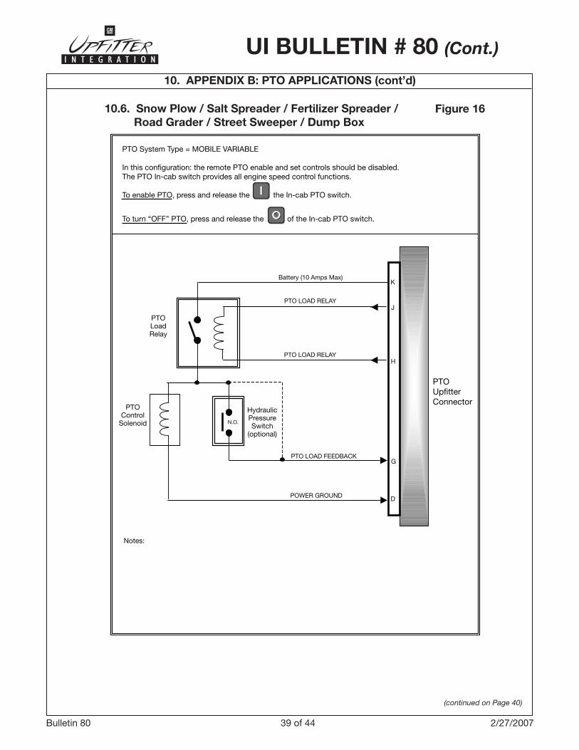
10.6. Snow Plow / Salt Spreader / Fertilizer Spreader / Road Grader / Street Sweeper / Dump Box
Figure 16
N.O.
HydraulicPressureSwitch
(optional)
PTOControl
Solenoid
PTOLoadRelay
PTOUpfitterConnector
PTO LOAD RELAY
PTO LOAD FEEDBACK
POWER GROUND
J
D
G
K
H
Battery (10 Amps Max)
Notes:
PTO LOAD RELAY
PTO System Type = MOBILE VARIABLE
In this configuration: the remote PTO enable and set controls should be disabled.The PTO In-cab switch provides all engine speed control functions.
To enable PTO, press and release the the In-cab PTO switch.
To turn “OFF” PTO, press and release the of the In-cab PTO switch.
40 of 44Bulletin 80 2/27/2007
UI BULLETIN # 80 (Cont.)
10. APPENDIX B: PTO APPLICATIONS (cont’d)
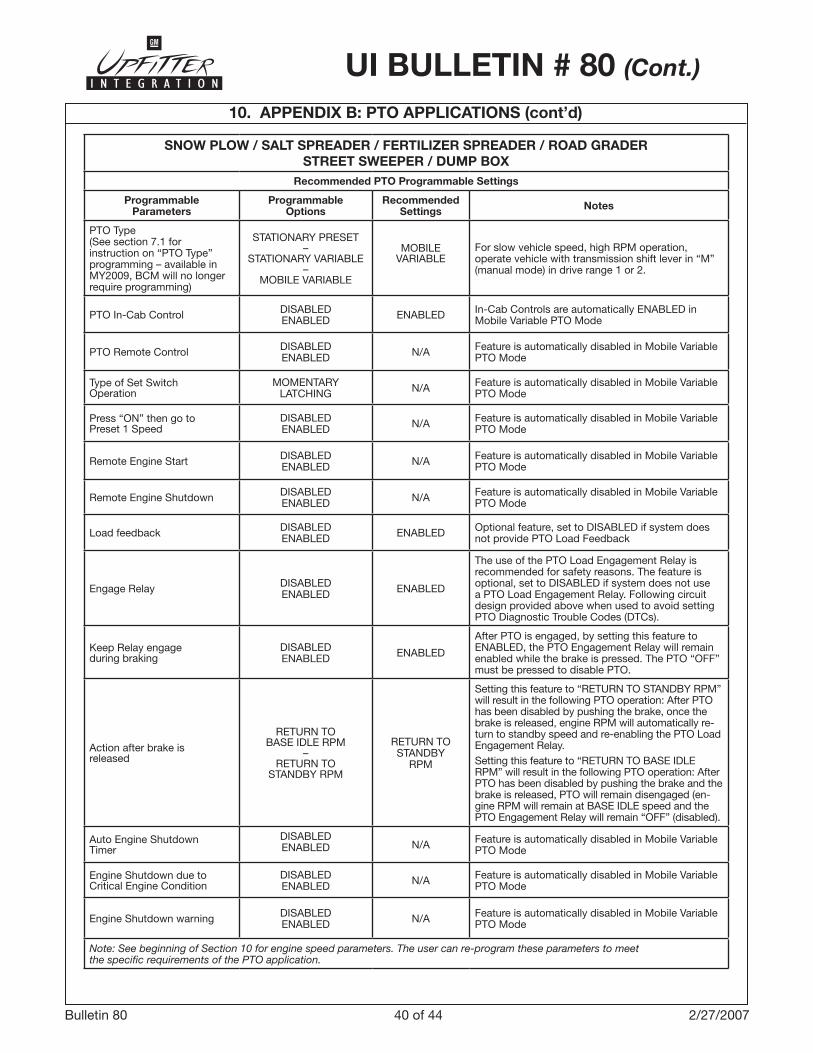
SNOW PLOW / SALT SPREADER / FERTILIZER SPREADER / ROAD GRADERSTREET SWEEPER / DUMP BOX
Recommended PTO Programmable Settings
ProgrammableParameters
ProgrammableOptions
RecommendedSettings Notes
PTO Type(See section 7.� forinstruction on “PTO Type”programming – available inMY2009, BCM will no longer require programming)
STATIONARY PRESET–
STATIONARY VARIABLE–
MOBILE VARIABLE
MOBILE VARIABLE
For slow vehicle speed, high RPM operation, operate vehicle with transmission shift lever in “M” (manual mode) in drive range � or 2.
PTO In-Cab Control DISABLEDENABLED ENABLED In-Cab Controls are automatically ENABLED in
Mobile Variable PTO Mode
PTO Remote Control DISABLEDENABLED N/A Feature is automatically disabled in Mobile Variable
PTO Mode
Type of Set SwitchOperation
MOMENTARYLATCHING N/A Feature is automatically disabled in Mobile Variable
PTO Mode
Press “ON” then go to Preset � Speed
DISABLEDENABLED N/A Feature is automatically disabled in Mobile Variable
PTO Mode
Remote Engine Start DISABLEDENABLED N/A Feature is automatically disabled in Mobile Variable
PTO Mode
Remote Engine Shutdown DISABLEDENABLED N/A Feature is automatically disabled in Mobile Variable
PTO Mode
Load feedback DISABLEDENABLED ENABLED Optional feature, set to DISABLED if system does
not provide PTO Load Feedback
Engage Relay DISABLEDENABLED ENABLED
The use of the PTO Load Engagement Relay is recommended for safety reasons. The feature is optional, set to DISABLED if system does not use a PTO Load Engagement Relay. Following circuit design provided above when used to avoid setting PTO Diagnostic Trouble Codes (DTCs).
Keep Relay engageduring braking
DISABLEDENABLED ENABLED
After PTO is engaged, by setting this feature to ENABLED, the PTO Engagement Relay will remain enabled while the brake is pressed. The PTO “OFF” must be pressed to disable PTO.
Action after brake isreleased
RETURN TO BASE IDLE RPM
–RETURN TO
STANDBY RPM
RETURN TO STANDBY
RPM
Setting this feature to “RETURN TO STANDBY RPM” will result in the following PTO operation: After PTO has been disabled by pushing the brake, once the brake is released, engine RPM will automatically re-turn to standby speed and re-enabling the PTO Load Engagement Relay.Setting this feature to “RETURN TO BASE IDLE RPM” will result in the following PTO operation: After PTO has been disabled by pushing the brake and the brake is released, PTO will remain disengaged (en-gine RPM will remain at BASE IDLE speed and the PTO Engagement Relay will remain “OFF” (disabled).
Auto Engine ShutdownTimer
DISABLEDENABLED N/A Feature is automatically disabled in Mobile Variable
PTO Mode
Engine Shutdown due to Critical Engine Condition
DISABLEDENABLED N/A Feature is automatically disabled in Mobile Variable
PTO Mode
Engine Shutdown warning DISABLEDENABLED N/A Feature is automatically disabled in Mobile Variable
PTO Mode
Note: See beginning of Section 10 for engine speed parameters. The user can re-program these parameters to meet the specific requirements of the PTO application.
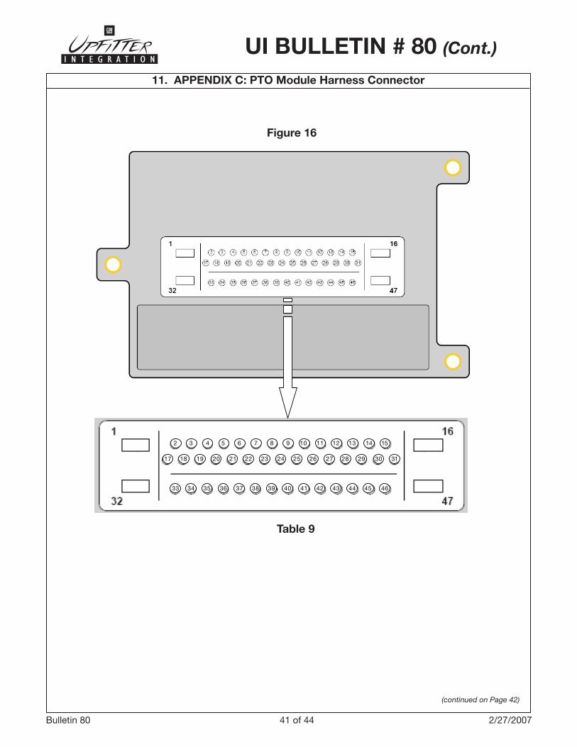
4� of 44Bulletin 80 2/27/2007
UI BULLETIN # 80 (Cont.)
11. APPENDIX C: PTO Module Harness Connector
Figure 16
(continued on Page 42)
2 3 4 5 6 7 8 9 10 11 12 13 14 15
33 34 35 36 37 38 39 40 41 42 43 44 45 46
3118 19 20 21 22 23 24 25 26 27 28 29 3017
Table 9
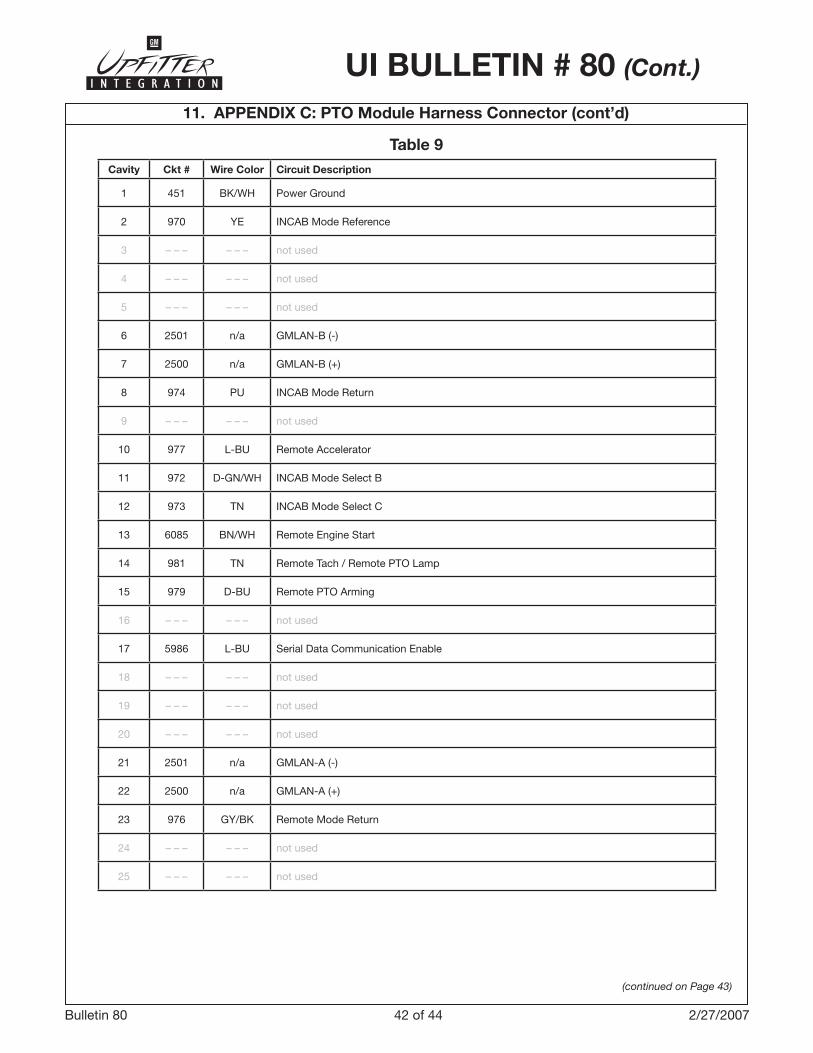
42 of 44Bulletin 80 2/27/2007
UI BULLETIN # 80 (Cont.)
11. APPENDIX C: PTO Module Harness Connector (cont’d)
Table 9
(continued on Page 43)
Cavity Ckt # Wire Color Circuit Description
� 45� BK/WH Power Ground
2 970 YE INCAB Mode Reference
� – – – – – – not used
4 – – – – – – not used
5 – – – – – – not used
6 250� n/a GMLAN-B (-)
7 2500 n/a GMLAN-B (+)
8 974 PU INCAB Mode Return
9 – – – – – – not used
�0 977 L-BU Remote Accelerator
�� 972 D-GN/WH INCAB Mode Select B
�2 97� TN INCAB Mode Select C
�� 6085 BN/WH Remote Engine Start
�4 98� TN Remote Tach / Remote PTO Lamp
�5 979 D-BU Remote PTO Arming
�6 – – – – – – not used
�7 5986 L-BU Serial Data Communication Enable
�8 – – – – – – not used
�9 – – – – – – not used
20 – – – – – – not used
2� 250� n/a GMLAN-A (-)
22 2500 n/a GMLAN-A (+)
2� 976 GY/BK Remote Mode Return
24 – – – – – – not used
25 – – – – – – not used
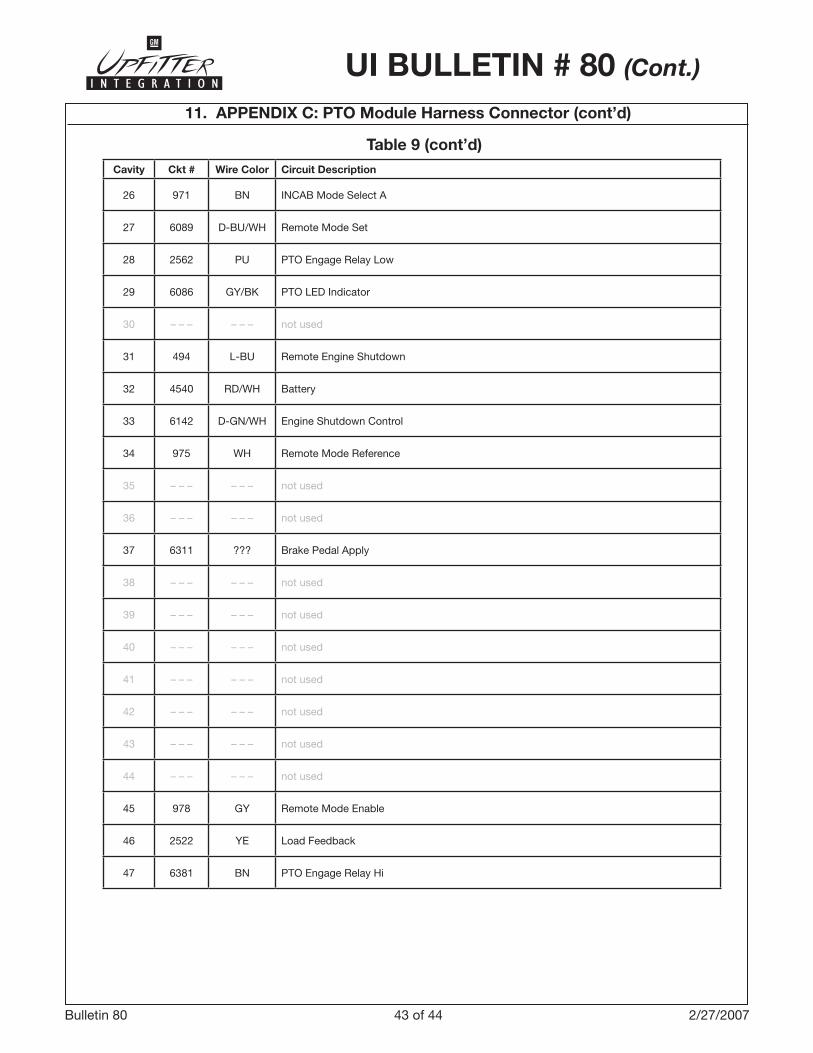
4� of 44Bulletin 80 2/27/2007
UI BULLETIN # 80 (Cont.)
11. APPENDIX C: PTO Module Harness Connector (cont’d)
Table 9 (cont’d)Cavity Ckt # Wire Color Circuit Description
26 97� BN INCAB Mode Select A
27 6089 D-BU/WH Remote Mode Set
28 2562 PU PTO Engage Relay Low
29 6086 GY/BK PTO LED Indicator
�0 – – – – – – not used
�� 494 L-BU Remote Engine Shutdown
�2 4540 RD/WH Battery
�� 6�42 D-GN/WH Engine Shutdown Control
�4 975 WH Remote Mode Reference
�5 – – – – – – not used
�6 – – – – – – not used
�7 6��� ??? Brake Pedal Apply
�8 – – – – – – not used
�9 – – – – – – not used
40 – – – – – – not used
4� – – – – – – not used
42 – – – – – – not used
4� – – – – – – not used
44 – – – – – – not used
45 978 GY Remote Mode Enable
46 2522 YE Load Feedback
47 6�8� BN PTO Engage Relay Hi
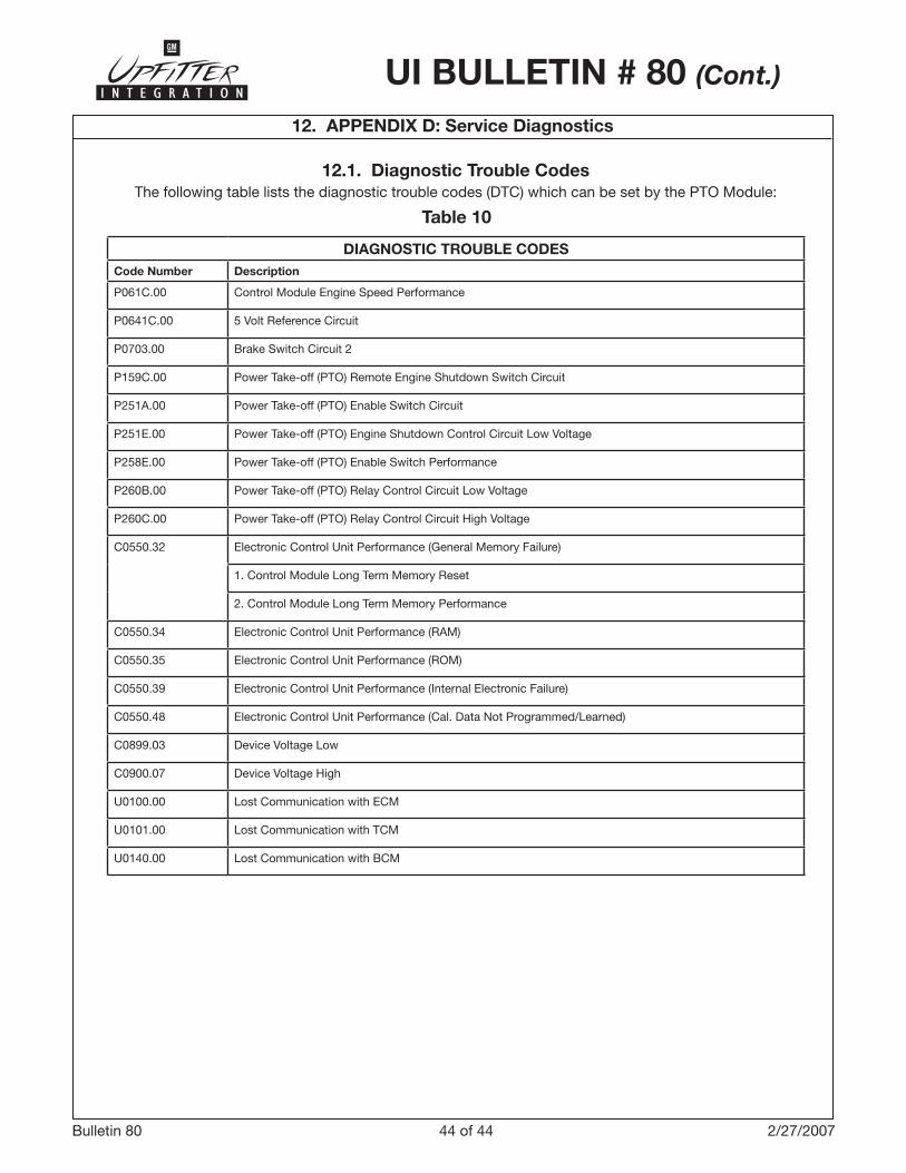
44 of 44Bulletin 80 2/27/2007
12. APPENDIX D: Service Diagnostics
Table 10
12.1. Diagnostic Trouble CodesThe following table lists the diagnostic trouble codes (DTC) which can be set by the PTO Module:
DIAGNOSTIC TROUBLE CODESCode Number Description
P06�C.00 Control Module Engine Speed Performance
P064�C.00 5 Volt Reference Circuit
P070�.00 Brake Switch Circuit 2
P�59C.00 Power Take-off (PTO) Remote Engine Shutdown Switch Circuit
P25�A.00 Power Take-off (PTO) Enable Switch Circuit
P25�E.00 Power Take-off (PTO) Engine Shutdown Control Circuit Low Voltage
P258E.00 Power Take-off (PTO) Enable Switch Performance
P260B.00 Power Take-off (PTO) Relay Control Circuit Low Voltage
P260C.00 Power Take-off (PTO) Relay Control Circuit High Voltage
C0550.�2 Electronic Control Unit Performance (General Memory Failure)
�. Control Module Long Term Memory Reset
2. Control Module Long Term Memory Performance
C0550.�4 Electronic Control Unit Performance (RAM)
C0550.�5 Electronic Control Unit Performance (ROM)
C0550.�9 Electronic Control Unit Performance (Internal Electronic Failure)
C0550.48 Electronic Control Unit Performance (Cal. Data Not Programmed/Learned)
C0899.0� Device Voltage Low
C0900.07 Device Voltage High
U0�00.00 Lost Communication with ECM
U0�0�.00 Lost Communication with TCM
U0�40.00 Lost Communication with BCM
UI BULLETIN # 80 (Cont.)