Embed Size (px)
Citation preview
2021 UPFITTER SCHEMATIC3500/4500/5500CHASSIS CABS
AK H
BC
GL
F
DJ
E
A Aux PDC (auxiliary Power Distribution Center-relay/fuse box)
Underhood
B
C
D
E
F
J
G
H
2 Upfitter Connectors (Light and Dark Gray)
PDC (main Power Distribution Center-relay/fuse box) underhood
Port Upfitters Connectors, Under
Dash Board near park brake bracket / Steering Column
PTO Connector Wires located underneath vehicle at Transmission Bell
Housing, Left (Driver) Side
Park sense connector
Vehicle Wiring, Blunt Cut (with Heat Shrink) Rear of Frame
Blunt Cut (with Heat Shrink) wires underneath the PDC
VSIM Module located interior of vehicle under dash
Aux 6/PTO jumper connector, alongside left (Drivers Side) fender inner
Rear Camera Connector
Max Combined Fuse "rating" allowed for Aux SW 1, 2, 3, 4, 5, 6/PTO,Run Only & Battery is 210A. Fuses can be relocated in box as necessary.Max allowable combined total continuous amperage draw is 135A.Max fuse "rating" in any one location is 40A, except the Run Only Feed fuse allowed only to 20A.
*The upfitter/customer is responsible for placing the correctfuse in the correct location depending on the actual load.
*Amperages shown in schematics are for fuses/circuits as installed forthe vehicle as sold and will change as fuses are reconfigured.
MAX ALLOWABLECONTINUOUS AMPERAGEDRAW PER FUSE RATING
The auxiliary switch function logic (BATTERY orIGNITION FED, MOMENTARY or LATCHING,LAST STATE) is programmed using the EVICdisplay in the instrument cluster.
FUSE RATING
MAXALLOWABLE
CONTINUOUSAMPERAGE
20A
25A
40A
14A
17.5A
28A
K
L
A
Ground Point (50A Total Max Load)
GND (Frame Rail)
Page : 1/18
Rev. Date: 01/28/2021
Dash Pass ThruU
U
UPFITTER PASS THROUGH WIRES
Trailer Tow Lighting
Pass- through Circuits
W751,W752,W753, W756
W750, W754,W755
W547,W548, W549, W550
MAXALLOWABLE
CONTINUOUSAMPERAGE
14A
21A
28A
Trailer Tow Battery, Brake Ground

2021 UPFITTER SCHEMATIC2500/3500PICKUP BOX DELETE (XBC)With AUX switches (LHL)
A
M
HB
C
GLF
D J
A Aux PDC (auxiliary Power Distribution Center-relay/fuse box)
Underhood
B
C
D
J
G
H
2 Upfitter Connectors (Light and Dark Gray)
PDC (main Power Distribution Center-relay/fuse box) underhood
Port Upfitters Connectors, Under
Dash Board near park brake bracket / Steering Column
Vehicle Wiring, Blunt Cut (with Heat Shrink) Rear of Frame
Blunt Cut (with Heat Shrink) wires underneath the PDC
VSIM Module located interior of vehicle under dash if equipped (sales code XXS)
Blunt Cut (with Heat Shrink) Stop Lamp Signal – CHMSL Feed
Rear Camera Connector
Max Combined Fuse "rating" allowed for Aux SW 1, 2, 3, 4, 5, 6,Run Only & Battery is 210A. Fuses can be relocated in box as necessary.Max allowable combined total continuous amperage draw is 135A.Max fuse "rating" in any one location is 40A, except the Run Only Feed fuse allowed only to 20A.
*The upfitter/customer is responsible for placing the correctfuse in the correct location depending on the actual load.
*Amperages shown in schematics are for fuses/circuits as installed forthe vehicle as sold and will change as fuses are reconfigured.The auxiliary switch function logic (BATTERY or
IGNITION FED, MOMENTARY or LATCHING,LAST STATE) is programmed using the EVICdisplay in the instrument cluster.
FUSE RATING
MAXALLOWABLE
CONTINUOUSAMPERAGE
20A
25A
40A
14A
17.5A
28A
M
F
L
A
Ground Point (50A Total Max Load)
GND (Frame Rail)
MAX ALLOWABLECONTINUOUS AMPERAGEDRAW PER FUSE RATING
Page : 2/18
Dash Pass ThruU
U
UPFITTER PASS THROUGH WIRES
Trailer Tow Lighting
Pass- through Circuits
W751,W752,W753, W756
W750, W754,W755
W547,W548, W549, W550
MAXALLOWABLE
CONTINUOUSAMPERAGE
14A
21A
28A
Trailer Tow Battery, Brake Ground

2021 UPFITTER SCHEMATIC2500/3500PICKUP BOX ONWith AUX switches (LHL)
A
M
H
B
C
FD J
A Aux PDC (auxiliary Power Distribution Center-relay/fuse box)
Underhood
B
C
D
J
H
2 Upfitter Connectors (Light and Dark Gray)
PDC (main Power Distribution Center-relay/fuse box) underhood
Port Upfitters Connectors, Under
Dash Board near park brake bracket / Steering Column
Vehicle Wiring, Blunt Cut (with Heat Shrink) Rear of Frame
Blunt Cut (with Heat Shrink) wires underneath the PDC
VSIM Module located interior of vehicle under dash if equipped (sales code XXS)
Blunt Cut (with Heat Shrink) Stop Lamp Signal – CHMSL
Feed
Max Combined Fuse "rating" allowed for Aux SW 1, 2, 3, 4, 5, 6,Run Only & Battery is 210A. Fuses can be relocated in box as necessary.Max allowable combined total continuous amperage draw is 135A.Max fuse "rating" in any one location is 40A, except the Run Only Feed fuse allowed only to 20A.
*The upfitter/customer is responsible for placing the correctfuse in the correct location depending on the actual load.
*Amperages shown in schematics are for fuses/circuits as installed forthe vehicle as sold and will change as fuses are reconfigured.The auxiliary switch function logic (BATTERY or
IGNITION FED, MOMENTARY or LATCHING,LAST STATE) is programmed using the EVICdisplay in the instrument cluster.
FUSE RATING
MAXALLOWABLE
CONTINUOUSAMPERAGE
20A
25A
40A
14A
17.5A
28A
M
F
A
Ground Point (50A Total Max Load)
GND (Frame Rail)
MAX ALLOWABLECONTINUOUS AMPERAGEDRAW PER FUSE RATING
Page : 3/18
Dash Pass ThruU
U
UPFITTER PASS THROUGH WIRES
Trailer Tow Lighting
Pass- through Circuits
W751,W752,W753, W756
W750, W754,W755
W547,W548, W549, W550
MAXALLOWABLE
CONTINUOUSAMPERAGE
14A
21A
28A
Trailer Tow Battery, Brake Ground

2021 UPFITTER SCHEMATIC2500/3500PICKUPWithout AUX switches (LHL)
M
H C J
C
J
H
PDC (main Power Distribution Center-relay/fuse box) underhood
Blunt Cut (with Heat Shrink) wires underneath the PDC
MGround Point (50A Total Max Load)
GND (Frame Rail) VSIM Module located interior of vehicle under dash if equipped(sales code XXS)
Blunt Cut (with Heat Shrink) Stop Lamp Signal – CHMSL
Feed
Page : 4/18

2021 UPFITTER SCHEMATIC 3500/4500/5500 CHASIS CAB6.7 Diesel AISIN Trans w/PTO(Sales codes LBN/LBV)
ASSY PDC D6630E
(Dash LT w/h)
ASSY PDC D6630F
(Dash LT w/h)
MOD TCMD3855A
Y M P
31 34 25
A998 0.35 RD F940 0.35 PK/YE K427 0.5 OG/GN
Mod_ECMD3838AD3838B
B 8
Upfitter Aux PDC Box
D2620A_Upfitters
E
Cap & Plugs(Terminated wires
supplied in Upfitter Kit) B 32
B 67
B 63
K400 0.35 BN/VT K400 0.5 BN/VT
F856 0.5 YE/PKF856 0.5 YE/PK
B 93
B 94
B 57
K128 0.5 DB/GN
K129 0.5 DB/DG
K810 0.5 VT/DG
SK400A
SF856B
B 66K119 0.5 GN/BK
F425 0.5 PKF425 0.5 PK
V937 0.5 VT/BN
SF425A
SV937A
1
2
3
4
5
6
7
8
1
8B 90K425 0.5 OG/BN
F425 0.5 PK
V937 0.5 VT/BN
13
Y/X 105A
SK425 0.5 OG/BN
2
3
6
V937 0.5 VT/BN
F425 0.5 PK
WHITE Port_Upfitters_1
D2433AD
Jumper (Supplied in Upfitter Kit)
G905A
Z905 0.75 BK
V937 0.5 VT/BN
Z905 0.75 BK
Aux 1
A
Y
Aux 2
Aux 3
Aux 4
Aux 5
PTO
Run Only
Cap & Plugs(Terminated wires
supplied in Upfitter Kit)
B
1
2
4
3
F601 5.0 PK/DB
F602 5.0 PK/DG
F603 5.0 PK/VT
F604 5.0 PK/BG
B
1
2
4
3
Cap & Plugs(Terminated wires
supplied in Upfitter Kit)
Dark GrayConnector_Upfitter_Aux_1
D2622A_Aux_1_Das
Light GrayConnector_Upfitter_Aux_2
D2623A_Aux_2_DasF605 5.0 PK/BN
A998 0.35 RD
A998 0.35 RD
A998 0.35 RD
A998 0.35 RD
A998 0.35 RD
A998 0.35 RD
68
67
70
66
32
31
34
30
27
26
29
25
63
62
65
61
58
57
60
56
53
52
55
51
48
47
50
46
SA998A
F607 5.0 PK/YE
Z
Z907 3.0 BK
M F940 0.35 PK/YE
40A
44A962 3.0 RD
40A
43
25A
41
25A
42
20A
39
20A
37
20A
36
20A
45
A963 3.0 RD
A965 3.0 RD
A966 3.0 RD
A968 3.0 RD
A967 3.0 RD
A964 3.0 RD
G907A
Z907 0.35 BK
Z
B+
37
38
40
36
41
P821 0.35 BN/VT
P822 0.35 BN/WH
P823 0.35 BN/GY
P819 0.35 BG/BN
Aux SwitchBankUpper
D2321A
3
2
11
10
12
13
124 3
P
S K425 0.35 OG/BN
K427 0.5 OG/GN
P831 0.35 BN/YE P831 0.35 BN/YE
K427 0.5 OG/GN
K425 0.35 OG/BN
B+ LIN BUSA938 0.75 RD
D401 0.35 OG8
6
7G911A
I9001X/Y INLINE_I9001PTO JUMPER
DPort_Upfitters_2D2621A_Body_D
LIGHT GRAY
Y/X 960
A500 4.0 RD/WH
Y/X 920A
Y/X 910A
1
4
3
6
5
F606 1.0 PK/OG
A500 4.0 RD/WH
A500 4.0 RD/WH
F606 4.0 PK/OG
G425 4.0 VT/YE
A500 3.0 RD/WH
X/Y 125A
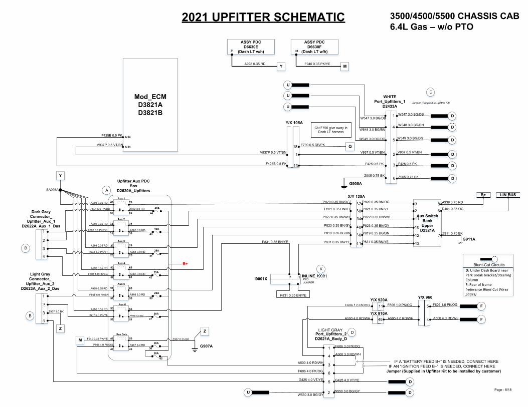
Blunt-Cut CircuitsD: Under Dash Board near Park Break bracket/Steering ColumnF: Rear of frame(reference Blunt Cut Wires pages)
F606 4.0 PK/OG
11
48
5
4
F606 3.0 PK/OG
IF A “BATTERY FEED B+” IS NEEDED, CONNECT HERE IF AN “IGNITION FEED B+” IS NEEDED, CONNECT HEREJumper (Supplied in Upfitter Kit to be installed by customer)
G425 4.0 VT/YE
F
F
F606 1.0 PK/OGF606 1.0 PK/OG
A500 4.0 RD/WH
Z911 0.75 BK
P820 0.35 BN/OG
P821 0.35 BN/VT
P822 0.35 BN/WH
P823 0.35 BN/GY
P819 0.35 BG/BN
P831 0.35 BN/YE
34
P820 0.35 BN/OG
D
D
D
F425 0.5 PK
V937 0.35 VT/BN
D
Connector_Upfitter_3_PTO_Trans
D2624A
Page : 5/18
2 W550 3.0 BG/GY DW550 3.0 BG/GYU
W547 3.0 BG/DB
W549 3.0 BG/DG
D
D
D
W548 3.0 BG/BN
1
4
5
W547 3.0 BG/DB
U
W548 3.0 BG/BN
U
W549 3.0 BG/DG
U
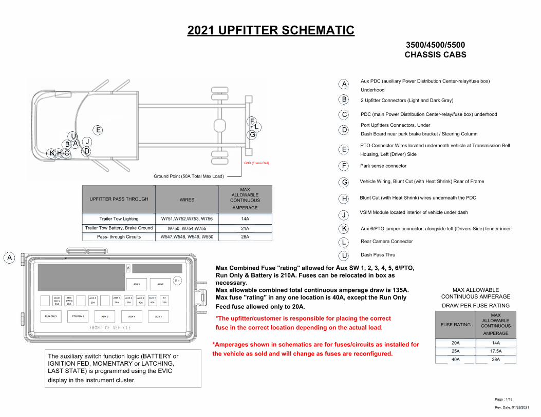
2021 UPFITTER SCHEMATIC3500/4500/5500 CHASSIS CAB6.4 Gas Asin Transw/PTO (Sales codes LBN/LBV)
ASSY PDC D6630E
(Dash LT w/h)
ASSY PDC D6630F
(Dash LT w/h)
MOD TCMD3855A
Y M P
31 34 25
A998 0.35 RD F940 0.35 PK/YE K427 0.5 OG/GN
Mod_ECMD3821AD3821B
B 87
Upfitter Aux PDC BoxD2620A_Upfitters
E
Cap & Plugs(Terminated wires
supplied in Upfitter Kit) A 67
A 62
A 66
K400 0.35 BN/VT K400 0.35 BN/VT
F856 0.5 YE/PKF856 0.5 YE/PK
A 31
A 64
A 24
K128 0.35 DB/GN
K129 0.35 DB/DG
K810 0.35 VT/DG
SK400B
SF856B
F425 0.5 PKF425 0.5 PK
V937 0.5 VT/BN
SF425A
SV937A
1
2
3
4
6
7
8
1
8A 63
A 36
K425 0.5 OG/BN
F790 0.5 DB/PK
F425 0.5 PK
V937 0.5 VT/BN
13
18
Y/X 105A
S
Q
K425 0.5 OG/BN
F790 0.5 DB/PK
2
3
6
V937 0.5 VT/BN
F425 0.5 PK
WHITEPort_Upfitters_1
D2433A
D
Jumper (Supplied in Upfitter Kit)
G905A
Z905 0.75 BK
V937 0.5 VT/BN
Z905 0.75 BK
Aux 1
A
Y
Aux 2
Aux 3
Aux 4
Aux 5
PTO
Run Only
Cap & Plugs(Terminated wires
supplied in Upfitter Kit)
Dark GrayConnector_Upfitter_Aux_1
D2622A_Aux_1_Das
B
1
2
4
3
F601 5.0 PK/DB
F602 5.0 PK/DG
F603 5.0 PK/VT
F604 5.0 PK/BG
B
1
2
4
3
Cap & Plugs(Terminated wires
supplied in Upfitter Kit)
Light GrayConnector_Upfitter_Aux_2
D2623A_Aux_2_DasF605 5.0 PK/BN
A998 0.35 RD
A998 0.35 RD
A998 0.35 RD
A998 0.35 RD
A998 0.35 RD
A998 0.35 RD
68
67
70
66
32
31
34
30
27
26
29
25
63
62
65
61
58
57
60
56
53
52
55
51
48
47
50
46
SA998A
F607 5.0 PK/YE
Z
Z907 3.0 BK
M F940 0.35 PK/YE
10A
14 13F607 5.0 PK/YE
SF607A
40A
44A962 3.0 RD
40A
43
25A
41
25A
42
20A
39
20A
37
20A
36
20A
45
A963 3.0 RD
A965 3.0 RD
A966 3.0 RD
A967 3.0 RD
A964 3.0 RD
Q
G907A
Z907 0.35 BK
Z
B+
F790 0.35 DB/PK
37
38
40
36
41
P821 0.35 BN/VT
P822 0.35 BN/WH
P823 0.35 BN/GY
P819 0.35 BG/BN
Aux SwitchBankUpper
D2321A
3
2
11
10
12
13
124 3
P
S K425 0.35 OG/BN
K427 0.5 OG/GN
P831 0.35 BN/YE P831 0.35 BN/YE
K427 0.5 OG/GN
K425 0.35 OG/BN
B+ LIN BUS
A938 0.75 RD
D401 0.35 OG8
6
7G911A
I9001X/Y INLINE_I9001PTO JUMPER
DPort_Upfitters_2D2621A_Body_D
LIGHT GRAY
Y/X 960
A500 4.0 RD/WH
Y/X 920A
Y/X 910A
1
4
3
6
5
F606 1.0 PK/OG
A500 4.0 RD/WH
A500 4.0 RD/WH
F606 4.0 PK/OG
G425 4.0 VT/YE
A500 3.0 RD/WH
X/Y 125A
Blunt-Cut CircuitsD: Under Dash Board near Park Break bracket/Steering ColumnF: Rear of frame(reference Blunt Cut Wires pages)
F606 4.0 PK/OG
11
48
5
4
F606 3.0 PK/OG
IF A “BATTERY FEED B+” IS NEEDED, CONNECT HERE IF AN “IGNITION FEED B+” IS NEEDED, CONNECT HEREJumper (Supplied in Upfitter Kit to be installed by customer)
G425 4.0 VT/YE
F
F
F606 1.0 PK/OGF606 1.0 PK/OG
A500 4.0 RD/WH
Z911 0.75 BK
P820 0.35 BN/OG
P821 0.35 BN/VT
P822 0.35 BN/WH
P823 0.35 BN/GY
P819 0.35 BG/BN
P831 0.35 BN/YE
34
P820 0.35 BN/OG
D
D
D
F425 0.5 PK
V937 0.35 VT/BN
D
Connector_Upfitter_3_PTO_Trans
D2624A
A968 3.0 RD
Page : 6/18
W547 3.0 BG/DB
W549 3.0 BG/DG
D
D
D
W548 3.0 BG/BN
W547 3.0 BG/DB
U
W548 3.0 BG/BN
U
W549 3.0 BG/DG
U
1
4
5
W550 3.0 BG/GY DW550 3.0 BG/GYU 2
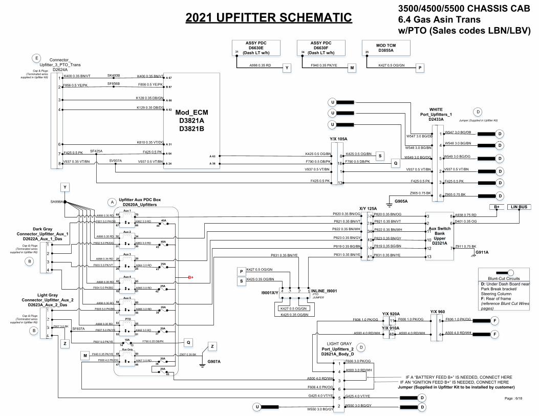
2021 UPFITTER SCHEMATIC 3500/4500/5500 CHASSIS CAB6.7 Diesel w/o PTO
ASSY PDC D6630E
(Dash LT w/h)
ASSY PDC D6630F
(Dash LT w/h)
Y M
31 34
A998 0.35 RD F940 0.35 PK/YE
Mod_ECMD3838AD3838B
Upfitter Aux PDC BoxD2620A_Upfitters
B 94
B 57
F425B 0.5 PK
V937P 0.5 VT/BN
1
F425B 0.5 PK
V937P 0.5 VT/BN
13
Y/X 105A
2
3
6
V937 0.5 VT/BN
F425 0.5 PK
WHITEPort_Upfitters_1
D2433A
D
Jumper (Supplied in Upfitter Kit)
G905A
Z905 0.75 BK
V937 0.5 VT/BN
Z905 0.75 BK
Aux 1
A
Y
Aux 2
Aux 3
Aux 4
Aux 5
AUX 6
Run Only
Cap & Plugs(Terminated wires
supplied in Upfitter Kit)
Dark GrayConnector_Upfitter_Aux_1
D2622A_Aux_1_Das
B
1
2
4
3
F601 5.0 PK/DB
F602 5.0 PK/DG
F603 5.0 PK/VT
F604 5.0 PK/BG
B
1
2
4
3
Cap & Plugs(Terminated wires
supplied in Upfitter Kit)
Light GrayConnector_Upfitter_Aux_2
D2623A_Aux_2_DasF605 5.0 PK/BN
A998 0.35 RD
A998 0.35 RD
A998 0.35 RD
A998 0.35 RD
A998 0.35 RD
A998 0.35 RD
68
67
70
66
32
31
34
30
27
26
29
25
63
62
65
61
58
57
60
56
53
52
55
51
48
47
50
46
SA998A
F607 5.0 PK/YE
Z
Z907 3.0 BK
M F940 0.35 PK/YE
40A
44A962 3.0 RD
40A
43
25A
41
25A
42
20A
39
20A
37
20A
36
20A
45
A963 3.0 RD
A965 3.0 RD
A966 3.0 RD
A967 3.0 RD
A964 3.0 RD
G907A
Z907 0.35 BK
Z
B+
37
38
40
36
41
P821 0.35 BN/VT
P822 0.35 BN/WH
P823 0.35 BN/GY
P819 0.35 BG/BN
Aux SwitchBankUpper
D2321A
3
2
11
10
12
13
12
P831 0.35 BN/YE P831 0.35 BN/YE
P831 0.35 BN/YE
B+ LIN BUS
A938 0.75 RD
D401 0.35 OG8
6
7G911A
I9001X/Y INLINE_I9001Non PTO JUMPER
DPort_Upfitters_2D2621A_Body_D
LIGHT GRAY
Y/X 960
A500 4.0 RD/WH
Y/X 920A
Y/X 910A
1
4
3
6
5
F606 1.0 PK/OG
A500 4.0 RD/WH
A500 4.0 RD/WH
F606 4.0 PK/OG
G425 4.0 VT/YE
A500 3.0 RD/WH
X/Y 125A
Blunt-Cut CircuitsD: Under Dash Board near Park Break bracket/Steering ColumnF: Rear of frame(reference Blunt Cut Wires pages)
F606 4.0 PK/OG
11
48
5
4
F606 3.0 PK/OG
IF A “BATTERY FEED B+” IS NEEDED, CONNECT HERE IF AN “IGNITION FEED B+” IS NEEDED, CONNECT HEREJumper (Supplied in Upfitter Kit to be installed by customer)
G425 4.0 VT/YE
F
F
F606 1.0 PK/OGF606 1.0 PK/OG
A500 4.0 RD/WH
Z911 0.75 BK
P820 0.35 BN/OG
P821 0.35 BN/VT
P822 0.35 BN/WH
P823 0.35 BN/GY
P819 0.35 BG/BN
P831 0.35 BN/YE
34
P820 0.35 BN/OG
D
D
D
F425 0.5 PK
D
A968 3.0 RD
Page : 7/18
Ckt F790 give away in Dash LT harness
W547 3.0 BG/DB
W549 3.0 BG/DG
D
D
D
W548 3.0 BG/BN
W547 3.0 BG/DB
U
W548 3.0 BG/BN
U
W549 3.0 BG/DG
U
W550 3.0 BG/GY DW550 3.0 BG/GYU 2
1
4
5
2021 UPFITTER SCHEMATIC
ASSY PDC D6630E
(Dash LT w/h)
ASSY PDC D6630F
(Dash LT w/h)
Y M
31 34
A998 0.35 RD F940 0.35 PK/YE
Upfitter Aux PDC Box
D2620A_Upfitters
Aux 1
A
Y
Aux 2
Aux 3
Aux 4
Aux 5
Aux 6
Run Only
Dark GrayConnector_
Upfitter_Aux_1D2622A_Aux_1_Das
B
1
2
4
3
F601 5.0 PK/DB
F602 5.0 PK/DG
F603 5.0 PK/VT
F604 5.0 PK/BG
B
1
2
4
3
Light GrayConnector_
Upfitter_Aux_2D2623A_Aux_2_Das
F605 5.0 PK/BN
A998 0.35 RD
A998 0.35 RD
A998 0.35 RD
A998 0.35 RD
A998 0.35 RD
A998 0.35 RD
68
67
70
66
32
31
34
30
27
26
29
25
63
62
65
61
58
57
60
56
53
52
55
51
48
47
50
46
SA998A
F607 5.0 PK/YE
Z
Z907 3.0 BK
M F940 0.35 PK/YE
40A
44A962 3.0 RD
40A
43
25A
41
25A
42
20A
39
20A
37
20A
36
20A
45
A963 3.0 RD
A965 3.0 RD
A966 3.0 RD
A967 3.0 RD
A964 3.0 RD
G907A
Z907 0.35 BK
Z
B+
37
38
40
36
41
P821 0.35 BN/VT
P822 0.35 BN/WH
P823 0.35 BN/GY
P819 0.35 BG/BN
Aux SwitchBankUpper
D2321A
3
2
11
10
12
13
12
P831 0.35 BN/YE
B+ LIN BUS
A938 0.75 RD
D401 0.35 OG8
6
7G911A
I9001X INLINE_I9001PTO JUMPER
DPort_Upfitters_2D2621A_Body_D
LIGHT GRAY
Y/X 960
A500 4.0 RD/WH
Y/X 920A
Y/X 910A
1
4
3
6
5
F606 1.0 PK/OG
A500 4.0 RD/WH
A500 4.0 RD/WH
F606 4.0 PK/OG
G425 4.0 VT/YE
A500 3.0 RD/WH
X/Y 125A
Blunt-Cut CircuitsD: Under Dash Board near Park Break bracket/Steering ColumnF: Rear of frame(reference Blunt Cut Wires pages)
F606 4.0 PK/OG
11
48
5
4
F606 3.0 PK/OG
IF A “BATTERY FEED B+” IS NEEDED, CONNECT HERE IF AN “IGNITION FEED B+” IS NEEDED, CONNECT HEREJumper (Supplied in Upfitter Kit to be installed by customer)
G425 4.0 VT/YE
F
F
F606 1.0 PK/OGF606 1.0 PK/OG
A500 4.0 RD/WH
Z911 0.75 BK
P820 0.35 BN/OG
P821 0.35 BN/VT
P822 0.35 BN/WH
P823 0.35 BN/GY
P819 0.35 BG/BN
P831 0.35 BN/YE
34
P820 0.35 BN/OG
D
3500/4500/5500 CHASSIS CAB6.4L Gas – w/o PTO
A968 3.0 RD
K
Page : 8/18
P831 0.35 BN/YE
P831 0.35 BN/YE
Mod_ECMD3821AD3821B
A 64
A 24
F425B 0.5 PK
V937P 0.5 VT/BN
1
F425B 0.5 PK
V937P 0.5 VT/BN
13
18
Y/X 105A
QF790 0.5 DB/PK
2
3
6
V937 0.5 VT/BN
F425 0.5 PK
WHITE Port_Upfitters_1
D2433A
D
G905A
V937 0.5 VT/BN
Z905 0.75 BK
D
D
D
F425 0.5 PK
Ckt F790 give away in Dash LT harness
Z905 0.75 BK
Jumper (Supplied in Upfitter Kit)
W547 3.0 BG/DB
W549 3.0 BG/DG
D
D
D
W548 3.0 BG/BN
W547 3.0 BG/DB
U
W548 3.0 BG/BN
U
W549 3.0 BG/DG
U
5
4
1
W550 3.0 BG/GY DW550 3.0 BG/GYU 2
2021 UPFITTER SCHEMATIC
ASSY PDC D6630E
(Dash LT w/h)
ASSY PDC D6630F
(Dash LT w/h)
Y M
31 34
A998 0.35 RD F940 0.35 PK/YE
Upfitter Aux PDC Box
D2620A_Upfitters
Aux 1
A
Y
Aux 2
Aux 3
Aux 4
Aux 5
Aux 6
Run Only
Dark GrayConnector_
Upfitter_Aux_1D2622A_Aux_1_Das
B
1
2
4
3
F601 5.0 PK/DB
F602 5.0 PK/DG
F603 5.0 PK/VT
F604 5.0 PK/BG
B
1
2
4
3
Light GrayConnector_
Upfitter_Aux_2D2623A_Aux_2_Das
F605 5.0 PK/BN
A998 0.35 RD
A998 0.35 RD
A998 0.35 RD
A998 0.35 RD
A998 0.35 RD
A998 0.35 RD
68
67
70
66
32
31
34
30
27
26
29
25
63
62
65
61
58
57
60
56
53
52
55
51
48
47
50
46
SA998A
F607 5.0 PK/YE
Z
Z907 3.0 BK
M F940 0.35 PK/YE
40A
44A962 3.0 RD
40A
43
25A
41
25A
42
20A
39
20A
37
20A
36
20A
45
A963 3.0 RD
A965 3.0 RD
A966 3.0 RD
A967 3.0 RD
A964 3.0 RD
G907A
Z907 0.35 BK
Z
B+
37
38
40
36
41
P821 0.35 BN/VT
P822 0.35 BN/WH
P823 0.35 BN/PY
P819 0.35 BG/BN
Aux SwitchBankUpper
D2321A
3
2
11
10
12
13P831 0.35 BN/YE
B+ LIN BUS
A938 0.75 RD
D401 0.35 OG8
6
7G911A
DPort_Upfitters_2D2621A_Body_D
LIGHT GRAY
Y/X 960
A500 4.0 RD/WH
Y/X 920A
Y/X 910A
1
4
3
6
5
F606 1.0 PK/OG
A500 4.0 RD/WH
A500 4.0 RD/WH
F606 4.0 PK/OG
G425 4.0 VT/YE
A500 3.0 RD/WH
X/Y 125A
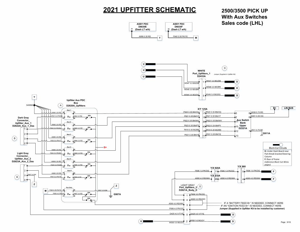
Blunt-Cut CircuitsD: Under Dash Board near Park Break bracket/Steering ColumnF: Rear of frame(reference Blunt Cut Wires pages)
F606 4.0 PK/OG
11
48
5
4
F606 3.0 PK/OG
IF A “BATTERY FEED B+” IS NEEDED, CONNECT HERE IF AN “IGNITION FEED B+” IS NEEDED, CONNECT HEREJumper (Supplied in Upfitter Kit to be installed by customer)
G425 4.0 VT/YE
F
F
F606 1.0 PK/OGF606 1.0 PK/OG
A500 4.0 RD/WH
Z911 0.75 BK
P820 0.35 BN/OG
P821 0.35 BN/VT
P822 0.35 BN/WH
P823 0.35 BN/PY
P819 0.35 BG/BN
P831 0.35 BN/YE
34
P820 0.35 BN/OG
D
2500/3500 PICK UPWith Aux SwitchesSales code (LHL)
A968 3.0 RD
Page : 9/18
WHITEPort_Upfitters_1
D2433A
D
Jumper (Supplied in Upfitter Kit)
W547 3.0 BG/DB
W549 3.0 BG/DG
D
D
D
W548 3.0 BG/BN
W547 3.0 BG/DB
U
W548 3.0 BG/BN
U
W549 3.0 BG/DG
U
5
4
1
W550 3.0 BG/GY DW550 3.0 BG/GYU 2
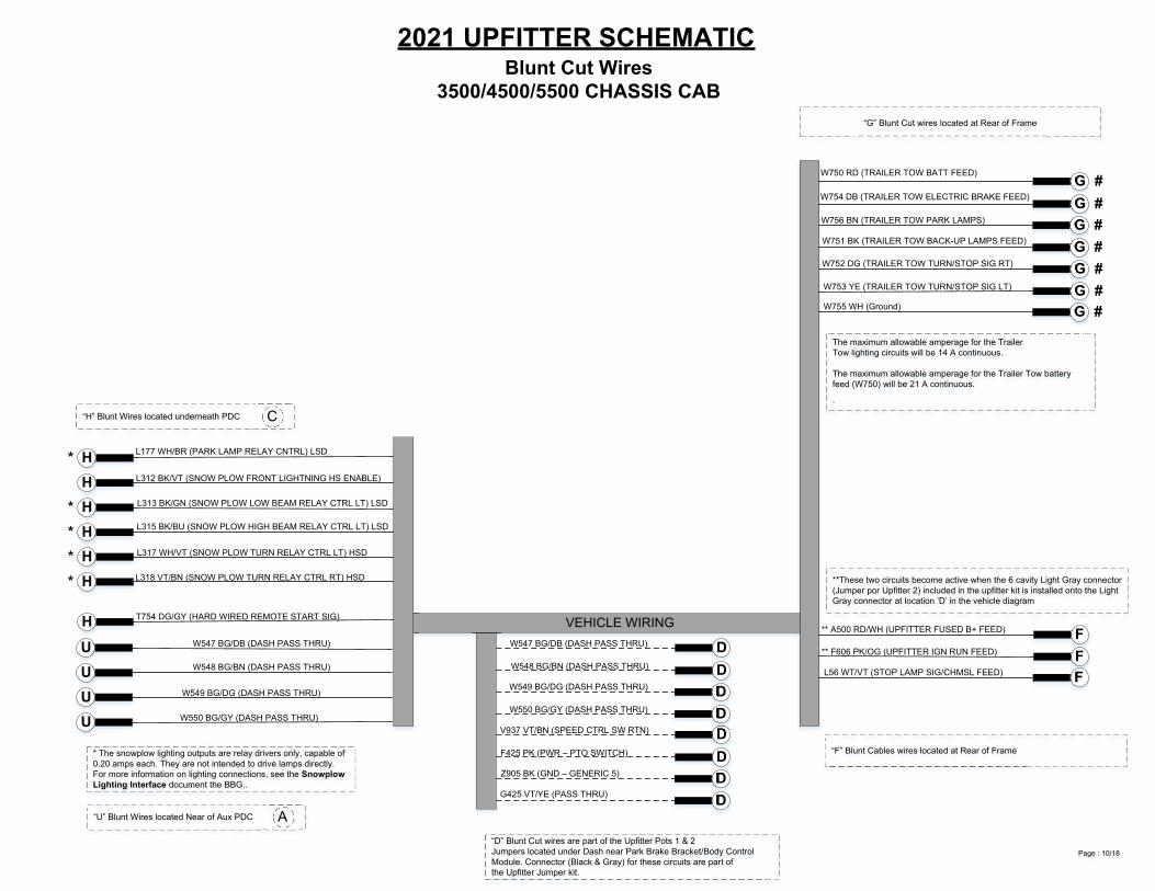
2021 UPFITTER SCHEMATICBlunt Cut Wires
3500/4500/5500 CHASSIS CAB“G” Blunt Cut wires located at Rear of Frame
G #G #G #G #G #G #G #
W750 RD (TRAILER TOW BATT FEED)
W754 DB (TRAILER TOW ELECTRIC BRAKE FEED)
W756 BN (TRAILER TOW PARK LAMPS)
W751 BK (TRAILER TOW BACK-UP LAMPS FEED)
W752 DG (TRAILER TOW TURN/STOP SIG RT)
W753 YE (TRAILER TOW TURN/STOP SIG LT)
W755 WH (Ground)
**These two circuits become active when the 6 cavity Light Gray connector(Jumper por Upfitter 2) included in the upfitter kit is installed onto the LightGray connector at location ‘D’ in the vehicle diagram
FFF
** A500 RD/WH (UPFITTER FUSED B+ FEED)
** F606 PK/OG (UPFITTER IGN RUN FEED)
L56 WT/VT (STOP LAMP SIG/CHMSL FEED)
“F” Blunt Cables wires located at Rear of FrameDDDD
“D” Blunt Cut wires are part of the Upfitter Pots 1 & 2Jumpers located under Dash near Park Brake Bracket/Body Control Module. Connector (Black & Gray) for these circuits are part ofthe Upfitter Jumper kit.
V937 VT/BN (SPEED CTRL SW RTN)
F425 PK (PWR – PTO SWITCH)
Z905 BK (GND – GENERIC 5)
G425 VT/YE (PASS THRU)
VEHICLE WIRING
H*HH*H*H*H*
H
L177 WH/BR (PARK LAMP RELAY CNTRL) LSD
L312 BK/VT (SNOW PLOW FRONT LIGHTNING HS ENABLE)
L313 BK/GN (SNOW PLOW LOW BEAM RELAY CTRL LT) LSD
L315 BK/BU (SNOW PLOW HIGH BEAM RELAY CTRL LT) LSD
L317 WH/VT (SNOW PLOW TURN RELAY CTRL LT) HSD
L318 VT/BN (SNOW PLOW TURN RELAY CTRL RT) HSD
T754 DG/GY (HARD WIRED REMOTE START SIG)
“H” Blunt Wires located underneath PDC C
* The snowplow lighting outputs are relay drivers only, capable of 0.20 amps each. They are not intended to drive lamps directly. For more information on lighting connections, see the Snowplow Lighting Interface document the BBG..
Page : 10/18
DDDD
W547 BG/DB (DASH PASS THRU)
W548 BG/BN (DASH PASS THRU)
W549 BG/DG (DASH PASS THRU)
W550 BG/GY (DASH PASS THRU)
UUUU
W547 BG/DB (DASH PASS THRU)
W548 BG/BN (DASH PASS THRU)
W549 BG/DG (DASH PASS THRU)
W550 BG/GY (DASH PASS THRU)
“U” Blunt Wires located Near of Aux PDC A
The maximum allowable amperage for the TrailerTow lighting circuits will be 14 A continuous.
The maximum allowable amperage for the Trailer Tow battery feed (W750) will be 21 A continuous.
.

2021 UPFITTER SCHEMATICBlunt Cut Wires
2500/3500 Pickup Box-off (Sales Code XBC)“G” Blunt Cut wires located at Rear of Frame
G #G #G #G #G #G #G #
W750 RD (TRAILER TOW BATT FEED)
W754 DB (TRAILER TOW ELECTRIC BRAKE FEED)
W756 BN (TRAILER TOW PARK LAMPS)
W751 BK (TRAILER TOW BACK-UP LAMPS FEED)
W752 DG (TRAILER TOW TURN/STOP SIG RT)
W753 YE (TRAILER TOW TURN/STOP SIG LT)
W755 WH (Ground)
**These two circuits become active when the 6 cavity Light Gray connector(Jumper por Upfitter 2) included in the upfitter kit is installed onto the LightGray connector at location ‘D’ in the vehicle diagram
FF
** A500 RD/WH (UPFITTER FUSED B+ FEED)
** F606 PK/OG (UPFITTER IGN RUN FEED)
“F” Blunt Cables wires located at Rear of Frame
D
“D” Blunt Cut wires are part of the Upfitter Ports 1 & 2Jumpers located under Dash near Park Brake Bracket/Body Control Module. Connector (Black & Gray) for these circuits are part ofthe Upfitter Jumper kit.
G425 VT/YE (PASS THRU)
VEHICLE WIRING
H*HH*H*H*H*H
L177 WH/BR (PARK LAMP RELAY CNTRL) LSD
L312 BK/VT (SNOW PLOW FRONT LIGHTNING HS ENABLE)
L313 BK/GN (SNOW PLOW LOW BEAM RELAY CTRL LT) LSD
L315 BK/BU (SNOW PLOW HIGH BEAM RELAY CTRL LT) LSD
L317 WH/VT (SNOW PLOW TURN RELAY CTRL LT) HSD
L318 VT/BN (SNOW PLOW TURN RELAY CTRL RT) HSD
T754 DG/GY (NOT USED)
“H” Blunt Wires located underneath PDC C
“M” Blunt Cut wire located at Right (Passenger Side), in thesecond crossmember from rear to front.
M L56 WH/VT (STOP LAMP SIG/CHMSL FEED)
Page : 11/18
UUUU
W547 BG/DB (DASH PASS THRU)
W548 BG/BN (DASH PASS THRU)
W549 BG/DG (DASH PASS THRU)
W550 BG/GY (DASH PASS THRU)
“U” Blunt Wires located Near of Aux PDC A
DDDD
W547 BG/DB (DASH PASS THRU)
W548 BG/BN (DASH PASS THRU)
W549 BG/DG (DASH PASS THRU)
W550 BG/GY (DASH PASS THRU)
The maximum allowable amperage for the TrailerTow lighting circuits will be 14 A continuous.
The maximum allowable amperage for the Trailer Tow battery feed (W750) will be 21 A continuous.
.
* The snowplow lighting outputs are relay drivers only, capable of 0.20 amps each. They are not intended to drive lamps directly. For more information on lighting connections, see the Snowplow Lighting Interface document the BBG..

2021 UPFITTER SCHEMATICBlunt Cut Wires
2500/3500 Pickup Box-onW/Auxiliary Switches (Sales Code LHL)
**These two circuits become active when the 6 cavity Light Gray connector(Jumper por Upfitter 2) included in the upfitter kit is installed onto the LightGray connector at location ‘D’ in the vehicle diagram
FF
** A500 RD/WH (UPFITTER FUSED B+ FEED)
** F606 PK/OG (UPFITTER IGN RUN FEED)
“F” Blunt Cables wires located at Rear of Frame
D
“D” Blunt Cut wires are part of the Upfitter Ports 1 & 2Jumpers located under Dash near Park Brake Bracket/Body Control Module. Connector (Black & Gray) for these circuits are part ofthe Upfitter Jumper kit.
G425 VT/YE (PASS THRU)
VEHICLE WIRING
H*HH*H*H*H*H
L177 WH/BR (PARK LAMP RELAY CNTRL) LSD
L312 BK/VT (SNOW PLOW FRONT LIGHTNING HS ENABLE)
L313 BK/GN (SNOW PLOW LOW BEAM RELAY CTRL LT) LSD
L315 BK/BU (SNOW PLOW HIGH BEAM RELAY CTRL LT) LSD
L317 WH/VT (SNOW PLOW TURN RELAY CTRL LT) HSD
L318 VT/BN (SNOW PLOW TURN RELAY CTRL RT) HSD
T754 DG/GY (NOT USED)
“H” Blunt Wires located underneath PDC C
“M” Blunt Cut wire located at Right (Passenger Side), in thesecond crossmember from rear to front.
M L56 WH/VT (STOP LAMP SIG/CHMSL FEED)
*THESE SNOW PLOW CIRCUITS ARE NOT AVAILABLE ONPOWER WAGON
*
Page : 12/18
DDDD
W547 BG/DB (DASH PASS THRU)
W548 BG/BN (DASH PASS THRU)
W549 BG/DG (DASH PASS THRU)
W550 BG/GY (DASH PASS THRU)
UUUU
W547 BG/DB (DASH PASS THRU)
W548 BG/BN (DASH PASS THRU)
W549 BG/DG (DASH PASS THRU)
W550 BG/GY (DASH PASS THRU)
“U” Blunt Wires located Near of Aux PDC A
* The snowplow lighting outputs are relay drivers only, capable of 0.20 amps each. They are not intended to drive lamps directly. For more information on lighting connections, see the Snowplow Lighting Interface document the BBG..

2021 UPFITTER SCHEMATICBlunt Cut Wires
2500/3500 Pickup Box-onW/O Auxiliary Swithces
VEHICLE WIRING
H*HH*H*H*H*
L177 WH/BR (PARK LAMP RELAY CNTRL) LSD
L312 BK/VT (SNOW PLOW FRONT LIGHTNING HS ENABLE)
L313 BK/GN (SNOW PLOW LOW BEAM RELAY CTRL LT) LSD
L315 BK/BU (SNOW PLOW HIGH BEAM RELAY CTRL LT) LSD
L317 WH/VT (SNOW PLOW TURN RELAY CTRL LT) HSD
L318 VT/BN (SNOW PLOW TURN RELAY CTRL RT) HSD
“H” Blunt Wires located underneath PDC C
“M” Blunt Cut wire located at Right (Passenger Side), in thesecond crossmember from rear to front.
M L56 WH/VT (STOP LAMP SIG/CHMSL FEED)
*THESE SNOW PLOW CIRCUITS ARE NOT AVAILABLE ONPOWER WAGON
The maximun allowable continuous amperage for theseSnow Plow circuits will be found under“ELECTRICAL/WIRING INFORMATION”, “ELECTRICALPOWER USAGE”, “AMPERAGE CAPACITY PER CIRCUIT”.
*
Page : 13/18
* The snowplow lighting outputs are relay drivers only, capable of 0.20 amps each. They are not intended to drive lamps directly. For more information on lighting connections, see the Snowplow Lighting Interface document the BBG..

2021 UPFITTER SCHEMATICUpfitter Jumper Harness Only
PTO Connector(Wire Insertion End of Up Fitter Cap)
E
1
2
4
3
5
6
8
7
K400 0.35 BN/VT (ENF – ACCEL PEDAL POS SNSR RTN 2)
F856 0.5 YE/PK (ENG – 5V ENGINE SNSR FEED SEC)
K128 0.5 DB/GN (ENG – REMOTE THROTTLE SWITCH SIGNAL)
K129 0.5 DB/DG (ENG – REMOTE THROTTLE SWITCH)
K119 0.5 GN/BK (ENG – MAXIMUN OPERATING SPEED SWITCH)
K810 0.5 VT/DG (ENG – ACCELERATOR INTERLOCK SWITCH)
F425 0.5 PK (PWR – POWER TAKEOFF SWITCH)
V937 0.35 VT/BN (SCS – SPEED CTRL SW RTN)
1
2
4
3
F601 3.0 PK/DB (RELAY 1 OUTPUT)
F602 3.0 PK/DG (RELAY 2 OUTPUT)
F603 3.0 PK/VT (RELAY 3 OUTPUT)
F604 3.0 PK/BG (RELAY 4 OUTPUT)
1
2
4
3
F605 3.0 PK/BN (RELAY 5 OUTPUT)
F607 3.0 PK/YE (RELAY 6 OR PTO RELAY OUTPUT)
Z907 3.0 BK (GND)
G425 3.0 VT/YE (Pass Thru)
B B
Dash_Dark GrayConnector_Upfitter Aux_1
(Wire Insertion End of Up Fitter Cap)
*Note – Each Circuit can handle maximumcontinuous current of 28A. Maximumcombined load for AUX Switches is 133A*The upfitter/customer is responsible forplacing the correct fuse in the correct
location depending on the actual load.
Dash_Light GrayConnector_Upfitter_2 Aux_2
(Wire Insertion End of Up Fitter Cap)
JumperPort_Upfitters_1
(Wire Insertion End of Up Fitter Cap)
D
White connector
1
2
4
3
5
6
W547 3.0 BG/DB (Dash Pass Thru)
V937 0.35 VT/BN (PTO /SEIU SW RTN)
F425 0.5 PK PTO/SEIU SWITCH)
W549 3.0 BG/DG (Dash Pass Thru)
Z905 0.75 BK (GROUND)
1
2
4
3
5
6
JumperPort_Upfitters_2
(Wire Insertion End Up Fitter Cap)
DLight Gray connector
F606 3.0 PK/OR (PWR – ATM UPFITTER IGN RUN FEED)
A500 3.0 RD/WH (PWR – BATT – ATM – UPFITTER FUSED FEED)
G425 4.0 12T VT/YL (Pass Thru)
JumperPTO
(Wire Insertion End of Up Fitter Cap)
K
Dark Gray
JumperNON-PTO
(Aux 6) (Wire Insertion End of Up Fitter Cap)
KDark Gray
THESE ARE NORMALLY NOT CUSTOMER REPLACED
1
2
4
3
K425 0.35 OG/BN
K427 0.5 OG/GN1
2
4
3
P831 0.35 BN/YE
Page : 14/18
W548 3.0 BG/BN (Dash Pass Thru)
W550 3.0 BG/GY (Dash Pass Thru)

2021 UPFITTER SCHEMATICPTO CONNECTOR Under the Vehicle at Transmission
Circuit Function and Pin – Out3500/4500/5500 CHASSIS CAB ONLY
Diesel/GasPCM
E
K119 0.5 GN/BK (ENG – MAXIMUM OPERATING SPEED SWITCH)
K129 0.5 DB/DG (ENG - REMOTE THROTTLE SWITCH)
K400 0.35 BN/YT (ENGINE – ACCEL PEDAL POS SNSR RTN 2)
F856 0.5 YE/PK (ENG – 5V ENGINE SNSR FEED SEC)
K810 0.5 VT/DG (ENG – ACCELERATOR INTERLOCK SWITCH)
F425 0.5 PK (PWR – POWER TAKEOFF SWITCH)
1
2
3
4
5
6
7
8V937 0.35 VT/BN (SCS – SPEED CTRL SW RTN)
Connector_Upfitter_3_PTO_Trans
D2624ACap & Plugs
(Terminated wiressupplied in Upfitter Kit)
Transmission – Dark GrayConnector_Upfitter_3PTO
(Wire Insertion End of Up Fitter Cap)
K128 0.5 DB/GN (ENG – REMOTE THROTTLE SWITCH SIGNAL)
Page : 15/18

2021 UPFITTER SCHEMATICBagged Upfitter Kit Detail
68512072
(8) Circuits for Up fitter Aux Connectors 1 & 2 – 5.0 mm (6), 4.0 mm (1), 3.0 mm (1)(8) Circuits for the Connector_Upfitter_3_PTO_Trans Connector – All 0.5 mm (2) PTO/Non-PTO Jumper Connectors(1) Port_Upfitter_2 – Gray Connector w/6 wires(1) Port_Upfitter_1 – Black Connector w/6 wires
The Vehicle has been equipped to ease the installation of a PTO by allowing convenient access to circuits needed without having to splice into the main harness.
Located left of Main PDC Box and along the left (Drivers Side) fender inner (location K) is a dark gray jumper connector that allows the vehicle function to switch between PTO and non-PTO operation, although this normally need not be accessed by the customer. If required, the jumpers are located in this upfitter kit. If necessary, verify proper jumper usage by reviewing jumper design on previous pages.
In the rear of chassis cabs and Pickups, you can find all required Trailer -Tow circuits, two (2) additional power circuits (1 Battery and 1 Ignition) and a Stop Lamp / CHMSL Feed Circuit.
In the Engine compartment you will find two (2) (A Light Gray and a Dark Gray) Upfitter AUX connectors (location B) which allow easy access to the switch bank and fuse box outputs, mating terminated circuits are included in this kit as needed. Connectors (Black & Gray) for these circuits are part of the upfitter jumper kit.
Warning about adding auxiliary batteries:An auxiliary battery may be used, however a battery isolation unit is not supplied and the auxiliary battery may discharge the truck battery when the engine is not running.
Ground Studs on the chassis/frame may be utilized as a grounding point with a 50A Maximum total load, see “Vehicle Ground Locations” section in the RAM Body Builder Guide, Electrical/Wiring Information.
Page : 16/18

WIRE SIZE REFERENCE
Page : 17/18
WIRE GAUGE US (AWG)WIRE GAUGE METRIC Only Copper (mm)
WIRE GAUGECopper + Insulation (mm)
22 0.35 1.320 0.5 1.619 0.75 1.918 0.8 216 1 2.115 1.5 2.414 2 2.613 2.5 312 3 3.3
4 3.710 5 4.2
6 4.38 8 5.5
10 66 13
15 716 7.9
4 193 25 9.4
30 112 32
35 11.61 40 12.41/0 50 13.52/0 623/0 70 15.5

Wire Color Abbreviations
Page : 18/18