Embed Size (px)
Citation preview

TB 11-5820-890-20-80
1 JULY 2000
TECHNICAL BULLETIN
COMBAT NET RADIO
INSTALLATION INSTRUCTIONS FORINSTALLATION KIT, ELECTRONIC EQUIPMENT,
MK-2531/VRC (NSN 5895-01-227-5841) (EIC: N/A)TO PERMIT INSTALLATION OF
RADIO SET AN/VRC-87/88/90 SERIES IN A
TRUCK, VAN, 2 1/2 TON, 6x6, SHOP: M109 AND M109A1/A2/A3
ANDTRUCK, VAN, 5 TON, 6x6, EXPANSIBLE:
M820 AND M820A1/A2/A3
Approved for public release; distribution is unlimited.
HEADQUARTERS, DEPARTMENT OF THE ARMY

TECHNICAL BULLETIN
NO. 11-5820-890-20-80
*TB 11–5820–890–20–80HEADQUARTERS,
DEPARTMENT OF THE ARMYWASHINGTON, DC, 1 JULY 2000
i
INSTALLATION INSTRUCTIONS FORINSTALLATION KIT, ELECTRONIC EQUIPMENT,
MK-2531/VRC (NSN 5895-01-227-5841) (EIC: N/A)TO PERMIT INSTALLATION OF
RADIO SET AN/VRC-87/88/90 SERIESINTO
TRUCK, VAN, 2 1/2 TON, 6x6, SHOP:M109 AND M109A1/A2/A3
ANDTRUCK, VAN, 5 TON, 6x6, EXPANSIBLE;
M820 AND M820A1/A2/A3
REPORTING OF ERRORS AND RECOMMENDING IMPROVEMENTS
You can help improve this manual. If you find any mistakes, or if you know of a way to improve the procedures, pleaselet us know. Mail your letter, DA Form 2028 (Recommended Changes to Publications and Blank Forms) or DA 2028–2located in back of this manual direct to: Commander, US Army Communications–Electronics Command Fort Mon-mouth, ATTN: AMSEL–LC–LEO–D–CS–CFO, Fort Monmouth, New Jersey 07703–5000. The Fax number is732–532–1413, DSN 992–1413. You may also e–mail your recommendation to AMSEL–LC–LEO–PUBS–[email protected].
In either case a reply will be furnished direct to you.
TABLE OF CONTENTS
Subject Section Page
Scope 0.1 1. . . . . . . . . . . . . . . . . . . . . . . . . . . . . . . . . . . . . . . . . . . . . . . . . . . . . . . . . . . . . . . .
General Information 0.2 1. . . . . . . . . . . . . . . . . . . . . . . . . . . . . . . . . . . . . . . . . . . . . . . . . . . .
Maintenance Forms, Records and Reports 0.3 1. . . . . . . . . . . . . . . . . . . . . . . . . . . . . . . .
Reports of Maintenance and Unsatisfactory Equipment 0.3.1 1. . . . . . . . . . . . . . . . . . . . .
Report of Packing and Handling Deficiencies 0.3.2 1. . . . . . . . . . . . . . . . . . . . . . . . . . . . . .
Discrepancy in Transportation Deficiency Report (TDR) (SF 361) 0.3.3 1. . . . . . . . . . . . .
Consolidated Index of Army Publications 0.4 1. . . . . . . . . . . . . . . . . . . . . . . . . . . . . . . . . .
Purpose of Installation 1. 2. . . . . . . . . . . . . . . . . . . . . . . . . . . . . . . . . . . . . . . . . . . . . . . . . .
End Item or System to be Modified 2. 2. . . . . . . . . . . . . . . . . . . . . . . . . . . . . . . . . . . . . . .
Application Times 3. 2. . . . . . . . . . . . . . . . . . . . . . . . . . . . . . . . . . . . . . . . . . . . . . . . . . . . . .
Time for Completion of Installation 3.1 2. . . . . . . . . . . . . . . . . . . . . . . . . . . . . . . . . . . . . . . .
Time for Installation of One Assembly or Component 3.2 2. . . . . . . . . . . . . . . . . . . . . . .
Preparation for Installation 4. 2. . . . . . . . . . . . . . . . . . . . . . . . . . . . . . . . . . . . . . . . . . . . . . .
Preparation of Vehicle 4.1 2. . . . . . . . . . . . . . . . . . . . . . . . . . . . . . . . . . . . . . . . . . . . . . . . . .
Preparation of MK 4.2 2. . . . . . . . . . . . . . . . . . . . . . . . . . . . . . . . . . . . . . . . . . . . . . . . . . . . . .
MK, Distribution, and Consumables 4.3 3. . . . . . . . . . . . . . . . . . . . . . . . . . . . . . . . . . . . . .
Tools and Test, Measurement and Diagnostic Equipment (TMDE)
Required 4.4 10. . . . . . . . . . . . . . . . . . . . . . . . . . . . . . . . . . . . . . . . . . . . . . . . . . . . . . . . . . . . . .
Installation Procedures 5. 11. . . . . . . . . . . . . . . . . . . . . . . . . . . . . . . . . . . . . . . . . . . . . . . . . .
Installation of Antenna AS-3900/VRC (antenna) 5.1 14. . . . . . . . . . . . . . . . . . . . . . . . . . .
Installation of Antenna Base (M109 Series) 5.1.1 14. . . . . . . . . . . . . . . . . . . . . . . . . . . . . . . .
Installation of Antenna Base (M820 Series) 5.1.2 17. . . . . . . . . . . . . . . . . . . . . . . . . . . . . . . .
Installation of Top Antenna Assembly 5.1.3 20. . . . . . . . . . . . . . . . . . . . . . . . . . . . . . . . . . . . .
Installation of Electrical Equipment Shelf (radio shelf) 5.2 21. . . . . . . . . . . . . . . . . . . . . . .
Installation of Radio Shelf (M109 Series) 5.2.1 21. . . . . . . . . . . . . . . . . . . . . . . . . . . . . . . . . .
Installation of Radio Shelf (M820 Series) 5.2.2 27. . . . . . . . . . . . . . . . . . . . . . . . . . . . . . . . . .
Installation of Mounting Base, Electrical Equipment MT-6352/VRC
(mounting base) 5.3 33. . . . . . . . . . . . . . . . . . . . . . . . . . . . . . . . . . . . . . . . . . . . . . . . . . . . . . .
________________
*This manual supersedes TB 11–5820–890–20–80, dated 1 September 1993.

TB 11-5820-890-20-80
ii
TABLE OF CONTENTS Continued
Installation of Cables 5.4 35. . . . . . . . . . . . . . . . . . . . . . . . . . . . . . . . . . . . . . . . . . . . . . . . . . .
Installation of Cables(M109 Series) 5.4.1 35. . . . . . . . . . . . . . . . . . . . . . . . . . . . . . . . . . . . . . .
Installation of Cables(M820 Series) 5.4.2 38. . . . . . . . . . . . . . . . . . . . . . . . . . . . . . . . . . . . . . .
Installation of Loudspeaker, Permanent Magnet LS-454/U (speaker) 5.5 42. . . . . . . . .
Installation of Loudspeaker, Control Unit LS-671/VRC 5.6 43. . . . . . . . . . . . . . . . . . . . . .
Post-Installation and Checkout 5.7 44. . . . . . . . . . . . . . . . . . . . . . . . . . . . . . . . . . . . . . . . . .
Appendix A. References A1. . . . . . . . . . . . . . . . . . . . . . . . . . . . . . . . . . . . . . . . . . . . . . . .
LIST OF ILLUSTRATIONS
Figure Title Page
4-1(1) MK Illustrated Parts List 6. . . . . . . . . . . . . . . . . . . . . . . . . . . . . . . . . . . . . . . . . . . . . . . . . . . . . . . . . . .
4-1(2) MK Illustrated Parts List 7. . . . . . . . . . . . . . . . . . . . . . . . . . . . . . . . . . . . . . . . . . . . . . . . . . . . . . . . . . .
4-1(3) MK Illustrated Parts List 8. . . . . . . . . . . . . . . . . . . . . . . . . . . . . . . . . . . . . . . . . . . . . . . . . . . . . . . . . . .
4-2 Illustrated Parts List for Table 4-2 9. . . . . . . . . . . . . . . . . . . . . . . . . . . . . . . . . . . . . . . . . . . . . . . . . .
5-1(1) MK and Radio Installation: MK and Radio Equipment Locations - M109 Series 11. . . . . . . . .
5-1(2) MK and Radio Installation: Mk and Radio Equipment Locations - M820 Series 12. . . . . . . . .
5-1(3) MK and Radio Installation: Radio Equipment Locations - M109/M820 Series 13. . . . . . . . . . .
5-2(1) Antenna Base Installation: M109 Series: Installing Brackets 14. . . . . . . . . . . . . . . . . . . . . . . . . . .
5-2(2) Antenna Base Installation: M109 Series: Installing Antenna Base and OE-254 Adapter 16. .
5-3(1) Antenna Base Installation - M820 Series: Installing Brackets 18. . . . . . . . . . . . . . . . . . . . . . . . .
5-3(1) Antenna Base Installation - M820 Series: Installing Antenna Base and OE-254 Adapter 19.
5-4 Top Antenna Assembly Installation 20. . . . . . . . . . . . . . . . . . . . . . . . . . . . . . . . . . . . . . . . . . . . . . . . .
5-5(1) Typical Radio Shelf Installation - M109 Series: Drilling Pattern (inside) 21. . . . . . . . . . . . . . . . .
5-5(2) Typical Radio Shelf Installation - M109 Series: Drilling Pattern (outside) 22. . . . . . . . . . . . . . .
5-5(3) Typical Radio Shelf Installation - M109 Series: Installing Channels and Angle Brackets 23. .
5-5(4) Typical Radio Shelf Installation - M109 Series: Installing Radio Shelf 24. . . . . . . . . . . . . . . . . .
5-6(1) Alternate Radio Shelf Installations - M109 Series 25. . . . . . . . . . . . . . . . . . . . . . . . . . . . . . . . . . . .
5-6(2) Alternate Radio Shelf Installations - M109 Series 26. . . . . . . . . . . . . . . . . . . . . . . . . . . . . . . . . . . .
5-7(1) Typical Radio Shelf Installation - M820 Series: Drilling Pattern (inside) 27. . . . . . . . . . . . . . . . .
5-7(2) Typical Radio Shelf Installation - M820 Series: Installing Angle Brackets 28. . . . . . . . . . . . . . .
5-7(3) Typical Radio Shelf Installation - M820 Series: Installing Radio Shelf 30. . . . . . . . . . . . . . . . . .
5-8(1) Alternate Radio Shelf Installations - M820 Series 31. . . . . . . . . . . . . . . . . . . . . . . . . . . . . . . . . . . .
5-8(2) Alternate Radio Shelf Installations - M820 Series 32. . . . . . . . . . . . . . . . . . . . . . . . . . . . . . . . . . . .
5-9 Mounting Base Installation 33. . . . . . . . . . . . . . . . . . . . . . . . . . . . . . . . . . . . . . . . . . . . . . . . . . . . . . . .
5-10(1) Cable Installation - M109 Series: Exterior Cabling 35. . . . . . . . . . . . . . . . . . . . . . . . . . . . . . . . . .
5-10(2) Cable Installation - M109 Series: Interior Cabling 37. . . . . . . . . . . . . . . . . . . . . . . . . . . . . . . . . . .
5-11(1) Cable Installation - M820 Series: RF and Power Cabling 39. . . . . . . . . . . . . . . . . . . . . . . . . . . . .
5-12(1) Speaker Installation - A 42. . . . . . . . . . . . . . . . . . . . . . . . . . . . . . . . . . . . . . . . . . . . . . . . . . . . . . . . . .
5-12(2) Speaker Installation - B 42. . . . . . . . . . . . . . . . . . . . . . . . . . . . . . . . . . . . . . . . . . . . . . . . . . . . . . . . . .
5-13 Speaker Installation 43. . . . . . . . . . . . . . . . . . . . . . . . . . . . . . . . . . . . . . . . . . . . . . . . . . . . . . . . . . . . . .
5-14 Cable Diagram: For AN/VRC-87/88/90 Series 45. . . . . . . . . . . . . . . . . . . . . . . . . . . . . . . . . . . . . .
LIST OF TABLES
Table Title Page
4-1 Parts List for Installation of Radio Set AN/VRC-87/88/90 Series 4. . . . . . . . . . . . . . . . . . . . . .
4-2 Additional Items Required for Installation of �D" and �F" Radio Sets 9. . . . . . . . . . . . . . . . . . .

TB 11-5820-890-20-80
1
0.1 SCOPE.
This technical bulletin provides Installation Instructions for Installation Kit, Electronic Equipment, MK-2531/VRC,
commonly referred to as the Mounting Kit (MK). The MK shall be installed into the following type of vehicle(s):
� Truck, Van, Shop, 2 1/2 Ton, 6x6, M109
� Truck, Van, Shop, 2 1/2 Ton, 6x6, M109A1
� Truck, Van, Shop, 2 1/2 Ton, 6x6, M109A2
� Truck, Van, Shop, 2 1/2 Ton, 6x6, M109A3
� Truck, Van, Expansible, 5 Ton, 6x6, M820
� Truck, Van, Expansible, 5 Ton, 6x6, M820A1
� Truck, Van, Expansible, 5 Ton, 6x6, M820A2
� Truck, Van, Expansible, 5 Ton, 6x6, M820A3
The MK is used for installation of radio set components at field locations. The information contained in this technical
bulletin is the official authorization to perform the installation at the unit maintenance level.
NOTES
� This technical bulletin is not an authorization for requisition or turn-in of vehicles.
� This technical bulletin does not establish quantity or types of vehicles assigned to using units.
This technical bulletin does not contain information on the maintenance or replacement of the MKs. This information
is contained in the MAC of TM 11-5820-890-20-2, and RPSTL of TM 11-5820-890-20P.
0.2 GENERAL INFORMATION.
The MK becomes operable when all the radio set components are installed in the vehicle and correct power is
supplied. Refer to TM 11-5820-890-20-1 or TM 11-5820-890-20-4 for installation, Operational (OP) Check
instructions, and required maintenance procedures. Refer to TM 11-5820-890-20P for repair parts.
Included in the Radio Set AN/VRC-87/88/90 Series is:
� Radio Set AN/VRC-87/88/90 Series (for RT-1523(C)/U)
0.3 MAINTENANCE FORMS, RECORDS AND REPORTS.
0.3.1 Reports of Maintenance and Unsatisfactory Equipment. See section 4.2.2.3 for information.
0.3.2 Report of Packaging and Handling Deficiencies. See section 4.2.2.1 for information.
0.3.3 Discrepancy in Transportation Deficiency Report (TDR) (SF361). See section 4.2.2.2 for information.
0.4 CONSOLIDATED INDEX OF ARMY PUBLICATIONS.
Refer to the latest issue of DA Pam 25-30 to determine whether there are new changes, or additional publications
pertaining to the equipment.

TB 11-5820-890-20-80
2
1. PURPOSE OF INSTALLATION.
The Installation Kit, Electronic Equipment, MK-2531/VRC(MK) contains the items needed to mount Radio Set
AN/VRC- 87/88/90 Series in a Van, Truck, 2 1/2 Ton, 6x6, Shop: M109 and M109A1/A2/A3, and Van, Truck, 5 Ton,
6x6, Expansible: M820 and M820A1/A2/A3 (vehicle).
2. END ITEM OR SYSTEM TO BE MODIFIED.
Not applicable.
3. APPLICATION TIMES.
3.1�Time for Completion of Installation. Using two people, a total of 4.0 work hours is required. Typical vehicle
downtime is 4.5 hours.
3.2 Time for Installation of One Assembly or Component. The following table lists the time required to install one
component. All times have been rounded off to the nearest half hour. The sum of these times will not reflect the
typical vehicle downtime.
ITEM SECTION TIME
Antenna AS-3900/VRC 5.1
Mounting Base, Electrical Equipment MT-6352/VRC 5.3
Cables 5.4
1.0
1.5
1.0
4.�PREPARATION FOR INSTALLATION.
This section explains how to prepare the vehicle and MK for installation.
4.1�Preparation of Vehicle.�To prepare the vehicle for installation, insure that the site includes adequate lighting
and a power source when drilling is required. Inspect the vehicle for damage that could affect installation. Have any
such damage repaired before installing MK.
4.1.1�Items to be Removed.�Remove existing AN/VRC-12 radio family installation kit/harness. See TM
11-5820-401-20-2 for removing items used with intercom systems, or TM 11-5820-401-20-1 (used without
intercom systems), TM 9 2320-209-20 and TM 9-2320-260-20.
4.1.2�List of Items to be Retained. Not applicable.
4.2�Preparation of MK. To prepare MK, unpack, inspect and check inventory.
4.2.1�Precautions During Handling. Observe these steps to prevent equipment damage.
a.�Keep dust covers in place on connectors.
b.�Do not disassemble or modify parts in MK unless authorized to do so.
c.�Keep mounting hardware covered and protected until needed.
d.�When exposed to moisture, rain or salt water, keep all parts dry to prevent corrosion.

TB 11-5820-890-20-80
3
4.2.2�Unpack and Inspect Equipment.
4.2.2.1�Inspect Packaging for Evidence of Damage. Any shipping damage should be reported on SF364 Report
of Discrepancy (ROD) as prescribed in AR 735-11-2/DLAR 4140.55/SECNAVINST 4355.18/AFR 400-54/MCO
4430.3J.
4.2.2.2�Unpack and Inventory MK. If any item is missing, fill out and forward Transportation Deficiency Report
(TDR) (SF361) as described in AR 55-38/NAVSUPINST 4610.33C/AFR 75-18/MCO P4610.19D/DLAR 4500.15.
4.2.2.3�Examine Each Item for Damage. If any item is damaged, fill out and forward SF364 Report of Discrepancy
(ROD) as prescribed in AR 735-11-2/DLAR 4140.55/SECNAVINST 4355.18/AFR 400-54/MCO 4430.3J. All
damages should be reported as prescribed by DA Pam 738-750, as contained in Maintenance Management
Update.
4.3�MK, Distribution and Consumables.
4.3.1�Items Supplied in MK and/or Required for Installation. Use Table 4-1 and figure 4-1 to identify and
inventory MK parts supplied to install Radio Set AN/VRC-87/88/90 Series. Refer to Table 4-2 and Figure 4-2 to
identify additional items required to install for �D" and �F" Radio Sets.
4.3.2�Distribution and Issue Instructions.
a.�US Forces: Do not requisition MK. They will be shipped automatically.
b.�US Army Depots: Requisition MK through supply channels.
c.�Multiservice: Instructions shall be included for multiservice modifications.
d.�MAP/MAS Countries: Instructions shall be provided for MAP/MAS countries.

TB 11-5820-890-20-80
4
Table 4-1. Parts List for Installation of Radio Set AN/VRC-87/88/90 Series
5985–01–297–2971 Antenna AS–3900/VRC (A3017899–1) 1 PAOOFA 4–1, 25305–00–847–1159 Screw, Cap, Hexagon (3/8–16 x 1 3/4 in) 4 PAOZZA
MS35307–3655310–00–913–8881 Nut, Hexagon (3/8–16 in) MS51971–3 4 PAOZZA5310–00–061–1258 Washer, Lock, Internal/External–Toothed 8 PAOZZA
(3/8 in) MS45904–765310–00–889–2527 Washer, Lock, Internal/External–Toothed 2 PAOZZA
(5/16 in) MS45904–72 5306–00–225–9086 Bolt, Machine (5/16–24 x 5/8 in) MS90726–31 1 PAOZZA
(Not Used)5330–01–205–2864 Gasket (A3013655–1) 1 PAOZZA
5965–00–876–2375 Loudspeaker, Permanent Magnet LS–454/U 1 PAOZZA 4–1, 5
5975–01–188–8873 Mounting Base, Electrical Equipment 1 PAOOFA 4–1, 1MT–6352/VRC (A3013367–1)
5306–00–225–9089 Bolt, Machine (5/16–24 x 1 in) MS90726–34 5 PAOZZA5310–00–889–2527 Washer, Lock, Internal/External–Toothed 10 PAOZZA
(5/16 in) MS45904–72 5310–00–880–7746 Nut, Hexagon (5/16–24 in) MS51968–5 5 PAOZZA
(Not Used)
5995–01–219–1843 Cable Assembly, Power, Electrical 1 PAOZZA 4–1,15CX–13302/VRC (13 FT, 0 IN) (A3014039–2)
5995–01–219–7034 Cable Assembly, Radio Frequency 1 PAOZZA 4–1,16CG–3855/VRC (15 FT, 0 IN) (A3014031–7)
5985–01–306–3828 Adapter, Antenna - OE–254 (A3018320–1) 1 PAOZZA 4–1, 6
5306–00–225–9089 Bolt, Machine (5/16–24 x 1 in) MS90726–34 12 PAOZZA5306–00–225–9097 Bolt, Machine (5/16–24 x 2 1/2 in) MS90726–42 2 PAOZZA
Bracket, Mounting - Antenna (A3050655–1) 1 XBOZZA 4–1, 7Bracket, Mounting - Reinforcement (A3014121–1) 1 XBOZZA 4–1, 9Bracket, Multiple Angle (A3014541–1) 3 XBOZZA 4–1, 8Bracket, Multiple Angle (A3014540–1) 2 XBOZZA 4–1,13Bracket, Multiple Angle (A3014547–1) 1 XBOZZA 4–1,12
Channel, Structural (A3014123–1) 4 XBOZZA 4–1,105340–00–809–1490 Clamp, Loop (1/4–1/4 in) MS21333–98 7 PAOZZA5340–00–088–1254 Clamp, Loop (5/8–1/4 in) MS21333–104 9 PAOZZA5340–00–809–1494 Clamp, Loop (3/4–1/4 in) MS21333–105 4 PAOZZA
4020–01–341–8795 Fiber Rope Assembly, Single Leg (A3167672–1) 1 PAOZZA 4–1, 4
Grommet, Nonmetallic (A3046173) 2 XBOZZA5325–00–682–1854 Grommet, Nonmetallic (1/4 in) MS35489–65 1 PAOZZA5325–00–174–5315 Grommet, Nonmetallic (1/4 in) MS35489–7 1 PAOZZA
Grommet, Retainer (A3140057–1) 2 XBOZZA
NSN AND PART NUMBER
ITEM DESCRIPTION QUANTITYIN MK
SMR
CODE
FIGURE,
ITEM NO.

TB 11-5820-890-20-80
5
Table 4-1. Parts List for Installation of Radio Set AN/VRC-87/88/90 Series Continued
5965–00–043–3463 Handset H–250/U 1 PAOZZA 4–1, 3
5310–00–761–6882 Nut, Hexagon (1/4–20 in) MS51967–2 3 PAOZZA5310–00–880–7746 Nut, Hexagon (5/16–24 in) MS51968–5 4 PAOZZA
Nut, Plain, Plate (A3014122–1) 8 XBOZZA 4–1,11
5305–00–068–0502 Screw, Cap, Hexagon (1/4–20 x 3/4 in) 13 PAOZZAMS90725–6
5305–00–225–9099 Screw, Cap, Hexagon (5/16–24 x 3 in) 4 PAOZZAMS90726–44
5305–01–313–3976 Screw, Tapping, Thread Forming, Pan-Head 8 PAOZZA(5/16–12 x 1 in) MS51850–108
5305–00–432–4253 Screw, Tapping, Thread Forming, Hex-Head 20 PAOZZA(1/4–14 x 3/4 in) MS51861–67Shelf, Electrical Equipment (A3014542–1) 1 XBOZZA 4–1,14
5975–00–111–3208 Strap, Tiedown, Electrical Components 10 PAOZZAMS3367–5–9
5310–00–809–4058 Washer, Flat (1/4 in) MS27183–10 2 PAOZZA5310–00–081–4219 Washer, Flat (5/16 in) MS27183–12 21 PAOZZA5310–00–582–5965 Washer, Lock (1/4 in) MS35338–44 24 PAOZZA5310–00–407–9566 Washer, Lock (5/16 in) MS35338–45 17 PAOZZA5310–00–889–2528 Washer, Lock, Internal/External–Toothed 5 PAOZZA
(1/4 in) MS45904–68
NSNAND PART NUMBER
ITEM DESCRIPTION QUANTITY
IN MKSMR
CODEFIGURE,
ITEM NO.

TB 11-5820-890-20-80
6
4
3
1
2
5
6
7
Figure 4-1 (1).�MK Illustrated Parts List

TB 11-5820-890-20-80
7
14
12
11
10
9
8
13
Figure 4-1 (2).�MK Illustrated Parts List

TB 11-5820-890-20-80
8
Figure 4-1 (3).�MK Illustrated Parts List
T2
T1
P2
P2
P1
15
16

TB 11-5820-890-20-80
9
Table 4-2. Additional Items Required for Installation for �D" and �F" Radio Sets
NSNAND PART NUMBER
ITEM DESCRIPTIONQUANTITY CODE
SMRITEM NO.FIGURE,
Figure 4-2. Illustrated Parts List for Table 4-2
5995–01–222–1420 Loudspeaker, Control Unit LS–671/VRC 1 PAOFFA 4–2, 1(A3014065–1)
5995–01–219–4704 Cable Assembly, Special Purpose, Electrical 1 PAOZZA 4–2, 2CX–13292/VRC (6 FT, 0 IN) (A3014038–3)
P1
P2
2
1

TB 11-5820-890-20-80
10
4.3.3�Consumable Materials. The table below lists materials required for installation but not supplied with MK.
NSN NOMENCLATURE
8040-00-117-8510
6850-00-880-7616
8030-00-292-1102
Adhesive-Sealant, Clear, RTV
Silicone Compound, MIL-S-8660
Conductive Anti-seize Compound
4.4�Tools and Test, Measurement and Diagnostic Equipment (TMDE) Required. The following tools and TMDE
are needed for installation.
Radio Set*
Electric Grinder or Equivalent
Pocket Knife, Electrician’s
Screwdriver, No. 2 Point Phillips, 4 in
Screwdriver, 1/4 in Flatblade, 4 in
Pliers, Round Nose
Pliers, Diagonal Cutting
Wrench, Open/Box: 7/16 in1/2 in9/16 in5/16 in3/4 in
Handle, Socket WrenchSocket: 7/16 in
1/2 in9/16 in
Electric DrillDrill Bits: 3/16 in
1/4 in9/32 in11/32 in3/4 in1 1/4 in5/16 in13/32 in
NOMENCLATURE NSN QUANTITY
5110–00–240–5943
5120–00–234–8913
5120–00–222–8852
5120–00–240–6172
5110–00–965–0974
5120–00–228–95055120–00–228–95065120–00–228–95075120–00–228–95035120–00–228–9510
5120–00–240–53645120–00–227–67035120–00–237–09775120–00–227–6704
5130-00-889-89945133-00-227-9654
5133-00-227-9658
5133-00-222-93745133-00-227-9664
5133-00-227-9662
5133-00-227-9668
1
1
1
1
1
1
1
11111
1111
111111111
*�Use radio issued with your vehicle if available.
TB 11-5820-890-20-80
11
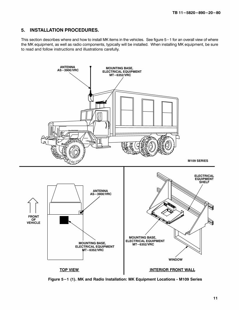
5.�INSTALLATION PROCEDURES.
This section describes where and how to install MK items in the vehicles. See figure 5-1 for an overall view of where
the MK equipment, as well as radio components, typically will be installed. When installing MK equipment, be sure
to read and follow instructions and illustrations carefully.
INTERIOR FRONT WALLTOP VIEW
WINDOW
Figure 5-1 (1). MK and Radio Installation: MK Equipment Locations � M109 Series
ANTENNA AS-3900/VRC
MOUNTING BASE,ELECTRICAL EQUIPMENT MT-6352/VRC
FRONTOF
VEHICLE
MOUNTING BASE,ELECTRICAL EQUIPMENT MT-6352/VRC
ANTENNA AS-3900/VRC
MOUNTING BASE,ELECTRICAL EQUIPMENT MT-6352/VRC
ELECTRICALEQUIPMENT
SHELF
M109 SERIES

TB 11-5820-890-20-80
12
5.�INSTALLATION PROCEDURES. Continued.
TOP VIEW FORWARD INTERIOR WALL
Figure 5-1 (2). MK and Radio Installation: MK Equipment Locations - M820 Series
FRONTOF
VEHICLE
ELECTRICALEQUIPMENT
SHELF
ANTENNAAS-3900/VRC
ANTENNA AS-3900/VRC
MOUNTING BASE,ELECTRICAL EQUIPMENT MT-6352/VRC
MOUNTING BASE,ELECTRICAL EQUIPMENT MT-6352/VRC
MOUNTING BASE, ELECTRICAL EQUIPMENT MT-6352/VRC
M820 SERIES

TB 11-5820-890-20-80
13
5.�INSTALLATION PROCEDURES. Continued.
Figure 5-1 (3). MK and Radio Installation: Radio Equipment Locations � M109/M820 Series
ELECTRICAL EQUIPMENT SHELF
__________________
INSTALLATION FOR AN/VRC-87/88/90 Series
RADIO SET

TB 11�5820�890�20�80
14
5.1�Installation of Antenna AS-3900/VRC (antenna). Use the following procedures to install an antenna on the
required vehicle. See figure 5-1 (1) or 5-1 (2) for location.
5.1.1�Installation of Antenna Base (M109 Series).�
ITEM ACTION REMARKS
NOTE
Apply a thin coat of adhesive-sealant to both sides of each internal/external-toothed (IET) washerduring installation, and to the area of contact where IET washer is to be placed.
a. Two existing screws on Remove from existing tapped holes. upper curbside corner of See figure 5-2 (1), detail A.
vehicle.
1/4 IN DIAMETERHOLE
Figure 5-2 (1). Antenna Base Installation � M109 Series: Installing Brackets
1
6
5
1. ANGLE BRACKET 2. IET WASHER (5/16 in) 3. TAPPING SCREW (5/16-12 x 1 in) 4. ANTENNA BRACKET 5. IET WASHER (1/4 in) 6. CAP SCREW (1/4-20 x 3/4 in)
7. FLAT WASHER (5/16 in)8. LOCK WASHER (5/16 in)
9. LOCK WASHER (1/4 in)10. FLAT WASHER (1/4 in)
FRONTOF
VEHICLE
3
2
4
78
3
6
9
10
6
910
CURBSIDEWALL
RIVET
1
1
DETAIL A
EXISTINGTAPPEDHOLES
1/4 INDIAMETER HOLE RIVET
CLEARANCEHOLE
1/4 IN DIAMETER HOLE
RIVETCLEARANCEHOLE
DETAIL B
(CURBSIDE VIEW) (FRONT VIEW)

TB 11�5820�890�20�80
15
5.1.1�Installation of Antenna Base (M109 Series).�Continued
ITEM ACTION REMARKS
b. Angle bracket (1), antenna Remove a 1” diameter area of paint around Tools: Electric grinder orbracket (4) and four four existing mounting holes in vehicle front equivalent.existing mounting holes in wall. Remove a 1” diameter area of paintvehicle front wall. around both sides of mounting holes in angle
bracket (4) that mate with mounting holesin vehicle front wall. Clean the paint removedareas and apply a thin coat of conductive anti–seize compound.
c. Angle bracket (1). Position on upper curbside corner of vehicle; then align holes with two existingtapped holes on side and rivets on front.See Figure 5–2(1), Details A and B.
d. Two cap screws (6), two Install and secure to angle bracket (1) and Tools: 7/16 in socket. lock washers (9) and two curbside corner. See Figure 5–2(1).flat washers (10).
e. Mounting holes for hex– Install and secure to angle bracket (1) Tools: Electric drill and 1/4 inhead tapping screws (3). and front wall. See Figure 5–2 (1). drill bit.
f. Two hex–head tapping Install and secure to angle bracket (1) Tools: 1/2 in socket.screws (3) and two IET and curbside corner. washers (2).
g. Hex–head tapping screw Position against angle bracket (1) and Tools: 1/2 in socket.(3), lock washer (7). align mounting holes.
h. Antenna bracket (4). Install and secure to antenna bracket (4), angle bracket (1) and front wall (except right bottom hole).
i. Three cap screws (6) and Place on antenna bracket (5) and align Tools: 7/16 in socket.three IET washers (5). mounting holes. See Figure 5–2 (2).
j. Gasket (4). Place on top of gasket (4) and antennabracket (5); then align mounting holes.
k. Antenna base (1). Install and secure to antenna base (1) and antenna bracket (5).
l. Four cap screws (2), eight Install and secure to right bottom hole in Tools:9/16 in socket and IET washers (3) and four antenna bracket (5), angle bracket (10) 9/16 in open/box wrench.nuts (6). and front wall.
m. Grount strap (9), two IET Install and secure to mounting holes in Tools: 1/2 in socket.washers (7) and cap screw antenna bracket (5). See Figure 5–2 (2),(8). Detail A.
n. OE–254 antenna adapter Install and secure to mounting holes in Tools: 3/4 in open/box(14), nut (13), two elec– antenna bracket (5). See Figure 5–2 (2), wrench, 5/16 in open/box trical covers (12), pan– Detail A. wrench and Phillips screw-head machine screw (11), driver.lock washer (15) and nut(16).

TB 11�5820�890�20�80
16
5.1.1�Installation of Antenna Base (M109 Series).�Continued
1. ANTENNA BASE2. CAP SCREW (3/8-16 x 1 3/4 in)3. IET WASHER (3/8 in)4. GASKET5. ANTENNA BRACKET 6. NUT (3/8-16 in)7. IET WASHER (5/16 in)8. CAP SCREW (1/4-20 x 3/4 in)
MOUNTING HOLES
12
161514
1312
DETAIL A
9
7
6
3
4
3
2
1
5
8
11
5
10
9. GROUND STRAP10. ANGLE BRACKET11. MACHINE SCREW 12. ELECTRICAL COVER13. NUT14. OE-254 ANTENNA ADAPTER15. LOCK WASHER16. NUT
Figure 5-2 (2). Antenna Base Installation - M109 Series:�Installing Antenna Base and OE-254 Adapter

TB 11�5820�890�20�80
17
5.1.2�Installation of Antenna Base (M820 Series).
ITEM ACTION REMARKS
NOTE
Apply a thin coat of adhesive-sealant to both sides of each internal/external-toothed (IET) washer
during installation, and to the area of contact where IET washer is to be placed.
a. Holes for reinforcement Using dimensions shown and antenna Tools: Electric grinder orbracket (1) and antenna bracket as a template, drill six 1/4 in equivalent, electric drill,
bracket (2). diameter holes (through outer panel) 1/4 in drill bit and 3/4 in
and a 3/4 in diameter hole (through out� drill bit.er and inner panels). See Figure 5-3 (1).
Remove a 1" diameter area of paint around
the exterior and interior surfaces of the sixdrilled holes. Clean the paint removed areas
and apply a thin coat of conductive anti-
seize compound.
b. Reinforcement bracket (1). Remove a 1" diameter area of paint around Tools: Electric grinder or
all six mounting holes on both sides of the equivalent.
reinforcement bracket (1), Clean the paintremoved areas and apply a thin coat of
conductive anti seize compound.
c. Antenna bracket (2). Enlarge six existing mounting holes to Tools:Electric drill 11/32 in 11/32 in diameter. Remove a 1" diameter drill bit and electric grinder
area of paint around all six mounting holes or equivalent.
on both sides of the antenna bracket (2).Clean the paint removed areas and apply a
thin coat of conductive anti-seize compound.
d. Reinforcement bracket (1), With exhaust shield of reinforcement Tools: 1/2 in socket. antenna bracket (2), five bracket facing exhaust pipe, install and
hex-head tapping screws secure to holes drilled in step a (except
(3) and five internal/exter� bottom right hole).nal�toothed (IET) washers
(4).

TB 11�5820�890�20�80
18
5.1.2�Installation of Antenna Base (M820 Series).�Continued
ROADSIDE
OUTER PANEL
1. REINFORCEMENT BRACKET2. ANTENNA BRACKET3. TAPPING SCREW (5/16-12 x 1 in)4. IET WASHER (5/16 in)
FRONTWALL
FRONTOF
VEHICLE
3/4 IN DIAMETER HOLE
1/4 IN DIAMETER HOLE
3 IN
8 7/8 IN
2 1/2 IN
3 3/4 IN
INNER PANEL
CURBSIDE
EXHAUST PIPE
1
4
3
2
EXHAUSTSHIELD
Figure 5-3 (1).�Antenna Base Installation � M820 Series:�Installing Brackets

TB 11�5820�890�20�80
19
5.1.2�Installation of Antenna Base (M820 Series).�Continued
ITEM ACTION REMARKS
d. Gasket (4). Place on antenna bracket (5) and aline
with mounting holes. See figure 5-3 (2).
e. Antenna base (1). Place on top of gasket (4) and antenna
bracket (5); then aline mounting holes.
f. Four cap screws (2), Install and secure to antenna base (1) Tools: 9/16 in socket and
eight IET washers (3) and and antenna bracket (5). 9/16 in open/box wrench.
four nuts (7).
g. Ground strap (10), two Install and secure to right bottom hole in Tools: 1/2 in socket.
IET washers (8) and hex- antenna bracket (5), reinforcement brac�
head tapping screw (9). ket (6) and front wall.
h. OE-254 antenna adapter Install and secure to mounting holes in Tools: 3/4 in open/box
(14), nut (13), two elec- antenna bracket (5). See figure 5-3 (2), wrench, 5/16 in open/box
trical covers (12), pan- detail A. wrench and Phillips screw�
head machine screw (11), driver.
lock washer (15) and nut
(16).
1. ANTENNA BASE2. CAP SCREW (3/8-16 x 1 3/4 in)3. IET WASHER (3/8 in)4. GASKET5. ANTENNA BRACKET6. REINFORCEMENT BRACKET7. NUT (3/8 -16 in)8. IET WASHER (5/16 in)
DETAIL A
9
7
65
3
3
2
1
MOUNTING HOLES
12
1615
14
12
11
Figure 5-3 (2). Antenna Base Installation � M820 Series:�Installing Antenna Base and OE-254 Adapter
4
13
5
8
10
FRONT WALL
9. TAPPING SCREW (5/16-12 x 1 in)10. GROUND STRAP11. MACHINE SCREW12. ELECTRICAL COVER13. NUT14. OE-254 ANTENNA ADAPTER15. LOCK WASHER16. NUT

TB 11�5820�890�20�80
20
5.1.3�Installation of Top Antenna Assembly. The top portion of the antenna includes a lower element and an
upper element (with installed cap). Use the following procedure to assemble, install and tie down all antennas.
ITEM ACTION REMARKS
a. Antenna elements (1, 2). Apply silicone compound to element threads and assemble. See figure
5-3.
b. Antenna element (2). Install and hand-tighten to antenna base (3).
c. Lock wire (4). Install to antenna element (2) and
antenna base (3). See figure 5-3,detail A.
Cut and remove excess wire with
diagonal cutting pliers.
d. Fiber rope assembly (5). Attach clip to antenna element (1).
Tie rope to vehicle to position antenna
in desired location. See figure 5-3,detail B.
1
2
DETAIL B DETAIL A
4
Figure 5-4. Top Antenna Assembly Installation
2
51
1. ANTENNA ELEMENT (UPPER)2. ANTENNA ELEMENT (LOWER)3. ANTENNA BASE4. LOCK WIRE5. FIBER ROPE ASSEMBLY
3
3

TB 11-5820-890-20-80
21
5.2 Installation of Electrical Equipment Shelf (radio shelf). Use the following procedures for typical installations
of radio shelf. If an alternate installation is desired, drilling dimensions and shelf assembly may be determined by the
vehicle commander.
5.2.1�Installation of Radio Shelf (M109 Series). Use steps a thru n for typical shelf installation. Refer to step o for
alternate installations.
ITEM ACTION REMARKS
a. Inside panel of front wall. Using dimensions shown, mark locations A, B, C and D for radio mounting holes.
Mark location E for RF cable hole. See figure 5-5 (1).
b. Mounting hole location A Drill two 11/32 in diameter holes through Tools: Electric drill and and RF cable hole location inside and outside panels of front wall. 11/32 in drill bit.E.
c. Mounting hole locations B, Drill 11/32 in diameter holes through Tools: Electric drill and C and D. inside panel of front wall only. 11/32 in drill bit
d. RF cable hole E (drilled in Enlarge to 3/4 in diameter. Tools: Electric drill and step b). 3/4 in drill bit.
FRONT WALL
BE A
CD
2 5/8 IN
11 3/4 IN
CURBSIDEROADSIDE
SEAMSEAM
4 5/8 IN 2 5/8 IN
11 3/4 IN
5/8 IN
19 1/4 IN
38 1/2 IN
WINDOW
Figure 5-5 (1). Typical Radio Shelf Installation � M109 Series: Drilling Pattern (Inside)

TB 11-5820-890-20-80
22
5.2.1�Installation of Radio Shelf (M109 Series).�Continued
ITEM ACTION REMARKS
e. Outside panel of front wall. Using mounting hole A as a reference and dimensions shown, measure dis�tances D1 and D2; then mark mountinghole locations B, C and D. See figure 5-5 (2).
f. Mounting hole locations B, Drill a 11/32 in diameter hole thrugh out� Tools: Electric drill and C and D. side panel of front wall. 11/32 in drill bit.
E
CURBSIDE SEAM
ROADSIDESEAM
DRIP MOLD�ING
C
A B
D
D2
D2
11 3/4 IN 11 3/4 IN
38 1/2 IN
WINDOWFRONT
WALL
D1 D1
Figure 5-5 (2). Typical Radio Shelf Installation � M109 Series: Drilling Pattern (Outside)
g. Upper angle bracket (1), Inside the vehicle, install to mounting Tools: 1/2 in socket. two machine bolts (8), two holes A and B. See figure 5-5 (3).
lock washers (7) and two flat washers (5).
h. Angle bracket (1) and Outside vehicle, install and secure to Tools: 1/2 in socket.two plate nuts (2). threads of two machine bolts (8) in
mounting holes A and B.
i. Lower angle bracket (1), Inside vehicle, install to mounting holes Tools: 1/2 in socket.two machine bolts (8), C and D.two lock washers (7) andtwo flat washers (5).
j. Two plate nuts (2). Outside vehicle, install and secure to Tools: 1/2 in socket.threads of two machine bolts (8) inmounting holes C and D.

TB 11-5820-890-20-80
23
5.2.1�Installation of Radio Shelf (M109 Series).�Continued
ITEM ACTION REMARKS
k. Two angle brackets (4), Assemble loosely; then slide onto angle Tools: 1/2 in socket.four structural channels brackets (1). See figure 5-5 (3). (3), four plate nuts (2),eight machine bolts (6), eight flat washers (5) and eight lock washers (7).
4
4
C
A
D
B
INSIDEPANEL
2
2
1OUTSIDE PANEL
2
3
57
6
57
6
5
7
7
8
CURBSIDE
1. ANGLE BRACKET2. PLATE NUT3. STRUCTURAL CHANNEL4. ANGLE BRACKET5. FLAT WASHER (5/16 in )6. MACHINE BOLT (5/16-24 x 1 in)7. LOCK WASHER (5/16 in )8. MACHINE BOLT (5/16-24 x 3 in)
8
FRONT WALL
5
Figure 5-5 (3). Typical Radio Shelf Installation � M109 Series: Installing Channels and Angle Brackets

TB 11-5820-890-20-80
24
5.2.1�Installation of Radio Shelf (M109 Series).�Continued
ITEM ACTION REMARKS
l. Radio shelf (1) and two Remove a 1" diameter area of paint around angle brackets (2). both sides of four mounting holes in radio
shelf (1). Remove a 1" diameter area of paint around top side of mounting holes inangle brackets (2) that mate with mountingholes in radio shelf (1). Clean the paintremoved areas and apply a thin coat ofconductive anti-seize compound.
m. Radio shelf (1). Place over two angle brackets (2), then align mounting holes. See Figure 5-5 (4).
n. Four machine bolts (6), Install (without securing) to radio shelf Tools: 1/2 in socket and eight flat washers (5), (1) and two angle brackets (2). 1/2 in open/box wrench.four lock washers (4) and four nuts (7).
o. Mounting hardware install� Tighten securely. Tools: 1/2 in socket and ed in steps k and n. 1/2 in open/box wrench.
p. Alternate radio shelf See figures 5-6 (1) and 5-6 (2). Tools: Insure grinding andinstallations. bonding procecures are
performed during installation.
1. RADIO SHELF2. ANGLE BRACKET3. NUT (5/16-24 in)4. LOCK WASHER (5/16 in)5. FLAT WASHER (5/16 in)6. MACHNE BOLT (5/16-24 x 1 in)
1
5
4
3
2
5
6
Figure 5-5 (4). Typical Radio Shelf Installation � M109 Series: Installing Radio Shelf

TB 11-5820-890-20-80
25
5.2.1�Installation of Radio Shelf (M109 Series).�Continued
7
9
1. ANGLE BRACKET 2. PLATE NUT
3. STRUCTURAL CHANNEL4. ANGLE BRACKET
5. FLAT WASHER (5/16 in) 6. LOCK WASHER (5/16 in) 7. MACHINE BOLT (5/16-24 x 1 in) 8. NUT (5/16-24 in) 9. RADIO SHELF
4
5
6
8
456
1
2
3
7
5
Figure 5-6 (1). Alternate Radio Shelf Installations � M109 Series

TB 11-5820-890-20-80
26
5.2.1 Installation of Radio Shelf (M109 Series). Continued
NOTE
ANGLE BRACKETS (4) CAN BEMOUNTED OFFSET FROM EITHEROR BOTH ENDS.
6
54
2
1
7
5
4
38
6
1. ANGLE BRACKET 2. PLATE NUT
3. STRUCTURAL CHANNEL4. ANGLE BRACKET
5. FLAT WASHER (5/16 in) 6. LOCK WASHER (5/16 in) 7. MACHINE BOLT (5/16-24 x 1 in) 8. NUT (5/16-24 in) 9. RADIO SHELF10. MACHINE SCREW (5/16-24 x 3/4 in) (NOT SUPPLIED IN KIT)
10
9
Figure 5-6 (2). Alternate Radio Shelf Installation � M109 Series

TB 11-5820-890-20-80
27
5.2.2 Installation of Radio Shelf (M820 Series). Use steps a thru m for typical shelf installation. Refer to step o for
alternate installations.
ITEM ACTION REMARKS
a. Inside panel of front wall. Mark desired shelf mounting centerline down length of wall. See figure5-7 (1).
b. Angle bracket. Position vertically 15 1/2 in to left orright of center line with two hole end onfloor.
c. Mounting holes for angle Using angle bracket as a template, drill Tools: Electric drill, 1/4 in bracket. 1/4 in diameter hole (through bottom drill bit and 11/32 in drill
hole) and 11/32 in diameter hole (through bit.second hole from top).
CURBSIDEROADSIDE 15 1/2 IN
HEATER/AIR CON�DITIONER
FRONT WALL(INSIDE PANEL)
2-HOLE END
11/32 INDIAMETER HOLE
SHELFMOUNTINGCENTERLINE
11/32 INDIAMETER HOLE
15 1/2 IN
1/4 INDIAMETER HOLE
ANGLEBRACKET
ANGLEBRACKET
1/4 INDIAMETER HOLE
Figure 5-7 (1). Typical Radio Shelf Installation � M820 Series: Drilling Pattern

TB 11-5820-890-20-80
28
5.2.2 Installation of Radio Shelf (M820 Series). Continued
ITEM ACTION REMARKS
d. Angle bracket (1), hex� Install (without securing) to bottom holes Tools: 1/2 in socket.head tapping screw (5), drilled in step c. See figure 5-7 (2). lock washer (4) and flatwasher (3).
34
6
1. ANGLE BRACKET2. PLATE NUT3. FLAT WASHER (5/16 in)4. LOCK WASHER (5/16 in)5. TAPPING SCREW (5/16-12 x 1 in)6. MACHINE BOLT (5/16-24 x 2 1/2 in)7. MACHINE BOLT (5/16-24 x 1 in)8. ANGLE BRACKET9. STRUCTURAL CHANNEL
FRONT OFVEHICLE
LEDGE
3
VENTCOVER
2
1
2
1
3
29
4 7
5
4 3
CURBSIDE
8
5
2-HOLE END
Figure 5-7 (2). Typical Radio Shelf Installation � M820 Series: Installing Angle Brackets
34
6
34
7
2
4
9

TB 11-5820-890-20-80
29
5.2.2 Installation of Radio Shelf (M820 Series). Continued
ITEM ACTION REMARKS
e. Vent cover. Lift open and secure. See figure 5-7 (2).
f. Plate nut (2). Insert down through vent cover open�ing; then aline with upper hole drilled in step c.
g. Machine bolt (6), lock Install and secure to angle bracket (1), Tools: 1/2 in socket.washer (4) and flat wash� front wall and plate nut (2).er (3).
h. Second angle bracket (1). Repeat steps b thru g.
i. Two angle brackets (8), Assemble loosely and slide down onto Tools: 1/2 in socket.four structural channels two angle brackets (1) to desired height;(9), eight machine bolts then tighten machine bolt in each asembly(7), eight flat washers to hold bracket in place.(3), eight lock washers (4) and four plate nuts (2).
j. Radio shelf (1) and two Remove a 1" diameter area of paint around Tools: Electric grinder orangle brackets (2). both sides of four mounting holes in radio equivalent.
shelf (1). Remove a 1" diameter area of paintaround top side of mounting holes in anglebrackets (2) that mate with mounting holesin radio shelf (1). Clean the paint removedareas and apply a thin coat of conductive anti seize compound.
k. Radio shelf (1). Place over two angle brackets (2), then align mounting holes. See Figure 5-7(3).
l. Four machine bolts (6), Install (without securing) to radio shelf Tools: 1/2 in socket and eight flat washers (5), four (1) and two angle brackets (2). 1/2 in open/box wrench.lock washers (4) and four nuts (7).
m. Mounting hardware install� Tighten securely. Tools: 1/2 in socket and ed in steps d, i and l. 1/2 in open/box wrench.
n. Vent covers. Close.
o. Alternate radio shelf See Figures 5-8(1) and 5-8(2). Note: Insure grinding andbonding procedures areperformed during installa-tion.

TB 11-5820-890-20-80
30
5.2.2 Installation of Radio Shelf (M820 Series). Continued
Figure 5-7 (3). Typical Radio Shelf Installation � M820 Series: Installing Radio Shelf
2
1
1. RADIO SHELF2. ANGLE BRACKET3. NUT (5/16-24 in)4. LOCK WASHER (5/16 in)5. FLAT WASHER (5/16 in)6. MACHINE BOLT (5/16-24 x 1 in)
5
4
3
2
5
6

TB 11-5820-890-20-80
31
5.2.2 Installation of Radio Shelf (M820 Series). Continued
9
1. ANGLE BRACKET 2. PLATE NUT
3. STRUCTURAL CHANNEL4. ANGLE BRACKET
5. FLAT WASHER (5/16 in) 6. LOCK WASHER (5/16 in) 7. MACHINE BOLT (5/16-24 x 1 in) 8. NUT (5/16-24 in) 9. RADIO SHELF
4
5
6
8
45
6
1
2
3
7
7
5
Figure 5-8 (1). Alternate Radio Shelf Installations � M820 Series

TB 11-5820-890-20-80
32
5.2.2 Installation of Radio Shelf (M820 Series). Continued
9
1. ANGLE BRACKET 2. PLATE NUT
3. STRUCTURAL CHANNEL4. ANGLE BRACKET
5. FLAT WASHER (5/16 in) 6. LOCK WASHER (5/16 in) 7. MACHINE BOLT (5/16-24 x 1 in) 8. NUT (5/16-24 in) 9. RADIO SHELF
4
5
6
8
456
1
2
3
7
7
5
3
2
1
9
7
7
5
8
6
65
4
5
CAUTION
DO NOT PERFORM THESE INSTALLATIONSUNLESS STRUCTURAL BEAMS ARE USED TO PROVIDE WALL REINFORCEMENT.
Figure 5-8 (2). Alternate Radio Shelf Installations � M820 Series

TB 11-5820-890-20-80
33
5.3 Installation of Mounting Base, Electrical Equipment MT-6352/VRC (mounting base). Remove and retain
attaching bag of 5/16 in mounting hardware for installation. To insure good electrical grounding, any rust, corrosion
or paint around mounting holes in radio shelf should be removed before installing the mounting base. See figure
5-9 and perform the following steps.
Figure 5-9. Mounting Base Installation
3
SLOT
4
1. MOUNTING BASE2. RADIO SHELF3. THUMBSCREW 4. RIM CLENCHING CLAMP 5. IET WASHER (5/16 in)6. MACHINE BOLT (5/16-24 x 1 in)
1
6
5
6
5
1
2
2
CLINCH NUT

TB 11-5820-890-20-80
34
5.3 Installation of Mounting Base, Electrical Equipment MT-6352/VRC (mounting base). Continued
ITEM ACTION REMARKS
NOTE
Apply a thin coat of adhesive-sealant to both sides of each internal/external-toothed (IET)washer during installation, and to the area of contact where IET washer is to be placed.
a. Mounting base (1). Remove a 2" square area of paint on the Tools: Electric grinder or underside of the mounting base (1) around equivalent.left and front rear mounting holes. Removea 2" square area of paint on the radio shelf(2) around the existing mounting holes thatmate with left front and rear mounting holes of mounting base (2). Clean the paint removed areas and apply a thin coat of conductive anti-seize compound.
b. Mounting base (1). Place on radio shelf (2) over existing holes. See Figure 5-9.
c. Two outer thumbscrews Turn ccw until both sets of threads (3). have cleared center of holes.
d. Mounting base (1). Align four holes and rear slot with matching hole pattern in shelf (2).
e. Five machine bolts (6) Install and secure to mounting base (1) Tools: 1/2 in socket andand five IET washers (5). and shelf (2). 1/2 in open/box wrench.
f. Two outer thumbscrews Tighten and secure to rim clenching(3). clamps (4) and mounting base (1).

TB 11-5820-890-20-80
35
5.4 Installation of Cables. To accomplish the installation, leave loop clamps and tiedown straps loose enough to
adjust cable slack and allow easy adjustment of equipment. When installation is complete, tighten and secure
clamps and tiedown straps.
WARNING
Make sure vehicle power source is positioned OFF or disconnected before installing cables.
5.4.1 Installation of Cables (M109 Series).
ITEM ACTION REMARKS
a. RF cable (3) connector Connect and secure to antenna base P2. (6) connector J1. See figure 5-10 (1).
b. Loop clamp (5), cap Wrap clamp around RF cable (3); then Tools: 7/16 in socket and screw (1/4-20 x 3/4 in), install to antenna bracket (7). 7/16 in open/box wrench.lock washer (1/4 in) andnut (1/4-20 in).
1
FRONT OF VEHICLE
1. ANGLE BRACKET2. GROMMET (THICKER)3. RF CABLE, CG-3855/VRC (15 FT, 0 IN)4. LOOP CLAMP (1/4-1/4 in)
TAPPING SCREW (1/4-14 x 3/4 in) LOCK WASHER (1/4 in)
5. LOOP CLAMP (1/4 - 1/4 in) CAP SCREW (1/4-20 x 3/4 in) LOCK WASHER (1/4 in) NUT (1/4-20 in)
6. ANTENNA BASE7. ANTENNA BRACKET8. GROMMET (THINNER)
4
5
3 (RF)
6
Figure 5-10 (1). Cable Installation � M109 Series: Exterior Cabling
7
2
CUTMARK
OUTERPANEL
DETAIL A
INNERPANEL
CABLE HOLE
2
3 (RF)
8

TB 11-5820-890-20-80
36
5.4.1 Installation of Cables (M109 Series). Continued
ITEM ACTION REMARKS
c. Mounting holes for loop Drill three 3/16 in diameter holes through Tools: Electric drill and clamps (4). outside panel of front wall, 2 in below 3/16 in drill bit.
angle bracket (1). See figure 5-10 (1)for location(s).
d. Three loop clamps (4), Wrap clamps around RF cable (3); then Tools: Phillips screwdriver.three pan-head tapping install to holes drilled in step c.screws (1/4-14 x 3/4 in) and three lock washers (1/4 in).
e. RF cable (3) connector Insert through cable hole to interior. P2. See figure 5-10 (1), detail A.
f. Two grommets (2, 8). Cut through on mark shown; then wrap Thicker grommet installsaround RF cable (3) and insert in cable to outer panel.hole (in outer and inner panels of frontwall). Tools: Pocket knife.
g. RF cable (3) connector Position on mounting base (8). SeeP2. figure 5-10 (2).
h. Power cable (1) connector Position on top of mounting base (8). P2.
i. Power cable (1). Route across rear of radio shelf (7) anddown front wall to floor.
j. RF cable (3). Fold excess cable, then secure to power cable (1) with two tiedown straps (2). See figure 5-10 (2) for location(s).
k. Two loop clamps (4), two Wrap clamps around RF cable (3) and Tools: 7/16 in socket.cap screws (1/4-20 x 3/4 power cable (1); then install to radio in) and two lock washers shelf (7). (1/4 in).
l. Two loop clamps (4), two Wrap clamps around power cable (1); Tools: 7/16 in socket.cap screws (1/4-20 x 3/4 then install to radio shelf (7).in) and two lock washers (1/4 in).
m. Mounting holes for loop Drill four 3/16 in diameter holes through Tools: Electric drill and clamps (5). inside panel of front wall. 3/16 in drill bit.
n. Four loop clamps (5), four Wrap clamps around power cable (1); Tools: Phillips screwdriver.pan-head tapping screws then install to holes drilled in step m.(1/4-14 x 3/4 in) and fourlock washers (1/4 in).
o. Mounting holes for retain� Using retainer as a template, drill two Tools: Electric drill, 3/16 iner (11) and through-hole 3/16 in diameter holes through inner and 1 1/4 in drill bits. for two grommets (12). panel of front wall; then drill one 1 1/4 in
diameter hole through inner and outerpanels. See figure 5-10 (2), detail A.
p. Mounting holes for second Using retainer as a template, drill two Middle hole of retainer retainer (11). 3/16 in diameter holes through outer should be alined with
panel of front wall. 1 1/4 in diameter hole(drilled in step o).

TB 11-5820-890-20-80
37
5.4.1 Installation of Cables (M109 Series). Continued
7
1. POWER CABLE, CX-13302/VRC (13 FT, 0 IN)2. TIEDOWN STRAP3. RF CABLE, CG-3855VRC (15 FT, 0 IN)4. LOOP CLAMP (3/4-1/4 in)
CAP SCREW (1/4-20 x 3/4 in) LOCK WASHER (1/4 in)
5. LOOP CLAMP (5/8-1/4 IN)TAPPING SCREW (1/4-14 x 3/4 in)LOCK WASHER (1/4 in)
T2 (-)
T1 (+)
BATTERIES
INSIDE PANEL OFFRONT WALL
1112
1 1/4 IN DIAMETER HOLE
DETAIL A
CURBSIDE
9
1 (POWER)
Figure 5-10 (2). Cable Installation � M109 Series: Interior Cabling
1211
109
2
3 (RF)
4
5
6
2
3 (RF)
8
3/16 IN DIAMETER HOLE
1 (POWER)
6. LOOP CLAMP (3/4-1/4 in) CAP SCREW (1/4 - 20 x 3/4 in) LOCK WASHER (1/4 in)
NUT (1/4-20 in)7. RADIO SHELF 8. MOUNTING BASE 9. TAPPING SCREW (1/4-14 x 3/4 in)
10. LOCK WASHER (1/4 in)11. RETAINER 12. GROMMET
4
10

TB 11-5820-890-20-80
38
5.4.1 Installation of Cables (M109 Series). Continued
ITEM ACTION REMARKS
q. Power cable (1). Route through 1 1/4 in diameter hole (drilled in step o) and under vehicle cabto batteries. See figure 5-10 (2).
r. Two grommets (12). Wrap around power cable (1); then in�sert in 1 1/4 in diameter hole (drilledin step o). See figure 5-10 (2), detail A.
s. Two retainers (11), four Install and secure to grommets (12) and Tools: Phillips screwdriver.pan�head tapping screws 3/16 in diameter holes drilled in steps o (9) and four lock washers and p.(10).
t. Power cable (1) terminal Connect and secure to proper posts on Red (+) secures to positiveleads: T1 (red) and T2 batteries. See figure 5-10 (2). post.(black). Black (-) secures to nega�
tive post.
u. Mounting holes for loop Drill two 9/32 in diameter holes through Tools: Electric drill and clamps (6). rear cab wall. See figure 5-10 (2) for 9/32 in drill bit.
location(s).
v. Two loop clamps (6), two Wrap clamps around power cable (1); Tools: 7/16 in socket.cap screws (1/4-20 x 3/4 then install to holes drilled in step u. in), two lock washers (1/4 in) and two nuts
(1/4-20 in).
w. Three tiedown straps (2). Install loosely around power cable (1); then secure to angle brace on undersideof cab.
x. Power cable (1) connector Connect to mounting base (1) connec� P2. tor J1.
y. Adhesive�sealant. Apply to all previously installed grommetsand drilled holes.
5.4.2 Installation of Cables (M820 Series).
ITEM ACTION REMARKS
a. P2 connectors of power Position on top of mounting base (8).cable (9) and RF cable See figure 5-11 (1).(6).
b. RF cable (6) and power Route along rear edge of radio shelf (7)cable (9). and forward wall to curbside area of
heater/air conditioner compartment.
c. Four loop clamps (5), Wrap clamps around RF cable (6) and Tools: 7/16 in socket.four cap screws (1/4 - power cable (9); then install to radio 20 x 3/4 in) and four shelf (7). See figure 5-11 (1) for loca�lock washers (1/4 in). tion(s).
d. RF cable (6). Route through heater/air conditionercompartment to forward wall.

TB 11-5820-890-20-80
39
5.4.2 Installation of Cables (M820 Series). Continued
CUTMARK
OUTERPANEL
DETAIL A
INNERPANEL
11
CABLE HOLE
12
6 (RF)
Figure 5-11 (1). Cable Installation � M820: RF and Power Cabling
1
2
1
5
1. LOOP CLAMP (5/8-1/4 in)TAPPING SCREW (1/4-14 x 3/4 in)LOCK WASHER (1/4 in)
2. LOOP CLAMP (1/4-1/4 in)TAPPING SCREW (1/4-14 x 3/4 in)LOCK WASHER (1/4 in)
3. ANTENNA BASE 4. ANTENNA BRACKET5. LOOP CLAMP (3/4-1/4 in)
CAP SCREW (1/4-20 x 3/4 in)LOCK WASHER (1/4 in)
6. RF CABLE, CG-3855/VRC (15 FT, 0 IN)7. RADIO SHELF8. MOUNTING BASE
9. POWER CABLE, CX-13302/VRC (13 FT, 0 IN)10. TIEDOWN STRAP11. GROMMET (THINNER)12. GROMMET (THICKER))13. RETAINER14. GROMMET 15. TAPPING SCREW (1/4-14 x 3/4 in)16. LOCK WASHER (1/4 in)
OUTERPANEL
INNER PANEL
13
14
15
16
14
13
16
15
9 (POWER)
1 1/4 INDIAMETER HOLE
3/16 INDIAMETER HOLE
CURBSIDE
ROADSIDE
HEATER/AIR CONDITIONER COMPARTMENT
6 (RF)
6 (RF)
5
7
9 (POWER)
2
1
T2 (-)
T1 (+)
BATTERIES
DETAIL B
2
4
3
8
10

TB 11-5820-890-20-80
40
5.4.2 Installation of Cables (M820 Series). Continued
ITEM ACTION REMARKS
e. RF cable (6) connector Insert through cable hole (in upper rightP1. corner of forward wall); then connect
and secure to antenna base (3) connec�tor J1. See figure 5-11 (1), detail Aand figure 5-11 (1).
f. Mounting holes for loop Drill seven 3/16 in diameter holes in heat� Tools: Electric drill andclamps (2). er/air conditioner compartment. See fig� 3/16 in drill bit.
ure 5-11 (1) for location(s).
g. Seven loop clamps (2), Wrap clamps around RF cable (6); then Tools: Phillips screwdriver.seven pan-head tapping install to holes drilled in step f.screws (1/4-14 x 3/4 in)and seven lock washers (1/4 in).
h. Power cable (9). Route over heater/air conditioner unit to Heater/air conditioner unitcurbside wall. See figure 5-11 (1). not shown.
i. Mounting holes for loop Drill five 3/16 in diameter holes in heat� Tools: Electric drill and clamps (1). er/air conditioner compartment. See fig� 3/16 in drill bit.
ure for location(s).
j. Five loop clamps (1), four Wrap clamps around power cable (9); Tools: Phillips screwdriver.pan-head tapping screws then install to holes drilled in step i.(1/4-14 x 3/4 in) and fourlock washers (1/4 in).
k. Mounting holes for retain� Using retainer as a template, drill two Tools: Electric drill, 3/16 iner (13) and through-hole 3/16 in diameter holes through inner and 1 1/4 in drill bits. for two grommets (14). panel of heater/air conditioner compart�
ment; then drill one 1 1/4 in diameterhole through inner and outer panels. See figure 5-11 (1), detail B.
l. Mounting holes for second Using retainer as a template, drill two Middle hole of retainer retainer (13). 3/16 in diameter holes through outer should be alined with
panel of heater/air conditioner compart� 1 1/4 in diameter holement. (drilled in step k).
Tools: Electric drill and 3/16 in drill bit.
m. Power cable (9). Insert terminal leads (T1, T2) through 1 1/4 in diameter hole (drilled in step k);then route cable down outer front wall to battery box. See figure 5-11 (1).
n. Two grommets (14). Wrap around power cable (9); then in�sert in 1 1/4 hole (drilled in step k).
o. Two retainers (13), four Install and secure to grommet (14) and Tools: Phillips screwdriver.pan-head tapping screws 3/16 in diameter holes drilled in steps k(15) and four lock wash� and l.ers (16).
p Three tiedown straps (10). Install loosely around power cable (9) and existing cable wiring. See figure 5-11 (1) for location(s).
q. Mounting holes for loop Drill four 3/16 in diameter holes through Tools: Electric drill and clamps (1). outer panel of front wall. 3/16 in drill bit.

TB 11-5820-890-20-80
41
5.4.2 Installation of Cables (M820 Series). Continued
ITEM ACTION REMARKS
r. Four loop clamps (1), Wrap clamp around power cable (9); Tools: Phillips screwdriver.four pan�head tapping then install to holes drilled in step q.screws (1/4-14 x 3/4 in) See figure 5-11 (1) for location(s).and four lock washers (1/4 in).
s. Power cable (9) terminal Connect and secure to batteries. See Red (+) secures to positiveleads: T1 (red) and T2 figure 5-11 (1). post. (black). Black (-) secures to nega�
tive post.
t. Power cable (9) Connect and secure to mounting baseconnector P2. (7) connector J1.
u. Adhesive-sealant. Apply to all previously installed grommetsand drilled holes.

Figure 5-12 (1). Speaker Installation - A
1
2
3
MOUNTING SURFACE
13/32 INDIAMETERHOLE
STUD
Figure 5-12 (2). Speaker Installation - B
1
2
3
4
5
6
7
MOUNTING SURFACE
5/16 INDIAMETER HOLE
STUD
TB 11-5820-890-20-80
42
5.5 Installation of Loudspeaker, Permanent Magnet LS-454/U (speaker). Mounting location for speaker may
be determined by the vehicle commander. Typical methods used for mounting the speaker are as follows:
Method A. See figure 5-12 (1).
a. Determine speaker (3) location.
b. Drill 13/32 in diameter hole throughmounting surface.
c. Insert speaker (3) stud throughdrilled hole; then secure with lock washer (2) and wing nut (1).
1. WING NUT (3/8-24 in)
2. LOCK WASHER (3/8 in)
3. SPEAKER
4. CAP SCREW (1/4-20 x 1 in)
5. SPEAKER BRACKET
6. LOCK WASHER (1/4 in)
7. NUT (1/4-20 in)
Method B. See figure 5-12 (2).
NOTE
Items (4), (6) and (7) are not supplied in kit.
a. Determine speaker (3) location.
b. Drill two 5/16 in diameter holes through mounting surface.
c. Install and secure two cap screws (4), two lock washers (6) and two nuts (7) to speaker bracket (5) and mounting surface.
d. Insert speaker (3) stud through speakerbracket (5) hole; then secure with lockwasher (2) and wing nut (1).
TB 11-5820-890-20-80
43
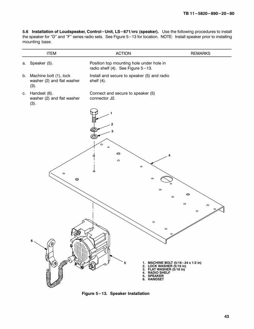
5.6 Installation of Loudspeaker, Control-Unit, LS-671/vrc (speaker). Use the following procedures to install
the speaker for �D" and �F" series radio sets. See Figure 5-13 for location. NOTE: Install speaker prior to installing
mounting base.
ITEM ACTION REMARKS
a. Speaker (5). Position top mounting hole under hole in
radio shelf (4). See Figure 5-13.
b. Machine bolt (1), lock Install and secure to speaker (5) and radiowasher (2) and flat washer shelf (4).
(3).
c. Handset (6). Connect and secure to speaker (5) washer (2) and flat washer connector J2.
(3).
3
2
1
5
4
1. MACHINE BOLT (5/16-24 x 1/2 in)2. LOCK WASHER (5/16 in)3. FLAT WASHER (5/16 in)4. RADIO SHELF5. SPEAKER6. HANDSET
6
Figure 5-13. Speaker Installation

TB 11-5820-890-20-80
44
5.7 Post-Installation and Checkout. After equipment is installed and cables are connected, perform thefollowing steps.
ITEM ACTION REMARKS
a. Equipment. Check for secure mounting. Checkfor loose parts, connectors and
mounting hardware.
b. Cables. Check for proper installation andconnection of cables. See Figure
5-14 for cable connections. Unused
cables should be stowed in appropri-ate place inside the vehicle.
c. Loop clamps. Check that all have been properly
installed and tightened.
d. Protective covers. Insure that all installed cables are
covered when not in use or con-
nected.
e. Radio issued with vehicle. Install and connect cables. See
TM 11-5820-890-20-1 or
TM 11-5820-890-20-4 forinstallation and Operational (OP)
Check instructions.
f. MK line replaceable units. See TM 11-5820-890-20P for RepairParts and Special Tools List (RPSTL)
information.

TB 11-5820-890-20-80
45/(46 blank)
5.7 Post-Installation and Checkout. Continued
CX-13302/VRC P2 Mounting base J1 T1: Red (+) Batteries (+) Lug (13 FT, 0 IN) T2: Black (-) (-) Lug
CG-3855/VRC P1 Antenna base J1 P2 RF amplifier J1 (15 FT, 0 IN) or radio
Handset cable Handset Amplifier�adapter J3
Speaker cable LS-454/U Amplifier�adapter J6 speaker
CX-13292/VRC P2 Mounting Base J3 P1 Speaker J1 (6 FT, O IN)
CABLE ASSEMBLY
FROM TO
CABLECONN.
UNITUNIT CONN.
CABLECONN.
UNIT UNIT CONN.
Figure 5-14. Cable Diagram: For AN/VRC-87/88/90 Series
T1 (+)
T2 (-)
(TO BATTERIES)
P1
J1
P2
P2
HANDSETH-250/U
ANTENNA
RF CABLE,CG-3855/VRC
(15 FT, 0 IN)
J1
P2
MOUNTING BASEJ2J4J3J1
RADIO
RFAMPLI- FIER
POWER CABLE, CX-13302/VRC (13 FT, 0 IN)
LS-454/USPEAKER
(FOR AN/VRC-90 Series)
J6
J3
AMPLIFIERADAPTER
J1
J2*SPEAKER
*NOT SUPPLIED IN THIS MK
*SPEAKER CABLECX-13292/VRC
(6 FT, 0 in)
P2

TB 11-5820-890-20-80
A-1/(A-2 blank)
APPENDIX A
REFERENCES
AMDF Army Master Data File (Microfiche)
AR 710-2 Supply Policy Below the Wholesale Level as Contained in Unit Supply UPDATE
AR 725-50 Requisitioning, Receipt and Issuing System in UPDATE
DA Pam 25-30 Consolidated Index of Army Publications (Microfiche)
DA Pam 710-2-1 Using Unit Supply System Manual Procedures as Contained in Unit Supply UPDATE
SB 11-131-2 Vehicular Radio Sets and Authorized Installations (SINCGARS)
TM 11-5820-890-10-1 Operator's Manual (ICOM Radio Sets)
TM 11-5820-890-10-3 Operator's Manual (Non-ICOM Radio Sets)
TM 11-5820-890-20-1 Unit Maintenance Manual (ICOM Radio Sets)
TM 11-5820-890-20-2 Unit Maintenance Manual (Non-ICOM Radio Sets)
TM 11-5820-890-20P Repair Parts and Special Tools List

By Order of the Secretary of the Army: ERIC K. SHINSEKI General, United States Army Official: Chief of Staff
9916737 DISTRIBUTION: To be distributed in accordance with the initial distribution number (IDN) 369611 requirements for TB 11-5820-890-20-80.

.
.
.
.
.
.
.
.
.
.
.l
.
.
.
.
.
.
.
.
.
.
.
.
.
.
.
.
.
.
.
.
.
.
.
4:
ci
a
E
i
iz
s
%
E
.
.
.
.
.
.
.
.
.
.
.
.
.
.
.
.
.
.
.
.
.
.
.
.
.
.
.
.
.
.
.
.
.
.
.
.
.
.
.
.
RECOMMENDED CHANGES TO EQUIPMENT TECHNICAL PUBLICATIONS
SOMETHING WRONG WITH THIS PUBLICATION
THEN . JOT DOKW THE INFOABOUT IT ON THIS FORM.CAREFULLY TEAR IT OmFOLD IT AND DROP IT IN THEMML.
t
FROM:i!iPo~~OKJ; UNITS COMPLETE ADDRESS)
Stateside Army DepotA-I-I-N: AMSTA-USStateside, N.J. 07703-5007
DATE SENT
10 July 1975
PUBLICATION NUMBER
TM 11-5840-340-12 I PUBLICATION DATE
I
PUBLICATION TITLE
23 Jan 74 Radar Set AN/PRC-76
BE EXACT PIN-POINT WHERE IT IS
PAGE PARANO GRAPH
2-25 2-28
3-10 3-3
5-6 5-8
FIGURENO
FO-3
TABLENO
3-1
TIN THIS SPACE TELL WHAT IS WRONGAND WHAT SHOULD BE DONE ABOUT IT:
Recommend that the installation antenna alignmentprocedure be changed throughout to specify a 20 IFFantenna lag rather than 10.
REASON: Experience has shown that with only a 10 lag,
excess of 25 knots, and has a tendand decelerate as it hunts, causing
13 2 dB” to 0 3 dB”.
ocedure for the TRANS POWER
to read, OReplace cover plate removed in
: To replace the cover plate.
)tone C 3. On 51-2, change Cl+24 VDC” to Cl+5 VDC”.
REASON: This is the output line of the 5 VDC power supply.+24 VDC is the input voltage.
PRINTED NAME, GRADE OR TITLE AND TELEPHONE NUMBER
SSG I. M. DeSpiritof 999-1776
DA ,%%2028-2 PREVIOUS EDITIONSARE OBSOLETE
P.S. - IF YOUR OUTFIT WANTS TO I&W ABOUT&JRRECOMMENDATION MAKE A CARBON COPY OF THISAND GIVE IT TO YOUR HEADQUARTERS.

.
.
.
.
.
.
.
*
.
.
.
.
.
.
.
.
.
.
.
.
.
.
.
.
.
.
.
.
.
.
.
.
.
.
.
E
5
E
E
B
2
2
2
2
.
.
.
.
.
.
.
.
.
.
.
.
.
.
s
.
.
.
.
.
.
.
.
.
.
.
.
.
.
.
.
.
.
.
.
I‘UBLICATION NUMBER
BE EXACT PIN-POwI- WHERE IT IS II[N THIS SPACE TELL WHAT IS WRONGUVD WHAT SHOULD BE DONE ABOUT IT:
PAGE FIGURE TABLENO NO NO
PRINTED NAME, GRADE OR TITLE AND TELEPHONE NUMBER SIGN HERE
.9 D A 1%%2028-2.
RECOMMENDED CHANGES TO EQUIPMENT TECHNICAL PUBLICATIONS
THEN... JOTDOKVTHEINFOABOUT IT ON THIS FORM.CAREFULLY TEAR IT OUT.FOLD IT AND DROP IT IN THE.IlTT
SOMETHING WRONG WITH THIS PUBLICATION
FROM: (PRINT YOUR UNIT’S COMPLETE ADDRESS)
DATE SENT
I PUBLICATION DATE
I
PUBLICATION TITLE
PREVIOUS EDITIONSARE OBSOLETE
P.S. -IF YOUR OUTFIT WANTS TO KNOW ABOUT YOURRECOMMENDATION MAKE A CARBON COPY OF THISAND GIVE IT TO YOUR HEADQUARTERS.
.
.

REVERSE OF DA FORM 2028-2
.
.
.
.
.
.
.
.
.
.
.
.
.
.
.
.
.
.
.
.
.
.
.
.
.
.
.
.
.
.
.
.
.
.
.
.
.
.
.
.
FOLD BACK-----------------------------------------------------------------------------------------.
DEPARTMENT OF THE ARMY
OFFICIAL BUSINESS
CommanderU.S. Army Communications-Electronics Command
and Fort MonmouthATTN: AMSEL-LC-LEO-D-CS-CFOFort Monmouth, New Jersey 07703-5000
.
.
.
.
.
.
.
.
.
.
.
.
.
.
.
.
m
.
.
.
.
.
.
.
.
.
.
.
.
.
.

THE METRIC SYSTEM AND EQUIVALENTS

PIN: 072173-000


![[PPT] Familiarization... · Web view... TM 11-5820-890-10-8 TM 11-5820-890-10-2 METHODS OF COMMUNICATION VISUAL SIGNALS (Hand signals, Semaphore) SOUND SIGNALS (Speaking from one](https://img.pdfslide.us/doc/110x75/5b4cba5b7f8b9ad1338ba810/ppt-familiarization-web-view-tm-11-5820-890-10-8-tm-11-5820-890-10-2.jpg)