Embed Size (px)
Citation preview
" c 01744 3
fleas*/pmn PITITICATTONS CTMACT7
(Lri^s--cTioiN)DEPARTMENT OFMINERALS AND ENERGY
•
BUREAU OF MINERAL RESOURCES,GEOLOGY AND GEOPHYSICS
1 975/141
7. --",,A■ I, Po
,^tit tor-L-•;:; 1 6 JUL, 1976^.
MODIFICATION OF THE PRESS■EWING LONCPERIOD
SEISMOMETER TO COMPENSATE FOR THE EFFECTS
OF TEMPERATURE CHANCES
by
P.J. HILLMAN
The information contained in this report has been obtained by the Department of Minerals and Energy
as part of the policy of the Australian Government to assist in the exploration and development ofmineral resources. It may not be published in any form or used in a company prospectus or statementwithout the permission in writing of the Director. Bureau of Mineral Resources, Geology and Geophysics.
BMRRecord
1975/141c.3
1975/141
MODIFICATION OF THE PRESS-EWING LONG-PERIOD
SEISMCVETER TO COMPENSATE FOR THE EFFECTS
OF TEMPT:NATURE CHANGES
by
P.J. HILLMAN
CONTENTS
Summary
1. INTRODUCTIOV
2. OUTLINE OF OVERALL SERVO—SYSTEM
3. DETAILED DESCRIPTION OF SYSTEM
Seismometer drift compensator
Assembly
Initial adjustments and tests
Adjustments in use
PLATES
Plate 1. Modified seismometer (external)
Plate 2. Modified seismometer (internal)
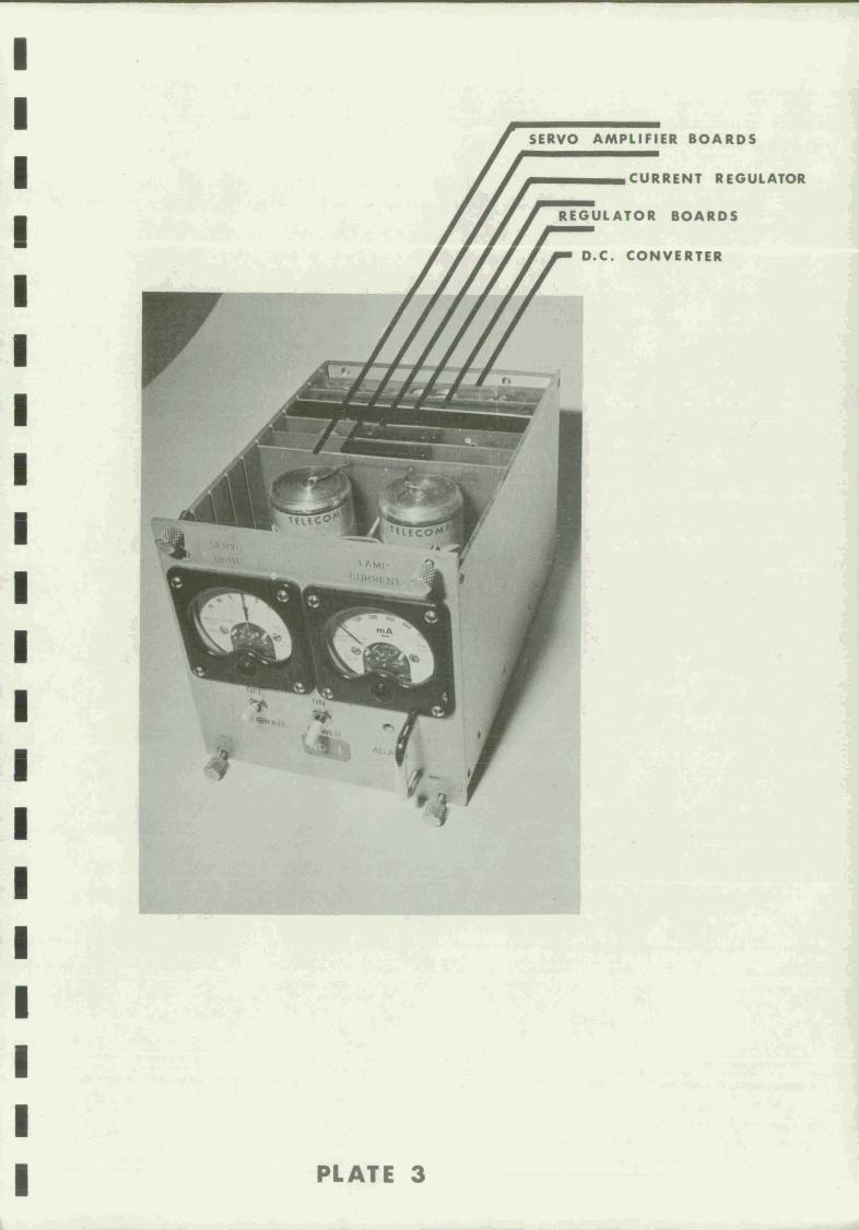
Plate 3. Seismometer drift compensator
FIGURES
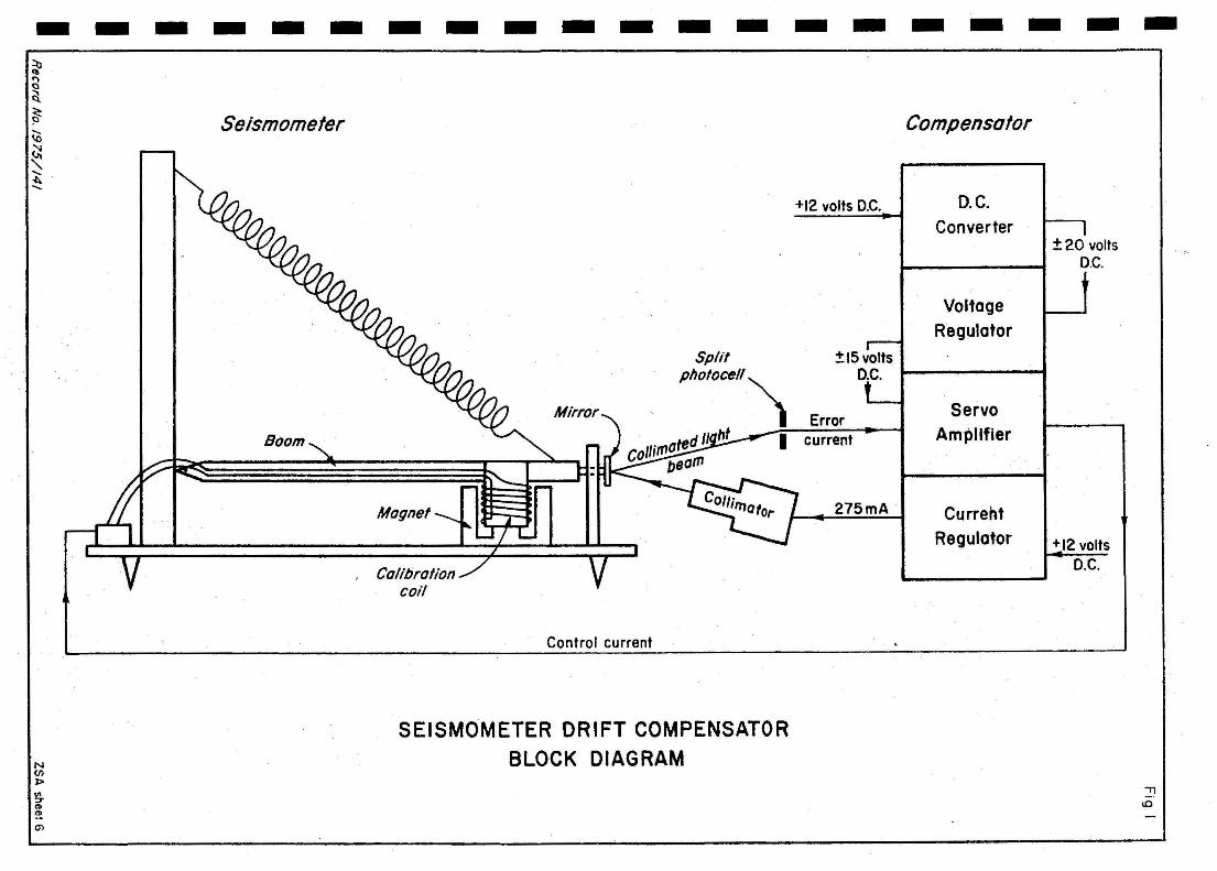
Fig. 1. Block diagram
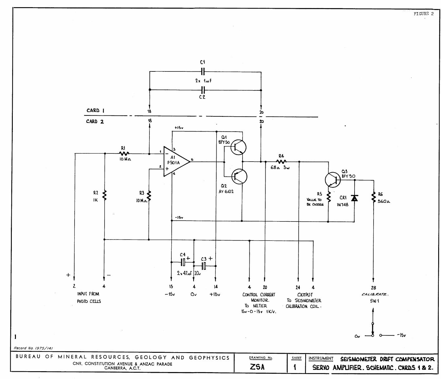
Fig. 2. Servo amplifier
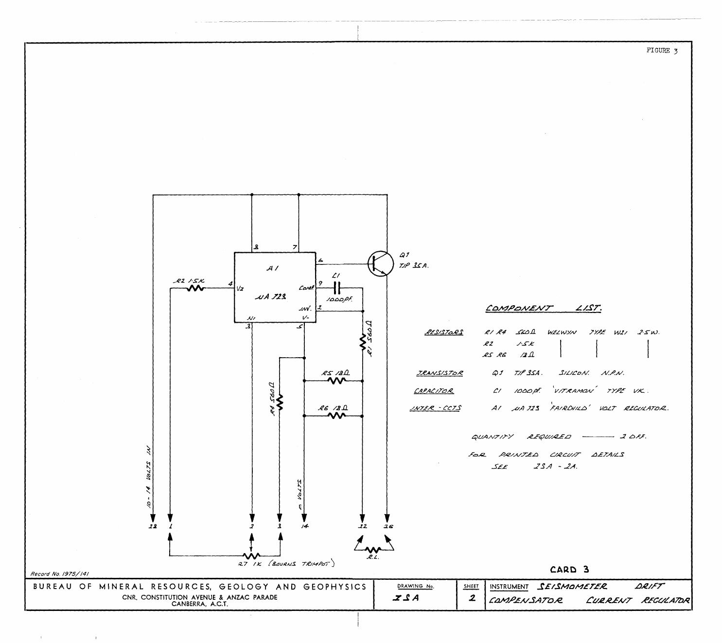
Fig. 3. Current regulator
Fig. 4. D.C. converter
Fig. 5. Regulator boardFig. 6. Chassis wiring
Fig. 7. Interconnecting cable
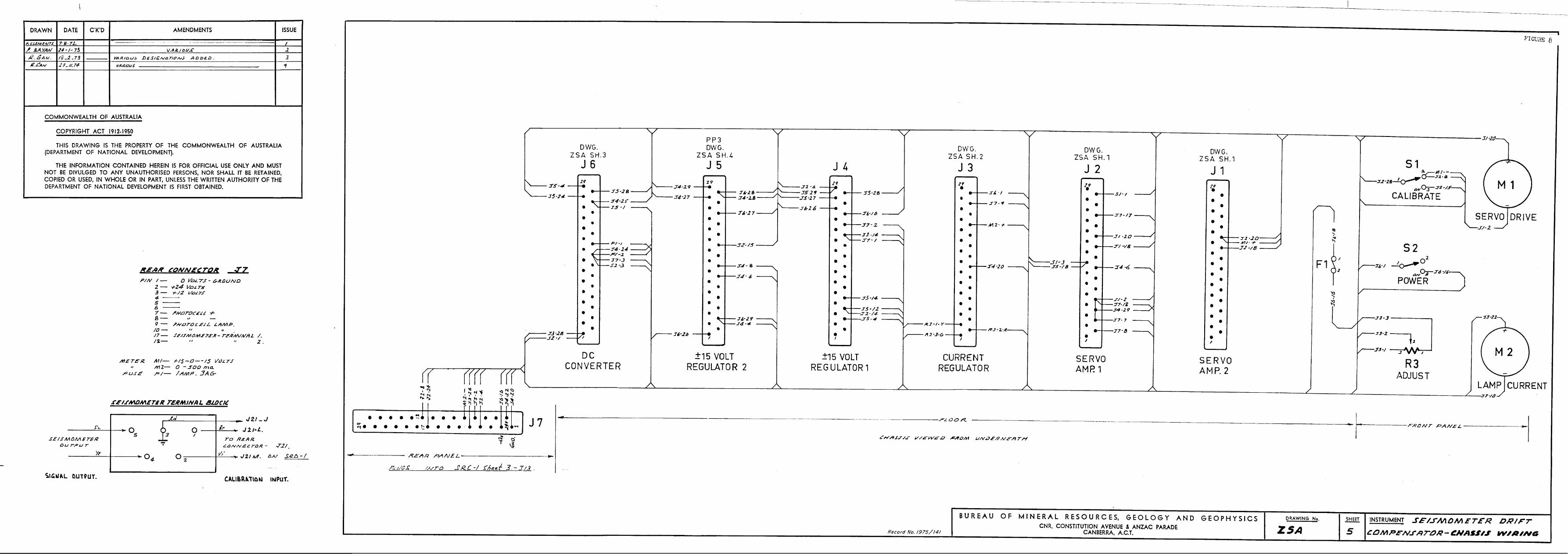
Fig. 8. Seismic recording system chassis wiring
Page
1
2
2
344
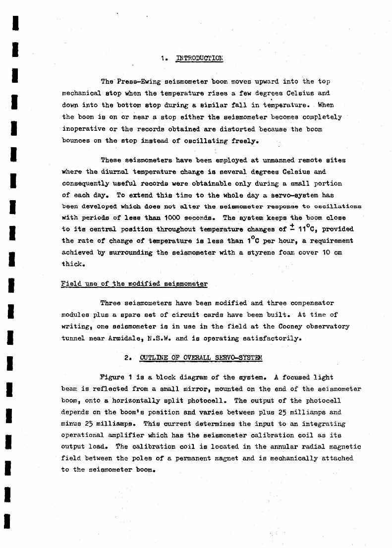
SIMINIARY
A system has been designed for use with a Press—Ewing vertical
long—period seismometer, Whioh will compensate for the mechanical drift
of the boom due to temperature changes of a few degrees Celsius. This
record describes the mechanical modifications made to the seismometer
and gives design details of the controlling servo—amplifier.
With this system the seismometer can be used, unattended, in
most field conditions in Australia and PG; without the system, use is
limited to an observatory vault or similar environment.
The record gives instructions for the assembly, adjustment,and testing of the system.
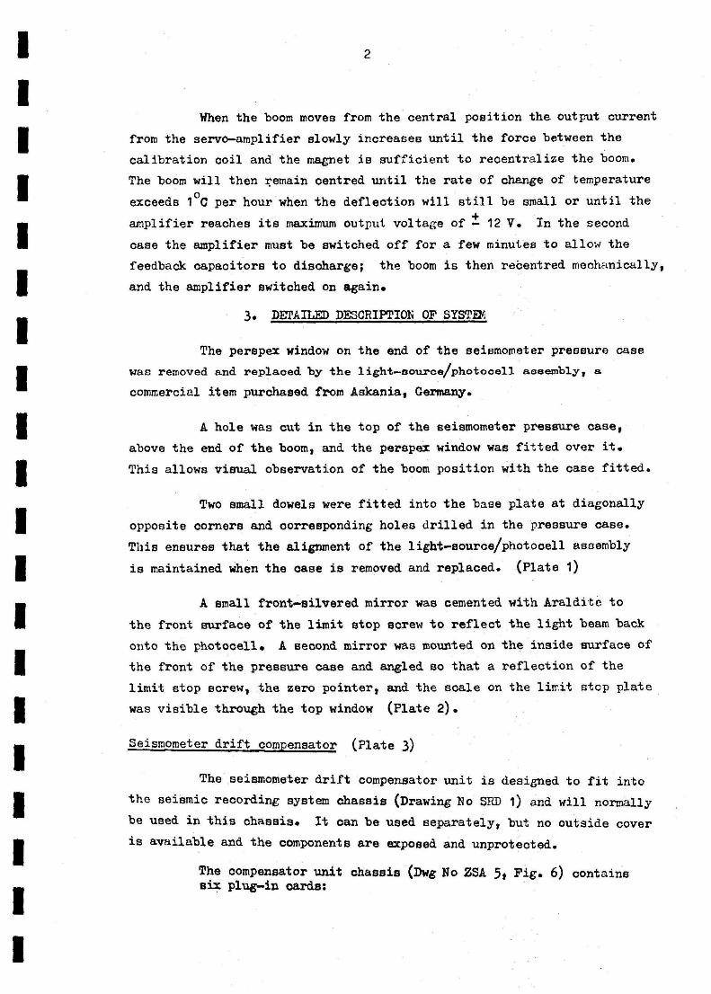
1. INTRODUCTIOL
The Press—Ewing seismometer boom moves upward into the top
mechanical stop when the temperature rises a few degrees Celsius and
down into the bottom stop during a similar fall in temperature. When
the boom is on or near a stop either the seismometer becomes completely
inoperative or the records obtained are distorted because the boom
bounces on the stop instead of oscillating freely.
These seismometers have been employed at unmanned remote sites
where the diurnal temperature change is several degrees Celsius and
consequently useful records were obtainable only during a small portion
of each day. To extend this time to the whole day a servo—system has
been developed which does not alter the seismometer response to oscillations
with periods of less than 1000 seconds. The system keeps the boom closeoto its central position throughout temperature changes of — 11 C, provided
the rate of change of temperature is less than 1 °C per hour, a requirementachieved by surrounding the seismometer with a styrene foam cover 10 cm
thick.
Field use of the modified seismometer
Three seismometers have been modified and three compensator
modules plus a spare set of circuit cards have been built. At time of
writing, one seismometer is in use in the field at the Cooney observatory
tunnel near Armidale, V.S.W. and is operating satisfactorily.
2. OUTLINE OF OVERALL MVO—SYSTEM
Figure 1 is a block diagram of the system. A focused light
beam is reflected from a small mirror, mounted on the end of the seismometer
boom, onto a horizontally split photocell. The output of the photocell
depends on the boom's position and varies between plus 25 milliamps and
minus 25 milliamps. This current determines the input to an integrating
operational amplifier which has the seismometer calibration coil as its
output load. The calibration coil is located in the annular radial magnetic
field between the poles of a permanent magnet and is mechanically attached
to the seismometer boom.
2
When the boom moves from the central position the output current
from the servo—amplifier slowly increases until the force between the
calibration coil and the magnet is sufficient to recentralize the boom.
The boom will then remain centred until the rate of change of temperature
exceeds 1 °C per hour when the deflection will still be small or until theamplifier reaches its maximum output voltage of ± 12 V. In the second
case the amplifier must be switched off for a few minutes to allow the
feedback capacitors to disoharge; the boom is then rebentred mechanically,
and the amplifier switched on again.
3. DETAILED DESCRIPTION OF SYSTEM
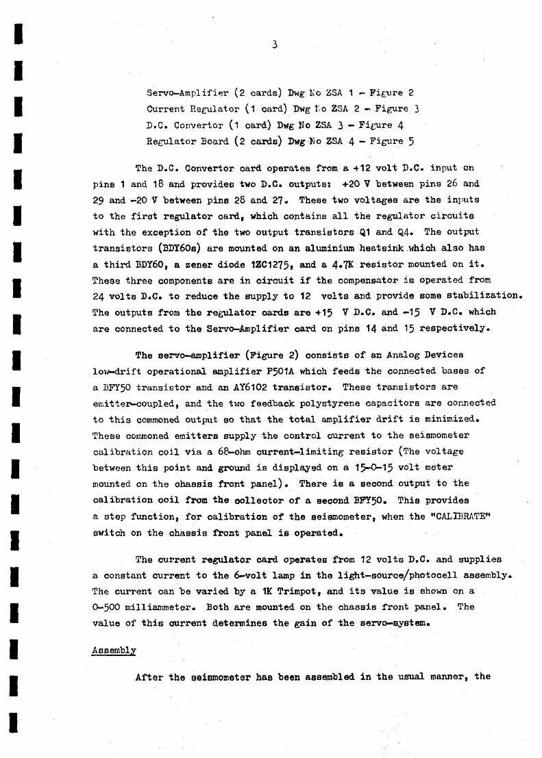
The perspex window on the end of the seismometer pressure case
was removed and replaced by the light—source/photocell assembly, a
commercial item purchased from Askania, Germany.
A hole was cut in the top of the seismometer pressure case,
above the end of the boom, and the perspex window was fitted over it.
This allows visual observation of the boom position with the case fitted.
Two small dowels were fitted into the base plate at diagonally
opposite corners and corresponding holes drilled in the pressure case.
This ensures that the alignment of the light—source/photocell assembly
is maintained when the case is removed and replaced. (Plate 1)
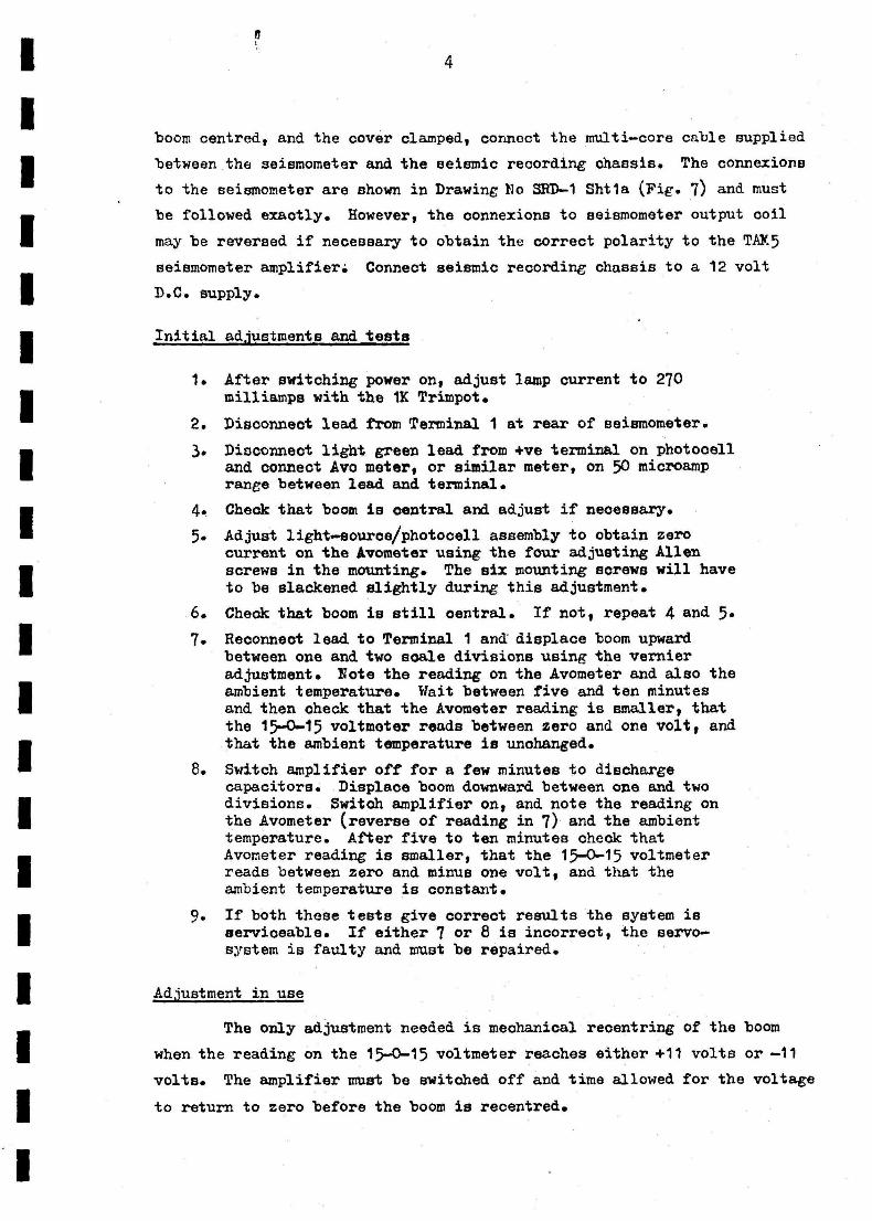
A small front—silvered mirror was cemented with Araldite to
the front surface of the limit stop screw to reflect the light beam back
onto the photocell. A second mirror was mounted on the inside surface of
the front of the pressure case and angled so that a reflection of the
limit stop screw, the zero pointer, and the scale on the limit stop plate
was visible through the top window (Plate 2).
Seismometer drift compensator (Plate 3)
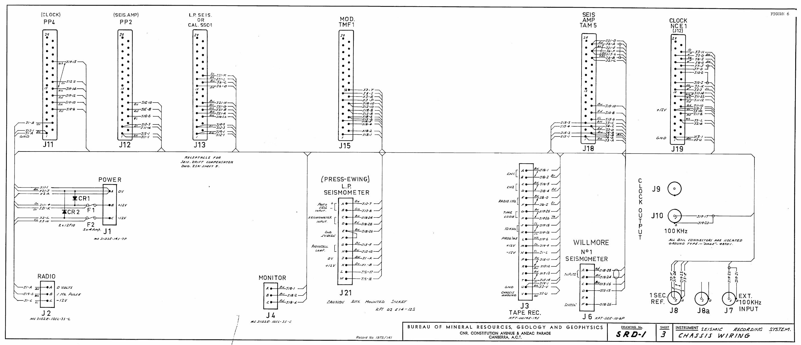
The seismometer drift compensator unit is designed to fit into
the seismic recording system Chassis (Drawing No SRI) 1) and will normally
be used in this chassis. It can be used separately, but no outside cover
is available and the components are exposed and unprotected.
The compensator unit chassis (Dwg No ZSA 5 Fig. 6) containssix plug—in cards:
Servo—Amplifier (2 cards) Dwg No ZSA 1 — Figure 2
Current Regulator (1 card) Dwg ro ZSA 2 — Figure 3
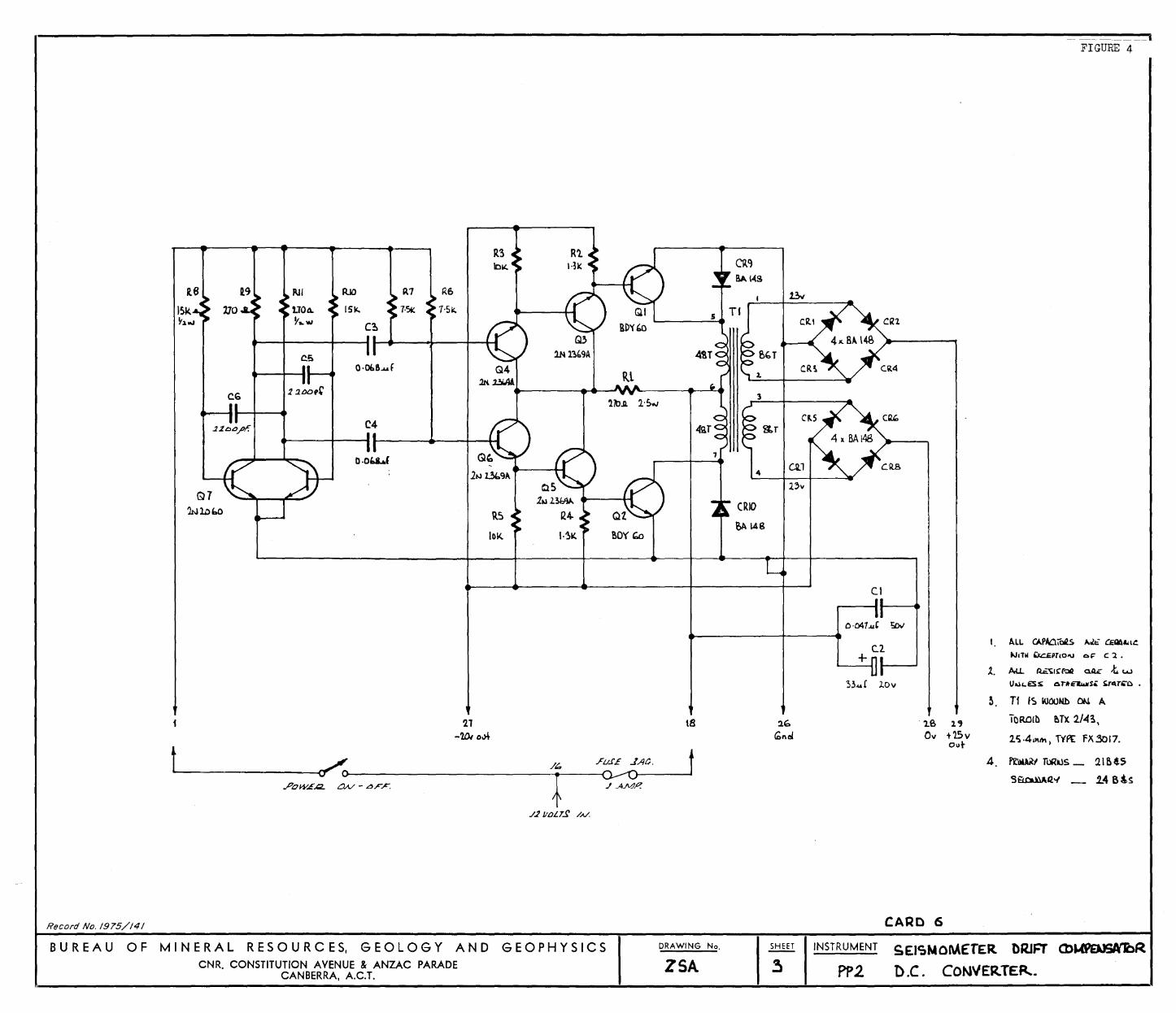
D.C. Convertor (1 card) Dwg No ZSA 3 - Figure 4
Regulator Board (2 cards) Dwg.No ZSA 4 - Figure 5
The D.C. Convertor card operates from a +12 volt D.C. input on
pins 1 and 18 and provides two D.C. outputs: +20 V between pins 26 and
29 and —20 V between pins 28 and 27. These two voltages are the inputs
to the first regulator card, which contains all the regulator circuits
with the exception of the two output transistors Q1 and Q4. The output
transistors (BDY60s) are mounted on an aluminium heatsink.which also has
a third BDY60, a zener diode 1ZC1275, and a 4.7K resistor mounted on it.
These three components are in circuit if the compensator is operated from
24 volts D.C. to reduce the supply to 12 volts and provide some stabilization.
The outputs from the regulator Garde are +15 V D.C. and —15 V D.C. which
are connected to the Servo—Amplifier card on pins 14 and 15 respectively.
The servo—amplifier (Figure 2) consists of an Analog Devices
low—drift operational amplifier P501A which feeds the connected bases of
a BFY50 transistor and an AY6102 transistor. These transistors are
emitter—coupled, and the two feedback polystyrene capacitors are connected
to this commoned output so that the total amplifier drift is minimized.
These commoned emitters supply the control current to the seismometer
calibration coil via a 68—ohm current—limiting resistor (The voltage
between this point and ground is displayed on a 15-0-15 volt meter
mounted on the ohassis front panel). There is a second output to the
calibration coil from the collector of a second BFY50. This provides
a step function, for calibration of the seismometer, when the "CALIBRATE"
switch on the chassis front panel is operated.
The current regulator card operates from 12 volts D.C. and supplies
a constant current to the 6—volt lamp in the light—source/photocell assembly.
The current can be varied by a IK Trimpot, and its value is shown on a
0-500 milliammeter. Both are mounted on the chassis front panel. The
value of this aurrent determines the gain of the servo—system.
Assembly
After the seismometer has been assembled in the usual manner, the
4
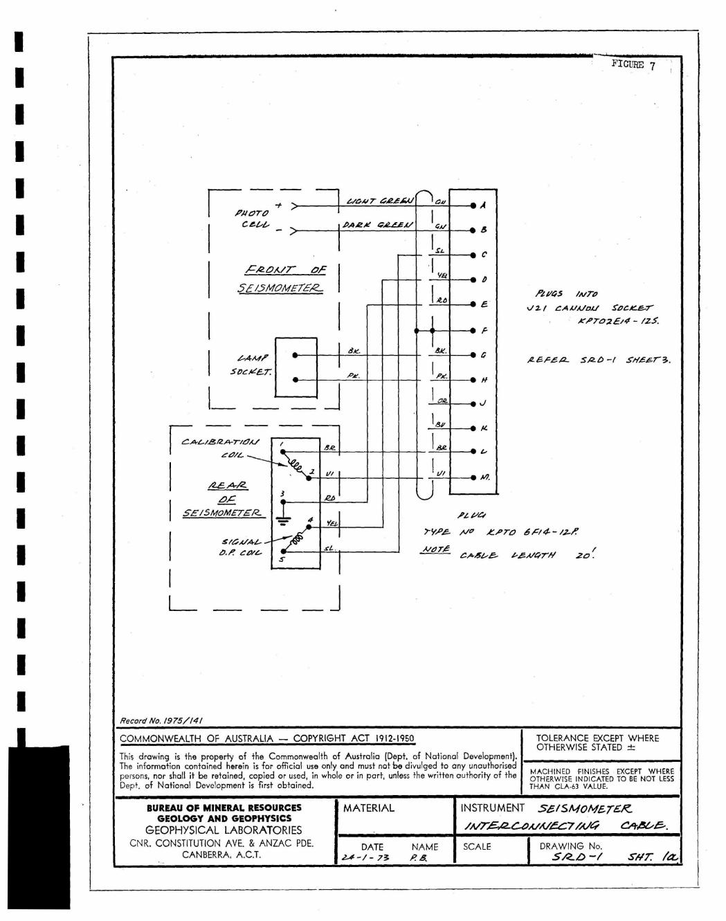
boom centred, and the cover clamped, connect the multi—core cable supplied
between the seismometer and the seismic recording chassis. The connexions
to the seismometer are shown in Drawing Vo 3RD-1 Shtla (Fig. 7) and mustbe followed exactly. However, the connexions to seismometer output coil
may be reversed if necessary to obtain the correct polarity to the TAK5
seismometer amplifier: Connect seismic recording chassis to a 12 voltD.C. supply.
Initial adlystments and tests
1. After switching power on, adjust lamp current to 270milliamps with the 1K Trimpot.
2. Disconnect lead from Terminal 1 at rear of seismometer.
3. Disconnect light green lead from +ve terminal on photocelland connect Ave meter, or similar meter, on 50 microamprange between lead and terminal.
4. Cheek that boom is central and adjust if necessary.
5. Adjust light—source/photocell assembly to obtain zerocurrent on the Avometer using the four adjusting Allenscrews in the mounting. The six mounting screws will haveto be slackened slightly during this adjustment.
6. Cheek that boom is still oentral. If not, repeat 4 and 5.
7. Reconnect lead to Terminal 1 and displace boom upwardbetween one and two scale divisions using the vernieradjustment. Note the reading on the Avometer and also theambient temperature. Wait between five and ten minutesand then cheek that the Avometer reading is smaller, thatthe 15-0-15 voltmeter reads between zero and one volt, andthat the ambient temperature is unchanged.
8. Switch amplifier off for a few minutes to dischargecapacitors. Displace boom downward between one and twodivisions. Switch amplifier on, and note the reading onthe Avometer (reverse of reading in 7) and the ambienttemperature. After five to ten minutes check thatAvometer reading is smaller, that the 15-0-15 voltmeterreads between zero and minus one volt, and that theambient temperature is constant.
9. If both these tests give correct results the system isserviceable. If either 7 or 8 is incorrect, the servo—system is faulty and must be repaired.
Adjustment in use
The only adjustment needed is mechanical recentring of the boom
when the reading on the 15-0-15 voltmeter reaches either +11 volts or —11
volts. The amplifier must be switched off and time allowed for the voltage
to return to zero before the boom is recentred.
. l ~ m t m c r llTNlT PUT
WBrnl)rlAL
PLATE 1
/-, L I M I T STOP PLATE A N D SCALE
PLATE 2
f SERVO AMPLIFIER BOARD 7
//I--.--. CURRENT REO
TOR BOARDS
CONVERTER
,
D.C.Converter
VoltageRegulator
ServoAmplifier
CurrehtRegulator
,
±15 voltsD.C.
Splitphotocell
+12 volts D.C. ,„
Mirror
Boom
Magnet
Calibrationcoil
Control current
± 20 voltsD.C.
+12 voltsD.C.
1=11 NM NM ME MI MI I= NMI IMMI NM 1=11 INN NE 1=1 =I =I 1=1 11=1 MI NM
cb
Seismometer^
Compensatorkr)
SEISMOMETER DRIFT COMPENSATORBLOCK DIAGRAM
----- - - - ------ -- - ---------
FIGURE 3
7
4~2. /·S.K........__---...."V\o......r-----f V.z
AIL/
CDId.l. t-9_ ....:; ----.
/aaa.,pr.
" ..
Ca~PO.N.E.A/r L/-sr.
'::t'<l ..RE.f/.sTa..;e.s R/ ..R# .s£L>..fl. WELWY.N .7Y/L W.l/ .2-SJAJ.
~~ \(J~YJ RZ /·I.£ I I I...~ :\
~ .RS ~s /~.fL
J-RAN...S'/.S To..R t;)f 7://oSSA. ..J/L/CoN. /\I..P.'.II/.
I .,.CA.I'AL'/TCJ£ C/ /CJ6CJP V/T~AMav 7Y"pL" VA:::..
I
/h'7E~ ... C'CTS A/ ",oA .7.2j rA/.RL'H/LL:> ' J/CJLT RL~/LATO"tZ. .
RS /1J1l.A.AAYV
.RS /3.fl.AAa.
../HV. ~.2.~ ---.
v-
Record No. 1975/141
~
~
"~~
'""- 'i
I ~
~ Q
"1. 'r 'r u
.2~ 1 .2 j /4-
t t rV\I'R..7 IX: [/laIM!,v-S 7£/M,PO/)
" ,
~.R.L.
.5£.£ .z.sA - ..LA.
CARD 3
BUR EA U 0 F MIN ERA L RE5 0 U RC E5, G E0 LOG Y AND G E0 PH Y SIC SCNR. CONSTITUTION AVENUE & ANZAC PARADE
CANBERRA, A.C.T.
DRAWING No.
.z.1ASHEET INSTRUMENT ..r£I.sMOM£TE/l. LJAl//T
2. C.aM.PLN..sAro~ CU.,2/lE"I,/T RECC/LA7lJ..I<
-- --.. - IFIGURE 4
16 i9 R11 ItJO R7 P,6 13-1
15k 1]0 tlot\. IS!'. 1-~ 1·51:.~1'" ~... ""
C~
Co!:)
Q·0I.8 .... fRl
CG 22bD,r'llbJl. l'S""
C4 CP.5.2200fJr. ~r
O.Oba...( cu.ll'v
Q7~l.obO
(RIO
~ \.4810K. ~OYWl
Cl
t ~ fuSE ..lAC. t----rr O----------T-O--O~
"pOW.,£..Q. a.v - LJF~ t ./ AMP.'
'2.1-Wi 0'>+
\8
C.2+
33.... £ 1o".2..
~.
l.B l'0" t'15v
Ollt
4
ALL. CAPAai'oQ,S I.J.ti: CEIl6"I~
""'ITIl ~pr(o"\J or: C '2 •
ArU. ~~I~('OIII a.lL;: -t. l.I..I
I)UL.CSS aTItE'lw/S': S;r",r_c> •
Tf I~ I000Nb 0tJ. A
TORD!!) e.Tx 214~,
lli.4I)11t\, WI'[ FX3017.
l'£.~ TuRllS _ 21Bt5
S~Q"" _ 1.4 6&~
./.2 /lbLT..f /.1./.
Record No. /975//4/ CARD CS
BUR EA U 0 F MIN ERA L R E$ 0 U RC E$, G E0 LOG Y AND G E0 PH Y $ I C $
CNR. CONSTITUTION AVENUE & ANZAC PARADECANBERRA, A.C.T.
DRAWING No.
ZSASHEET INSTRUMENT SEI~NOME'rER DRIFT (J)~R
3 P?2 D.C. CON'IERTE~.
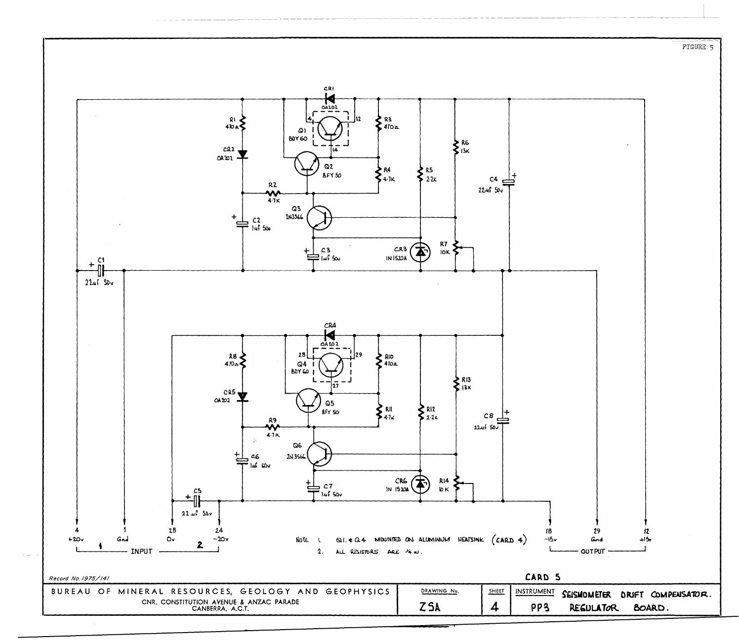
FIGURE 5
CoR I
+C4
It..llf ~"
R710K
R.52·2t:
c..R3
IN 151DA
IB410A
R44·1K.
Q2&F'( 50
OAlot---- ....4
1I \'2I
I_-1
14
QI8OV60
Rl
4'1K
+
c.Q.l
0A'101
+ ctL-----------..------...--------~-___4~_+_-____t_.-..------___,
21.uf SO"
c';)
+
CR5OA. 'lD2
+
QAtDl18 r - - - --I 29
Q4 I IMY(;,D I I
L J17
RIO4104.
RII4·7.<
CkbIN 152DA
RI21·21:,
RI3111<
RI4 ~--..
10K
+
'8-\~v
'------ INPUT
113
0"2.
2.4-'1Dv t..lo\E.. to &1. ot: Q4 MooN'I"ED 0\1 ALlIMINlJJ.A J.,lfATSIl'ik:, ('AltO 4)
1. ~Ll.. 'k'""S.ISltlRS AG.£ >+ IAJ •
29 ItGond 4-1~
L.-__ OUTPUT ---I'
Record No. /975//4/ CARD 5BUR EA U 0 F MIN ERA L RE5 0 U R C E5, G E0 LOG Y AND G E0 PH Y 5 I C 5
CNR. CONSTITUTION AVENUE & ANZAC PARADECANBERRA, AC.T.
DRAWING No.
ZSl
SHEET
4INSTRUMENT
pp~
~g~"'ouETER DRJFT COMPBlSA1'OR..
REbUUToR &lARD.
FON OTO
1./a417- GA24.4(/ /—)
.0.0*.A 2 X CA/
• A
,C-A2DA/7-
5E/5matiE1ER_
the./2- a P.6.47- 5,240 -I SH.647- 3.
519cAd6.7:
^• At
4,[--
LIIIA/
Go,C
/SMOMETEIL
4-stGA/az-
co/e.-
Record No. /975/141
TOLERANCE EXCEPT WHEREOTHERWISE STATED :L.-
COMMONWEALTH OF AUSTRALIA — COPYRIGHT ACT 1912-1950
This drawing is the property of the Commonwealth of Australia (Dept. of National Development).The information contained herein is for official use only and must not be divulged to any unauthorisedpersons, nor shall it be retained, copied or used, in whole or in part, unless the written authority of theDept, of National Development is first obtained.
MACHINED FINISHES EXCEPT WHEREOTHERWISE INDICATED TO BE NOT LESSTHAN CLA-b3 VALUE.
NAME^SCALE^DRAWING No.S/2.41 INSTRUMENT se/SMOMErgg-
hvr.E.,a_c_zuhv.e.c7 //c/ c,i-oese.- .BUREAU OF MINERAL RESOURCES
GEOLOGY AND GEOPHYSICSGEOPHYSICAL LABORATORIES
CNR. CONSTITUTION! AVE. & ANZAC PDE.CANBERRA, A.C.T.
I MATERIAL
DATE2-1 - / - 73 fr? B,
I
^•
^• ‘-/
FIGURE 7
1711/4-5 /A/Tao
%/ 2- 1 CAVA/1W SOC.e.E.-7"
K.0702E/4 - /25.
At 1/4
T. 5e.0 -^ ,e,oro 6C/4-- 4z-P
2C.