Embed Size (px)
DESCRIPTION
.
Citation preview
uBro Soultion Description Contents
Issue 03 (2008-04-30) Huawei Proprietary and Confidential Copyright © Huawei Technologies Co., Ltd
i
Contents
1 Description of the uBro Solution............................................................................................1-1 1.1 Background ...................................................................................................................................................1-2 1.2 Huawei uBro Solution...................................................................................................................................1-2 1.3 Benefits .........................................................................................................................................................1-4
2 Solution Architecture ................................................................................................................2-1 2.1 Logic Architecture.........................................................................................................................................2-2 2.2 Major Equipment ..........................................................................................................................................2-2
2.2.1 AP ........................................................................................................................................................2-2 2.2.2 AG........................................................................................................................................................2-3 2.2.3 Clock Server.........................................................................................................................................2-3 2.2.4 AHR .....................................................................................................................................................2-4 2.2.5 AP Manager..........................................................................................................................................2-4 2.2.6 SeGW...................................................................................................................................................2-4 2.2.7 M2000..................................................................................................................................................2-4
2.3 Technical Features of the uBro System .........................................................................................................2-5 2.4 Interfaces.......................................................................................................................................................2-8
2.4.1 eIu Interface .........................................................................................................................................2-9 2.4.2 Ab/Ah Interface..................................................................................................................................2-11 2.4.3 Ae Interface........................................................................................................................................2-11 2.4.4 Hg Interface .......................................................................................................................................2-11 2.4.5 Ho Interface .......................................................................................................................................2-11 2.4.6 Ac Interface........................................................................................................................................2-11 2.4.7 Uu Interface .......................................................................................................................................2-11 2.4.8 Iu-CS Interface...................................................................................................................................2-11 2.4.9 Iu-PS Interface ...................................................................................................................................2-12
3 Networking Solution.................................................................................................................3-1 3.1 Service Networking.......................................................................................................................................3-2
3.1.1 Independent AG Networking Solution.................................................................................................3-2 3.1.2 eSGSN Networking Solution ...............................................................................................................3-3
3.2 Transmission Networking .............................................................................................................................3-4 3.2.1 xDSL Access Networking Solution......................................................................................................3-4

Contents uBro Soultion
Description
ii Huawei Proprietary and Confidential Copyright © Huawei Technologies Co., Ltd
Issue 03 (2008-04-30)
3.2.2 Ethernet Access Networking Solution .................................................................................................3-6
4 Security Solution........................................................................................................................4-1 4.1 Overview of the Authentication Security Solution........................................................................................4-2 4.2 Network equipment security .........................................................................................................................4-2 4.3 Network Security ..........................................................................................................................................4-2
4.3.1 Security Domain Partition....................................................................................................................4-2 4.3.2 Border Protection .................................................................................................................................4-3 4.3.3 Network Anti-Attack............................................................................................................................4-3 4.3.4 Network Access Authentication and Access Control ...........................................................................4-3 4.3.5 Transmission Security ..........................................................................................................................4-4
4.4 Operation and Maintenance Security ............................................................................................................4-5
5 Service Operation.......................................................................................................................5-1 5.1 Service Application .......................................................................................................................................5-2 5.2 Installation of the AP.....................................................................................................................................5-2 5.3 Interference Processing of the AP .................................................................................................................5-2 5.4 Movement of the AP .....................................................................................................................................5-3 5.5 Deregistration of the AP................................................................................................................................5-3 5.6 Upgrade of the AP.........................................................................................................................................5-3 5.7 Maintenance of the AP ..................................................................................................................................5-4
6 Operation and Maintenance ....................................................................................................6-1 6.1 O&M System ................................................................................................................................................6-2
6.1.1 Solution of Terminal Equipment Management ....................................................................................6-2 6.1.2 Solution of Central-Office Equipment Management ...........................................................................6-3
6.2 O&M System of the AP ................................................................................................................................6-3 6.2.1 AP Manager..........................................................................................................................................6-3 6.2.2 AP Manager Toolkit .............................................................................................................................6-4 6.2.3 AP LMT ...............................................................................................................................................6-5
6.3 O&M System of Central-Office Equipment..................................................................................................6-6 6.3.1 AG........................................................................................................................................................6-6 6.3.2 eSGSN .................................................................................................................................................6-7 6.3.3 Clock Server.........................................................................................................................................6-7 6.3.4 AHR .....................................................................................................................................................6-8 6.3.5 SeGW...................................................................................................................................................6-8
7 Reference Information ..............................................................................................................7-1 7.1 System Performance......................................................................................................................................7-2
7.1.1 AP ........................................................................................................................................................7-2 7.1.2 AG........................................................................................................................................................7-2 7.1.3 AP Manager..........................................................................................................................................7-3 7.1.4 AHR .....................................................................................................................................................7-3 7.1.5 Clock Server.........................................................................................................................................7-3
uBro Soultion Description Contents
Issue 03 (2008-04-30) Huawei Proprietary and Confidential Copyright © Huawei Technologies Co., Ltd
iii
7.1.6 SeGW...................................................................................................................................................7-4 7.2 Data Homing .................................................................................................................................................7-4 7.3 Referenced Standards and Protocols .............................................................................................................7-7

Figures uBro Soultion
Description
iv Huawei Proprietary and Confidential Copyright © Huawei Technologies Co., Ltd
Issue 03 (2008-04-30)
Figures
Figure 1-1 Networking application of the uBro solution....................................................................................1-3
Figure 2-1 Logic architecture of the uBro network ............................................................................................2-2
Figure 2-2 Interfaces in the uBro solution..........................................................................................................2-8
Figure 2-3 Interfaces in the uBro solution..........................................................................................................2-9
Figure 2-4 Protocol stack of the eIu interface ..................................................................................................2-10
Figure 3-1 Independent AG networking diagram...............................................................................................3-2
Figure 3-2 eSGSN networking diagram .............................................................................................................3-3
Figure 3-3 xDSL access topology.......................................................................................................................3-5
Figure 3-4 Ethernet access topology ..................................................................................................................3-6
Figure 6-1 Architecture of the O&M system......................................................................................................6-2

uBro Soultion Description Tables
Issue 03 (2008-04-30) Huawei Proprietary and Confidential Copyright © Huawei Technologies Co., Ltd
v
Tables
Table 7-1 AP system performance parameters....................................................................................................7-2
Table 7-2 AG system performance parameters ...................................................................................................7-2
Table 7-3 System performance parameters of AP Manager................................................................................7-3
Table 7-4 System performance parameters of AHR ...........................................................................................7-3
Table 7-5 System performance parameters of Clock Server...............................................................................7-3
Table 7-6 System performance parameters of Huawei SeGW............................................................................7-4
Table 7-7 Data stored on the AP .........................................................................................................................7-4
Table 7-8 Data stored on the AHR......................................................................................................................7-6
Table 7-9 Data stored on the AP Manager ..........................................................................................................7-7

1 Description of the uBro Solution uBro Soultion
Description
1-0 Huawei Proprietary and Confidential Copyright © Huawei Technologies Co., Ltd
Issue 03 (2008-04-30)
1 Description of the uBro Solution
About This Chapter
The following table lists the contents of this chapter.
Section Describes
1.1 Background The application background of Huawei uBro solution.
1.2 Huawei uBro Solution The networking application of Huawei uBro solution.
1.3 Benefits The benefits of the uBro solution for telecom operators and users.

uBro Soultion Description 1 Description of the uBro Solution
Issue 03 (2008-04-30) Huawei Proprietary and Confidential Copyright © Huawei Technologies Co., Ltd
1-1
1.1 Background The indoor coverage of the Universal Mobile Telecommunications System (UMTS) signals has always been a difficult point that troubles users and telecom operators. The reasons are as follows:
The UMTS frequency is high, and its signals are always blocked by the obstacles, which causes that users fail to use the UMTS signals in small and medium enterprises (SMEs), small offices and home offices (SOHOs), and houses
The coverage of indoor signals has different features from the coverage of outdoor signals. Outdoor signals cover a large area. This is called plane coverage. The indoor UMTS are of small capacity and of micro areas. Therefore, the wireless coverage of indoor signals requires point coverage. The solution of macro network cannot solve the indoor coverage problem. Therefore, a better indoor coverage solution is required.
With wide use of the UMTS wireless network, indoor users require the wireless data service of high speed, convenience, and low cost. Though (HSDPA) and (HSUPA) are applied gradually, these service bandwidth resources are shared by many users because there are many users in the macro network. Therefore, the service bandwidth allocated to each user is low and cannot satisfy the requirements of high speed services.
To solve the problem of the coverage of indoor signals, telecom operators have to consider the cost of purchasing equipment, installing and maintaining the equipment. In a word, telecom operators need a solution of low cost but of high bandwidth.
Therefore, Huawei Technologies Co., Ltd. (hereafter referred to as Huawei) provides the uBro solution, which effectively solves the problem of the coverage of UMTS indoor signals.
1.2 Huawei uBro Solution Figure 1-1shows the networking application of Huawei uBro solution.

1 Description of the uBro Solution uBro Soultion
Description
1-2 Huawei Proprietary and Confidential Copyright © Huawei Technologies Co., Ltd
Issue 03 (2008-04-30)
Figure 1-1 Networking application of the uBro solution
SeGW
AG
AHR
AP Manager
M2000
IP Network
UMTS Core Network
Clock Server
HOME Zone
AP HGW UE
SME Zone
AP AP
UE UE
Office LAN
uBro Core NetworkPublic NetworkUser Access Network
IP Network
NodeB RNC
AP access point AG access gateway AP Manager AP management maintenance
center AHR AP home register
SeGW security gateway M2000 EMS server Clock Server clock server UE user equipment HGW home gateway NodeB UMTS base station RNC radio network controller
According to locations and functions, the uBro network is divided into three parts:
User access network The uBro user access network complete the access function for the uBro network services. The AP, as terminal equipment, is installed in the home, SME or SOHO, and then connected to the public network through the enterprise Ethernet or a home gateway such as ADSL MODEM. By performing the functions of wireless modulation and demodulation, wireless resource management, and power control, the AP can be used to implement the UMTS wireless access service.
Public network The uBro service bearer network completes the convergence, distribution and remote transmission functions for the uBro network services.
uBro core network The uBro core network completes the service routing, forwarding, management and network management (NM) functions for the uBro network services. − The AG controls and manages the AP and provides the routing function between the
AP and the UMTS core network.
uBro Soultion Description 1 Description of the uBro Solution
Issue 03 (2008-04-30) Huawei Proprietary and Confidential Copyright © Huawei Technologies Co., Ltd
1-3
− The AHR provides AP Boot flow pilot information, account-opening information, location information, and UE access control list.
− The AP Manager manages the AP equipment on the network as a whole, including AP configuration and software upgrade, security management, log management, and synchronous AP account-opening information.
− The Clock Server provides accurate clock source for the AP. − The security gateway (SeGW) provides standard firewall functions and IP Security
Protocol (IPSec) VPN tunnel functions to ensure transmission security between AP and various NEs in the uBro core network.
− The M2000 manages the NEs in the uBro core network as a whole.
1.3 Benefits The uBro solution is complies with the flat architecture of the network and evolution of the fixed network and mobile network integrated. The uBro solution benefits telecom operators and users.
For Telecom operators Telecom operators can obtain the following benefits from the uBro solution:
The problem of the coverage of indoor signals in the scenarios such as the SME, SOHO, and home is solved in the uBro solution.
The High Speed Packet Access (HSPA)capacity of the uBro solution satisfies the requirements of high speed services in the scenarios such as the SME, SOHO, and home. It provides better UMTS service experience for users, which subsequently improves the loyalty of the users. Meanwhile, telecom operators can cultivate the habit of high-end users using high value-added data services.
The AP equipment is small and light. It can be installed as terminal equipment into the SME, SOHO, or home. It does not require an equipment room. Meanwhile, the AP can be transported easily, and installed, powered by users, which further cut the cost of telecom operators.
The AP supports automatic network design, automatic software upgrade and automatic data configuration. It does not require much maintenance and interference from telecom operators, which lowers the O&M (operation and maintenance) cost of telecom operators to a great extend.
The current network form is used. Telecom operators do not need great modifications to the current network, thus able to build a network quickly. The network construction is of low cost and the investment is of short period.
1 Description of the uBro Solution uBro Soultion
Description
1-4 Huawei Proprietary and Confidential Copyright © Huawei Technologies Co., Ltd
Issue 03 (2008-04-30)
For Users Users can obtain the following benefits from the uBro solution:
User investment is protected by preventing the AP from being used by unauthorized UEs, because the AP supports the management and admission control of authorized UEs.
Users enjoy better indoor UMTS network services, with higher speed data and stable quality of service (QoS) because the air interface of the indoor coverage has large capacity and the indoor air interface is of good quality.
In the scenarios of home and SOHO, UMTS users in the indoor network covered by the AP enjoy the charge lower than the macro network.
The AP supports desk installation and wall-mounted installation, and supports Plug and Play for the convenience of user installation and AP using.
2 Solution Architecture uBro Soultion
Description
2-0 Huawei Proprietary and Confidential Copyright © Huawei Technologies Co., Ltd
Issue 03 (2008-04-30)
2 Solution Architecture
About This Chapter
The following table lists the contents of this chapter.
Section Describes
2.1 Logic Architecture System logic architecture of Huawei uBro solution.
2.2 Major Equipment Functions of the major equipment in Huawei uBro solution.
2.3 Technical Features of the Technical features of Huawei uBro solution.
2.4 Interfaces Interfaces in Huawei uBro solution.
uBro Soultion Description 2 Solution Architecture
Issue 03 (2008-04-30) Huawei Proprietary and Confidential Copyright © Huawei Technologies Co., Ltd
2-1
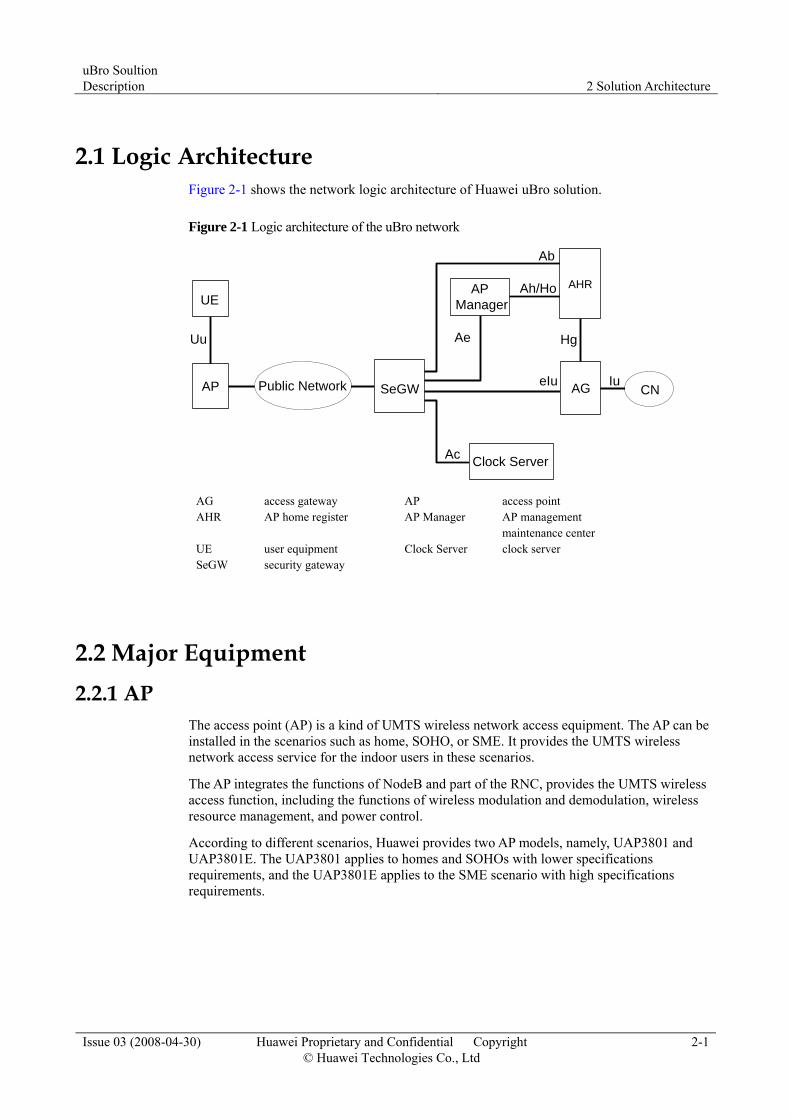
2.1 Logic Architecture Figure 2-1 shows the network logic architecture of Huawei uBro solution.
Figure 2-1 Logic architecture of the uBro network
IuPublic Network CN
Clock Server
UEAh/Ho
Ae
AP Manager
SeGW eIu
Ac
Ab
Uu
AP
AHR
AG
Hg
AG access gateway AP access point AHR AP home register AP Manager AP management
maintenance center UE user equipment Clock Server clock server SeGW security gateway
2.2 Major Equipment 2.2.1 AP
The access point (AP) is a kind of UMTS wireless network access equipment. The AP can be installed in the scenarios such as home, SOHO, or SME. It provides the UMTS wireless network access service for the indoor users in these scenarios.
The AP integrates the functions of NodeB and part of the RNC, provides the UMTS wireless access function, including the functions of wireless modulation and demodulation, wireless resource management, and power control.
According to different scenarios, Huawei provides two AP models, namely, UAP3801 and UAP3801E. The UAP3801 applies to homes and SOHOs with lower specifications requirements, and the UAP3801E applies to the SME scenario with high specifications requirements.

2 Solution Architecture uBro Soultion
Description
2-2 Huawei Proprietary and Confidential Copyright © Huawei Technologies Co., Ltd
Issue 03 (2008-04-30)
2.2.2 AG The access gateway (AG) is Huawei AG equipment with the model as SGSN9810. According to the requirements, Huawei provides two models of AGs, namely, independent AG and eSGSN.
If the AG does not integrate the SGSN function, the AG is an independent one. If the AG integrates the SGSN function, the AG is the enhanced SGSN (eSGSN). The eSGSN is an available mode of the AG in the uBro solution, telecom operators can select a model as required in practice. If not specified, the AG in this solution refers to the independent AG.
Independent AG Functions The independent AG performs the following functions:
Provides the enhanced Iu (eIu) interface to connect to the AP in order to manage and control the AP.
Provides a standard Iu interface to connect to the core NEs in the UMTS, such as the MSC Server, media gateway (MGW) and serving GPRS support node (SGSN), to forward data and signaling between the AP and the UMTS core network and between the CS domain and the PS domain.
eSGSN Functions The eSGSN performs the following functions:
Provides the enhanced Iu (eIu) interface to connect to the AP in order to manage and control the AP.
Provides a standard Iu-CS interface to connect to the core NEs in the UMTS, such as the MSC Server and MGW, to forward data and signaling between the AP and the CS domain of the UMTS core network.
To integrate the function of the SGSN, it provides a standard Gn interface to connect to the Gateway GPRS Support Node (GGSN) in the UMTS core network to forward data and signaling between the AP and the GGSN.
2.2.3 Clock Server The Clock Server locates in the uBro core network, and provides a precise clock source to the AP. The model of Huawei Clock Server is IPCLK1000.
Huawei Clock Server adopts the Clock over IP technology:
The Clock over IP technology is divided into two parts, namely, Server and Client. The IPCLK1000 acts as the Server and the AP acts as the Client.
The Server obtains the clock source from the clock equipment, and then provides the synchronous reference clock to the Client (AP) through the IP network in the form of IP packets after local phase-lock and hold-in.

uBro Soultion Description 2 Solution Architecture
Issue 03 (2008-04-30) Huawei Proprietary and Confidential Copyright © Huawei Technologies Co., Ltd
2-3
2.2.4 AHR The AP home register (AHR) locates in the uBro network managed by telecom operators.
Huawei AHR performs the following functions:
Provides the pilot information when the AP initiates the Boot flow. Provides the AP account-opening/account-canceling information and management of
subscription data. Provides the AP access control list and integrated database management. Provides the AP area management. Provides the AP authentication. Provides the AHR system management. Provides the AHR log management.
2.2.5 AP Manager The AP Manager locates in the uBro core network. It is Huawei-developed AP management platform and manages all the APs on the network in a unified manner.
The AP Manager performs the following functions:
AP configuration management AP fault management AP version management AP software management Task management Security Management Log Management
2.2.6 SeGW The SeGW locates in the entrance of the uBro core network. Huawei SeGW is Eudemon500/1000.
The SeGW performs the following functions:
Provides standard Fire Wall function. The SeGW provides security protection for the NEs in the uBro core network.
Provides the SeGW function. The SeGW provides security protection for the communications between the AP and NEs in the uBro core network through establishing IPSec VPN tunnel between the AP and SeGW.
2.2.7 M2000 M2000 locates in the uBro core network. Huawei M2000 is the unified management platform of Huawei mobile network. It can manage the NEs in the uBro core network in a unified form through this platform.

2 Solution Architecture uBro Soultion
Description
2-4 Huawei Proprietary and Confidential Copyright © Huawei Technologies Co., Ltd
Issue 03 (2008-04-30)
2.3 Technical Features of the uBro System The uBro network is a new network form, and introduces the following features:
Automatic Network Design The uBro system supports the following features about automatic network design:
Automatic configuraiton of the frequency point in the cell. The AP automatically selects the frequency point with the lowest interference as the frequency point of the AP cell. The AP selects the frequency point in the list of the AP cell frequency points.
Automatic configuration of scrambles in the cell. The AP detects scrambles to select the scramble with the lowest interference as the AP scramble.
Automatic configuration of AP adjacent cells. The AP detects the adjacent macro cells with or without the same frequency and completes the AP adjacent cell configuraiton automatically.
Automatic pilot power adjustment. The AP adjusts pilot power automatically according to the specific free numbers called by UEs.
Interference Detection After the logic cells are established, the AP can automatically detect the quality of uplink signals, and show the signal quality at the current position through the signal indicator on the panel, thus instructing users to adjust the AP installation angle to a suitable position.
The AP detects the interference signals in uplink receiving channels. The AP provides the interference indicator to show the signal quality at the current
position through the signal indicator on the AP panel. The AP supports interference threshold configuration, modification and query for manual
detection.
Location Detection The uBro system supports the following features about location detection:
The uBro system supports the configuration and query of the parameters of AP location detection policies.
The uBro system supports detection of location information of the macro network through detecting the public land mobile network (PLMN) and location area identification (LAI) to judge the validity of AP location. The invalid AP will be automatically prohibitted.
Location Indication When the UE accesses the AP cell and stays successfully, the AP must notify the UE of current network status in a certain way. The user knows the status for the convenience of further operation.
At present, the uBro system supports the following two modes of location indication:
Short message indication − The AP can send a short message. When the UE accesses the AP cell, the AP sends a
short message to the UE as notification. Telecom operators can set the contents of the message on the AP.
uBro Soultion Description 2 Solution Architecture
Issue 03 (2008-04-30) Huawei Proprietary and Confidential Copyright © Huawei Technologies Co., Ltd
2-5
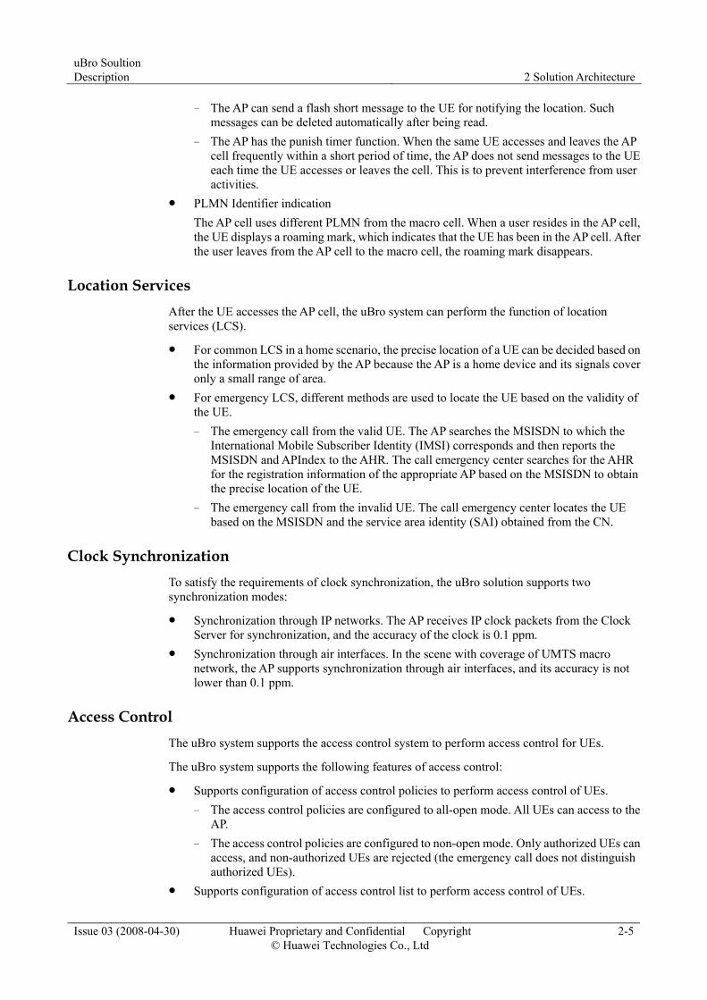
− The AP can send a flash short message to the UE for notifying the location. Such messages can be deleted automatically after being read.
− The AP has the punish timer function. When the same UE accesses and leaves the AP cell frequently within a short period of time, the AP does not send messages to the UE each time the UE accesses or leaves the cell. This is to prevent interference from user activities.
PLMN Identifier indication The AP cell uses different PLMN from the macro cell. When a user resides in the AP cell, the UE displays a roaming mark, which indicates that the UE has been in the AP cell. After the user leaves from the AP cell to the macro cell, the roaming mark disappears.
Location Services After the UE accesses the AP cell, the uBro system can perform the function of location services (LCS).
For common LCS in a home scenario, the precise location of a UE can be decided based on the information provided by the AP because the AP is a home device and its signals cover only a small range of area.
For emergency LCS, different methods are used to locate the UE based on the validity of the UE. − The emergency call from the valid UE. The AP searches the MSISDN to which the
International Mobile Subscriber Identity (IMSI) corresponds and then reports the MSISDN and APIndex to the AHR. The call emergency center searches for the AHR for the registration information of the appropriate AP based on the MSISDN to obtain the precise location of the UE.
− The emergency call from the invalid UE. The call emergency center locates the UE based on the MSISDN and the service area identity (SAI) obtained from the CN.
Clock Synchronization To satisfy the requirements of clock synchronization, the uBro solution supports two synchronization modes:
Synchronization through IP networks. The AP receives IP clock packets from the Clock Server for synchronization, and the accuracy of the clock is 0.1 ppm.
Synchronization through air interfaces. In the scene with coverage of UMTS macro network, the AP supports synchronization through air interfaces, and its accuracy is not lower than 0.1 ppm.
Access Control The uBro system supports the access control system to perform access control for UEs.
The uBro system supports the following features of access control:
Supports configuration of access control policies to perform access control of UEs. − The access control policies are configured to all-open mode. All UEs can access to the
AP. − The access control policies are configured to non-open mode. Only authorized UEs can
access, and non-authorized UEs are rejected (the emergency call does not distinguish authorized UEs).
Supports configuration of access control list to perform access control of UEs.
2 Solution Architecture uBro Soultion
Description
2-6 Huawei Proprietary and Confidential Copyright © Huawei Technologies Co., Ltd
Issue 03 (2008-04-30)
− Supports IMSI configuration for the access control list. Users add or delete the IMSI in the access control list to perform access control of UEs.
− Supports MSISDN configuration for the access control list. Users add or delete the MSISDN in the access control list to perform access control of UEs (this mode is supported only when the AG mode is eSGSN).
Cell Reselection The uBro system supports the following features of cell reselection:
When the UE is in the idle state, the UE can select between the AP cell and the macro cell or select between two AP cells.
The AP supports the configuration of the hierarchical cell structure (HCS) parameter. It allows the UE to first reside in the AP cell by surveying the valid HCS parameter.
Handoff The uBro system supports the unidirectional hard handoff, from the AP cell to the macro cell.
AP Security Authentication To avoid invalid AP access to the AG, the AG performs authentication to the accessed AP. Only valid AP can access the AG. The uBro system meanwhile supports the connection security between AP and OMC, thus ensuring that non-authorized users cannot monitor or control the AP.
The uBro system supports the following security authentication features of equipment:
The AP that can access to the AG supports password-based authentication. Supports authentication between the AP and operation & maintenance center (OMC).
QoS The core of QoS is to map the services in the uBro solution onto the various QoS priority levels and the transmission network.
QoS priority mapping ways are classified as follows:
The AP, AG and transmission equipment support the IP DiffServ to guarantee the differentiation services of mobile services over IP layer. The MAC layer adopts IEEE802.1P to guarantee differentiation services over the MAC layer.
The user end equipment such as multi-channel MODEM/ADSL supports the priority of the PVC to ensure QoS of the uBro services.
The uBro system supports DSLAM and 2-layer transmission network. It allocates independent virtual local area network (VLAN) to guarantee the QoS of the uBro services.
The uBro system supports the MPLS DiffServ/TE technology of the 3-layer transmission network to guarantee the QoS of the 3-layer transmission network.

uBro Soultion Description 2 Solution Architecture
Issue 03 (2008-04-30) Huawei Proprietary and Confidential Copyright © Huawei Technologies Co., Ltd
2-7
2.4 Interfaces The system interfaces of Huawei uBro solution are different in the cases of independent AG and eSGSN.
Independent AG When the AG is not integrated with the SGSN function, the interfaces of the uBro system are shown in Figure 2-2.
Figure 2-2 Interfaces in the uBro solution
Iu-PSAG
MSC Server/MGW
SGSN
UE
Iu-CS
APUu
eIu
Ah/Ab
Clock ServerAc
AP Manager
AHR
Ae
Ho
Hg
AG access gateway SGSN serving GPRS support node MGW media gateway MSC Server mobile switching center server AHR AP home register AP Manager AP management maintenance centerAP access point Clock Server clock server UE user equipment
2 Solution Architecture uBro Soultion
Description
2-8 Huawei Proprietary and Confidential Copyright © Huawei Technologies Co., Ltd
Issue 03 (2008-04-30)
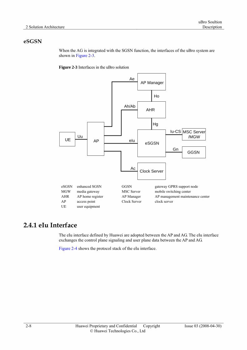
eSGSN When the AG is integrated with the SGSN function, the interfaces of the uBro system are shown in Figure 2-3.
Figure 2-3 Interfaces in the uBro solution
MSC Server/MGW
UE
Iu-CS
APUu
eIu
Ah/Ab
Clock ServerAc
AP Manager
AHR
Ae
Ho
Hg
eSGSN
GGSNGn
eSGSN enhanced SGSN GGSN gateway GPRS support node MGW media gateway MSC Server mobile switching center AHR AP home register AP Manager AP management maintenance center AP access point Clock Server clock server UE user equipment
2.4.1 eIu Interface The eIu interface defined by Huawei are adopted between the AP and AG. The eIu interface exchanges the control plane signaling and user plane data between the AP and AG.
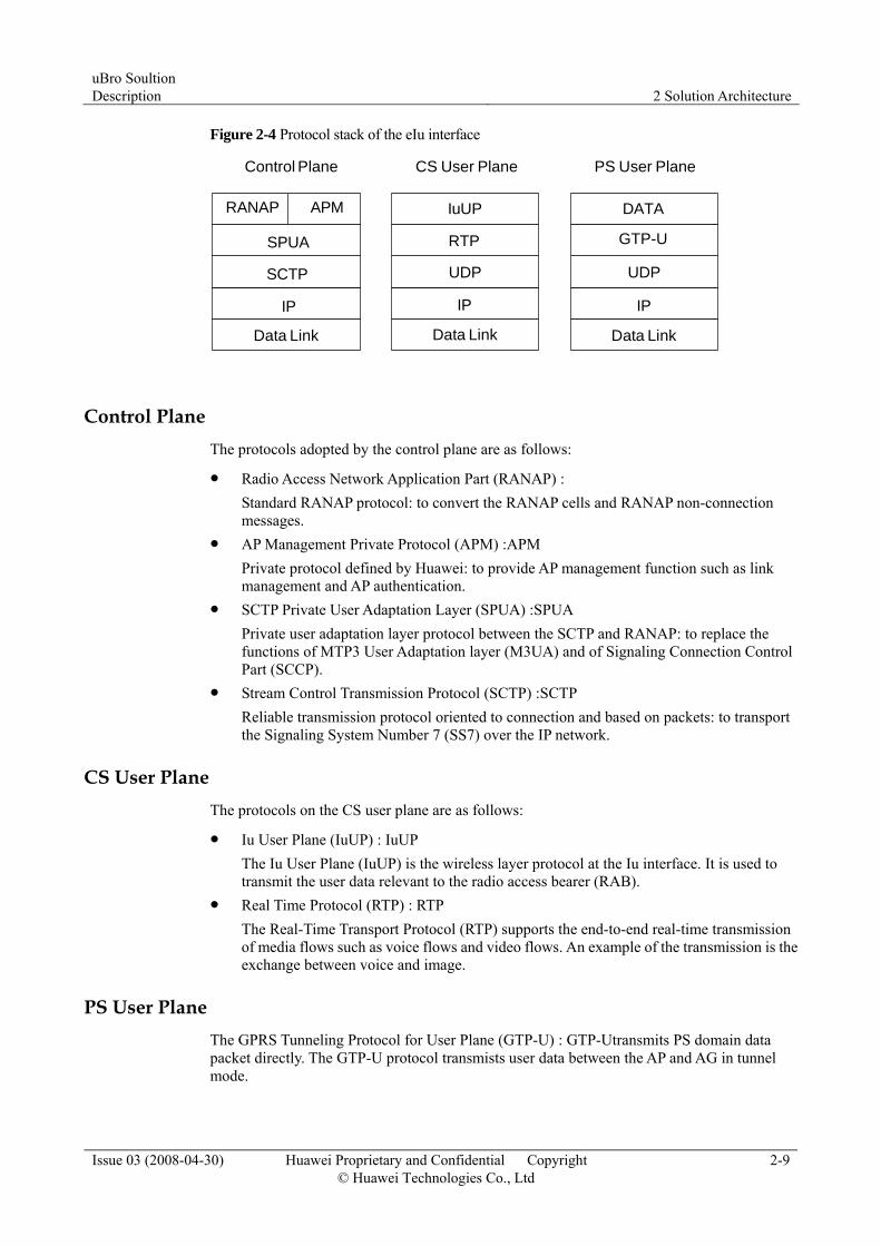
Figure 2-4 shows the protocol stack of the eIu interface.
uBro Soultion Description 2 Solution Architecture
Issue 03 (2008-04-30) Huawei Proprietary and Confidential Copyright © Huawei Technologies Co., Ltd
2-9
Figure 2-4 Protocol stack of the eIu interface
RANAP APM
Control Plane
DATA
PS User Plane
GTP-U
UDP
IP
IuUP
CS User Plane
RTP
IP
SPUA
SCTP
IP
Data Link Data Link Data Link
UDP
Control Plane The protocols adopted by the control plane are as follows:
Radio Access Network Application Part (RANAP) : Standard RANAP protocol: to convert the RANAP cells and RANAP non-connection messages.
AP Management Private Protocol (APM) :APM Private protocol defined by Huawei: to provide AP management function such as link management and AP authentication.
SCTP Private User Adaptation Layer (SPUA) :SPUA Private user adaptation layer protocol between the SCTP and RANAP: to replace the functions of MTP3 User Adaptation layer (M3UA) and of Signaling Connection Control Part (SCCP).
Stream Control Transmission Protocol (SCTP) :SCTP Reliable transmission protocol oriented to connection and based on packets: to transport the Signaling System Number 7 (SS7) over the IP network.
CS User Plane The protocols on the CS user plane are as follows:
Iu User Plane (IuUP) : IuUP The Iu User Plane (IuUP) is the wireless layer protocol at the Iu interface. It is used to transmit the user data relevant to the radio access bearer (RAB).
Real Time Protocol (RTP) : RTP The Real-Time Transport Protocol (RTP) supports the end-to-end real-time transmission of media flows such as voice flows and video flows. An example of the transmission is the exchange between voice and image.
PS User Plane The GPRS Tunneling Protocol for User Plane (GTP-U) : GTP-Utransmits PS domain data packet directly. The GTP-U protocol transmists user data between the AP and AG in tunnel mode.

2 Solution Architecture uBro Soultion
Description
2-10 Huawei Proprietary and Confidential Copyright © Huawei Technologies Co., Ltd
Issue 03 (2008-04-30)
2.4.2 Ab/Ah Interface The Ab and Ah interfaces are between the AP and AHR.
After the AP is powered on initially, the AP initiates the BOOT flow, and obtains the AP information and IP address of other NEs in the uBro core network from the AHR through the Ab interface.
When maintaining the AP attribute information, the AP and AHR communicate with each other through the Ah interface. When a user makes a call to change the customized information on the AP, such as the UE admission list and SAI, the AHR updates the AP information on initiative.
2.4.3 Ae Interface The Ae interface is between the AP and the AP Manager. The AP Manager manages the AP through the Ae interface that complies with the TR069 protocol.
2.4.4 Hg Interface The Hg interface is between the AG and AHR. In the password based AP authentication solution, the username and password are saved in the AHR. After receiving an authentication request from the AP, the AG must obtain the username and password from the AHR.
The validity of the AP location is detected through the Hg interface.
2.4.5 Ho Interface The Ho interface is between the AHR and the AP Manager. The AHR issues services and maintains user information of the AP.
When the AHR adds, changes, and deletes the home group data of the AP, the AHR sends the changed home group information to the AP Manager to ensure the consistency in the home groups between the AHR and the AP Manager.
When the AHR adds, changes, and deletes the user data of the AP, the AHR and AP Manager ensure the consistency in the user data of the AP through synchronization. After generating a synchronized data file, the AHR sends a message to notify the AP Manager of the generation. Then the AP Manager obtains the synchronized data file through FTP.
The AP Manager can only query the account information of the AHR.
2.4.6 Ac Interface The Ac interface is between the AP and Clock Server. It is for the AP to obtain the clock synchronization.
2.4.7 Uu Interface The standard Uu interface is between the UE and AP.
2.4.8 Iu-CS Interface The standard Iu-CS interface is between the AG and MSC Server/MGW.

uBro Soultion Description 2 Solution Architecture
Issue 03 (2008-04-30) Huawei Proprietary and Confidential Copyright © Huawei Technologies Co., Ltd
2-11
2.4.9 Iu-PS Interface The standard Iu-PS interface is between the AG and SGSN.
3 Networking Solution uBro Soultion
Description
3-0 Huawei Proprietary and Confidential Copyright © Huawei Technologies Co., Ltd
Issue 03 (2008-04-30)
3 Networking Solution
About This Chapter
The following table lists the contents of this chapter.
Section Describes
3.1 Service Networking Service networking solution of the uBro solution.
3.2 Transmission Networking Transmission networking solution of the uBro solution.
uBro Soultion Description 3 Networking Solution
Issue 03 (2008-04-30) Huawei Proprietary and Confidential Copyright © Huawei Technologies Co., Ltd
3-1
3.1 Service Networking Service networking refers to the networking mode of the uBro network oriented to different service strategies.
3.1.1 Independent AG Networking Solution
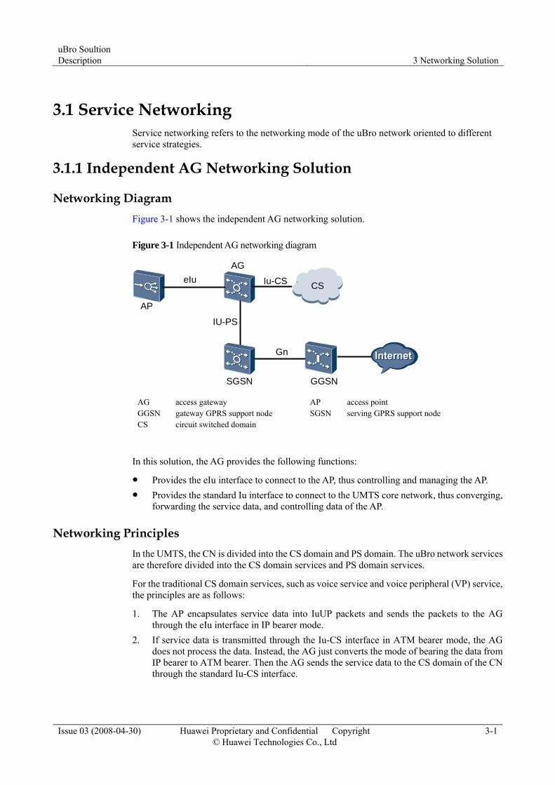
Networking Diagram Figure 3-1 shows the independent AG networking solution.
Figure 3-1 Independent AG networking diagram
AP
GGSN
AG
Gn
eIuCSIu-CS
IU-PS
SGSN
AG access gateway AP access point GGSN gateway GPRS support node SGSN serving GPRS support node CS circuit switched domain
In this solution, the AG provides the following functions:
Provides the eIu interface to connect to the AP, thus controlling and managing the AP. Provides the standard Iu interface to connect to the UMTS core network, thus converging,
forwarding the service data, and controlling data of the AP.
Networking Principles In the UMTS, the CN is divided into the CS domain and PS domain. The uBro network services are therefore divided into the CS domain services and PS domain services.
For the traditional CS domain services, such as voice service and voice peripheral (VP) service, the principles are as follows:
1. The AP encapsulates service data into IuUP packets and sends the packets to the AG through the eIu interface in IP bearer mode.
2. If service data is transmitted through the Iu-CS interface in ATM bearer mode, the AG does not process the data. Instead, the AG just converts the mode of bearing the data from IP bearer to ATM bearer. Then the AG sends the service data to the CS domain of the CN through the standard Iu-CS interface.
3 Networking Solution uBro Soultion
Description
3-2 Huawei Proprietary and Confidential Copyright © Huawei Technologies Co., Ltd
Issue 03 (2008-04-30)
3. If service data is transmitted through the Iu-CS interface in IP bearer mode, the AG does not have to convert between the IP bearer and the ATM bearer. Instead, the AG directly forwards service data to the CS domain of the CN.
4. After the service data reaches the CS domain of the CN, the CN considers the service data as ordinary data of UMTS CS domain service and processes the service data.
For the PS domain services, the realization principles are the same as that in the traditional UMTS.
Networking Features The solution is easy to implement. The solution requires only a little change in the current NEs. The AG at the access side can connect to the CN through the standard Iu interface. Telecom operators do not have to test the interconnection of other interfaces.
3.1.2 eSGSN Networking Solution
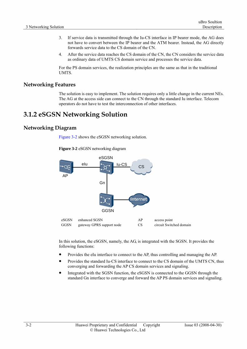
Networking Diagram Figure 3-2 shows the eSGSN networking solution.
Figure 3-2 eSGSN networking diagram
AP
GGSN
eSGSN
Gn
eIu CSIu-CS
eSGSN enhanced SGSN AP access point GGSN gateway GPRS support node CS circuit Switched domain
In this solution, the eSGSN, namely, the AG, is integrated with the SGSN. It provides the following functions:
Provides the eIu interface to connect to the AP, thus controlling and managing the AP. Provides the standard Iu-CS interface to connect to the CS domain of the UMTS CN, thus
converging and forwarding the AP CS domain services and signaling. Integrated with the SGSN function, the eSGSN is connected to the GGSN through the
standard Gn interface to converge and forward the AP PS domain services and signaling.

uBro Soultion Description 3 Networking Solution
Issue 03 (2008-04-30) Huawei Proprietary and Confidential Copyright © Huawei Technologies Co., Ltd
3-3
Networking Principles For the realization principles of the CS domain services, see. 3.1.1 Independent AG Networking Solution
For PS domain services, because the eSGSN is integrated with the SGSN, the eSGSN can process the data on the control plane of PS domain services and forward the PS domain service data to the GGSN.
Networking Features The eSGSN networking solution possesses the following features:
This solution decreases the investment in PS domain equipment. Because the eSGSN is integrated with the SGSN, this decreases the investment in the SGSN, thus reducing the operation cost of telecom operators.
This solution decreases the number of times of routing service data. Because the eSGSN is integrated with the SGSN, service data can reach the GGSN directly without passing through the SGSN. This decreases the frequency of forwarding service data in the SGSN and reduces the delay time in transmitting service data.
This solution is flattened. − Network layers, maintenance workload, and maintenance cost are decreased. − The flattened network is easy to expand.
This solution is easy to upgrade. Telecom operators can upgrade the network only by upgrading appropriate software.
3.2 Transmission Networking Transmission networking refers to the networking mode for the network from the AP to the uBro CN.
3.2.1 xDSL Access Networking Solution Because the current families and SOHO scenarios use the wideband access ADSL/ADSL2+ commonly, the transmission networking of Huawei uBro solution supports the xDSL access topology.
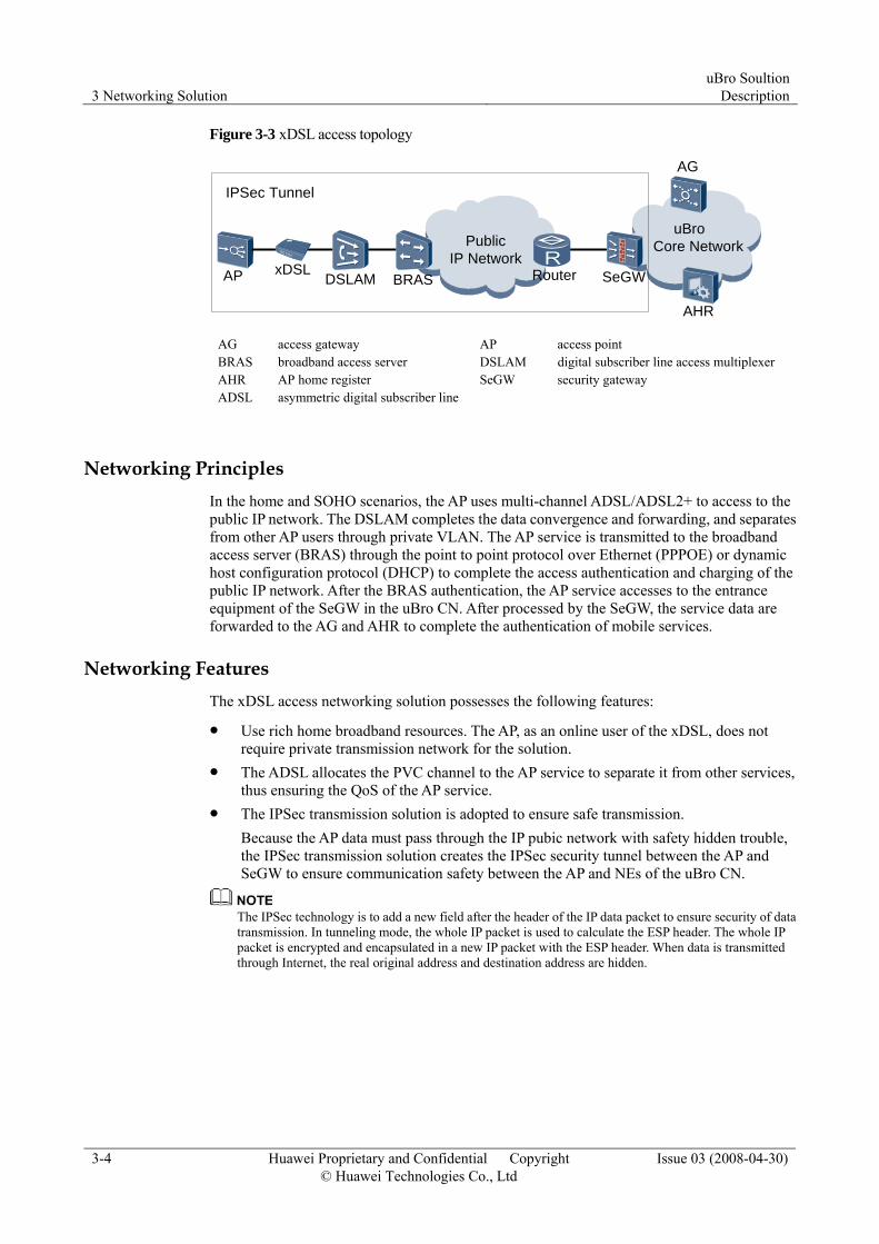
Figure 3-3 shows the xDSL access topology.
3 Networking Solution uBro Soultion
Description
3-4 Huawei Proprietary and Confidential Copyright © Huawei Technologies Co., Ltd
Issue 03 (2008-04-30)
Figure 3-3 xDSL access topology
AP
IPSec Tunnel
xDSL
AHR
AG
uBro Core Network
RouterBRASDSLAM
Public IP Network
SeGW
AG access gateway AP access point BRAS broadband access server DSLAM digital subscriber line access multiplexer AHR AP home register SeGW security gateway ADSL asymmetric digital subscriber line
Networking Principles In the home and SOHO scenarios, the AP uses multi-channel ADSL/ADSL2+ to access to the public IP network. The DSLAM completes the data convergence and forwarding, and separates from other AP users through private VLAN. The AP service is transmitted to the broadband access server (BRAS) through the point to point protocol over Ethernet (PPPOE) or dynamic host configuration protocol (DHCP) to complete the access authentication and charging of the public IP network. After the BRAS authentication, the AP service accesses to the entrance equipment of the SeGW in the uBro CN. After processed by the SeGW, the service data are forwarded to the AG and AHR to complete the authentication of mobile services.
Networking Features The xDSL access networking solution possesses the following features:
Use rich home broadband resources. The AP, as an online user of the xDSL, does not require private transmission network for the solution.
The ADSL allocates the PVC channel to the AP service to separate it from other services, thus ensuring the QoS of the AP service.
The IPSec transmission solution is adopted to ensure safe transmission. Because the AP data must pass through the IP pubic network with safety hidden trouble, the IPSec transmission solution creates the IPSec security tunnel between the AP and SeGW to ensure communication safety between the AP and NEs of the uBro CN.
The IPSec technology is to add a new field after the header of the IP data packet to ensure security of data transmission. In tunneling mode, the whole IP packet is used to calculate the ESP header. The whole IP packet is encrypted and encapsulated in a new IP packet with the ESP header. When data is transmitted through Internet, the real original address and destination address are hidden.

uBro Soultion Description 3 Networking Solution
Issue 03 (2008-04-30) Huawei Proprietary and Confidential Copyright © Huawei Technologies Co., Ltd
3-5
3.2.2 Ethernet Access Networking Solution Because the current SME uses the enterprise LAN to access to the IP network, the transmission networking of Huawei uBro solution adopts the Ethernet access networking mode.
Figure 3-4 shows the Ethernet access topology.
Figure 3-4 Ethernet access topology
AP SeGW
E2E VPN
LAN SW
Public IP Network
AHR
AG
uBro Core Network
Router Router
AG access gateway AP access point BRAS broadband access server LAN SW local area network switch AHR AP home register SeGW security gateway
Networking Principles In the Ethernet access networking solution, the AP is connected to the public IP network through the enterprise LAN and separated from other users through the private VLAN. The AP service directly accesses to the entrance equipment of the uBro CN, namely, SeGW, through the public IP network, and then the SeGW forwards the data to the AG and AHR to complete the authentication of the mobile services. The AP and AG adopt the PPPoE or DHCP authentication mode to complete the authentication of the mobile service.
Networking Features The Ethernet access networking solution possesses the following features:
The Ethernet access networking solution allocates private VLAN and MPLS DiffServ/TE mode to the AP service to ensure the QoS of the uBro services.
The Ethernet access networking mode uses the E2E VPN to ensure the security of the transmission.

4 Security Solution uBro Soultion
Description
4-0 Huawei Proprietary and Confidential Copyright © Huawei Technologies Co., Ltd
Issue 03 (2008-04-30)
4 Security Solution
About This Chapter
The following table lists the contents of this chapter.
Section Describes
4.1 Overview of the Authentication Security Solution
Classification of security solutions in the uBro solution.
4.2 Network equipment security Security policies in the NE security part of the uBro solution.
4.3 Network Security Security policies in the network security part of the uBro solution.
4.4 Operation and Maintenance Security
Security policies in the OM security part of the uBro solution
uBro Soultion Description 4 Security Solution
Issue 03 (2008-04-30) Huawei Proprietary and Confidential Copyright © Huawei Technologies Co., Ltd
4-1
4.1 Overview of the Authentication Security Solution The security system of the uBro solution consists of the following aspects:
NE security Network Security Operation and Maintenance Security
4.2 Network equipment security Network equipment security refers to the following security measures provided by NEs:
AP equipment security − The AP and AG support password-based authentication. − The local maintenance AP and remote maintenance AP supports the NE access
authentication based on password. − The AP supports anti-DOS attack in the operating system and sensitive data
encryption. − The AP supports the ACL control UE access to prevent the access from non-authorized
UE. CN equipment security
− The operating system needs strengthening. − Installing firewalls on NEs − Installing security patches − Detecting the communication between NEs − Virus prevention − Sensitive data encryption
4.3 Network Security The features of the uBro solution are to use the public network to expand the mobile network to homes, to provide high quality of UMTS wireless voice and data service. How to ensure the network security as a whole, especially to prevent threaten from the mobile CN, is the most tricky issue in the uBro security solution.
4.3.1 Security Domain Partition The uBro system prevents the various network security from being threatens by partitioning different security domains.
Not-trusted domain − Home network domain and enterprise LAN domain − Public network domain
Trusted domain
4 Security Solution uBro Soultion
Description
4-2 Huawei Proprietary and Confidential Copyright © Huawei Technologies Co., Ltd
Issue 03 (2008-04-30)
− uBro CN domain − UMTS mobile CN domain
4.3.2 Border Protection The security equipment like firewall is deployed between different security domains to perform border protection. The keystone is the security border protection between the uBro CN domain and public network domain.
The security prevention policies of the firewall are as follows:
Attack Prevention Policy ACL policy and data packet filtering policy NAT Policy Dual gateway policies
4.3.3 Network Anti-Attack Through firewall deployment and security setting, the network security prevents the following attacks:
Anti-DoS (Denial of Service) network attack Anti-scan network attack Anti-malformation message attack
4.3.4 Network Access Authentication and Access Control
Network Access Authentication Network access authentication refers to identifying the equipment that accesses the network to achieve the following aims:
Preventing the access from the unauthorized AP Preventing attackers from accessing the network
The access authentication of the uBro solution consists of the following:
Broadband access authentication After accessing the ADSL broadband network, the AP is authenticated before obtaining an IP address. This authentication can be in the DHCP mode or PPPoE mode.The enterprise AP can access to the IP public network directly through the enterprise LAN, and the broadband authentication is not required.
Mobile network access authentication When accessing the mobile network through IPSec or DHCP mode, the AP and the AG are authenticated through key negotiation sharing and the authentication of the user name and password. The protocols used in this authentication are IKEv1.
Subsequent versions will support IKEv2 and EAP-Authentication and Key Agreement (EAP-AKA).

uBro Soultion Description 4 Security Solution
Issue 03 (2008-04-30) Huawei Proprietary and Confidential Copyright © Huawei Technologies Co., Ltd
4-3
Access Control The uBro system supports the access control system to perform access control for UEs. The access control system makes the AP can be accessed by the authorized UE only, and rejects non-authorized UE accessing to the uBro network.
4.3.5 Transmission Security For the bearer network, the transmission security is to prevent the control plane data and user plane data of the AP from being stolen, counterfeited or damaged, thus ensuring the security and integrality of the data transmission.
The uBro solution supports the following features about transmission security:
Supports end-to-end VLAN and MPLS VPN technologies to realize separation between AP users. In the fixed access network, different PVC and VLAN are allocated to realize separation between AP services and non-AP services.
Supports the access control list (ACL) mode to define the protected data flow. The messages allowed by the ACL are protected, and those rejected by the ACL are not protected.
Supports the IPSec protocol. The IPSec security tunnel is established between the AP and SeGW to protect the defined data flow, Thus realizing transmission safety over the bearer network. The IPSec tunnel provides the following security features: − Data confidentiality. − Data integrity − Anti-replay
Supports the Internet Key Exchange protocol (IKE). − The IKE provides safety bidirectional authentication. − The IKE supports the test and traversing of the Network Address Translation (NAT).
Supports the Encapsulating Security Payload (ESP) protocol. − The ESP can encrypt the IP messages. − ESP authenticates the integrity of IP packets to judge whether the packets are corrupted
during transmission. − The ESP protocol supports the traversing of the NAT.
The transmission between the AP and AG adopts the IPSec tunneling mode based on the ESP/IKE protocols. The IPSec key negotiation management can be based on the IKEV1 standard, and supports multiple authentication and key management methods such as the pre-shared key and EAP-SIM. Subsequent versions will support IKEv2 and EAP-Authentication and Key Agreement (EAP-AKA).

4 Security Solution uBro Soultion
Description
4-4 Huawei Proprietary and Confidential Copyright © Huawei Technologies Co., Ltd
Issue 03 (2008-04-30)
4.4 Operation and Maintenance Security The OM security refers to the security of network management, and its security policies are as follows:
Integrated NE management − The AP Manager manages all the AP equipment on the network. − M2000 manages the uBro CN NEs as a whole.
Integrated management of accounts and rights Prevent illegal users from attacking and destroying the system through identity forgery, authority-exceeding access, password-guessing, and password file-stolen, thus improving the security of the system. The following measures are taken to protect the security of OM accounts: − All accounts of NE administrators are created and managed by the NM system (NMS)
in a centralized manner. − All account information is stored in the network management (NM) system.
Integrated log management − The NM can collect / filter the log information of every NE. − Provides the functions of checking / summing up/ analyzing the logs. − Provides the integrated storage / backup functions of the logs.
5 Service Operation uBro Soultion
Description
5-0 Huawei Proprietary and Confidential Copyright © Huawei Technologies Co., Ltd
Issue 03 (2008-04-30)
5 Service Operation
About This Chapter
The following table lists the contents of this chapter.
Section Describes
5.1 Service Application How to apply for the AP.
5.2 Installation of the AP How to install the AP.
5.3 Interference Processing of the AP
How to make the AP free from interference.
5.4 Movement of the AP Movement of the AP.
5.5 Deregistration of the AP Movement of the AP.
5.6 Upgrade of the AP How to upgrade the AP.
5.7 Maintenance of the AP How to maintain the AP.
uBro Soultion Description 5 Service Operation
Issue 03 (2008-04-30) Huawei Proprietary and Confidential Copyright © Huawei Technologies Co., Ltd
5-1
5.1 Service Application The current AP authentication adopts the authentication mode based on the user name and password. There are two ways to issue the services.
Password Directly Written Into the AP The telecom operator writes the password into the AP when delivering the AP. The user applies for purchase in the business hall and submits the user information. The
telecom operator delivers the AP to the user and opens an account using the user information in the AHR.
After hardware installation of the AP, the user connects the AP to the internet, and the AP passes the password authentication automatically before normal operation.
Password in an Envelop The user applies for purchasing the service and submits the user information, and the
telecom operator provides the envelop containing the password. After installing the hardware of the AP, the user can log in to the AP local WEB
maintenance webpage through a home PC. Then the user enters the password and other information.
After the AP accesses the Internet, it can start to work after passing the password authentication.
5.2 Installation of the AP The AP installation supports desk installation and mounted installation. For specific installation methods, see relevant AP installation manuals.
5.3 Interference Processing of the AP After being interfered, the AP shows the severity of interference through an indicator. If the indicator is yellow, it indicates that the severity of the interference is minor. If the indicator is red, it indicates that the severity of the interference is major.
The interference to the AP can be classified into temporary interference and permanent interference.
Temporary Interference If there is temporary interference in the AP, the AP can recover through power control.
5 Service Operation uBro Soultion
Description
5-2 Huawei Proprietary and Confidential Copyright © Huawei Technologies Co., Ltd
Issue 03 (2008-04-30)
Permanent Interference If there is permanent interference in the AP, the AP cannot recover. In this case, users must move the AP to a new location until the indicator becomes green.
If users cannot make the AP free from the interference through moving the AP, they can turn to the customer service call of the telecom operator to report the fault. Then maintenance engineers adjust the wireless parameters of the AP on the AP Manager to decrease the interference severity.
5.4 Movement of the AP According to the service area of the telecom operator, the movement of the AP consists of valid movement and invalid movement.
Valid Movement Valid movement refers to moving the AP within the service area of the appropriate telecom operator. If a user moves the AP to a new place within the original service area, the user can still use the AP after installing it correctly.
Invalid Movement Invalid movement refers to moving the AP out of the service area of the appropriate telecom operator.
The AP performs the LCS function, so it can judge whether it is moved out of the original service area. The AP on the invalid position will be prohibited.
5.5 Deregistration of the AP The deregistration of the AP refers to the process during which a user deregisters the service of the AP. After a user sends a request for deregistering the AP, the telecom operator needs to deregister the user data from the NEs of the uBro central office.
5.6 Upgrade of the AP To provide new services or remove faults from software, the telecom operator needs to upgrade AP software. Software upgrade is implemented automatically between the AP and the NMS. It is recommended to upgrade the software once or twice every year. The upgrade does not affect the use of the AP.
The software can be upgraded in the following scenarios:
Specific customer requirements are to be fulfilled. A serious fault in the software must be removed or new functions are to be performed.

uBro Soultion Description 5 Service Operation
Issue 03 (2008-04-30) Huawei Proprietary and Confidential Copyright © Huawei Technologies Co., Ltd
5-3
5.7 Maintenance of the AP When the AP becomes faulty (normally indicated by the state indicator), users can restart the AP manually to restore the AP. If the fault still exists, users can take the following measures:
Remote fault diagnosis mode The user makes a customer service call to report the fault. The engineer analyzes the fault identification data of the AP online and removes the fault by changing configuration data or upgrading the software.
Onsite maintenance mode If the AP cannot be restored remotely, the telecom operator sends a maintenance engineer to the site for fault maintenance. If the AP cannot be restored onsite, the maintenance engineer brings the faulty AP back to the telecom operator. During the maintenance period, the telecom operator can lend a AP for temporary use to the user.

6 Operation and Maintenance uBro Soultion
Description
6-0 Huawei Proprietary and Confidential Copyright © Huawei Technologies Co., Ltd
Issue 03 (2008-04-30)
6 Operation and Maintenance
About This Chapter
The following table lists the contents of this chapter.
Section Describes
6.1 O&M System The O&M architecture of the uBro solution.
6.2 O&M System of the AP The O&M functions of the AP in the uBro solution.
6.3 O&M System of Central-Office Equipment
The O&M functions the equipment in the uBro central office.

uBro Soultion Description 6 Operation and Maintenance
Issue 03 (2008-04-30) Huawei Proprietary and Confidential Copyright © Huawei Technologies Co., Ltd
6-1
6.1 O&M System Figure 6-1 shows the architecture of the O&M system of the uBro solution.
Figure 6-1 Architecture of the O&M system
AP ManagerGUI&Tookit
Terminal Equipment Mangement
Central-Office Equipment Management
AP ManagerServer
SeGW
AP
OSS/AHR
M2000 GUI
M2000 Server
AHR AG ClockServer SeGW LMT LMT
The O&M system of the uBro solution as shown in Figure 6-1 consists of two parts in the vertical direction:
Terminal equipment management Central-office equipment management
In the horizontal direction, the O&M system of the solution consists of three parts, namely, graphical user interface (GUI), AP Manager, and NE and local maintenance terminal (LMT).
The line between the AP Manager and the AHR shows that the AP Manager interacts with the AHR to obtain the basic information of the managed AP.
6.1.1 Solution of Terminal Equipment Management Terminal equipment management refers to maintaining the terminal equipment remotely. It possesses the following features:
Remote maintenance The OMC identifies and removes the fault of the terminal equipment remotely, so that maintenance engineers can decrease the number of times of onsite support or do not have to provide onsite support.
Passive maintenance The user reports a fault to the telecom operator. Then the telecom operator takes measures to remove the fault. Normally maintenance engineers do not collect O&M data from the AP on initiative.

6 Operation and Maintenance uBro Soultion
Description
6-2 Huawei Proprietary and Confidential Copyright © Huawei Technologies Co., Ltd
Issue 03 (2008-04-30)
6.1.2 Solution of Central-Office Equipment Management The central-office equipment is managed by the M2000 remotely and managed by the LMT locally. For details about maintenance, see 6.3 "O&M System of Central-Office Equipment"
6.2 O&M System of the AP The system of the AP consists of three parts:
AP Manager AP Manager Toolkit AP LMT
6.2.1 AP Manager The AP Manager, as the centralized NMS of the AP, is a Web-based maintenance system.
The AP Manager considers the requirements of users for equipment operation and maintenance and performs the powerful O&M functions for users. The AP performs the following O&M functions:
Configuration management Software Management Fault Management Performance Management Test Management
Configuration Management Configuration management involves the following functions:
The AP checks the consistency of the added data, deleted data, and changed data. The AP supports static data configuration and dynamic data configuration.
− If data is configured dynamically, the data takes effect immediately after it is changed. − If data is configured statically, the changed data takes effect only after the AP is reset.
In remote maintenance mode, the AP configures data automatically when it is powered on or configures data online.
Software Management Software management involves the following functions:
The AP supports upgrade of versions in batches in remote maintenance mode. The AP supports upgrade of the version of a single NE.

uBro Soultion Description 6 Operation and Maintenance
Issue 03 (2008-04-30) Huawei Proprietary and Confidential Copyright © Huawei Technologies Co., Ltd
6-3
Fault Management Fault management involves the following functions:
Supports the query of equipment status. It allows querying equipment states in batches in remote maintenance mode.
Provides the measures for identifying faults. The measures include interface tracing, signaling tracing, and log uploading.
Performance Management The AP provides the performance data that reflects system operation. By analyzing this data, maintenance personnel can know the operation of the network and find the reasons for the decrease in quality to provide basic data for network optimization.
Test Management Test management involves the following functions:
Equipment performance statistic Utilization of the central processing unit (CPU).
Service performance test RF performance 141 test and statistics data of the occupation of service resources.
6.2.2 AP Manager Toolkit You can obtain the AP Manager toolkit from the website and install it on your PC. The AP Manager toolkit consists of the following tools:
Equipment Diagnosis Alarmlog Browser Tool Performance Browser Tool Trace Viewer Monitor Viewer
Equipment Diagnosis Users need to install the equipment diagnosis software on the client first and then run the program. After that, they need to enter the IP addresses of the agent server and of the AP. They can use the tool after authentication succeeds.
This tool performs the following functions:
Tracing messages This tool can trace the messages at the Iu, Uu, Stream Control Transmission Protocol (SCTP), RNC Signaling Processing Unit (SPUA), CDT, and eIu interfaces of the AP, and save the messages in a file.
Monitoring CPU usage This tool can monitor the changes in the CPU usage of the AP and save the changes in a file.
Performing 141 test
6 Operation and Maintenance uBro Soultion
Description
6-4 Huawei Proprietary and Confidential Copyright © Huawei Technologies Co., Ltd
Issue 03 (2008-04-30)
This tool can test radio frequency indexes. Monitoring performance in real time
This tool can monitor temperature and cell performance in real time.
Alarmlog Browser Tool The maintenance personnel can upload the alarm files generated by the NEs to the M2000 server through the AP Manager. This alarmlog browser tool is used to view the alarm files.
The AP provides users with the alarms only related to users.
Performance Browser Tool The maintenance personnel can upload the performance files generated by the NEs to the M2000 Server through the AP Manager. The performance browser tool is used to view the performance files.
Trace Viewer The equipment diagnosis saves the traced interface messages of the AP in a file.The maintenance personnel can use the Trace Viewer to view these files.
Monitor Viewer The equipment diagnosis saves the CPU usage of the AP as a file. The maintenance personnel can use the Monitor Viewer to view these files.
6.2.3 AP LMT The AP LMT is the PC used by the onsite maintenance personnel. The onsite maintenance personnel can access to the AP built-in maintenance application through the IE browser.
The AP LMT allows users to perform the following operations:
Viewing AP status Viewing and changing AP configuration parameters Uploading the logs generated on the AP Loading software
Users are not recommended to change configuration parameters, uploading the logs generated on the AP, or load software, because these functions are provided for maintenance engineers.

uBro Soultion Description 6 Operation and Maintenance
Issue 03 (2008-04-30) Huawei Proprietary and Confidential Copyright © Huawei Technologies Co., Ltd
6-5
6.3 O&M System of Central-Office Equipment 6.3.1 AG
As central-office equipment, the AG is maintained through the M2000 and LMT. Its maintenance operations are similar to those of other central-office equipment.The O&M system of the AG performs the following functions:
Configuration management Performance management Alarm management Software management Tracing management Security management
Configuration Management Configuration management refers to adding, deleting, changing, and querying system data. The AG supports dynamic data configuration and static data configuration.
Dynamic data configuration refers to changing data without stopping the system operation.
Static data configuration refers to a process during which administrators edit MML.txt offline first and load it, and then restart the system to validate the changed data.
Performance Management Performance management refers to collecting the data that reflects network operation from the AG and the network around it.
The AG automatically reports the result of each index in every measurement period to the M2000 server.
Administrators can query, sort, and draw the results of performance measurement on the M2000 client.
Alarm Management Alarm management refers to monitoring NEs. It is applied in routine maintenance.
The AG generates alarms and sends them to the M2000 or LMT through the human-machine language (MML) interface in real time. The AG can connect to an alarm box, which generates audible and visible alarms to prompt maintenance personnel.
The alarms reported by the AG are classified into fault alarms and event alarms. Based on alarm severity, fault alarms are classified into critical alarms, major alarms, minor alarms, and warning alarms. Maintenance personnel browse, query, configure, maintain, and filter alarms on the alarm console or maintenance console.

6 Operation and Maintenance uBro Soultion
Description
6-6 Huawei Proprietary and Confidential Copyright © Huawei Technologies Co., Ltd
Issue 03 (2008-04-30)
Software Management Software management refers to upgrading the software or expanding the network to add new features or remove faults. Software upgrade refers to managing version files and patch files. Version files and patch files are downloaded from the version server to the AG through FTP, and then the software and patch are loaded and activated locally.
The AG allows installing patches to remove faults online without stopping services.
Tracing Management Tracing management is a powerful tool in NE maintenance.
The AG can trace the eIu interface, the Iu interface. It can also trace the protocols such as Message Transfer Part-Broadband (MTP3B), SCCP, Signaling ATM Adaptation Layer (SAAL), ATM Adaptation Layer 2 (AAL2), and SCTP.
Maintenance personnel can save tracing results as required and query the results through the tracing reviewing tool when necessary.
Security Management Security management refers to controlling operators and their rights to ensure that they perform operations within the authorization range. The AG performs security management by managing operators and command groups.
6.3.2 eSGSN For the O&M functions of the eSGSN, see 6.3.1 "AG."
6.3.3 Clock Server The Clock Server can meet the requirements of users for equipment operation and maintenance. It performs the following powerful O&M functions for users:
Security management Configuration management Software management Alarm management Log management
Security Management Security management of the Clock Server involves the following functions:
The clock server sets multiple levels of operator rights. The clock server controls the hierarchical operation right system to protect the security of NE operation.
The clock server protects the operator's information. If an operator does not operate an NE for a long time, the O&M interface is locked automatically.

uBro Soultion Description 6 Operation and Maintenance
Issue 03 (2008-04-30) Huawei Proprietary and Confidential Copyright © Huawei Technologies Co., Ltd
6-7
Configuration Management Configuration management is mainly applied in NE maintenance and data configuration. Configuration management supports the check of the consistency of configuration data. Data can be configured dynamically or statically.
If data is configured dynamically, the data takes effect immediately after it is changed. If data is configured statically, the changed data takes effect only after the clock server is
restarted.
Software Management Software management refers to managing and upgrading software versions.
Alarm Management The alarm management system of the Clock Server detects and reports the faults of NEs in real time. It also displays alarms and the suggestions for clearing the alarms on the M2000 and LMT.
The alarm management system of the LMT or M2000 can connect to an alarm box through a serial port. The alarm box generates audible and visible alarms, and sends the alarms that are subscribed by users to the mobile phones or pagers of the maintenance personnel. This helps the maintenance personnel to obtain the information of faulty NEs in time.
Log Management The clock server records the operations of NEs in real time and saves the records as operation logs. This helps to identify and solve problems.
6.3.4 AHR The AHR is a server. Seen from NM, the AHR performs the alarm management function. The AHR connects to the NMS through the Simple Network Management Protocol (SNMP) and performs routine maintenance through the Telnet.
6.3.5 SeGW The SeGW is connected to the M2000 for management. The M2000 supports alarm management. Data configuration and upgrade are implemented through the Telnet function of the SeGW.

7 Reference Information uBro Soultion
Description
7-0 Huawei Proprietary and Confidential Copyright © Huawei Technologies Co., Ltd
Issue 03 (2008-04-30)
7 Reference Information
About This Chapter
The following table lists the contents of this chapter.
Section Describes
7.1 System Performance Performance parameters of the major NEs in the uBro system.
7.2 Data Homing Data homing on the NEs in the uBro solution.
7.3 Referenced Standards and Protocols
Standards and protocols that the uBro solution adopts.

uBro Soultion Description 7 Reference Information
Issue 03 (2008-04-30) Huawei Proprietary and Confidential Copyright © Huawei Technologies Co., Ltd
7-1
7.1 System Performance 7.1.1 AP
Table 7-1 lists the system performance parameters of Huawei AP.
Table 7-1 AP system performance parameters
Item UAP3801 UAP3801E
Frequency band
Uplink: 1920 MHz – 1980 MHz Downlink: 2110 MHz - 2170 MHz
Uplink: 1920 MHz – 1980 MHz Downlink: 2110 MHz - 2170 MHz
Maximum transmit power
15 dBm (30 mW) 18 dBm (63 mW)
Number of telecom operators
A single telecom operator; a single cell
A single telecom operator; a single cell
Transceiver diversity
Not supported Not supported
Receiver sensitivity
< –107dBm < –112dBm
Service capability
Voice: 12.2 kbit/s (4) Data: 7.2 Mbit/s (DL)/1.44 Mbit/s (UL)
Voice: 12.2 kbit/s (16) Data: 7.2 Mbit/s (DL)/1.44 Mbit/s (UL)
Clock precision
±0.1 ppm ± 0.1 ppm
7.1.2 AG Table 7-2 lists the system performance parameters of Huawei AG.
Table 7-2 AG system performance parameters
Item Parameter
Data forwarding capability in the PS domain 10 Gbit/s
Voice forwarding capability in the CS domain 7500 Erl
Number of managed APs 50000
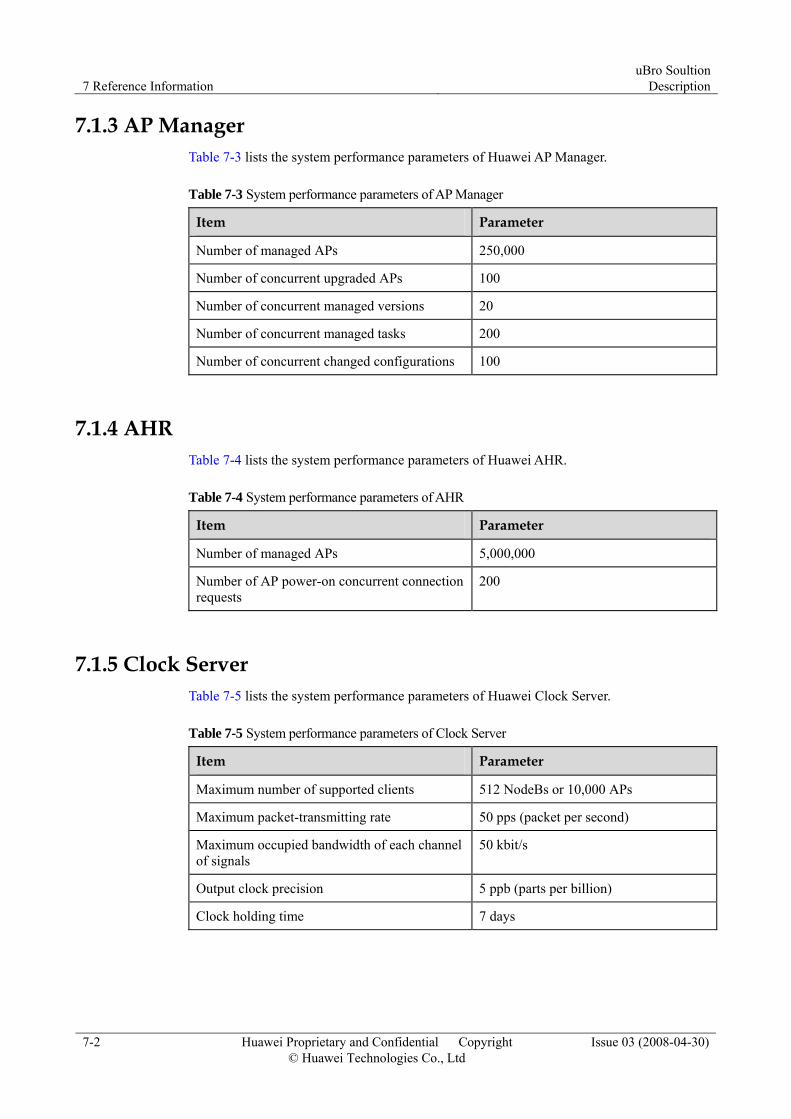
7 Reference Information uBro Soultion
Description
7-2 Huawei Proprietary and Confidential Copyright © Huawei Technologies Co., Ltd
Issue 03 (2008-04-30)
7.1.3 AP Manager Table 7-3 lists the system performance parameters of Huawei AP Manager.
Table 7-3 System performance parameters of AP Manager
Item Parameter
Number of managed APs 250,000
Number of concurrent upgraded APs 100
Number of concurrent managed versions 20
Number of concurrent managed tasks 200
Number of concurrent changed configurations 100
7.1.4 AHR Table 7-4 lists the system performance parameters of Huawei AHR.
Table 7-4 System performance parameters of AHR
Item Parameter
Number of managed APs 5,000,000
Number of AP power-on concurrent connection requests
200
7.1.5 Clock Server Table 7-5 lists the system performance parameters of Huawei Clock Server.
Table 7-5 System performance parameters of Clock Server
Item Parameter
Maximum number of supported clients 512 NodeBs or 10,000 APs
Maximum packet-transmitting rate 50 pps (packet per second)
Maximum occupied bandwidth of each channel of signals
50 kbit/s
Output clock precision 5 ppb (parts per billion)
Clock holding time 7 days
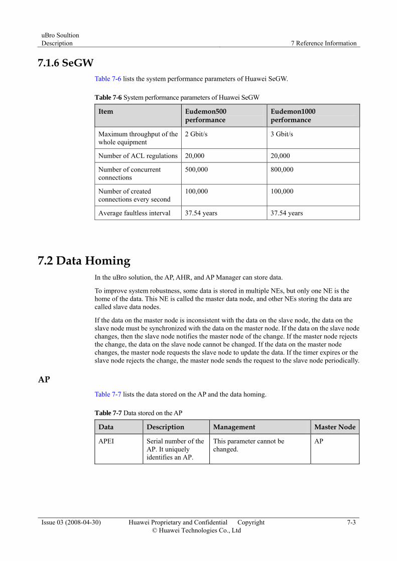
uBro Soultion Description 7 Reference Information
Issue 03 (2008-04-30) Huawei Proprietary and Confidential Copyright © Huawei Technologies Co., Ltd
7-3
7.1.6 SeGW Table 7-6 lists the system performance parameters of Huawei SeGW.
Table 7-6 System performance parameters of Huawei SeGW
Item Eudemon500 performance
Eudemon1000 performance
Maximum throughput of the whole equipment
2 Gbit/s 3 Gbit/s
Number of ACL regulations 20,000 20,000
Number of concurrent connections
500,000 800,000
Number of created connections every second
100,000 100,000
Average faultless interval 37.54 years 37.54 years
7.2 Data Homing In the uBro solution, the AP, AHR, and AP Manager can store data.
To improve system robustness, some data is stored in multiple NEs, but only one NE is the home of the data. This NE is called the master data node, and other NEs storing the data are called slave data nodes.
If the data on the master node is inconsistent with the data on the slave node, the data on the slave node must be synchronized with the data on the master node. If the data on the slave node changes, then the slave node notifies the master node of the change. If the master node rejects the change, the data on the slave node cannot be changed. If the data on the master node changes, the master node requests the slave node to update the data. If the timer expires or the slave node rejects the change, the master node sends the request to the slave node periodically.
AP Table 7-7 lists the data stored on the AP and the data homing.
Table 7-7 Data stored on the AP
Data Description Management Master Node
APEI Serial number of the AP. It uniquely identifies an AP.
This parameter cannot be changed.
AP

7 Reference Information uBro Soultion
Description
7-4 Huawei Proprietary and Confidential Copyright © Huawei Technologies Co., Ltd
Issue 03 (2008-04-30)
Data Description Management Master Node
Admission list Identifies that the UE is a valid user of the AP
The list is generated during program initialization and exists permanently.
The list can be viewed on the operation interface. The change of the list must be reported to the home server.
The list can be changed on the operation interface. The change takes effect only after being reported to the home server.
AHR
Function control parameters
Define the functions and specifications of the AP. Such parameters include admission policies, maximum resident users, and the types of Aps.
These parameters are generated during program initialization and exist permanently with the default values.
These parameters can be viewed on the operation interfaces of the AP Manager and AP.
These parameters are sent by the home server and cannot be updated by the AP.
AHR
Wireless configuration parameters
Used to configure the network, cell, and algorithm.
If these parameters are not configured on the AP, the default parameters on the AP are used.
After downloading these parameters from the AP Manager, the AP stores and uses the parameter configuration.
AHR
Transmission configuration parameters
Transmission security parameter configuration of the AP. Used to record the security parameter configuration of each AP.
These parameters are obtained from the AHR and exist forever.
These parameters can be viewed on the operation interfaces of the AP Manager and AP.
The AP can request updated parameters from the AHR and the AHR can also send updated parameters to the AP on initiative.
AHR
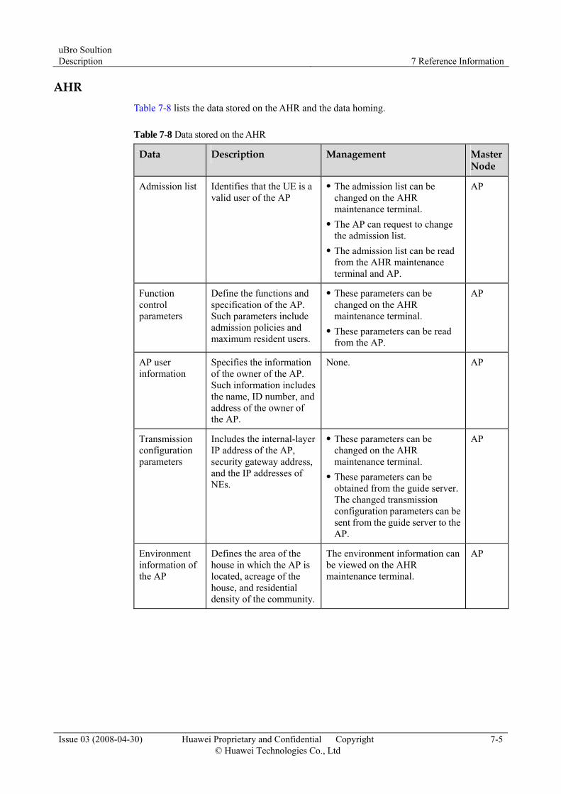
uBro Soultion Description 7 Reference Information
Issue 03 (2008-04-30) Huawei Proprietary and Confidential Copyright © Huawei Technologies Co., Ltd
7-5
AHR Table 7-8 lists the data stored on the AHR and the data homing.
Table 7-8 Data stored on the AHR
Data Description Management Master Node
Admission list Identifies that the UE is a valid user of the AP
The admission list can be changed on the AHR maintenance terminal.
The AP can request to change the admission list.
The admission list can be read from the AHR maintenance terminal and AP.
AP
Function control parameters
Define the functions and specification of the AP. Such parameters include admission policies and maximum resident users.
These parameters can be changed on the AHR maintenance terminal.
These parameters can be read from the AP.
AP
AP user information
Specifies the information of the owner of the AP. Such information includes the name, ID number, and address of the owner of the AP.
None. AP
Transmission configuration parameters
Includes the internal-layer IP address of the AP, security gateway address, and the IP addresses of NEs.
These parameters can be changed on the AHR maintenance terminal.
These parameters can be obtained from the guide server. The changed transmission configuration parameters can be sent from the guide server to the AP.
AP
Environment information of the AP
Defines the area of the house in which the AP is located, acreage of the house, and residential density of the community.
The environment information can be viewed on the AHR maintenance terminal.
AP
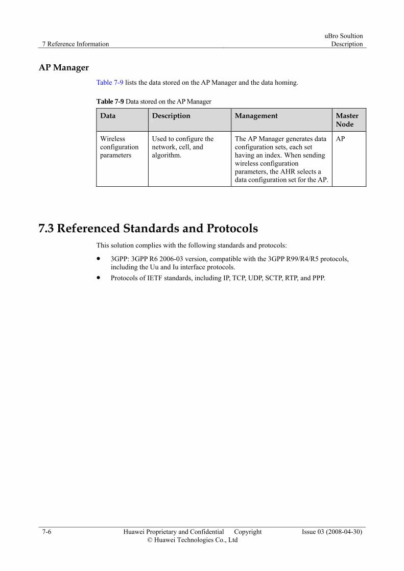
7 Reference Information uBro Soultion
Description
7-6 Huawei Proprietary and Confidential Copyright © Huawei Technologies Co., Ltd
Issue 03 (2008-04-30)
AP Manager Table 7-9 lists the data stored on the AP Manager and the data homing.
Table 7-9 Data stored on the AP Manager
Data Description Management Master Node
Wireless configuration parameters
Used to configure the network, cell, and algorithm.
The AP Manager generates data configuration sets, each set having an index. When sending wireless configuration parameters, the AHR selects a data configuration set for the AP.
AP
7.3 Referenced Standards and Protocols This solution complies with the following standards and protocols:
3GPP: 3GPP R6 2006-03 version, compatible with the 3GPP R99/R4/R5 protocols, including the Uu and Iu interface protocols.
Protocols of IETF standards, including IP, TCP, UDP, SCTP, RTP, and PPP.