Embed Size (px)
Citation preview

u-blox Wireless Modules Data and Voice Modules AT Commands Manual
Abstract
Description of standard and proprietary AT Commands used with
u-blox Wireless Modules.
.
www.u-blox.com
loca
te,
com
mu
nic
ate
, acc
ele
rate

u-blox Wireless Modules - AT Commands Manual
WLS-SW-11000-CP1
Page 2 of 448
Document Information
Title u-blox Wireless Modules
Subtitle Data and Voice Modules
Document type AT Commands Manual
Document number WLS-SW-11000-CP1
Document status Objective Specification
Document status information
Objective
Specification
This document contains target values. Revised and supplementary data will be published
later.
Advance
Information
This document contains data based on early testing. Revised and supplementary data will
be published later.
Preliminary This document contains data from product verification. Revised and supplementary data
may be published later.
Released This document contains the final product specification.
This document applies to the following products:
Name Type number Firmware version PCN reference
LEON-G100 LEON-G100-04S-00
LEON-G100-05S-00
LEON-G100-06S-00
LEON-G100-06S-01
LEON-G100-06A-00
LEON-G100-07S-00
LEON-G100-07A-00
07.40.01
07.50.00
07.60.00
07.60.02
07.60.00
07.70
07.70
GSM.G1-SW-10007
GSM.G1-SW-10008
GSM.G1-SW-10012
GSM.G1-SW-10013
GSM.G1-SW-10012
GSM.G1-SW-12002
GSM.G1-SW-12002
LEON-G200 LEON-G200-04S-00
LEON-G200-05S-00
LEON-G200-06S-00
LEON-G200-06S-01
07.40.02
07.50.00
07.60.00
07.60.02
GSM.G1-SW-10007
GSM.G1-SW-10008
GSM.G1-SW-10012
GSM.G1-SW-10013
SARA-G350 SARA-G350-00S-00
SARA-G350-51S-00
08.30
08.30
TBD
TBD
LISA-U100 LISA-U100-00S-00
LISA-U100-01S-00
10.72
11.40
UBX-TN-12031
UBX-TN-12008
LISA-U110 LISA-U110-00S-00
LISA-U110-01S-00
LISA-U110-60S-00
10.72
11.40
11.43
UBX-TN-12031
UBX-TN-12008
UBX-TN-12050
LISA-U120 LISA-U120-00S-00
LISA-U120-01S-00
10.72
11.40
UBX-TN-12031
UBX-TN-12008
LISA-U130 LISA-U130-00S-00
LISA-U130-01S-00
LISA-U130-60S-00
10.72
11.40
11.43
UBX-TN-12031
UBX-TN-12008
UBX-TN-12050
LISA-U200 LISA-U200-00S-00
LISA-U200-01S-00
21.21
22.40
UBX-TN-12009
UBX-TN-12040

u-blox Wireless Modules - AT Commands Manual
WLS-SW-11000-CP1
Page 3 of 448
Name Type number Firmware version PCN reference
LISA-U230 LISA-U230-01S-00 22.40 UBX-TN-12040
LISA-U260 LISA-U260-01S-00 22.60 UBX-TN-12060
LISA-U270 LISA-U270-01S-00 22.60 UBX-TN-12060
This document and the use of any information contained therein, is subject to the acceptance of the u-blox terms and conditions. They can be downloaded from www.u-blox.com.
u-blox makes no warranties based on the accuracy or completeness of the contents of this document and reserves the right to make changes
to specifications and product descriptions at any time without notice.
u-blox reserves all rights to this document and the information contained herein. Reproduction, use or disclosure to third parties without
express permission is strictly prohibited. Copyright © 2012, u-blox AG.
u-blox® is a registered trademark of u-blox Holding AG in the EU and other countries.

u-blox Wireless Modules - AT Commands Manual
WLS-SW-11000-CP1 Objective Specification Preface
Page 4 of 448
Preface u-blox Technical Documentation As part of our commitment to customer support, u-blox maintains an extensive volume of technical
documentation for our products. In addition to our product-specific technical data sheets, the following manuals
are available to assist u-blox customers in product design and development.
AT Commands Manual: This document provides the description of the supported AT commands by Wireless
Modules to verify all implemented functionalities.
System Integration Manual: This Manual provides hardware design instructions and information on how to set up production and final product tests.
How to use this Manual The u-blox Wireless Modules AT Commands Manual provides the necessary information to successfully design in and configure these u-blox wireless modules. For navigating this document, note the following:
This manual has a modular structure. It is not necessary to read it from the beginning to the end.
The following symbols are used to highlight important information within the manual:
An index finger points out key information pertaining to module integration and performance.
A warning symbol indicates actions that could negatively impact or damage the module.
Questions If you have any questions about u-blox Wireless Hardware Integration:
Read this manual carefully
Contact our information service on our homepage http://www.u-blox.com
Read the questions and answers on our FAQ database
Technical Support
Worldwide Web
Our website (www.u-blox.com) is a rich pool of information. Product information, technical documents and
helpful FAQ can be accessed 24h a day.
By E-mail
If you have technical problems or cannot find the required information in the provided documents, contact the
nearest of the Technical Support offices by email. Use our service pool email addresses rather than any personal email address of our staff. This makes sure that your request is processed as soon as possible. You will find the
contact details at the end of the document.
Helpful Information when Contacting Technical Support
When contacting Technical Support, have the following information ready:
Module type (e.g. LEON-G100-00S-01) and firmware version (e.g. 07.30)
Module configuration
Clear description of your question or the problem
A short description of the application
Your complete contact details

u-blox Wireless Modules - AT Commands Manual
WLS-SW-11000-CP1 Objective Specification Contents
Page 5 of 448
Contents
Preface ................................................................................................................................ 4
Contents .............................................................................................................................. 5
1 AT command settings ................................................................................................ 16
1.1 Definitions .......................................................................................................................................... 16
1.2 Profiles ............................................................................................................................................... 19
1.3 S-parameters ...................................................................................................................................... 19
2 General operation ...................................................................................................... 20
2.1 Start up and initialization .................................................................................................................... 20
2.2 AT Commands mode .......................................................................................................................... 20
3 IPC – Inter Processor Communication ........................................................................ 21
3.1 Multiplexing mode +CMUX ................................................................................................................ 21
4 General ........................................................................................................................ 23
4.1 Manufacturer identification +CGMI .................................................................................................... 23
4.2 Request model identification +CGMM ................................................................................................ 23
4.3 Request Firmware version +CGMR ...................................................................................................... 23
4.4 Request for IMEI +CGSN ..................................................................................................................... 24
4.5 Set TE character set +CSCS ................................................................................................................. 24
4.6 Request international mobile subscriber identification +CIMI .............................................................. 25
4.7 Card identification +CCID ................................................................................................................... 25
4.8 Request complete capabilities list +GCAP ........................................................................................... 26
4.9 Repeat last command A/ ..................................................................................................................... 26
5 Mobile equipment control and status ...................................................................... 27
5.1 Phone activity status +CPAS ............................................................................................................... 27
5.2 Switch off MT +CPWROFF .................................................................................................................. 27
5.3 Set phone functionality +CFUN ........................................................................................................... 28
5.4 Battery charge +CBC .......................................................................................................................... 29
5.5 Indicator control +CIND ...................................................................................................................... 30
5.6 Mobile termination event reporting +CMER........................................................................................ 31
5.7 Clock +CCLK ...................................................................................................................................... 34
5.8 Alarm +CALA ..................................................................................................................................... 34
5.9 Delete alarm +CALD ........................................................................................................................... 35
5.10 Restricted SIM access +CRSM .......................................................................................................... 36
5.11 Alert sound mode +CALM .............................................................................................................. 37
5.12 Ringer sound level +CRSL ................................................................................................................ 38
5.13 Loudspeaker volume level +CLVL .................................................................................................... 38
5.14 Mute control +CMUT ...................................................................................................................... 39

u-blox Wireless Modules - AT Commands Manual
WLS-SW-11000-CP1 Objective Specification Contents
Page 6 of 448
5.15 Call meter maximum event +CCWE ................................................................................................ 40
5.16 Set greeting text +CSGT ................................................................................................................. 40
5.17 Automatic Time Zone Update +CTZU .............................................................................................. 41
5.18 Time Zone Reporting +CTZR ........................................................................................................... 41
5.19 Report mobile termination error +CMEE ......................................................................................... 42
5.20 List all available AT commands +CLAC ............................................................................................ 43
6 Call control .................................................................................................................. 44
6.1 Select type of address +CSTA ............................................................................................................. 44
6.2 Dial command D ................................................................................................................................. 44
6.3 Direct calling from phonebooks D> .................................................................................................... 46
6.4 Select tone dialling T........................................................................................................................... 47
6.5 Select pulse dialling P.......................................................................................................................... 47
6.6 Call answer A ..................................................................................................................................... 47
6.7 Hook control H ................................................................................................................................... 48
6.8 Monitor speaker loudness L ................................................................................................................ 48
6.9 Monitor speaker mode M ................................................................................................................... 48
6.10 Call mode +CMOD ......................................................................................................................... 49
6.11 Hang up call +CHUP ....................................................................................................................... 49
6.12 Extended error report +CEER .......................................................................................................... 50
6.13 Single numbering scheme +CSNS ................................................................................................... 51
6.14 Tone duration +VTD ....................................................................................................................... 51
6.15 DTMF and tone generation +VTS .................................................................................................... 52
6.16 Redial last telephone number DL ..................................................................................................... 53
6.17 Automatic answer S0 ...................................................................................................................... 53
6.18 Set Voice Mail Number +CSVM ....................................................................................................... 53
7 Network service.......................................................................................................... 55
7.1 Subscriber number +CNUM ................................................................................................................ 55
7.2 Signal quality +CSQ ............................................................................................................................ 55
7.3 Operator selection +COPS .................................................................................................................. 56
7.4 Network registration +CREG ............................................................................................................... 59
7.5 Preferred operator list +CPOL ............................................................................................................. 61
7.6 Read operator names +COPN ............................................................................................................. 62
7.7 User to user signalling service 1 +CUUS1 ............................................................................................ 62
8 Security ....................................................................................................................... 65
8.1 Enter PIN +CPIN .................................................................................................................................. 65
8.2 Facility lock +CLCK ............................................................................................................................. 66
8.3 Change password +CPWD ................................................................................................................. 67
9 Phonebook .................................................................................................................. 68
9.1 Select phonebook memory storage +CPBS ......................................................................................... 68
9.2 Read phonebook entries +CPBR ......................................................................................................... 68
9.3 Find phonebook entries +CPBF ........................................................................................................... 70
u-blox Wireless Modules - AT Commands Manual
WLS-SW-11000-CP1 Objective Specification Contents
Page 7 of 448
9.4 Write phonebook entry +CPBW .......................................................................................................... 71
10 Short Messages Service ............................................................................................. 73
10.1 Introduction .................................................................................................................................... 73
10.2 Select message service +CSMS ........................................................................................................ 73
10.3 Preferred message storage +CPMS .................................................................................................. 74
10.4 Preferred message format +CMGF .................................................................................................. 75
10.5 Save settings +CSAS ....................................................................................................................... 76
10.6 Restore Settings +CRES ................................................................................................................... 76
10.7 Show text mode parameters +CSDH ............................................................................................... 76
10.8 New message indication +CNMI ..................................................................................................... 77
10.9 Read message +CMGR ................................................................................................................... 80
10.10 New Message Acknowledgement to MT +CNMA ........................................................................... 83
10.11 List message +CMGL....................................................................................................................... 83
10.12 Send message +CMGS .................................................................................................................... 86
10.13 Write message to memory +CMGW ............................................................................................... 87
10.14 Send message from storage +CMSS ................................................................................................ 88
10.15 Set text mode parameters +CSMP ................................................................................................... 89
10.16 Delete SMS +CMGD ....................................................................................................................... 89
10.17 Service center address +CSCA ......................................................................................................... 90
10.18 Select cell broadcast message types +CSCB .................................................................................... 91
10.19 Read concatenated message +UCMGR ........................................................................................... 91
10.20 List concatenated message +UCMGL .............................................................................................. 94
10.21 Send concatenated message +UCMGS ........................................................................................... 97
10.22 Write concatenated message to memory +UCMGW ....................................................................... 98
10.23 More Messages to Send +CMMS .................................................................................................... 99
10.24 Peek message +UCMGP .................................................................................................................. 99
11 Supplementary services ........................................................................................... 101
11.1 Call forwarding +CCFC ................................................................................................................. 101
11.2 Call waiting +CCWA ..................................................................................................................... 102
11.3 Calling line identification restriction +CLIR .................................................................................... 104
11.4 Calling line identification presentation +CLIP ................................................................................ 104
11.5 Connected line identification presentation +COLP ........................................................................ 105
11.6 Connected line identification restriction +COLR ............................................................................ 106
11.7 Advise of charge +CAOC .............................................................................................................. 107
11.8 Accumulated call meter +CACM ................................................................................................... 107
11.9 Accumulated call meter maximum +CAMM .................................................................................. 108
11.10 Price per unit and currency table +CPUC ....................................................................................... 108
11.11 Call related supplementary services +CHLD ................................................................................... 109
11.12 Call deflection +CTFR .................................................................................................................... 109
11.13 List current calls +CLCC ................................................................................................................ 110
11.14 Supplementary service notifications +CSSN ................................................................................... 111
11.15 Unstructured supplementary service data +CUSD .......................................................................... 112
11.16 Closed user group +CCUG ............................................................................................................ 113

u-blox Wireless Modules - AT Commands Manual
WLS-SW-11000-CP1 Objective Specification Contents
Page 8 of 448
11.17 Calling name presentation +CNAP ................................................................................................ 114
12 Data ........................................................................................................................... 115
12.1 Select bearer service type +CBST ................................................................................................... 115
12.2 Service class selection and identification +FCLASS ......................................................................... 116
12.3 Service reporting control +CR ....................................................................................................... 117
12.4 Cellular result codes +CRC ............................................................................................................ 118
12.5 Radio link protocol +CRLP ............................................................................................................. 118
13 FAX class 2 ................................................................................................................ 120
13.1 Introduction .................................................................................................................................. 120
13.2 Adaptive answer +FAA ................................................................................................................. 120
13.3 Address & polling capabilities +FAP ............................................................................................... 120
13.4 Buffer size +FBS ............................................................................................................................ 121
13.5 Data bit order +FBO ...................................................................................................................... 121
13.6 HDLC frame reporting +FBU ......................................................................................................... 122
13.7 DS capabilities parameters +FCC ................................................................................................... 122
13.8 Copy quality checking +FCQ ......................................................................................................... 123
13.9 Capability to receive data +FCR ..................................................................................................... 123
13.10 Current session results +FCS ......................................................................................................... 124
13.11 DTE phase C response timeout +FCT............................................................................................. 124
13.12 Receive data +FDR ........................................................................................................................ 124
13.13 Transmit Data +FDT ...................................................................................................................... 125
13.14 Phase C received EOL alignment +FEA .......................................................................................... 125
13.15 Format conversion +FFC ................................................................................................................ 125
13.16 Report file transfer diagnostic frame +FFD..................................................................................... 126
13.17 Call termination status +FHS ......................................................................................................... 126
13.18 Procedure interrupt enable +FIE .................................................................................................... 127
13.19 Initialize facsimile parameters +FIP ................................................................................................ 127
13.20 Current session parameters +FIS ................................................................................................... 128
13.21 Inactivity timeout +FIT ................................................................................................................... 129
13.22 Session termination +FKS, +FK ...................................................................................................... 129
13.23 Local ID string +FLI ........................................................................................................................ 129
13.24 Set flow control +FLO ................................................................................................................... 130
13.25 Indicate document to poll +FLP ..................................................................................................... 130
13.26 Request manufacturer Identification +FMI ..................................................................................... 130
13.27 Request model identification +FMM .............................................................................................. 131
13.28 Request revision identification +FMR ............................................................................................. 131
13.29 Minimum phase C speed +FMS ..................................................................................................... 131
13.30 Negotiation reporting +FNR .......................................................................................................... 132
13.31 Non-standard frame FIF octet string +FNS ..................................................................................... 132
13.32 NSF message data indication +FND ............................................................................................... 133
13.33 Selective polling address +FPA ...................................................................................................... 133
13.34 Local polling ID string +FPI ............................................................................................................ 134
13.35 Packet protocol control +FPP ......................................................................................................... 134

u-blox Wireless Modules - AT Commands Manual
WLS-SW-11000-CP1 Objective Specification Contents
Page 9 of 448
13.36 Page status +FPS ........................................................................................................................... 134
13.37 Password parameter +FPW ........................................................................................................... 135
13.38 Receive quality thresholds +FRQ .................................................................................................... 135
13.39 Error correction mode retry count +FRY ........................................................................................ 136
13.40 SubAddress parameter +FSA ......................................................................................................... 136
13.41 Request to poll +FSP ..................................................................................................................... 136
13.42 Fax intermediate result codes ........................................................................................................ 137
14 V24 control and V25ter ............................................................................................ 138
14.1 Reset to default configuration Z .................................................................................................... 138
14.2 Set to factory defined configuration &F ......................................................................................... 138
14.3 Circuit 109 behavior &C ................................................................................................................ 139
14.4 Circuit 108/2 behavior &D ............................................................................................................. 139
14.5 DSR override &S ............................................................................................................................ 141
14.6 Flow control &K ............................................................................................................................ 141
14.7 Store current configuration &W .................................................................................................... 142
14.8 Display current configuration &V................................................................................................... 142
14.9 Designate a default reset profile &Y .............................................................................................. 143
14.10 Request identification information I............................................................................................... 143
14.11 Request manufacturer Identification +GMI .................................................................................... 144
14.12 Request model identification +GMM............................................................................................. 144
14.13 Request revision identification +GMR ............................................................................................ 144
14.14 Request product serial number identification +GSN ...................................................................... 145
14.15 DTE-DCE character framing +ICF ................................................................................................... 145
14.16 DTE-DCE local flow control +IFC ................................................................................................... 146
14.17 Set flow control \Q ........................................................................................................................ 147
14.18 Fixed DTE rate +IPR ....................................................................................................................... 148
14.19 System can Return to on-line data state O .................................................................................... 151
14.20 Escape character S2 ...................................................................................................................... 151
14.21 Command line termination character S3 ....................................................................................... 152
14.22 Response formatting character S4 ................................................................................................. 152
14.23 Command line editing character S5 .............................................................................................. 153
14.24 Pause before blind dialling S6 ....................................................................................................... 153
14.25 Connection completion timeout S7 ............................................................................................... 154
14.26 Command dial modifier time S8 .................................................................................................... 154
14.27 Automatic disconnect delay S10 ................................................................................................... 155
14.28 Escape prompt delay (EPD) S12 ..................................................................................................... 155
14.29 Command echo E ......................................................................................................................... 156
14.30 Result code suppression Q ............................................................................................................ 156
14.31 DCE response format V ................................................................................................................. 157
14.32 Result code selection and call progress monitoring control X ........................................................ 157
15 SIM toolkit ................................................................................................................ 158
15.1 Introduction .................................................................................................................................. 158
15.2 Proactive command +STKPRO ....................................................................................................... 158

u-blox Wireless Modules - AT Commands Manual
WLS-SW-11000-CP1 Objective Specification Contents
Page 10 of 448
15.3 Terminal response +STKTR ............................................................................................................ 161
15.4 Envelope +STKENV........................................................................................................................ 163
15.5 Terminal profile +STKPROF ............................................................................................................ 164
15.6 Call and short message control URC +STKCC ............................................................................... 165
15.7 Proactive session status URC +STKCNF .......................................................................................... 166
15.8 Raw Mode Envelope Download +SATE ......................................................................................... 166
15.9 Proactive Command Indication in RAW Mode +SATI ..................................................................... 167
15.10 Proactive Command Indication in RAW Mode +SATN ................................................................... 167
15.11 Send Terminal Response in RAW Mode +SATR ............................................................................. 168
15.12 Terminal Response Confirm +SATF ................................................................................................ 168
15.13 User confirmation for SET UP Call in RAW mode +SATD ............................................................... 170
15.14 Indication for Mo Call Control / Mo SMS Control +STKCTRLIND ................................................... 170
16 GPRS/PSD .................................................................................................................. 172
16.1 Parameters definition .................................................................................................................... 172
16.2 Define PDP context +CGDCONT ................................................................................................... 178
16.3 Quality of service profile (requested) +CGQREQ ............................................................................ 179
16.4 Quality of service profile (minimum acceptable) +CGQMIN ........................................................... 180
16.5 GPRS attach or detach +CGATT .................................................................................................... 180
16.6 PDP context activate or deactivate +CGACT .................................................................................. 181
16.7 Enter data state +CGDATA ........................................................................................................... 183
16.8 Enter IP state/GPRS IP dial D .......................................................................................................... 185
16.9 Show PDP address +CGPADDR ..................................................................................................... 185
16.10 GPRS mobile station class +CGCLASS ........................................................................................... 185
16.11 GPRS event reporting +CGEREP .................................................................................................... 186
16.12 GPRS network registration status +CGREG ................................................................................... 188
16.13 Select service for MO SMS messages +CGSMS .............................................................................. 189
16.14 Manual deactivation of a PDP context H ....................................................................................... 189
16.15 PDP Context Modify +CGCMOD ................................................................................................... 190
16.16 3G Quality of service profile (requested) +CGEQREQ ..................................................................... 190
16.17 3G Quality of service profile (minimum acceptable) +CGEQMIN .................................................... 192
16.18 3G Quality of Service Profile (negotiated) +CGEQNEG ................................................................... 194
16.19 Define Secondary PDP context +CGDSCONT ................................................................................. 195
16.20 Traffic Flow Template +CGTFT ...................................................................................................... 196
16.21 Multiple PDP contexts ................................................................................................................... 197
16.22 Primary and secondary PDP contexts ............................................................................................. 198
17 Specific ...................................................................................................................... 199
17.1 FOTA configuration +UFOTA ......................................................................................................... 199
17.2 Firmware Update over AT command (FOAT) +UFWUPD ................................................................ 200
17.3 Antenna Detection +UANTR ......................................................................................................... 202
17.4 ADC read command +UADC ........................................................................................................ 203
17.5 Power saving control (Power SaVing) +UPSV ................................................................................. 203
17.6 Tone generator (Tone GeNerator) +UTGN ..................................................................................... 205
17.7 Ringing tone selection command +URNG ..................................................................................... 206

u-blox Wireless Modules - AT Commands Manual
WLS-SW-11000-CP1 Objective Specification Contents
Page 11 of 448
17.8 SMS Alert sound mode (Message Sound Muting) +UMSM ............................................................ 206
17.9 I2S Digital Interface Mode +UI2S .................................................................................................... 207
17.10 Audio Path mode setting (Set Path Mode) +USPM ........................................................................ 215
17.11 Play audio resource (Play Audio Resource) +UPAR ......................................................................... 218
17.12 Stop audio resource (Stop Audio Resource) +USAR ....................................................................... 220
17.13 Play audio file +UPLAYFILE ............................................................................................................ 220
17.14 Stop AMR audio file +USTOPFILE .................................................................................................. 221
17.15 Jamming Detection +UCD ............................................................................................................. 222
17.16 Select Band +UBANDSEL ............................................................................................................... 224
17.17 Set reporting call status +UCALLSTAT ........................................................................................... 225
17.18 Display operator name +UDOPN ................................................................................................... 226
17.19 Device configuration +UDCONF .................................................................................................... 227
17.20 Display EONS names +UEONS ....................................................................................................... 233
17.21 PS Operator selection +UCGOPS ................................................................................................... 234
17.22 Cell environment description +CGED ............................................................................................ 235
17.23 Device class setting +UCLASS ........................................................................................................ 245
17.24 Read counters of sent or received PSD data +UGCNTRD ............................................................... 247
17.25 Set/reset counter of sent or received PSD data +UGCNTSET .......................................................... 248
17.26 Read remaining SIM PIN attempts +UPINCNT ................................................................................ 248
17.27 Help displaying all commands &H ................................................................................................. 249
17.28 Provide Cell information +UCELLINFO ........................................................................................... 249
17.29 Configuration of Indicator control +UCIND ................................................................................... 251
17.30 Customer service profile +UCSP .................................................................................................... 251
17.31 User setting for proactive DTMF tone generation +UDTMF............................................................ 252
17.32 Changing the startup MS class +UCGCLASS ................................................................................. 252
17.33 Generic SIM access +CSIM ............................................................................................................ 253
17.34 Selection of preferred PLMN list +CPLS ......................................................................................... 253
17.35 Read the SIM language +CLAN ..................................................................................................... 254
17.36 Check for UICC card +UUICC ....................................................................................................... 254
17.37 Home zone reporting +UHOMEZR ................................................................................................ 255
17.38 Configure the mode of HSDPA/HSUPA +UHSDUPA ....................................................................... 255
17.39 Information to in-band-tones availability +UPROGRESS ................................................................. 256
17.40 Selection of Radio Access technology +URAT ................................................................................ 257
17.41 Extended Packet Switched network registration status +UREG ...................................................... 258
17.42 Start and stop tone generation +UVTS .......................................................................................... 259
17.43 PCCA STD-101 [17] select wireless network +WS46 ..................................................................... 260
17.44 End User Test +UTEST ................................................................................................................... 260
17.45 Smart temperature Supervisor +USTS ............................................................................................ 265
17.46 Configure the Data Channel +UDATACHANNEL ........................................................................... 266
17.47 Custom SIM Lock +USIMLCK ........................................................................................................ 267
17.48 Network Selection Control +PACSP ............................................................................................... 269
17.49 Rx Diversity +URXDIV .................................................................................................................... 270
17.50 Message Waiting Indication +UMWI ............................................................................................. 271
17.51 External Device Configuration +UEXTDCONF ................................................................................ 272

u-blox Wireless Modules - AT Commands Manual
WLS-SW-11000-CP1 Objective Specification Contents
Page 12 of 448
18 GPIO .......................................................................................................................... 274
18.1 Introduction .................................................................................................................................. 274
18.2 GPIO select configuration command +UGPIOC ............................................................................. 281
18.3 GPIO read command +UGPIOR ..................................................................................................... 282
18.4 GPIO set command +UGPIOW ...................................................................................................... 283
19 File System ................................................................................................................ 284
19.1 Download file +UDWNFILE ............................................................................................................ 284
19.2 Delete file +UDELFILE .................................................................................................................... 284
19.3 Read file +URDFILE ........................................................................................................................ 285
19.4 List files information +ULSTFILE ..................................................................................................... 285
19.5 Download file +URDBLOCK .......................................................................................................... 286
20 Audio parameters tuning ........................................................................................ 288
20.1 Introduction .................................................................................................................................. 288
20.2 Microphone Gain (Microphone Gain Control) +UMGC ................................................................. 291
20.3 Speaker Gain (Speaker Gain Control) +USGC ................................................................................ 292
20.4 Sidetone (SideToNe) +USTN .......................................................................................................... 294
20.5 Uplink Digital Filters (Uplink Biquad Filters) +UUBF ........................................................................ 295
20.6 Downlink Digital Filters (Downlink Biquad Filters) +UDBF ............................................................... 298
20.7 Hands-Free Parameters (Hands-Free Parameters) +UHFP ................................................................ 301
20.8 Master Clock Control +UMCLK ..................................................................................................... 309
21 Data Connection Setup ............................................................................................ 311
21.1 Packet Switched Data +UPSD ........................................................................................................ 311
21.2 Packet Switched Data Action +UPSDA .......................................................................................... 316
21.3 Packet Switched Network-assigned Data +UPSND ......................................................................... 316
21.4 Circuit Switched Data +UCSD ....................................................................................................... 317
21.5 Circuit Switched Data Action +UCSDA .......................................................................................... 318
21.6 Circuit Switched Network-assigned Data +UCSND ........................................................................ 319
22 DNS ............................................................................................................................ 320
22.1 Resolve Name / IP Number through DNS +UDNSRN ...................................................................... 320
23 TCP/IP UDP/IP ............................................................................................................ 321
23.1 Introduction .................................................................................................................................. 321
23.2 Create Socket +USOCR ................................................................................................................. 321
23.3 Set Socket Option +USOSO ........................................................................................................... 322
23.4 Get Socket Option +USOGO ......................................................................................................... 323
23.5 Close Socket +USOCL ................................................................................................................... 324
23.6 Get Socket Error +USOER .............................................................................................................. 324
23.7 Connect Socket +USOCO ............................................................................................................. 325
23.8 Write Socket Data +USOWR ......................................................................................................... 325
23.9 Send To command +USOST (UDP only) ......................................................................................... 327
23.10 Read Socket Data +USORD ........................................................................................................... 328
u-blox Wireless Modules - AT Commands Manual
WLS-SW-11000-CP1 Objective Specification Contents
Page 13 of 448
23.11 Receive From command +USORF (UDP only) ................................................................................. 330
23.12 Set Listening Socket +USOLI .......................................................................................................... 331
23.13 Firewall control +UFRW ................................................................................................................. 332
23.14 Set socket in Direct Link mode +USODL ........................................................................................ 333
23.15 Socket Control +USOCTL .............................................................................................................. 334
24 FTP ............................................................................................................................. 336
24.1 FTP Control +UFTP ........................................................................................................................ 336
24.2 FTP Command +UFTPC ................................................................................................................. 338
24.3 FTP Unsolicited Data URC +UUFTPCD............................................................................................ 340
24.4 FTP Command Result URC +UUFTPCR........................................................................................... 341
24.5 FTP Error +UFTPER......................................................................................................................... 341
25 HTTP .......................................................................................................................... 342
25.1 HTTP Control +UHTTP ................................................................................................................... 342
25.2 HTTP Command +UHTTPC ............................................................................................................ 343
25.3 HTTP Command Result URC +UUHTTPCR ..................................................................................... 345
25.4 HTTP Protocol Error +UHTTPER ...................................................................................................... 345
26 SMTP ......................................................................................................................... 347
26.1 SMTP Control +USMTP ................................................................................................................. 347
26.2 SMTP Mail Control +USMTPM ...................................................................................................... 348
26.3 SMTP Command +USMTPC .......................................................................................................... 350
26.4 SMTP Command Result URC +UUSMTPCR .................................................................................... 351
26.5 SMTP Error +USMTPER .................................................................................................................. 351
27 PING ........................................................................................................................... 352
27.1 Ping Command +UPING ................................................................................................................ 352
28 GPS ............................................................................................................................ 354
28.1 GPS Power Management +UGPS .................................................................................................. 354
28.2 Assisted GPS unsolicited indication +UGIND .................................................................................. 355
28.3 GPS Profile configuration +UGPRF ................................................................................................. 357
28.4 AssistNow Online configuration +UGAOP ..................................................................................... 358
28.5 AssistNow Offline configuration +UGAOF ..................................................................................... 359
28.6 GPS Aiding request command +UGAOS ....................................................................................... 360
28.7 Send of UBX string +UGUBX ......................................................................................................... 360
28.8 GPS Indications timer +UGTMR ..................................................................................................... 361
28.9 Get GPS Time and date +UGZDA .................................................................................................. 362
28.10 Get GPS fix data +UGGGA ............................................................................................................ 363
28.11 Get geographic position +UGGLL .................................................................................................. 363
28.12 Get number of GNSS satellites in view +UGGSV ........................................................................... 364
28.13 Get recommended minimum GNSS data +UGRMC ....................................................................... 365
28.14 Get course over ground and ground speed +UGVTG .................................................................... 366
28.15 Get satellite information +UGGSA ................................................................................................ 366

u-blox Wireless Modules - AT Commands Manual
WLS-SW-11000-CP1 Objective Specification Contents
Page 14 of 448
28.16 Ask for localization information +ULOC ........................................................................................ 367
28.17 Configure GNSS sensor +ULOCGNSS ............................................................................................ 369
28.18 Configure cellular location sensor (CellLocate) +ULOCCELL ........................................................... 371
29 In-Band Modem ........................................................................................................ 373
29.1 Introduction .................................................................................................................................. 373
29.2 InBM status +UIBMSTAT ............................................................................................................... 373
29.3 InBM sends and receives data +UIBMDATA ................................................................................... 375
29.4 eCall status +UECALLSTAT ............................................................................................................ 376
29.5 eCall type +UECALLTYPE .............................................................................................................. 376
30 I2C............................................................................................................................... 378
30.1 Introduction .................................................................................................................................. 378
30.2 I2C open logical channel +UI2CO .................................................................................................. 378
30.3 I2C write to peripheral +UI2CW ..................................................................................................... 379
30.4 I2C read from peripheral +UI2CR ................................................................................................... 380
30.5 I2C read from peripheral register +UI2CREGR ................................................................................ 380
30.6 I2C close logical channel +UI2CC ................................................................................................... 381
31 SAP ............................................................................................................................ 382
31.1 Introduction .................................................................................................................................. 382
31.2 SAP Mode activation +USAPMODE ............................................................................................... 382
31.3 SAP Mode indications +USAPIND .................................................................................................. 383
Appendix ........................................................................................................................ 385
A Appendix 1 ............................................................................................................... 385
A.1 Internet suite error classes ................................................................................................................ 385
A.1.1 FTP class error codes ..................................................................................................................... 385
A.1.2 HTTP class error codes ................................................................................................................... 388
A.1.3 SMTP class error codes .................................................................................................................. 389
A.1.4 File System Class Error codes ......................................................................................................... 389
A.2 Ping error codes ................................................................................................................................ 391
A.3 Internal TCP/UDP/IP stack class error codes ....................................................................................... 391
A.4 FOAT Error Messages ........................................................................................................................ 394
A.5 FOTA Error codes .............................................................................................................................. 394
A.5.1 FOTA class - UA errors .................................................................................................................. 394
A.5.2 FOTA class - Data Connection errors ............................................................................................. 396
A.5.3 FOTA class - SMS Errors ................................................................................................................ 396
A.5.4 FOTA class - HTTP errors ............................................................................................................... 397
A.6 Mobile Termination error result codes +CME ERROR ........................................................................ 397
A.7 Message service failure result codes +CMS ERROR ............................................................................ 403
A.8 +CEER error codes ............................................................................................................................ 405
B AT Commands List .................................................................................................... 413

u-blox Wireless Modules - AT Commands Manual
WLS-SW-11000-CP1 Objective Specification Contents
Page 15 of 448
B.1 Parameters stored in profiles ............................................................................................................. 426
B.2 Parameters stored in non volatile memory ........................................................................................ 432
B.3 Saving AT commands configuration .................................................................................................. 436
B.4 Estimated command response time .................................................................................................. 436
B.5 Multiple AT command interfaces ...................................................................................................... 437
C UDP Direct Link workflow ....................................................................................... 438
C.1 Data from the IP network to the external port .................................................................................. 438
C.2 Data from the external port to the IP network .................................................................................. 438
D Glossary .................................................................................................................... 440
Related documents......................................................................................................... 444
Revision history .............................................................................................................. 447
Contact ............................................................................................................................ 448

u-blox Wireless Modules - AT Commands Manual
WLS-SW-11000-CP1 Objective Specification AT command settings
Page 16 of 448
1 AT command settings u-blox Wireless Modules provide at least a physical serial interface (UART) compliant to V.24ter which starts in
the command mode. For more details on command mode, refer to chapter 1.1.
For module and hyper terminal connection and settings see EVK-G25H Evaluation Kit Getting Started [43] or
EVK-U12 EVK-U13 Getting Started [48] or EVK-G20 Evaluation Kit Getting Started [55] or EVK-U20 EVK-U23
Getting Started [68], EVK-G35 Evaluation Kit Getting Started [73].
1.1 Definitions
In this document the following naming conventions are used:
DCE (Data Communications Equipment) or MT (Mobile Terminal): u-blox wireless module
TE (Terminal Equipment) or DTE (Data Terminal Equipment): terminal that sends the command to the
module
The terms DCE and DTE are used in the serial interface context.
u-blox Wireless Modules implement more than one interface between DTE and DCE, either virtual interfaces
(multiplexer channels) or physical interfaces (UART, USB, SPI, etc., when available). Each interface works as specified by the followings definitions. If not differently stated, all the subsequent descriptions are applicable to
every interface.
The differences among the interfaces in reference to the AT command interface are presented in the Appendix B.5.
The DCE interface can operate in two different modes:
Command mode: the DCE waits for AT command instructions. Any characters sent to the DCE are
interpreted as commands for the DCE to execute. The DCE may send responses back to the DTE indicating
the outcome of the command or further information without having received any commands by the DTE (e.g. unsolicited response code - URC). Any communication in command mode (in either direction) is
terminated by the command line termination character
Data mode: the DCE transfers data after having sent the “CONNECT” string; any character sent to the DCE is intended to be transmitted to the remote party. Any further characters received over the serial link are
deemed to be from the remote party, and any characters sent are transmitted to the remote party. The DCE
enters data mode immediately after it makes a CSD or PSD connection
Online command mode: the DCE is communicating with a remote party, but treats signals from the DTE
on TxD as command lines and sends responses to the DTE on RxD
It is possible to switch between data and online command mode (when a data connection is established) in the following ways:
with the escape sequence: for more details, refer to chapter 14.20
via a DTR ON to OFF transition: for more details, refer to the table in chapter 14.4.4
To switch back to data mode from online command mode ATO command is used. For more details, refer to O command (chapter 14.19) and &D command (chapter 14.4).

u-blox Wireless Modules - AT Commands Manual
WLS-SW-11000-CP1 Objective Specification AT command settings
Page 17 of 448
1.1.1 Command description
AT commands configure and enable the wireless module functionalities in accordance to 3GPP normative and
u-blox specifications. AT commands are provided to the module via a hyper terminal through a command line
and are described in the following chapters. A general description of each command is provided including functionalities, correct syntax to be provided by the TE/DTE, possible responses, and an example. The command
description defines each named parameter with its type, its range (valid / acceptable values), the default value
(when available) and the factory-programmed setting (when applicable).
The commands that apply to each u-blox wireless module are listed in the chapter B.
The example provided in the command description refers only to the handling provided by the command. It could be applied only to a product not to all products which the document is applied to.
The list of allowed values for a specific product is provided in the corresponding Defined values chapter.
In this document <CR><LF> are intentionally omitted.
If a parameter is omitted, no value will be inserted between the two commas indicating the interested parameter in the command line sent by the DTE.
The following rules are used when describing the command syntax:
<…>: Name in angle brackets is a parameter. The brackets themselves do not appear in the command line
[…]: the square brackets represent the optional parameters of a command or an optional part of the TA
information response. Brackets themselves do not appear in the command line. When parameter is not
given, the value will be set to the default value provided in the command description
1.1.2 Default values
If the command parameters are optional, they can be left out in the command line. If not otherwise specified, the default values are assumed as follows
In case of Number type parameters, the default value is 0
In case of String type parameters, the default value is an empty string
1.1.3 Command line
AT commands are typically provided to wireless modules using a command line with the following generic
syntax:
“AT”<command_name><string><S3_character>
Where:
“AT”: prefix to be set at the beginning of each command line
<command_name>: command name string; it can have a ‘+’ character as prefix
<string>: string consisting of the value parameters following the syntax provided in this manual
<S3_character>: Command line termination character; it can be set with ATS3 command; the factory-
programmed termination character is <CR> (for more details refer to chapter 14.21)
The maximum number of characters which can be accepted on a single command line is 512. The DTE
(used to send the characters) may further limit this numbers.
The command line is not case sensitive except the following case: if autobauding is enabled then the
attention mark “AT” must be typed either as “AT” or “at”; other combinations (e.g “At”) are not allowed.
When writing or sending an SMS, CtrlZ or ESC terminates the command; <CR> is used between the 2
parts of the SMS (address and text).
u-blox Wireless Modules - AT Commands Manual
WLS-SW-11000-CP1 Objective Specification AT command settings
Page 18 of 448
More than one AT command can be entered on the same command line. The "AT" prefix must be provided only at the beginning of the command line. Each command must be separated by using a semicolon as delimiter only
if the command has a ‘+’ character as prefix.
Example: AT&VE1;+CMGF?;+COPS?<CR>
In case a command in the command line causes an error, or is not recognized as a valid command, the execution
is terminated, the remaining commands in the command line are ignored and an ERROR result code is returned.
If all commands are correctly executed, only the OK result code of the last command is returned.
Not all commands can be entered with other commands on the same command line: +CMGW, +CMGS,
+USOWR, +USOST, + UDWNFILE must be used by themselves.
1.1.4 Information responses and result codes
The response format can be set with ATV command (for more details refer to the command description, section 0). The factory default setting (ATV1) is as follows:
Information responses: <S3_character><S4_character><text><S3_character><S4_character>
Result codes: <S3_character><S4_character><verbose code><S3_character><S4_character>
where
<S3_character>: Command line termination character; it can be set with S3 command (for more details refer
to chapter 14.21)
<S4_character> is the linefeed character, with value specified by command S4 (for more details refer to
chapter 14.22)
If the command line is performed successfully, the string “OK” is sent.
If the command is not accepted by the MT an error message will be displayed. The format of the error message
can be set with AT+CMEE command (see the command description form more details). In this manual it is assumed that AT+CMEE=2 and thus the error message is displayed with the format:
+CMS ERROR: <err>
if it is the response to a SMS related AT command, and with the format:
+CME ERROR: <err>
If it is the response to any other AT command.
where <err> represents the verbose result code.
The most typical errors are listed as follows:
If the command is not supported or unknown, either “+CME ERROR: unknown” or “+CME ERROR: operation not supported” is sent
If the command syntax is wrong, “+CME ERROR: operation not supported” is sent (“+CMS ERROR:
operation not supported” for SMS related commands)
The list of all allowed errors is available in Appendix A.6 and A.7. For some commands only the message
“ERROR” is displayed and is documented in the command description.
A different procedure will be followed for the following operations:
o FTP, HTTP, SMTP, TCP, UDP connection
o PING operation
o Firmware Update over AT command and over the air
More details for retrieving the error type for these operations are provided in the corresponding chapters.

u-blox Wireless Modules - AT Commands Manual
WLS-SW-11000-CP1 Objective Specification AT command settings
Page 19 of 448
1.2 Profiles
Several user settings may be stored in the wireless module’s memory.Some are directly stored in the non volatile
memory, while the others are organized into two personal profiles. The first profile is the default profile and the data contained is used during module power on.
The complete list of settings that can be directly stored in NVRAM and related commands can be found in
chapter B.2.
The complete list of settings stored in the profiles and related commands can be found in chapter B.1.
More details about loading, storing and updating profiles can be found in the command descriptions for: ATZ
(chapter 14.1), AT&F (chapter 14.2), AT&W (chapter 14.7), AT&V (chapter 14.8), and AT&Y (chapter 14.9).
1.3 S-parameters
The S-parameters, as specified in ITU-T reccomandation V250 [20], constitute a group of commands that begin with the string “ATS”. They are generally indicated as S registers and are used to configure the way to operate
of the module. Their syntax is:
ATS<parameter_number>?
ATS<parameter_number>=<value>
The number following the “ATS” is the referenced S parameter.
u-blox Wireless Modules supports the following set of S-parameters (<parameter_number>):
0: Automatic answer setting (for more details, refer to chapter 6.17)
2: Escape character setting (for more details, refer to chapter 14.19.2)
3: Command line termination character setting (for more details, refer to chapter 14.21)
4: Response formatting character setting (for more details, refer to chapter 14.22)
5: Command line editing character setting (for more details, refer to chapter 14.23)
6: Pause before blind dialling setting (for more details, refer to chapter 14.24)
7: Connection completion timeout setting (for more details, refer to chapter 14.25)
8: Command dial modifier time setting (for more details, refer to chapter 14.26)
10: Automatic disconnect delay setting (for more details, refer to chapter 14.27)
12: Escape prompt delay setting (for more details, refer to chapter 14.28)
If a <parameter_number> different from the aboves is introduced, the S command returns ERROR
(+CME ERROR: operation not supported).

u-blox Wireless Modules - AT Commands Manual
WLS-SW-11000-CP1 Objective Specification General operation
Page 20 of 448
2 General operation
2.1 Start up and initialization
A complete start up can take place only with an SIM-card with disabled PIN-check. For a SIM-card with enabled
PIN check the most commands are answered with +CME ERROR: SIM-PIN requested. After entering PIN via
+CPIN command, which allows a start up completion, a lot of SIM-files will be read; it is possible that some commands are affected for a few seconds.
The serial interface driver does not allow a new command, until the old one is terminated by OK or +CME
ERROR: <error>.
If at start up the MT detects inconsistencies related to the NVRAM the following message is displayed: “! NVR
DOES NOT FIT TO SW-VERSION. NVR-update is needed !”.
2.2 AT Commands mode
2.2.1 Action Command
An Action Command is used to force the DCE to transmit an information or execute a specific action for the
command. A typical usage of this command mode is to provide the factory-programmed settings of the DCE like manufacturer name, firmware version, etc.
2.2.2 Set Command
A Set Command is performed to set the preferred settings for the specific command. The set command is the only way to set the preferred settings in the DCE. For a subset of the commands is possible to store in the profile
the current settings and retrieve them in another connection.
2.2.3 Read Command
A Read Command provides the current values of the command parameters. It is used to know the last
configuration of the parameters of the command.
2.2.4 Test Command
A Test Command provides the complete list of the values supported by each parameter of the command.
For a specific set of commands the information can be provided directly by the DCE when a specific event happens. This type of command is an unsolicited (or intermediate) result and can be enabled through a set
command.
2.2.5 Unsolicited Result Code (URC)
An unsolicited result code is a string message (provided by the DCE) which is not a response to a previous AT
command and can be output, when enabled, at any time to inform the DTE of a specific event or status change.
The URC can have the same name of the command that enables it (e.g. +CREG) or can be enabled by another command (e.g. unsolicited result code: +CMTI, command that enables it: +CNMI).
2.2.6 Intermediate Result Code (IRC)
An intermediate result code is a string message (provided by the DCE) which informs the DTE of the processing status of the pending AT command.

u-blox Wireless Modules - AT Commands Manual
WLS-SW-11000-CP1 Objective Specification IPC – Inter Processor Communication
Page 21 of 448
3 IPC – Inter Processor Communication
3.1 Multiplexing mode +CMUX
3.1.1 Description
Enables the multiplexing protocol control channel as defined in 3GPP TS 27.010 [46]. The command sets
parameters for the control channel. The response code is returned using the old interface speed. The parameters become active only after sending OK.
Usage of +CMUX command while multiplexing is not allowed.
The multiplexer configuration is reported as follows:
Channel 0: control channel
Channel 1 – 5: AT commands /data connection
Channel 6: GPS tunnelling
Type Syntax Response Example
Set AT+CMUX=<mode>[,<subset>[,<port_speed>[,<N1>[,<T1>[,<N2>[,<T2>[,<T3>[,<k>]]]]]]]
OK AT+CMUX=0,0,,1500,50,3,90
OK
Read AT+CMUX? +CMUX: <mode>,[<subset>],<port_speed>,<N1>,<T1>,<N2>,<T2>,<T3>[,<k>]
OK
+CMUX: 0,0,0,1500,253,3,254,0,0
OK
Test AT+CMUX=? +CMUX: (list of supported <mode>s),(list of supported <subset>s),(list of supported <port_speed>s), (list of supported <N1>s), (list of supported <T1>s),(list of supported <N2>s),(list of supported <T2>s),(list of supported <T3>s), (list of supported <k>s)
OK
+CMUX: (0),(0),,(1-1509),,(0-5),,,
OK
3.1.2 Defined values
Parameter Type Description
<mode> Number Multiplexer Transparency Mechanism:
0: Basic option
<subset> Number The way in which the multiplexer control channel is set up:
0: UIH frames used only (default)
<port_speed> Number Transmission rate:
Valid range is 0-7 on LISA-U1 / LISA-U2 series; on LEON-G100 / LEON-G200 / SARA-G350 series can only be set to 0
Default value is 7 on LISA-U1 / LISA-U2 series, 0 on LEON-G100 / LEON-G200 / SARA-G350 series
This parameter is ignored and the value 0 is always displayed in case of read command.
<N1> Number Maximum frame size
Valid range is 1-1509
Default value is 31

u-blox Wireless Modules - AT Commands Manual
WLS-SW-11000-CP1 Objective Specification IPC – Inter Processor Communication
Page 22 of 448
Parameter Type Description
<T1> Number Acknowledgement timer in units of ten milliseconds
Valid range is 1-255
Default value is 10
On LISA-U1 / LISA-U2 series it must be lower than or equal to <T2>
This parameter is ignored and the value 253 is always set.
<N2> Number Maximum number of re-transmissions
Valid range is 0-5
Default value is 3
<T2> Number Response timer for the multiplexer control channel in units of ten milliseconds
Valid range is 1-254 on LISA-U1 / LISA-U2 series; 0-255 on LEON-G100 / LEON-G200 / SARA-G350 series
0 means that the timer is ignored
Default value is 30
On LISA-U1 / LISA-U2 series, it must be greater than <T1>
This parameter is ignored and the value 254 is always set
<T3> Number Wake up response timer
Valid range is 0-255 on LISA-U1 / LISA-U2 series; on LEON-G100 / LEON-G200 / SARA-G350 series can only be set to 0
This parameter is ignored and the value 0 is always displayed in case of read command.
<k> Number Window size, for Advanced operation with Error Recovery options;
Valid range is 0-255 on LISA; on LEON / SARA can only be set to 0
This parameter is ignored and the value 0 is always displayed in case of read command
If the multiplexer protocol is not started (+CMUX set command has not been issued or returned ERROR)
and +CMEE is set to 2, the +CMUX read command returns the following error message: +CME ERROR:
operation not allowed.
For complete compatibility between u-blox products, leave the unsupported/unused parameters blank
(which are reported as blank by the +CMUX test).

u-blox Wireless Modules - AT Commands Manual
WLS-SW-11000-CP1 Objective Specification General
Page 23 of 448
4 General
4.1 Manufacturer identification +CGMI
4.1.1 Description
Text string identifying the manufacturer.
Type Syntax Response Example
Action AT+CGMI <manufacturer>
OK
u-blox
OK
Test AT+CGMI=? OK
4.1.2 Defined values
Parameter Type Description
<manufacturer> String Manufacturer name
4.2 Request model identification +CGMM
4.2.1 Description
Text string identifying the model identification.
Type Syntax Response Example
Action AT+CGMM <model>
OK
LEON-G200
OK
Test AT+CGMM=? OK
4.2.2 Defined values
Parameter Type Description
<model> String Name of model
4.3 Request Firmware version +CGMR
4.3.1 Description
Returns the firmware version of the module.
Type Syntax Response Example
Action AT+CGMR <version>
OK
11.40
OK
Test AT+CGMR=? OK

u-blox Wireless Modules - AT Commands Manual
WLS-SW-11000-CP1 Objective Specification General
Page 24 of 448
4.3.2 Defined values
Parameter Type Description
<version> String Firmware version
4.4 Request for IMEI +CGSN
4.4.1 Description
Returns the product serial number, IMEI (International Mobile Equipment Identity) of the MT.
Type Syntax Response Example
Action AT+CGSN <IMEI>
OK
004999010640000
OK
Test AT+CGSN=? OK
4.4.2 Defined values
Parameter Type Description
<IMEI> String IMEI
4.5 Set TE character set +CSCS
4.5.1 Description
Selects the TE character set.
Type Syntax Response Example
Set AT+CSCS=<chset> OK AT+CSCS=”IRA”
OK
Read AT+CSCS? +CSCS: <chset>
OK
+CSCS: "IRA"
OK
Test AT+CSCS=? +CSCS: (list of supported <chset>'s)
OK
+CSCS: ("IRA","GSM","PCCP437","8859-1","UCS2","HEX")
OK

u-blox Wireless Modules - AT Commands Manual
WLS-SW-11000-CP1 Objective Specification General
Page 25 of 448
4.5.2 Defined values
Parameter Type Description
<chset> String "IRA": International Reference Alphabet (ITU-T T.50)
"GSM": GSM default alphabet (3GPP TS 23.038)
"PCCP437": PC character set Code Page 437
"8859-1": ISO 8859 Latin 1 character set
"UCS2": 16-bit universal multiple-octet coded character set (USO/IEC10646); UCS2 character strings are converted to hexadecimal numbers from 0000 to FFFF; e.g. "004100620063" equals three 16-bit characters with decimal values 65, 98 and 99
"HEX": character strings consist only of hexadecimal numbers from 00 to FF; e.g. "032FE6" equals three 8-bit characters with decimal values 3, 47 and 230; no conversions to the original MT character set shall be done
4.6 Request international mobile subscriber identification +CIMI
4.6.1 Description
Request the IMSI (International Mobile Subscriber Identity).
Type Syntax Response Example
Action AT+CIMI <IMSI>
OK
222107701772423
OK
Test AT+CIMI=? OK
4.6.2 Defined values
Parameter Type Description
<IMSI> String
4.7 Card identification +CCID
4.7.1 Description
Returns the ICCID (Integrated Circuit Card ID) of the SIM-card. ICCID is a serial number identifying the SIM.
Type Syntax Response Example
Action AT+CCID +CCID: <ICCID>
OK
+CCID: 8939107800023416395
OK
Read AT+CCID? +CCID: <ICCID>
OK
+CCID: 8939107900010087330
OK
Test AT+CCID=? OK
4.7.2 Defined values
Parameter Type Description
<ICCID> String ICCID of the SIM card

u-blox Wireless Modules - AT Commands Manual
WLS-SW-11000-CP1 Objective Specification General
Page 26 of 448
4.8 Request complete capabilities list +GCAP
4.8.1 Description
This command requests the list of capabilities, containing the corresponding command names. The Complete Capabilities List command indicates the major capability areas of the MT. Each area is presented by the selection
command name of the specific capability area or some other predefined response.
The first response text (+FCLASS) informs that some fax or voice capabilities are present while the second supported area presented with +CGSM shows that all GSM commands of the present document are supported.
Type Syntax Response Example
Action AT+GCAP +GCAP: <capability_area 1>[, <capability_area 2>[…]]
OK
+GCAP: +FCLASS, +CGSM
OK
Test AT+GCAP=? OK
4.8.2 Defined values
Parameter Type Description
<capability_area> String Command name or predefined response of the specific capability area
In the Example: +FCLASS response text informs that some fax or voice capabilities are present, while +CGSM response text shows that all GSM commands of the present document are supported by the MT
4.9 Repeat last command A/
4.9.1 Description
Repeats the previously executed command again. Only the A/ command cannot be repeated.
Type Syntax Response Example
Action A/
If autobauding is active, the MT is not able to recognize the command and the the command A/ cannot
be used.

u-blox Wireless Modules - AT Commands Manual
WLS-SW-11000-CP1 Objective Specification Mobile equipment control and status
Page 27 of 448
5 Mobile equipment control and status
5.1 Phone activity status +CPAS
5.1.1 Description
Returns the activity status <pas> of the MT.
Type Syntax Response Example
Action AT+CPAS +CPAS: <pas>
OK
Test AT+CPAS=? +CPAS: (list of supported <pas>s)
OK
+CPAS: (0-5)
OK
5.1.2 Defined values
Parameter Type Description
<pas> Number 0: ready (MT allows commands from DTE)
1: unavailable (MT does not allow commands from DTE)
2: unknown (MT is not guaranteed to respond to instructions)
3: ringing (MT is ready for commands from DTE, but the ringer is active)
4: call in progress (MT is ready for commands from DTE, but a call is in progress, e.g. call active, hold, disconnecting)
5: asleep (ME is unable to process commands from DTE because it is in a low functionality state)
5.2 Switch off MT +CPWROFF
5.2.1 Description
Switches off the MT. During shut-down current settings are saved in module’s non-volatile memory.
Using this command can result in following command line being ignored.
Type Syntax Response Example
Action AT+CPWROFF OK
Test AT+CPWROFF=? OK
Refer to LEON-G100 / LEON-G200 series System Integration Manual [25], SARA-G3 Series System Integration Manual [71], LISA-U series System Integration Manual [49] for timing and electrical details of
the module power-off sequence via the +CPWROFF command.

u-blox Wireless Modules - AT Commands Manual
WLS-SW-11000-CP1 Objective Specification Mobile equipment control and status
Page 28 of 448
5.3 Set phone functionality +CFUN
5.3.1 Description
Selects level of functionality <fun> in the MT.
If the syntaxes +CFUN=15 or +CFUN=16 (resets) are used, the rest of the command line, placed after
that, will be ignored.
Type Syntax Response Example
Set AT+CFUN=<fun>[,<rst>] OK AT+CFUN=1
OK
Read AT+CFUN? +CFUN: <power_mode>,<STK_mode>
OK
+CFUN: 1,0
OK
Test AT+CFUN=? +CFUN: (list of supported <fun>’s),(list of supported <rst>’s)
OK
+CFUN: (0,1,4,6,7,8,15,16),(0-1)
OK
5.3.2 Defined values
Parameter Type Description
<fun> Number Selected functionality
0: sets the MT to minimum functionality (disable both transmit and receive RF circuits)
1: sets the MT to full functionality, e.g. from airplane mode or minimum functionality (factory-programmed setting)
4: disables both transmit and receive RF circuits (i.e. “airplane mode”)
6: enables the SIM-toolkit interface in dedicated mode and fetching of proactive commands by SIM-APPL from the SIM-card
7 or 8: disables the SIM-toolkit interface and enables fetching of proactive commands by SIM-APPL from the SIM-card
9: enables the SIM-toolkit interface in raw mode and fetching of proactive commands by SIM-APPL from the SIM-card
15: MT silent reset (with detach from network and saving of NVM parameters), without reset of the SIM card)
16: MT silent reset (with detach from network and saving of NVM parameters), with reset of the SIM card
<rst> Number Reset mode. This parameter can be used only when <fun> is 1 or 4.
0 (default value): do not reset the MT before setting it to the selected <fun>, and save it in NVM for using also at every power on from now on
1: reset the MT before setting it to the selected <fun> (which is used only once)
<power_mode> Number 0: MT is switched on with minimum functionality
1: MT is switched on
4: MT is in “airplane mode”
<STK_mode> Number 6: the SIM-toolkit interface in dedicated mode and fetching of proactive commands by SIM-APPL from the SIM-card are enabled
0, 7 or 8: the SIM-toolkit interface is disabled; fetching of proactive commands by SIM-APPL from the SIM-card is enabled
9: the SIM-toolkit interface in raw mode and fetching of proactive commands by SIM-APPL from the SIM-card are enabled

u-blox Wireless Modules - AT Commands Manual
WLS-SW-11000-CP1 Objective Specification Mobile equipment control and status
Page 29 of 448
On LISA-U1x0-00S versions <fun>=9 and <STK_mode>=9 are not supported.
On LEON-G100 / LEON-G200 / SARA-G350 series, the following restrictions must be be considered:
o <fun>=4 is not supported (<fun>=0 can be used instead)
o <fun>=9 is not supported
o <fun>=15 behaves as <fun>=16: the MT is reset as well as the SIM card
o <rst> parameter is not available on LEON-G100-05S / LEON-G200-05S and previous versions
o <rst>=1 can be used only if <fun>=1
o <STK_mode>=9 is not supported
5.4 Battery charge +CBC
5.4.1 Description
Returns battery status <bcs> and battery charge level <bcl> of the MT. The charge level <bcl> will be also used
to build and display the indicator “battchg” i.e. battery charge level in the response code +CIND (refer to chapter 5.5) and in the URC +CIEV (refer to chapter 5.6). The following mapping of “battchg” to <bcl> exists:
“battchg” <bcl>
0 < 17%
1 < 33%
2 < 50%
3 < 67%
4 < 83%
5 >= 83%
Supported by LEON-G200 series only.
Type Syntax Response Example
Action AT+CBC +CBC: <bcs>,<bcl>
OK
+CBC: 0,69
OK
Test AT+CBC=? +CBC: (list of supported <bcs>’s), (list of supported <bcl>’s)
OK
+CBC: (0-3),(0-100)
OK
5.4.2 Defined values
Parameter Type Description
<bcs> Number Battery status
0: MT is powered by the battery, i.e. an external charger is not connected to the module charging interface
1: MT has a battery connected, but is not powered by it, i.e. an external charger is connected to the module charging interface
2: RFU
3: Recognized power fault, calls inhibited
<bcl> Number Battery charge level
0: battery is exhausted, or MT does not have a battery connected
1..100: battery has 1-100 percent remaining

u-blox Wireless Modules - AT Commands Manual
WLS-SW-11000-CP1 Objective Specification Mobile equipment control and status
Page 30 of 448
5.5 Indicator control +CIND
5.5.1 Description
The command provides indication states related to network status, battery information and so on.
In Set mode, the command does not allow setting the values for those indications which are set according to
module state (see <descr> parameter).
The list of indications for set and read follows the indexes reported in the <descr> parameter, so that the first <ind> corresponds to “battchg” and so on.
For more details, refer to 3GPP 27.007 Technical Specification [2].
Type Syntax Response Example
Set AT+CIND=[<ind>[,<ind>[,…]]] OK AT+CIND=
OK
Read AT+CIND? +CIND: <ind>[,<ind>[,…]]
OK
+CIND: 5,0,0,0,0,0,0,0,0,0,0,0
OK
Test AT+CIND=? +CIND: (list of <descr>s)
OK
+CIND: ("battchg",(0-5)),("signal",(0-5)),("service",(0,1)),("sounder",(0,1)),("message",(0,1)),("call",(0,1)),("roam",(0,1)),("smsfull",(0,1)),("gprs",(0-2)),("callsetup",(0-3)),("callheld",(0,1)),("simind",(0-2))
OK
5.5.2 Defined values
Parameter Type Description
<ind> Number Range of corresponding <descr> used to identify the service when an unsolicited indication is provided
<descr> String Reserved by the norm and their <ind> ranges; it may have the values:
"battchg": battery charge level (0-5); see also +CBC (refer to chapter 5.4) for details
"signal": signal quality. See mapping in the note below.
"service": network service availability
o 0: Not registered to any network
o 1: Registered to the network
o 65535: Indication not available
"sounder": sounder activity, indicating when the module is generating a sound
o 0: no sound
o 1: sound is generated
"message": Unread message available in <mem1> storage
o 0: no messages
o 1: unread message available
"call": call in progress
o 0: No call in progress
o 1: Call in progress
"roam": Registration on a roaming network
o 0: Not in roaming or not registered
o 1: Roaming

u-blox Wireless Modules - AT Commands Manual
WLS-SW-11000-CP1 Objective Specification Mobile equipment control and status
Page 31 of 448
Parameter Type Description
o 65535: Indication not available
"smsfull": Indication that an SMS has been rejected with the cause of SMS storage full
o 0: SMS storage not full
o 1: SMS Storage full
"gprs": GPRS indication status:
o 0: No GPRS available in the network
o 1: GPRS available in the network but not registered
o 2: Registered to GPRS
o 65535: Indication not available
"callsetup" : call set-up:
o 0: no call set-up
o 1: incoming call not accepted or rejected
o 2: outgoing call in dialing state
o 3: outgoing call in remote party alerting state
"callheld" : call on hold:
o 0: no calls on hold
o 1: at least one call on hold
"simind": SIM detection
o 0: No SIM detected
o 1: SIM detected
o 2: not available
If the battery charging is not supported, “battchg” always returns 5 (full charge).
The <descr> values cannot be changed with +CIND set.
“simind” is not supported on LEON-G100 / LEON-G200 / SARA-G350 modules.
To enable SIM detection status it is needed to opportunely configure the GPIO pin; for more details,
refer to +UGPIOC command description, chapter 18.2.
The following mapping of “signal” value to <rssi> parameter (+CSQ AT command) exists:
“signal” value <rssi> value Power level
0 < 4 or 99 (< -105 dBm or unknown)
1 < 10 (< -93 dBm)
2 < 16 (< -81 dBm)
3 < 22 (< -69 dBm)
4 < 28 (< -57 dBm)
5 >=28 (>= -57 dBm)
5.6 Mobile termination event reporting +CMER
5.6.1 Description
Enables or disables sending of URCs from MT to DTE for indications. <mode> parameter controls the processing of URCs specified within this command.
The URC is generated each time an indicator which is defined in +CIND command changes status. The code is
actually submitted to MT according to the settings of +CMER.
The command +UCIND allows enabling or disabling indicators (for more details refer to chapter 17.29).

u-blox Wireless Modules - AT Commands Manual
WLS-SW-11000-CP1 Objective Specification Mobile equipment control and status
Page 32 of 448
Type Syntax Response Example
Set AT+CMER=[<mode>[,<keyp>[,<disp>[,<ind>[,<bfr>]]]]]
OK AT+CMER=1,0,0,2,1
OK
Read AT+CMER? +CMER: <mode>,<keyp>,<disp>,<ind>,<bfr>
OK
+CMER: 1,0,0,0,1
OK
Test AT+CMER=? +CMER: (list of supported <mode>’s), (list of supported <keyp>’s), (list of supported <disp>’s), (list of supported <ind>’s), (list of supported <bfr>’s)
OK
+CMER: (0-3),(0),(0),(0-2),(0,1)
OK
URC +CIEV: <descr>,<value>
5.6.2 Defined values
Parameter Type Description
<mode> Number 0: buffer URCs in the MT (default value)
1: discard URCs when the V.24 interface is reserved for data; otherwise display them on DTE directly
2: buffer URCs in MT when the V.24 interface is reserved and flush them after reservation; otherwise display them on DTE directly
3: same as 1
<keyp> Number 0: no keypad event reporting
<disp> Number 0: no display event reporting
<ind> Number 0: no indicator event reporting
1: indicator event reporting using result code +CIEV: <descr>,<value> where <descr> indicates the indicator order number and <value> is the new value indicator. Only the indicator events which are not caused by +CIND shall be indicated by the MT to the DTE.
2: indicator event reporting using result code +CIEV: <descr>,<value>. All indicator events shall be directed from MT to DTE.
<bfr> Number 0: MT buffer of URCs defined within this command is cleared when <mode> 1…3 is entered
1: MT buffer of URCs defined within this command is flushed to the DTE when <mode> 1…3 is entered (OK response shall be given before flushing the codes).

u-blox Wireless Modules - AT Commands Manual
WLS-SW-11000-CP1 Objective Specification Mobile equipment control and status
Page 33 of 448
Parameter Type Description
<descr> Number 1 ("battchg"): <value> provides the battery charge level (0-5); see also +CBC (refer to chapter 5.4) for details
2 ("signal"): <value> provides the signal quality
o 0: < -107 dBm
o 1: < -93 dBm
o 2: < -71 dBm
o 3: < -69 dBm
o 4: < - 57 dBm
o 5: >= -57 dBm
3 ("service"): <value> provides the network service availability
o 0: Not registered to the network
o 1: Registered to the network
4 ("sounder"): <value> provides the sounder activity, indicating when the module is generating a sound
o 0: no sound
o 1: sound is generated
5 ("message"): <value> provides the unread message available in <mem1> storage
o 0: no messages
o 1: unread message available
6 ("call"): <value> provides the call in progress
o 0: No call in progress
o 1: Call in progress
7 ("roam"): <value> provides the registration on a roaming network
o 0: Not in roaming
o 1: Roaming
8 ("smsfull"): <value> provides the Indication that an SMS has been rejected with the cause of SMS storage full
o 0: SMS storage not full
o 1: SMS Storage full
9 ("gprs"): <value> provides the GPRS indication status:
o 0: No GPRS available in the network
o 1: GPRS available in the network but not registered
o 2: Registered to GPRS
10 ("callsetup"): <value> provides the call set-up:
o 0: no call set-up
o 1: incoming call not accepted or rejected
o 2: outgoing call in dialing state
o 3: outgoing call in remote party alerting state
11 ("callheld") : <value> provides the call on hold:
o 0: no calls on hold
o 1: at least one call on hold
12 ("simind"): <value> provides the SIM detection
o 0: No SIM detected
o 1: SIM detected
<descr>=12 is not available on LEON-G100 / LEON-G200 / SARA-G350 modules.

u-blox Wireless Modules - AT Commands Manual
WLS-SW-11000-CP1 Objective Specification Mobile equipment control and status
Page 34 of 448
5.7 Clock +CCLK
5.7.1 Description
Sets the real-time clock of the MT.
Type Syntax Response Example
Set AT+CCLK=<time> OK AT+CCLK="02/07/01,14:54:00+01"
OK
Read AT+CCLK? +CCLK: <time>
OK
+CCLK: "02/07/01,14:55:00+01"
OK
Test AT+CCLK=? OK
5.7.2 Defined values
Parameter Type Description
<time> String Format is "yy/MM/dd,hh:mm:ss±TZ". Characters indicate year, month, day, hour, minutes, seconds, time zone.
"TZ:" The Time Zone information is represented by two digits; the display of TZ for query contains
always this information but it is updated only if the automatic time zone update is enabled via AT+CTZU command (before the registration on the network) and the network supports the time zone information.
The Time Zone information is expressed in steps of 15 minutes.
5.8 Alarm +CALA
5.8.1 Description
Sets an alarm time in the MT. There can be an array of different types of alarms. If the setting fails, a +CME ERROR: <error> is returned. To set up a recurrent alarm for more days in the week, the <recurr> parameter is
used. When an alarm is timed out, the alarm actions are executed:
Sound alarm (if not silent)
URC +CALV: <n> is displayed on DTE
Type Syntax Response Example
Set AT+CALA=<time>[,<n>[,<type>[,<text>[,<recurr>[,<silent>]]]]]
OK AT+CALA="02/07/01,14:56:00+04",1,1, "Alarm"
OK
Read AT+CALA? [+CALA: <time>,<n1>,<type>,[<text>],[<recurr>],<silent>
[+CALA: <time>,<n2>,<type>,[<text>],[<recurr>],<silent>
[…]]]
OK
+CALA: "02/07/01,14:56:00+04",1,0,
"Alarm",0
OK
Test AT+CALA=? +CALA: (list of supported <n>s),(list of supported <type>s),<tlength>,<rlength>,(list of supported <silent>’s)
OK
+CALA: (1-3),,255,13,(0-1)
OK

u-blox Wireless Modules - AT Commands Manual
WLS-SW-11000-CP1 Objective Specification Mobile equipment control and status
Page 35 of 448
Type Syntax Response Example
URC +CALV: <n>
5.8.2 Defined values
Parameter Type Description
<time> String Format is "yy/MM/dd,hh:mm:ss±TZ". Characters indicate year, month, day, hour, minutes, seconds, time zone.
<n>, <n1>, <n2> Number Indicates the index of the alarm, the allowed ranges are 1-3; if not indicated by user, default value 1 is assumed
<type> Number Type of the alarm; this parameter is ignored.
<text> String Indicates the text to be displayed when alarm time is reached; this parameter is ignored
<tlength> Number Indicates the maximum length of <text>; this parameter is ignored
<recurr> String Maximum string length is 13, indicates day of week for the alarm in one of the following formats:
"<1..7>[,<1..7>[…]]": Sets a recurrent alarm for one or more days in the week. The digits 1 to 7 corresponds to the days in the week, Monday (1), …, Sunday (7). Example: The string "1,2,3,4,5" may be used to set an alarm for some weekdays.
"0": Sets a recurrent alarm for all days in the week and all following weeks
<rlength> Number Indicates the maximum length of <recurr>
<silent> Number Indicates if the alarm is silent or not
1: the alarm will be silent and the only result from the alarm is the URC +CALV
0: the alarm will not be silent
5.8.3 Switching off module after setting the alarm
The module can be alternatively switched off after setting the alarm, the module switches on as soon as the
alarm has expired. The following procedure can be followed:
Set the RTC clock by AT command: AT+CCLK="06/12/29,11:00:00+00" (you can check the time set by AT+CCLK?)
Set the RTC alarm by AT command: AT+CALA="06/12/29,11:01:00+00",1,0,"","",0 (you can check the alarm set by AT+CALA?)
Switch off the MT with AT+CPWROFF
Output: The MT switches on as soon as the minute is expired and answers "+CALV:1". Try to send “AT” on the hyper terminal, the MT replies properly.
If the MT cannot generate an alarm tone, only the text is displayed at alarm time.
5.9 Delete alarm +CALD
5.9.1 Description
Deletes an alarm in the MT.
Type Syntax Response Example
Set AT+CALD=<n> OK AT+CALD=1
OK

u-blox Wireless Modules - AT Commands Manual
WLS-SW-11000-CP1 Objective Specification Mobile equipment control and status
Page 36 of 448
Type Syntax Response Example
Test AT+CALD=? +CALD: (list of <n>s)
OK
+CALD: (1-3)
OK
5.9.2 Defined values
Parameter Type Description
<n> Number Indicates the index of the alarm; refer to +CALA description for the allowed range of indexes.
5.10 Restricted SIM access +CRSM
5.10.1 Description
Allows easy access to the SIM database. Set command transmits to the MT the SIM <command> and its required parameters. MT handles internally all SIM-MT interface locking and file selection routines. As response to the
command, MT sends the actual SIM information parameters and response data. MT error result code +CME
ERROR may be returned when the command cannot be passed to the SIM, but the failure in the execution of the command in the SIM is reported in <sw1> and <sw2> parameters.
Type Syntax Response Example
Set AT+CRSM=<command>[,<fileid>[,<P1>,<P2>,<P3>[,<data> [,<pathid>]]]]
+CRSM: <sw1>,<sw2>[,<response>]
OK
AT+CRSM=176,28471,0,0,3
+CRSM: 144,0,"989301770020594178F2"
OK
Test AT+CRSM=? OK OK
5.10.2 Defined values
Parameter Type Description
<command> Number 176: read binary
178: read record
192: get response
214: update binary
220: update record
242: status
<fileid> Number Identifies elementary datafile on SIM. Mandatory for every command except STATUS (e.g. 28423: meaning IMSI file (6F07))
<P1>, <P2>, <P3> Number Defines the request. These parameters are mandatory for every command, except GET RESPONSE and STATUS. The values are described in GSM TS 11.11 [18].
<data> String Information which shall be written to the SIM (hexadecimal character format; refer to +CSCS (refer to chapter 4.5) – string containing hexadecimal characters)
<pathid> String Contains the path of an elementary file on the SIM/UICC in hexadecimal format as defined in ETSI TS 102 221 [50] (e.g. "7F205F70" in SIM and UICC case). The <pathid> shall only be used in the mode "select by path from MF" as defined in ETSI TS 102 221 [50]
<sw1>, <sw2> Number Contains SIM information about the execution of the actual command and can be (more details in GSM TS 11.11 [18]):

u-blox Wireless Modules - AT Commands Manual
WLS-SW-11000-CP1 Objective Specification Mobile equipment control and status
Page 37 of 448
Parameter Type Description
0x90 0x00: normal ending of the command
0x9F 0xXX: length XX of the response data
0x92 0x0X: command successful but after using an internal retry routine X times
0x92 0x40: memory problem
0x94 0x00: no EF selected
0x94 0x02: out of range (invalid address)
0x94 0x04: file ID not found; pattern not found
0x94 0x08: file is inconsistent with the command
0x98 0x02: no CHV initialized
0x98 0x04: access condition not fullfiled / unsucc. CHV verify / authent.failed
0x98 0x08: in contradiction with CHV status
0x98 0x10: in contradiction with invalidation status
0x98 0x40: unsucc. CHV-verif. or UNBLOCK CHV-verif. / CHV blocked /UNBL.blocked
0x98 0x50: increase cannot be performed. Max. value reached
0x67 0xXX: incorrect parameter P3
0x6B 0xXX: incorrect parameter P1 or P2
0x6D 0xXX: unknown instruction code given in the command
0x6E 0xXX: wrong instruction class given in the command
0x6F 0xXX: technical problem with no diagnostic given
<response> String The response of successful completion of the command previously issued (hexadecimal character format; refer to +CSCS - chapter 4.5). STATUS and GET RESPONSE return data, which gives information about the current elementary datafield. This information includes the type of file and its size (refer to GSM TS 11.11 [18]). After READ BINARY or READ RECORD command the requested data will be returned. <response> is not returned after a successful UPDATE BINARY or UPDATE RECORD command.
5.11 Alert sound mode +CALM
5.11.1 Description
Selects the general alert sound mode.
Not supported by LISA-U200-00S version.
Type Syntax Response Example
Set AT+CALM=<mode> OK AT+CALM=0
OK
Read AT+CALM? +CALM: <mode>
OK
+CALM: 0
OK
Test AT+CALM=? +CALM: (list of supported <mode>s)
OK
+CALM: (0-1)
OK

u-blox Wireless Modules - AT Commands Manual
WLS-SW-11000-CP1 Objective Specification Mobile equipment control and status
Page 38 of 448
5.11.2 Defined values
Parameter Type Description
<mode> Number 0: normal mode
1: silent mode (ringtones and SMS tones are muted; +UTGN AT command is not supported)
If an incorrect number of parameters is provided or the parameter value is out of range the error
message “+CME ERROR: operation not supported” will be provided if +CMEE is set to 2.
5.12 Ringer sound level +CRSL
5.12.1 Description
Selects the incoming ringer sound level.
Not supported by LISA-U200-00S version.
Type Syntax Response Example
Set On LEON-G100 / LEON-G200 / SARA-G350 series:
AT+CRSL=<level>
On LISA-U1 / LISA-U2 series:
AT+CRSL=[<level>]
OK AT+CRSL=2
OK
Read AT+CRSL? +CRSL: <level>
OK
+CRSL: 2
OK
Test AT+CRSL=? +CRSL: (list of supported <level>s)
OK
+CRSL: (0-5)
OK
5.12.2 Defined values
Parameter Type Description
<level> Number Range 0-5 (0 means mute). Default value : 4
If an incorrect number of parameters is provided or the parameter value is out of range the error
message “+CME ERROR: operation not supported” will be provided if +CMEE is set to 2.
5.13 Loudspeaker volume level +CLVL
5.13.1 Description
Selects the speech volume.
Not supported by LISA-U200-00S version.

u-blox Wireless Modules - AT Commands Manual
WLS-SW-11000-CP1 Objective Specification Mobile equipment control and status
Page 39 of 448
Type Syntax Response Example
Set On LEON-G100 / LEON-G200 / SARA-G350 series:
AT+CLVL=<level>
On LISA-U1 / LISA-U2 series:
AT+CLVL=[<level>]
OK AT+CLVL=30
OK
Read AT+CLVL? +CLVL: <level>
OK
+CLVL: 80
OK
Test AT+CLVL=? +CLVL: (list of supported <level>s)
OK
+CLVL: (0-100)
OK
5.13.2 Defined values
Parameter Type Description
<level> Number 0-100 (0 means mute). Default value: 80
If an incorrect number of parameters is provided or the parameter value is out of range the error
message “+CME ERROR: operation not supported” will be provided if +CMEE is set to 2.
5.14 Mute control +CMUT
5.14.1 Description
Enables and disables the uplink voice muting during all the voice calls.
Not supported by LISA-U200-00S version.
Type Syntax Response Example
Set AT+CMUT=<n> OK AT+CMUT=0
OK
Read AT+CMUT? +CMUT: <n>
OK
+CMUT: 0
OK
Test AT+CMUT=? +CMUT: (list of supported <n>s)
OK
+CMUT: (0-1)
OK
5.14.2 Defined values
Parameter Type Description
<n> Number 0: mute off (default value)
1: mute on
If an incorrect number of parameters is provided or the parameter value is out of range the error
message “+CME ERROR: operation not supported” will be provided if +CMEE is set to 2.

u-blox Wireless Modules - AT Commands Manual
WLS-SW-11000-CP1 Objective Specification Mobile equipment control and status
Page 40 of 448
5.15 Call meter maximum event +CCWE
5.15.1 Description
Allows sending a URC +CCWV to DTE, when enabled. The syntax of the URC is: +CCWV. The warning is issued when approximately 30 s call time remains. It is also sent when starting a call if less than 30 s call time remains.
Type Syntax Response Example
Set AT+CCWE=<mode> OK AT+CCWE=1
OK
Read AT+CCWE? +CCWE: <mode>
OK
+CCWE: 0
OK
Test AT+CCWE=? +CCWE: (list of supported <mode>s)
OK
+CCWE: (0-1)
OK
URC +CCWV
5.15.2 Defined values
Parameter Type Description
<mode> Number 0: disable the call meter warning event
1: enable the call meter warning event
5.16 Set greeting text +CSGT
5.16.1 Description
Configures and activates/deactivates the greeting text. The greeting text is shown on any AT interface as soon as
the DTR line is set to ON state. The command can also deactivate a text.
Type Syntax Response Example
Set AT+CSGT=<mode>[,<text>] OK AT+CSGT=1,"Hello user"
OK
Read AT+CSGT? +CSGT: <text>,<mode>
OK
+CSGT: "Hello",0
OK
Test AT+CSGT=? +CSGT: (list of <mode>s),<ltext>
OK
+CSGT: (0-1),49
OK
5.16.2 Defined values
Parameter Type Description
<text> String Contains the greeting text
<mode> Number 0: turn off greeting text
1: turn on greeting text
<ltext> Number Maximum length of <text>
The greeting message setting is saved in NVM.
On LEON-G100 / LEON-G200 / SARA-G350 series the greeting text is shown even if the DTR line is set to
OFF state.

u-blox Wireless Modules - AT Commands Manual
WLS-SW-11000-CP1 Objective Specification Mobile equipment control and status
Page 41 of 448
5.17 Automatic Time Zone Update +CTZU
5.17.1 Description
Enables and disables automatic time zone update via NITZ.
Time Zone information is provided after network registration (if the network supports the time zone
information).
Type Syntax Response Example
Set AT+CTZU=<onoff> OK AT+CTZU=1
OK
Read AT+CTZU? +CTZU: <onoff>
OK
+CTZU: 0
OK
Test AT+CTZU=? +CTZU: (list of supported <onoff>s)
OK
+CTZU: (0-1)
OK
5.17.2 Defined values
Parameter Type Description
<onoff> Number 0: disable automatic time zone via NITZ (default value)
1: enable automatic time zone update via NITZ; if the network supports the service, the local time of the module is changed (not only time zone)
5.18 Time Zone Reporting +CTZR
5.18.1 Description
Enables and disables time zone change event reporting. If reporting is enabled, the MT returns the +CTZV URC
whenever the time zone changes and, in addition, the +CTZDST URC whenever daylight saving time information
is available.
Type Syntax Response Example
Set AT+CTZR=<onoff> OK AT+CTZR=1
OK
Read AT+CTZR? +CTZR: <onoff>
OK
+CTZR: 0
OK
Test AT+CTZR=? +CTZR: (list of supported <onoff>s)
OK
+CTZR: (0-1)
OK
URC On LISA-U1 / LISA-U2 series:
+CTZV: <tz>,<time>
On LEON-G100 / LEON-G200 / SARA-G350 series:
+CTZV: <tz>
On LISA-U1 / LISA-U2 series:
+CTZV: +04,"12/12/31,23:46:33"
On LEON-G100 / LEON-G200 / SARA-G350 series:
+CTZV: +04
URC +CTZDST: <dst> +CTZDST: 1

u-blox Wireless Modules - AT Commands Manual
WLS-SW-11000-CP1 Objective Specification Mobile equipment control and status
Page 42 of 448
5.18.2 Defined values
Parameter Type Description
<onoff> Number 0: disable time zone change event reporting (default value)
1: enable time zone change event reporting
<tz> Number Indicates the time zone
<time> String Format is "yy/MM/dd,hh:mm:ss ". Characters indicate year, month, day, hour, minutes, seconds.
<dst> Number Indicates the daylight saving time. Possible values are:
0: no adjustments
1: +1 hour adjustment
2: +2 hours adjustment
<time> parameter is not supported by LEON-G100 / LEON-G200 / SARA-G350 series.
The Time Zone reporting is not affected by the Automatic Time Zone setting command, +CTZU.
The Time Zone information is expressed in steps of 15 minutes.
Daylight saving information reporting is not supported by LEON-G100 / LEON-G200 / SARA-G350 series
or by LISA-U1x0-00S versions.
5.19 Report mobile termination error +CMEE
5.19.1 Description
Enables or disables the use of result code +CME ERROR: <err> as an indication of an error relating to the
functionality of the MT. When enabled, MT related errors cause +CME ERROR: <err> final result code instead of the regular ERROR final result code. ERROR is returned normally when error is related to syntax, invalid
parameters or MT functionality.
Type Syntax Response Example
Set AT+CMEE=[<n>] OK AT+CMEE=2
OK
Read AT+CMEE? +CMEE: <n>
OK
+CMEE: 0
OK
Test AT+CMEE=? +CMEE: (list of supported <n>s)
OK
+CMEE: (0-2)
OK
5.19.2 Defined values
Parameter Type Description
<n> Number 0: disable +CME ERROR: <err> result code and use ERROR instead
1: enable +CME ERROR: <err> result code and use numeric <err> values
2: enable +CME ERROR: <err> result code and use verbose <err> values
When +CMEE=2 selected, the following convention is valid:
o If the error code is related to a parameter not covered by the GSM/ETSI or u-blox specification, the value <error>="operation not supported" shall be used
o If the MT is in a state which does not allow performing the entered command, the value
<error>="operation not allowed" shall be used

u-blox Wireless Modules - AT Commands Manual
WLS-SW-11000-CP1 Objective Specification Mobile equipment control and status
Page 43 of 448
5.20 List all available AT commands +CLAC
5.20.1 Description
Causes the MT to return one or more lines of AT commands that are available for the DTE user. Each line contains one AT command.
Type Syntax Response Example
Action AT+CLAC <AT command 1>
[<AT command 2>
[…]]
OK
Test AT+CLAC=? OK
5.20.2 Defined values
Parameter Type Description
<AT command> String AT command name

u-blox Wireless Modules - AT Commands Manual
WLS-SW-11000-CP1 Objective Specification Call control
Page 44 of 448
6 Call control
6.1 Select type of address +CSTA
6.1.1 Description
Selects the type of number for further dialling commands (D) according to 3GPP specifications.
Since type of address is automatically detected on the dial string of the D command, the +CSTA
command has really no effect.
Type Syntax Response Example
Set AT+CSTA=[<type>] OK AT+CSTA=145
OK
Read AT+CSTA? +CSTA: <type>
OK
+CSTA: 145
OK
Test AT+CSTA=? +CSTA: (list if supported <type>s)
OK
+CSTA: (129,145)
OK
6.1.2 Defined values
Parameter Type Description
<type> Number 145: dialing string includes international access code character ‘+’
129 (default value): national coded dialing string
6.2 Dial command D
6.2.1 Description
Lists characters that may be used in a dialling string for making a call (voice, data or fax call) or controlling supplementary services in accordance with 3GPP TS 22.030 [15] and initiates the indicated kind of call. No
further commands may follow in the command line in case of data or fax calls.
If the semicolon ‘;’ is given after the phone number, a voice call is originated, regardless of the value set
via +FCLASS command; otherwise the kind of call depends on the service class previously selected via +FCLASS command.
“ATD1;” is used to call the Voice Mail number. The number is stored in the SIM card (in EFCPHS or
EFMBDN) but the presence of both files is not mandatory. The command returns an error message if the number can’t be retrieved but also if the Voice Mail number has been disabled (see +CSVM for further
details).

u-blox Wireless Modules - AT Commands Manual
WLS-SW-11000-CP1 Objective Specification Call control
Page 45 of 448
Type Syntax Response Example
Action ATD<number>[<I>][<G>][;] See 6.2.3 “Responses” (Voice Call)
ATD123456;
OK
(Data / Fax Call)
ATD123456
CONNECT 9600
(Supplementary Services)
ATD*#43#
+CCWA: 0,1
+CCWA: 0,2
OK
6.2.2 Defined values
Parameter Type Description
<number> Number Phone number; the allowed digits are the V.25ter dialling digits 1, 2, 3, 4, 5, 6, 7, 8, 9, 0, *,#, +, A, B, C, D, P. The following digits are exceptions:
‘,’, T, !, W and @ are accepted but ignored.
P is interpreted as separator between the dialling number and a DTMF string (which can be made up by the digits 1, 2, 3, 4, 5, 6, 7, 8, 9, 0, *, #, A, B, C, P) and pause between the DTMF tones, i.e. its first occurence is interpreted as separator and pause, the following occurrences are interpretated only as pause.
A is interpreted as P due to the BCD extended coding (refer to 3GPP TS 31.102 [19] and 3GPP TS 24.008 [30]).
+ is valid only for the first digit.
On LISA-U1 / LISA-U2 series, + can be given only for the first position.
<I> String Set the CLI status; allowed values are:
I (ASCII code 49 Hex): restrict CLI presentation
i: allow CLI presentation
CLIR supplementary service subscription is overridden for this call.
<G> String Enable / disable the CUG supplementary service for the specific call
G: activate CUG
g: deactivate CUG
The index and the information parameters used during the call will be the same previously set with +CCUG command (pelase refer to chapter 11.16).
<data rate> Number Refer to command +CBST (refer to paragraph 6.2.3 “Responses”)
In case of data/fax call, refer to “Circuit 108/2, +++ behavior for the different &D: summarizing table” (chapter 14.4.4) to return in Command Mode and disconnect the call.
6.2.3 Responses
The following table lists the possible responses to the command. The response is formated using the ATV command (for more details see chapter 14.31).
Verbose Numeric Description
OK 0 Acknowledges successful execution of the command; this response is provided only during voice calls
CONNECT 1 A connection has been established

u-blox Wireless Modules - AT Commands Manual
WLS-SW-11000-CP1 Objective Specification Call control
Page 46 of 448
Verbose Numeric Description
NO CARRIER 3 The connection has been terminated from the remote part or the attempt to establish a connection failed
ERROR 4 General failure
BUSY 7 Engaged signal detected (the called number is busy)
NO ANSWER 8 If no hang up is detected after a fixed network timeout
CONNECT<data rate> 9 Same as CONNECT but includes the data rate (data call)
6.2.4 Voice Call Example
The following diagram illustrates the possible transitions in both Mobile Terminated and Mobile Originated calls.
Responses and result codes generated by MT are in italic.
Mobile Terminated
AT+CLIP=1; +CRC=1OK
+CRING: VOICE
+CLIP:+35812345,145
ATA
Mobile Originated without COLP
AT+COLP=0OK
ATD12345;
Mobile Originated with COLP
AT+COLP=1OK
ATD12345;
General failureERROR
Call setup startedOK
Connection FailureNO CARRIER
AT CEER+CEER: failure cause
OK
Remote BusyBUSY
General Failure
ERROR
SuccessOK
Connection FailureNO CARRIER
AT CEER+CEER: failure cause
OK
Connection FailureNO CARRIER
AT CEER+CEER: failure cause
OK
VOICE call active
remotehangup
AT+CHUP(or ATH)
NO CARRIER OK
(remote ring or other network generated tones)
(no indication on successful call setup)
Success+COLP: +35812345,145
OK
6.3 Direct calling from phonebooks D>
6.3.1 Description
Allows voice, data or fax calls, selecting the phone number from the phonebook.
If the semicolon ‘;’ is given after the phone number, a voice call is originated, regardless of the value set
via +FCLASS command; otherwise the kind of call depends on the service class previously selected via
+FCLASS command.

u-blox Wireless Modules - AT Commands Manual
WLS-SW-11000-CP1 Objective Specification Call control
Page 47 of 448
Type Syntax Response Example
Action ATD><str>[I][G][;] See 6.2.3 “Responses” ATD>"u-blox";
OK
ATD><mem><n>[I][G][;] See 6.2.3 “Responses” ATD>SM1;
OK
ATD><n>[I][G][;] See 6.2.3 “Responses” ATD>1;
OK
6.3.2 Defined values
Parameter Type Description
<str> String D><str>[I][G][;] originates a call to phone number with corresponding alphanumeric field in the phonebook (set via +CPBS command; more details in chapter 9.1) is <str>.
<mem><n> String D><mem><n>[I][G][;] originates a call to phone number in memory (one of the phonebooks) <mem> entry location <n>; refer to +CPBS command (chapter 9.1) for <mem> value.
<mem> value must be inserted without quotation marks (")
<n> String D><n>[I][G][;] originate a call to phone number in entry location <n> of the phonebook (set via +CPBS command; more details in chapter 9.1).
[I][G][;] String Refer to paragraph 6.2 “Dial command D”
6.4 Select tone dialling T
6.4.1 Description
Causes subsequent (or previous) D command to assume that DTMF dialling is to be used. Since in GSM DTMF dialling is default, this command has no effect.
Type Syntax Response Example
Action ATT OK
6.5 Select pulse dialling P
6.5.1 Description
Causes subsequent (or previous) D command to assume that pulse dialling is to be used. Since in GSM DTMF
dialling is default, this command has no effect.
Type Syntax Response Example
Action ATP OK
6.6 Call answer A
6.6.1 Description
Instructs the DCE to immediately connect to line and start the answer sequence as specified for the underlying
DCE. Any additional command that appears after A on the same command line is ignored. The command is

u-blox Wireless Modules - AT Commands Manual
WLS-SW-11000-CP1 Objective Specification Call control
Page 48 of 448
abortable. The user is informed that an incoming call is waiting, by the information result code RING or +CRING: <type> (refer to chapter 12.5) displayed on MT.
Type Syntax Response Example
Action ATA RING
OK
6.7 Hook control H
6.7.1 Description
Disconnects the remote user.
In case of dual service calls ATH will modify the data part of the call to the voice part, fax is not affected. If the module has a PDP context activated and is in On-Line Command Mode (OLCM), the ATH
command deactivates the context. During the PSD OLCM an incoming CS call can be accepted with an
ATA command (chapter 6.6). Subsequent ATH command releases the current CS call while leaving the PDP context activated. In this state a second ATH command also deactivates the PDP context.
On LISA-U1 / LISA-U2 series a CS data call can’t be established during PSD OLCM (CS voice call only
where is supported).
On LEON-G100 / LEON-G200 / SARA-G350 series, in case of multiple calls, all active calls are released while the waiting and held calls are not.
On LISA-U1 / LISA-U2 series, in case of multiple calls, all active calls and held calls are released while the
waiting calls are not.
Type Syntax Response Example
Action ATH OK
6.8 Monitor speaker loudness L
6.8.1 Description
Controls the volume of the monitor speaker. It has no effect.
Type Syntax Response Example
Action ATL[<value>] OK
6.8.2 Defined values
Parameter Type Description
<value> Number 0-3
6.9 Monitor speaker mode M
6.9.1 Description
Controls when the monitor speaker is on. The command has no effect.

u-blox Wireless Modules - AT Commands Manual
WLS-SW-11000-CP1 Objective Specification Call control
Page 49 of 448
Type Syntax Response Example
Action ATM<value> OK
6.9.2 Defined values
Parameter Type Description
<value> Number 0-2
6.10 Call mode +CMOD
6.10.1 Description
Selects the call mode of further dialing commands (D) or for next answering command (A).
The TS61 (voice alternating with fax) mode is available only on modules where fax is available
(LEON-G100 / LEON-G200 / SARA-G350 series).
Type Syntax Response Example
Set AT+CMOD=<mode> OK AT+CMOD=0
OK
Read AT+CMOD? +CMOD: <mode>
OK
+CMOD: 0
OK
Test AT+CMOD=? +CMOD: (list of supported <mode>s)
OK
On LISA-U1 / LISA-U2 series:
+CMOD: (0)
OK
On LEON-G100 / LEON-G200 / SARA-G350:
+CMOD: (0-1)
OK
6.10.2 Defined values
Parameter Type Description
<mode> Number 0: single mode
1: TS61 (voice alternating with fax)
TS means Tele Service.
6.11 Hang up call +CHUP
6.11.1 Description
Causes the MT to hang up the current GSM or UMTS call.
In case of multiple calls, all active calls will be released, while waiting and held callsare not.
The command doesn’t replace the ITU-T V.250 [20] command H, but gives an assured procedure to
terminate an alternating mode call. For further information refer to 3GPP TS 27.007 [2].

u-blox Wireless Modules - AT Commands Manual
WLS-SW-11000-CP1 Objective Specification Call control
Page 50 of 448
Type Syntax Response Example
Action AT+CHUP OK AT+CHUP
OK
Test AT+CHUP=? OK AT+CHUP=?
OK
6.12 Extended error report +CEER
6.12.1 Description
Causes the MT to return one or more lines of information text <report> which offer an extended report of the
reason for:
The failure in the last unsuccessful call setup or in-call modification
The last call release
The last unsuccessful GPRS attach or unsuccessful PDP context activation
The last GPRS detach or PDP context deactivation
Type Syntax Response Example
Action AT+CEER +CEER: <type>[,<cause>, <error_description>][,<SS_cause_error>][, <tag>, <SS_cause>]
OK
+CEER: normal, NO CARRIER
OK
Test AT+CEER=? OK
6.12.2 Defined values
Parameter Type Description
<report> String The total number of characters, including line terminators, in the information text does not exceed 2041. The <report> text is the failure cause from 3GPP TS 24.008 [12].
<type> String CC setup error: <cause> and <error_description> parameters are provided
CC modification error: <cause> and <error_description> parameters are provided
CC release: <cause> and <error_description> parameters are provided
SM attach error: <cause> and <error_description> parameters are provided
SM detach: <cause> and <error_description> parameters are provided
SM activation error: <cause> and <error_description> parameters are provided
SM deactivation: <cause> and <error_description> parameters are provided
SS network GSM cause: <SS_cause_errors> parameters are provided
SS network reject cause: <tag> and <SS_cause> parameters are provided
No report available: no more parameters are provided
<cause> Number Code number of the received error; more details in chapter A.8
<error_description> String Code description of the received error; more details in chapter A.8
<SS_cause_errors> Number Contains the SS network error cause (MN cause)
<SS_cause> Number TAG received in the network reject
<tag> Number CAUSE received in the network reject

u-blox Wireless Modules - AT Commands Manual
WLS-SW-11000-CP1 Objective Specification Call control
Page 51 of 448
6.13 Single numbering scheme +CSNS
6.13.1 Description
Selects the bearer service to be used when a mobile terminated single numbering scheme call is established, i.e. when a call without bearer capability information element is received. Refer to 3GPP TS 23.972 [62]. Parameter
values set with +CBST command shall be used when <mode> equals to a data service.
The behavior of this command depends on the network service.
Test command returns values supported as compound values.
Before setting +CSNS to 4 (data), the bearer capability to be sent to the network must be defined with
AT+CBST command (e.g. AT+CBST=0,0,1) (refer to chapter 12.1).
Type Syntax Response Example
Set AT+CSNS=<mode> OK AT+CSNS=0
OK
Read AT+CSNS? +CSNS: <mode>
OK
+CSNS: 0
OK
Test AT+CSNS=? +CSNS: (list of supported <mode>s)
OK
On LEON-G100 / LEON-G200 / SARA-G350 series
+CSNS: (0,2,4)
OK
On LISA-U1 / LISA-U2 series:
+CSNS: (0,4)
OK
6.13.2 Defined values
Parameter Type Description
<mode> Number 0: voice
2: fax (TS 62; TS means Tele Service)
4: data
<mode>=0 is only supported on voice-enabled modules.
<mode>=2 is only supported on LEON-G100 / LEON-G200 / SARA-G350 series.
6.14 Tone duration +VTD
6.14.1 Description
Refers to an integer <n> that defines the length of tones emitted as a result of the +VTS command.
Not supported by LISA-U200-00S version.
The effective maximum DTMF tone duration is network dependent, i.e. the receiver can experience a
shorter tone duration than the one specified with +VTD (or with +VTS).

u-blox Wireless Modules - AT Commands Manual
WLS-SW-11000-CP1 Objective Specification Call control
Page 52 of 448
Type Syntax Response Example
Set AT+VTD=[<n>] OK AT+VTD=2
OK
Read AT+VTD? +VTD: <n>
OK
+VTD: 1
OK
Test AT+VTD=? +VTD: (list of supported <n>s)
OK
+VTD: (0-255)
OK
6.14.2 Defined values
Parameter Type Description
<n> Number Range is from 0 to 255. The value 1 is default. A value different than zero causes a tone of duration <n>/10 seconds (<n> * 0.1 s). If the value 0 is selected, the tone duration is set to the default value.
6.15 DTMF and tone generation +VTS
6.15.1 Description
Allows transmission of DTMF tones. These tones may be used e.g. when announcing the start of a recording
period. The command can only be used during an active voice call. The command is abortable if a character is sent to DCE during the command execution, and it is not covered by the 3GPP specification.
Not supported by LISA-U200-00S version.
The actual maximum DTMF tone duration is network dependent, i.e. the receiver can experience a
shorter tone duration than the one specified with +VTS (or with +VTD).
Type Syntax Response Example
Set AT+VTS=<DTMF>[,<duration>] OK AT+VTS=2
OK
or
AT+VTS=2A,10
OK
Test AT+VTS=? +VTS: (list of <DTMF>s),(list of supported <duration>s)
OK
+VTS: (0-9,#,*,A-D),(0-255)
OK
6.15.2 Defined values
Parameter Type Description
<DTMF> Character String (without quotation marks) of ASCII characters from the set 0-9, #, *, A-D.
<duration> Number Range 0-255, expressed in <duration>/100 seconds (0.01 s). If left out or set to 0, the tone duration is given by the +VTD setting
If the command is invoked when not in a call, an error is reported (“+CME ERROR: no connection to phone” if +CMEE is set to 2).

u-blox Wireless Modules - AT Commands Manual
WLS-SW-11000-CP1 Objective Specification Call control
Page 53 of 448
6.16 Redial last telephone number DL
6.16.1 Description
Redials the last number used in the ATD command. This command can be aborted.
On LEON-G100 / LEON-G200 / SARA-G350 series, both ATDL and ATDL; commands redial the last called
number as voice call, regardless if the number was previously dialled as data or voice call.
On LISA-U1 / LISA-U2 series, ATDL command redials the last called number as data call, while ATDL;
command redials the last called number as voice call, regardless if the number was previously dialled as data or voice call.
Type Syntax Response Example
Action ATDL[;] See 6.2.3 “Responses” ATDL
OK
6.17 Automatic answer S0
6.17.1 Description
Controls the automatic answering feature of the DCE. If set to 0, automatic answering is disabled, otherwise it
causes the DCE to answer when the incoming call indication (RING) has occurred the number of times indicated by the value.
Type Syntax Response Example
Set ATS0=<value> OK ATS0=2
OK
Read ATS0? <value>
OK
000
OK
For an incoming CSD call, if autoanswering is enabled and the DTR mode is set to 2, autoanswering only
works if the DTR line of the AT interface with activated autoanswering is set to ON. Otherwise, if DTR is
OFF, then the call is rejected. If the DTR mode is not set to 2, DTR state has no impact on
autoanswering.
6.17.2 Defined values
Parameter Type Description
<value> Number Value in the range 0-255; in the read answer <value> is "xxx" format
0: disables automatic answer mode (default value)
1-255: Enables automatic answering after specified number of rings
On LEON-G100 / LEON-G200 / SARA-G350 series <value> value is not mandatory.
6.18 Set Voice Mail Number +CSVM
Sets the phone number of the voice mail server.

u-blox Wireless Modules - AT Commands Manual
WLS-SW-11000-CP1 Objective Specification Call control
Page 54 of 448
If the parameter <mode> is set to 0, the remaining parameters are ignored.
The voice number is stored in EFCPHS or EFMBDN. Their presence on the SIM card is not mandatory. If
neither are present the set and read command returns an error message.
To call the voice mail number (if possible), use the Dial command D: ATD1; (refer to chapter 6.2 for
further details).
Type Syntax Response Example
Set AT+CSVM=<mode>[,<number>[,<type>]]
OK AT+CSVM=1,"+1234567890",145
OK
Read AT+CSVM? +CSVM: <mode>,<number>,<type>
OK
+CSVM: 0,"+1234567890",145
OK
Test AT+CSVM=? +CSVM: (list of supported <mode>s),(list of supported <type>s)
OK
+CSVM: (0-1),(128-255)
OK
6.18.1 Defined values
Parameter Type Description
<mode> Number 0: disable the voice mail number
1: enable the voice mail number
<number> String Phone number; see Dial command D (chapter 6.2)
<type> Number Type of address , octet in Number format
145: <number> string includes ‘+’
129: otherwise

u-blox Wireless Modules - AT Commands Manual
WLS-SW-11000-CP1 Objective Specification Network service
Page 55 of 448
7 Network service
7.1 Subscriber number +CNUM
7.1.1 Description
Returns the MSISDNs related to this subscriber. If the subscriber has different MSISDN for different services, each
MSISDN is returned in a separate line.
MSISDN is read from the SIM.
Type Syntax Response Example
Action AT+CNUM +CNUM: [<alpha1>],<number1>,<type1>
[+CNUM: [<alpha2>],<number2>,<type2>
[…]]
OK
or
OK
+CNUM: "Mario Rossi","+39320821708",145
+CNUM: "ABCD . AAA","123456789012",129
OK
Test AT+CNUM=? OK
7.1.2 Defined values
Parameter Type Description
<alphax> String Associated with <numberx>; used character set is selected by setting +CSCS (refer to chapter 4.5)
<numberx> String Phone number of format specified by <typex>
<typex> Number Type of address, octet in Number format (145 when <numberx> string includes ‘+’, otherwise 129)
7.2 Signal quality +CSQ
7.2.1 Description
Returns signal strength indication <rssi> and <qual> from the MT. The radio signal strength <rssi> will be also
used to build and display the indicator “signal” i.e. signal quality in the response code +CIND (refer to chapter 5.5) and in the URC +CIEV (refer to chapter 5.6).
Type Syntax Response Example
Action AT+CSQ +CSQ: <rssi>,<qual>
OK
+CSQ: 2,5
OK
Test AT+CSQ=? +CSQ: (list of supported <rssi>s), (list of supported <qual>s)
OK
+CSQ: (0-31,99),(0-7,99)
OK
7.2.2 Defined values
Parameter Type Description
<rssi> Number Received Signal Strength Indication - range for GSM:

u-blox Wireless Modules - AT Commands Manual
WLS-SW-11000-CP1 Objective Specification Network service
Page 56 of 448
Parameter Type Description
0: -113dBm or less
1: -111 dBm
2..30: from -109 to -53 dBm with 2 dBm steps
31: -51 dBm or greater
99: not known or not detectable
<qual> Number In GSM RAT indicates the BER (Bit Error Rate):
0..7: as RXQUAL values as described in GSM TS 05.08 [28]
99: not known or not detectable
In UMTS RAT indicates the Energy per Chip/Noise ratio in dB levels (see <ecn0_lev> in chapter 17.22) mapped as follows:
0: values from 49 to 44
1: values from 43 to 38
2: values from 37 to 32
3: values from 31 to 26
4: values from 25 to 20
5: values from 19 to 14
6: values from 13 to 8
7: values from 7 to 0
99: not known or not detectable
7.3 Operator selection +COPS
7.3.1 Description
This command forces an attempt to select and register the GSM/UMTS network operator. Through <mode>
parameter the network selection can be performed automatically or forced by this command: the access
technology is indicated in <AcT> parameter (where supported).
<format> and <oper> parameters are optional only if the value of <mode> parameter is either 0, 2 or 3.
<AcT> parameter is not available on LEON-G100 / LEON-G200 / SARA-G350 series.
The command can be aborted if a character is sent to DCE during the command execution. When
aborted, the answer is “OK” on LEON-G100 / LEON-G200 / SARA-G350 series and “ABORTED” on LISA-U1 / LISA-U2 series.
On LISA-U1 / LISA-U2 series modules, if the PLMN network name and operator name list services are
“enabled”, then the EF-OPL and EF-PNN are used for displaying the <oper> name if a match can be
found.

u-blox Wireless Modules - AT Commands Manual
WLS-SW-11000-CP1 Objective Specification Network service
Page 57 of 448
Type Syntax Response Example
Set AT+COPS=[<mode>[,<format>[,<oper>[,<AcT>]]]]
[MCC:<MCC>, MNC:<MNC>, LAC:<LAC>, CI:<CI>, BSIC:<BSIC>, Arcfcn:<Arcfcn>, RxLev:<RxLev>
[MCC:<MCC>, MNC:<MNC>, LAC:<LAC>, CI:<CI>, BSIC:<BSIC>, Arcfcn:<Arcfcn>, RxLev:<RxLev>
[…]]]
[MCC:<MCC>, MNC:<MNC>, LAC:<LAC>, RAC:<RAC>, CI:<CI>, DLF:<DLF>, ULF:<ULF>, SC:<SC>, RSCP LEV:<RSCP LEV>, ECN0 LEV:<ecn0_lev>
[MCC:<MCC>, MNC:<MNC>, LAC:<LAC>, RAC:<RAC>, CI:<CI>, DLF:<DLF>, ULF:<ULF>, SC:<SC>, RSCP LEV:<rscp_lev>, ECN0 LEV:<ecn0_lev>
[…]]]
OK
AT+COPS=0,0
OK
AT+COPS=5 MCC:222, MNC: 88, LAC:55fa, CI:ffff, BSIC:3f, Arfcn:00104, RxLev:037
MCC:222, MNC: 10, LAC:4e54, CI:ffff, BSIC:32, Arfcn:00080, RxLev:032
…
…
MCC:222, MNC: 88, LAC:55fa, CI:1d39, BSIC:3d, Arfcn:00756, RxLev:005
OK
Read AT+COPS? +COPS: <mode>[,<format>,<oper>[,<AcT>]]
OK
+COPS: 0,0,"vodafone IT"
OK
Test AT+COPS=? +COPS: [(<stat>, long <oper>, short <oper>, numeric <oper>[,<AcT>])[,(<stat>, long <oper>, short <oper>, numeric <oper>[,<AcT>]),[…]]],(list of supported <mode>s),(list of supported <format>s)
OK
+COPS: (2,"vodafone IT","voda IT","22210"),(1,"SI vodafone","vodafone SI","29340"),(1,"I WIND","I WIND","22288"),(1,"I TIM","TIM","22201"),(1,"MOBITEL","MOBITEL","29341"),,(0-4),(0-2)
OK
7.3.2 Defined values
Parameter Type Description
<mode> Number Is used to select whether the selection is automatically done by the MT or is forced by this command to operator <oper> given in the format <format>:
0: automatic (<oper> field is ignored) (default value)
1: manual
2: deregister from network
3: set only <format>
4: manual/automatic
5: extended network search
<format> Number 0: long alphanumeric <oper>
1: short format alphanumeric <oper>
2: numeric <oper>
<oper> String Given in format <format>; this field may be up to 16 characters long for long alphanumeric format, up to 8 characters for short alphanumeric format and 5 characters long for numeric format (MCC/MNC codes)
<stat> Number 0: unknown
1: available
2: current
3: forbidden
<AcT> Number Indicates the radio access technology
0: GSM

u-blox Wireless Modules - AT Commands Manual
WLS-SW-11000-CP1 Objective Specification Network service
Page 58 of 448
Parameter Type Description
2: UTRAN
If the antenna is not connected the response to the test command is: +COPS: ,,(0-4),(0-2)
If <mode>= 0 only one parameter will be saved in the profile while the PLMN will be not stored. If the
MT is set in normal mode, PLMN information will be stored in the profile.
The application/user should not rely on the set command response “OK” as a confirmation that the
network selection has been performed. To determine the network registration status, rely on the URC +CREG (refer to chapter 7.4).
The command is accessible also without an inserted SIM. In this case the command AT+COPS=0 returns
always ERROR because the network registration cannot be performed without the SIM, while the configuration (i.e. automatic registration) is correctly set. The set value can be checked with the
command AT+COPS? or checking the active profile with AT&V (parameter <format> is then also visible).
If <mode>=4 the module starts a manual network selection; if the operation is not successful the
module will start an automatic network selection and will remain in automatic mode.
If <mode>=5 is set, an extended network search is performed:
o For GSM networks: the BCCH frequencies are reported except the BCCH frequencies
belonging to the BA list of the serving cell won’t be reported (reported in AT+CGED command if <mode> is set to 5 or 6). The command response includes the following data: MCC, MNC,
LAC, CI, BSIC, Arfcn, RxLev (refer to AT+CGED command (chapter 17.22) for the parameter
description)
o For UMTS networks: all cells found will be reported, including those belonging to the
neighbour list of the serving cell. For each cell, the scan will trigger the additional reception of
the SIB type 1 and type 3, to properly report the LAC, RAC, and CI of the cell. The command response includes the following data: MCC, MNC, LAC, RAC, CI, DLF, ULF, SC, RSCP LEV, ECN0
LEV (refer to AT+CGED command (chapter 17.22) for the parameter description)
<mode>=5 is not supported by LEON-G100-05S / LEON-G200-05S and previous versions or by
LISA-U1x0-00S versions.
For LEON-G100 / LEON-G200 / SARA-G350 series modules supporting <mode>=5 the following
restrictions apply:
o if the SIM card is inserted and PIN verification is enabled but hasn’t been verified, <mode>=5
cannot be used
o if the SIM card is not inserted, <mode>=5 cannot be immediately used after a switch on. Before
issuing the command, the RF circuits must be enabled, e.g. by starting an emergency call or
entering AT+COPS=0
If the set command with <mode>=0 is issued, a further set command with <mode>=0 is managed as a
user reselection (refer to 3GPP TS 23.122 [70]), i.e. it triggers a search for the HPLMN or a higher order
PLMN. This is useful when roaming in areas where the HPLMN or a higher order PLMN is available. If no HPLMN or higher order PLMN is found, the module remains in the state it was in prior to the search (e.g.
camped or/and registered on the PLMN before the search).
On LISA-U1x0-01S and subsequent versions, the AT command settings for <mode>= 0 and <mode>=1
are immediately stored in the current activated profile.
On LEON-G100 / LEON-G200 / SARA-G350 series, if the wireless module boots with <mode>=2 it is not
possible to start a network scan (with AT+COPS=? or AT+COPS=5) until AT+COPS is invoked with
<mode>=0 or 1.

u-blox Wireless Modules - AT Commands Manual
WLS-SW-11000-CP1 Objective Specification Network service
Page 59 of 448
7.4 Network registration +CREG
7.4.1 Description
Controls the presentation of a URC +CREG: <stat> when <n>=1 and there is a change in the MT network registration status, or code +CREG: <stat>[,<lac>,<ci>[,AcT]] when <n>=2 and there is a change of the
network cell.
On LEON-G100 / LEON-G200 / SARA-G350 series, if GPRS is enabled and +CREG and +CGREG URCs are
both enabled too, once the module is registered and attached then the two URCs are sent out quite at
the same time.
The <AcT> parameter is not supported by LEON-G100 / LEON-G200 / SARA-G350 series and LISA-U1 series.
When <n>=2, in UMTS RAT, during dedicated connections, unsolicited location information may be
received if the network sends the UTRAN INFORMATION MOBILITY message. In GSM RAT, during a CS
connection, no unsolicited location information is received.
Type Syntax Response Example
Set AT+CREG=[<n>] OK AT+CREG=1
OK
Read AT+CREG? +CREG: <n>, <stat>[,<lac>,<ci>[,AcT]]
OK
+CREG: 0,0
OK
Test AT+CREG=? +CREG: (list of the supported <n>s)
OK
+CREG: (0-2)
OK
URC +CREG: <stat>[,<lac>,<ci>[,AcT]] +CREG: 1,"4E54","44A5"
7.4.2 Defined values
Parameter Type Description
<n> Number 0 (default value and factory-programmed setting): disable network registration URC (default value)
1: enable network registration URC
+CREG: <stat>
2: enable network registration and location information URC
+CREG: <stat>[,<lac>,<ci>[,AcT]]
<stat> Number 0: not registered, MT is not currently searching a new operator to register to
1: registered, home network
2: not registered, but MT is currently searching a new operator to register to
3: registration denied
4: unknown
5: registered, roaming
<lac> String Two bytes location area code in hexadecimal format (e.g. "00C3"). The value FFFF means that the current <lac> value is invalid.
<ci> String From 2 to 4 bytes cell ID in hexadecimal format (e.g. "A13F" or "129080B"). The value FFFFFFFF means that the current <ci> value is invalid.
<AcT> Number Indicates the radio access technology
0: GSM

u-blox Wireless Modules - AT Commands Manual
WLS-SW-11000-CP1 Objective Specification Network service
Page 60 of 448
Parameter Type Description
1: GSM COMPACT
2: UTRAN
3: GSM with EDGE availability
4: UTRAN with HSDPA availability
5: UTRAN with HSUPA availability
6: UTRAN with HSDPA and HSUPA availability
7: Reserved
255: the current <AcT> value is invalid
The following is an overview of the values assumed by the <stat> parameter:
0: a technical problem may have occurred; the user is requested to intervene. It is still possible to make emergency calls if network coverage is available. Possible causes:
o PIN not entered
o Invalid HPLMN found on the SIM (SIM read error) o SIM card not present
The registration is not started (+COPS=2)
2: the module is searching for a network to register on. Possible causes: o No network available
o Available networks have insufficient Rx level
o HPLMN or allowed PLMN are available but the registration is rejected, e.g. roaming is not allowed in this Location Area
It is still possible to make emergency calls if network coverage is available
3: the registration fails after a Location Update Reject; possible causes are:
o Illegal MS
o Illegal ME
o IMSI unknown at HLR
o PLMN not allowed
o Location area not allowed
o Roaming not allowed in this location area
o Network failure
o Network congestion
It is still possible to make emergency calls if network coverage is available.
If the registration type is manual, then no further attempt is made to search for a new PLMN or register with
it. If the registration type is automatic, the MS may look for an allowed PLMN if the rejection cause was
roaming restriction. In case of illegal MS /ME, there could be possible problems with either the SIM card or with the ME’s identity (IMEI): user intervention may be required
4: this value, usually transitory, is returned if the registration state does not belong to any of the following:
o Normal o Limited
o No service
o Service detached o Service disabled
A failed registration procedure can be seen before starting a PLMN search, when <stat>=2.
5: the ME is registered on a VPLMN, in national or international roaming
The following are the recommended actions for +CREG URC indications:
<stat>=0: not registered, MT is not currently searching a new operator to register to

u-blox Wireless Modules - AT Commands Manual
WLS-SW-11000-CP1 Objective Specification Network service
Page 61 of 448
ACTION: send AT+COPS=0 to register, and once the module is registered (+CREG: 1), send AT+CGACT=1 to activate a new PDP context
<stat>=1: registered, home network
ACTION: none required, but can verify if PDP context has been deactivated with AT+CGACT?, and if so send AT+CGACT=0 and then AT+CGACT=1 to ensure that a new PDP context is activated
<stat>=2: not registered, but MT is currently searching a new operator to register to
ACTION: wait for +CREG: 1, no other action required, this is the case when the module has lost network
coverage
<stat>=3 and <stat>=4: the registration is denied or unknown, it is not possible to activate a PDP context
ACTION: this may occur due to the module being unable to find signals for desired carrier, moving the
device to another location may help, otherwise suggest recalling device for repair
<stat>=5: registered, roaming
ACTION: verify if PDP context has been deactivated with AT+CGACT?, and if so send AT+CGACT=0 and
then AT+CGACT=1 to ensure that a new PDP context is activated
7.5 Preferred operator list +CPOL
7.5.1 Description
Edits the user preferred list of networks in the active application on the UICC (GSM) or preferred list of networks in the SIM card. On LISA-U1 series the Access Technology lists are also provided. Set command writes an entry in
the SIM list of preferred operators (EFPLMNsel
), when the SIM card is present or when the UICC is present with an
active GSM application.
If <index> is given but <oper> is left out, the entry is deleted. If only <format> is given, the <oper> format in the
read command is changed. On LISA-U1 / LISA-U2 series, <GSM_AcT>, <GSM_Compact_AcT> and
<UTRAN_AcT>, are required when writing user controlled PLMN selector with Access Technology (EFPLMNselwAcT
).
The read command returns all used entries from the SIM list of preferred PLMNs and on LISA-U1 series with the
Access Technologies for each PLMN in the list.
<GSM_AcT>, <GSM_Compact_AcT> and <UTRAN_AcT> parameters are not available on LEON-G100 /
LEON-G200 / SARA-G350 series.
Type Syntax Response Example
Set AT+CPOL=[<index>][,<format>[,<oper>[,<GSM_AcT>,<GSM_Compact_AcT>,<UTRAN_AcT>]]]
OK AT+CPOL=2,0,"I WIND",1,0,1
OK
Read AT+CPOL? +CPOL: <index1>,<format>,<oper1>[,<GSM_AcT1>,<GSM_Compact_AcT1>,<UTRAN_AcT1>]
[+CPOL: <index2>,<format>,<oper2>[,<GSM_AcT2>,<GSM_Compact_AcT2>,<UTRAN_AcT2>]…]
OK
+CPOL: 1,0,"F SFR",1,0,1
+CPOL: 2,0,"TIM I",1,0,1
OK
Test AT+CPOL=? +CPOL: (list of supported<index>s), (list of supported <format>s)
OK
+CPOL: (1-30),(0-2)
OK
7.5.2 Defined values
Parameter Type Description
<index> / <indexn> Number Represents the order number of operator in the SIM preferred operator list

u-blox Wireless Modules - AT Commands Manual
WLS-SW-11000-CP1 Objective Specification Network service
Page 62 of 448
Parameter Type Description
<format> Number See also +COPS (chapter 7.3)
0: long format alphanumeric <oper>
1: short format alphanumeric <oper>
2: numeric <oper>
<oper> / <opern> String Format indicated by <format>
<GSM_AcT> Number GSM access technology
0: access technology not selected
1: access technology selected
<GSM_Compact_AcT> Number GSM compact access technology
0: access technology not selected
1: access technology selected
<UTRAN_AcT> Number UTRA access technology
0: access technology not selected
1: access technology selected
7.6 Read operator names +COPN
7.6.1 Description
Returns the list of operator names from the MT. Each operator code <numeric n> that has an alphanumeric
equivalent <alpha n> in the MT memory shall be returned.
Type Syntax Response Example
Action AT+COPN +COPN: <numeric 1>,<alpha1>
[+COPN: <numeric2>,<alpha2> […]]
OK
+COPN: "21901","T-Mobile HR"
+COPN: "21910","HR VIP"
+COPN: "22201","I TIM"
+COPN: "22210","vodafone IT"
OK
Test AT+COPN=? OK OK
7.6.2 Defined values
Parameter Type Description
<numeric n> String Operator in numeric format (see chapter 7.3, +COPS AT command)
<alpha n> String Operator in long alphanumeric format (see chapter 7.3, +COPS AT command)
7.7 User to user signalling service 1 +CUUS1
7.7.1 Description
Allows the control of the User-to-User Signalling Supplementary Sevice 1 (UUS1) according to 3GPP TS
22.087 [29]. Parameters <message> and <UUIE> are used to activate/deactivate the implicit request of the User-to-User Signalling Supplementary Service 1. When <message> and <UUIE> are both present the string specified
in <UUIE> is included as the value part of the User-to-User Information Element (as defined in 3GPP TS
24.008 [30]) into all subsequent messages of type <message>. If parameter <message> is present but parameter <UUIE> is not present then the User-to-User Information Element shall not be present in subsequent messages
of type <message>.

u-blox Wireless Modules - AT Commands Manual
WLS-SW-11000-CP1 Objective Specification Network service
Page 63 of 448
<n> and <m> parameters are used to enable/disable the presentation of incoming User-to-User Information Elements. When <n>=1 and a User-to-User Information is received after a mobile originated call setup or after
hanging up a call, IRC +CUUS1I: <message>,<UUIE> is sent to the DTE.
When <m>=1 and a User-toUser Information is received during a mobile terminated call setup or during a remote party call hangup, URC +CUUS1U: <messageU>,<UUIE> is sent to the DTE.
Type Syntax Response Example
Set AT+CUUS1=[<n>[,<m>[,<message>[,<UUIE>[,<message>[,<UUIE>[,…]]]]]]]
OK AT+CUUS1=1,1,1,"7E0005123456"
OK
Read AT+CUUS1? +CUUS1: <n>,<m>[,<message>,<UUIE> [,<message>,<UUIE>[,…]]]
OK
+CUUS1: 0,0
OK
Test AT+CUUS1=? +CUUS1: (list of supported <n>s), (list of supported <m>s), (list of supported <message>s), (list of supported <messageI>s),(list of supported <messageU>s)
OK
+CUUS1: (0,1),(0,1),(0-6),(0-4),(0-3)
OK
IRC +CUUS1I: <message>,<UUIE>
URC +CUUS1U: <messageU>,<UUIE>
7.7.2 Defined values
Parameter Type Description
<n> Number Sets/shows the +CUUS1I result code presentation status in the MT
0: disable
1: enable
<m> Number Sets/shows the +CUUS1U result code presentation status in MT
0: disable
1: enable
<message> Number Type of message containing the outgoing User-to-User Information Element
0: ANY
1: SETUP
2: ALERT
3: CONNECT
4: DISCONNECT
5: RELEASE
6: RELEASE_COMPLETE
<messageI> Number Type of message containing the intermediate User-to-User Information Element
0: ANY
1: ALERT
2: PROGRESS
3: CONNECT (sent after +COLP if enabled)
4: RELEASE
<messageU> Number Type of message containing the unsollicited User-to-User Information Element
0: ANY
1: SETUP (returned after +CLIP if presented, otherwise after every RING or +CRING (refer to chapter 12.4))
2: DISCONNECT

u-blox Wireless Modules - AT Commands Manual
WLS-SW-11000-CP1 Objective Specification Network service
Page 64 of 448
Parameter Type Description
3: RELEASE_COMPLETE
<UUIE> Number The User-user Information Element (as defined in 3GPP TS 24.008 [12]) in hexadecimal character format (for hexadecimal format, refer +CSCS, chapter 12.4).
If the MT does not distinguish the type of message containing the User-to-user Information Element, it
can use the value for ANY message.

u-blox Wireless Modules - AT Commands Manual
WLS-SW-11000-CP1 Objective Specification Security
Page 65 of 448
8 Security
8.1 Enter PIN +CPIN
8.1.1 Description
Enter PIN. If no PIN request is pending, the corresponding error code is returned. If a wrong PIN is given three
times, the PUK must be inserted in place of the PIN, followed by the <newpin> which replaces the old pin in the SIM.
Type Syntax Response Example
Set AT+CPIN=<pin>[,<newpin>] OK AT+CPIN="0933"
OK
Read AT+CPIN? +CPIN: <code>
OK
+CPIN: SIM PIN
OK
Test AT+CPIN=? OK
8.1.2 Defined values
Parameter Type Description
<pin>, <newpin> String 4-to-8 characters long string of decimal digits.
If only PIN is required, <newpin> is not to be entered.
If PUK is required, <pin> must be the PUK and <newpin>, the new PIN code, must be entered as well.
<code> String READY: MT is not pending for any password
SIM PIN: MT is waiting SIM PIN to be given
SIM PUK: MT is waiting SIM PUK to be given
SIM PIN2: MT is waiting SIM PIN2 to be given
SIM PUK2: MT is waiting SIM PUK2 to be given
PH-NET PIN: MT is waiting network personalization password to be given
PH-NETSUB PIN: MT is waiting network subset personalization password to be given
PH-SP PIN: MT is waiting service provider personalization password to be given
PH-CORP PIN: MT is waiting corporate personalization password to be given
PH-SIM PIN: MT is waiting phone to SIM/UICC card password to be given
If PIN is not inserted the following situation can occur:
Command Response
AT+CMEE=2 OK
AT+COPS=0 +CME ERROR: SIM PIN required
AT+CMEE=0 OK
AT+COPS=0 ERROR
How to change the PIN: to change the PIN the user must use the
AT+CPWD="SC",<old_pin>,<new_pin> command (see par.9.3 for details).
Example:
AT+CPWD="SC","1234","4321"

u-blox Wireless Modules - AT Commands Manual
WLS-SW-11000-CP1 Objective Specification Security
Page 66 of 448
8.2 Facility lock +CLCK
8.2.1 Description
Used to lock, unlock or interrogate an MT or a network facility <fac>. Password is normally needed to do such actions. When querying the status of a network service (<mode>=2) the response line for “not active” case
(<status>=0) should be returned only if service is not active for any <class>. The command is abortable if
network facilities are set or interrogated.
For <fac> "PN", "PU", "PP", "PC" and "PS" only <mode>=0 and <mode>=2 (unlock and query status)
are always supported.
For <fac> "PN", "PU", "PP", "PC" and "PS" <mode>=1 (lock status) is supported only if proper
re-activation characteristic is enabled during personalization.
Type Syntax Response Example
Set AT+CLCK=<fac>,<mode>[,<passwd>[,<class>]]
OK
or
+CLCK: <status>[,<class1>
[+CLCK: <status>[,<class1>
[…]]
AT+CLCK="SC",1,"0933"
OK
Test AT+CLCK=? +CLCK: (list of supported <fac>s)
OK
+CLCK: ("SC","PN","PU","PP","PC","PS","FD","AO","OI","OX","AI","IR","AB","AG","AC","PS")
OK
8.2.2 Defined values
Parameter Type Description
<fac> String Facility values
"SC": SIM (lock SIM card)
"PN": Network Personalisation (refer to 3GPP TS 22.022 [31])
"PU": network sUbset Personalisation (refer to 3GPP TS 22.022 [31])
"PP": service Provider Personalisation (refer to 3GPP TS 22.022 [31])
"PC": Corporate Personalisation (refer to 3GPP TS 22.022 [31])
"PS": SIM/USIM Personalisation (refer to 3GPP TS 22.022 [31])
"FD": SIM fixed dialling phonebook feature (if PIN2 authentication has not been done during the current session, PIN2 is required as <passwd>)
"AO": BAR (Bar All Outgoing Calls)
"OI": BOIC (Bar Outgoing International Calls)
"OX": BOIC-exHC(Bar Outgoing International Calls except to Home Country)
"AI": BAIC (Bar All Incoming Calls)
"IR": BIC-Roam (Bar Incoming Calls when Roaming outside the home country)
"AB": All Barring services (applicable only for <mode>=0)
"AG": All outGoing barring services (applicable only for <mode>=0)
"AC": All inComing barring services (applicable only for <mode>=0)
<mode> Number 0: unlock
1: lock
2: query status

u-blox Wireless Modules - AT Commands Manual
WLS-SW-11000-CP1 Objective Specification Security
Page 67 of 448
Parameter Type Description
<status> Number 0: not active
1: active
<passwd> String Shall be the same as password specified for the facility from the MT user interface or with command +CPWD (for more details refer to chapter 8.3)
<class> Number Sum of numbers each representing a class of information. Default value is 7 (voice + data + fax)
1: voice
2: data
4: FAX
8: short message service
16: data circuit sync
32: data circuit async
64: dedicated packet access
128: dedicated PAD access
8.3 Change password +CPWD
8.3.1 Description
Sets a new password for the facility lock function defined by command +CLCK. The command is abortable if a
character is sent to DCE during the command execution.
Type Syntax Response Example
Set AT+CPWD=<fac>,<oldpwd>, <newpwd>
OK AT+CPWD="SC","0933","0934"
OK
Test AT+CPWD=? +CPWD: list of available (<fac>,<pwdlength>s)
OK
+CPWD: ("SC",8),("P2",8),("AO",4),("OI",4),("OX",4),("AI",4),("IR",4),("AB",4),("AG",4),("AC",4)
OK
8.3.2 Defined values
Parameter Type Description
<fac> String "P2" SIM PIN2; refer to Facility Lock +CLCK (chapter 8.2) for other values
<oldpwd> String Old password
<newpwd> String New password
<pwdlength> Number Length of password (digits)
An error message will be provided during the changing of the PIN code if the PIN check is enabled
through AT+CLCK.

u-blox Wireless Modules - AT Commands Manual
WLS-SW-11000-CP1 Objective Specification Phonebook
Page 68 of 448
9 Phonebook
9.1 Select phonebook memory storage +CPBS
9.1.1 Description
Selects a phonebook memory storage for further use in phonebook related commands.
The response to the test command depends on SIM dependent parameters (e.g. "EC").
Type Syntax Response Example
Set AT+CPBS=<storage>[,<password>] OK AT+CPBS="SM"
OK
Read AT+CPBS? +CPBS: <storage>[,<used>,<total>]
OK
+CPBS: "SM",25,150
OK
Test AT+CPBS=? +CPBS: (list of supported <storages>s)
OK
+CPBS: ("SM","FD","LD","SN","EC","ON","BL")
OK
9.1.2 Defined values
Parameter Type Description
<storage> String Phonebook memory storage; the following values are allowed:
"SM": SIM phonebook
"FD": SIM fixed dialling phonebook (only valid with PIN2)
"LD": SIM last-dialling phonebook
"BN": SIM barred-dialling-number phonebook (only valid with PIN2)
"SN": SIM service-dialling-number phonebook (read only)
"EC": SIM emergency-call-codes phonebook (read only)
"ON": Own number phone-book (read/write); content is also shown by +CNUM
"BL": Blacklist phonebook (delete only): only the position 0 is valid
<password> String PIN2-code required when selecting PIN2-code <storage>s above (e.g. "FD"), if PIN2 is applicable
<used> Number Indicates the number of used locations in selected memory
<total> Number Indicates the total number of locations in selected memory
9.2 Read phonebook entries +CPBR
9.2.1 Description
Returns phonebook entries in location number range <index1> … <index2> from the current phonebook memory storage selected with +CPBS. If <index2> is left out, only location <index1> is returned. Entry fields
returned are:
location number <indexn>
phone number stored there <number> of format <type>
text <text> associated with the number
<group> indicating a group the entry may belong to (if the selected phonebook supports it)

u-blox Wireless Modules - AT Commands Manual
WLS-SW-11000-CP1 Objective Specification Phonebook
Page 69 of 448
<adnumber> an additional number (of format <adtype>) (if the selected phonebook supports it)
<secondtext> a second text field associated with the number (if the selected phonebook supports it)
<email> an email field (if the selected phonebook supports it)
No text lines are returned for empty (but available) locations.
The wildcard character (?) in the phone number of FDN is allowed.
<group>, <adnumber>, <adtype>, <secondtext>, <email>, <glength>, <alength>, <slength>, <elength> are not supported on LEON-G100 / LEON-G200 / SARA-G350 series.
Type Syntax Response Example
Set AT+CPBR=<index1>[,<index2>] [+CPBR: <index1>,<number>,<type>,<text>[,<group>[,<adnumber>[,<adtype>[,<secondtext>[,<email>]]]]]]
[…]
[+CPBR: <index2>,<number>,<type>,<text>[,<group>[,<adnumber>[,<adtype>[,<secondtext>[,<email>]]]]]]
OK
AT+CPBR=1,4
+CPBR: 1,"040123456",129,"RossiCarlo"
+CPBR: 2,"040123457",129,"RossiMario"
+CPBR: 4,"040123458",129,"RossiGiuseppe"
OK
Test AT+CPBR=? +CPBR: (list of supported <index>s),<nlength>, <tlength>[,<glength>[,<alength>[,<slength>[,<elength>]]]]
OK
+CPBR: (1-100),20,18
OK
9.2.2 Defined values
Parameter Type Description
<index1>, <index2>, <index>
Number Range of location numbers of phonebook memory
<number> String Phone number of format <type>
<type> Number Type of address octet (refer to 3GPP TS 24.008 [30] subclause 10.5.4.7)
<text> String Text associated with the phone number of maximum length <tlength>
<group> String Group the phonebook entry may belong to, of maximum length <glength>
<adnumber> String Additional phone number of format <adtype>
<adtype> Number Type of address octet (refer to 3GPP TS 24.008 [30] subclause 10.5.4.7)
<secondtext> String Second text associated with the number, of maximum length <slength>
<email> String Email of maximum length <elength>
<nlength> Number Maximum length of field <number>
<tlength> Number Maximum length of field <text>
<glength> Number Maximum length of field <group>
<alength> Number Maximum length of field <adnumber>
<slength> Number Maximum length of field <secondtext>
<elength> Number Maximum length of field <email>

u-blox Wireless Modules - AT Commands Manual
WLS-SW-11000-CP1 Objective Specification Phonebook
Page 70 of 448
9.3 Find phonebook entries +CPBF
9.3.1 Description
Returns the phonebook entries from the current phonebook memory storage (previously selected by +CPBS), whose alphanumeric field <text> starts with string <findtext>.
Entry fields returned are:
location number <indexn>
phone number stored there <number> of format <type>
text <text> associated with the number
<group> indicating a group the entry may belong to (if the selected phonebook supports it)
<adnumber> an additional number (of format <adtype>) (if the selected phonebook supports it)
<secondtext> a second text field associated with the number (if the selected phonebook supports it)
<email> an email field (if the selected phonebook supports it)
<group>, <adnumber>, <adtype>, <secondtext>, <email>, <glength>, <alength>, <slength>,
<elength> are not supported on LEON-G100 / LEON-G200 / SARA-G350 series.
The string <findtext> is case sensitive.
Type Syntax Response Example
Set AT+CPBF=<findtext> [+CPBF: <index1>,<number>,<type>,<text>[,<group>[,<adnumber>[,<adtype>[,<secondtext>[,<email>]]]]]]
[…]
[+CPBF: <index2>,<number>,<type>,<text>[,<group>[,<adnumber>[,<adtype>[,<secondtext>[,<email>]]]]]]
OK
AT+CPBF="u-blox"
OK
Test AT+CPBF=? +CPBF: [<nlength>],[<tlength>][,<glength>[,<alength>[,<slength>[,<elength>]]]]
OK
+CPBF: 40,18
OK
9.3.2 Defined values
Parameter Type Description
<index1>, <index2>, <index>
Number Location numbers of phonebook memory
<number> String Phone number of format <type>
<type> Number Type of address octet (refer to 3GPP TS 24.008 subclause 10.5.4.7)
<findtext>,<text> String Maximum length <tlength>
<group> String Group the phonebook entry may belong to, of maximum length <glength>
<adnumber> String Additional phone number of format <adtype>
<adtype> Number Type of address octet (refer to 3GPP TS 24.008 subclause 10.5.4.7)
<secondtext> String Second text associated with the number, of maximum length <slength>
<email> String Email of maximum length <elength>
<nlength> Number Maximum length of field <number>
<tlength> Number Maximum length of field <text>

u-blox Wireless Modules - AT Commands Manual
WLS-SW-11000-CP1 Objective Specification Phonebook
Page 71 of 448
Parameter Type Description
<glength> Number Maximum length of field <group>
<alength> Number Maximum length of field <adnumber>
<slength> Number Maximum length of field <secondtext>
<elength> Number Maximum length of field <email>
9.4 Write phonebook entry +CPBW
9.4.1 Description
Stores phonebook entry in the current phonebook memory storage (selectable with +CPBS) at the location
specified by the <index> field. Other entry fields are:
the phone number <number> (in the <type> format)
<text> text associated with the number
<group> indicating a group the entry may belong to
<adnumber> an additional number (of format <adtype>)
<secondtext> a second text field associated with the number
<email> an email field
If all fields are omitted, except for <index>, the corresponding phonebook entry is deleted. If the <index> field is
left out, but the <number> is given, the entry is written in the first free location in the current phonebook
memory storage.
If no phonebook entries are available the response to the test command is +CPBW: 0 <CR><LF>OK
<group>, <adnumber>, <adtype>, <secondtext>, <email> parameters are not supported by LEON-G100
/ LEON-G200 / SARA-G350 series.
<group>, <adnumber>, <adtype>, <secondtext>, <email> parameters are not supported by 2G SIM;
but they could be supported by USIM. Not all fields are always supported on the used USIM: to verify
which fields are supported refer to the test command.
In case of previously selected BL blacklist phonebook, no parameters are needed; <index>=0 is also accepted.
Set command +CPBW is not applicable for the storages "SN", "EC" (read only storages), while it is
applicable to "LD" storage only to delete an item.
Type Syntax Response Example
Set AT+CPBW=[<index>][,<number> [,<type>[,<text>[,<group>[,<adnumber>[,<adtype>[,<secondtext>[,<email>]]]]]]]]
OK AT+CPBW=5,"091137880",,"u-blox"
OK
Test AT+CPBW=? +CPBW: (list of supported <index>s),<nlength>,(list of supported <type>s),<tlength>[,<glength>[,<alength>[,<slength>[,<elength>]]]]]]]
OK
or
+CPBW: 0
OK
+CPBW: (1-250),40,(129,145),18
OK

u-blox Wireless Modules - AT Commands Manual
WLS-SW-11000-CP1 Objective Specification Phonebook
Page 72 of 448
9.4.2 Defined values
Parameter Type Description
<index> Number Location numbers of phonebook memory
<number> String Phone number of format <type>
<type> Number Type of address; default is 145 when dialling string includes ‘+’, otherwise 129
<text> String Maximum length <tlength>
<group> String Group the phonebook entry may belong to, of maximum length <glength>
<adnumber> String Additional phone number of format <adtype>
<adtype> Number Type of address; default is 145 when dialling string includes ‘+’, otherwise 129
<secondtext> String Second text associated with the number, of maximum length <slength>
<email> String Email of maximum length <elength>
<nlength> Number Maximum length of field <number>
<tlength> Number Maximum length of field <text>
<glength> Number Maximum length of field <group>
<alength> Number Maximum length of field <adnumber>
<slength> Number Maximum length of field <secondtext>
<elength> Number Maximum length of field <email>

u-blox Wireless Modules - AT Commands Manual
WLS-SW-11000-CP1 Objective Specification Short Messages Service
Page 73 of 448
10 Short Messages Service
10.1 Introduction
In case of errors all SMS related AT commands return the result codes defined in chapter A.7 instead of the usual
error codes listed in chapter A.6.
The <index> parameter in all SMS related AT commands has the following sub-ranges and meaning:
0 Index of SMS Class 0 stored in RAM (the last one received)
1 - 300 Index of SMS or CB stored in FFS
301- (301 + (n-1)) Index of SMS stored in the SIM (n depends on the SIM Card used)
The following limitations apply related to SMS usage:
Single SMS
160 characters if <dcs> = "GSM 7 bit default alphabet data"
140 octets if <dcs> = "8-bit data"
70 UCS2 characters (2 bytes for each one) if <dcs>=“16-bit uncompressed UCS2 data”
Concatenated SMS (where supported) - “8-bit reference number” type
153 characters if <dcs> = "GSM 7 bit default alphabet data"
134 octets if <dcs> = "8-bit data"
67 UCS2 characters (2 bytes for each one) if <dcs>=“16-bit uncompressed UCS2 data”
Concatenated SMS (where supported) - “16-bit reference number” type
The limits are the same of “8-bit reference number” type but are decreased of 1 unit
A concatenated SMS can have as many as 255 parts.
For a complete overview on on SMS, refer to 3GPP TS 23.040 [8].
10.2 Select message service +CSMS
10.2.1 Description
Selects message service <service>. It returns the types of messages supported by the MT.
Type Syntax Response Example
Set AT+CSMS=<service> +CSMS: <mt>,<mo>,<bm>
OK
AT+CSMS=1
+CSMS: 1,1,1
OK
Read AT+CSMS? +CSMS: <service>,<mt>,<mo>,<bm>
OK
+CSMS: 0,1,1,1
OK
Test AT+CSMS=? +CSMS: (list of supported <service>s)
OK
+CSMS: (0-1)
OK

u-blox Wireless Modules - AT Commands Manual
WLS-SW-11000-CP1 Objective Specification Short Messages Service
Page 74 of 448
10.2.2 Defined values
Parameter Type Description
<service> Number 0: Refer to 3GPP TS 23.040 [8] and 3GPP TS 23.041 [9]; syntax of AT commands is compatible with 3GPP TS 27.005 [16] phase 2; phase 2+ features may be supported if no new command syntax is required
1: Refer to 3GPP TS 23.040 [8] and 3GPP TS 23.041 [9]; syntax of AT commands is compatible with 3GPP TS 27.005 [16] phase 2+
<mt> Number Mobile terminated messages
0: not supported
1: supported
<mo> Number Mobile originated messages
0: not supported
1: supported
<bm> Number Broadcast messages
0: not supported
1: supported
Set <service> to 1 to acknowledge an incoming message (either SMS or Status Report) with +CNMA
command.
If <service> is set from 1 to 0 and one or more parameters of +CNMI command are phase 2+, switch
the +CNMI parameters to phase 2 specific values before entering phase 2.
10.3 Preferred message storage +CPMS
10.3.1 Description
Selects memory storages <mem1>, <mem2> and <mem3>. If the chosen storage is supported by the MT but
not suitable, the final result code +CMS ERROR: <err> should be returned.
See the test command for the supported memory types for each memory storage.
Type Syntax Response Example
Set AT+CPMS=<mem1>[,<mem2> [,<mem3>]]
AT+CPMS: <used1>,<total1>,<used2>,<total2>,<used3>,<total3>
OK
AT+CPMS="BM","SM","SM"
+CPMS: 0,5,0,50,0,50
OK
Read AT+CPMS? +CPMS: <mem1>,<used1>,<total1>,<mem2>,<used2>,<total2>,<mem3>,<used3>,<total3>
OK
+CPMS: "MT",4,350,"MT",4,350,"MT",4,350
OK
Test AT+CPMS=? +CPMS: (list of supported <mem1>s),(list of supported <mem2>s),(list of supported <mem3>s)
OK
+CPMS: ("MT","ME","SM","BM","SR"),("MT","ME","SM"),("MT","ME","SM","BM","SR")
OK

u-blox Wireless Modules - AT Commands Manual
WLS-SW-11000-CP1 Objective Specification Short Messages Service
Page 75 of 448
10.3.2 Defined values
Parameter Type Description
<mem1> String Memory used to read and delete messages. The supported values may vary.
"ME" ME message storage
"SM" (U)SIM message storage
"MT" = "ME"+"SM", "ME" preferred
"BM" Broadcast Message storage
"SR" Status Report storage
<mem2> String Memory used to write and send SMS. The supported values may vary.
"ME" ME message storage
"SM" (U)SIM message storage
"MT" = "ME"+"SM", "ME" preferred
<mem3> String Memory preferred to store the received SMS. The supported values may vary.
"ME" ME message storage
"SM" (U)SIM message storage
"MT" = "ME"+"SM", "ME" preferred
"BM" Broadcast Message storage
"SR" Status Report storage
<used1> Number Number of used message locations in <mem1>
<total1> Number Total number of message locations in <mem1>
<used2> Number Number of used message locations in <mem2>
<total2> Number Total number of message locations in <mem2>
<used3> Number Number of used message locations in <mem3>
<total3> Number Total number of message locations in <mem3>
10.4 Preferred message format +CMGF
10.4.1 Description
Indicates to MT which input and output format of messages shall be used.
Type Syntax Response Example
Set AT+CMGF=[<mode>] OK AT+CMGF=1
OK
Read AT+CMGF? +CMGF: <mode>
OK
+CMGF: 1
OK
Test AT+CMGF=? +CMGF: (list of supported <mode>s)
OK
+CMGF: (0-1)
OK
10.4.2 Defined values
Parameter Type Description
<mode> Number Indicates the format of messages used with send, list, read and write commands and URCs resulting from receiving SMS’s messages:
0: PDU mode (default)
1: text mode

u-blox Wireless Modules - AT Commands Manual
WLS-SW-11000-CP1 Objective Specification Short Messages Service
Page 76 of 448
10.5 Save settings +CSAS
10.5.1 Description
Saves active message service settings from the current active memory (RAM) to non-volatile memory (NVRAM). The settings related to the +CSCA (the current SMSC address stored in RAM), +CSMP and +CSCB commands
are stored in a specific SMS profile (only one profile is available).
Type Syntax Response Example
Set AT+CSAS[=<profile>] OK AT+CSAS
OK
Test AT+CSAS=? +CSAS: (list of supported <profile>s)
OK
+CSAS: (0)
OK
10.5.2 Defined values
Parameter Type Description
<profile> Number Specific SMS profile index where to store the active message settings
10.6 Restore Settings +CRES
10.6.1 Description
Restores message service settings from a non-volatile memory (NVRAM) to the current active memory (RAM). The settings related to the +CSCA (the SMSC address in the SIM card is also updated), +CSMP and +CSCB
commands are read from a specific SMS profile (only one profile is available).
Type Syntax Response Example
Set AT+CRES[=<profile>] OK AT+CRES=0
OK
Test AT+CRES=? +CRES: (list of supported <profile>s)
OK
+CRES: (0)
OK
10.6.2 Defined values
Parameter Type Description
<profile> Number Specific SMS profile index from where to read the message service settings
10.7 Show text mode parameters +CSDH
10.7.1 Description
Controls whether detailed SMS header information is shown in text mode (+CMGF=1).
This affects the responses of the +CMGR (chapter 10.9), +CMGL (chapter 10.11), +CSMP (chapter 10.15),
+CSCA (chapter 10.17) AT commands and the +CMT, +CMTI, +CDS, +CDSI, +CBM, +CBMI (chapter 10.8)
URCs.

u-blox Wireless Modules - AT Commands Manual
WLS-SW-11000-CP1 Objective Specification Short Messages Service
Page 77 of 448
Type Syntax Response Example
Set AT+CSDH=[<show>] OK AT+CSDH=1
OK
Read AT+CSDH? +CSDH: <show>
OK
+CSDH: 0
OK
Test AT+CSDH=? +CSDH: (list of supported <show>s)
OK
+CSDH: (0-1)
OK
10.7.2 Defined values
Parameter Type Description
<show> Number 0 (default value and factory-programmed setting): do not show detailed SMS header information
1: show detailed SMS header information
10.8 New message indication +CNMI
10.8.1 Description
Selects the procedure to indicate the reception of a new SMS in case of DTR-signal ON. If MT is inactive (DTR-signal OFF), message reception should be done as specified in 3GPP TS 23.038 [7]. All SMS classes are supported
accordingly.
The SMS’s class 0 (normally displayed via MMI), are indicated on DTE via URC +CMTI: "SM",0 , wherein
0 represents an SMS without SIM-storage ("SM" indicates only that no other specific setting is needed
in order to read the SMS via AT+CMGR=0).
The <tooa>, <fo>, <pid>, <dcs>, <sca>, <tosca>, <length> parameters in the text mode +CMT URC are
displayed only if +CSDH=1 is set.
Type Syntax Response Example
Set AT+CNMI=[<mode>[,<mt>[,<bm>[,<ds>[,<bfr>]]]]]
OK AT+CNMI=1,1
OK
Read AT+CNMI? +CNMI: <mode>,<mt>,<bm>,<ds>,<bfr>
OK
+CNMI: 0,0,0,0,0
OK
Test AT+CNMI=? +CNMI: (list of supported <mode>s),(list of supported <mt>s),(list of supported <bm>s),(list of supported <ds>s),(list of supported <bfr>s)
OK
+CNMI: (0-2),(0-3),(0-3),(0-2),(0-1)
OK
URC +CMTI: <mem>,<index>
URC (PDU mode)
+CMT: ,<length><CR><LF><pdu>
(text mode)
+CMT: <oa>,[<alpha>],<scts>[,<tooa>,<fo>,<pid>,<dcs>,<sca>,<tosca>,<length>]<CR><LF><data>
URC +CBMI: <mem>,<index>

u-blox Wireless Modules - AT Commands Manual
WLS-SW-11000-CP1 Objective Specification Short Messages Service
Page 78 of 448
Type Syntax Response Example
URC (PDU mode)
+CBM: <length><CR><LF><pdu>
(text mode)
+CBM: <sn>,<mid>,<dcs>,<page>,<pages><CR><LF> <data>
URC (PDU mode)
+CDS: <length><CR><LF><pdu>
(text mode)
+CDS: <fo>,<mr>,[<ra>],[<tora>],<scts>,<dt>,<st>
URC +CDSI: <mem>,<index>
10.8.2 Defined values
Parameter Type Description
<mode> Number Controls the processing of URCs specified within this command:
0 (default value): buffer URCs in the MT; if the MT buffer is full, the oldest indication may be discarded and replaced with the new received indications (ring buffer)
1 (factory-programmed setting): discard indication and reject new received message URCs when MT-DTE link is reserved; otherwise forward them directly to the DTE
2: buffer URCs in the MT when the serial link is busy (e.g. data-transfer); otherwise forward them directly to the DTE
<mt> Number Specifies the rules for managing the received SMS according the message’s DCS (Data Coding Scheme):
0 (default value and factory-programmed setting): No SMS-DELIVER indications are routed to the TE
1: if SMS-DELIVER is stored in MT, indication of the memory location is routed to the DTE using the +CMTI URC
2: SMS-DELIVER (except class 2 SMS) are routed directly to the DTE (but not saved in the module file system or SIM memory) using the +CMT URC. If MT has its own display device then class 0 SMS and SMS in the message waiting indication group (discard message) may be copied to both MT display and to DTE. In this case MT shall send the acknowledgement to the network. Class 2 SMSs and messages in the message waiting indication group (storage message) result in indication as defined in <mt>=1
3: Class 3 SMS-DELIVERs are routed directly to DTE using URCs defined in <mt>=2. Messages of other data coding schemes result in indication as defined in <mt>=1
When <mt> is not set to 0 the arrival of an SMS is notified by switching the ring line from OFF to ON for 1 s.
<bm> Number Specifies the rules for managing the received Cell Broadcast messages:
0 (default value and factory-programmed setting): No CBM indications to the DTE
1 if CBM is stored in RAM/NVRAM by MT, an indication of the used memory location is routed to DTE using the +CBMI URC
2: new CBMs are routed directly to the DTE using the +CBM URC
3: Class 3 CBMs are routed directly to DTE using URCs defined in <bm>=2. If CBM storage is supported, messages of other classes result in indication as defined in <bm>=1
<ds> Number Specifies the rules for managing the Status Report messages:
0 (default value and factory-programmed setting): No SMS-STATUS-REPORTs are routed to the DTE
1: SMS-STATUS-REPORTs are routed to the DTE using the +CDS URC
2: if SMS-STATUS-REPORT is stored into MT, indication of the memory location is routed to the DTE using the +CDSI URC

u-blox Wireless Modules - AT Commands Manual
WLS-SW-11000-CP1 Objective Specification Short Messages Service
Page 79 of 448
Parameter Type Description
<bfr> Number Controls the buffering of URCs:
0 (default value and factory-programmed setting): MT buffer of URCs defined within this command is flushed to the DTE when <mode> 1…3 is entered (OK response shall be given before flushing the codes)
1: MT buffer of URCs defined within this command is cleared when <mode> 1…3 is entered
<mem> String Same as defined in 0
<index> Number Storage position
<length> Number Two meanings:
in text mode: number of characters
in PDU mode: PDU’s length in octets without the Service Center’s address. In example: 039121430100038166F6000004E374F80D: this is a PDU with Service Center’s number +1234, that generates the address 03912143 (4 octets). Thus in this case <length>=13
<pdu> String Protocol data unit: each 8-bit octet is presented as two IRA character long hexadecimal numbers, e.g. octet with integer value 42 is presented to TE as two characters 2A (IRA 50 and 65)
<oa> String Originator address
<scts> String Service center time stamp in time-string format, refer to <dt>
<data> String In the case of SMS: 3GPP TS 23.040 [8] TP-User-Data in text mode responses; format:
if <dcs> indicates that 3GPP TS 23.038 [7] GSM 7 bit default alphabet is used and <fo> indicates that 3GPP TS 23.040 [8] TP-User-Data-Header-Indication is not set:
o if TE character set other than "HEX" (refer command Select TE Character Set +CSCS in 3GPP TS 27.007 [2]): ME/TA converts GSM alphabet into current TE character set according to rules of Annex A
o if TE character set is "HEX": ME/TA converts each 7-bit character of GSM 7 bit default alphabet into two IRA character long hexadecimal number (e.g. character
(GSM 7 bit default alphabet 23) is presented as 17 (IRA 49 and 55))
if <dcs> indicates that 8-bit or UCS2 data coding scheme is used, or <fo> indicates that 3GPP TS 23.040 [8] TP-User-Data-Header-Indication is set: ME/TA converts each 8-bit octet into two IRA character long hexadecimal number (e.g. octet with integer value 42 is presented to TE as two characters 2A (IRA 50 and 65))
In the case of CBS: 3GPP TS 23.041 [9] CBM Content of Message in text mode responses; format:
if <dcs> indicates that 3GPP TS 23.038 [7] GSM 7 bit default alphabet is used:
o if TE character set other than "HEX" (refer command +CSCS in 3GPP TS 27.007 [2]): ME/TA converts GSM alphabet into current TE character set according to rules of Annex A
o if TE character set is "HEX": ME/TA converts each 7-bit character of the GSM 7 bit default alphabet into two IRA character long hexadecimal number
if <dcs> indicates that 8-bit or UCS2 data coding scheme is used: ME/TA converts each 8-bit octet into two IRA character long hexadecimal number
<sn> Number CBM serial number
<mid> Number CBM message identifier
<dcs> Number Data Coding Scheme
<page> Number CBM Page Parameter bits 4-7 in integer format as described in 3GPP TS 23.041 [9]
<pages> Number CBM Page Parameter bits 0-3 in integer format as described in 3GPP TS 23.041 [9]
<fo> Number First octet of the SMS TPDU (see 3GPP TS 23.040 [8])
<mr> Number Message reference
<ra> String Recipient address field
<tora> Number Type of address of <ra> - octet

u-blox Wireless Modules - AT Commands Manual
WLS-SW-11000-CP1 Objective Specification Short Messages Service
Page 80 of 448
Parameter Type Description
<dt> String Discharge time in format "yy/MM/dd,hh:mm:ss+zz"; the time zone is expressed in steps of 15 minutes
<st> Number Status of a SMS STATUS-REPORT
The incoming SMS URC indications will be displayed only on the AT interface where the last +CNMI was
set. As general rule, the +CNMI command should be issued by the DTE:
o After start-up
o After using the Z and &F command (which reset the CNMI configuration)
o Whenever the incoming SMS URCs indications are requested on a different AT interface
10.9 Read message +CMGR
10.9.1 Description
Returns the message with location value <index> from message storage <mem1> to the DTE.
The parameters <tooa>,<fo>,<pid>,<dcs>,<sca>,<tosca>,<length>,<cdata> shall be displayed only if
+CSDH=1 is set.
The syntax AT+CMGR=0 allows to display an SMS class 0 if it is signalized to MT, because no MMI is available in the MT (see also the note from command +CNMI).
If the <index> value is out of range (it depends on AT+CPMS command setting) or it refers to an empty
position, then the error "+CMS ERROR: invalid memory index" is returned.
Type Syntax Response Example
Set Text mode (+CMGF=1):
AT+CMGR=<index>
(SMS-DELIVER)
+CMGR: <stat>,<oa>,[<alpha>],<scts>[,<tooa>,<fo>,<pid>,<dcs>,<sca>,<tosca>,<length>]
<data>
OK
(SMS-SUBMIT)
+CMGR: <stat>,<da>,[<alpha>][<toda>,<fo>,<pid>,<dcs>,[<vp>],<sca>,<tosca>,<length>]
<data>
OK
(SMS-STATUS-report)
+CMGR: <stat>,<fo>,<mr>,[<ra>],[<tora>]<scts><dt>,<st>
OK
(SMS-COMMAND)
+CMGR: <stat>,<fo>,<ct>[,<pid>,[<mn>],[<da>],[<toda>],<length>
[<cdata>]]
OK
(CBM storage)
+CMGR: <stat>,<sn>,<mid>,<dcs>,<page>,<pages>
<data>
OK
AT+CMGR=303
+CMGR: "REC READ","+393488535999",,"07/04/05,18:02:28+08",145,4,0,0,"+393492000466",145,93
You have a missed called. Free information provided by your operator.
OK

u-blox Wireless Modules - AT Commands Manual
WLS-SW-11000-CP1 Objective Specification Short Messages Service
Page 81 of 448
Type Syntax Response Example
PDU mode (+CMGF=0):
AT+CMGR=<index>
+CMGR: <stat>,[<alpha>],<length>
<pdu>
OK
AT+CMGR=1
+CMGR: 1,,40
0791934329002000040C9193230982661400008070328045218018D4F29CFE06B5CBF379F87C4EBF41E434082E7FDBC3
OK
Test AT+CMGR=? OK
10.9.2 Defined values
Parameter Type Description
<index> Number Storage position
<stat> Number 0: in PDU mode or "REC UNREAD" in text mode: received unread SMS
1: in PDU mode or "REC READ" in text mode: received read SMS
2: in PDU mode or "STO UNSENT" in text mode: stored unsent SMS
3: in PDU mode or "STO SENT" in text mode: stored sent SMS
4: in PDU mode or "ALL" in text mode: all SMS messages
<oa> String Originator address
<alpha> String Alphanumeric representation of <da> or <a> corresponding to the entry found in the phonebook 3GPP TS 24.008 [12]. The parameter is not managed.
<scts> String Service center time stamp in time-string format, refer to <dt>
<tooa> Number Type of address of <oa> - octet
<fo> Number First octet of the SMS TPDU (see 3GPP TS 23.040 [8])
<pid> Number TP-Protocol-Identifier (default 0); refer to 3GPP TS 23.040 [8]
<dcs> Number Data Coding Scheme
<sca> String Service center address field
<tosca> Number Type of address of <sca> - octet in Number format (for more details, refer to 3GPP TS 24.008 [12]); default 145 when string includes ‘+’, otherwise default 129
<length> Number Two meanings:
in text mode: number of characters
in PDU mode: PDU’s length in octets without the Service Center’s address. In example:03912143 0100038166F6000004E374F80D : this is a PDU with Service Center’s number +1234, that generates the address 03912143 (4 octets). Thus in this case <length> = 13
<data> String In the case of SMS: 3GPP TS 23.040 [8] TP-User-Data in text mode responses; format:
if <dcs> indicates that 3GPP TS 23.038 [7] GSM 7 bit default alphabet is used and <fo> indicates that 3GPP TS 23.040 [8] TP-User-Data-Header-Indication is not set:
o if TE character set other than "HEX" (refer command Select TE Character Set +CSCS in 3GPP TS 27.007 [2]): ME/TA converts GSM alphabet into current TE character set according to rules of Annex A
o if TE character set is "HEX": ME/TA converts each 7-bit character of GSM 7 bit default alphabet into two IRA character long hexadecimal
number (e.g. character (GSM 7 bit default alphabet 23) is presented as 17 (IRA 49 and 55))
if <dcs> indicates that 8-bit or UCS2 data coding scheme is used, or <fo> indicates that 3GPP TS 23.040 [8] TP-User-Data-Header-Indication is set:

u-blox Wireless Modules - AT Commands Manual
WLS-SW-11000-CP1 Objective Specification Short Messages Service
Page 82 of 448
Parameter Type Description
ME/TA converts each 8-bit octet into two IRA character long hexadecimal number (e.g. octet with integer value 42 is presented to TE as two characters 2A (IRA 50 and 65))
In the case of CBS: 3GPP TS 23.041 [9] CBM Content of Message in text mode responses; format:
if <dcs> indicates that 3GPP TS 23.038 [7] GSM 7 bit default alphabet is used:
o if TE character set other than "HEX" (refer command +CSCS in 3GPP TS 27.007 [2]): ME/TA converts GSM alphabet into current TE character set according to rules of Annex A
o if TE character set is "HEX": ME/TA converts each 7-bit character of the GSM 7 bit default alphabet into two IRA character long hexadecimal number
if <dcs> indicates that 8-bit or UCS2 data coding scheme is used: ME/TA converts each 8-bit octet into two IRA character long hexadecimal number
<da> String Destination address
<toda> Number Type of address of <da> - octet
<vp> Number Format depending of the <fo> setting:
Relative format: validity period starting from when the SMS is received by the SMSC, in range 0-255 (default value 167); for more details, refer to 3GPP TS 23.040 [8]
<vp> Validity period value
0 to 143 (TP-VP + 1) x 5 minutes (i.e. 5 minutes intervals up to 12 hours)
144 to 167 12 hours + ((TP-VP -143) x 30 minutes)
168 to 196 (TP-VP - 166) x 1 day
197 to 255 (TP-VP - 192) x 1 week
Absolute format: absolute time of the validity period termination in string format ("yy/MM/dd,hh:mm:ss+zz") (refer to 3GPP TS 23.040 [8]); the time zone is expressed in steps of 15 minutes
<mr> Number Message reference
<ra> String Recipient address field
<tora> Number Type of address of <ra> - octet
<dt> String Discharge time in format "yy/MM/dd,hh:mm:ss+zz"; the time zone is expressed in steps of 15 minutes
<st> Number Status of an SMS STATUS-REPORT
<ct> Number TP-Command-Type (default 0)
<mn> Number Refer to 3GPP TS 23.040 [8] TP-Message-Number in integer format
<cdata> String TP-Command-Data in text mode responses
<sn> Number CBM serial number
<mid> Number CBM message identifier
<page> Number 3GPP TS 23.041 [9] CBM Page Parameter bits 4-7 in integer format
<pages> Number 3GPP TS 23.041 [9] CBM Page Parameter bits 0-3 in integer format
<pdu> String Protocol data unit: each 8-bit octet is presented as two IRA character long hexadecimal numbers, e.g. octet with integer value 42 is presented to TE as two characters 2A (IRA 50 and 65)

u-blox Wireless Modules - AT Commands Manual
WLS-SW-11000-CP1 Objective Specification Short Messages Service
Page 83 of 448
10.10 New Message Acknowledgement to MT +CNMA
10.10.1 Description
Confirms the correct reception of a new message (SMS-DELIVER or SMS-REPORT) which is routed directly to the DTE. This acknowledgement command (causing MT to send RP-ACK to the network) shall be used when +CSMS
parameter <service> equals 1. MT shall not send another +CMT or +CDS result code to DTE before previous one
is acknowledged. If MT does not get the acknowledgement within required time (network timeout), it must send RP-ERROR to the network. Both settings <mt> and <ds> of +CNMI command will be automatically set to zero. If
the command +CNMA is received, but no acknowledgement is expected, or some other MT related errors
occurs, a corresponding +CMS ERROR: <error> is returned.
Type Syntax Response Example
Set Text mode (+CMGF=1):
AT+CNMA
OK
AT+CNMA
OK
PDU mode (+CMGF=0):
AT+CNMA[=<n>[,<length> [PDU<ctrl-Z/ESC>]]]
OK
AT+CNMA=1,6
>40FF000001D4 ctrl-Z
OK
Test AT+CNMA=? Text mode (+CMGF=1):
OK
PDU mode (+CMGF=0):
+CNMA: (list of supported <n>s)
OK
OK
+CNMA: (0-2)
OK
10.10.2 Defined values
Parameter Type Description
<n> Number 0 command operates similarly as defined for the text mode
1 send RP-ACK (or buffered result code received correctly)
2 send RP-ERROR (if PDU is not given, ME/TA shall send SMS-DELIVER-REPORT with 3GPP TS 23.040 [8] TP-FCS value set to ‘FF’ (unspecified error cause))
<length> Number PDU’s length in octets without the Service Center’s address
10.11 List message +CMGL
10.11.1 Description
Returns SMS messages with status value <stat> from message storage <mem1> to the DTE. Some parameter are displayed only when setting +CSDH=1 (see +CSDH, paragraph 10.7). If status of the received message is
“received unread”, status in the storage changes to “received read”.

u-blox Wireless Modules - AT Commands Manual
WLS-SW-11000-CP1 Objective Specification Short Messages Service
Page 84 of 448
Type Syntax Response Example
Set Text mode (+CMGF=1):
AT+CMGL[=<stat>]
Command successful and SMS-DELIVERs:
+CMGL: <index>,<stat>,<oa>,[<alpha>],[<scts>][,<tooa>,<length>]
<data>
[+CMGL: <index>,<stat>,<oa>,[<alpha>],[<scts>][,<tooa>,<length>]<data>[…]]
OK
AT+CMGL
+CMGL: 303,"REC READ","+393401234999",,"08/08/06,10:01:38+08"
You have a missed called. Free information provided by your operator.
OK
Command successful and SMS-SUBMITs:
+CMGL: <index>,<stat>,<da>,[<alpha>],[<toda>, <length>]
<data>
[+CMGL: <index>,<stat>,<da>,[<alpha>],[<toda>, <length>]<data>[…]]
OK
Command successful and SMS-STATUS-REPORTs:
+CMGL: <index>,<stat>,<fo>,<mr>,[<ra>],[<tora>],<scts>,<dt>,<st>
[+CMGL: <index>,<stat>,<fo>,<mr>,[<ra>],[<tora>],<scts>,<dt>,<st> […]]
OK
Command successful and SMS-COMMANDs:
+CMGL: <index>,<stat>,<fo>,<ct>
[+CMGL: <index>,<stat>,<fo>,<ct>[…]]
OK
Command successful and CBM storage:
+CMGL: <index>,<stat>,<sn>,<mid>,<page>,<pages><data>
[+CMGL: <index>,<stat>,<sn>,<mid>,<page>,<pages>,<data>[…]]
OK
PDU mode (+CMGF=0):
AT+CMGL[=<stat>]
Command successful:
+CMGL: <index>,<stat>,[<alpha>],<length>,<pdu>
[+CMGL: <index>,<stat>,[<alpha>],<length><pdu> […]]
Test AT+CMGL=? +CMGL: (list of supported <stat>s)
OK
+CMGL: ("RECUNREAD","REC READ","STO UNSENT","STO SENT","ALL")
OK
10.11.2 Defined values
Parameter Type Description
<stat> Number or String Number type in PDU mode (default value: 4), or string type in text mode (default value: "ALL"); indicates the status of message in memory
0: in PDU mode or "REC UNREAD" in text mode: received unread SMS messages
1: in PDU mode or "REC READ" in text mode: received read SMS messages

u-blox Wireless Modules - AT Commands Manual
WLS-SW-11000-CP1 Objective Specification Short Messages Service
Page 85 of 448
Parameter Type Description
2: in PDU mode or "STO UNSENT" in text mode: stored unsent SMS messages
3: in PDU mode or "STO SENT" in text mode: stored sent SMS messages
4: in PDU mode or "ALL" in text mode: all SMS messages
<index> Number Storage position
<oa> String Originator address
<alpha> String Alphanumeric representation of <da> or <a> corresponding to the entry found in the phonebook 3GPP TS 24.008 [12]. The parameter is not managed.
<scts> String Service center time stamp in time-string format; refer to <dt>
<tooa> Number Type of address of <oa> - octet
<length> Number Two meanings:
in text mode: number of characters
in PDU mode: PDU’s length in octets without the Service Center’s address. In example:03912143 0100038166F6000004E374F80D : this is a PDU with Service Center’s number +1234, that generates the address 03912143 (4 octets). Thus in this case <length> = 13.
<data> String This is the TP-User-Data in text mode; the decoding depends on the DCS (Data Coding Scheme) and the FO (First Octect) of the SMS header 3GPP TS 23.040 [8]; format:
if DCS indicates that 3GPP TS 23.038 [7] GSM 7 bit default alphabet is used and FO indicates that 3GPP TS 23.040 [8] TP-User-Data-Header-Indication is not set:
o if TE character set other than "HEX" (refer command Select TE Character Set +CSCS in 3GPP TS 27.007 [2]): ME/TA converts GSM alphabet into current TE character set according to rules of Annex A
o if TE character set is "HEX": ME/TA converts each 7-bit character of GSM 7 bit default alphabet into two IRA character long hexadecimal
number (e.g. character (GSM 7 bit default alphabet 23) is presented as 17 (IRA 49 and 55))
if DCS indicates that 8-bit or UCS2 data coding scheme is used, or FO indicates that 3GPP TS 23.040 [8] TP-User-Data-Header-Indication is set: ME/TA converts each 8-bit octet into two IRA character long hexadecimal number (e.g. octet with integer value 42 is presented to TE as two characters 2A (IRA 50 and 65))
In the case of CBS: 3GPP TS 23.041 [9] CBM Content of Message in text mode responses; format:
if DCS indicates that 3GPP TS 23.038 [7] GSM 7 bit default alphabet is used:
o if TE character set other than "HEX" (refer command +CSCS in 3GPP TS 27.007 [2]): ME/TA converts GSM alphabet into current TE character set according to rules of Annex A
o if TE character set is "HEX": ME/TA converts each 7-bit character of the GSM 7 bit default alphabet into two IRA character long hexadecimal number
if DCS indicates that 8-bit or UCS2 data coding scheme is used: ME/TA converts each 8-bit octet into two IRA character long hexadecimal number
<da> String Destination address
<toda> Number Type of address of <da> - octet
<fo> Number First octet of the SMS TPDU (see 3GPP TS 23.040 [8])
<mr> Number Message reference
<ra> String Recipient address field
<tora> Number Type of address of <ra> - octet
<dt> String Discharge time in format "yy/MM/dd,hh:mm:ss+zz"; the time zone is expressed in steps of 15 minutes

u-blox Wireless Modules - AT Commands Manual
WLS-SW-11000-CP1 Objective Specification Short Messages Service
Page 86 of 448
Parameter Type Description
<st> Number Status of an SMS STATUS-REPORT
<ct> Number TP-Command-Type (default 0)
<sn> Number CBM serial number
<mid> Number CBM message identifier
<page> Number 3GPP TS 23.041 [9] CBM Page Parameter bits 4-7 in integer format
<pages> Number 3GPP TS 23.041 [9] CBM Page Parameter bits 0-3 in integer format
<pdu> String Protocol data unit: each 8-bit octet is presented as two IRA character long hexadecimal numbers, e.g. octet with integer value 42 is presented to TE as two characters 2A (IRA 50 and 65)
<dcs> Number Data Coding Scheme
10.12 Send message +CMGS
10.12.1 Description
Sends message from a DTE to the network (SMS-SUBMIT). Message reference value <mr> is returned to the DTE
on successful message delivery.
Type Syntax Response Example
Set Text mode (+CMGF=1):
AT+CMGS=<da>[,<toda>]<CR>
<text><ctrl-Z/ESC>
>
+CMGS: <mr>
OK
AT+CMGS="0171112233"<CR>
>"This is the text"<Ctrl-Z>
+CMGS:2
OK
PDU mode (+CMGF=0):
+CMGS=<length>
<PDU> <Ctrl-Z/ESC>
+CMGS: <mr>
OK
AT+CMGS=13
039121430100038166F6000004E374F80D<Ctrl-Z>
+CMGS:2
OK
Test AT+CMGS=? OK
In Text Mode (+CMGF=1) the entered text is preceded by a ‘>’ (Greater-Than sign) character, and this
shows that the interface is in “text enter” mode. The DCD signal shall be in ON state while text is entered.
10.12.2 Defined values
Parameter Type Description
<da> String Destination address
<toda> Number Type of address of <da> - octet
<text> String SMS String
<mr> Number Message reference
<length> Number Two meanings:
in text mode: number of characters
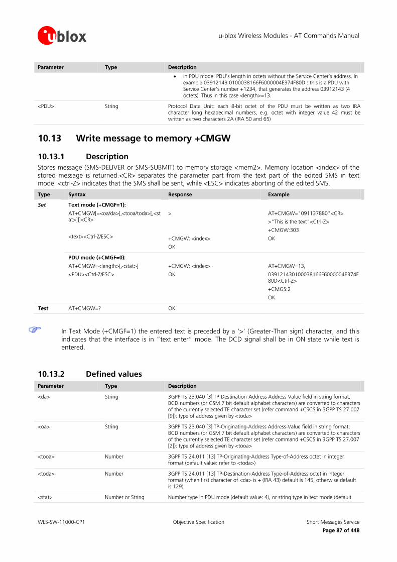
u-blox Wireless Modules - AT Commands Manual
WLS-SW-11000-CP1 Objective Specification Short Messages Service
Page 87 of 448
Parameter Type Description
in PDU mode: PDU’s length in octets without the Service Center’s address. In example:03912143 0100038166F6000004E374F80D : this is a PDU with Service Center’s number +1234, that generates the address 03912143 (4 octets). Thus in this case <length>=13.
<PDU> String Protocol Data Unit: each 8-bit octet of the PDU must be written as two IRA character long hexadecimal numbers, e.g. octet with integer value 42 must be written as two characters 2A (IRA 50 and 65)
10.13 Write message to memory +CMGW
10.13.1 Description
Stores message (SMS-DELIVER or SMS-SUBMIT) to memory storage <mem2>. Memory location <index> of the
stored message is returned.<CR> separates the parameter part from the text part of the edited SMS in text mode. <ctrl-Z> indicates that the SMS shall be sent, while <ESC> indicates aborting of the edited SMS.
Type Syntax Response Example
Set Text mode (+CMGF=1):
AT+CMGW[=<oa/da>[,<tooa/toda>[,<stat>]]]<CR>
<text><Ctrl-Z/ESC>
>
+CMGW: <index>
OK
AT+CMGW="091137880"<CR>
>"This is the text"<Ctrl-Z>
+CMGW:303
OK
PDU mode (+CMGF=0):
AT+CMGW=<length>[,<stat>]
<PDU><Ctrl-Z/ESC>
+CMGW: <index>
OK
AT+CMGW=13,
039121430100038166F6000004E374F80D<Ctrl-Z>
+CMGS:2
OK
Test AT+CMGW=? OK
In Text Mode (+CMGF=1) the entered text is preceded by a ‘>’ (Greater-Than sign) character, and this
indicates that the interface is in “text enter” mode. The DCD signal shall be in ON state while text is
entered.
10.13.2 Defined values
Parameter Type Description
<da> String 3GPP TS 23.040 [3] TP-Destination-Address Address-Value field in string format; BCD numbers (or GSM 7 bit default alphabet characters) are converted to characters of the currently selected TE character set (refer command +CSCS in 3GPP TS 27.007 [9]); type of address given by <toda>
<oa> String 3GPP TS 23.040 [3] TP-Originating-Address Address-Value field in string format; BCD numbers (or GSM 7 bit default alphabet characters) are converted to characters of the currently selected TE character set (refer command +CSCS in 3GPP TS 27.007 [2]); type of address given by <tooa>
<tooa> Number 3GPP TS 24.011 [13] TP-Originating-Address Type-of-Address octet in integer format (default value: refer to <toda>)
<toda> Number 3GPP TS 24.011 [13] TP-Destination-Address Type-of-Address octet in integer format (when first character of <da> is + (IRA 43) default is 145, otherwise default is 129)
<stat> Number or String Number type in PDU mode (default value: 4), or string type in text mode (default

u-blox Wireless Modules - AT Commands Manual
WLS-SW-11000-CP1 Objective Specification Short Messages Service
Page 88 of 448
Parameter Type Description
value: "ALL"); indicates the status of message in memory
0: in PDU mode or "REC UNREAD" in text mode: received unread SMS messages
1: in PDU mode or "REC READ" in text mode: received read SMS messages
2: in PDU mode or "STO UNSENT" in text mode: stored unsent SMS messages
3: in PDU mode or "STO SENT" in text mode: stored sent SMS messages
4: in PDU mode or "ALL" in text mode: all SMS messages
<text> String SMS String
<index> Number Storage position
<length> Number Two meanings:
in text mode: number of characters
in PDU mode: PDU’s length in octets without the Service Center’s address. In example:03912143 0100038166F6000004E374F80D : this is a PDU with Service Center’s number +1234, that generates the address 03912143 (4 octets). Thus in this case <length>=13.
<PDU> String Protocol Data Unit: each 8-bit octet of the PDU must be written as two IRA character long hexadecimal numbers, e.g. octet with integer value 42 must be written as two characters 2A (IRA 50 and 65)
10.14 Send message from storage +CMSS
10.14.1 Description
Sends message with location value <index> from the preferred message storage <mem2> to the network (SMS-SUBMIT or SMS-COMMAND). If a new recipient address <da> is given for SMS-SUBMIT, it will be used instead of
the one stored with the message. Reference value <mr> is returned to the DTE on successful message delivery.
Type Syntax Response Example
Set Text mode (+CMGF=1)::
AT+CMSS=<index>[,<da>[,<toda>]]
+CMSS: <mr>
OK
AT+CMSS=302
+CMSS: 3
OK
PDU mode (+CMGF=0):
AT+CMSS=<index>
+CMSS: <mr>
OK
AT+CMSS=302
+CMSS: 4
OK
Test AT+CMSS=? OK
10.14.2 Defined values
Parameter Type Description
<index> Number Storage position
<da> String Destination address
<toda> Number Type of address of <da> - octet
<mr> Number Message reference

u-blox Wireless Modules - AT Commands Manual
WLS-SW-11000-CP1 Objective Specification Short Messages Service
Page 89 of 448
10.15 Set text mode parameters +CSMP
10.15.1 Description
Selects values for additional parameters needed when SMS is sent to the network or placed in a storage when text format message mode is selected. For more details, refer to 3GPP TS 23.038 [7] and 3GPP TS 23.040 [8].
Type Syntax Response Example
Set AT+CSMP=<fo>,<vp>[,<pid>[,<dcs>]] OK AT+CSMP=17,167,0,0
OK
Read AT+CSMP? +CSMP: <fo>,<vp>,<pid>,<dcs>
OK
+CSMP: 17,167,0,0
OK
Test AT+CSMP=? OK
10.15.2 Defined values
Parameter Type Description
<fo> Number First octet of the SMS TPDU (see 3GPP TS 23.040 [8])
<vp> Number Format depending on the values of the bit3/bit4 of the <fo> (SMS-SUBMIT case):
bit 3 bit 4 Format
0 0 Validity period not present
0 1 Validity period present, relative format
1 0 Reserved
1 1 Validity period present, absolute format
Relative format: validity period, counted from when the SMS-SUBMIT is received by the SMSC, in range 0-255 (default value 167); for more details, refer to 3GPP TS 23.040 [8]
<vp> Validity period value
0 to 143 (TP-VP + 1) x 5 minutes (i.e. 5 minutes intervals up to 12 hours)
144 to 167 12 hours + ((TP-VP -143) x 30 minutes)
168 to 196 (TP-VP - 166) x 1 day
197 to 255 (TP-VP - 192) x 1 week
Absolute format: absolute time of the validity period termination in string format ("yy/MM/dd,hh:mm:ss+zz") (refer to 3GPP TS 23.040 [8]); the time zone is expressed in steps of 15 minutes
<pid> Number TP-Protocol-Identifier (default 0); refer to 3GPP TS 23.040 [8]
<dcs> Number Data Coding Scheme. Default value is 0
10.16 Delete SMS +CMGD
10.16.1 Description
Deletes message from preferred message storage <mem1>, if <flag> = 0 or not present, in location <index>. Otherwise the messages are deleted following the rules specified by <flag>.
When deleting a message from an empty location, the modem returns "OK".

u-blox Wireless Modules - AT Commands Manual
WLS-SW-11000-CP1 Objective Specification Short Messages Service
Page 90 of 448
If the <index> value is out of range (it depends on AT+CPMS command setting), then the error "+CMS ERROR: invalid memory index" is returned.
Type Syntax Response Example
Set AT+CMGD=<index>[,<flag>] OK AT+CMGD=3
OK
Test AT+CMGD=? +CMGD: (list of supported <index>s),(list of supported <flag>s)
OK
+CMGD: (1-350),(0-4)
OK
10.16.2 Defined values
Parameter Type Description
<index> Number Storage position
<flag> Number Deletion flag. If present, and different from 0, <index> is ignored:
0 (default value): Delete the message specified in <index>
1: Delete all read messages from preferred message storage, leaving unread messages and stored mobile originated messages (whether sent or not) untouched
2: Delete all read messages from preferred message storage and sent mobile originated messages, leaving unread messages and unsent mobile originated messages untouched
3: Delete all read messages from preferred message storage, sent and unsent mobile originated messages leaving unread messages untouched.
4: Delete all messages from preferred message storage including unread messages.
10.17 Service center address +CSCA
10.17.1 Description
Updates the SMSC address, through which mobile originated SMS’s are transmitted. In text mode the setting is
used by send and write commands. In PDU mode the setting is used by the same commands, but only when the
length of SMSC address coded into <pdu> parameter equals zero.
This command sets the service center value both in the RAM (this value is actually the SMSC address
used) and in the SIM card. Through the read command the value of current service center stored in the
RAM is displayed. At the power on, the MT reads the SMSC address in the SIM card and the same value is set in RAM.
Type Syntax Response Example
Set AT+CSCA=<sca>[,<tosca>] OK AT+CSCA="0170111000",129
OK
Read AT+CSCA? +CSCA: <sca>,<tosca>
OK
+CSCA: "",129
OK
Test AT+CSCA=? OK

u-blox Wireless Modules - AT Commands Manual
WLS-SW-11000-CP1 Objective Specification Short Messages Service
Page 91 of 448
10.17.2 Defined values
Parameter Type Description
<sca> String Service center address
<tosca> String Type of address of <sca> (for more details refer to 3GPP TS 24.008 [12]); default 145 when string includes ‘+’, otherwise default 129
10.18 Select cell broadcast message types +CSCB
10.18.1 Description
This set command selects which types of CBM’s are to be received by the MT.
Type Syntax Response Example
Set AT+CSCB=[<mode>[,<mids>[,<dcss>]]] OK AT+CSCB=0,"1,5,10-11,40",""
OK
Read AT+CSCB? +CSCB: <mode>,<mids>,<dcss>
OK
+CSCB: 0,"",""
OK
Test AT+CSCB=? +CSCB: (list of supported <mode>s)
OK
+CSCB: (0-1)
OK
10.18.2 Defined values
Parameter Type Description
<mode> Number 0: message types specified in <mids> and <dcss> are accepted
1: message types specified in <mids> and <dcss> are not accepted
<mids> String Contains all possible combinations of CBM message identifiers (<mid>). Refer to 3GPP TS 23.041 [9], chapter 9.4
<dcss> String Contains all possible combinations of CBM data coding schemes (<dcs>). Refer to 3GPP TS 23.038 [7], chapter 5
If <mode>=0 and <mids> is an empty string, receiving of CB SMS is stopped.
10.19 Read concatenated message +UCMGR
10.19.1 Description
Returns the message with location value <index> from message storage <mem1> to the DTE and shows
additional information when the message is a segment of a concatenated one.
Not supported by LEON-G100-05S / LEON-G200-05S and previous versions.
For SMS-DELIVER the parameters <tooa>, <fo>, <pid>, <dcs>, <sca>, <tosca>, <length> shall be
displayed only if +CSDH=1 is set.
For SMS-SUBMIT the parameters <toda>, <fo>, <pid>, <dcs>, <vp>, <sca>, <tosca>, <length> shall be
displayed only if +CSDH=1 is set.
For SMS-COMMAND <pid>, <mn>, <da>, <toda>, <length> <cdata> shall be displayed only if +CSDH=1 is set.

u-blox Wireless Modules - AT Commands Manual
WLS-SW-11000-CP1 Objective Specification Short Messages Service
Page 92 of 448
The syntax AT+UCMGR=0 allows to display an SMS class 0 if it is signalized to MT, because no MMI is available in the MT (see also the note from command +CNMI, chapter 10.8).
If status of the received message is “received unread”, status in the storage changes to “received read”.
The command is supported only for text mode (+CMGF=1).
If the <index> value is out of range (it depends on the preferred message storage, +CPMS command,
settings) or it refers to an empty position, then the error "+CMS ERROR: invalid memory index" is returned.
Type Syntax Response Example
Set AT+UCMGR=<index> (SMS-DELIVER)
+UCMGR: <stat>,<oa>,[<alpha>],<scts>[,<tooa>, <fo>,<pid>,<dcs>,<sca>,<tosca>,<length>][,<seq>,<max>,<iei>,<ref>]
<data>
OK
(SMS-SUBMIT)
+UCMGR: <stat>,<da>,[<alpha>][<toda>,<fo>,<pid>,<dcs>,[<vp>],<sca>,<tosca>,<length>][,<seq>,<max>,<iei>,<ref>]
<data>
OK
(SMS-STATUS-report)
+UCMGR:<stat>,<fo>,<mr>,[<ra>],[<tora>]<scts><dt>,<st>
OK
(SMS-COMMAND)
+UCMGR: <stat>,<fo>,<ct>[,<pid>,[<mn>],[<da>],[<toda>],<length>
[<cdata>]]
OK
(CBM storage)
+UCMGR: <stat>,<sn>,<mid>,<dcs>,<page>,<pages>
<data>
OK
AT+UCMGR=303
+UCMGR:"REC READ","+393488535999",,"07/04/05,18:02:28+08",145,4,0,0,"+393492000466",145,152,1,2,8,15
aaaaaaaaaaaaaaaaaaaabbbbbbbbbbbbbbbbbbbbccccccccccccccccccccddddddddddddddddddddeeeeeeeeeeeeeeeeeeeeffffffffffffffffffffgggggggggggggggggggghhhhhhhhhhhh
OK
Test AT+UCMGR=? OK
10.19.2 Defined values
Parameter Type Description
<index> Number Storage position
<stat> String Indicates the status of message in memory:
"REC UNREAD": received unread SMS
"REC READ": received read SMS
"STO UNSENT": stored unsent SMS
"STO SENT": stored sent SMS
"ALL": all SMS messages

u-blox Wireless Modules - AT Commands Manual
WLS-SW-11000-CP1 Objective Specification Short Messages Service
Page 93 of 448
Parameter Type Description
<oa> String Originator address
<alpha> String Alphanumeric representation of <da> or <oa> corresponding to the entry found in the phonebook 3GPP TS 24.008 [12]. The parameter is not managed.
<scts> String Service center time stamp in time-string format, refer to <dt>
<tooa> Number Type of address of <oa> - octet
<fo> Number First octet of the SMS TPDU (see 3GPP TS 23.040 [8])
<pid> Number TP-Protocol-Identifier (default 0); refer to 3GPP TS 23.040 [8]
<dcs> Number Data Coding Scheme
<sca> String Service center address field
<tosca> Number Type of address of <sca> - octet in Number format (for more details, refer to 3GPP TS 24.008 [12]); default 145 when string includes ‘+’, otherwise default 129
<length> Number Number of characters
<seq> Number Sequence number of the current short message (1-255)
<max> Number Maximum number of short messages in the concatenated short message (1-255)
<iei> Number Information Element Identifier, the possible values are the following:
0: Concatenated short messages, 8-bit reference number
8: Concatenated short messages, 16-bit reference number
<ref> Number Concatenated short message reference number:
0-255: Concatenated short messages, 8-bit reference number case
0-65535: Concatenated short messages, 16-bit reference number case
<data> String In the case of SMS: 3GPP TS 23.040 [8] TP-User-Data in text mode responses; format:
if <dcs> indicates that 3GPP TS 23.038 [7] GSM 7 bit default alphabet is used and <fo> indicates that 3GPP TS 23.040 [8] TP-User-Data-Header-Indication is not set:
o if TE character set other than “HEX” (refer command Select TE Character Set +CSCS chapter 4.5): ME/TA converts GSM alphabet into current TE character set according to rules of 3GPP TS 27.005 [16] Annex A
o if TE character set is “HEX”: ME/TA converts each 7-bit character of GSM 7 bit default alphabet into two IRA character long hexadecimal
number (e.g. character (GSM 7 bit default alphabet 23) is presented as 17 (IRA 49 and 55))
if <dcs> indicates that 8-bit or UCS2 data coding scheme is used, or <fo> indicates that 3GPP TS 23.040 [8] TP-User-Data-Header-Indication is set: ME/TA converts each 8-bit octet into two IRA character long hexadecimal number (e.g. octet with integer value 42 is presented to TE as two characters 2A (IRA 50 and 65))
In the case of CBS: 3GPP TS 23.041 [9] CBM Content of Message in text mode responses; format:
if <dcs> indicates that 3GPP TS 23.038 [7] GSM 7 bit default alphabet is used:
o if TE character set other than “HEX” (refer command +CSCS chapter 26.15): ME/TA converts GSM alphabet into current TE character set according to rules of 3GPP TS 27.005 [16] Annex A
o if TE character set is “HEX”: ME/TA converts each 7-bit character of the GSM 7 bit default alphabet into two IRA character long hexadecimal number
if <dcs> indicates that 8-bit or UCS2 data coding scheme is used: ME/TA converts each 8-bit octet into two IRA character long hexadecimal number
<da> String Destination address

u-blox Wireless Modules - AT Commands Manual
WLS-SW-11000-CP1 Objective Specification Short Messages Service
Page 94 of 448
Parameter Type Description
<toda> Number Type of address of <da> - octet
<vp> Number Format depending of the <fo> setting:
Relative format: validity period starting from when the SMS is received by the SMSC, in range 0-255 (default value 167); for more details, refer to 3GPP TS 23.040 [8]
<vp> Validity period value
0 to 143 (TP-VP + 1) x 5 minutes (i.e. 5 minutes intervals up to 12 hours)
144 to 167 12 hours + ((TP-VP -143) x 30 minutes)
168 to 196 (TP-VP - 166) x 1 day
197 to 255 (TP-VP - 192) x 1 week
Absolute format: absolute time of the validity period termination in string format ("yy/MM/dd,hh:mm:ss+zz") (refer to 3GPP TS 23.040 [8]); the time zone is expressed in steps of 15 minutes
<mr> Number Message reference
<ra> String Recipient address field
<tora> Number Type of address of <ra> - octet
<scts> String Service center time stamp in time-string format, refer to <dt>
<dt> String Discharge time in format "yy/MM/dd,hh:mm:ss+zz"; the time zone is expressed in steps of 15 minutes
<st> Number Status of an SMS STATUS-REPORT
<ct> Number TP-Command-Type (default 0)
<mn> Number 3GPP TS 23.040 [8] TP-Message-Number in integer format
<mid> Number CBM message identifier
<cdata> String TP-Command-Data in text mode responses
<sn> Number CBM serial number
<page> Number 3GPP TS 23.041 [9] CBM Page Parameter bits 4-7 in integer format
<pages> Number 3GPP TS 23.041 [9] CBM Page Parameter bits 0-3 in integer format
10.20 List concatenated message +UCMGL
10.20.1 Description
Returns SMS messages with status value <stat> from message storage <mem1> to the DTE and shows
additional information when the message is a segment of a concatenated one.
Not supported by LEON-G100-05S / LEON-G200-05S and previous versions.
For SMS-DELIVER the parameters <tooa>, <length> shall be displayed only if +CSDH=1 is set.
For SMS-SUBMIT the parameters <toda>, <length> shall be displayed only if +CSDH=1 is set.
If status of the received message is “received unread”, status in the storage changes to “received read”.
The command is supported only for text mode (+CMGF=1).

u-blox Wireless Modules - AT Commands Manual
WLS-SW-11000-CP1 Objective Specification Short Messages Service
Page 95 of 448
Type Syntax Response Example
Set AT+UCMGL[=<stat>] SMS-DELIVERs:
+UCMGL: <index>,<stat>,<oa>,[<alpha>],[<scts>][,<tooa>,<length>][,<seq>,<max>,<iei>,<ref>]
<data>
[+UCMGL: <index>,<stat>,<oa>,[<alpha>],[<scts>][,<tooa>,<length>][,<seq>,<max>,<iei>,<ref>]<data>[…]]
OK
AT+UCMGL
+UCMGL: 303,"REC READ","+393401234999",,"08/08/06,10:01:38+08",145,68,2,2,8,15
hhhhhhhhiiiiiiiiiiiiiiiiiiiillllllllllllllllllllmmmmmmmmmmmmmmmmmmmm
OK
SMS-SUBMITs:
+UCMGL: <index>,<stat>,<da>,[<alpha>],[<toda>, <length>][,<seq>,<max>,<iei>,<ref>]
<data>
[+UCMGL: <index>,<stat>,<da>,[<alpha>],[<toda>,<length>][,<seq>,<max>,<iei>,<ref>]<data>[…]]
OK
SMS-STATUS-REPORTs:
+UCMGL: <index>,<stat>,<fo>,<mr>,[<ra>],[<tora>],<scts>,<dt>,<st>
[+UCMGL: <index>,<stat>,<fo>,<mr>,[<ra>],[<tora>],<scts>,<dt>,<st> […]]
OK
SMS-COMMANDs:
+UCMGL: <index>,<stat>,<fo>,<ct>
[+UCMGL: <index>,<stat>,<fo>,<ct>[…]]
OK
CBM storage:
+UCMGL: <index>,<stat>,<sn>,<mid>,<page>,<pages><data>
[+UCMGL: <index>,<stat>,<sn>,<mid>,<page>,<pages>,<data>[…]]
OK
Test AT+UCMGL=? +UCMGL: (list of supported <stat>s)
OK
+UCMGL: ("REC UNREAD","REC READ","STO UNSENT","STO SENT","ALL ")
OK
10.20.2 Defined values
Parameter Type Description
<stat> String Indicates the status of message in memory:
"REC UNREAD": received unread SMS messages
"REC READ": received read SMS messages
"STO UNSENT": stored unsent SMS messages
"STO SENT": stored sent SMS messages
"ALL": all SMS messages (default value)
<index> Number Storage position
<oa> String Originator address

u-blox Wireless Modules - AT Commands Manual
WLS-SW-11000-CP1 Objective Specification Short Messages Service
Page 96 of 448
Parameter Type Description
<alpha> String Alphanumeric representation of <da> or <oa> corresponding to the entry found in the phonebook 3GPP TS 24.008 [12]. The parameter is not managed.
<scts> String Service center time stamp in time-string format; refer to <dt>
<tooa> Number Type of address of <oa> - octet
<length> Number Number of characters
<seq> Number Sequence number of the current short message (1-255)
<max> Number Maximum number of short messages in the concatenated short message (1-255)
<iei> Number Information Element Identifier, the possible values are the following:
0: Concatenated short messages, 8-bit reference number
8: Concatenated short messages, 16-bit reference number
<ref> Number Concatenated short message reference number:
0-255: Concatenated short messages, 8-bit reference number case
0-65535: Concatenated short messages, 16-bit reference number case
<data> String In the case of SMS: 3GPP TS 23.040 [8] TP-User-Data in text mode responses; format:
if <dcs> indicates that 3GPP TS 23.038 [7] GSM 7 bit default alphabet is used and <fo> indicates that 3GPP TS 23.040 [8] TP-User-Data-Header-Indication is not set:
o if TE character set other than “HEX” (refer command Select TE Character Set +CSCS chapter 26.15): ME/TA converts GSM alphabet into current TE character set according to rules of 3GPP TS 27.005 Annex A [16]
o if TE character set is “HEX”: ME/TA converts each 7-bit character of GSM 7 bit default alphabet into two IRA character long hexadecimal
number (e.g. character (GSM 7 bit default alphabet 23) is presented as 17 (IRA 49 and 55))
if <dcs> indicates that 8-bit or UCS2 data coding scheme is used, or <fo> indicates that 3GPP TS 23.040 [8] TP-User-Data-Header-Indication is set: ME/TA converts each 8-bit octet into two IRA character long hexadecimal number (e.g. octet with integer value 42 is presented to TE as two characters 2A (IRA 50 and 65))
In the case of CBS: 3GPP TS 23.041 [9] CBM Content of Message in text mode responses; format:
if <dcs> indicates that 3GPP TS 23.038 [7] GSM 7 bit default alphabet is used:
o if TE character set other than “HEX” (refer command +CSCS chapter 26.15): ME/TA converts GSM alphabet into current TE character set according to rules of 3GPP TS 27.005 [16]Annex A
if TE character set is “HEX”: ME/TA converts each 7-bit character of the GSM 7 bit default alphabet into two IRA character long hexadecimal number
if <dcs> indicates that 8-bit or UCS2 data coding scheme is used: ME/TA converts each 8-bit octet into two IRA character long hexadecimal number
<da> String Destination address
<toda> Number Type of address of <da> - octet
<fo> Number First octet of the SMS TPDU (see 3GPP TS 23.040 [8])
<mr> Number Message reference
<ra> String Recipient address field
<tora> Number Type of address of <ra> - octet
<dt> String Discharge time in format "yy/MM/dd,hh:mm:ss+zz"; the time zone is expressed in steps of 15 minutes
<st> Number Status of an SMS STATUS-REPORT

u-blox Wireless Modules - AT Commands Manual
WLS-SW-11000-CP1 Objective Specification Short Messages Service
Page 97 of 448
Parameter Type Description
<ct> Number TP-Command-Type (default 0)
<sn> Number CBM serial number
<mid> Number CBM message identifier
<page> Number 3GPP TS 23.041 [9] CBM Page Parameter bits 4-7 in integer format
<pages> Number 3GPP TS 23.041 [9] CBM Page Parameter bits 0-3 in integer format
<dcs> Number Data Coding Scheme
10.21 Send concatenated message +UCMGS
10.21.1 Description
Sends one segment of a concatenated message from a DTE to the network (SMS-SUBMIT). Message reference value <mr> is returned to the DTE on successful message delivery. <CR> separates the parameter part from the
text part of the edited SMS in text mode. <ctrl-Z> indicates that the SMS shall be sent, while <ESC> indicates
aborting of the edited SMS.
Not supported by LEON-G100-05S / LEON-G200-05S and previous versions.
The command is supported only for text mode (+CMGF=1).
Type Syntax Response Example
Set AT+UCMGS=<da>,[<toda>],<seq>,<max>,<iei>,<ref><CR>
<text><Ctrl-Z/ESC>
+UCMGS: <mr>
OK
AT+UCMGS="0171112233",,1,2,8,15<CR> aaaaaaaaaaaaaaaaaaaabbbbbbbbbbbbbbbbbbbbccccccccccccccccccccddddddddddddddddddddeeeeeeeeeeeeeeeeeeeeffffffffffffffffffffgggggggggggggggggggghhhhhhhhhhhh
<Ctrl-Z>
+UCMGS:2
OK
Test AT+UCMGS=? OK
10.21.2 Defined values
Parameter Type Description
<da> String Destination address
<toda> Number Type of address of <da> - octet
<seq> Number Sequence number of the current short message (1-255)
<max> Number Maximum number of short messages in the concatenated short message (1-255)
<iei> Number Information Element Identifier, the possible values are the following:
0: Concatenated short messages, 8-bit reference number
8: Concatenated short messages, 16-bit reference number
<ref> Number Concatenated short message reference number:
0-255: Concatenated short messages, 8-bit reference number case
0-65535: Concatenated short messages, 16-bit reference number case

u-blox Wireless Modules - AT Commands Manual
WLS-SW-11000-CP1 Objective Specification Short Messages Service
Page 98 of 448
Parameter Type Description
<text> String SMS String
<mr> Number Message reference
10.22 Write concatenated message to memory +UCMGW
10.22.1 Description
Stores one segment of a concatenated message (SMS-DELIVER or SMS-SUBMIT) to memory storage <mem2>.
Memory location <index> of the stored message is returned. <CR> separates the parameter part from the text part of the edited SMS in text mode. <ctrl-Z> indicates that the SMS shall be sent, while <ESC> indicates
aborting of the edited SMS.
Not supported by LEON-G100-05S / LEON-G200-05S and previous versions.
The command is supported only for text mode (+CMGF=1)
Type Syntax Response Example
Set AT+UCMGW=[<oa/da>],[<tooa/toda>],[<stat>],<seq>,<max>,<iei>,<ref><CR>
<text><Ctrl-Z/ESC>
+UCMGW: <index>
OK
AT+UCMGW="091137880",,,2,2,8,15<CR>
hhhhhhhhiiiiiiiiiiiiiiiiiiiillllllllllllllllllllmmmmmmmmmmmmmmmmmmmm
<Ctrl-Z>
+UCMGW:303
OK
Test AT+UCMGW=? OK
10.22.2 Defined values
Parameter Type Description
<da> String 3GPP TS 23.040 [8] TP-Destination-Address Address-Value field in string format; BCD numbers (or GSM 7 bit default alphabet characters) are converted to characters of the currently selected TE character set (refer command +CSCS in 3GPP TS 27.007 [2]); type of address given by <toda>
<oa> String 3GPP TS 23.040 [8] TP-Originating-Address Address-Value field in string format; BCD numbers (or GSM 7 bit default alphabet characters) are converted to characters of the currently selected TE character set (refer command +CSCS chapter 4.5); type of address given by <tooa>
<tooa> Number 3GPP TS 24.011 [13] TP-Originating-Address Type-of-Address octet in integer format (default refer <toda>)
<toda> Number 3GPP TS 24.011 [13] TP-Destination-Address Type-of-Address octet in integer format (when first character of <da> is + (IRA 43) default is 145, otherwise default is 129)
<stat> String Indicates the status of message in memory:
"REC UNREAD": received unread SMS messages
"REC READ": received read SMS messages
"STO UNSENT": stored unsent SMS messages
"STO SENT": stored sent SMS messages (default value)
<seq> Number Sequence number of the current short message (1-255)

u-blox Wireless Modules - AT Commands Manual
WLS-SW-11000-CP1 Objective Specification Short Messages Service
Page 99 of 448
Parameter Type Description
<max> Number Maximum number of short messages in the concatenated short message (1-255)
<iei> Number Information Element Identifier, the possible values are the following:
0: Concatenated short messages, 8-bit reference number
8: Concatenated short messages, 16-bit reference number
<ref> Number Concatenated short message reference number:
0-255: Concatenated short messages, 8-bit reference number case
0-65535: Concatenated short messages, 16-bit reference number case
<text> String SMS String
<index> Number Storage position
10.23 More Messages to Send +CMMS
10.23.1 Description
Controls the continuity of SMS relay protocol link. When enabled, multiple SMS messages can be sent much faster as link is kept open.
Type Syntax Response Example
Set AT+CMMS=[<mode>] OK AT+CMMS=2
OK
Read AT+CMMS? +CMMS: <mode>
OK
+CMMS: 2
OK
Test AT+CMMS=? +CMMS: (list of supported <mode>s)
OK
+CMMS: (0-2)
OK
10.23.2 Defined values
Parameter Type Description
<mode> Number 0: disable (default)
1: keep enabled until the time between the response of the latest message send command (such as +CMGS) and the next send command exceeds 5 seconds, then close the link and switch <mode> automatically back to 0
2: keep permanently enabled. The link is closed after each send sequence, but <mode> is not switched back to 0
10.24 Peek message +UCMGP
10.24.1 Description
Returns the message with location value <index> from message storage <mem1> to the DTE, the same as
+CMGR does.
The SMS message is only ‘peeked’, i.e. its status is not forced to “received read SMS mode” after reading.
The syntax, defined values and remarks are the same as described for +CMGR.
The +UCMGP command is not available on LISA-U200-00S version.

u-blox Wireless Modules - AT Commands Manual
WLS-SW-11000-CP1 Objective Specification Short Messages Service
Page 100 of 448
Type Syntax Response Example
Set Text mode (+CMGF=1):
AT+UCMGP=<index>
(SMS-DELIVER)
+UCMGP: <stat>,<oa>,[<alpha>],<scts>[,<tooa>, <fo>,<pid>,<dcs>,<sca>,<tosca>,<length>]
<data>
OK
(SMS-SUBMIT)
+UCMGP: <stat>,<da>,[<alpha>][<toda>,<fo>,<pid>,<dcs>,[<vp>],<sca>,<tosca>,<length>]
<data>
OK
(SMS-STATUS-report)
+UCMGP: <stat>,<fo>,<mr>,[<ra>],[<tora
>]<scts><dt>,<st>
OK
(SMS-COMMAND)
+UCMGP: <stat>,<fo>,<ct>[,<pid>,[<mn>],[<da>],[<toda>],<length>
[<cdata>]]
OK
(CBM storage)
+UCMGP: <stat>,<sn>,<mid>,<dcs>,<page>,<pages>
<data>
OK
AT+UCMGP=303
+UCMGP: "REC UNREAD","+393488535999",,"07/04/05,18:02:28+08",145,4,0,0,"+393492000466",145,93
You have a missed called. Free information provided by your operator.
OK
Text mode (+CMGF=0):
AT+UCMGP=<index>
+UCMGP: <stat>,[<alpha>],<length>
<pdu>
OK
AT+UCMGP=1
+CMGR: 0,,40
0791934329002000040C9193230982
661400008070328045218018D4F29CF
E06B5CBF379F87C4EBF41E434082E7F
DBC3
OK
10.24.2 Defined values
Parameter Type Description
<index> Number Storage position

u-blox Wireless Modules - AT Commands Manual
WLS-SW-11000-CP1 Objective Specification Supplementary services
Page 101 of 448
11 Supplementary services
11.1 Call forwarding +CCFC
11.1.1 Description
Controls the call forwarding supplementary service according. Registration, erasure, activation, deactivation and
status query are supported. This command can be aborted.
Type Syntax Response Example
Set AT+CCFC=<reason>,<mode>[,<number>[,<type>[,<class>[,<subaddr>[,<satype>[,<time>]]]]]]
OK
or
when <mode>=2
+CCFC: <status>,<class1>[,<number>,<type> [,<subaddr>, <satype>[,<time>]]]
[+CCFC: <status>,<class2> [,<number>, <type>[,<subaddr>,<satype>[,<time>]]]
Registration:
AT+CCFC=0,3,"01711234"
OK
Query status:
AT+CCFC=2,2
+CCFC: 1,1,"+3945112",145,"",,60
OK
Test AT+CCFC=? +CCFC: (list of supported <reason>s)
OK
+CCFC: (0-5)
OK
11.1.2 Defined values
Parameter Type Description
<reason> Number 0: unconditional
1: mobile busy
2: no reply
3: not reachable
4: all call forwarding
5: all conditional call forwarding
<mode> Number 0: disable
1: enable
2: query status
3: registration
4: erasure
<number> String Phone number of forwarding address in <type> format
<type> Number Type of address; default 145 when dialling string includes ‘+’, otherwise 129
<subaddr> String Subaddress; parameter currently ignored after syntax check
<satype> Number Type of subaddress; default 128 (TON/NPI unknown); parameter currently ignored after syntax check

u-blox Wireless Modules - AT Commands Manual
WLS-SW-11000-CP1 Objective Specification Supplementary services
Page 102 of 448
Parameter Type Description
<classx> Number Sum of Numbers each representing a class of information (default 7 - voice (1), data (2) and FAX (4) - or interpreted by network if not explicitly entered)
1: voice
2: data
4: FAX
8: SMS
16: data circuit sync
32: data circuit async
64: dedicated packet access
128: dedicated PAD access
<time> Number Time in seconds to wait before call is forwarded (default 60), but only when <reason>=2 (no reply) is enabled; the range goes from 5 to 30 s
<status> Number 0: not active
1: active
11.2 Call waiting +CCWA
11.2.1 Description
Controls the Call Waiting supplementary service according to 3GPP TS 22.083 [33]. Activation, deactivation and
status query are supported. When querying the status of a network service (<mode>=2) the response line for 'not active' case (<status>=0) should be returned only if service is not active for any <class>. Status query is
abortable if a character is sent to DCE during the command execution. If enabled by <n> a URC is presented on
TE when a call is signaled.
Type Syntax Response Example
Set Set Command
AT+CCWA=[<n>[,<mode>[,<class>]]]
Query Command
AT+CCWA=[<n>[,<mode>]]
Set Command
OK
Query Command
+CCWA: <status>,<class1>
[+CCWA: <status>,<class2>
[…]]
OK
Set command
AT+CCWA=1,1,32
OK
Query Command
AT+CCWA=1,2
+CCWA: 1,1
+CCWA: 1,4
+CCWA: 1,16
+CCWA: 1,32
OK
Read AT+CCWA? +CCWA: <n>
OK
+CCWA: 0
OK
Test AT+CCWA=? +CCWA: (list of supported <n>s)
OK
+CCWA: (0-1)
OK
URC +CCWA: <number>,<type>,<class>,[<alpha>][,<CLI validity>[,<subaddr>,<satype>[,<priority>]]]

u-blox Wireless Modules - AT Commands Manual
WLS-SW-11000-CP1 Objective Specification Supplementary services
Page 103 of 448
11.2.2 Defined values
Parameter Type Description
<n> Number Enable/disable the presentation of a URC +CCWA
0: disable
1: enable
<mode> Number If <mode> not given, network is not interrogated
0: disable
1: enable
2: query status
<classx> Number Sum of numbers each representing an information class :
default is 3 if <classx> is not set and <mode> is 0 or 1
default is 255 if <classx> is not set and <mode> is 2 e.g. it reports all active classes if any. If no class is active only class 1 and 2 are reported as inactive:
+CCWA: 0,1
+CCWA: 0,2
1: voice
2: data; it comprises all those <classx> values between 16 and 128, that are supported both by the network and the MS. This means, a setting made for <classx> to 2 applies to all remaining data classes (if supported). In addition, it is possible to assign a different setting to a specific class. For example, call waiting can be deactivated only for a specific data class. To understand which classes were actually activated AT+CCWA=1,2 command should be executed
4: FAX currently not supported
8: SMS
16: data circuit sync
32: data circuit async
64: dedicated packet access
128: dedicated PAD access
255: cover all classes
All values are network dependant. If a sum class is provided they will be activated in cardinal order (minimum to maximum). If a class is not supported then the procedure ends and any remaining class is not processed. To check which classes were actually activated AT+CCWA=1,2 command should be done.
<status> Number 0: not active
1: active
<number> String Phone number of calling address in format specified by <type>
<type> Number Type of address
<alpha> String Optional string type alphanumeric representation of <number> corresponding to the entry found in phonebook; this parameter is not managed
<CLI validity> Number 0: CLI valid
1: CLI has been withheld by the originator
2: CLI is not available
<cause of no cli> Number 0: unavailable
1: reject by user
2: interaction with other service
3: coin line/payphone
<subaddr> String Subaddress of format specified by <satype>
<satype> Number Subaddress octet (refer to 3GPP TS 24.008 subclause 10.5.4.8 [30])

u-blox Wireless Modules - AT Commands Manual
WLS-SW-11000-CP1 Objective Specification Supplementary services
Page 104 of 448
Parameter Type Description
<priority> Number Optional digit type parameter indicating that the eMLPP priority level of the incoming call. The priority level values are as defined in eMLPP specification 3GPP TS 22.067 [59].
If call waiting is not handled in uniform mode among all networks even if the GSM 02.04 [3] describes all needed specification: "The applicability of call waiting refers to the telecommunication service of the
active call and not of the waiting call. The incoming, waiting, call may be of any kind." Nevertheless, the
actual implementation of the service on the networks is different.
11.3 Calling line identification restriction +CLIR
11.3.1 Description
Controls calling line identification restriction supplementary service (3GPP 22.081 [34]). This command can be aborted.
Type Syntax Response Example
Set AT+CLIR=[<n>] OK AT+CLIR=2
OK
Read AT+CLIR? +CLIR: <n>,<m>
OK
+CLIR: 0,2
OK
Test AT+CLIR=? +CLIR: (list of supported <n>s)
OK
+CLIR: (0-2)
OK
11.3.2 Defined values
Parameter Type Description
<n> Number Sets the adjustment for outgoing calls
0: presentation indicator is used according to the subscription of the CLIR service
1: CLIR invocation
2: CLIR suppression
<m> Number Shows the subscriber CLIR status in the network
0: CLIR not provisioned
1: CLIR provisioned in permanent mode
2: unknown
3: CLIR temporary mode presentation restricted
4: CLIR temporary mode presentation allowed
11.4 Calling line identification presentation +CLIP
11.4.1 Description
Controls the calling line identification presentation supplementary service. When CLI (Calling Line Identification) is enabled, +CLIP response is returned after every RING result code. The URC is displayed after RING if the CLI
presentation at the TE is enabled.
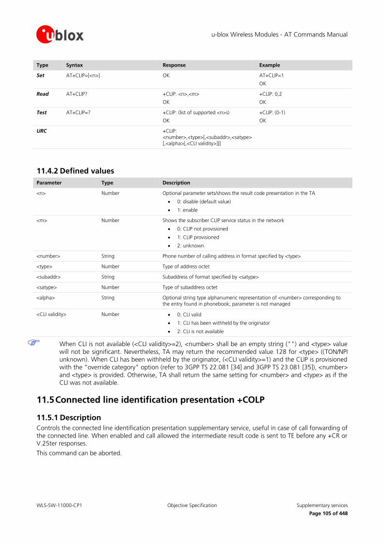
u-blox Wireless Modules - AT Commands Manual
WLS-SW-11000-CP1 Objective Specification Supplementary services
Page 105 of 448
Type Syntax Response Example
Set AT+CLIP=[<n>] OK AT+CLIP=1
OK
Read AT+CLIP? +CLIP: <n>,<m>
OK
+CLIP: 0,2
OK
Test AT+CLIP=? +CLIP: (list of supported <n>s)
OK
+CLIP: (0-1)
OK
URC +CLIP: <number>,<type>[,<subaddr>,<satype>[,<alpha>[,<CLI validity>]]]
11.4.2 Defined values
Parameter Type Description
<n> Number Optional parameter sets/shows the result code presentation in the TA
0: disable (default value)
1: enable
<m> Number Shows the subscriber CLIP service status in the network
0: CLIP not provisioned
1: CLIP provisioned
2: unknown
<number> String Phone number of calling address in format specified by <type>
<type> Number Type of address octet
<subaddr> String Subaddress of format specified by <satype>
<satype> Number Type of subaddress octet
<alpha> String Optional string type alphanumeric representation of <number> corresponding to the entry found in phonebook; parameter is not managed
<CLI validity> Number 0: CLI valid
1: CLI has been withheld by the originator
2: CLI is not available
When CLI is not available (<CLI validity>=2), <number> shall be an empty string ("") and <type> value
will not be significant. Nevertheless, TA may return the recommended value 128 for <type> ((TON/NPI unknown). When CLI has been withheld by the originator, (<CLI validity>=1) and the CLIP is provisioned
with the "override category" option (refer to 3GPP TS 22.081 [34] and 3GPP TS 23.081 [35]), <number>
and <type> is provided. Otherwise, TA shall return the same setting for <number> and <type> as if the CLI was not available.
11.5 Connected line identification presentation +COLP
11.5.1 Description
Controls the connected line identification presentation supplementary service, useful in case of call forwarding of
the connected line. When enabled and call allowed the intermediate result code is sent to TE before any +CR or V.25ter responses.
This command can be aborted.

u-blox Wireless Modules - AT Commands Manual
WLS-SW-11000-CP1 Objective Specification Supplementary services
Page 106 of 448
Type Syntax Response Example
Set AT+COLP=[<n>] OK AT+COLP=1
OK
Read AT+COLP? +COLP: <n>,<m>
OK
+COLP: 0,2
OK
Test AT+COLP=? +COLP: (list of supported <n>s)
OK
+COLP: (0-1)
OK
IRC +COLP: <number>,<type>[,<subaddr>,<satype>[,<alpha>]]
11.5.2 Defined values
Parameter Type Description
<n> Number Optional parameter sets/shows the result code presentation status in the TA
0: disable (default value)
1: enable
<m> Number Shows the subscriber COLP status in the network
0: COLP not provisioned
1: CLIR provisioned in permanent mode
2: unknown
<number>, <type>, <subaddr>, <satype>, <alpha>
See +CLIP (chapter 11.4)
11.6 Connected line identification restriction +COLR
11.6.1 Description
Enables connected party to prevent presentation of its line identity to the calling party. According to
GSM02.81 [34] the activation and deactivation of COLR is only a result of provision / withdrawal. The command
+COLR allows only the interrogation of the current state of COLR service in the network. The set syntax is not allowed (+CME ERROR: operation not supported).
Type Syntax Response Example
Read AT+COLR? +COLR: <status>
OK
+COLR: 2
OK
Test AT+COLR=? OK
11.6.2 Defined values
Parameter Type Description
<status> Number Shows the subscriber COLR service status in the network
0: COLR not provisioned
1: COLR provisioned
2: unknown

u-blox Wireless Modules - AT Commands Manual
WLS-SW-11000-CP1 Objective Specification Supplementary services
Page 107 of 448
11.7 Advise of charge +CAOC
11.7.1 Description
Allows the subscriber to get the information about the call costs in home units using the Advise of Charge supplementary service (3GPP TS 22.024 [37] and 3GPP TS 22.086 [36]). If enabled the URC is periodically sent to
TE.
Type Syntax Response Example
Set AT+CAOC[=<mode>] [+CAOC: <ccm>]
OK
AT+CAOC=0
OK
Read AT+CAOC? +CAOC: <mode>
OK
+CAOC: 1
OK
Test AT+CAOC=? +CAOC: (list of supported <mode>s)
OK
+CAOC: (0-2)
OK
URC +CAOC: <ccm>
11.7.2 Defined values
Parameter Type Description
<mode> Number 0: query the CCM value
1: deactivate the unsolicited reporting of CCM value
2: activate the unsolicited reporting of CCM value
<ccm> Number Current call meter indicated as a string in hexadecimal format
11.8 Accumulated call meter +CACM
11.8.1 Description
Resets the Advice of charge related accumulated call meter value in SIM file EF-ACM. ACM contains the total
number of home units for both the current and preceding calls. SIM PIN2 is required to reset the value.
Type Syntax Response Example
Set AT+CACM=[<passwd>] OK AT+CACM="0933"
OK
Read AT+CACM? +CACM: <acm>
OK
+CACM: "000000"
OK
Test AT+CACM=? OK
11.8.2 Defined values
Parameter Type Description
<passwd> String SIM PIN2 as string type
<acm> String Accumulated call meter value similarly coded as <ccm> under +CAOC

u-blox Wireless Modules - AT Commands Manual
WLS-SW-11000-CP1 Objective Specification Supplementary services
Page 108 of 448
11.9 Accumulated call meter maximum +CAMM
11.9.1 Description
Sets the Advise of Charge related accumulated call meter maximum value in the SIM file EF-ACMmax. ACMmax contains the maximum number of home units allowed to be consumed by the subscriber. When ACM reaches
ACMmax, calls are prohibited. SIM PIN2 is required to set the value.
Type Syntax Response Example
Set AT+CAMM=[<acmmax>[,<passwd>]] OK AT+CAMM="000300","0933"
OK
Read AT+CAMM? +CAMM: <acmmax>
OK
+CAMM: "000300"
OK
Test AT+CAMM=? OK
11.9.2 Defined values
Parameter Type Description
<acmmax> String Contains the accumulated call meter maximum value similarly coded as <ccm> under +CAOC; value zero disables ACMmax feature
<passwd> String Contains SIM PIN2
11.10 Price per unit and currency table +CPUC
11.10.1 Description
Sets the parameters of Advise of Charge related price per unit and currency table in SIM file EF-PUCT. PUCT information can be used to convert the home units into currency units. PIN2 is required to set the parameters.
Type Syntax Response Example
Set AT+CPUC=<currency>,<ppu> [,<passwd>]
OK AT+CPUC="USD","0.20","0933"
OK
Read AT+CPUC? +CPUC: <currency>,<ppu>
OK
+CPUC: "USD","0.20"
OK
Test AT+CPUC=? OK
11.10.2 Defined values
Parameter Type Description
<currency> String Contains the three-character currency code (e.g. "GBP", "EUR")
<ppu> String Contains the price per unit; dot is used as a decimal separator
<passwd> String Contains SIM PIN2

u-blox Wireless Modules - AT Commands Manual
WLS-SW-11000-CP1 Objective Specification Supplementary services
Page 109 of 448
11.11 Call related supplementary services +CHLD
11.11.1 Description
Call hold and multiparty conversation (conference call). Calls can be put on hold, recovered, released or added to conversation.
On LEON-G100 / LEON-G200 / SARA-G350 series ‘=’ character is not mandatory.
Type Syntax Response Example
Set AT+CHLD=[<n>] OK AT+CHLD=2
OK
Test AT+CHLD=? +CHLD: (list of supported <n>s)
OK
+CHLD: (0,1,1x,2,2x,3,4,4*,6,7,8)
OK
11.11.2 Defined values
Parameter Type Description
<n> Number 0: release all held calls or set User Determined User Busy for a waiting call; if both exists then only the waiting call will be rejected
1: release all active calls and accepts the other (held or waiting)
1x: release a specific call (x specific call number as indicated by +CLCC – chapter 11.13)
2: place all active calls (if exist) on hold and accepts the other call (held or waiting, if exist)
2x: place all active calls on hold except call x with which communication is supported
3: adds a held call to the conversation
4: connects the two calls and disconnects the subscriber from both calls (Explicit Call Transfer)
4*: call deflection (proprietary feature)
5: call completion of busy subscriber; this command syntax will be interpreted as an activation request, if the network has previously offered the possibility to activate this function
6: puts an active call on hold or an held call to active, while another call is waiting
7: disconnect users in multiparty without accepting incoming call.
8: release all calls (active and held)
11.12 Call deflection +CTFR
11.12.1 Description
Allows the MT user to respond to an incoming call offered by the network by requesting call deflection, i.e. redirection of this call to another number specified in the response. The call deflection is a supplementary service
applicable only to voice calls (teleservice 11).

u-blox Wireless Modules - AT Commands Manual
WLS-SW-11000-CP1 Objective Specification Supplementary services
Page 110 of 448
Type Syntax Response Example
Set AT+CTFR=<number> OK AT+CTFR="09113788"
OK
Test AT+CTFR=? OK
11.12.2 Defined values
Parameter Type Description
<number> String Phone number
11.13 List current calls +CLCC
11.13.1 Description
Returns the list of current calls of MT. If no calls are available, no information response is sent.
Type Syntax Response Example
Action AT+CLCC [+CLCC: <id1>,<dir>,<stat>,<mode>,<mpty>[,<number>,<type>[,alpha>]]
[+CLCC: <id2>,<dir>,<stat>,<mode>,<mpty>[,<number>,<type>[,<alpha>]]
[…]]]
OK
or
OK (if no calls)
+CLCC: 1,0,0,0,0,"0913137880",129
OK
Test AT+CLCC=? OK
11.13.2 Defined values
Parameter Type Description
<idx> Number Indicates the call identification (see +CHLD x)
<dir> Number Direction
0: mobile originated (MO) call
1: mobile terminated (MT) call
<stat> Number State of the call
0: active
1: held
2: dialling (Mobile Originated call)
3: alerting (Mobile Originated cal)
4: incoming (Mobile Terminated call)
5: waiting (Mobile Terminated call)
<mode> Number Teleservice
0: voice
1: data
2: FAX
9: unknown
<mpty> Number 0: call is not one of multiparty (conference) call parties

u-blox Wireless Modules - AT Commands Manual
WLS-SW-11000-CP1 Objective Specification Supplementary services
Page 111 of 448
Parameter Type Description
1: call is one of multiparty call parties
<number> String Indicates the phone number in format specified by <type>
<type> Number Type of address octet (phone number)
<alpha> String Optional string alphanumeric representation of <number> corresponding to the entry found in phonebook; this parameter is not managed
11.14 Supplementary service notifications +CSSN
11.14.1 Description
Refers to supplementary service related network initiated notifications. When <n>=1 and a supplementary
service notification is received after a mobile originated call setup, the IRC is sent before any other Mobile Originated call setup result codes. When <m>=1 and a supplementary service notification is received during a
call, the URC is sent.
Type Syntax Response Example
Set AT+CSSN=[<n>[,<m>]] OK AT+CSSN=0,0
OK
Read AT+CSSN? +CSSN: <n>,<m>
OK
+CSSN: 0,0
OK
Test AT+CSSN=? +CSSN: (list of supported <n>s),(list of supported <m>s)
OK
+CSSN: (0-1),(0-1)
OK
IRC +CSSI: <code1>[,<index>] +CSSI: 4,1
URC +CSSU: <code2>[,<index>[,<number>,<type>[,<subaddr>,<satype>]]]
+CSSU: 0
11.14.2 Defined values
Parameter Type Description
<n> Number Sets/shows the +CSSI result code presentation status
0: disabled (default value)
1: enabled
<m> Number Sets/shows the +CSSU result code presentation status
0: disabled (default value)
1: enabled
<code1> Number 0: unconditional call forwarding is active
1: some of the conditional call forwardings are active
2: call has been forwarded
3: call is waiting
4: this is a CUG call (<index> parameter is provided)
5: outgoing calls are barred
6: incoming calls are barred
7: CLIR suppression rejected
8: calls has been deflected
<index> Number Refer +CCUG (chapter 11.16)
<code2> Number 0: this is a forwarded call (MT call setup)

u-blox Wireless Modules - AT Commands Manual
WLS-SW-11000-CP1 Objective Specification Supplementary services
Page 112 of 448
Parameter Type Description
1: this is a CUG call (<index> parameter is provided) (MT call setup)
2: call has been put on hold (during a voice call)
3: call has been retrieved (during a voice call)
4: multiparty call entered (during a voice call)
5: call on hold has been released – this is not an SS notification – (during a voice call)
6: forward check SS message received (can be received whenever)
7: call is being connected (alerting) with the remote party in alerting state in explicit call transfer operation (during a voice call)
8: call has been connected with the other remote party in explicit call transfer operation (during a voice call or MT call setup)
9: this is a deflected call (MT call setup)
10: additional incoming call forwarded
<number> String Phone number, format specified by <type>
<type> Number Type of address octet
<subaddr>, <satype> String Not used
11.15 Unstructured supplementary service data +CUSD
11.15.1 Description
Control of Unstructured Supplementary Service Data (USSD) according to 3GPP TS 22.090 [6]. Both network and mobile initiated operations are supported. The parameter <n> is used to disable/enable the URC presentation.
Value <n>=2 is used to cancel an ongoing USSD session. This command can be aborted. When <str> is given, a
mobile initiated USSD-string or a response USSD-string to a network initiated operation is sent to the network. The response USSD-string from the network is returned in the URC +CUSD indicated above.
The command to abort is equivalent to send AT+CUSD=2, that ends the current USSD session.
After having sent a +CUSD request it is not possible to send another one until the URC of the first one is
not received.
Don't send any new +CUSD request until the URC for the previous one sent is not received.
Type Syntax Response Example
Set AT+CUSD=[<n>[,<str>[,<dcs>]]] [+CUSD: <m>[,<str>,<dcs>]]
OK
AT+CUSD=1,"*100#",15
+CUSD: 2,"Residual credit: 7,87 Euro",15
OK
Read AT+CUSD? +CUSD: <n>
OK
+CUSD: 0
OK
Test AT+CUSD=? +CUSD: (list of supported <n>s)
OK
+CUSD: (0-2)
OK
URC +CUSD: <m>[,<str>,<dcs>]

u-blox Wireless Modules - AT Commands Manual
WLS-SW-11000-CP1 Objective Specification Supplementary services
Page 113 of 448
11.15.2 Defined values
Parameter Type Description
<n> Number 0: disable the result code presentation
1: enable the result code presentation
2: cancel session (not applicable to read command response)
<str> String USSD-string converted in the current character set in use (refer to +CSCS command description 4.5)
<dcs> Number Data coding scheme (see 3GPP TS 23.040 [8]) used for sending the USSD string. 1 byte in decimal format; valid values are 0-255. Default value is 15.
<m> Number 0: no further user action required
1: further user action required
2: USSD termination by network
4: operation not supported
5: network time out
11.16 Closed user group +CCUG
11.16.1 Description
Enables subscribers to form closed user groups to and from which access is restricted (refer to 3GPP TS 22.085
[38]). The command can be used to:
Activate/deactivate the control of the CUG information for all following calls
Select a CUG index
Suppress the outgoing access (OA). The OA allows a member of a CUG to place calls outside the CUG
Suppress the preferential CUG
Type Syntax Response Example
Set AT+CCUG=[<n>[,<index>[,<info>]]] OK AT+CCUG=1,2,1
OK
Read AT+CCUG? +CCUG: <n>,<index>,<info>
OK
+CCUG: 0,0,0
OK
Test AT+CCUG=? +CCUG: (list of supported <n>s),(list of supported <index>s),(list of supported <info>s)
OK
+CCUG: (0-1),(0-10),(0-3)
OK
11.16.2 Defined values
Parameter Type Description
<n> Number 0: CUG temporary disabled (default value)
1: CUG temporary enabled
<index> Number 0..9: CUG index, (0 default value)
10: no index (preferred CUG taken from subscriber data)
<info> Number 0: no information (default value)
1: suppress OA
2: suppress preferential CUG
3: suppress OA and preferential CUG

u-blox Wireless Modules - AT Commands Manual
WLS-SW-11000-CP1 Objective Specification Supplementary services
Page 114 of 448
11.17 Calling name presentation +CNAP
11.17.1 Description
Controls the name identification supplementary service (refer to 3GPP TS 22.096 [39]). When the Calling Name Presentation at the MT is enabled, the URC is displayed. This command can be aborted.
Type Syntax Response Example
Set AT+CNAP=[<n>] OK AT+CNAP=0
OK
Read AT+CNAP? +CNAP: <n>, <m>
OK
+CNAP: 0,2
OK
Test AT+CNAP=? +CNAP: (list of supported <n>s)
OK
+CNAP: (0-1)
OK
URC +CNAP: <calling_name> [, <CNAP validity>]
+CNAP: "SubscriberName",0
11.17.2 Defined values
Parameter Type Description
<n> Number Sets the result code presentation
0: disabled (default value)
1: enabled
<m> Number Subscriber CNAP service status in the network
0: CNAP not provisioned
1: CNAP provisioned
2: unknown
<calling_name> String Calling party name
<CNAP validity> Number 0: name presentation allowed
1: presentation restricted
2: name unavailable
3: name presentation restricted

u-blox Wireless Modules - AT Commands Manual
WLS-SW-11000-CP1 Objective Specification Data
Page 115 of 448
12 Data
12.1 Select bearer service type +CBST
12.1.1 Description
Selects bearer service <name> with data rate <speed> and the connection element <ce> to use for data calls.
Not all parameter combinations listed in 3GPP TS 22.002 [58] are supported. See Table 8 in chapter
17.19 for a more detailed list of the parameter combinations supported by LISA-U1 / LISA-U2 series.
Several <speed> values are allowed in GSM or UMTS RAT only: see the parameter’s description below
for correct settings.
Type Syntax Response Example
Set AT+CBST=[<speed>[,<name>[,<ce>]]] OK AT+CBST=5,0,1
OK
Read AT+CBST? +CBST: <speed>,<name>,<ce>
OK
+CBST: 14,0,1
OK
Test AT+CBST=? +CBST: (list of supported <speed>s),(list of supported <name>s),(list of supported <ce>s)
OK
On LEON-G100 / LEON-G200 series:
+CBST: (0,4-7,12,68,70,71),(0),(0-3)
OK
On LISA-U1 / LISA-U2 series:
+CBST: (0,4-7,12,14-16, 68, 70-71, 75, 79-81, 83-84, 115-116,130-131, 133-134),(0,1),(0-3)
OK
12.1.2 Defined values
Parameter Type Description
<speed> Number 0: autobauding
4: 2400 b/s (V.22bis) (RAT GSM only)
5: 2400 b/s (V.26ter) (RAT GSM only)
6: 4800 b/s (V.32)
7: 9600 b/s (V.32) (default value on LEON-G100 / LEON-G200 series)
12: 9600 b/s (V.34) (on LISA-U1 / LISA-U2 series available only on RAT UMTS)
14: 14400 b/s (V.34) (on LISA-U1 / LISA-U2 series only) (Only for UMTS RAT)
15: 19200 b/s (V.34) (on LISA-U1 / LISA-U2 series only) (Only for UMTS RAT)
16: 28800 b/s (V.34) (on LISA-U1 / LISA-U2 series only) (Only for UMTS RAT)
68: 2400 b/s (V110 or X.31 flag stuffing) (RAT GSM only)
70: 4800 b/s (V110 or X.31 flag stuffing)
71: 9600 b/s (V110 or X.31 flag stuffing) (default value on LISA-U1 / LISA-U2 series)
75: 14400 b/s (V110 or X.31 flag stuffing) (on LISA-U1 / LISA-U2 series only) (Only for UMTS RAT)
79: 19200 b/s (V110 or X.31 flag stuffing) (on LISA-U1 / LISA-U2 series only) (Only for UMTS RAT)
80: 28800 b/s (V110 or X.31 flag stuffing) (on LISA-U1 / LISA-U2 series only)

u-blox Wireless Modules - AT Commands Manual
WLS-SW-11000-CP1 Objective Specification Data
Page 116 of 448
Parameter Type Description
(Only for UMTS RAT)
81: 38400 b/s (V110 or X.31 flag stuffing) (on LISA-U1 / LISA-U2 series only) (Only for UMTS RAT)
83: 56000 b/s (V110 or X.31 flag stuffing) (on LISA-U1 / LISA-U2 series only) (Only for UMTS RAT)
84: 64000 b/s (X.31 flag stuffing) (on LISA-U1 / LISA-U2 series only) (Only for UMTS RAT)
115: 56000 b/s (bit transparent) (on LISA-U1 / LISA-U2 series only) (Only for UMTS RAT)
116: 64000 b/s (bit transparent) (on LISA-U1 / LISA-U2 series only) (Only for UMTS RAT)
130: 28800 b/s (multimedia) (on LISA-U1 / LISA-U2 series only) (Only for UMTS RAT)
131: 32000 b/s (multimedia) (on LISA-U1 / LISA-U2 series only) (Only for UMTS RAT)
133: 56000 b/s (multimedia) (on LISA-U1 / LISA-U2 series only) (Only for UMTS RAT)
134: 64000 b/s (multimedia) (on LISA-U1 / LISA-U2 series only) (Only for UMTS RAT)
<name> Number Bearer service name
0: data circuit asynchronous (UDI or 3.1 kHz modem) (default value)
1: data circuit synchronous (UDI or 3.1 kHz modem)
<ce> Number Connection element
0: transparent
1: non-transparent (default value)
2: both, transparent preferred (RAT GSM only)
3: both, non-transparent preferred (RAT GSM only)
12.2 Service class selection and identification +FCLASS
12.2.1 Description
Puts the MT into a selected mode of operation (voice, data or FAX).
In LISA-U1 and LISA-U2 series modules the selected mode is set only for the following CS call.
Type Syntax Response Example
Set AT+FCLASS=<class> OK AT+FCLASS=2.0
OK
Read AT+FCLASS? <n>
OK
0
OK
Test AT+FCLASS=? (List of supported <class>s)
OK
On LEON-G100 / LEON-G200 series
(0,2.0,8)
OK
On LISA-U1 / LISA-U2 series:
(0,8)
OK

u-blox Wireless Modules - AT Commands Manual
WLS-SW-11000-CP1 Objective Specification Data
Page 117 of 448
12.2.2 Defined values
Parameter Type Description
<class> Number Operation mode
0: data (default value)
2.0: FAX (service class 2)
8: voice
<class>=2.0 is not supported on LISA-U1 and LISA-U2 series.
<class>=8 is not supported on LISA-U100 / LISA-110 and LISA-U200-00S versions.
12.3 Service reporting control +CR
12.3.1 Description
Controls whether the intermediate result code is returned or not. If enabled, the intermediate result code is
transmitted when, during the connection negotiation, the MT has determined which speed and quality of service
will be used, before any error control or data compression reports are transmitted, and before the intermediate result code CONNECT is transmitted.
Type Syntax Response Example
Set AT+CR=[<mode>] OK AT+CR=0
OK
Read AT+CR? +CR: <mode>
OK
+CR: 0
OK
Test AT+CR=? +CR: (list of supported <mode>s)
OK
+CR: (0-1)
OK
IRC +CR: <serv>
12.3.2 Defined values
Parameter Type Description
<mode> Number 0: disables reporting (default value)
1: enables reporting
<serv> String Service name
ASYNC: asynchronous transparent
REL ASYNC: asynchronous non-transparent (reliable)
REL SYNC: synchronous non-transparent (reliable)
SYNC: synchronous transparent
REL ASYNC applies only for incoming or outgoing data calls.

u-blox Wireless Modules - AT Commands Manual
WLS-SW-11000-CP1 Objective Specification Data
Page 118 of 448
12.4 Cellular result codes +CRC
12.4.1 Description
Enables detailed ring indication, in case of incoming call. Instead of RING, the +CRING: <type> URC is displayed.
Type Syntax Response Example
Set AT+CRC=[<mode>] OK AT+CRC=0
OK
Read AT+CRC? +CRC: <mode>
OK
Test AT+CRC=? +CRC: (list of supported <mode>s)
OK
+CRC: (0-1)
OK
URC +CRING: <type>
12.4.2 Defined values
Parameter Type Description
<mode> Number 0 (default value and factory-programmed setting): disables extended format
1: enables extended format
<type> String Ring indication description
ASYNC: asynchronous transparent
REL ASYNC: asynchronous non-transparent (reliable)
SYNC: synchronous transparent
REL SYNC: synchronous non-transparent (reliable)
FAX: facsimile (TS62)
VOICE: normal voice (TS11)
ALT VOICE / FAX: alternating voice/FAX, voice first (TS61)
ALT FAX / VOICE: alternating voice/FAX, FAX first (TS61)
The <mode> parameter is mandatory with LEON-G100 / LEON-G200 / SARA-G350 series.
FAX is supported only by LEON-G100 / LEON-G200 / SARA-G350 series. TS61 and TS62 are not
supported by LISA-U1 / LISA-U2 series.
12.5 Radio link protocol +CRLP
12.5.1 Description
Change the radio link protocol (RLP) parameters used when non-transparent data-calls are originated.
Type Syntax Response Example
Set AT+CRLP=[<iws>[,<mws>[, <T1>[,<N2>]]]]
OK AT+CRLP=61,61,48,6
OK
Read AT+CRLP? +CRLP: <iws>,<mws>,<T1>,<N2>
OK
+CRLP: 61,61,48,6
OK

u-blox Wireless Modules - AT Commands Manual
WLS-SW-11000-CP1 Objective Specification Data
Page 119 of 448
Type Syntax Response Example
Test AT+CRLP=? +CRLP: (lists of supported <iws>),(lists of supported <mws>), lists of supported <T1>),(lists of supported <N2>)
OK
+CRLP: (0-61),(0-61),(39-255)(1-255)
OK
12.5.2 Defined values
Parameter Type Description
<iws> Number IWF (Interworking Function) to MT window size, range 0 - 61 (default 61)
<mws> Number MT to IWF (Interworking Function) window size, range 0 - 61 (default 61)
<T1> Number Acknowledgement timer T1, expressed in dozen of msec, range 39 – 255 (default 48)
<N2> Number Retransmission attempts, range 1 - 255 (default 6)

u-blox Wireless Modules - AT Commands Manual
WLS-SW-11000-CP1 Objective Specification FAX class 2
Page 120 of 448
13 FAX class 2
13.1 Introduction
FAX commands are compliant with ITU_T recommendation V250 and V.25ter.
FAX service is carried out in five separate and consecutive phases:
Phase A: Call set-up
Phase B: Pre-message procedure for identifying and selecting the required facilities
Phase C: Message transmission
Phase D: Post-message procedure including end-of-message, confirmation and multi-document procedures
Phase E: Call release
13.2 Adaptive answer +FAA
13.2.1 Description
Allows an adaptive answer of DCE depending on the parameter <value>.
Type Syntax Response Example
Set AT+FAA=<value> OK
Read AT+FAA? <value>
OK
Test AT+FAA=? (range of <value>s)
OK
(0-1)
OK
13.2.2 Defined values
Parameter Type Description
<value> Number 0: the DCE shall answer only as a Class 2 facsimile device
1: the DCE can automatically determine whether to answer as a facsimile DCE (in case of FAX call or alternate speech/fax call is delivered) or as a data modem. If a data modem is detected, the DCE shall operate as described in ITU-T Recommendation T.32 par. 8.3.2.4
13.3 Address & polling capabilities +FAP
13.3.1 Description
Enables sending and receiving of SUB, SEP, and PWD frames.
Type Syntax Response Example
Set AT+FAP=<sub>,<sep>,
<pwd>
OK
Read AT+FAP? <sub>,<sep>,<pwd>
OK

u-blox Wireless Modules - AT Commands Manual
WLS-SW-11000-CP1 Objective Specification FAX class 2
Page 121 of 448
Type Syntax Response Example
Test AT+FAP=? (range of <sub>s),(range of <sep>s),(range of <pwd>s)
OK
(0-1),(0-1),(0-1)
OK
13.3.2 Defined values
Parameter Type Description
<sub> Number Subaddressing; default value: 0
<sep> Number Selective polling; default value: 0
<pwd> Number Password; default value: 0
13.4 Buffer size +FBS
13.4.1 Description
Allows the DCE to report the size of its data buffers for FAX services.
Type Syntax Response Example
Read AT+FBS? <tbs>,<rbs>
OK
13.4.2 Defined values
Parameter Type Description
<tbs> Number Transmit buffer size, i.e. 2048 bytes
<rbs> Number Receive buffer size, i.e. 2048 bytes
13.5 Data bit order +FBO
13.5.1 Description
Controls the mapping between PSTN facsimile data and the DTE-DCE link. There are two options:
Direct order: the first bit of each octet transferred on the DTE-DCE link is the first bit transferred on the
GSTN (General Switched Telephone Network) data carrier
Reversed order: the last bit of each octet transferred on the DTE-DCE link is the first bit transferred on the
GSTN data carrier
Type Syntax Response Example
Set AT+FBO=<value> OK
Read AT+FBO? <value>
OK
Test AT+FBO=? (range of <value>s)
OK
(0-3)
OK

u-blox Wireless Modules - AT Commands Manual
WLS-SW-11000-CP1 Objective Specification FAX class 2
Page 122 of 448
13.5.2 Defined values
Parameter Type Description
<value> Number 0: direct bit order
1: reverse bit order for T.4 messages
2: reverse bit order for HDLC messages
3: reverse bit order for both T.4 and HDLC messages
13.6 HDLC frame reporting +FBU
13.6.1 Description
Controls the DCE reporting of the contents of phase B and phase D HDLC frames to the DTE via intermediate
result codes +FHT and FHR, as they are sent and received, in addition to other responses.
Type Syntax Response Example
Set AT+FBU=<value> OK
Read AT+FBU? <value>
OK
Test AT+FBU=? (range of <value>s)
OK
(0-1)
OK
13.6.2 Defined values
Parameter Type Description
<value> Number 0: HDLC reporting disabled
1: HDLC reporting enabled
13.7 DS capabilities parameters +FCC
13.7.1 Description
Allows the DTE to read and constrain the capabilities of the facsimile DCE based on the choices defined in table
2 of ITU-T Recommendation T.30. When any parameter is modified by the DTE via AT+FCC command, the DCE
shall set accordingly the current session parameters (controlled by the AT+FIS command).
All command parameters are optional; if a parameter is left blank, its value remains unchanged.
Type Syntax Response Example
Set AT+FCC=[[[[[[[[[<vr>],<br>], <wd>],<ln>],<df>],<ec>], <bf>],<st>],<jp>]
OK
Read AT+FCC? <vr>,<br>,<wd>,<ln>,<df>, <ec>,<bf>,<st>,<jp>
OK
Test AT+FCC=? (range of <vr>s),(range of <br>s),(range of <wd>s), (range of <ln>s),(range of <df>s),(range of <ec>s), (range of <bf>s),(range of <st>s),(range of <jp>s)
OK
(0-1),(0-3),(0),(0-2),(0),(0),(0),(0-7),(0)
OK

u-blox Wireless Modules - AT Commands Manual
WLS-SW-11000-CP1 Objective Specification FAX class 2
Page 123 of 448
13.7.2 Defined values
Parameter Type Description
<vr> Number Resolution in range 0-1
<br> Number Bit rate in range 0-3
<wd> Number Page width in pixels; only 0 value allowed
<ln> Number Page length in range 0-2
<df> Number Data compression format; only 0 value allowed
<ec> Number Error correction; only 0 value allowed
<bf> Number File transfer; only 0 value allowed
<st> Number Scan time/line; in range 0-7
<jp> Number JPEG for colour and B&W; only 0 value allowed
13.8 Copy quality checking +FCQ
13.8.1 Description
Allows to control copy quality checking and correction by a facsimile DCE.
Type Syntax Response Example
Set AT+FCQ=<rq>,<tq> OK
Read AT+FCQ? <rq>,<tq>
OK
Test AT+FCQ=? (range of <rq>s),(range of <tq>s)
OK
(0),(0)
OK
13.8.2 Defined values
Parameter Type Description
<rq> Number Controls copy quality checking and correction of data received from the remote station and delivered to DTE
<tq> Number Controls copy quality checking and correction of image data received from the DTE and sent to the remote station
13.9 Capability to receive data +FCR
13.9.1 Description
Sets the capability to receive message data.
Type Syntax Response Example
Set AT+FCR=<value> OK
Read AT+FCR? <value>
OK
Test AT+FCR=? (supported <value>)
OK
(1)
OK

u-blox Wireless Modules - AT Commands Manual
WLS-SW-11000-CP1 Objective Specification FAX class 2
Page 124 of 448
13.9.2 Defined values
Parameter Type Description
<value> Number Only value 1 allowed; DCE can receive message data. Bit 10 in the DIS or DTC frame will be set
13.10 Current session results +FCS
13.10.1 Description
Allows displaying the current session results, either as a response to the read syntax or as an IRC during the +FDT execution.
Type Syntax Response Example
Read AT+FCS? <vr>,<br>,<wd>,<ln>,<df>,<ec>,<bf>,<st>,<jp>
OK
IRC +FCS=<vr>,<br>,<wd>,<ln>,<df>,<ec>,<bf>,<st>,<jp>
IRC +FDCS=<vr>,<br>,<wd>,<ln>,<df>,<ec>,<bf>,<st>,<jp>
13.10.2 Defined values
See +FCC.
13.11 DTE phase C response timeout +FCT
13.11.1 Description
Determines how long the DCE will wait for a command after having transmitted all available phase C data.
Type Syntax Response Example
Set AT+FCT=<value> OK
Read AT+FCT? <value>
OK
Test AT+FCT=? (range of <value>s)
OK
(1-FF)
OK
13.11.2 Defined values
Parameter Type Description
<value> Number Range 0x0-0xFF, in 1 second units. Default value: 0x1E (30) s
13.12 Receive data +FDR
13.12.1 Description
Initiates data reception.

u-blox Wireless Modules - AT Commands Manual
WLS-SW-11000-CP1 Objective Specification FAX class 2
Page 125 of 448
Type Syntax Response Example
Action AT+FDR OK
13.13 Transmit Data +FDT
13.13.1 Description
Prefixes data transmission. It requests the DCE to transmit a phase C page. It is issued at the beginning of each page in phase B or D.
Type Syntax Response Example
Action AT+FDT OK
13.14 Phase C received EOL alignment +FEA
13.14.1 Description
Controls optional octet-alignment of EOL markers in received T.4 data stream. It does not apply to T.6 data, or
to any form of data.
Type Syntax Response Example
Set AT+FEA=<value> OK
Read AT+FEA? <value>
OK
Test AT+FEA=? (supported <value>s)
OK
(0)
OK
13.14.2 Defined values
Parameter Type Description
<value> Number 0: determines that T.4 EOL patterns are bit aligned (as received)
1: determines that the last received bits of T.4 EOL patterns are octet aligned by the DCE, with necessary zero fill bits inserted (RFU)
13.15 Format conversion +FFC
13.15.1 Description
Determines the DCE response to mismatches between the phase C data delivered after the +FDT command and
the data format parameters negotiated for the facsimile session. Currently no check nor conversion is supported.
Type Syntax Response Example
Set AT+FFC=<vrc>,<dfv>,<lnc>, <wdc> OK
Read AT+FFC? <vrc>,<dfv>,<lnc>,<wdc>
OK
Test AT+FFC=? (list of supported <vrc>s),(list of supported <dfv>s),(list of supported <lnc>s),(list of supported <wdc>s)
OK
(0),(0),(0),(0)
OK

u-blox Wireless Modules - AT Commands Manual
WLS-SW-11000-CP1 Objective Specification FAX class 2
Page 126 of 448
13.15.2 Defined values
Parameter Type Description
<vrc> Number Vertical resolution format codes
0: ignored
1: enabled (RFU)
2: enabled for 1-D data (RFU)
3: enabled for 2-D data (RFU)
<dfc> Number Data format codes
0: ignored
1: checking enabled (RFU)
2: conversion (RFU)
<lnc> Number Page length format codes
0: ignored
1: checking enabled (RFU)
2: conversion for 1-D data (RFU)
3: conversion enabled for 2-D data (RFU)
<wdc> Number Page with format codes
0: ignored
1: checking enabled (RFU)
2: conversion enabled (RFU)
13.16 Report file transfer diagnostic frame +FFD
13.16.1 Description
This command has no parameters.
Type Syntax Response Example
Action AT+FFD OK
13.17 Call termination status +FHS
13.17.1 Description
indicates the cause of a hang-up; the cause is set by the DCE at the conclusion of a FAX session and reset to 0 at
the beginning of phase A.
Type Syntax Response Example
Read AT+FHS? <value>
OK
13.17.2 Defined values
Parameter Type Description
<value> Number 0x00: undefined
0x02: fax call cleared by the remote modem or the DTE
0x 11: Fax modem timed out in phase B

u-blox Wireless Modules - AT Commands Manual
WLS-SW-11000-CP1 Objective Specification FAX class 2
Page 127 of 448
Parameter Type Description
0x20: Unspecified transmitting phase B error
0x23: Invalid command received in transmitting phase B
0x40: Unspecified transmitting phase C error
0x43: Send fax data underflow
0x70: Unspecified receiving phase B error
0x50: Unspecified transmitting phase D error
0xA0: Unspecified receiving phase D error
13.18 Procedure interrupt enable +FIE
13.18.1 Description
Controls the procedure of interrupt handling.
Type Syntax Response Example
Set AT+FIE=<value> OK
Read AT+FIE? <value>
OK
Test AT+FIE=? (range of <value>s)
OK
(0-1)
OK
IRC +FET:<pmc>
13.18.2 Defined values
Parameter Type Description
<value> Number 0: procedure interrupt requests from the remote station are ignored and not reported to DTE
1: procedure interrupt requests from the remote station are reported to DTE (allowed only on alternate speech/fax calls) as intermediate result code +FET
<pmc> Number Post message command
0: MultiPage Signal - to indicate the end of a complete page of facsimile information and the return to phase C upon receipt of a confirmation
1: End Of Message - to indicate the end of a complete page of facsimile information and return to phase B
2: End Of Procedure - to indicate the end of a complete page of facsimile information and proceeding to phase E upon receipt of a confirmation
3: same as 0, with return to phase B if operator intervention is accomplished
4: same as 1, with return to phase B if operator intervention is accomplished
5: same as 2, with return to phase B if operator intervention is accomplished
13.19 Initialize facsimile parameters +FIP
13.19.1 Description
Causes the DCE to initialize all Service Class Facsimile Parameters to the factory-programmed settings. It does not change the +FCLASS setting. It should not be used when FAX connections are active.
Type Syntax Response Example
Set AT+FIP=[<value>] OK

u-blox Wireless Modules - AT Commands Manual
WLS-SW-11000-CP1 Objective Specification FAX class 2
Page 128 of 448
Type Syntax Response Example
Read AT+FIP? 0
OK
Test AT+FIP=? (list of supported <value>s)
OK
(0)
OK
13.19.2 Defined values
Parameter Type Description
<value> Number indicates the profile; only one profile is possible for <value>=0
13.20 Current session parameters +FIS
13.20.1 Description
Allows the DTE to sense and constrain the capabilities of the current session. An intermediate result code may also be sent to the DTE during fax calls to indicate current negotiated parameters.
Type Syntax Response Example
Set AT+FIS=[[[[[[[[[<vr>],<br>], <wd>],<ln>],<df>],<ec>], <bf>],<st>],<jp>]
OK
Read AT+FIS? +FIS: <vr>,<br>,<wd>,<ln>,<df>, <ec>,<bf>,<st>,<jp>
OK
Test AT+FIS=? +FIS: (range of <vr>s),(range of <br>s),(range of <wd>s), (range of <ln>s),((range of <df>s),(range of <ec>s), (range of <bf>s),(range of <st>s),(range of <jp>s)
OK
+FIS: (0-1),(0-3),(0),(0-2),(0),(0),(0),(0-7),(0)
OK
IRC +FIS=<vr>,<br>,<wd>,<ln>, <df>,<ec>,<bf>,<st>,<jp>
13.20.2 Defined values
Parameter Type Description
<vr> Number Resolution, range 0-1
<br> Number Bit rate, range 0-3
<wd> Number Page width in pixels; only 0 value allowed
<ln> Number Page length, range 0-2
<df> Number Data compression format; only 0 value allowed
<ec> Number Error correction; only 0 value allowed
<bf> Number File transfer; only 0 value allowed
<st> Number Scan time/line, range 0-7
<jp> Number JPEG for colour and B&W; only 0 value allowed

u-blox Wireless Modules - AT Commands Manual
WLS-SW-11000-CP1 Objective Specification FAX class 2
Page 129 of 448
13.21 Inactivity timeout +FIT
13.21.1 Description
Provides an inactivity timer which allows the DCE to break away from an unsuccessful connection attempt at any stage of a facsimile transfer.
Type Syntax Response Example
Set AT+FIT=[<time>[,<action>]] OK
Read AT+FIT? <time>,<action>
OK
Test AT+FIT=? (range of <time>s),(supported <action>)
OK
(0-255),(0)
OK
13.21.2 Defined values
Parameter Type Description
<time> Number Timer duration in seconds, range 0-255
<action> Number Only value 0 possible, which means: when timer expires, the DCE shall clear the call.
13.22 Session termination +FKS, +FK
13.22.1 Description
Causes the DCE to terminate the session in an orderly manner: if the DCE has an active, not transmitting FAX
call, it will send a DCN message and hang up.
Type Syntax Response Example
Set AT+FK<S> OK
13.23 Local ID string +FLI
13.23.1 Description
Determines that DCE sends the ID frame if +FLI is not a zero-string.
Type Syntax Response Example
Set AT+FLI=<local ID string> OK
Read AT+FLI? <local ID string>
OK
Test AT+FLI=? (range of char values)
OK
(20-7E)
OK
13.23.2 Defined values
Parameter Type Description
<local ID string> String 20 digit string; valid codes for characters are in the range 0x20-0x7E

u-blox Wireless Modules - AT Commands Manual
WLS-SW-11000-CP1 Objective Specification FAX class 2
Page 130 of 448
13.24 Set flow control +FLO
13.24.1 Description
Allows setting the flow control for communication via V.24 interface.
Type Syntax Response Example
Set AT+FLO=<value> OK
Read AT+FLO? <value>
OK
Test AT+FLO=? (range of <value>s)
OK
(0-2)
OK
13.24.2 Defined values
Parameter Type Description
<value> Number indicates the kind of flow control
0: DTE-DCE flow control is disabled
1: DTE-DCE flow control is DC1/DC3 (SW flow control)
2: DTE-DCE flow control is RTC/CTS (HW flow control)
13.25 Indicate document to poll +FLP
13.25.1 Description
Indicates that a document is available for retrieval. By default the DTE has no document to poll.
Type Syntax Response Example
Set AT+FLP=<value> OK
Read AT+FLP? <value>
OK
Test AT+FLP=? (range of <value>s)
OK
(0)
OK
13.25.2 Defined values
Parameter Type Description
<value> Number Only value 0 is allowed
13.26 Request manufacturer Identification +FMI
13.26.1 Description
Text string identifying the manufacturer.
Type Syntax Response Example
Action AT+FMI <manufacturer>
OK
u-blox
OK

u-blox Wireless Modules - AT Commands Manual
WLS-SW-11000-CP1 Objective Specification FAX class 2
Page 131 of 448
Type Syntax Response Example
Test AT+FMI=? OK
13.26.2 Defined values
Parameter Type Description
<manufacturer> String Manufacturer name
13.27 Request model identification +FMM
13.27.1 Description
Text string identifying the model identification.
Type Syntax Response Example
Action AT+FMM <model>
OK
LEON-G200
OK
Test AT+FMM=? OK
13.27.2 Defined values
Parameter Type Description
<model> String Name of model
13.28 Request revision identification +FMR
13.28.1 Description
Gives the firmware version of the module.
Type Syntax Response Example
Action AT+FMR <version>
OK
07.11.00
OK
Test AT+FMR=? OK
13.28.2 Defined values
Parameter Type Description
<version> String Firmware version
13.29 Minimum phase C speed +FMS
13.29.1 Description
Limits the lowest negotiable speed for a fax session.
Type Syntax Response Example
Set AT+FMS=<value> OK

u-blox Wireless Modules - AT Commands Manual
WLS-SW-11000-CP1 Objective Specification FAX class 2
Page 132 of 448
Type Syntax Response Example
Read AT+FMS? <value>
OK
Test AT+FMS=? (range of <value>s)
OK
(0-3)
OK
13.29.2 Defined values
Parameter Type Description
<value> Number 0: 2400 b/s (default)
1: 4800 b/s
2: 7200 b/s
3: 9600 b/s
13.30 Negotiation reporting +FNR
13.30.1 Description
Controls the reporting of messages generated during T.30 phase B negotiations.
Type Syntax Response Example
Set AT+FNR=[<rpr>[,<tpr>[,<idr>[,<nsr>]]]] OK
Read AT+FNR? <rpr>,<tpr>,<idr>,<nsr>
OK
Test AT+FNR=? (range of <rpr>s),(range of <tpr>),(range of <idr>s),(range of <nsr>s)
OK
(0-1),(0-1),(0-1),(0-1)
OK
13.30.2 Defined values
Parameter Type Description
<rpr> Number Receiver parameters reporting: 0-1 (no-yes)
<tpr> Number Transmitter parameters reporting: 0-1 (no-yes)
<idr> String ID strings reporting: 0-1 (no-yes)
<nsr> String Non-standard frame FIF octet string +FNS
13.31 Non-standard frame FIF octet string +FNS
13.31.1 Description
Allows configuring the corresponding non-standard facilities frame. The command is not currently used.
Type Syntax Response Example
Set AT+FNS=<string> OK
Read AT+FNS? <string>
OK

u-blox Wireless Modules - AT Commands Manual
WLS-SW-11000-CP1 Objective Specification FAX class 2
Page 133 of 448
Type Syntax Response Example
Test AT+FNS=? (range of character codes)
OK
(20-7E)
OK
13.31.2 Defined values
Parameter Type Description
<string> String Characters in range 0x20-0x7E
13.32 NSF message data indication +FND
13.32.1 Description
Controls indication of non-standard facilities frames. The command is not currently used.
Type Syntax Response Example
Set AT+FND=<value> OK
Read AT+FND? <value>
OK
Test AT+FND=? (range of <value>s)
OK
(0-1)
OK
13.32.2 Defined values
Parameter Type Description
<value> Number Range 0-1 (enabled/disabled).
13.33 Selective polling address +FPA
13.33.1 Description
Sets the selective polling address. The DCE should send the numeric string contained in the +FPA at the times specified in T.30, if the corresponding parameter is not zero string. The command is not currently used.
Type Syntax Response Example
Set AT+FPA=<selective polling address string>
OK AT+FPA="1234"
OK
Read AT+FPA? <selective polling address string>
OK
"1234"
OK
Test AT+FPA=? (range of character codes)
OK
(20-7E)
OK
13.33.2 Defined values
Parameter Type Description
<selective polling address string>
String 20 digit string: values are in range 0x20-0x7E

u-blox Wireless Modules - AT Commands Manual
WLS-SW-11000-CP1 Objective Specification FAX class 2
Page 134 of 448
13.34 Local polling ID string +FPI
13.34.1 Description
Allows the DCE to send the ID frame if +FPI is not a null string. The command is not currently used.
Type Syntax Response Example
Set AT+FPI=<local polling ID string> OK
Read AT+FPI? <local polling ID string>
OK
"1234"
OK
Test AT+FPI=? (range of character codes)
OK
(20-7E)
OK
13.34.2 Defined values
Parameter Type Description
<local polling ID string> String Only null string "" is allowed
13.35 Packet protocol control +FPP
13.35.1 Description
Allows controlling the packet protocol. The packet protocol is not currently supported.
Type Syntax Response Example
Set AT+FPP=[<value>] OK
Read AT+FPP? <value>
OK
Test AT+FPP=? (supported <value>)
OK
(0)
OK
13.35.2 Defined values
Parameter Type Description
<value> Number Only value 0 allowed
13.36 Page status +FPS
13.36.1 Description
Sets the post page response, in particular end-of-page status, to be sent to the remote part. During fax
transmission, post page response of the remote part is indicated to the DTE with an intermediate result code
+FPS.
Type Syntax Response Example
Set AT+FPS=[<value>] OK
Read AT+FPS? <value>
OK

u-blox Wireless Modules - AT Commands Manual
WLS-SW-11000-CP1 Objective Specification FAX class 2
Page 135 of 448
Type Syntax Response Example
Test AT+FPS=? (range of <value>)
OK
(1-5)
OK
13.36.2 Defined values
Parameter Type Description
<value> Number 1: MCF, page good (default value)
2: RTN, page bad; retrain requested
3: RTP, page good; retrain requested
4: PIN, page bad; interrupt requested
5: PIP, page good; interrupt requested
13.37 Password parameter +FPW
13.37.1 Description
Sets the password. The DCE sends the numeric string contained in +FPW at the times specified in T.30, if the
corresponding parameter is not a null string.
Type Syntax Response Example
Set AT+FPW=<password string> OK AT+FPW="1234"
OK
Read AT+FPW? "<password string>"
OK
Test AT+FPW=? (range of <value>)
OK
"1234"
OK
13.37.2 Defined values
Parameter Type Description
<password string> String Valid characters: 0-9, *, #, space
13.38 Receive quality thresholds +FRQ
13.38.1 Description
Allows making the “Copy Quality OK” decision using the command parameters. The command is not currently used.
Type Syntax Response Example
Set AT+FRQ=<pgl>,<cbl> OK
Read AT+FRQ? <pgl>,<cbl>
OK
Test AT+FRQ=? (supported <pgl>),(supported <cbl>)
OK
(0),(0)
OK

u-blox Wireless Modules - AT Commands Manual
WLS-SW-11000-CP1 Objective Specification FAX class 2
Page 136 of 448
13.38.2 Defined values
Parameter Type Description
<pgl> Number Percentage of good lines: only value 0 accepted
<cbl> Number Consecutive bad lines: only value 0 accepted
13.39 Error correction mode retry count +FRY
13.39.1 Description
Controls the retry counter in Error Correcting Mode. The command is not currently used.
Type Syntax Response Example
Set AT+FRY=[<value>] OK
Read AT+FRY? <count>
OK
Test AT+FRY=? (range of <count>)
OK
(0-FF)
OK
13.39.2 Defined values
Parameter Type Description
<value> Number In range 0-0xFF (0 if blank)
13.40 SubAddress parameter +FSA
13.40.1 Description
Sets the subaddress. The DCE sends the numeric string configured via AT+FSA at the times specified in T.30, if the corresponding parameter is not a null string.
Type Syntax Response Example
Set AT+FSA=<destination SubAddress string>
OK AT+FSA="1234"
OK
Read AT+FSA? "<destination SubAddress string>"
OK
"1234"
OK
Test AT+FSA=? (range of character codes)
OK
(20-7E)
OK
13.40.2 Defined values
Parameter Type Description
<destination SubAddress string>
String 20 digit string; allowed values: 0-9, *, #, space
13.41 Request to poll +FSP
13.41.1 Description
This command indicates whether or not the DTE wants to poll. The command is not currently used.

u-blox Wireless Modules - AT Commands Manual
WLS-SW-11000-CP1 Objective Specification FAX class 2
Page 137 of 448
Type Syntax Response Example
Set AT+FSP=[<value>] OK
Read AT+FSP? <value>
OK
Test AT+FSP=? (supported <value>)
OK
(0)
OK
13.42 Fax intermediate result codes
13.42.1 Description
According to Recommendation T.32, Tab. 6, the following intermediate result codes are provided to the DTE
during fax calls.
IRC Meaning
+FCO Indicates connection with a fax terminal
+FVO Indicates transition to voice
+FHS Call terminated with status
+FCS Report the DCS frame information
+FDCS Report the DCS frame information for speech/fax alternate calls
+FIS Report the DIS frame information
+FTI Report the remote (transmitting) ID, from TSI (Transmitting Subscriber Identification) frame
+FTSI Report the remote (transmitting) ID, from TSI (Transmitting Subscriber Identification) frame for speech/fax alternate calls
+FCI Report the remote (called) ID, from CSI (Called Subscriber Identification)
+FCSI Report the remote (called) ID, from CSI (Called Subscriber Identification for speech/fax alternate calls)
+FET Report post page message
+FPS Report received page status
+FPTS Report received page status for speech/fax alternate calls
+FHT Report transmitted HDLC frames
+FHR Debug report received HDLC frames

u-blox Wireless Modules - AT Commands Manual
WLS-SW-11000-CP1 Objective Specification V24 control and V25ter
Page 138 of 448
14 V24 control and V25ter These commands, unless specifically stated, don't implement set syntax using “=”, read (“?”), or test (“=?”). If
such commands are used, an error message ("+CME ERROR: operation not supported" with LEON-G100 / LEON-G200 / SARA-G350 series or "+CME ERROR: unknown" with LISA-U1 / LISA-U2 series) is displayed.
14.1 Reset to default configuration Z
14.1.1 Description
Resets the DCE and loads into the current profile the settings stored in the NVRAM profile identified by the <value> parameter.
When the command is issued, any CSD call in progress is released. In case of success, the response is issued
using the configuration of the result codes format (Q, V, S3, S4 commands) loaded from the requested NVRAM profile. The other DCE settings are applied after the response has been sent.
For more details on the settings stored in the profiles, refer to chapter B.1.
Type Syntax Response Example
Action ATZ[<value>] OK
14.1.2 Defined values
Parameter Type Description
<value> Number NVRAM profile index, possible values 0-1; optional parameter, default value is 0
14.2 Set to factory defined configuration &F
14.2.1 Description
Resets the current profile to factory-defined defaults. Other NVRAM settings, not included in the profiles, are not
affected.
In case of success, the response is issued using the configuration of the result codes format (Q, V, S3 and S4 AT
commands) loaded from the factory default NVRAM profile. The other DCE settings are applied after the
response has been sent.
For more details on the settings stored in the profiles, refer to chapter B.1.
Type Syntax Response Example
Action AT&F[<value>] OK
14.2.2 Defined values
Parameter Type Description
<value> Number Only 0 allowed

u-blox Wireless Modules - AT Commands Manual
WLS-SW-11000-CP1 Objective Specification V24 control and V25ter
Page 139 of 448
14.3 Circuit 109 behavior &C
14.3.1 Description
Controls the behavior of RS232 circuit 109 - Data Carrier Detect (DCD) - relates to the detection of received line signal from the remote end.
Type Syntax Response Example
Action AT&C[<value>] OK
14.3.2 Defined values
Parameter Type Description
<value> Number Indicates the behavior of circuit 109
0: DCE always presents ON condition on circuit 109
1 (default value): circuit 109 changes in accordance with the Carrier detect status; ON if the Carrier is detected, OFF otherwise
Refer to LEON-G100/G200 System Integration Manual [25], LISA-U series System Integration Manual
[49], SARA-G3 series System Integration Manual [71] for DCD behavior during the initialization phase of
the module.
14.4 Circuit 108/2 behavior &D
14.4.1 Description
Controls the behavior of RS232 circuit 108/2 - Data Terminal Ready (DTR) - relates to changes from ON to OFF
condition during on-line data state.
Type Syntax Response Example
Action AT&D[<value>] OK
14.4.2 Defined values
Parameter Type Description
<value> Number 0: the DCE ignores circuit 108/2
1 (default value): upon an ON-to-OFF transition of circuit 108/2, the DCE enters online command state and issues an OK result code
2: upon an ON-to-OFF transition of circuit 108/2, the DCE performs an orderly cleardown of the call. Automatic answer is disabled while circuit 108/2 remains OFF
14.4.3 ~+++ behavior in PSD &D
A special meaning of the &D value is provided for the ~+++ sequence during a PSD data transfer with PPP
L2 protocol (this is outside the V25-ter specification scope). The ~+++ causes context deactivation during a

u-blox Wireless Modules - AT Commands Manual
WLS-SW-11000-CP1 Objective Specification V24 control and V25ter
Page 140 of 448
PSD data transfer session for the AT&D0 and AT&D2 value1 (note that the +++ return to on-line command
mode is provided for each &D value during a CSD data call [20])
A different implementation for the ~+++ is done with the &D1 value: PSD data transfer is escaped and
system returns in the on-line command state. ATO command is used to resume the PSD data transfer session
During the on-line command mode different AT commands can be sent but data calls in PSD on-line
command mode cannot be granted (activate the AT+CRC=1 mode to identify the kind of call and reject data incoming calls if PSD is in the on-line command mode)
For more details, refer to ITU-T Recommendation V250 [20], ITU-T V.25ter Recommendation [21] and
ITU-T V.32 Recommendation [22].
Refer to LEON-G100/G200 System Integration Manual [25], LISA-U series System Integration Manual
[49], SARA-G3 series System Integration Manual [71] for DTR behavior during the initialization phase of
the module.
14.4.4 Circuit 108/2, +++ behavior for the different &D: summarizing tables
CSD data mode
Event DTE sends escape sequence (e.g. +++) DTR On to Off transition
&D0 DCE enters command mode No action
&D1 DCE enters command mode Switch to command mode
&D2 DCE enters command mode Cleardown call
Table 1: CSD Data Mode
PSD data mode (PPP L2 protocol case)
Event DTE sends ~+++ DTR On to Off transition
&D0 Context deactivation No action
&D1 DCE enters command mode DCE enters command mode
&D2 Context deactivation Context deactivation
Table 2: PSD Data Mode
The ON/OFF DTR transition in direct link forces the DCE into command mode. In case of AT&D0 the DTR
transition is ignored, also in direct link.
The escape sequence for the PSD data mode with a L2 protocol different from the PPP is not ~+++, and
it could be not supported. Refer to the Table 3 for more information.
1 On LEON from LEON-G100-05S/LEON-G200-05S and subsequent versions the setting AT&D0 causes DTR line transitions to be ignored. In earlier FW releases AT&D0 and AT&D1 have the same behavior.

u-blox Wireless Modules - AT Commands Manual
WLS-SW-11000-CP1 Objective Specification V24 control and V25ter
Page 141 of 448
14.5 DSR override &S
14.5.1 Description
Selects how the module will control RS232 circuit 107 - Data Set Ready (DSR).
Type Syntax Response Example
Action AT&S[<value>] OK
14.5.2 Defined values
Parameter Type Description
<value> Number 0: sets the DSR line to ON
1 (default value): sets the DSR line to ON in data mode and to OFF in command mode
Refer to LEON-G100/G200 System Integration Manual [25], LISA-U series System Integration Manual [49], SARA-G3 series System Integration Manual [71] for DSR behavior during the initialization phase of
the module.
14.6 Flow control &K
14.6.1 Description
Controls the flow control mechanism.
Type Syntax Response Example
Action AT&K[<value>] OK
14.6.2 Defined values
Parameter Type Description
<value> Number 0: disable DTE flow control
3 (default value): enable RTS/CTS DTE flow control
4: enable XON/XOFF DTE flow control
5: enable XON/XOFF DTE flow control
6: enable XON/XOFF DTE flow control
The setting AT&K0 (flow control disabled) must be used when the RTS and CTS lines are not physically
connected.
The command setting provides the error message “+CME ERROR: operation not allowed” when the AT
command interface runs on the USB port or on the SPI interface.
The software flow control (Xon/Xoff) setting is not allowed on the USB port, on the SPI interface and on
a MUX channel.
SW flow control (Xon/Xoff) activation is only allowed in case of text transmission: binary data cannot be
transmitted because it may contain the special flow control characters (Xon/Xoff).
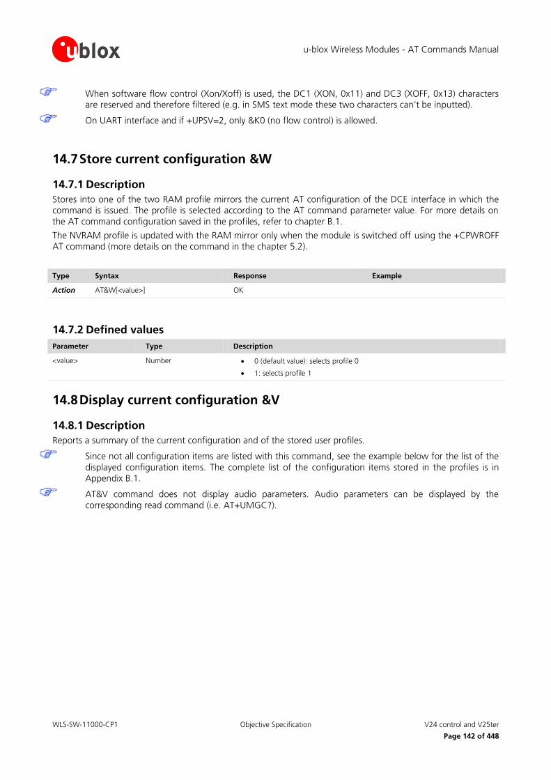
u-blox Wireless Modules - AT Commands Manual
WLS-SW-11000-CP1 Objective Specification V24 control and V25ter
Page 142 of 448
When software flow control (Xon/Xoff) is used, the DC1 (XON, 0x11) and DC3 (XOFF, 0x13) characters are reserved and therefore filtered (e.g. in SMS text mode these two characters can’t be inputted).
On UART interface and if +UPSV=2, only &K0 (no flow control) is allowed.
14.7 Store current configuration &W
14.7.1 Description
Stores into one of the two RAM profile mirrors the current AT configuration of the DCE interface in which the command is issued. The profile is selected according to the AT command parameter value. For more details on
the AT command configuration saved in the profiles, refer to chapter B.1.
The NVRAM profile is updated with the RAM mirror only when the module is switched off using the +CPWROFF AT command (more details on the command in the chapter 5.2).
Type Syntax Response Example
Action AT&W[<value>] OK
14.7.2 Defined values
Parameter Type Description
<value> Number 0 (default value): selects profile 0
1: selects profile 1
14.8 Display current configuration &V
14.8.1 Description
Reports a summary of the current configuration and of the stored user profiles.
Since not all configuration items are listed with this command, see the example below for the list of the
displayed configuration items. The complete list of the configuration items stored in the profiles is in Appendix B.1.
AT&V command does not display audio parameters. Audio parameters can be displayed by the
corresponding read command (i.e. AT+UMGC?).

u-blox Wireless Modules - AT Commands Manual
WLS-SW-11000-CP1 Objective Specification V24 control and V25ter
Page 143 of 448
Type Syntax Response Example
Action AT&V ACTIVE PROFILE:
List of commands stored in the active profile with the related values
STORED PROFILE 0:
List of commands stored in the profile 0 with the related values
STORED PROFILE 1:
List of commands stored in the profile 1 with the related values
OK
ACTIVE PROFILE: &C1, &D1, &S1, &K3, E1, Q0, V1, X4, S00:000, S02:043, S03:013, S04:010, S05:008, S07:060, +CBST:007, 000, 001, +CRLP:061, 061, 048, 006, +CR:000, +CRC:000, +IPR:0, +COPS:0,0,FFFFF, +ICF:3,1, +UPSV: 0, +CMGF:0, +CNMI:1,0,0,0,0, +USTS: 0
STORED PROFILE 0: &C1, &D1, &S1, &K3, E1, Q0, V1, X4, S00:000, S02:043, S03:013, S04:010, S05:008, S07:060, +CBST:007, 000, 001, +CRLP:061, 061, 048, 006, +CR:000, +CRC:000, +IPR:0, +COPS:0,0,FFFFF, +ICF:3,1, +UPSV: 0, +CMGF:0, +CNMI:1,0,0,0,0, +USTS: 0
STORED PROFILE 1: &C1, &D1, &S1, &K3, E1, Q0, V1, X4, S00:000, S02:043, S03:013, S04:010, S05:008, S07:060, +CBST:007, 000, 001, +CRLP:061, 061, 048, 006, +CR:000, +CRC:000, +IPR:0, +COPS:0,0,FFFFF, +ICF:3,1, +UPSV: 0, +CMGF:0, +CNMI:1,0,0,0,0, +USTS: 0
OK
14.9 Designate a default reset profile &Y
14.9.1 Description
Selects which NVRAM-profile will be loaded at the next power on. The AT commands configuration from the
loaded profile will be separately applied to each attached interface. At run time each interface will own the
configuration as described in chapter B.1. An error is returned if <value> is greater then 2, or NVRAM is not installed or is not operational.
For more details on the commands stored in the profiles, refer to chapter B.1.
Type Syntax Response Example
Action AT&Y[<value>] OK
14.9.2 Defined values
Parameter Type Description
<value> Number 0 (default value): selects profile 0
1: selects profile 1
2: selects the factory-programmed settings
14.10 Request identification information I
14.10.1 Description
Causes the DCE to transmit one or more lines of information text followed by a final result code.

u-blox Wireless Modules - AT Commands Manual
WLS-SW-11000-CP1 Objective Specification V24 control and V25ter
Page 144 of 448
Type Syntax Response Example
Action ATI[<value>] <string>
OK
LISA-U120-00S-00
OK
14.10.2 Defined values
Parameter Type Description
<value> Number Range 0-9; for each value a text will be displayed
0 (default value): provide the product type number of the module
1-9: reserved
14.11 Request manufacturer Identification +GMI
14.11.1 Description
Text string identifying the manufacturer.
Type Syntax Response Example
Action AT+GMI <manufacturer>
OK
u-blox
OK
14.11.2 Defined values
Parameter Type Description
<manufacturer> String Manufacturer name
14.12 Request model identification +GMM
14.12.1 Description
Text string identifying the model identification.
Type Syntax Response Example
Action AT+GMM <model>
OK
LISA-U120
OK
14.12.2 Defined values
Parameter Type Description
<model> String Name of model
14.13 Request revision identification +GMR
14.13.1 Description
Returns the firmware version of the module.

u-blox Wireless Modules - AT Commands Manual
WLS-SW-11000-CP1 Objective Specification V24 control and V25ter
Page 145 of 448
Type Syntax Response Example
Action AT+GMR <version>
OK
11.40
OK
14.13.2 Defined values
Parameter Type Description
<version> String Firmware version
14.14 Request product serial number identification +GSN
14.14.1 Description
Returns the IMEI (International Mobile Equipment Identity) of the MT.
Type Syntax Response Example
Action AT+GSN <IMEI>
OK
355306040004097
OK
Test AT+GSN=? OK
14.14.2 Defined values
Parameter Type Description
<IMEI> String IMEI
14.15 DTE-DCE character framing +ICF
14.15.1 Description
Sets the local serial port start-stop (asynchronous) character framing which is used in information interchange between DCE and DTE. Value 0 corresponds to the auto-detect case (if autobauding is supported).
The following restrictions must be reminded as follows:
o If a data frame format refers to a frame without parity (ex. Format 3), the command is
accepted, but the parity value is ignored; it is returned by the AT+ICF? command (and displayed
by AT&V) but it has no meaning
o The settings of the command are ignored when the AT command interface runs on the USB
port or on the SPI interface
Type Syntax Response Example
Set AT+ICF=[<format>[,<parity>]] OK AT+ICF=3,1
OK
Read AT+ICF? +ICF: <format>,<parity>
OK
+ICF: 3,1
OK
Test AT+ICF=? +ICF: (list of supported <format>s),(list of supported <parity>s)
OK
+ICF: (0-3,5),(0-1)
OK

u-blox Wireless Modules - AT Commands Manual
WLS-SW-11000-CP1 Objective Specification V24 control and V25ter
Page 146 of 448
14.15.2 Defined values
Parameter Type Description
<format> Number 0: auto detect
1: 8 data 2 stop
2: 8 data 1 parity 1 stop
3: 8 data 1 stop
5: 7 bit, 1 parity, 1 stop
<parity> Number 0: odd
1: even
LISA-U1 / LISA-U2 series automatic frame recognition
Automatic frame recognition is not supported by LISA-U1 series and LISA-U200-00S version (<format>
cannot be set to 0).
If the parameters are omitted they are set to <format> = 3 and <parity> = 1.
If automatic baud rate detection (+IPR is set to 0) is enabled in the NVRAM profile, the +ICF setting is not applied at start-up, and the read command returns the current detected frame format only after detection.
Automatic frame recognition is present together with automatic baud rate recognition
Since automatic frame recognition is implemented as “one shot”, the AT+ICF=0 answers OK but does not switch the system to the automatic frame recognition and it doesn’t take any actions. The read command
always returns the current value of the frame format and the value of +ICF in the active profile is not
changed
If automatic frame recognition is enabled, the read command returns the current (detected) frame setting
even if the current active profile provides +ICF=0. To change the frame format at the next module power on
issue the set command with the new setting and save it in the profile
The detectable frame configurations are: 7E1, 7O1, 8N1, 8E1, 8O1
The stop bit number cannot be automatically recognized i.e. if the system is switched from the 8N2 to the
autodetect feature and a 1 stop bit frame is provided at the serial port, the system can behave unpredictably
LEON-G100 / LEON-G200 / SARA-G350 series automatic frame recognition
If the parameters are omitted they are set to <format> = 0 and <parity> = 0.
Frame recognition can only be present in conjunction with autobauding recognition, i.e. the AT+ICF=0
command is effective only if AT+IPR is set to 0. In this case the AT+ICF? returns a 0 value.
Outside the autobauding conditions the AT+ICF=0 answers OK but does not switch the system to automatic frame recognition and it doesn’t take any actions. In this scenario the AT+ICF? command returns the current
value of the frame format. The AT+IPR=0 command instead forces the AT+ICF to 0
Under autobauding conditions, the AT+ICF command provided with a value different than 0 answers ERROR since it is not possible to specify a frame type in these autodetect conditions
The stop bit number cannot be automatically recognized i.e. if the system is switched from the 8N2 to the
autodetect feature and an 1 stop bit frame is provided at the serial port, the system can behave unpredictably
14.16 DTE-DCE local flow control +IFC
14.16.1 Description
Controls the operation of local flow control between DTE and DCE used when data are sent or received.

u-blox Wireless Modules - AT Commands Manual
WLS-SW-11000-CP1 Objective Specification V24 control and V25ter
Page 147 of 448
The command setting provides the error message “+CME ERROR: operation not allowed” when the AT command interface runs on the USB port or on the SPI interface.
The software flow control (Xon/Xoff) setting is not allowed on the USB port, on the SPI interface and on
a multiplexer channel.
SW flow control (Xon/Xoff) activation is only allowed in case of text transmission: binary data cannot be transmitted because it may contain the special flow control characters (Xon/Xoff).
When Software flow control (Xon/Xoff) is used, the DC1 (XON, 0x11) and DC3 (XOFF, 0x13) characters
are reserved and therefore filtered (e.g. in SMS text mode these two characters can’t be inputted).
On UART interface, if +UPSV is set to 2, only +IFC=0,0 (no flow control) is allowed.
Type Syntax Response Example
Set AT+IFC=[<DCE_by_DTE> [,<DTE_by_DCE>]]
OK AT+IFC=2,2
OK
Read AT+IFC? +IFC: <DCE_by_DTE>, <DTE_by_DCE>
OK
+IFC: 2,2
OK
Test AT+IFC=? +IFC: (list of supported <DCE_by_DTE>),(list of supported <DTE_by_DCE>s)
OK
+IFC: (0-2),(0-2)
OK
14.16.2 Defined values
Parameter Type Description
<DCE_by_DTE> Number 0: none
1: DC1/DC3 on circuit 103 (XON/XOFF)
2 (default value): circuit 105 (RTS)
<DTE_by_DCE> Number 0: none
1: DC1/DC3 on circuit 104 (XON/XOFF)
2 (default value): circuit 106 (CTS)
<DCE_by_DTE> and <DTE_by_DCE> must be provided with same value in pairs (only (0,0), (1,1) and
(2,2) are allowed. The other combinations are not allowed and the error message “+CME ERROR: operation not allowed” is returned).
14.17 Set flow control \Q
14.17.1 Description
Controls the operation of local flow control between DTE and DCE. Used when data is sent or received.
The command setting provides the error message “+CME ERROR: operation not allowed” when the AT
command interface runs on the USB port or on the SPI interface.
The software flow control (Xon/Xoff) setting is not allowed on the USB port, on the SPI interface and on
a MUX channel.
SW flow control (Xon/Xoff) activation is only allowed in case of text transmission: binary data cannot be transmitted because it may contain the special flow control characters (Xon/Xoff).
When Software flow control (Xon/Xoff) is used, the DC1 (XON, 0x11) and DC3 (XOFF, 0x13) characters
are reserved and therefore filtered (e.g. in SMS text mode these two characters can’t be inputted).

u-blox Wireless Modules - AT Commands Manual
WLS-SW-11000-CP1 Objective Specification V24 control and V25ter
Page 148 of 448
On UART interface, if +UPSV is set to 2, only \Q0 (no flow control) is allowed.
Type Syntax Response Example
Set AT\Q[<value>] OK AT\Q3
OK
14.17.2 Defined values
Parameter Type Description
<value> Number 0: no flow control
1: DC1/DC3 on circuit 103 and 104 (XON/XOFF)
3 (default value): DCE_by_DTE on circuit 105 (RTS) and DTE_by_DCE on circuit 106 (CTS)
14.18 Fixed DTE rate +IPR
14.18.1 Description
Specifies the data rate at which the DCE accepts commands on UART interface. The full range of data rates depends on HW or other criteria.
When supported, the autobauding feature allows baud rate recognition by the DCE in the Offline Command
State.
The settings of the command are ignored when the AT command interface runs on the USB port or on
the SPI interface. The DCE sends the string “OK” but the command will have no effect.
Type Syntax Response Example
Set AT+IPR=[<rate>] OK AT+IPR=9600
OK
Read AT+IPR? +IPR: <rate>
OK
+IPR: 9600
OK
Test AT+IPR=? +IPR: (list of supported autodetectable <rate> values)[,(list of fixed only <rate> values)]
OK
+IPR: (0,2400,4800,9600,19200,38400, 57600,115200),()
OK
14.18.2 Defined values
Parameter Type Description
<rate> Number Baud rate
0: autobauding
1200, 2400, 4800, 9600, 19200, 38400, 57600, 115200, 230400, 460800, 921600
On LEON-G100 / LEON-G200 series <rate>= 1200, <rate>= 230400, <rate>=460800 and <rate>=
921600 cannot be set as fixed rate.
u-blox Wireless Modules - AT Commands Manual
WLS-SW-11000-CP1 Objective Specification V24 control and V25ter
Page 149 of 448
On SARA-G350 series <rate>= 1200, <rate>= 230400 cannot be set as fixed rate, while <rate>=460800 and <rate>= 921600 are not supported.
On LISA-U1 series and LISA-U200-00S version <rate>= 921600 cannot be set as fixed rate.
LISA-U1 / LISA-U2 series autobauding description
On LISA-U1 series and LISA-U200-00S version:
o Automatic baud rate detection is not implemented (<rate>=0 is not supported)
o The default value for <rate> is 115200
Only one shot automatic baud rate detection is implemented. If enabled, the module provides autobauding
capability only at module start-up, and keeps it active until a first recognition is completed. Later on, it works at the fixed baudrate (the detected one).
If automatic baud rate detection is set in the active memory profile, the baud rate is detected once at the
module power on
The factory-programmed setting has automatic baud rate detection enabled (<rate> value is 0)
Since autobauding is implemented as “one shot” autobauding, any setting of +IPR=0 should be avoided;
the only exception is in case the autobauding setting has been replaced by a fixed rate setting in the stored NVRAM profile. In this case the module has started without autobauding and the host needs to reactivate it
If the module starts with the autobauding active, after the detection, the +IPR read command returns the
detected baudrate, while the +IPR value in the active profile (displayed as result of AT&V) doesn’t change (it continues to be 0, otherwise the +IPR setting should be changed every time an AT parameter is changed and
the profile saved in the NVRAM via the AT&W command). As a result, the only way to change the +IPR value
in the profile is by issuing an +IPR set command (e.g. AT+IPR=115200 sets a fixed rate on the UART and determines a start-up at a fixed rate of 115200 b/s in case the active profile is saved via AT&W)
After AT+IPR=0, the run-time configuration of the AT interface is updated (AT&V shows the new setting in
the active profile), but the setting is effective only at the next start-up (if and only if the active configuration is saved in the NVRAM)
As a consequence of the previous point, if AT+IPR=0 the +IPR read command continues to return the
current set baudrate (and not the 0 value). This is an exception and it creates a discrepancy between the value in the profile and the value returned by the +IPR read command, but it allows autobauding
re-activation and a coherent result of the +IPR read command
Autobauding values which can be detected are 1200, 2400, 4800, 9600, 19200, 38400, 57600, 115200, 230400 b/s. This means that baudrate 460800 and 921600 b/s cannot be automatically detected by DCE
and must only be set as a fixed rate (via +IPR AT command). AT commands provided with a baudrate other than the stated values lead to unpredictable results
If the system starts in autobauding (i.e. the +IPR is 0) the first “at” sequence provided to the module detects
the baudrate. For example the first command sent from the DTE at any rate can be: AT+CPIN="1234"
Characters different than “AT” are ignored during the baud rate detection since the hardware detection
sequence is triggered on the “at” or “AT” sequence. “At” or “aT” sequences are invalid: both detection
characters must be small or capital:
o The echo is produced or not according to ATE configuration. The echo is only produced for a
valid detection string and only after the detection completion, that is there will be a one
character delay between the received characters and the echo generation (the echo will start only after “at” or “AT” reception)
o The echo is always “AT” regardless of the detection string sent by DTE
o The module generates a response for the DTE once autobauding detection is successful, the command has been accepted and the command response is available. Therefore, even if the
detection was actually successful a certain amount of time before, it is only possible to assume
that the detection phase was successful after a response

u-blox Wireless Modules - AT Commands Manual
WLS-SW-11000-CP1 Objective Specification V24 control and V25ter
Page 150 of 448
o If no response is received by the DTE after some time, it must retry (the timeout value should be adjustable inside the DTE application). In any case it is suggested to use a very simple command
as the first command, for which the execution time is short and almost constant (e.g. ATE)
If UART power saving is enabled, the command for the baud rate detection should be sent to the DTE before the module enters idle mode for the first time
Autobauding result can be unpredictable with spurious characters if power saving is entered and the flow control is disabled. If the hardware flow control is present, the DTE can be synchronized with the power
saving cycle through the module CTS line i.e. the delivery of the “AT” sequence during the module wake up
can be granted by the DTE and power saving can be exited correctly. Disable the power saving if no hardware flow control is set at start up
If automatic baud rate detection is active, greeting messages or URCs before baud rate detection are not
sent but buffered. They are sent as first data at the detected baud rate as soon as detection is completed (before any echo of the command or response). The greeting message is sent at the specified baud rate only
when the baudrate setting in the NVRAM is other than autobauding
Data rate 0 also affects the AT+ICF command. Carefully read the description of the AT+ICF command (chapter 14.15) for further limitations
If the parameter is omitted <rate> value is set to 115200
LEON-G100 / LEON-G200 / SARA-G350 series autobauding description
On LEON-G100 / LEON-G200 / SARA-G350 series the following notes related to autobauding must be reminded:
The DCE can start in autobauding (necessary to program the NVM with the baudrate parameter set to 0) or the autobauding can be enabled with the AT+IPR=0 command if the DCE started with a fixed rate
Autobauding values which can be discovered are the same of the fixing case i.e. 2400, 4800, 9600, 19200,
38400, 57600, 115200 b/s. Although values outside this set will be detected (for ex. 1200 b/s or 230400 b/s), AT commands provided with a baudrate other than values declared, leads to unpredictable
results
If the system starts in autobauding (i.e. the +IPR is 0) the first “at” sequence provided to the module detects the baudrate. For example the first command sent from the DTE at any rate can be: AT+CPIN="1234"
Characters different than AT are ignored during the baud rate detection since the hardware detection sequence is triggered on the “at” or “AT” sequence. “At” or “aT” sequences are invalid too, both of the
detection characters must be small or capital
Power saving is exited at the ’A‘ (or ’a‘) character of the autobauding sequence; power save state is re-entered again when the power saving timeout is elapsed, regardless if the baud detection is complete or
not. The ’T‘ (or ’t‘) character doesn’t reset the power saving timer; as a result if the detection completion
character is sent outside power save condition, it doesn’t force to stay out of power saving state for the number of frames of power saving timer
Autobauding result can be unpredictable with spurious characters if the power saving is entered and the
flow control is disabled. If the hardware flow control is present, the DTE can be synchronized with the power saving cycle through the module CTS line i.e. the delivery of the “AT” sequence during the module
awake can be granted by the DTE and the power saving can be exited in the proper way. It is recommended
to disable the power saving if no hardware flow control is used
Data rate 0 affects the AT+ICF command too which value is automatically switched to the 0 value. Read
carefully the description of the AT+ICF command for further limitations
The default value for <rate> is 0

u-blox Wireless Modules - AT Commands Manual
WLS-SW-11000-CP1 Objective Specification V24 control and V25ter
Page 151 of 448
14.19 System can Return to on-line data state O
14.19.1 Description
Causes the DCE to return to online data state and issue a CONNECT or CONNECT <text> (based on ATX command) result code on DTE. It is the complementary command to the escape sequence, or to the other
actions (DTR ON to OFF transition, see table in 14.4.4) that cause the DCE to switch from online data state to
online command state.
ATO command is used to resume both circuit-switched and packet-switched data call. The resume is only
possible if the PPP L2 protocol is used.
Type Syntax Response Example
Action ATO <response> ATO
CONNECT
14.19.2 Defined values
Parameter Type Description
<response> String CONNECT
NO CARRIER: the online data state can’t be resumed
The command provides an error message (“+CME ERROR: operation not allowed” if +CMEE is set to 2)
in the following cases:
o The DCE is not in online command state
o It is issued on a DCE different from the one in online command state
14.20 Escape character S2
14.20.1 Description
Controls the decimal value of the ASCII character used as the escape character. A value over 127 disables the
escape process, i.e. no escape character will be recognized. The escape sequence contains three escape characters e.g. “+++”.
Type Syntax Response Example
Set ATS2=<value> OK ATS2=43
OK
Read ATS2? <value>
OK
043
OK
14.20.2 Defined values
Parameter Type Description
<value> Number Range 1 to 255. Answer to Read command is in “xxx” format. Default value: 043 (ASCII ‘+’).
On LEON-G100 / LEON-G200 / SARA-G350 series <value> value is not mandatory.

u-blox Wireless Modules - AT Commands Manual
WLS-SW-11000-CP1 Objective Specification V24 control and V25ter
Page 152 of 448
Table 3 shows the ATS2 command handling for different data call scenarios.
Data call command L2 protocol Description ATS2 behavior
AT+CGDATA="M-HEX",1 HEX u-blox specific Escape sequence detection is only done for +++ (plus carriage return). ATS2 is not effective. No timing constraints.
AT+CGDATA="M-RAW_IP",1 RAW-IP PSD call: Transfer IP packet directly Break detection is not supported
AT+CGDATA="PPP",1 PPP PSD call: Same of ATD*99***1# (e.g. dial up)
Escape sequence detection is only done for ~+++. ATS2 is not effective.
There is not a timing constrain (see S12 command) for ~+++ (+++ is incapsulated in a PPP frame)
ATD1234 CSD call The command is effective if issued in both command and online command mode
AT+USODL=0 PSD call: Direct Link mode The command is effective
AT+USOWR=0,32 PSD call:AT socket (not transparent) Break detection is not supported
Table 3: ATS2 handling for different data call scenarios
14.21 Command line termination character S3
14.21.1 Description
Sets a value representing the decimal IRA5 value of the character recognized by the DCE from the DTE, to
terminate the incoming command line. It is also generated by the DCE as part of the header, trailer and terminator for result codes and information text, along with the S4 setting.
Type Syntax Response Example
Set ATS3=<value> OK ATS3=13
OK
Read ATS3? <value>
OK
013
OK
14.21.2 Defined values
Parameter Type Description
<value> Number Range 0 to 127. Answer to Read command is in “xxx” format. Default value: 013 (ASCII carriage return (CR, IRA5 0/13)).
On LEON-G100 / LEON-G200 / SARA-G350 series <value> value is not mandatory.
14.22 Response formatting character S4
14.22.1 Description
Sets a value representing the decimal IRA5 value of the character generated by the DCE as part of the header, trailer and terminator for result codes and information text, along with the S3 setting.

u-blox Wireless Modules - AT Commands Manual
WLS-SW-11000-CP1 Objective Specification V24 control and V25ter
Page 153 of 448
Type Syntax Response Example
Set ATS4=<value> OK ATS4=10
OK
Read ATS4? <value>
OK
010
OK
14.22.2 Defined values
Parameter Type Description
<value> Number Range 0 to 127. Answer to Read command is in “xxx” format. Default is 10 (line feed (LF, IRA5 0/10))
On LEON-G100 / LEON-G200 / SARA-G350 series <value> value is not mandatory.
14.23 Command line editing character S5
14.23.1 Description
Sets a value representing the decimal IRA5 character recognized by the DCE as a request to delete from the command line the immediately preceding character.
Type Syntax Response Example
Set ATS5=<value> OK ATS5=8
OK
Read ATS5? <value>
OK
008
OK
14.23.2 Defined values
Parameter Type Description
<value> Number Range 0 to 127. Answer to Read command is in “xxx” format. Default value: 8 (ASCII backspace (BS, IRA5 0/8))
On LEON-G100 / LEON-G200 / SARA-G350 series <value> value is not mandatory.
14.24 Pause before blind dialling S6
14.24.1 Description
Specifies the time in seconds that the DCE waits between connecting to the line and dialling, when dial tone is
not implemented or enabled. The command is not applicable for signal based mobile phone software.
Type Syntax Response Example
Set ATS6=<value> OK ATS6=2
OK

u-blox Wireless Modules - AT Commands Manual
WLS-SW-11000-CP1 Objective Specification V24 control and V25ter
Page 154 of 448
Type Syntax Response Example
Read ATS6? <value>
OK
002
OK
14.24.2 Defined values
Parameter Type Description
<value> Number Range 2 - 10. Answer to Read command is in “xxx” format. Default 2 s
On LEON-G100 / LEON-G200 / SARA-G350 series <value> value is not mandatory.
14.25 Connection completion timeout S7
14.25.1 Description
Specifies time in seconds, that the DCE shall allow between either answering a call or completion of dialling and establishment of a connection with a remote site.
Type Syntax Response Example
Set ATS7=<value> OK ATS7=30
OK
Read ATS7? <value>
OK
060
OK
14.25.2 Defined values
Parameter Type Description
<value> Number Range 1 - 255. Answer to Read command is in “xxx” format. Default 60 s
On LEON-G100 / LEON-G200 / SARA-G350 series <value> value is not mandatory.
14.26 Command dial modifier time S8
14.26.1 Description
Specifies time in seconds, that the DCE shall pause, during dialling, when a ‘,’ dial modifier is encountered in a
dial string, the command has no effect.
Type Syntax Response Example
Set ATS8=<value> OK ATS8=4
OK
Read ATS8? <value>
OK
002
OK

u-blox Wireless Modules - AT Commands Manual
WLS-SW-11000-CP1 Objective Specification V24 control and V25ter
Page 155 of 448
14.26.2 Defined values
Parameter Type Description
<value> Number Range 0 - 255. Answer to Read command is in “xxx” format. Default: 2
On LEON-G100 / LEON-G200 / SARA-G350 series <value> value is not mandatory.
14.27 Automatic disconnect delay S10
14.27.1 Description
Specifies time in tenth of a second, that the DCE will remain connected to the line after the DCE has indicated
the absence of received line signal. Not supported for GSM but OK returned.
Type Syntax Response Example
Set ATS10=<value> OK ATS10=30
OK
Read ATS10? <value>
OK
030
OK
14.27.2 Defined values
Parameter Type Description
<value> Number Range 1 – 254. Default: 1
On LEON-G100 / LEON-G200 / SARA-G350 series <value> value is not mandatory.
14.28 Escape prompt delay (EPD) S12
14.28.1 Description
Defines the maximum period, in fiftieths of a second, allowed between the reception of the last character of the
sequence of three escape characters from the DTE and the sending of the OK result code to the DTE. If any characters are detected during this time, the OK will not be sent.
Furthermore, the timeout is:
The minimum period, before the first character reception of the three escape character sequence, during which no other character must be detected to accept it as valid first character
The maximum period allowed between receipt of first, or second, character of the three escape character
sequence and receipt of the next
The minimum period, after the last character reception of the three escape character sequence, during
which no other character must be detected to accept the escape sequence as a valid one
Type Syntax Response Example
Set ATS12=<value> OK ATS12=80
OK

u-blox Wireless Modules - AT Commands Manual
WLS-SW-11000-CP1 Objective Specification V24 control and V25ter
Page 156 of 448
Type Syntax Response Example
Read ATS12? <value>
OK
050
OK
14.28.2 Defined values
Parameter Type Description
<value> Number Range 0 - 255. Answer to Read command is in “xxx” format. Default: 50 (1 s)
On LEON-G100 / LEON-G200 / SARA-G350 series <value> value is not mandatory.
14.29 Command echo E
14.29.1 Description
Controls whether or not the MT echoes characters received from the DTE during command state.
Type Syntax Response Example
Set ATE[<value>] OK ATE1
OK
14.29.2 Defined values
Parameter Type Description
<value> Number 0: echo off
1 (default value): echo on
14.30 Result code suppression Q
14.30.1 Description
Determines if DCE transmits result codes to the DTE or not. When result codes are being suppressed, no portion
of any intermediate, final or URC is transmitted. Information text transmitted in response to commands is not affected by this setting.
Type Syntax Response Example
Set ATQ[<value>] OK ATQ1
OK
14.30.2 Defined values
Parameter Type Description
<value> Number 0 (default value): DCE transmits result codes
1: Result codes are suppressed and not transmitted

u-blox Wireless Modules - AT Commands Manual
WLS-SW-11000-CP1 Objective Specification V24 control and V25ter
Page 157 of 448
14.31 DCE response format V
14.31.1 Description
Control the contents of the header and trailer transmitted with result codes and information responses. It also determines whether result codes are transmitted in a numeric form or an alphabetic (or verbose) form. The text
portion of information responses is not affected by this setting. The effect of V setting on response formats is
described below:
Format for information response:
o for V0: <text><CR><LF>
o for V1: <CR><LF><text><CR><LF>
Format for result codes:
o for V0: <numeric code><CR>
o for V1: <CR><LF><verbose code><CR><LF>
Type Syntax Response Example
Set ATV[<value>] OK ATV1
OK
14.31.2 Defined values
Parameter Type Description
<value> Number 0: DCE transmits limited headers, trailers and numeric text
1 (default value): DCE transmits full headers, trailers and verbose response text
14.32 Result code selection and call progress monitoring control X
14.32.1 Description
In a CS data call, determines how the DCE transmits to the DTE the CONNECT result code.
Type Syntax Response Example
Set ATX[<value>] OK ATX1
OK
14.32.2 Defined values
Parameter Type Description
<value> Number 0: CONNECT result code is given upon entering online data state;
1-4: CONNECT <speed> result code is given upon entering online data state; (4 is the default value)
<speed> Number Transfer speed for CSD calls configured via the CBST command

u-blox Wireless Modules - AT Commands Manual
WLS-SW-11000-CP1 Objective Specification SIM toolkit
Page 158 of 448
15 SIM toolkit
15.1 Introduction
SIM toolkit processing supports two modes: dedicated and raw. Only one mode can be enabled and function at
a time.
In dedicated mode, these commands return the output after decoding; in raw mode they deliver the raw output.
The commands in this section only properly work if the SIM toolkit interface has been activated by the DTE.
Otherwise the SIM-toolkit processing will be blocked.
The activation of the SIM toolkit interface can be done by:
AT+CFUN=6 for enabling dedicated mode
AT+CFUN=9 for enabling raw mode
After the activation of the SIM toolkit interface, the setup menu may be displayed via URC +STKPRO when available from the SIM (immediately or after PIN insertion).
For more details on the command description and parameters, refer to 3GPP TS 51.014 [44].
If an AT command related to dedicated mode is used when raw mode is enabled, an error message (“+CME ERROR: operation not allowed” if +CMEE is set to 2) is returned and vice versa.
15.2 Proactive command +STKPRO
15.2.1 Description
The test command displays the list of the proactive commands that need a response from the user/application
via +STKTR command. Only the test command syntax is allowed.
During STK transactions, every proactive command is displayed using the URC +STKPRO.
Type Syntax Response Example
Test AT+STKPRO=? +STKPRO: (list of supported <proactive_cmd>s)
OK
+STKPRO: (01,05,16,17,18,19,20,21,32,33,34,35,36,37,38,40,53)
OK
URC Generic syntax:
+STKPRO: <proactive_cmd>,…
Refresh:
+STKPRO: 01,<type>,<number of files>,<files>
Set up event list:
+STKPRO: 05,<event_list>
Set up call:
+STKPRO: 16,<number>,<subaddr>,<type>,<alpha_1>,<icon_id1>,<alpha_2>,<icon_id2>
Send SS:

u-blox Wireless Modules - AT Commands Manual
WLS-SW-11000-CP1 Objective Specification SIM toolkit
Page 159 of 448
Type Syntax Response Example
+STKPRO: 17,<ss_data>,<alpha>,<icon_id>,<ref_number>
Send USSD:
+STKPRO: 18,<dcs>,<hex_string>,<alpha>,<icon_id>,<ref_number>
Send SMS:
+STKPRO: 19,<alpha>,<icon_id>,<ref_number>
Send DTMF:
+STKPRO. 20,<alpha>,<icon_id>,<dtmf_string>
Launch browser:
+STKPRO: 21,<URL>,<alpha>,<icon_id>
Play tone:
+STKPRO: 32,<tone>,<unit>,<interval>,<alpha>,<icon_id>
Display text:
+STKPRO: 33,<type>,<dcs>,<hex_string>,<icon_id>,<imm_resp>
Get inkey:
+STKPRO: 34,<type>,<dcs>,<hex_string>,<icon_id>
Get input:
+STKPRO: 35,<type>,<dcs>,<hex_string>,<max_rsp_len>,<min_rsp_len>,<default_text>,<icon_id>
Select item:
+STKPRO: 36,<type>,<alpha>,<item_id>,<total_items>,<item_text>,<next_action>,<default_item>
Set up menu
+STKPRO: 37,<type>,<alpha>,<item_id>,<total_items>,<item_text>,<next_action>
Provide local info:
+STKPRO: 38,<type>
Set up idle mode text:
+STKPRO: 40,<dcs>,<hex_string>,<icon_id>
Language notification:
+STKPRO: 53,<language>

u-blox Wireless Modules - AT Commands Manual
WLS-SW-11000-CP1 Objective Specification SIM toolkit
Page 160 of 448
15.2.2 Defined values
Parameter Type Description
<alpha>, <alpha_1>, <alpha_2>
String Alpha identifier (used in several proactive commands, see ETSI TS 102 223 [51])
<default_text> String Default text for the GET INPUT command (see ETSI TS 102 223 [51])
<dcs> Number Data coding scheme
<default_item> Number Indication of the default item (see ETSI TS 102 223 [51])
<dtmf_string> String DTMF tones coded in BCD (same format as the Dialling number string defined for EFADN in GSM TS 11.11 [18])
<event list> Number 00: MT call
01: Call connected
02: Call disconnected
03: Location status
04: User activity
05: Idle screen available
06: Card reader status
07: Language selection
08: Browser termination
09: Data available
0A: Channel status
0B: Access Technology Change
0C: Display parameters changed
0D: Local connection
0E: Network Search Mode Change
0F: Browsing status
<hex_string> String Hexadecimal string (the coding is specified in the <dcs> parameter)
<icon_id>,
<icon_id1>,
<icon_id2>
String Icon identifier, set to 0 since no graphical interface is provided
<interval> Number Time duration in number of units
<imm_resp> Number Immediate response
<item_id> Number identifier of an item within a list
<item_text> String text string of item
<language> String 2 bytes string indicating the language
<max rsp len> Number Maximum response length
<min rsp len> Number Minimum response length
<next_action> Number Used only in menu related proactive commands (“set up menu” and “select item”) for each item. It gives the possible actions that will be initiated by the SIM Card in case of selection by the user (see ETSI TS 102 223 [51])
<number> String Called party number
<proactive_cmd> Number 01: refresh
05: set up event list
16: set up call
17: send SS
18: send USSD
19: send SMS

u-blox Wireless Modules - AT Commands Manual
WLS-SW-11000-CP1 Objective Specification SIM toolkit
Page 161 of 448
Parameter Type Description
20: send DTMF
21: launch browser
32: play tone
33: display text
34: get inkey
35: get input
36: select item
37: set up menu
38: provide local info
40: set up idle mode text
52: run AT command
53: language notification
<ref_number> Number Reference number
<subaddr> String Called party subaddr
<ss_data> String Supplementary services string
<type> Number Command qualifier
<tone> Number 01: dial tone
02: call subscriber busy
03: congestion
04: radio path acknowledge
05: radio path not available
06: error / special information
07: call waiting tone
08: ringing tone
10: general beep
11: positive acknowledgement tone
12: negative acknowledgement or error tone
<total_items> Number Total number of the menu items
<unit> Number 0: minutes
1: seconds
2: tenth of seconds
<URL> String URL to be loaded
<proactive_cmd>=52 is not supported by LEON-G100 / LEON-G200 / SARA-G350 modules.
15.3 Terminal response +STKTR
15.3.1 Description
Allows entering response to an SIM Toolkit proactive command which has been displayed by the URC +STKPRO.
If no response is entered, after a timeout of duration may range from 180 to 300 s, the modem sends an
autonomous terminal response to the SIM in order to complete the STK transaction; the result depends on the
pending proactive command and can be "Command performed successfully", "No response from user", "Command type not understood by ME" or "Command data not understood by ME" (see 3GPP TS
51.014 [44]).

u-blox Wireless Modules - AT Commands Manual
WLS-SW-11000-CP1 Objective Specification SIM toolkit
Page 162 of 448
AT+STKTR command must be entered always, in order to terminate the pending STK session at the MT-DTE interface, and to be able to enter additional STK commands.
The parameters to be entered depend on the proactive command:
+STKTR:01,<result>,[<add_result>] refresh
+STKTR:05,<result> set up event list
+STKTR:16,<result>,[<add_result>] set up call
+STKTR:17,<result>,<add_result>,[<reference_number>] send SS
+STKTR:18,<result>,<add_result>,[<reference_number>] send USSD
+STKTR:19,<result>,<add_result>,[<reference_number>] send SMS
+STKTR:20,<result>,[<add_result>] send DTMF
+STKTR:21:<result> launch browser
+STKTR:32,<result>,<add_result> play tone
+STKTR:33,<result>,<add_result> display text
+STKTR:34,<result>,<add_result>,0,<dcs>,<hex_string> get inkey
+STKTR:35,<result>,<add_result>,0,<dcs>,<hex_string> get input
+STKTR:36,<result>,<add_result>,0,<dcs>,<hex_string> select item
+STKTR:37,<result>,<add_result> set up menu
+STKTR:38,<type>,<language> provide local info (language setting)
+STKTR:40,<result>,<add_result> set up idle mode text
*0 stands for the obsolete parameter <last_cmd>.
Can be used only if the SIM toolkit interface is enabled in dedicated mode.
Type Syntax Response Example
Set AT+STKTR=<proactive_cmd>[,<type>][,<result>,<add_result>[,<reference_number>][,<last_cmd>][,<dcs>][,<hex string>]]
OK AT+STKTR=1,0
OK
Test AT+STKTR=? +STKTR: (list of supported <result> values)
OK
+STKTR: (01,05,16,17,18,19,20,21,32,33,34,35,36,37,38,40,53)
OK
15.3.2 Defined values
Parameter Type Description
<proactive_cmd> Number Decimal code indicates the command (refer +STKPRO command description - paragraph 15.2)
<result> Number 0: command performed successfully
1: command performed with partial comprehension
2: command performed with missing information
3: REFRESH performed with additional EFs read
4: command performed successfully, but requested icon could not be displayed
5: command performed but modified by call control by SIM
6: command performed successfully, limited service
7: command performed with modification

u-blox Wireless Modules - AT Commands Manual
WLS-SW-11000-CP1 Objective Specification SIM toolkit
Page 163 of 448
Parameter Type Description
16: proactive SIM session terminated by the user
17: backward move in the proactive SIM session requested by the user
18: no response from user
19: help information required by the user
20: USSD or SS transaction terminated by the user
32: MT currently unable to process command
33: network currently unable to process command
34: user did not accept call set-up request
35: user cleared down call before connection or network release
36: action in contradiction to the current timer state
37: interaction with call control by SIM, temporary problem
38: launch browser generic error code
48: command beyond MT’s capabilities
49: command type not understood by MT
50: command data not understood by MT
51: command number not known by MT
52: run AT command
53: SMS RP-ERROR
54: error, required values are missing
55: USSD return error
56: MultipleCard commands error, if class ’a’ is supported
57: interaction with call control by SIM or MO short message control by SIM, permanent problem
58: bearer independent protocol error (if class ’e‘ is supported)
<add_result> Number Additional information, required with specific result codes and/or proactive commands
<reference_number> Number Number containing the indicated reference number; this parameter can be used only in case of <proactive_cmd> related to SMS, SS, USSD
<dcs> Number Data coding scheme
<hex_string> String Default item (see item_id)
<language> String Pair of alpha-numeric characters, defined in ISO 639, here encoded as a Number, e.g. 25701 = 0x6465 = "de"
<last_cmd> Number Obsolete parameter, to be set to 0
<type> Number Command qualifier (used in case of <proactive_cmd>=38)
15.4 Envelope +STKENV
15.4.1 Description
Allows encoding and sending an STK envelope command to the SIM.
Can be used only if the SIM toolkit interface is enabled in dedicated mode.
Type Syntax Response Example
Set AT+STKENV=<envelope_cmd>,<opt_ENV_data1>, <opt_ENV_data2>
OK AT+STKENV=211,01
OK

u-blox Wireless Modules - AT Commands Manual
WLS-SW-11000-CP1 Objective Specification SIM toolkit
Page 164 of 448
Type Syntax Response Example
Test AT+STKENV=? +STKENV: (list of supported <envelope_cmd>
OK
+STKENV: 211,214
OK
15.4.2 Defined values
Parameter Type Description
<envelope_cmd> Number code 211 (0xD3): Menu selection (<opt_ENV_data1> shall specify the item identifier of startup menu list)
code 214 (0xD6): Event download (<opt_ENV_data1> shall specify the <event_list>, in which only one event can be included)
<opt_ENV_data1> Number Command code related parameters and can have the following values, depending on the chosen envelope command:
If <envelope_cmd>=211, “item identifier”
If <envelope_cmd>=214 (event list),
o 4: user activity
o 5: idle screen available
o 7: language selection
o 8: browser termination
<opt_ENV_data2> Number Meaning depends on the chosen envelope command:
If <envelope_cmd>=211, “help requested” with the following encoding:
o 0: help is not requested
o 1: help is requested
If <envelope_cmd>=214 and <opt_ENV_data1>=7, “currently used language in the DTE” (see AT+STKTR=38)
If <envelope_cmd>=214 and <opt_ENV_data1>=8, “provide the cause” with the following allowed values:
o 00: User Termination
o 01: Error Termination
15.5 Terminal profile +STKPROF
15.5.1 Description
Allows reading and changing the terminal profile (list of SIM Application Toolkit facilities supported by the
terminal, see ETSI TS 102 223 [51]) data stored in NVM and used only at SIM initialization. The SIM card may use
this information to filter the proactive commands sent to the module. This command does not actually remove/add any functionality from/to the module.
Can be used only if the SIM toolkit interface is enabled in dedicated mode.
Type Syntax Response Example
Set AT+STKPROF=<length>, <data> OK AT+STKPROF=2,"1F7F"
OK
Read AT+STKPROF? +STKPROF: <length>,<data>
OK
+STKPROF:17,"FFFFFFFF7F0300DF7F00000000010A0003"
OK
Test AT+STKPROF=? OK

u-blox Wireless Modules - AT Commands Manual
WLS-SW-11000-CP1 Objective Specification SIM toolkit
Page 165 of 448
15.5.2 Defined values
Parameter Type Description
<length> Number Length in bytes of data sent to DTE in <data>
<data> String Terminal profile data coded in hex format
<length> set to 0 forces a reset to the default terminal profile stored in the MT.
15.6 Call and short message control URC +STKCC
15.6.1 Description
The indication of the call control and short message control by SIM (see 3GPP TS 51.014 [44]) is performed using
the URC +STKCC.
Present only if the SIM toolkit interface is enabled in dedicated mode.
Type Syntax Response Example
URC +STKCC: <cc_command>,<res_val>,<alpha>,<param1>[,<sc_addr>,<ton_npi>, <dest_addr>]
+STKCC: 1,0,"Calling","+3913456890"
15.6.2 Defined values
Parameter Type Description
<cc_command> Number 1: set up call
2: send SS
3: send USSD
4: send SM
<res_val> Number Call control result value
00: Allowed, no modification
01: Not allowed
02: Allowed with modification
<alpha> String
<param1> String called party number if <cc_command>=1
supplementary service string if <cc_command>=2
USSD control string if <cc_command>=3
type of number and numbering plan if <cc_command>=4
<sc_addr> String Service centre address
<ton_npi> Number Type of number and numbering plan
<dest_addr> String Destination address

u-blox Wireless Modules - AT Commands Manual
WLS-SW-11000-CP1 Objective Specification SIM toolkit
Page 166 of 448
15.7 Proactive session status URC +STKCNF
15.7.1 Description
The STK proactive session status is displayed using this URC +STKCNF. The URC comes out after the AT+STKTR or the AT+STKENV command has been issued. Refer to chapter 15.3 and 15.4 for the related command
descriptions.
Present only if the SIM-toolkit interface is enabled in dedicated mode.
Type Syntax Response Example
URC +STKCNF: <proactive_cmd>,<result>,<add_result>,<sw1>
+STKCNF: 37,0,255,144
15.7.2 Defined values
Parameter Type Description
<proactive_cmd> Number Decimal code indicating the command that was finished (refer to +STKPRO command description 15.2); 129 (0x81) indicates the end of active session.
<result> Number Additional result code (refer to 3GPP 51.014 specification [44]]); if no additional information is available 255 (0xFF) is returned
<add_result> Number Additional result code; 255 (0xFF) is returned if no additional information is available
<sw1> Number Status of the last response
144 (0x90): command executed successfully
0: command to SIM was suppressed because of multiple terminal response or wrong client
For other responses see 3GPP TS 51.011 [18]
15.8 Raw Mode Envelope Download +SATE
15.8.1 Description
Sends the raw envelope data to the SIM.
Can be used only if the SIM toolkit interface is enabled in raw mode.
The command is not available on LISA-U1x0-00S versions.
Type Syntax Response Example
Set AT+SATE=<text> +SATE: <sw1>,<sw2>,<envelope_type>,<event_type>
OK
AT+SATE="d30782020181900101"
+SATE: 145,111,211,255
OK

u-blox Wireless Modules - AT Commands Manual
WLS-SW-11000-CP1 Objective Specification SIM toolkit
Page 167 of 448
15.8.2 Defined values
Parameter Type Description
<text> String Raw envelope data in Hex value
<sw1> Number Status of the last response
144 (0x90): command executed successfully
0: command to SIM was suppressed because of multiple terminal response or wrong client
For other responses see 3GPP TS 51.011
<sw2> Number Specifies the additional information depending on <sw1>
<envelope_type> Number 211 (0xD3): Menu selection
214 (0xD6): Event download
<event_type> Number If <envelope_type>=214 (event list),
4: user activity
5: idle screen available
7: language selection
8: browser termination
15.9 Proactive Command Indication in RAW Mode +SATI
15.9.1 Description
Communicates to the user the proactive command, in raw mode, coming from SIM.
The module expects a terminal response to be sent; the user shall respond with AT+SATR for sending the terminal response.
Can be used only if the SIM toolkit interface is enabled in raw mode.
The command is not available on LISA-U1x0-00S versions.
Type Syntax Response Example
URC +SATI: <text> +SATI: "D020810301250082028182050C53544B2D4A617661436172648F030141411E020001"
15.9.2 Defined values
Parameter Type Description
<text> String Raw proactive command data in Hex value
15.10 Proactive Command Indication in RAW Mode +SATN
15.10.1 Description
Sends the proactive command in raw mode to the user in case the module handles the proactive command.
For this URC, the module does not expect any terminal response from the user, since the TERMINAL RESPONSE
to SIM shall be sent internally.

u-blox Wireless Modules - AT Commands Manual
WLS-SW-11000-CP1 Objective Specification SIM toolkit
Page 168 of 448
Present only if the SIM toolkit interface is enabled in raw mode.
The command is not available on LISA-U1x0-00S versions.
Type Syntax Response Example
URC +SATN: <text> +SATN: "D01A810301100082028183050A63616C6C696E672E2E2E86038121F3"
15.10.2 Defined values
Parameter Type Description
<text> String Raw proactive command data in Hex value
15.11 Send Terminal Response in RAW Mode +SATR
15.11.1 Description
Used to send the terminal response when +SATI URC is received by the user. It sends the Terminal Response in
raw mode to the SIM.
Can be used only if the SIM toolkit interface is enabled in raw mode.
The command is not available on LISA-U1x0-00S versions.
Type Syntax Response Example
Set AT+SATR=<text> OK AT+SATR="810301240082028281830100900101"
OK
15.11.2 Defined values
Parameter Type Description
<text> String Raw terminal response data in Hex value
15.12 Terminal Response Confirm +SATF
15.12.1 Description
Provides the response to a terminal response (sent by the user or automatically by the module) from the SIM.
Present only if the SIM toolkit interface is enabled in raw mode.
The command is not available on LISA-U1x0-00S versions.
Type Syntax Response Example
URC +SATF: <sw1>,<sw2> +SATF: 144,0

u-blox Wireless Modules - AT Commands Manual
WLS-SW-11000-CP1 Objective Specification SIM toolkit
Page 169 of 448

u-blox Wireless Modules - AT Commands Manual
WLS-SW-11000-CP1 Objective Specification SIM toolkit
Page 170 of 448
15.12.2 Defined values
Parameter Type Description
<sw1> Number Status of the last response
144 (0x90): command successfully executed
0: command to SIM was suppressed because of multiple terminal response or wrong client
For other responses see 3GPP TS 51.011
<sw2> Number The second status byte specifies additional information depending on <sw1>
15.13 User confirmation for SET UP Call in RAW mode +SATD
15.13.1 Description
SATD Set command is used for USER CONFIRMATION required for SET UP CALL proactive command. User can
accept the call or reject the call.
SATD is used as response to +SATN URC sent to the user for SET UP CALL Proactive command.
Can be used only if the SIM toolkit interface is enabled in raw mode.
The command is not available on LISA-U1x0-00S versions.
Type Syntax Response Example
Set AT+SATD=<user_confirmation> OK AT+SATD=1
OK
Test AT+SATD=? +SATD: (list of supported <user_confirmation>’s)
OK
+SATD: (0,1)
OK
15.13.2 Defined values
Parameter Type Description
<user_confirmation> Number 0: reject the call
1: accept the call
15.14 Indication for Mo Call Control / Mo SMS Control +STKCTRLIND
15.14.1 Description
Lists the supported call/SMS control type.
+STKCTRLIND is an unsolicited indication for MO Call Control and MO SMS Control.
Present only if the SIM toolkit interface is enabled in raw mode.
The command is not available on LISA-U1x0-00S versions.

u-blox Wireless Modules - AT Commands Manual
WLS-SW-11000-CP1 Objective Specification SIM toolkit
Page 171 of 448
Type Syntax Response Example
Test AT+STKCTRLIND=? +STKCTRLIND: (range of supported <type>)
OK
+STKCTRLIND: (0-3)
OK
URC “set up call” type:
+STKCTRLIND: 0, <result>, <alpha_id>, <destination_address>, <destination_address_type>
“send SS” type:
+STKCTRLIND: 1, <result>, <alpha_id>, <destination_address>, <destination_address_type>
“send USSD” type:
+STKCTRLIND: 2, <result>, <alpha_id>, <dcs>, <data>
“send SMS” type:
+STKCTRLIND: 3,<result>,<alpha_id>,<destination_address>,<destination_address_type>, <service_center_address>,<service_center_address_type>
15.14.2 Defined values
Parameter Type Description
<type> Number 0: setup call
1: send SS
2: send USSD
3: send SMS
<result> Number 0: The request is allowed without modifications
1: The request is not allowed. No action shall be performed.
2: The request is modified, but allowed. The modified values shall be used.
254: The toolkit is busy. The request shall be repeated later without taking any action in between.
255: error happened
<alpha_id> String Alpha identifier
<destination_address> String Dialling Number
<destination_address_type> Number Type of number and numbering plan
<service_center_address> String Service centre address
<service_center_address_type> Number Type of number and numbering plan
<dcs> Number Data Coding Scheme
<data> String USSD String

u-blox Wireless Modules - AT Commands Manual
WLS-SW-11000-CP1 Objective Specification GPRS/PSD
Page 172 of 448
16 GPRS/PSD
16.1 Parameters definition
16.1.1 <APN>
Access Point Name is a string parameter, which is a logical name, valid in the current PLMN’s domain, used to
select the GGSN (Gateway GPRS Support Node) or the external packet data network to be connected to. If the value is null or omitted, then the subscription value will be requested. An optional special code placed at the
beginning of <APN> indicates the kind of the authentication handling MT/network and may be:
CHAP: challenge handshake authentication protocol
PAP: personal authentication protocol
NONE: authentication protocol not used
code omitted: authentication protocol not used
An example for the usage of <APN> is:
+CGDCONT=1,"IP","CHAP:internet.t-d1.de",0,0
The maximum length of the parameter is 100.
16.1.2 <cid>
PDP context identifier. A numeric parameter specifying a particular PDP context definition. This parameter is valid
only locally on the interface DTE-MT. The maximum number of definable PDP contexts is 3.
16.1.3 <d_comp>
Numeric parameter specifying the PDP data compression; it can have the values:
0 (default value): off
1: on (predefined compression type i.e. V.42bis data compression)
2 : V.42bis data compression
LEON-G100 / LEON-G200 / SARA-G350 series don’t support <d_comp>= 2. If <d_comp>=1 the command is accepted but no PDP data compression is performed.
16.1.4 <delay>
Numeric parameter which specifies the delay class according to 3GPP TS 24.008 [30] (QoS) (for the description
refer to the command description of “Packet Switched Data” +UPSD, paragraph 21.1).
16.1.5 <h_comp>
Numeric parameter specifying the PDP header compression; it can have the values:
0 (default value): off
1: on (predefined compression type, i.e. RFC1144)
2: RFC1144
3: RFC2507
4: RFC3095

u-blox Wireless Modules - AT Commands Manual
WLS-SW-11000-CP1 Objective Specification GPRS/PSD
Page 173 of 448
LEON-G100 / LEON-G200 / SARA-G350 series don’t support <h_comp>= 2, 3 and 4.
16.1.6 <L2P>
String parameter indicating the layer 2 protocol to be used between the DTE and MT; these values are supported:
"PPP" (default value)
"M-HEX"
"M-RAW_IP"
"M-OPT-PPP" (only on LISA-U1 / LISA-U2 series)
16.1.7 <mean>
Numeric parameter specifying the mean throughput class (for the description refer to the command description
of “Packet Switched Data” +UPSD, paragraph 21.1)
16.1.8 <peak>
Numeric parameter specifying the peak throughput class (for the description refer to the command description
of “Packet Switched Data” +UPSD, paragraph 21.1)
16.1.9 <PDP_addr>
String parameter identifying the MT in the IP-address space applicable to the PDP service. If the value is null or
omitted, then a value may be provided by the DTE during the PDP startup procedure or, failing that, a dynamic address will be requested. It can be read with the command AT+CGPADDR.
Depending on the IP-version, the <PDP_addr> consists of 4 octetts (IPv4) or 16 octetts (IPv6 RFU):
IPv4: "ddd.ddd.ddd.ddd"
IPv6: "ddd.ddd.ddd.ddd.ddd.ddd.ddd.ddd.ddd.ddd.ddd.ddd.ddd.ddd.ddd.ddd"
IPv6 is supported: an IPv6 address could be used in the external contexts.
16.1.10 <PDP_type>
The Packet Data Protocol type is a string parameter which specifies the type of packet data protocol. Only one value is supported:
"IP" Internet Protocol (IETF STD 5)
16.1.11 <precedence>
Numeric parameter specifying the precedence class (for the description refer to the command description of
“Packet Switched Data” +UPSD, paragraph 21.1), can have the values:
0: network subscribed
1: high priority
2: normal priority
3: low priority
16.1.12 <reliability>
Numeric parameter specifying the reliability class (refer to the command description of “Packet Switched Data” +UPSD, paragraph 21.1)

u-blox Wireless Modules - AT Commands Manual
WLS-SW-11000-CP1 Objective Specification GPRS/PSD
Page 174 of 448
16.1.13 <state>
Indicates the state of GPRS attachment
0: detached
1 (default value): attached
16.1.14 <status>
Indicates the state of PDP context activation
0: deactivated
1: activated
<h_comp>: the available head-compressions is depending on configuration of the stack (configured via
features in the stack)
<L2P>: the application on the remote side must support the selected protocol as well.
16.1.15 <Traffic_class>
Indicates the application type for which the UMTS bearer service is optimized (refer to 3GPP TS 24.008 [30],
subclause 10.5.6.5):
0: conversational
1: streaming
2: interactive
3: background
4: subscribed value
If the Traffic class is specified as conversational (<Traffic_class>=0) or streaming (<Traffic_class>=1), then
the Guaranteed and Maximum bit rate parameters shall be also provided.
16.1.16 <Maximum_bitrate_UL>
Indicates the maximum number of kb/s delivered to UMTS (UL) at a SAP (SIM Application Processor) (refer to 3GPP TS 24.008 [30], subclause 10.5.6.5):
Range 1-63 in steps of 1
Range 64-568 in steps of 8
Range 576-8640 in stepss of 64
16.1.17 <Maximum_bitrate_DL>
Indicates the maximum number of kb/s delivered to UMTS (DL) at a SAP (SIM Application Processor) (refer to 3GPP TS 24.008 [30], subclause 10.5.6.5):
Range 1-63 in steps of 1
Range 64-568 in steps of 8
Range 576-8640 in steps of 64
Range 8700-16000 in steps of 100

u-blox Wireless Modules - AT Commands Manual
WLS-SW-11000-CP1 Objective Specification GPRS/PSD
Page 175 of 448
16.1.18 <Guaranteed_bitrate_UL>
Indicates the maximum number of kb/s delivered to UMTS (UL) at a SAP (SIM Application Processor) (refer to
3GPP TS 24.008 [30], subclause 10.5.6.5):
Range 1-63 in steps of 1
Range 64-568 in steps of 8
Range 576-8640 in steps of 64
16.1.19 <Guaranteed_bitrate_DL>
Parameter that indicates the maximum number of kb/s delivered to UMTS (DL) at a SAP (SIM Application
Processor) (refer to 3GPP TS 24.008 [30], subclause 10.5.6.5):
Range 1-63 in steps of 1
Range 64-568 in steps of 8
Range 576-8640 in steps of 64
Range 8700-16000 in steps of 100
16.1.20 <Delivery_order>
Indicates whether the UMTS bearer shall provide in-sequence SDU (Service Data Unit) delivery or not (refer to
3GPP TS 24.008 [30], subclause 10.5.6.5):
0: no
1: yes
2: subscribed value
16.1.21 <Maximum_SDU_size>
Indicates the maximum allowed SDU (Service Data Unit) size in octets (refer to 3GPP TS 24.008 [30], subclause
10.5.6.5):
0: subscribed value
Range 10-1500 in steps of 10 octets
1502
1510
1520
16.1.22 <SDU_error_ratio>
Indicates the target value for the fraction of SDUs (Service Data Unit) lost or detected as erroneous. SDU error
ratio is defined only for conforming traffic (refer to 3GPP TS 24.008 [30], subclause 10.5.6.5). The value is specified as ‘mEe’, e.g. a target SDU error ratio of 1*10
-6 would be specified as ‘1E6’
"1E6": 1*10-6
"1E5": 1*10-5
"1E4": 1*10-4
"1E3": 1*10-3
"7E3": 7*10-3
"1E2": 1*10-2
"1E1": 1*10-1
"0E0": subscribed value

u-blox Wireless Modules - AT Commands Manual
WLS-SW-11000-CP1 Objective Specification GPRS/PSD
Page 176 of 448
16.1.23 <Residual_bit_error_ratio>
Indicates the target value for the undetected bit error ratio in the delivered SDUs (Service Data Unit). If no error
detection is requested, the parameter indicates the bit error ratio in the delivered SDUs (refer to 3GPP TS 24.008
[30], subclause 10.5.6.5). The value is specified as ‘mEe’, e.g. a target SDU error ratio of 5*10-2 would be
specified as ‘5E2’
"6E8": 6*10-8
"1E6": 1*10-6
"1E5": 1*10-5
"1E4": 1*10-4
"5E3": 5*10-3
"4E3": 4*10-3
"1E3": 1*10-3
"5E2": 5*10-2
"1E2": 1*10-2
"0E0": subscribed value
16.1.24 <Delivery_of_erroneous_SDUs>
Indicates whether SDUs (Service Data Unit) detected as erroneous shall be delivered or not (refer to 3GPP TS 24.008 [30], subclause 10.5.6.5):
0: no
1: yes
2: no detect
3 (default value): subscribed value
16.1.25 <Transfer_delay>
Indicates the target time, in milliseconds, between a request to transfer an SDU (Service Data Unit) at one SAP
(SIM Application Processor) and its delivery at the other SAP (refer to 3GPP TS 24.008 [30], subclause 10.5.6.5):
Range 10-150 in steps of 10
Range 200-950 in steps of 50
Range 1000-4000 in steps of 100
16.1.26 <Traffic_handling_priority>
Specifies the relative importance for handling of all SDUs (Service Data Unit) belonging to the UMTS bearer compared to the SDUs of other bearers (refer to 3GPP TS 24.008 [30], subclause 10.5.6.5):
0: subscribed
1: Priority level 1
2: Priority level 2
3: Priority level 3
16.1.27 <p_cid>
Identifies the particular PDP context definition, specified using +CGDCONT, to which a secondary PDP context
definition will be associated using +CGDSCONT.
This parameter is only locally valid on the interface TE-MT.

u-blox Wireless Modules - AT Commands Manual
WLS-SW-11000-CP1 Objective Specification GPRS/PSD
Page 177 of 448
16.1.28 <packet_filter_identifier>
Identifies a packet filter:
Range: 1-8
16.1.29 <evaluation_precedence_index>
Identifies an evaluation precedence index that is unique within all TFTs associated with the PDP contexts that
share the same PDP address
Range: 0-255 (from highest evaluation precedence to lowest evaluation precedence)
16.1.30 <source_address_and_subnet_mask>
Specifies the source address and subnet mask attribute of a valid packet filter. Consists of dot-separated numeric (0-255) parameters on the form:
"a1.a2.a3.a4.m1.m2.m3.m4" for IPv4
"a1.a2.a3.a4.a5.a6.a7.a8.a9.a10.a11.a12.a13.a14.a15.a16.m1.m2.m3.m4.m5.m6.m7.m8.m9.m10.m11.m12.m13.m14.m15.m16" for IPv6
16.1.31 <protocol_number_(ipv4)-next_header_(ipv6)>
Specifies the Protocol Number / Next Header attribute of a valid packet filter. It shall contain either an IPv4
Protocol Number or an IPv6 Next Header value.
Range: 0 -255
16.1.32 <destination_port_range>
Specifies the destination port range attribute of a valid packet filter:
Range: 0 -65535
16.1.33 <source_port_range>
Specifies the source port range attribute of a valid packet filter:
Range: 0 -65535
16.1.34 <ipsec_security_parameter_index_(spi)>
Parameter that specifies the IPSec SPI attribute of a valid packet filter which is a 32-bit field.
Range: 0x00000000 - 0x FFFFFFFF
16.1.35 <type_of_service_(tos)_(ipv4)_and_mask-traffic_class_(ipv6)_and_mask>
Specifies the Type of Service / Traffic Class and Mask attribute of a valid packet filter. It shall contain either an IPv4 TOS octet or an IPv6 Traffic Class octet along with a mask defining which of the 8 bits should be used for
matching.
It consists of dot-separated numeric (0-255) parameters on the form 't.m'
16.1.36 <flow_label (ipv6)>
Specifies the Flow Label attribute of a valid packet filter. It shall contain an IPv6 flow label, which is a 20-bit field.
It is valid for IPv6 only
Range: 0x00000 - 0x FFFFF
16.1.37 <Source_Statistic_Descriptor>
Specifies the characteristics of the source of the submitted SDUs for a PDP context.

u-blox Wireless Modules - AT Commands Manual
WLS-SW-11000-CP1 Objective Specification GPRS/PSD
Page 178 of 448
0 (default value): characteristics of the SDUs unknown
1: characteristics of the SDUs correspond to a speech source
16.1.38 <Signaling_Indication>
Specifies signaling content of submitted SDUs for a PDP context. This parameter should be provided if the Traffic
Class is set to interactive (on LISA-U2 series only)
16.2 Define PDP context +CGDCONT
16.2.1 Description
Define the connection parameters for a PDP context, identified by the local context identification parameter <cid>. If the command is used only with parameter <cid>, the corresponding PDP context becomes undefined.
The maximum number of definable PDP contexts is 3.
All parameters are described at the beginning of this chapter.
PAP and CHAP prefixes of the APN string are not displayed in the response of the read command.
The command is used to set up the PDP context parameters for an external context, i.e. a data
connection using the external IP stack (e.g. Windows dial up) and PPP link over the UART.
If not specified the following values are assumed:
o <cid>:1 o <PDP_type>: "IP"
o <APN>: "apn"
o <PDP_addr>: "0.0.0.0" o <d_comp>: 0
o <h_comp>: 0
Except for LEON-G100 / LEON-G200 / SARA-G350 series, each context is permanently stored so that their definition is persistent over power cycles.
With LEON-G100 / LEON-G200 / SARA-G350 series if only the parameter <cid> is set the corresponding
PDP context is not undefined.
Type Syntax Response Example
Set AT+CGDCONT=[<cid>[,<PDP_type>[,<APN>[,<PDP_addr> [,<d_comp>[,<h_comp>]]]]]]
OK AT+CGDCONT=1,"IP","APN_name","1.2.3.4",0,0
OK
Read AT+CGDCONT? +CGDCONT: <cid>,<PDP_type>,<APN>, <PDP_addr>,<d_comp>, <h_comp>
OK
+CGDCONT: 1,"IP","web.omnitel.it","91.80.140.199",0,0
OK
Test AT+CGDCONT=? +CGDCONT: (range of <cid>s),<PDP_type>,,,(list of supported <d_comp>s),(list of supported <h_comp>s)
OK
On LEON-G100 / LEON-G200 series
+CGDCONT: (1-3),"IP",,,(0),(0,1)
OK
On LISA-U1 / LISA-U2 series:
+CGDCONT: (1-3),"IP",,,(0-2),(0-4)
OK
Additional examples:
Command sent by DTE DCE Response Description
AT+CMEE=2 OK Use verbose <err> values

u-blox Wireless Modules - AT Commands Manual
WLS-SW-11000-CP1 Objective Specification GPRS/PSD
Page 179 of 448
Command sent by DTE DCE Response Description
AT+CGDCONT=? +CGDCONT: (1-3),"IP",,,(0),(0-1) Test command
AT+CGDCONT=4,"IP","internet" +CME ERROR: operation not allowed Define out of range PDP contexts
AT+CGDCONT=2,"IP","internet" OK Define allowed PDP contexts
AT+CGDCONT=1,"IP","STATREAL" OK Define allowed PDP contexts
AT+CGDCONT=3,"IP","PAP: tim.ibox.it" OK Define allowed PDP contexts
AT+CGDCONT=253,"IP","internet" +CME ERROR: operation not allowed Define out of range PDP contexts
AT+CGDCONT? +CGDCONT: 2,"IP","internet","0.0.0.0",0,0
+CGDCONT: 1,"IP","STATREAL","0.0.0.0",0,0
+CGDCONT: 3,"IP","tim.ibox.it","0.0.0.0",0,0
OK
Read command
16.3 Quality of service profile (requested) +CGQREQ
16.3.1 Description
Allows the DTE to specify the QoS (Quality of Service) profile requested from the Network during the PDP context activation procedure. The set command specifies the QoS profile for the context identified by the <cid>
parameter. When set command is used with only <cid> parameter, it sets all requested QoS parameters for the
given profile to their default value 0 (subscribed QoS).
The command defines a PDP context having <PDP_type> set to “IP”, <apn> set to “” and with the
specified <cid>, if a PDP context with the specified <cid> was not already defined by +CGDCONT AT
command.
If not specified the following value are assumed:
o <cid>:1
o <precedence>: 0
o <delay>: 0 o <reliability>: 0
o <peak>: 0
o <mean>: 0
Type Syntax Response Example
Set AT+CGQREQ=[<cid>[,<precedence>[,<delay>[,reliability>[,<peak>[,<mean>]]]]]]
OK AT+CGQREQ=1,1,1,1,1,1
OK
Read AT+CGQREQ? +CGQREQ: <cid>,<precedence>,<delay>,<reliability>,<peak>,<mean>
OK
+CGQREQ: 1,1,1,1,1,1
OK
Test AT+CGQREQ=? +CGQREQ: <PDP_type>,(list of supported <precedence>s),(list of supported <delay>s),(list of supported <reliability>s),(list of supported <peak>s),(list of supported <mean>s)
OK
+CGQREQ: "IP",(0-3),(0-4),(0-5),(0-9),(0-18,31)
OK

u-blox Wireless Modules - AT Commands Manual
WLS-SW-11000-CP1 Objective Specification GPRS/PSD
Page 180 of 448
16.4 Quality of service profile (minimum acceptable) +CGQMIN
16.4.1 Description
DTE specifies a minimum acceptable QoS (Quality of Service) profile which is checked by the MT against the negotiated QoS profile returned by the network during the PDP context activation procedure.
The set command specifies a QoS profile for the context identified by the <cid> parameter. The QoS profile
consists in a set of parameters, each one is configurable. When set command is used with only <cid> parameter, the minimum acceptable QoS profile for the given context is undefined. in this case no check is made against the
negotiated QoS profile during PDP context activation.
If not specified the following value are assumed:
o <cid>:1
o <precedence>: 3
o <delay>: 4 o <reliability>: 5
o <peak>: 1
o <mean>: 1
Type Syntax Response Example
Set AT+CGQMIN=[<cid>[,<precedence>[,<delay>[,reliability>[,<peak>[,<mean>]]]]]]
OK AT+CGQMIN=1,1,1,1,1,1
OK
Read AT+CGQMIN? +CGQMIN: <cid>,<precedence>,<delay>,<reliability>,<peak>,<mean>
OK
+CGQMIN: 1,1,1,1,1,1
OK
Test AT+CGQMIN=? +CGQMIN: <PDP_type>,(list of supported <precedence>s),(list of supported <delay>s),(list of supported <reliability>s),(list of supported <peak>s),(list of supported <mean>s)
OK
+CGQMIN: "IP",(0-3),(0-4),(0-5),(0-9),(0-18,31)
OK
16.5 GPRS attach or detach +CGATT
16.5.1 Description
Register (attach) the MT to, or deregister (detach) the MT from the GPRS service. After this command the MT
remains in AT command mode. If the MT is already in the requested state (attached or detached), the command
is ignored and OK is returned. If the requested state cannot be reached, an ERROR is returned. The command can be aborted if a character is sent to DCE during the command execution. Any active PDP context will be
automatically deactivated when the GPRS registration state changes to detached.
If MT is configured in class “B” (see command +CGCLASS) and GSM registration has not yet been
perfomed, AT+CGATT=1 triggers both GSM and GPRS registration.
The command cannot be aborted with LEON-G100 / LEON-G200 / SARA-G350 series.
The deregistration action is carried out even if the command is aborted.
The set command with <state>=1 triggers a user reselection, unless the MS is detached from GPRS services due to a previously performed GPRS detach. In this case a search for the HPLMN or a higher
order PLMN is triggered (for more details refer to chapter 7.3 and 3GPP TS 23.122 [70]).

u-blox Wireless Modules - AT Commands Manual
WLS-SW-11000-CP1 Objective Specification GPRS/PSD
Page 181 of 448
Type Syntax Response Example
Set AT+CGATT=[<state>] OK AT+CGATT=1
OK
Read AT+CGATT? +CGATT: <state>
OK
+CGATT: 1
OK
Test AT+CGATT=? +CGATT: (list of supported <state>s)
OK
+CGATT: (0-1)
OK
16.6 PDP context activate or deactivate +CGACT
16.6.1 Description
Activates or deactivates the specified PDP context. After the command the MT remains in AT command mode. If
any context is already in the requested state, the state for the context remains unchanged. If the required action cannot succeed, an error is returned. If the MT is not GPRS attached when the activation of a PDP context is
required, the MT first performs a GPRS attach and them attempts to activate the specified context. The
command can be aborted if a character is sent to DCE during the command execution: in case a PDP context activation on a specific <cid> was requested, PDP context deactivation is performed; in case multiple PDP context
activation was requested, it is aborted after the pending PDP context activation has finished.
The command cannot be aborted with LEON-G100 / LEON-G200 / SARA-G350 series.
The deactivation action is carried out even if the command is aborted.
Type Syntax Response Example
Set AT+CGACT=[<status>[,<cid>[,…]]] OK AT+CGACT=1,1
OK
Read AT+CGACT? If no context is defined:
OK
For any defined context:
+CGACT: <cid>,<status>
OK
+CGACT: 1,1
OK
Test AT+CGACT=? +CGACT: (list of supported <status>s)
OK
+CGACT: (0-1)
OK
<status> is an optional parameter, default value: 0 (deactivated).
If <cid> not defined, the command activates or deactivates all defined PDP contexts.
Do not enter this command when using internal PDP contexts (see chapter 21).
The number of PDP contexts defined with AT+CGDCONT plus the number of contexts activated with
+UPSDA cannot exceed three. Any further request to define a context with AT+CGDCONT or to activate a context with +UPSDA generates an error.
Examples of usage of +CGDCONT, +CGACT, +CGPADDR command:
Command sent by DTE DCE Response Description
AT+CMEE=2 OK Use verbose <err> values
AT+COPS=0 OK

u-blox Wireless Modules - AT Commands Manual
WLS-SW-11000-CP1 Objective Specification GPRS/PSD
Page 182 of 448
Command sent by DTE DCE Response Description
AT+COPS? +COPS: 0,0,"vodafone IT"
OK
AT+CGDCONT=1,"IP","web.omnitel.it"
OK Define several PDP contexts
AT+CGDCONT=3,"IP","internet" OK
AT+CGDCONT=2,"IP","mms.vodafone.it"
OK
AT+CGDCONT? +CGDCONT: 1,"IP","web.omnitel.it","0.0.0.0",0,0 +CGDCONT: 3,"IP","internet","0.0.0.0",0,0 +CGDCONT: 2,"IP","mms.vodafone.it","0.0.0.0",0,0 OK
Read PDP contexts
AT+CGACT=1,1 OK Activate PDP context 1
AT+CGPADDR=1 +CGPADDR: 1, "91.80.104.82" OK
Show address of PDP context 1
AT+CGPADDR=2 +CGPADDR: 2, "0.0.0.0" OK
Show address of PDP context 2
AT+CGPADDR=3 +CGPADDR: 3, "0.0.0.0" OK
Show address of PDP context 3
AT+CGDCONT? +CGDCONT: 1,"IP","web.omnitel.it","91.80.104.82",0,0 +CGDCONT: 3,"IP","internet","0.0.0.0",0,0 +CGDCONT: 2,"IP","mms.vodafone.it","0.0.0.0",0,0 OK
AT+CGACT=0,1 OK Deactivate PDP context 1
AT+CGDCONT? +CGDCONT: 1,"IP","web.omnitel.it","0.0.0.0",0,0 +CGDCONT: 3,"IP","internet","0.0.0.0",0,0 +CGDCONT: 2,"IP","mms.vodafone.it","0.0.0.0",0,0 OK
AT+CGACT=1 OK Activate all of defined PDP contexts
AT+CGDCONT? +CGDCONT: 1,"IP","web.omnitel.it","91.80.101.207",0,0 +CGDCONT: 3,"IP","internet","83.225.114.136",0,0 +CGDCONT: 2,"IP","mms.vodafone.it","10.159.135.60",0,0 OK
AT+CGPADDR=1 +CGPADDR: 1, "91.80.101.207" OK
Show address of PDP context 1
AT+CGPADDR=2 +CGPADDR: 2, "10.159.135.60" OK
Show address of PDP context 2
AT+CGACT=0 OK Deactivate all of defined PDP contexts
AT+CGPADDR=2 +CGPADDR: 2, "0.0.0.0" OK
Show address of PDP context 2
AT+CGPADDR=3 +CGPADDR: 3, "0.0.0.0" OK
Show address of PDP context 3
AT+CGDCONT? +CGDCONT: 1,"IP","web.omnitel.it","0.0.0.0",0,0 +CGDCONT: 3,"IP","internet","0.0.0.0",0,0 +CGDCONT: 2,"IP","mms.vodafone.it","0.0.0.0",0,0 OK
AT+CGACT=1,2 OK Activate PDP context 2

u-blox Wireless Modules - AT Commands Manual
WLS-SW-11000-CP1 Objective Specification GPRS/PSD
Page 183 of 448
Command sent by DTE DCE Response Description
AT+CGDCONT? +CGDCONT: 1,"IP","web.omnitel.it","0.0.0.0",0,0 +CGDCONT: 3,"IP","internet","0.0.0.0",0,0 +CGDCONT: 2,"IP","mms.vodafone.it","10.153.123.229",0,0 OK
AT+CGACT=1,3 OK Activate PDP context 3
AT+CGDCONT? +CGDCONT: 1,"IP","web.omnitel.it","0.0.0.0",0,0 +CGDCONT: 3,"IP","internet","83.225.171.77",0,0 +CGDCONT: 2,"IP","mms.vodafone.it","10.153.123.229",0,0 OK
AT+CGACT=1,1 OK Activate PDP context 1
AT+CGDCONT? +CGDCONT: 1,"IP","web.omnitel.it","91.80.175.163",0,0 +CGDCONT: 3,"IP","internet","83.225.171.77",0,0 +CGDCONT: 2,"IP","mms.vodafone.it","10.153.123.229",0,0 OK
AT+CGACT=0 OK Deactivate all of defined PDP contexts
AT+CGDCONT? +CGDCONT: 1,"IP","web.omnitel.it","0.0.0.0",0,0 +CGDCONT: 3,"IP","internet","0.0.0.0",0,0 +CGDCONT: 2,"IP","mms.vodafone.it","0.0.0.0",0,0 OK
16.7 Enter data state +CGDATA
16.7.1 Description
Causes the MT to set up a data communication channel between the DTE and the PDP network. For the u-blox specific L2 modes M-HEX and M-RAW_IP, this means performing a GPRS attach and one or more PDP context
activations, if not already done.
If the parameters are accepted (and optionally the PDP context is successfully activated), the MT displays the intermediate result code CONNECT on the DTE and enters the online data mode, thus allowing data transfer.
Other commands following +CGDATA in the command line will be processed. When data transfer is completed,
the MT re-enters into command mode and the final result code is displayed on DTE.
In case of error the final result code NO CARRIER or +CME ERROR: <error> is displayed.
The parameters are described in chapter 16.1.
If not specified the following value is assumed for <cid>: 1.
LISA starts in PPP silent mode: if the host doesn't starts the PPP configuration, LISA switches to active
mode and starts sending PPP configuration data packet. If no response to configuration packet is
received, after 10 s the PDP context is dropped.
The session is terminated sending ~+++, which may cause the deactivation, if active, of PDP context
depending on DTR line status, i.e on the AT&D setting (see 14.4.3 and 14.4.4). When using M-HEX as L2 protocol and AT&D2 is used, the channel is switched back to command mode but the PDP context
remains active.
When using PPP as L2 protocol, no GPRS attach and no PDP context activation are performed until the PPP on the DTE side starts communication with the PPP on the MT side.
The M-HEX L2 protocol (AT+CGDATA="M-HEX",1) can be used as follows:

u-blox Wireless Modules - AT Commands Manual
WLS-SW-11000-CP1 Objective Specification GPRS/PSD
Page 184 of 448
Syntax: <int: counter> <int: length[1-1500]> <hex-sequence>[0-9-fA-F]
Examples:
1 200<CR> - send 1 packet with 200 0x2B (fill character)
5 5<CR> - send 5 packets with 5 0x2B (fill character)
1 5 31 32 33 34 35<CR> - send 1 packet with the given contents
1 5 1 2 3 4 5;<CR> - send 1 packet with the given contents
1 5 1 2 3 4 05<CR> - send 1 packet with the given contents
1 10 31 Q<CR> - send 1 packet with 10 0x31
A packet is sent if one of the following conditions is met:
the length field is terminated with <CR>
the length value is equal to # characters of hex-sequence
the input is terminated with a character not equal to a hex digit or <CR>
This syntax of the command is mainly used to perform regulatory and conformance testing.
Type Syntax Response Example
Set AT+CGDATA=[<L2P>[,<cid>]] CONNECT
(data transfer starts)
AT+CGDATA="PPP",1
CONNECT
Test AT+CGDATA=? +CGDATA: (list of supported <L2P>s)
OK
On LEON-G100 / LEON-G200 series:
+CGDATA: ("PPP","M-HEX","M-RAW_IP")
OK
On LISA-U1 / LISA-U2 series:
+CGDATA: ("PPP","M-HEX","M-RAW_IP","M-OPT-PPP")
OK
Usage of +CGDATA command:
Command sent by DTE DCE Response Description
AT+CMEE=2 OK Use verbose <err> values
AT&D0 OK
AT+CGDCONT=1,"IP","web.omnitel.it" OK Define two PDP contexts
AT+CGDCONT=2,"IP","internet" OK
AT+CGACT=1,2 OK Activate PDP context 2
AT+CGDATA="M-HEX",1 CONNECT Activate PDP context 1 and establish mandatory L2 protocol between DTE and MT
1 100 DATA
OK
Send one packet of 100 bytes
cid=2 OK Switch to the already activated context 2
~+++ NO CARRIER Only the first activated context or the last used is closed
The cid command, which has not to be confused with the <cid> parameter, can be used while in data
mode for switching to a PDP Context already active.

u-blox Wireless Modules - AT Commands Manual
WLS-SW-11000-CP1 Objective Specification GPRS/PSD
Page 185 of 448
The cid command accepts as parameter a <cid> value corresponding to a PDP Context already active and has to be in lower-case.
16.8 Enter IP state/GPRS IP dial D
16.8.1 Description
The V.24ter dial command “D”, similar to the command with the syntax AT+CGDATA="PPP",<cid>, causes the
MT to perform the necessary actions to establish communication between the DTE and the external PDP network. This includes performing a GPRS attach and, if the PPP server on the DTE side starts communication,
PDP context activation on the specified PDP context indentifier (if not already requested via +CGATT and
+CGACT commands).
If the command is accepted and the preliminary GPRS procedures have succeeded, CONNECT is returned, the
MT enters the V.25ter online data state and the PPP L2 protocol between the MT and the DTE is started.
User requested returning back to command line mode is possible by entering “+++” or “~+++” (see 14.4.3).
Type Syntax Response Example
Set ATD<T>*99[[*]<address>][[*[<L2P>]][*[<cid>]]#
CONNECT
(data transfer starts)
ATD*99***1#
CONNECT
The <address> parameter is ignored.
<L2P> has "PPP" as default value.
The context identifier <cid> maps to 1 if not specified.
The GPRS dial command maps to AT+CGDATA="PPP",<cid>.
16.9 Show PDP address +CGPADDR
16.9.1 Description
Returns a list of PDP addresses for the specified context identifiers. Only defined PDP contexts are displayed.
Type Syntax Response Example
Set AT+CGPADDR=[<cid>[,<cid> [,…]]] +CGPADDR: <cid>,<PDP_addr>
OK
AT+CGPADDR=1
+CGPADDR: 1,"1.2.3.4"
OK
Test AT+CGPADDR=? +CGPADDR: [(list of defined <cid>s)]
OK
+CGPADDR: 1,3
OK
16.10 GPRS mobile station class +CGCLASS
16.10.1 Description
Sets the MT to operate according to the specified GPRS mobile class.
The read command gives the current operating class, which depends on the MT’s capabilities and the MT’s
current registration state (GSM registered and/or GPRS attached).

u-blox Wireless Modules - AT Commands Manual
WLS-SW-11000-CP1 Objective Specification GPRS/PSD
Page 186 of 448
Type Syntax Response Example
Set AT+CGCLASS=[<class>] OK AT+CGCLASS="B"
OK
Read AT+CGCLASS? +CGCLASS: <class>
OK
+CGCLASS: "B"
OK
Test AT+CGCLASS=? +CGCLASS: (list of supported <class>s)
OK
On LEON-G100 / LEON-G200 series:
+CGCLASS: ("B","CC","CG")
OK
On LISA-U1 / LISA-U2 series:
+CGCLASS: ("A","B","CC","CG")
OK
16.10.2 Defined values
Parameter Type Description
<class> String GPRS mobile class
"A" (default value in Iu mode): class-A mode of operation (A/Gb mode), or CS/PS mode of operation (Iu mode) (highest mode of operation)
"B" (default value in A/Gb mode): class B mode of operation (the MT can operate in both circuit-switched and packet-switched services but not simultaneously)
"CC": class CC mode of operation (the MT can operate only in circuit switched service)
"CG": class CG mode of operation (the MT can operate only in packet switched service)
<class>="A" is supported only by LISA-U1 / LISA-U2 series when in Iu mode.
On LEON-G100 / LEON-G200 / SARA-G350 series, to change the module class it is needed to deregister it from network, change the class type and again register the module on the network.
When in Iu mode (i.e. UMTS RAT), class A and class B have equivalent meanings (both CS and PS
services supported). When in A/Gb mode (i.e. GSM RAT), class-A mode operation is not supported.
16.11 GPRS event reporting +CGEREP
16.11.1 Description
Enables or disables sending of URCs from MT to the DTE, in case of certain events occurring during GPRS
signalling between the MT and the network.
Type Syntax Response Example
Set AT+CGEREP=[<mode>[,<bfr>]] OK AT+CGEREP=1,1
OK
Read AT+CGEREP? +CGEREP: <mode>,<bfr>
OK
+CGEREP: 0,0
OK
Test AT+CGEREP=? +CGEREP: (list of supported <mode>s),(list of supported <bfr>s)
OK
+CGEREP: (0-2),(0-1)
OK

u-blox Wireless Modules - AT Commands Manual
WLS-SW-11000-CP1 Objective Specification GPRS/PSD
Page 187 of 448
Type Syntax Response Example
URC +CGEV: NW DEACT <PDP_type>,<PDP_addr>,[<cid>]
+CGEV: ME DEACT <PDP_type>,<PDP_addr>,[<cid>]
+CGEV: NW DETACH
+CGEV: ME DETACH
+CGEV: NW CLASS <class>
+CGEV:ME CLASS <class>
+CGEV: NW CLASS CC
Explanation of URCs:
+CGEV: NW DEACT <PDP_type>,<PDP_addr>,[<cid>] means that the network has forced a context
deactivation
+CGEV: ME DEACT <PDP_type>,<PDP_addr>,[<cid>] means that the mobile equipment has forced a
context deactivation
+CGEV: NW DETACH means that the network has forced a GPRS detach
+CGEV: ME DETACH means that the mobile station has forced a GPRS detach
+CGEV: NW CLASS <class> means that the network has forced a change of MT class (e.g. due to service
detach); the highest available class is reported
+CGEV: ME CLASS <class> means that the mobile station has forced a change of MT class; the highest
available class is reported
16.11.2 Defined values
Parameter Type Description
<mode> Number Controls the processing of URCs specified within this command
0: buffer URCs in the MT; if buffer full the oldest ones will be discarded
1: discard URCs when V.24 link is reserved (online); otherwise forward them directly to the DTE
2: buffer URCs in the MT when link reserved (online) and flush them to the DTE when the link becomes available; otherwise forward them directly to the DTE
<bfr> Number Controls the effect on buffered codes when <mode> 1 or 2 is entered
0: MT buffer of URCs defined within this command is cleared when <mode> 1 or 2 is entered
1: MT buffer of URCs defined within this command is flushed to the DTE when <mode> 1 or 2 is entered (OK is given before flushing the codes)
<class> String GPRS mobile class
"A": class-A mode of operation (A/Gb mode), or CS/PS mode of operation (Iu mode) (highest mode of operation)
"B": class B (circuit-switched and packet-switched data alternately supported)
"CG": class C (one service only) in GPRS mode
"CC": class C (one service only) in circuit switched (GSM) mode
<class>= "A" is supported only by LISA-U1 and LISA-U2 series module.

u-blox Wireless Modules - AT Commands Manual
WLS-SW-11000-CP1 Objective Specification GPRS/PSD
Page 188 of 448
16.12 GPRS network registration status +CGREG
16.12.1 Description
Controls the presentation of a URC +CGREG: <stat> when <n>=1 and there is a change in the GPRS network registration status of the MT, or code +CGREG: <stat>[,<lac>,<ci>[,<AcT>,<rac>]] when <n>=2 and there is a
change in the network cell.
On LEON-G100 / LEON-G200 series, if GPRS is enabled and +CREG and +CGREG URCs are both enabled
too, once the module is registered and attached then the two URCs are sent out quite at the same time.
<AcT> and <rac> parameters are not supported by LEON-G100 / LEON-G200 / SARA-G350 and LISA-U1
series.
When <n>=2, in UMTS RAT, unsolicited location information can be received if the network sends the
UTRAN INFORMATION MOBILITY message during dedicated connections. In contrast, in GSM RAT no
unsolicited location information is received during a CS connection.
Type Syntax Response Example
Set AT+CGREG=[<n>] OK AT+CGREG=1
OK
Read AT+CGREG? +CGREG: <n>,<stat>[,<lac>,<ci>[,<AcT>,<rac>]]
OK
+CGREG: 0,4
OK
Test AT+CGREG=? +CGREG: (list of supported <n>s)
OK
+CGREG: (0-2)
OK
URC +CGREG: <stat>[,<lac>,<ci>[,<AcT>,<rac>]]
+CGREG: 1,"4E54","44A5"
16.12.2 Defined values
Parameter Type Description
<n> Number 0 (default value and factory-programmed setting): disable network registration URC
1: enable network registration URC +CGREG: <stat>
2: enable network registration information URC +CGREG: <stat>[,<lac>,<ci>]
<stat> Number 0: not registered, home network
1: registered, home network
2: not registered, but MT is currently searching a new operator to register to
3: registration denied
4: unknown
5: registered, roaming
<lac> String Two bytes location area in hexadecimal format; it is optional in the unsolicited when <n>=2 and forbidden when <n>=1. The value FFFF means that the current <lac> value is invalid.
<ci> String From 2 to 4 bytes cell ID in hexadecimal format; it is optional in the unsolicited when <n>=2 and forbidden when <n>=1. The value FFFFFFFF means that the current <ci> value is invalid.
<AcT> Number Indicates the radio access technology
0: GSM

u-blox Wireless Modules - AT Commands Manual
WLS-SW-11000-CP1 Objective Specification GPRS/PSD
Page 189 of 448
Parameter Type Description
1: GSM COMPACT
2: UTRAN
3: GSM with EDGE availability
4: UTRAN with HSDPA availability
5: UTRAN with HSUPA availability
6: UTRAN with HSDPA and HSUPA availability
7: Reserved
255: the current <AcT> value is invalid
<rac> String One byte routing area in hexadecimal format
16.13 Select service for MO SMS messages +CGSMS
16.13.1 Description
Specifies the service or service preference that the MT will use to send MO SMS messages.
Type Syntax Response Example
Set AT+CGSMS=[<service>] OK AT+CGSMS=1
OK
Read AT+CGSMS? +CGSMS: <service>
OK
+CGSMS: 1
OK
Test AT+CGSMS=? +CGSMS: (list of currently available <service>s)
OK
+CGSMS: (0-3)
OK
16.13.2 Defined values
Parameter Type Description
<service> Number Service or service preference to be used
0: PSD
1: CSD
2: PSD preferred (use CSD if PSD is not available
3: CSD preferred (use PSD if CSD is not available)
16.14 Manual deactivation of a PDP context H
16.14.1 Description
This command H (On-hook) deactivates a pending PDP context with PPP L2 protocol in online command mode.
The MT responds with OK. See paragraph 6.7 for a detailed description.
In GPRS online command mode the escape sequence “+++” followed by the ATH command is needed
to terminate the connection. Alternatively, in data transfer mode, DTE originated DTR toggling or PPP
disconnection may be used.
Type Syntax Response Example
Action ATH OK

u-blox Wireless Modules - AT Commands Manual
WLS-SW-11000-CP1 Objective Specification GPRS/PSD
Page 190 of 448
16.15 PDP Context Modify +CGCMOD
16.15.1 Description
This execution command is used to modify the specified PDP context(s) with respect to QoS profiles and TFT’s. After the command is complete, the MT returns to the V.25 online data state. If the requested modification for
any specified context cannot be achieved, an error response is returned. If no <cid>s are specified, the activation
form of the command modifies all active contexts.
Type Syntax Response Example
Set AT+CGCMOD=[<cid>[,<cid>[,,…]]] OK AT+CGCMOD=1
OK
Test AT+CGCMOD=? +CGCMOD: (list of <cid>s with active contexts)
OK
16.16 3G Quality of service profile (requested) +CGEQREQ
16.16.1 Description
Allows the TE to specify the QoS Profile that is used when the MT sends an Activate PDP Context Request
message to the network. The set command specifies a profile for the context identified by the <cid>. The specified profile will be stored in the MT and sent to the network only at activation or MS-initiated modification
of the related context. The command is actually an extension of the commands +CGDCONT and +CGDSCONT.
The QoS profile consists of a number of parameters, each of which may be set to a separate value. The special form +CGEQREQ=<cid> causes the requested profile related to <cid> to become undefined.
The command defines a PDP context having a <PDP_type> set to “IP”, <apn> set to “” and with the specified <cid>, if a PDP context with the specified <cid> was not already defined by +CGDCONT AT
command.
If <Maximum_bitrate_UL>, <Maximum bitrate DL>, <Guaranteed_bitrate_UL>,
<Guaranteed_bitrate_DL>, <Maximum_SDU_size>, <Transfer_delay> parameters are set with a value greater than the maximum supported an error message will be provided. If the value is lower than the
maximum allowed value but different respect to allowed steps, the parameter will be set to the most
likely valid one.
If <Traffic_class>=0 (conversational) or <Traffic_class>=1 (streaming), <Maximum_bitrate_UL>,
<Maximum_bitrate_DL>, <Guaranteed_bitrate_UL>, <Guaranteed_bitrate_DL> must be provided.
If <Traffic_class>=0 (conversational) or <Traffic_class>=1 (streaming), <Source_statistics_descriptor>
must be provided on LISA-U2 series. It is not supported on LISA-U1 series.
If <Traffic_class>=2 (interactive), <Signalling_indication> must be provided on LISA-U2 series. It is not
supported by LISA-U1 series.

u-blox Wireless Modules - AT Commands Manual
WLS-SW-11000-CP1 Objective Specification GPRS/PSD
Page 191 of 448
Type Syntax Response Example
Set AT+CGEQREQ=[<cid>[,<Traffic_class>[,<Maximum_bitrate_UL>[,<Maximum_bitrate_DL>[,<Guaranteed_bitrate_UL>[,<Guaranteed_bitrate_DL>[,<Delivery_order>[,<Maximum_SDU_size>[,<SDU_error_ratio>[,<Residual_bit_error_ratio>[,<Delivery_of_erroneous_SDUs>[,<Transfer_delay>[,<Traffic_handling_priority> [,<Source_statistics_descriptor> [,<Signalling_indication>]]]]]]]]]]]]]]
OK AT+CGEQREQ=1,2,64,64,,,0,320,"1E4","1E5",1,,3,0,0
OK
Read AT+CGEQREQ? +CGEQREQ: <cid>,<Traffic_class>,<Maximum_bitrate_UL>,<Maximum_bitrate_DL>,<Guaranteed_bitrate_UL>,<Guaranteed_bitrate_DL>,<Delivery_order>,<Maximum_SDU_size>,<SDU_error_ratio>,<Residual_bit_error_ratio>,<Delivery_of_erroneous_SDUs>,<Transfer_delay>,<Traffic_handling_priority>
[+CGEQREQ: <cid>,<Traffic_class>,<Maximum_bitrate_UL>,<Maximum_bitrate_DL>,<Guaranteed_bitrate_UL>,<Guaranteed_bitrate_DL>,<Delivery_order>,<Maximum_SDU_size>,<SDU_error_ratio>,<Residual_bit_error_ratio>,<Delivery_of_erroneous_SDUs>,<Transfer_delay>,<Traffic_handling_priority>,<Source_statistics_descriptor>,<Signalling_indication>
[…]]
OK
On LISA-U1 series:
+CGEQREQ: 1,2,5760,5760,0,0,0,1500,"1E4","1E5",0,1000,1
OK
On LISA-U2 series:
+CGEQREQ: 1,2,5760,5760,0,0,0,1500,"1E4","1E5",0,1000,1,0,0
OK

u-blox Wireless Modules - AT Commands Manual
WLS-SW-11000-CP1 Objective Specification GPRS/PSD
Page 192 of 448
Type Syntax Response Example
Test AT+CGEQREQ=? +CGEQREQ: <PDP_type>,(list of supported <Traffic_class>s),(list of supported <Maximum_bitrate_UL>s),(list of supported <Maximum_bitrate_DL>s),(list of supported <Guaranteed_bitrate_UL>s),(list of supported <Guaranteed_bitrate_DL>s),(list of supported <Delivery_order>s),(list of supported <Maximum_SDU size>s),(list of supported <SDU_error_ratio>s),(list of supported <Residual_bit_error_ratio>s),(list of supported <Delivery_of_erroneous_SDUs>s),(list of supported <Transfer_delay>s),(list of supported <Traffic_handling_priority>s)
[+CGEQREQ: <PDP_type>,(list of supported <Traffic_class>s),(list of supported <Maximum_bitrate_UL>s),(list of supported <Maximum_bitrate_DL>s),(list of supported <Guaranteed_bitrate_UL>s),(list of supported <Guaranteed_bitrate_DL>s),(list of supported <Delivery_order>s),(list of supported <Maximum_SDU_size>s),(list of supported <SDU_error_ratio>s),(list of supported <Residual_bit_error_ratio>s),(list of supported <Delivery_of_erroneous_SDUs>s),(list of supported <Transfer_delay>s),(list of supported <Traffic_handling_priority>s),(list of supported <Source_statistics_descriptor>s),(list of supported <Signalling_indication>s)
[…]]
OK
On LISA-U1 series:
+CGEQREQ: "IP",(0-4),(1-63 in 1 kbps steps, 64-568 in 8 kbps steps, 576-8640 in 64 kbps steps),(1-63 in 1 kbps steps, 64-568 in 8 kbps steps, 576-8640 in 64 kbps steps, 8700-16000 in 100 kbps steps),(1-63 in 1 kbps steps, 64-568 in 8 kbps steps, 576-8640 in 64 kbps steps),(1-63 in 1 kbps steps, 64-568 in 8 kbps steps, 576-8640 in 64 kbps steps, 8700-16000 in 100 kbps steps),(0-1),(10-1500,1502,1510,1520),("1E6","1E5","1E4","1E3","7E3","1E2","1E1","0E0"),("6E8","1E6","1E5","1E4","5E3","4E3","1E3","5E2","1E2","0E0"),(0-2),(10-150 in 10 ms steps, 200-950 in 50 ms steps, 1000-4000 in 100 ms steps),(0-3)
OK
On LISA-U2 series:
+CGEQREQ: "IP",(0-4),(1-63 in 1 kbps steps, 64-568 in 8 kbps steps, 576-8640 in 64 kbps steps),(1-63 in 1 kbps steps, 64-568 in 8 kbps steps, 576-8640 in 64 kbps steps, 8700-16000 in 100 kbps steps),(1-63 in 1 kbps steps, 64-568 in 8 kbps steps, 576-8640 in 64 kbps steps),(1-63 in 1 kbps steps, 64-568 in 8 kbps steps, 576-8640 in 64 kbps steps, 8700-16000 in 100 kbps steps),(0-1),(10-1500,1502,1510,1520),("1E6","1E5","1E4","1E3","7E3","1E2","1E1"),("6E8","1E6","1E5","1E4","5E3","4E3","1E3","5E2","1E2"),(0-2),(10-150 in 10 ms steps, 200-950 in 50 ms steps, 1000-4000 in 50 ms steps),(0-3),(0-1),(0-1)
OK
16.17 3G Quality of service profile (minimum acceptable) +CGEQMIN
16.17.1 Description
This command allows the TE to specifiy a minimum acceptable profile, which is checked by the MT against the negotiated profile returned in the Activate/Modify PDP Context Accept message. The set command specifies a
profile for the context identified by the <cid>. The specified profile will be stored in the MT and checked against
the negotiated profile only at activation or MS initiated modification of the related context. This command is actually an extension to the commands +CGDSCONT and +CGDCONT. The special form of this command
+CGEQMIN=<cid> causes the minimum acceptable profile for context number <cid> to become undefined. No
check is made against the negotiated profile.

u-blox Wireless Modules - AT Commands Manual
WLS-SW-11000-CP1 Objective Specification GPRS/PSD
Page 193 of 448
The command defines a PDP context having <PDP_type> set to “IP”, <apn> set to “” and with the specified <cid>, if a PDP context with the specified <cid> was not already defined by +CGDCONT AT
command.
If <Maximum_bitrate_UL>, <Maximum bitrate DL>, <Guaranteed_bitrate_UL>,
<Guaranteed_bitrate_DL>, <Maximum_SDU_size>, <Transfer_delay> parameters are set with a value greater than the maximum supported an error message will be provided. If the set value is lower than
the maximum allowed value but different respect to allowed steps, the parameter will be set to the most
likely valid one.
If <Traffic_class>=0 (conversational) or <Traffic_class>=1 (streaming), <Source_statistics_descriptor>
must be provided on LISA-U2 series. It is not supported by LISA-U1 series.
If <Traffic_class>=2 (interactive), <Signalling_indication> must be provided on LISA-U2 series. It is not
supported by LISA-U1 series.
Type Syntax Response Example
Set AT+CGEQMIN=[<cid>[,<Traffic_class>[,<Maximum_bitrate_UL>[,<Maximum_bitrate_DL>[,<Guaranteed_bitrate_UL>[,<Guaranteed_bitrate_DL>[,<Delivery_order>[,<Maximum_SDU_size>[,<SDU_error_ratio>[,<Residual_bit_error_ratio>[,<Delivery_of_erroneous_SDUs>[,<Transfer_delay>[,<Traffic_handling_priority>[,<Source_statistics_descriptor> [,<Signalling_indication>]]]]]]]]]]]]]]]
OK On LISA-U1 series:
AT+CGEQMIN=1,2,5760,7168,0,0,0,1480,"1E3","1E5",2,1000,1
OK
On LISA-U2 series:
AT+CGEQMIN=1,2,5760,7168,0,0,0,1480,"1E3","1E5",2,1000,1,0,0
OK
Read AT+CGEQMIN? +CGEQMIN: <cid>,<Traffic_class>,<Maximum_bitrate_UL>,<Maximum_bitrate_DL>,<Guaranteed_bitrate_UL>,<Guaranteed_bitrate_DL>,<Delivery_order>,<Maximum_SDU_size>,<SDU_error_ratio>,<Residual_bit_error_ratio>,<Delivery_of_erroneous_SDUs>,<Transfer_delay>,<Traffic_handling_priority>
[+CGEQMIN: <cid>,<Traffic_class>,<Maximum_bitrate_UL>,<Maximum_bitrate_DL>,<Guaranteed_bitrate_UL>,<Guaranteed_bitrate_DL>,<Delivery_order>,<Maximum_SDU_size>,<SDU_error_ratio>,<Residual_bit_error_ratio>,<Delivery of erroneous SDUs>,<Transfer_delay>,<Traffic_handling_priority>,<Source_statistics_descriptor>,<Signalling_indication>
[…]]
OK
+CGEQMIN: 1,2,5760,7168,0,0,0,1480,"1E3","1E5",2,1000,1,0,0
OK

u-blox Wireless Modules - AT Commands Manual
WLS-SW-11000-CP1 Objective Specification GPRS/PSD
Page 194 of 448
Type Syntax Response Example
Test AT+CGEQMIN=? +CGEQMIN: <PDP_type>,(list of supported <Traffic_class>s),(list of supported <Maximum_bitrate_UL>s),(list of supported <Maximum_bitrate_DL>s),(list of supported <Guaranteed_bitrate_UL>s),(list of supported <Guaranteed_bitrate_DL>s),(list of supported <Delivery_order>s),(list of supported <Maximum_SDU_size>s),(list of supported <SDU_error_ratio>s),(list of supported <Residual_bit_error_ratio>s),(list of supported <Delivery_of_erroneous_SDUs>s),(list of supported <Transfer_delay>s),(list of supported <Traffic_handling_priority>s)
[+CGEQMIN: <PDP_type>,(list of supported <Traffic_class>s),(list of supported <Maximum_bitrate_UL>s),(list of supported <Maximum_bitrate_DL>s),(list of supported <Guaranteed_bitrate_UL>s),(list of supported <Guaranteed_bitrate_DL>s),(list of supported <Delivery_order>s),(list of supported <Maximum_SDU_size>s),(list of supported <SDU_error_ratio>s),(list of supported <Residual_bit_error_ratio>s),(list of supported <Delivery_of_erroneous_SDUs>s),(list of supported <Transfer_delay>s),(list of supported <Traffic_handling_priority>s),(list of supported <Source_statistics_descriptor>s),(list of supported <Signalling_indication>s)
[…]]
OK
On LISA-U1 series:
+CGEQMIN: "IP",(0-3),(1-63 in 1 kbps steps, 64-568 in 8 kbps steps, 576-8640 in 64 kbps steps),(1-63 in 1 kbps steps, 64-568 in 8 kbps steps, 576-8640 in 64 kbps steps, 8700-16000 in 100 kbps steps),(1-63 in 1 kbps steps, 64-568 in 8 kbps steps, 576-8640 in 64 kbps steps),(1-63 in 1 kbps steps, 64-568 in 8 kbps steps, 576-8640 in 64 kbps steps, 8700-16000 in 100 kbps steps),(0-1),(10-1500,1502,1510,1520),("1E6","1E5","1E4","1E3","7E3","1E2","1E1","0E0"),("6E8","1E6","1E5","1E4","5E3","4E3","1E3","5E2","1E2","0E0"),(0-2),(10-150 in 10 ms steps, 200-950 in 50 ms steps, 1000-4000 in 100 ms steps),(0-3)
OK
On LISA-U2:
+CGEQMIN: "IP",(0-3),(1-63 in 1 kbps steps, 64-568 in 8 kbps steps, 576-8640 in 64 kbps steps),(1-63 in 1 kbps steps, 64-568 in 8 kbps steps, 576-8640 in 64 kbps steps, 8700-16000 in 100 kbps steps),(1-63 in 1 kbps steps, 64-568 in 8 kbps steps, 576-8640 in 64 kbps steps),(1-63 in 1 kbps steps, 64-568 in 8 kbps steps, 576-8640 in 64 kbps steps, 8700-16000 in 100 kbps steps),(0-1),(10-1500,1502,1510,1520),("1E6","1E5","1E4","1E3","7E3","1E2","1E1"),("6E8","1E6","1E5","1E4","5E3","4E3","1E3","5E2","1E2"),(0-2),(10-150 in 10 ms steps, 200-950 in 50 ms steps, 1000-4000 in 50 ms steps),(0-3),(0-1),(0-1)
OK
16.18 3G Quality of Service Profile (negotiated) +CGEQNEG
16.18.1 Description
This command allows the TE to retrieve the negotiated QoS profiles returned in the Activate PDP Context Accept
message. The execution command returns the negotiated QoS profile for the specified <cid>s. The QoS profile consists of a number of parameters, each of which may have a separate value.

u-blox Wireless Modules - AT Commands Manual
WLS-SW-11000-CP1 Objective Specification GPRS/PSD
Page 195 of 448
Type Syntax Response Example
Set AT+CGEQNEG=[<cid>[,<cid>[,…]]] +CGEQNEG: <cid>,<Traffic_class>,<Maximum_bitrate_UL>,<Maximum_bitrate_DL>,<Guaranteed_bitrate_UL>,<Guaranteed_bitrate_DL>,<Delivery_order>,<Maximum_SDU_size>,<SDU_error_ratio>,<Residual_bit_error_ratio>,<Delivery_of_erroneous_SDUs>,<Transfer_delay>,<Traffic_handling_priority>,<Source_statistics_descriptor>,<Signalling_indication>
[+CGEQNEG: <cid>,<Traffic_class>,<Maximum_bitrate_UL>,<Maximum_bitrate_DL>,<Guaranteed_bitrate_UL>,<Guaranteed_bitrate_DL>,<Delivery_order>,<Maximum_SDU_size>,<SDU_error_ratio>,<Residual_bit_error_ratio>,<Delivery_of_erroneous_SDUs>,<Transfer_delay>,<Traffic_handling_priority>,<Source_statistics_descriptor>,<Signalling_indication>
[…]]
OK
On LISA-U1 series:
AT+CGEQNEG=1
+CGEQNEG: 1,2,5760,7168,0,0,0,1480,"1E3","1E5",2,1000,1
OK
On LISA-U2 series:
AT+CGEQNEG=1
+CGEQNEG: 1,2,5760,7168,0,0,0,1480,"1E3","1E5",2,1000,1,0,0
OK
Test AT+CGEQNEG=? +CGEQNEG: (list of <cid>s associated with active contexts)
OK
+CGEQNEG: (1)
OK
16.19 Define Secondary PDP context +CGDSCONT
16.19.1 Description
This command specifies particular PDP context parameter values for a secondary PDP context, identified by the
local context identification parameter <cid>, associated to a primary PDP context identified by the local context identification parameter <p_cid>.
If only the parameter <cid> is provided, the corresponding PDP context becomes undefined.
Type Syntax Response Example
Set AT+CGDSCONT=[<cid>[,<p_cid>[,<d_comp>[,<h_comp>]]]]
OK AT+CGDSCONT=2,1
OK
Read AT+CGDSCONT? +CGDSCONT: <cid>,<p_cid>,<d_comp>,<h_comp>
[+CGDSCONT: <cid>,<p_cid>,<d_comp>,<h_comp>
[…]]
OK
+CGDSCONT: 2,1,0,0
OK
Test AT+CGDSCONT=? +CGDSCONT: (range of <cid>s),(list of <cid>s for defined primary contexts),<PDP_type>,,,(list of supported <d_comp>s),(list of supported <h_comp>s)
[+CGDSCONT: (range of <cid>s),(list of <cid>s for defined primary contexts),<PDP_type>,,,(list of supported <d_comp>s),(list of supported <h_comp>s),
[…]]
OK
+CGDSCONT: (1-3),(1),"IP",,,(0-2),(0-4)
OK

u-blox Wireless Modules - AT Commands Manual
WLS-SW-11000-CP1 Objective Specification GPRS/PSD
Page 196 of 448
16.20 Traffic Flow Template +CGTFT
16.20.1 Description
This command allows the TE to specify a Packet Filter (PF) for a Traffic Flow Template (TFT) that is used in the GGSN for routing of down-link packets onto different QoS flows towards the TE (refer to 3GPP TS 23.060 [10]
and 3GPP TS 24.008 [30]). A TFT is identified by a <packet filter identifier> and each packet filter also has an
<evaluation precedence index>. The set command specifies a Packet Filters to be added to the TFT stored in the MT and used for the context identified by <cid>. This command is effectively an extension of the commands
+CGDCONT and +CGDSCONT.
The syntax +CGTFT=<cid> causes all of the Packet Filters in the TFT for the specified <cid> to become undefined. TFT shall be used for PDP-type IP.
Not all the parameters combinations are allowed in a Packet Filter, some may coexist but others are mutually
exclusive. The possible combinations are specified in 3GPP TS 23.060 [10].
A valid packet filter must contain a unique identifier and a unique evaluation precedence index within all
TFTs for one PDP address. The network will reject the activation of a secondary context if the
corresponding packet filter contains an identifier or an evaluation precedence index which is not unique within all TFTs for one PDP address.
Type Syntax Response Example
Set AT+CGDCONT or AT+CGDSCONT are needed previously
AT+CGTFT=[<cid>,<packet_filter_identifier>,<evaluation_precedence_index>[,<source_address_and_subnet_mask>[,<protocol_number_(ipv4)-next_header_(ipv6)>[,<destination_port_range>[,<source_port_range>[,<ipsec_security_parameter_index_(spi)>[,<type_of_service_(tos)_(ipv4)_and_mask-traffic_class_(ipv6)_and_mask>[,<flow_label (ipv6)> ]]]]]]]]]
OK AT+CGTFT=2,1,1,"109.115.183.216.255.255.0.0"
OK
Read AT+CGTFT? +CGTFT: <cid>,<packet_filter_identifier>,<evaluation_precedence_index>,<source_address_and_subnet_mask>,<protocol_number_(ipv4)-next_header_(ipv6)>,<destination_port_range>,<source_port_range>,<ipsec_security_parameter_index_(spi)>,<type_of_service_(tos)_(ipv4)_and_mask-traffic_class_(ipv6)_and_mask>,<flow_label (ipv6)>
[+CGTFT: <cid>,<packet_filter_identifier>,<evaluation_precedence_index>,<source_address_and_subnet_mask>,<protocol_number_(ipv4)-next_header_(ipv6)>,<destination_port_range>,<source_port_range>,<ipsec_security_parameter_index_(spi)>,<type_of_service_(tos)_(ipv4)_and_mask-traffic_class_(ipv6)_and_mask>,<flow_label (ipv6)>
[…]]
OK
+CGTFT: 2,1,1,109.115.183.216[255.255.0.0],0,0.0,0.0,00000000,0.0,00000
OK

u-blox Wireless Modules - AT Commands Manual
WLS-SW-11000-CP1 Objective Specification GPRS/PSD
Page 197 of 448
Type Syntax Response Example
Test AT+CGTFT=? +CGTFT: <PDP_type>,(list of supported <packet_filter_identifier>s),(list of supported <evaluation_precedence_index>s),(list of supported <source_address_and_subnet_mask>s),(list of supported <protocol_number_(ipv4)-next_header_(ipv6)>s),(list of supported <destination_port_range>s),(list of supported <source_port_range>s),(list of supported <ipsec_security_parameter_index_(spi)>s),(list of supported <type_of_service_(tos)_(ipv4)_and_mask-traffic_class_(ipv6)_and_mask>s),(list of supported <flow_label (ipv6)>s)
[+CGTFT: <PDP_type>,(list of supported <packet_filter_identifier>s),(list of supported <evaluation_precedence_index>s),(list of supported <source_address_and_subnet_mask>s),(list of supported <protocol_number_(ipv4)-next_header_(ipv6)>s),(list of supported <destination_port_range>s),(list of supported <source_port_range>s),(list of supported <ipsec_security_parameter_index_(spi)>s),(list of supported <type_of_service_(tos)_(ipv4)_and_mask-traffic_class_(ipv6)_and_mask>s),(list of supported <flow_label (ipv6)>s)
[…]]
OK
+CGTFT: IP,(1-8),(0-255),(0.0.0.0[0.0.0.0]-255.255.255.255[255.255.255.255]),(0-255),(0.0-65535.65535),(0.0-65535.65535),(00000000-ffffffff),(0.0-255.255),(00000-00000)
OK
16.21 Multiple PDP contexts
Two PDP context types are defined:
“external” PDP context: IP packets are built by the DTE, the MT’s IP instance runs the IP relay function only
“internal” PDP context: the PDP context (relying on the MT’s TCP/IP stack) is configured, established and handled via the data connection management packet switched data commands described in chapter 21
Multiple PDP contexts are supported. The DTE can access these PDP contexts either alternatively through the
physical serial port, or simultaneously through the virtual serial ports of the multiplexer (multiplexing mode MUX), with the following constraints:
Using the MT’s embedded TCP/IP stack, only 1 internal PDP context is supported. This IP instance supports up to 7 sockets on LISA-U1 series and up to 16 sockets on LEON-G100 / LEON-G200 series
Using only external PDP contexts, it is possible to have at most 3 IP instances (with 3 different IP addresses)
simultaneously. If in addition the internal PDP context is used, at most 2 external PDP contexts can be activated.

u-blox Wireless Modules - AT Commands Manual
WLS-SW-11000-CP1 Objective Specification GPRS/PSD
Page 198 of 448
16.22 Primary and secondary PDP contexts
A PDP context can be either primary or secondary. A secondary PDP contextuses the same IP address of a
primary PDP context (the typical PDP context usually activated by customers). Traffic Flow Filters for such secondary contexts shall be specified according to 3GPP TS 23.060 [10].
Typical usage of secondary PDP contexts is in VoIP calls, where RTP (speech) packets are conveyed on one PDP
context (e.g. the primary one) with a given QoS (e.g. low reliability) whereas SIP signalling is routed on a different PDP context (e.g. the secondary one, with the same IP address but different port numbers) with a more
reliable QoS.
A Traffic Flow Template (i.e. a filter based on port number, specifying relative flow precedence) shall be configured for the secondary context to instruct the GGSN to route down-link packets onto different QoS flows
towards the TE.
PDP context type Activation procedure
Primary Used to establish a logical connection through the network from the UE to the GGSN with the Quality of Service (QoS) functionality.
The UE initiates the PDP context activation: changes the session management state to active, creates the PDP context, obtains the IP address and reserves radio resources. After activation, the UE is able to send IP packets over the air interface.
Secondary Used to establish a second PDP context with the same IP address as the primary PDP context.
The two contexts may have different QoS profiles, which makes the feature useful for applications that have different QoS requirements (e.g., IP multimedia) in downlink, based on port number addressing. The access point name, though, will be the same for the primary and secondary PDP contexts.
At most 2 secondary PDP contexts may be associated to a primary context.
At most 2 secondary PDP contexts can be activated, since the maximum number of PDP contexts, both
normal and secondary, is always 3.

u-blox Wireless Modules - AT Commands Manual
WLS-SW-11000-CP1 Objective Specification Specific
Page 199 of 448
17 Specific
17.1 FOTA configuration +UFOTA
17.1.1 Description
This command is used to set the FOTA configuration, to enable/disable the feature, define the maximum number
of attempts and set a security code to avoid malicious activity.
During update operations, FOTA application prints some indication on the AT serial port using the URC:
+UFOTAIND: <status>, <value>.
Type Syntax Response Example
Set AT+UFOTA=<enabled>[,<attempts>[,<configuration>[,<code>]]]
OK AT+UFOTA=1,1,2,"00000000"
OK
Read AT+UFOTA? +UFOTA: <enabled>,<attempts>,<configuration>,<code>
OK
+UFOTA: 1,1,2,"00000000"
OK
Test AT+UFOTA=? +UFOTA: (list of supported <enabled>),(list of supported <attempts>),(list of supported <configuration>s),"alphanumeric <code>"
OK
+UFOTA: (0-1),(1-2),(0-15),"CODE"
OK
URC +UFOTAIND: <status>, <value>
17.1.2 Defined values
Parameter Type Description
<enabled> Number 0 (default value): FOTA disable
1: FOTA enabled
<attempts> Number Number of delta FW download attempts in case of a network fail:
1 (default value): one attempt only
2: two attempts (a second one if the second fails)
<configuration> Number Bitfield to configure FOTA behavior:
0 (default value): Server notification; notify the server about update result
1: EEP dynamic reset; Delete EEP dynamic parameters and use new FW factory-programmed values
2: Use security code; Enable security code check to validate SMS
3: Preserve SMS; Do not delete SMS when memory is full
4 - 15: None; Reserved for future use
<code> String Eight alphanumeric characters string used to enable the security check and avoid trigger from unauthorized persons; empty string is the default setting
<status> Number 0: No action pending: update process terminated; <value> is "Update process result"; see A.5
1: SMS arrived: a FOTA SMS has arrived
2: Activate data connection
3: Delta download begin
4: Delta downloaded: delta file for upgrade has been downloaded

u-blox Wireless Modules - AT Commands Manual
WLS-SW-11000-CP1 Objective Specification Specific
Page 200 of 448
Parameter Type Description
5: Code upgrade start; <value> indicate the progress update in percentage
6: Update terminated; <value> is "Update process result"; see A.5
7: Server to be notified; <value> is "Update process result"; see A.5
<value> String Refer to <status> parameter description
17.2 Firmware Update over AT command (FOAT) +UFWUPD
17.2.1 Description
Triggers one of the following firmware update types using the Xmodem-1k protocol:
Firmware image update
Flash File System image update
Firmware and Flash File System images update
The firmware update is performed with file in fls format.
The firmware can be updated using the following interfaces (where available):
UART: only one port is available; the baud rate is set as specified by the <speed> parameter
USB: any USB logical channel where an AT interface is running can be used (LISA-U1 / LISA-U2 series modules); the baud rate specified by the <speed> parameter is ignored
SPI: only one port is available (LISA-U1 / LISA-U2 series); the baud rate specified by the <speed> parameter is ignored
The actual data transfer must take place on the same interface where the FOAT AT command is sent.
On LEON-G100 / LEON-G200 series it is possible to update the Flash File System using the file in dffs
format.
Both Xmodem-1k protocol (1024 bytes packets) and Xmodem protocol (128 bytes packets) can be used:
the choice is performed by the terminal used for the download.
On AT+UFWUPD reception, the module:
configures the serial port at the new baud rate (if any)
resets, restarts and switches to Firmware Update Mode
sends over the UART the IRC +UFWUPD: ONGOING followed up to three 'C' (0x43) characters and up to
ten “NACK” (0x15)
After this it is possible to download the new code image (e.g. the .fls file) or the new Flash File System image
(e.g. the .dffs file) via the Xmodem-1K protocol using a standard terminal program at the selected baud rate
without flow control (e.g. in PC environment it could be used HyperTerminal). At the end of the firmware update procedure, the baud rate is reset to the factory-programmed value.
On LEON-G100 / LEON-G200 series modules at the end of the firmware update procedure, the baud
rate is set to the previous value.

u-blox Wireless Modules - AT Commands Manual
WLS-SW-11000-CP1 Objective Specification Specific
Page 201 of 448
Example:
Application Processor Module Target
“AT+UFWUPD=0,460800”
“+UFWUPD: ONGOING” (sent at 460800 b/s)
“C”, “C”, “C”, NACK, NACK, ... (sent at 460800 b/s: up to 10 NACK)
Code image using Xmodem 1k protocol (sent at 460800 b/s)
“OK” (sent at 460800 b/s: download complete, reboot will follow)
The command is not available on LISA-U1x0-00S versions.
LEON-G100 / LEON-G200 series modules send a <CAN> packet (0x18) after 8 MB of data instead of
waiting for the <EOT> packet (0x04) from the sender. The <CAN> packet can be interpretated as an ABORT from the module side.
On LISA-U1 / LISA-U2 series modules a <EOT> packet (0x04) is sent by the terminal for notifying the end
of the download.
If data are sent while the 'C' character is coming, the protocol uses CRC method to detect transmission
errors otherwise standard CHECKSUM method.
Both “+UFWUPD: ONGOING” and any further final response are sent at the new baud rate: only a
syntax error in the AT+UFWUPD command triggers an error response at the original baud rate.
Errors (data corruption, data loss etc) during the Update phase are internally handled by the Xmodem
protocol itself; for more details about the error code, refer to A.4.
In case of power loss during the update, at the next module wake-up a fault is detected and the module
remains in Firmware Update Mode expecting that the upload restarts from Xmodem-1k handshake; the
FW is corrupted and useless (ERROR2).
If the FW upload ends with an ERROR condition, the module remains in Firmware Update Mode
expecting that the upload restarts from Xmodem-1k handshake; the FW is corrupted and useless
(ERROR2).
If no data comes to module after AT+UFWUPD command, up to ten NACK are sent and then Firmware
Update Mode is dropped out coming back to normal mode; the FW is unchanged and still useable
(ERROR1).
It is not possible to update the firmware if the mux is enabled.
During the firmware update only the HW interface used to trigger is available. Other HW interfaces must
be left disconnected or tristated.
The firmware first invalidates all the memory partitions that will be overwritten, by erasing the first
sector of each of them. The downloaded files must be correctly selected. For example: when sending the command AT+UFWUPD=2,921600 the FW and DFFS partitions will be invalidated; but now if only the

u-blox Wireless Modules - AT Commands Manual
WLS-SW-11000-CP1 Objective Specification Specific
Page 202 of 448
.dffs file is downloaded, the update will always fail because the CRC check on the invalidated FW partition will fail.
The selected downloadable file (.fls, .dffs) carries the information of the module type for which it can be
used. In case of mismatch, FOAT procedure stops the download with an error message (see A.4) and then starts the old FW present in flash.
Type Syntax Response Example
Set AT+UFWUPD=<filetype>[,<speed>] +UFWUPD: ONGOING (Sent at new baud rate, if specified)
AT+UFWUPD=0
+UFWUPD: ONGOING
Test AT+UFWUPD=? +UFWUPD: (list of supported <filetype>s),(list of supported <speed>s)
OK
+UFWUPD: (0-2),(115200, 230400, 460800, 921600)
OK
17.2.2 Defined values
Parameter Type Description
<filetype> Number Download type
0: Firmware image update (*.fls file)
1: Flash File System image update (*.dffs file)
2: Firmware and Flash File System image update
<speed> Number Baud rate in b/s
115200 (default value)
230400
460800
921600
<filetype>=2 is not supported by LEON-G100 / LEON-G200 versions.
If <filetype> is set to 2 make sure the file contains both the firmware and Flash File System images.
17.3 Antenna Detection +UANTR
17.3.1 Description
Measures the DC component of load of the GSM antenna (the GPS antenna is RFU). The antenna load is
expressed in kOhm.
Type Syntax Response Example
Set AT+UANTR=[<antenna_id>] +UANTR: <antenna_id>,<antenna_load>
OK
AT+UANTR=0
+UANTR: 0,10
OK
Test AT+UANTR=? +UANTR: (list of supported <antenna_id>s)
OK
+UANTR: (0)
OK

u-blox Wireless Modules - AT Commands Manual
WLS-SW-11000-CP1 Objective Specification Specific
Page 203 of 448
17.3.2 Defined values
Parameter Type Description
<antenna_id> Number Antenna identifier (optional parameter)
0 (default value): GSM antenna
1: GPS antenna (RFU)
<antenna_load> Number Measured value in kOhm of the antenna load with a resolution of 1 kOhm. The range goes from -1 to 53 (only integer values can be assumed), where:
-1: open circuit
0: short circuit
1: 1 kOhm (minimum limit of the measurement range)
…
53: 53 kOhm (maximum limit of the measurement range)
The load resistor values below the minimum limit of 1 kΩ are identified as short circuit
(<antenna_load>=0), while values above the maximum limit of 53 kΩ are identified as open circuit (<antenna_load>=-1).
The reported value could differ from the real resistance value of the diagnostic resistor mounted inside
the antenna assembly due to antenna cable length, antenna cable capacity and the measurement method.
17.4 ADC read command +UADC
17.4.1 Description
Reads the current value of the specified ADC, given in mV. The syntax and the parameters range are shown in
the response to the test command if ADC are supported; if no ADC is supported by the module, an error is returned.
Type Syntax Response Example
Set AT+UADC=<adc_id> +UADC: <adc_id>,<adc_val>
OK
AT+UADC=0
+UADC: 0,480
OK
Test AT+UADC=? +UADC: (range of <adc_id>s)
OK
+UADC: (0-1)
OK
17.4.2 Defined values
Parameter Type Description
<adc_id> Number ADC identifier
<adc_val> Number Current ADC value measured on the specified ADC pin, typical range [0-1920 mV]
17.5 Power saving control (Power SaVing) +UPSV
17.5.1 Description
Sets the UART power saving, but has a global effect on module power saving configuration:
If power saving is enabled (+UPSV=1) the UART interface is cyclicly enabled and the module enters idle-mode automatically whenever possible

u-blox Wireless Modules - AT Commands Manual
WLS-SW-11000-CP1 Objective Specification Specific
Page 204 of 448
If power saving is disabled (+UPSV=0), the UART interface is always enabled and the module cannot enter idle-mode
If power saving is controlled by the UART RTS signal (+UPSV=2), the module is forced to stay in active-mode (and the UART enabled) as long as the UART RTS line is ON
Type Syntax Response Example
Set AT+UPSV=<mode>[,<Timeout>] OK AT+UPSV=1,3000
OK
Read AT+UPSV? +UPSV: <mode>[,<Timeout>]
OK
+UPSV: 1,3000
OK
Test AT+UPSV=? +UPSV: (list of supported <mode>s),(list of supported <Timeout>s)
OK
+UPSV: (0-2),(40-65000)
OK
17.5.2 Defined values
Parameter Type Description
<mode> Number Power saving configuration
0 (default value): disabled
1: enabled:
o The UART is re-enabled from time to time to give to the DTE a chance for transmission and the module switch from idle to active mode in a cyclic way. If during the active mode any data is received, the UART (and the module) is forced to stay “awake” for a time specified by the <Timeout> parameter. Any subsequent data reception during the “awake” period resets and restarts the “awake” timer
2: power saving is controlled by UART RTS signal:
o If UART RTS state is OFF power saving mode is allowed
o If the RTS state is set to ON,the module shall exit power saving mode
<mode>=2 is allowed only if HW flow control has been previously disabled on UART (e.g. with AT&K0), otherwise the command returns an error response (+CME ERROR: operation not allowed if +CMEE=2).
In this mode, the DTE can start sending data to the module without risk of data loss after having asserted the UART RTS (RTS sets to ON).
<Timeout> Number If <mode>=1 and active-mode entered, provides the guard period of no reception of characters on the UART interface, expressed in GSM frames (4.615 ms), before entering idle-mode again.
The range goes from 40 to 65000 (approximately from 184 ms to 300 s); the default value is 2000 GSM frames (ca 9.2 s)
This parameter is accepted only when <mode>=1
<mode>= 1 and <mode>= 2 are applicable only in reference to the UART interface, even if the
command is accepted by all the serial interfaces (physical and MUX virtual interfaces). If the command is issued on USB/SPI/MUX channel, all the AT profiles are updated accordingly, but the
setting is only applied to the UART interface.
<mode>= 2 requires the disabling of HW flow control on UART interface only. The other serial interfaces
can request the <mode> 2 for the UART regardless their flow control configuration.
Since LISA-U1 series are equipped with other serial interfaces besides the UART (USB, SPI), there are
some interactions among the power saving mechanisms implemented by the different interfaces. Refer
to LISA-U series System integration Manual [49] for a description.
On LISA-U1 series, if <mode>=2 the CTS line is always set to ON by the module while on LEON-G100 /
LEON-G200 / SARA-G350 series the CTS line follows the module power saving state if RTS is set to OFF.

u-blox Wireless Modules - AT Commands Manual
WLS-SW-11000-CP1 Objective Specification Specific
Page 205 of 448
For a detailed explanation of power saving timings, UART lines behavior and module response to UART events in reference to the +UPSV command setting refer to the LEON-G100/G200 System Integration
Manual [25], SARA-G3 Series System integration Manual [71] or LISA-U series System integration
Manual [49].
17.6 Tone generator (Tone GeNerator) +UTGN
17.6.1 Description
Allows to start a tone on module tone generator. Frequency, duration and volume of the tone must be specified.
Not supported by LISA-U200-00S version.
The <UplinkSending> parameter is not supported by LEON-G100-05S / LEON-G200-05S and previous
versions.
Type Syntax Response Example
Set AT+UTGN=<freq>,<duration>,<volume>[,<UplinkSending>]
OK AT+UTGN=1000,1000,100,1
OK
Test AT+UTGN=? +UTGN: (range of supported <freq> values in Hz),(range of supported <duration>s in msec),(range of supported <volume> values)[,(range of supported <UplinkSending> values)]
OK
+UTGN: (300-3400),(10-8000),(1-100),(0-2)
OK
On LEON-G100-05S / LEON-G200-05S and previous versions:
+UTGN: (300-3400),(10-8000),(1-100)
OK
17.6.2 Defined values
Parameter Type Description
<freq> Number Frequency of the sinus waveform in Hz for the tone generator; the range goes from 300 to 3400 Hz
<duration> Number Duration of the tone in msec; the allowed values are:
On LEON-G100 / LEON-G200 series: from 10 to 8000
On LISA-U1 series: from 10 to 1360
On LISA-U2 series: from 50 to 1360
<volume> Number Volume for the tone generator. Allowed values are 1-100; volume 1 means muted. Increasing step is 0.25 dB
<UplinkSending> Number Enables/disables the connection of the tone generator to uplink and/or downlink path:
0 (default value): the tone is sent only on downlink path
1: the tone is sent only on uplink path
2: the tone is sent both on downlink and uplink path
<error> Number If an incorrect number of parameters is provided or the parameter values are out of range the error message “operation not supported” will be provided.
Tone playing can be stopped by set command: AT+UTGN=0,0,0. If no tone is playing an ERROR message (+CME ERROR: operation not supported) is returned.
If Alert Sound Mode “silent mode” (+CALM=1) the +UTGN command returns an ERROR message
(+CME ERROR: operation not supported).

u-blox Wireless Modules - AT Commands Manual
WLS-SW-11000-CP1 Objective Specification Specific
Page 206 of 448
17.7 Ringing tone selection command +URNG
17.7.1 Description
Allows the user to select one out of a set of predefined ringers. The test command differs between LEON-G100 / LEON-G200 / SARA-G350 series and LISA-U1/ LISA-U2 series.
Not supported by LISA-U200-00S version.
Type Syntax Response Example
Set AT+URNG=<rng_id> OK AT+URNG=5
OK
Read AT+URNG? +URNG: <rng_id>
OK
+URNG: 0
OK
Test AT+URNG=? LEON-G100 / LEON-G200 series:
+URNG:
0 - <rng_name_1>
1 - <rng_name_2>
…
rng_max_num - <rng_name_n>
OK
LISA-U1 / LISA-U2 series:
+URNG: (list of supported <rng_id>s)
OK
LEON-G100 / LEON-G200 / SARA-G350 series:
+URNG:
0 - ring
1 - baroque
2 - caribic
3 - jamesbond
4 - moonstar
5 - ramp_spmidi
6 - mozart_imel
7 - whenever
8 - imperialmarch
OK
LISA-U1 / LISA-U2 series:
+URNG: (0-18)
OK
17.7.2 Defined values
Parameter Type Description
<rng_id> Number Ringer identifier currently selected; the default value is 0
<rng_name_x> Number Name of the ringer saved in the module
<error> Number If an incorrect number of parameters is provided or the parameter value is out of range the error message “operation not supported” will be provided
On LEON-G100 / LEON-G200 and SARA-G350 modules, if <rng_id> value is not allowed the error message “Wrong ringer identifier” will be provided
17.8 SMS Alert sound mode (Message Sound Muting) +UMSM
17.8.1 Description
Mutes the signalling sound of SMS on the MT.

u-blox Wireless Modules - AT Commands Manual
WLS-SW-11000-CP1 Objective Specification Specific
Page 207 of 448
Not supported by LISA-U200-00S version.
Type Syntax Response Example
Set AT+UMSM=<mode> OK AT+UMSM=0
OK
Read AT+UMSM? +UMSM: <mode>
OK
+UMSM: 0
OK
Test AT+UMSM=? +UMSM: (list of supported <mode>s)
OK
+UMSM: (0-1)
OK
17.8.2 Defined values
Parameter Type Description
<mode> Number 0 (default value): normal mode (the signalling sound of SMS on the MT is not muted)
1: silent mode (the signalling sound of SMS on the MT is muted)
<error> Number If an incorrect number of parameters is provided or the parameter value is out of range the error message “+CME ERROR: operation not supported” will be provided if +CMEE is set to 2
17.9 I2S Digital Interface Mode +UI2S
17.9.1 Description
Configures the I2S digital audio interface to be used when digital audio paths are chosen (AT+USPM command,
<main_uplink>=I2S RX, <main_downlink>=I2S TX).
The I2S TX and RX data line can be connected to two different access point of the uplink and downlink audio
path (Refer to block diagram in the chapter 20.1).
On LISA-U120 / LISA-U130 only one digital audio interface is available.
I2S interface can be configured either in Master or in Slave mode (<I2S_Master_Slave> parameter):
In Master mode the I2S_WA and I2S_CLK signals are generated by the module
In Slave mode I2S_WA and I2S_CLK signals must be generated by the remote device
LEON-G100 / LEON-G200 / SARA-G350 series do not support slave mode as well as LISA-U1x0-00S
versions.
The sample rate of transmitted and received words is configurable as 8, 11.025, 12, 16, 22.05, 24, 32, 44.1 and
48 kHz through <I2S_sample_rate> parameter.
LEON-G100 / LEON-G200 / SARA-G350 series and LISA-U1x0-00S versions only support 8 kHz sampling
rate.
Furthermore synchronization between data, clock and word alignment lines can be configured in different modes through <I2S_mode> parameter:

u-blox Wireless Modules - AT Commands Manual
WLS-SW-11000-CP1 Objective Specification Specific
Page 208 of 448
PCM modes (short synchronization signal)
Normal I2S modes (long synchronization signal)
For details about I2S technical features in PCM and Normal I
2S mode, refer either to LEON-G100/G200 System
Integration Manual [25] or SARA-G3 series System integration Manual [71] or LISA-U series System integration
Manual [49].
The physical I2S port is composed of 4 pins. The signals are:
I2S_WA (Word Alignment): Output signal in Master mode, Input signal in Slave mode; it synchronizes the
data word; WA Cycle frequency is <I2S_sample_rate>, while WA cycle timing depends on the mode (refer to
chapter 17.9.3, 17.9.4, 17.9.5 and 17.9.6)
I2S_TXD (Transmitted Data): Output signal; Sequence of data bits, Most Significant bit transmitted first. Each
word is 16 bits long, in 2’s complement format with the configured I2S sample rate
I2S_CLK (Clock): Output signal in Master mode, Input signal in Slave mode; it synchronizes the bits composing the data words; CLK frequency and edge syncronization with TXD/RXD signals depends on
<I2S_mode> and the configured I2S sample rate. Refer to chapter 17.9.3, 17.9.5
I2S_RXD (Received Data): Input signal; Sequence of data bits, Most Significant bit read first. Each word is 16 bits long , in 2’s complement format with the configured I
2S sample rate
For LEON-G100 / LEON-G200 series the I2S pins are mapped in the following mode:
o Pin 26: I2S_WA
o Pin 27: I2S_TXD
o Pin 28: I2S_CLK
o Pin 29: I2S_RXD
For SARA-G350 series the I2S pins are mapped in the following mode:
o Pin 34: I2S_WA
o Pin 35: I2S_TXD
o Pin 36: I2S_CLK
o Pin 37: I2S_RXD
For LISA-U120 / LISA-U130 the I2S pins are mapped in the following mode:
o Pin 41: I2S_WA
o Pin 42: I2S_TXD
o Pin 43: I2S_CLK
o Pin 44: I2S_RXD
Not supported by LISA-U200-00S version.
<I2S_sample_rate> and <I2S_Master_Slave> parameters are not available on LEON-G100 / LEON-G200 /
SARA-G350 series as well as on LISA-U1x0-00S versions.
Type Syntax Response Example
Set AT+UI2S=<I2S_mode>,<I2S_port>,<I2S_clk_wa>[,<I2S_sample_rate>[,<I2S_Master_Slave>]]
OK On LEON-G100 / LEON-G200 / SARA-G350 series:
AT+UI2S=10,1,1
OK
On LISA-U1 / LISA-U2 series:
AT+UI2S=10,1,1,5,1
OK

u-blox Wireless Modules - AT Commands Manual
WLS-SW-11000-CP1 Objective Specification Specific
Page 209 of 448
Type Syntax Response Example
Read AT+UI2S? +UI2S:
<I2S_mode>,<I2S_port>,<I2S_clk_wa>,<I2S_sample_rate>,<I2S_Master_Slave>
(Repeated for all I2S interfaces)
OK
On LEON-G100 / LEON-G200 / SARA-G350 series:
+UI2S: 4,1,1
OK
On LISA-U1 series:
+UI2S: 4,1,1,4,1
OK
On LISA-U2 series:
+UI2S: 4,1,1,4,1
+UI2S: 10,3,1,5,0
OK
Test AT+UI2S=? +UI2S: (list of supported <I2S_mode>s),(list of supported <I2S_port>s), (list of supported <I2S_clk_wa>)[,(list of supported <I2S_sample_rate>),(list of supported <I2S_Master_Slave>)]
OK
On LEON-G100 / LEON-G200 / SARA-G350 series:
+UI2S: (0-13),(1-2),(0-1)
OK
On LISA-U1 series:
+UI2S: (0-13),(1),(0-1),(0-8),(0-1)
OK
On LISA-U2 series:
+UI2S: (0-13),(1,3),(0-1),(0-8),(0-1)
OK
17.9.2 Defined values
Parameter Type Description
<I2S_mode> Number Specifies I2S configurable modes. Allowed values are (0-13) as described in chapter
17.9.3, 17.9.5
Default value: 4
PCM modes (short synchronization signal) and normal I2S modes (long
synchronization signal) are available
For modes available on each connection point and for their settings, refer to chapter 17.9.3, 17.9.5
For the signals timing, refer to the chapter 17.9.4 and 17.9.6
I2Sx connection point only supports PCM modes, while I2Sy connection point only supports Normal I
2S modes.
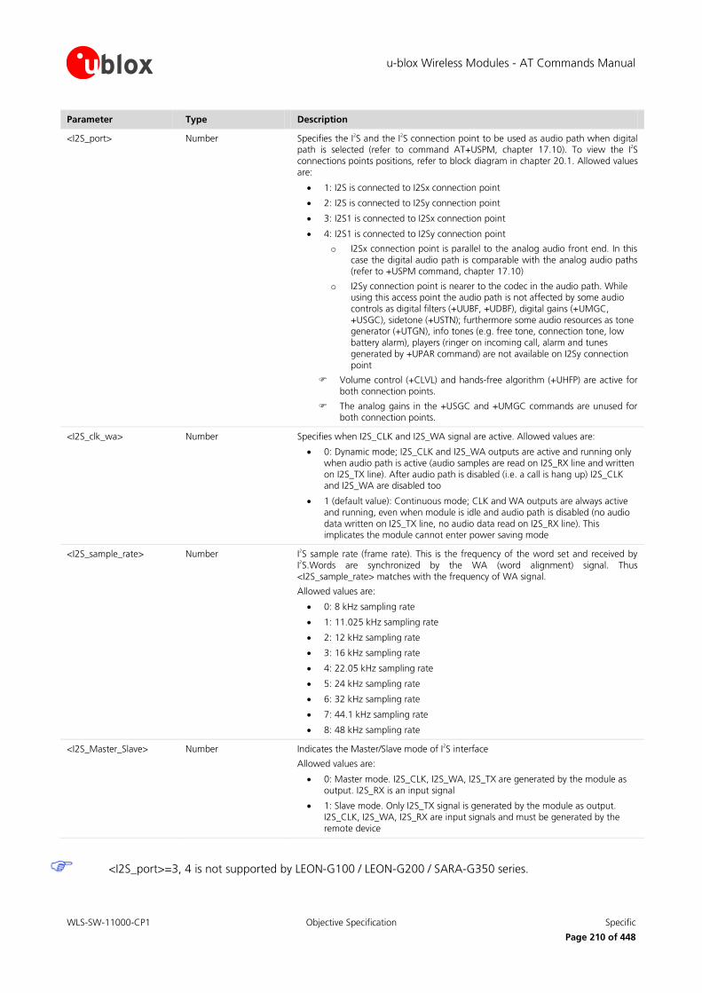
u-blox Wireless Modules - AT Commands Manual
WLS-SW-11000-CP1 Objective Specification Specific
Page 210 of 448
Parameter Type Description
<I2S_port> Number Specifies the I2S and the I
2S connection point to be used as audio path when digital
path is selected (refer to command AT+USPM, chapter 17.10). To view the I2S
connections points positions, refer to block diagram in chapter 20.1. Allowed values are:
1: I2S is connected to I2Sx connection point
2: I2S is connected to I2Sy connection point
3: I2S1 is connected to I2Sx connection point
4: I2S1 is connected to I2Sy connection point
o I2Sx connection point is parallel to the analog audio front end. In this case the digital audio path is comparable with the analog audio paths (refer to +USPM command, chapter 17.10)
o I2Sy connection point is nearer to the codec in the audio path. While using this access point the audio path is not affected by some audio controls as digital filters (+UUBF, +UDBF), digital gains (+UMGC, +USGC), sidetone (+USTN); furthermore some audio resources as tone generator (+UTGN), info tones (e.g. free tone, connection tone, low battery alarm), players (ringer on incoming call, alarm and tunes generated by +UPAR command) are not available on I2Sy connection point
Volume control (+CLVL) and hands-free algorithm (+UHFP) are active for both connection points.
The analog gains in the +USGC and +UMGC commands are unused for both connection points.
<I2S_clk_wa> Number Specifies when I2S_CLK and I2S_WA signal are active. Allowed values are:
0: Dynamic mode; I2S_CLK and I2S_WA outputs are active and running only when audio path is active (audio samples are read on I2S_RX line and written on I2S_TX line). After audio path is disabled (i.e. a call is hang up) I2S_CLK and I2S_WA are disabled too
1 (default value): Continuous mode; CLK and WA outputs are always active and running, even when module is idle and audio path is disabled (no audio data written on I2S_TX line, no audio data read on I2S_RX line). This implicates the module cannot enter power saving mode
<I2S_sample_rate> Number I2S sample rate (frame rate). This is the frequency of the word set and received by
I2S.Words are synchronized by the WA (word alignment) signal. Thus
<I2S_sample_rate> matches with the frequency of WA signal.
Allowed values are:
0: 8 kHz sampling rate
1: 11.025 kHz sampling rate
2: 12 kHz sampling rate
3: 16 kHz sampling rate
4: 22.05 kHz sampling rate
5: 24 kHz sampling rate
6: 32 kHz sampling rate
7: 44.1 kHz sampling rate
8: 48 kHz sampling rate
<I2S_Master_Slave> Number Indicates the Master/Slave mode of I2S interface
Allowed values are:
0: Master mode. I2S_CLK, I2S_WA, I2S_TX are generated by the module as output. I2S_RX is an input signal
1: Slave mode. Only I2S_TX signal is generated by the module as output. I2S_CLK, I2S_WA, I2S_RX are input signals and must be generated by the remote device
<I2S_port>=3, 4 is not supported by LEON-G100 / LEON-G200 / SARA-G350 series.

u-blox Wireless Modules - AT Commands Manual
WLS-SW-11000-CP1 Objective Specification Specific
Page 211 of 448
<I2S_port>=2, 3, 4 is not supported by LISA-U1 series.
<I2S_port>=2, 4 is not supported by LISA-U2 series.
If an incorrect number of parameters is provided or the parameter value is out of range the error
message “+CME ERROR: operation not supported” will be provided is +CMEE is set to 2:
o LEON-G100 / LEON-G200 / SARA-G350 and LISA-U1 series: +UI2S command returns ERROR when audio path is in digital mode (+USPM: 2,4,0,0). This is because the I
2S settings cannot be
changed when the audio path is configured to use this interface. It is necessary to disable the
audio path with AT+USPM=0,0,0,0, configure the I2S interface, and then re-select the digital
path with AT+USPM=2,4,0,0
o LISA-U2 series: +UI2S command returns ERROR when the <I2S_port> specified is used by the
current audio path (<I2S_port>=3; +USPM: 8,7,0,0). The I2S settings cannot be changed when
the audio path is configured to use this interface. It is necessary to change the audio path by
+USPM to a configuration not using the <I2S_port>, configure the <I2S_port> by +UI2S, and
then re-select the +USPM mode using the <I2S_port> specified.
o +UI2S command returns ERROR if I2S pins are already allocated by another resource
o +UI2S settings are saved in NVM after power off if changed
Allowed combination of <I2S_mode> and <I2S_port> are described in Table 4 and Table 5.
PCM modes Normal I2S modes
I2Sx connection of I2S (0-1) Not supported
I2Sy connection of I2S Not supported (2-13)
I2Sx connection of I2S1 Not supported Not supported
I2Sy connection of I2S1 Not supported Not supported
Table 4: LEON-G100 / LEON-G200 / SARA-G350 series I2S modes
PCM modes Normal I2S modes
I2Sx connection of I2S (0-1) (2-13)
I2Sy connection of I2S Not supported Not supported
I2Sx connection of I2S1 Not supported Not supported
I2Sy connection of I2S1 Not supported Not supported
Table 5: LISA-U1 series I2S modes
<I2S_port> PCM modes Normal I2S modes
I2Sx connection of I2S (0-1) (2-13)
I2Sy connection of I2S Not supported Not supported
I2Sx connection of I2S1 (0-1) (2-13)
I2Sy connection of I2S1 Not supported Not supported
Table 6: LISA-U2 series I2S modes

u-blox Wireless Modules - AT Commands Manual
WLS-SW-11000-CP1 Objective Specification Specific
Page 212 of 448
17.9.3 PCM modes (short synchronization signal)
Mode CLK EDGE for TX CLK EDGE for RX WA pulse length CLK Freq. WA Freq.
0 RISING FALLING 2 clks 18*<I2S_sample_rate> <I2S_sample_rate>
1 RISING FALLING 1 clk 17*<I2S_sample_rate> <I2S_sample_rate>
17.9.4 PCM modes timing diagrams
WA (PCM mode 0): pulse is 2 bits wide; 18 clocks / WA cycle
TXD (PCM mode 0): After synchronization bit (0), MSB is transmitted twice and Word is aligned on WA falling edge
WA (PCM mode 1): pulse is 1 bits wide; 17 clocks / WA cycle
TXD (PCM mode 1): After synchronization bit (0), word is aligned on WA falling edge
A single Transmitted word is marked in grey. MSB is marked darker.
Since RXD bits are read on the falling edge of CLK signal, the RXD word slot starts half bit delayed respect TXD word slot.
Relation between WA and CLK edge for PCM mode is:
WA
CLK

u-blox Wireless Modules - AT Commands Manual
WLS-SW-11000-CP1 Objective Specification Specific
Page 213 of 448
17.9.5 Normal I2S modes (long synchronization signal)
Mode CLK edge for TX CLK edge for RX MSB Delay TX channel RX channel CLK Frequency WA Frequency
2 FALLING RISING 1 bit WA LOW WA LOW 32*<I2S_sample_rate> <I2S_sample_rate>
3 RISING FALLING 1 bit WA LOW WA LOW 32*<I2S_sample_rate> <I2S_sample_rate>
4 FALLING RISING 0 bit WA LOW WA LOW 32*<I2S_sample_rate> <I2S_sample_rate>
5 RISING FALLING 0 bit WA LOW WA LOW 32*<I2S_sample_rate> <I2S_sample_rate>
6 FALLING RISING 1 bit WA HIGH WA HIGH 32*<I2S_sample_rate> <I2S_sample_rate>
7 RISING FALLING 1 bit WA HIGH WA HIGH 32*<I2S_sample_rate> <I2S_sample_rate>
8 FALLING RISING 0 bit WA HIGH WA HIGH 32*<I2S_sample_rate> <I2S_sample_rate>
9 RISING FALLING 0 bit WA HIGH WA HIGH 32*<I2S_sample_rate> <I2S_sample_rate>
10 FALLING RISING 1 bit WA HIGH &
LOW WA HIGH 32*<I2S_sample_rate> <I2S_sample_rate>
11 RISING FALLING 1 bit WA HIGH &
LOW WA HIGH 32*<I2S_sample_rate> <I2S_sample_rate>
12 FALLING RISING 0 bit WA HIGH &
LOW WA HIGH 32*<I2S_sample_rate> <I2S_sample_rate>
13 RISING FALLING 0 bit WA HIGH &
LOW WA HIGH 32*<I2S_sample_rate> <I2S_sample_rate>

u-blox Wireless Modules - AT Commands Manual
WLS-SW-11000-CP1 Objective Specification Specific
Page 214 of 448
17.9.6 Normal I2S modes timing diagrams
WA (all normal modes)
TXD timeslot (Normal modes 2-3): 1 bit delay; channel on WA low
TXD timeslot (Normal modes 4-5): 0 bit delay; channel on WA low
TXD (Normal modes 6-7):1 bit delay; channel on WA high
TXD (Normal modes 8-9): 0 bit delay; channel on WA high
TXD (Normal modes 10-11):1 bit delay; channel on WA high and low
TXD (Normal modes 12-13): 0 bit delay; channel on WA high and low
A single Transmitted word is marked in grey. MSB is marked darker.
Since RXD bits are read on the opposite edge of CLK signal respect TXD bits, the RXD word slot starts half bit
delayed respect TXD word slot.

u-blox Wireless Modules - AT Commands Manual
WLS-SW-11000-CP1 Objective Specification Specific
Page 215 of 448
Relation between WA and CLK edge for Normal I2S depends on mode:
WA WA
CLK (modes 3,5,7,9,11,13) CLK (modes 2,4,6,8,10)
17.10 Audio Path mode setting (Set Path Mode) +USPM
17.10.1 Description
Sets the audio Path Mode. The path mode is the way of enabling the different audio paths (audio input and
output) of the module for different usecases.
Not supported by LISA-U200-00S version.
Type Syntax Response Example
Set AT+USPM=<main_uplink>,<main_downlink>,<alert_sound>,<headset_indication>[,<vmic_ctrl>]
OK AT+USPM=1,1,0,0
OK
Read AT+USPM? +USPM: <main_uplink>,<main_downlink>,<alert_sound>,<headset_indication>,<vmic_ctrl>
OK
+USPM: 0,0,0,0,2
OK
Test AT+USPM=? +USPM: (list of supported <main_uplink>s),(list of supported <main_downlink>s),(list of supported <alert_sound>s),(list of supported <headset_indication>s) , (list of supported <vmic_ctrl>s)
OK
+USPM: (0-2),(0,1,3,4),(0-1),(0-1),(0-2)
OK
17.10.2 Defined values
Parameter Type Description
<main_uplink> Number Specifies the audio input path used for speech:
0 (default value): Handset microphone (LEON-G100 / LEON-G200 pins: MIC_BIAS1, MIC_GND1; SARA-G350 series pins: MIC_P, MIC_N, MIC_BIAS, MIC_GND; LISA-U1 series pins MIC_P, MIC_N)
1 (default value for SARA-G350 series): Headset microphone (LEON-G100 / LEON-G200 pins: MIC_BIAS2, MIC_GND2; SARA-G350 series pins: MIC_P, MIC_N, MIC_BIAS, MIC_GND; LISA-U1 series pins MIC_P, MIC_N)
2: I2S input line (pin I2S_RXD)
4: Hands-free microphone (LISA-U1 series pins: MIC_P, MIC_N)
For LISA-U2 series, the meaning and range of this parameter is:
0: Uplink path 0 via I2S

u-blox Wireless Modules - AT Commands Manual
WLS-SW-11000-CP1 Objective Specification Specific
Page 216 of 448
Parameter Type Description
1: Uplink path 1 via I2S
2: Uplink path 2 via I2S
3: Uplink path 3 via I2S
4: Uplink path 4 via I2S
5: Uplink path 5 via I2S1
6: Uplink path 6 via I2S1
7: Uplink path 7 via I2S1
8: Uplink path 8 via I2S1
9: Uplink path 9 via I2S1
<main_downlink> Number Specifies the audio output path used for speech:
0 (default value): Normal earpiece (LEON-G100 / LEON-G200 pins: HS_P / GND; LISA-U1 series / SARA-G350 pins: SPK_N / SPK_P)
1 (default value for SARA-G350 series): Mono headset (LEON-G100 / LEON-G200 pins: HS_P, GND; LISA-U1 / SARA-G350 series pins: SPK_N, SPK_P)
2: Stereo headset
3: Loudspeaker (LEON-G100 / LEON-G200 pins: SPK_P, SPK_N; LISA-U1 / SARA-G350 series pins: SPK_N, SPK_P)
4: I2S output line (pin I2S_TXD).
For LISA-U2 series, the meaning and range of this parameter is:
0: Downlink path 0 via I2S
1: Downlink path 1 via I2S
2: Downlink path 2 via I2S
3: Downlink path 3 via I2S
4: Downlink path 4 via I2S
5: Downlink path 5 via I2S1
6: Downlink path 6 via I2S1
7: Downlink path 7 via I2S1
8: Downlink path 8 via I2S1
9: Downlink path 9 via I2S1
<alert_sound> Number Specifies if the alert sounds in idle mode are played on the main downlink path (same downlink path as speech; see <main_downlink> parameter) or on the loudspeaker:
0 (default value for LISA-U1 series): Main downlink path
1 (default value for LEON-G100/ LEON-G200): Loudspeaker
<headset_indication> Number Specifies if the speech path is switched on headset or not when the headset is inserted:
0 (default value for LISA-U1 series): Headset indication not considered
1 (default value for LEON-G100 / LEON-G200): Headset indication considered
<vmic_ctrl> Number Specifies the control mode for microphones voltage supply (VMIC). Both LEON microphones bias pins (MIC_BIAS1, MIC_BIAS2) are supplied by VMIC.
0 (default value for LEON-G100/ LEON-G200): VMIC is switched on/off synchronously with the microphone amplifier; i.e. while module is idle or is using I
2S input line, microphone amplifiers and VMIC are switched off
1: VMIC is switched always on
2 (default value for LISA-U1 series): VMIC is switched always off
<error> String If an incorrect number of parameters is provided or the parameter values are out of range the error message “+CME ERROR: operation not supported” will be provided if +CMEE is set to 2
<main_uplink>=4 is not supported by LEON-G100 / LEON-G200 series.

u-blox Wireless Modules - AT Commands Manual
WLS-SW-11000-CP1 Objective Specification Specific
Page 217 of 448
<main_downlink>=2 is not supported by LEON-G100 / LEON-G200 / SARA-G350 or LISA-U1 series.
<alert_sound>=1 and <headset_indication>=1 are not supported by LISA-U1 series.
<vmic_ctrl>=0 and <vmic_ctrl>=1 are not supported by LISA-U1 series.
On LEON-G100 / LEON-G200 / SARA-G350 series the following combination of parameters
<main_uplink>, <main_downlink>, <alert_sound>, <headset_indication> are allowed:
o 0, 0, 0, 1: Handset microphone, Normal earpiece, Alert on main path, Headset indication considered
o 0, 0, 1, 1: Handset microphone, Normal earpiece, Alert on loudspeaker, Headset indication
considered
o 0, 0, 0, 0: Handset microphone, Normal earpiece, Alert on main path, Headset indication not
considered
o 0, 0, 1, 0: Handset microphone, Normal earpiece, Alert on loudspeaker, Headset indication not considered
o 0, 3, 0, 0: Handset microphone, Loudspeaker, Alert on main path, Headset indication not
considered
o 0, 3, 0, 1: Handset microphone, Loudspeaker, Alert on main path, Headset indication
considered
o 0, 1, 0, 0: Handset microphone, Mono headset, Alert on main path, Headset indication not considered
o 1, 1, 0, 0: Headset microphone, Mono headset, Alert on main path, Headset indication not
considered
o 1, 0, 0, 0: Headset microphone, Normal earpiece, Alert on main path, Headset indication not
considered
o 1, 0, 1, 0: Headset microphone, Normal earpiece, Alert on loudspeaker, Headset indication not considered
o 1, 3, 0, 0: Headset microphone, Loudspeaker, Alert on main path, Headset indication not
considered
o 2, 4, 0, 0: I2S input, I
2S output, Alert on main path, Headset indication not considered
On LISA-U1 series the following combination of parameters <main_uplink>, <main_downlink> are
allowed (<alert_sound>, <headset_indication> must always be set to 0):
Uplink\Downlink
0 -
Norm
al earp
iece
1 -
Mon
o h
eadse
t
2 -
Un
use
d
3 -
Loud
speaker
4 -
I2S o
utp
ut
0 - Handset Microphone x x
x
1 - Headset Microphone x x
x
2 - I2S input
x
3 - Unused
4 - Hands-free Microphone x x
x
Besides the routing via analog or digital interface, the uplink and uplink paths include a set of audio parameters (gains, digital filters, echo canceller parameters). Uplink paths can be edited by AT

u-blox Wireless Modules - AT Commands Manual
WLS-SW-11000-CP1 Objective Specification Specific
Page 218 of 448
commands Microphone Gain Control (+UMGC), Uplink Biquad Filters (+UUBF), Hands-Free Parameters (+UHFP), all using the uplink path index.
Downlink paths can be edited by AT commands Speaker Gain Control (+USGC), Downlink Biquad Filters
(+UDBF), Sidetone (+USTN), all using the downlink path index.
The command Set Pat Mode (+USPM) is used to choose the uplink and downlink path used.
Only one single uplink path and one single downlink path can be used. Parallel paths are not managed.
On LISA-U2 series the following combination of parameters <main_uplink>, <main_downlink> are allowed:
Uplink\Downlink
0 -
Up
link p
ath
0 v
ia I2S
1 -
Up
link p
ath
1 v
ia I2S
2 -
Up
link p
ath
2 v
ia I2S
3 -
Up
link p
ath
3 v
ia I2S
4 -
Up
link p
ath
4 v
ia I2S
5 -
Up
link p
ath
5 v
ia I2S1
6 -
Up
link p
ath
6 v
ia I2S1
7 -
Up
link p
ath
7 v
ia I2S1
8 -
Up
link p
ath
8 v
ia I2S1
9 -
Up
link p
ath
9 v
ia I2S1
0 - Uplink path 0 via I2S x x x x x
1 - Uplink path 1 via I2S x x x x x
2 - Uplink path 2 via I2S x x x x x
3 - Uplink path 3 via I2S x x x x x
4 - Uplink path 4 via I2S x x x x x
5 - Uplink path 5 via I2S1
x x x x x
6 - Uplink path 6 via I2S1
x x x x x
7 - Uplink path 7 via I2S1
x x x x x
8 - Uplink path 8 via I2S1
x x x x x
9 - Uplink path 9 via I2S1
x x x x x
17.11 Play audio resource (Play Audio Resource) +UPAR
17.11.1 Description
Starts the playback of the pre-defined tone of the selected audio resource.
Not supported by LISA-U200-00S version.
<audio_resource>=1 (MIDI player) is not supported by LISA-U1 / LISA-U2 series.
<audio_resource>=2 (audio loop for test purposes) is not supported by LEON-G100 / LEON-G200 /
SARA-G350 or LISA-U1 series.
Type Syntax Response Example
Set AT+UPAR=<audio_resource>,<tone_id>,<nof_repeats>
OK AT+UPAR=0,1,0
OK

u-blox Wireless Modules - AT Commands Manual
WLS-SW-11000-CP1 Objective Specification Specific
Page 219 of 448
Type Syntax Response Example
Test AT+UPAR=? +UPAR: (list of supported <audio_resource>s),(list of supported <tone_id>s),(list of supported <nof_repeats>s)
OK
+UPAR: (0-1),(0-66),(0-255)
OK
17.11.2 Defined values
Parameter Type Description
<audio_resource> Number Specifies the audio resource
0: tone generator
1: MIDI player
2: audio loop for test purposes. Use this command to generate an audio loop between uplink and downlink current path (+USPM) when not in a call. Use the sidetone command (+USTN) for loop amount configuration. For uplink to downlink loop on call use sidetone (+USTN) command only
<tone_id> Number Specifies the pre-defined tone id to be played; the supported values depend by <audio_resource> values according to the tables reported below
<nof_repeats> Number Specifies the number of repeats
0: infinite loop
n: n repeats
<error> Number If an incorrect number of parameters is provided or the parameter values are out of range the error message “+CME ERROR: operation not supported” will be provided if +CMEE is set to 2
Possible values for tone generator are:
id tone id tone id tone
0 DTMF 0 23 service tone 6 46 melody 0
1 DTMF 1 24 service tone 7 47 melody 1
2 DTMF 2 25 service tone 8 48 melody 2
3 DTMF 3 26 service tone 9 49 melody 3
4 DTMF 4 27 service tone 10 50 melody 4
5 DTMF 5 28 service tone 11 51 melody 5
6 DTMF 6 29 service tone 12 52 melody 6
7 DTMF 7 30 service tone 13 53 melody 7
8 DTMF 8 31 service tone 14 54 melody 8
9 DTMF 9 32 service tone 15 55 melody 9
10 DTMF hash 33 service tone 16 56 melody 10
11 DTMF asterix 34 service tone 17 57 melody 11
12 key tone 1 35 service tone 18 58 melody 12
13 key tone 2 36 service tone 19 59 melody 13
14 key tone 3 37 service tone 20 60 melody 14
15 key tone 4 38 service tone 21 61 melody 15
16 key tone 5 39 service tone 22 62 melody 16
17 service tone 0 40 service tone 23 63 melody 17
18 service tone 1 41 service tone 24 64 melody 18
19 service tone 2 42 service tone 25 65 service tone 29
20 service tone 3 43 service tone 26 66 service tone 30
21 service tone 4 44 service tone 27

u-blox Wireless Modules - AT Commands Manual
WLS-SW-11000-CP1 Objective Specification Specific
Page 220 of 448
id tone id tone id tone
22 service tone 5 45 service tone 28
Possible values for <audio_resource>=1 (MIDI player) are:
id ringing tone id ringing tone
0 ring 5 ramp spmidi
1 baroque 6 mozart imel
2 caribic 7 whenever
3 jamesbond 8 imperialmarch
4 moonstar
MIDI Melodies are the same selectable as ringer by +URNG command.
17.12 Stop audio resource (Stop Audio Resource) +USAR
17.12.1 Description
This command stops the playback of the selected audio resource.
Not supported by LISA-U200-00S version.
Type Syntax Response Example
Set AT+USAR=<audio_resource> OK AT+USAR=0
OK
Test AT+USAR=? +USAR: (list of supported <audio_resource>s)
OK
+USAR: (0-1)
OK
17.12.2 Defined values
Parameter Type Description
<audio_resource> Number Specifies the audio resource
0: DSP tone generator
1: MIDI player
<error> Number If an incorrect number of parameters is provided or the parameter values are out of range the error message “+CME ERROR: operation not supported” will be provided if +CMEE is set to 2
17.13 Play audio file +UPLAYFILE
17.13.1 Description
Play the specified audio file stored into the file system. For more details about file system description refer to
chapter 18 “File System AT commands”.
Not supported by LISA-U200-00S version.
When finish playing the file, a status indication is sent to DTE in a form of +UPLAYFILE.

u-blox Wireless Modules - AT Commands Manual
WLS-SW-11000-CP1 Objective Specification Specific
Page 221 of 448
The command provides an error message if +CRSL is set to 0.
LEON-G100/G200 series modules support AMR audio file. The storage format of AMR encoded audio
content must be compliant to RFC3267 [54].
LISA-U1 series modules support PCM audio file. The storage format of PCM audio files must be: 8 kHz
sample rate, signed 16 bits, little endian, mono.
With LISA-U1x0-01S, the player is stopped and a URC (+UPLAYFILE STOPPED) is provided in the
following cases:
o Call dialup or hangup during file playing
o Call handover with a narrow band/wide band speech change during file playing
The URC (+UPLAYFILE STOPPED) is not available on LEON-G100 / LEON-G200 / SARA-G350 series and
LISA-U1x0-00S versions.
Type Syntax Response Example
Set AT+UPLAYFILE=<filename> OK AT+UPLAYFILE="file1.amr"
OK
Read AT+UPLAYFILE? +UPLAYFILE: <playstatus>
OK
+UPLAYFILE: 0
OK
URC +UPLAYFILE STOPPED
17.13.2 Defined values
Parameter Type Description
<filename> String Specifies the audio resource file name to be played
<playstatus> Number Play status
0: no file is playing
1: the file is playing
<error> Number If an incorrect number of parameters is provided or the parameter values are out of range the error message “+CME ERROR: operation not supported” will be provided if +CMEE is set to 2
If <filename> file is not present in the file system the error message “+CME ERROR: FILE NOT FOUND” will be provided if +CMEE is set to 2
17.14 Stop AMR audio file +USTOPFILE
17.14.1 Description
Stop the AMR audio file reproduction.
A URC is provided after the file is correctly stopped by AT+USTOPFILE command.
Not supported by LISA-U200-00S version.
With LISA-U1x0-01S, the player is stopped and a URC (+UPLAYFILE STOPPED) is provided in the
following cases:
o Call dialup or hangup during file playing
o Call handover with a narrow band/wide band speech change during file playing
The URC is not available on LEON-G100 / LEON-G200 / SARA-G350 series and LISA-U1x0-00S versions.

u-blox Wireless Modules - AT Commands Manual
WLS-SW-11000-CP1 Objective Specification Specific
Page 222 of 448
Type Syntax Response Example
Action AT+USTOPFILE OK AT+USTOPFILE
OK
URC +UPLAYFILE STOPPED
17.15 Jamming Detection +UCD
17.15.1 Description
The feature consists in detecting, at radio resource level, an anomalous source of interference and signalling it to
the client. The jamming condition occurs when simultaneously:
The MT has lost synchronization with the serving cell and cannot select any other suitable cell
The band scan reveals at least n carriers with power level equal or higher than threshold
On all such carriers, no synchronization is possible
The minimum number of disturbing carriers and the power level threshold can be configured by the client
through this command.
The jamming condition is cleared when any of the above mentioned statements does not hold.
The command configures how jamming is reported. If activated, an unsolicited indication is issued when the jamming condition is entered or released. In particular, the set command configures the URC +UCD: <active>.
<mode>=2 is not supported by LEON-G100-05S / LEON-G200-05S and previous versions.
<mode>=3 and <mode>=4 are not supported by LEON-G100 / LEON-G200 / SARA-G350 series (thus
<min_number_of_3G_carriers>, <rssi_threshold> are also not present).
<mode>=2 returns the <active> value, if and only if the URC has been previously enabled. Otherwise the “Operation not allowed” error (see Appendix A.6 for error codes) is generated.
<mode>=2 doesn’t change the stored <mode> value.
When using <mode>=2 in the set command, the remaining parameters are not mandatory.
On LISA-U1 / LISA-U2 series the <active> value is not provided in the response to the set command.
On LISA-U1 / LISA-U2 series the jamming detection can be enabled / disabled only on one AT interface at a time. Once disabled on that AT interface, it can be enabled on a different one.
Type Syntax Response Example
Set AT+UCD=<mode>[,<min_number_of_2G_carriers>,<rxlev_threshold>,<min_number_of_3G_carriers>,<rssi_threshold>]
[+UCD: <active>]
OK
AT+UCD=3,,,10,20
OK
AT+UCD=2
+UCD: 1
OK

u-blox Wireless Modules - AT Commands Manual
WLS-SW-11000-CP1 Objective Specification Specific
Page 223 of 448
Type Syntax Response Example
Read AT+UCD? if <mode>=1
+UCD: <mode>,<min_number_of_2G_carriers>,<rxlev_threshold>
OK
if <mode>=3
+UCD: <mode>,,,<min_number_of_3G_carriers>,<rssi_threshold>
OK
if <mode>=4
+UCD: <mode>,<min_number_of_2G_carriers>,<rxlev_threshold>,<min_number_of_3G_carriers>,<rssi_threshold>
OK
+UCD: 1,10,20
OK
+UCD: 3,11,25
OK
+UCD: 4,10,20,11,25
OK
Test AT+UCD=? +UCD: (range of supported <mode>),(range of supported <min_number_of_2G_carriers>),(range of supported <rxlev_threshold>),(range of supported <min_number_of_3G_carriers>),(<range of supported <rssi_threshold>)
OK
+UCD: (0-4),(1-172),(3-63),(1-136),(0-76)
OK
URC +UCD: <active> +UCD: 3
17.15.2 Defined values
Parameter Type Description
<mode> Number 0: disable congestion URC
1: enable 2G congestion URC +UCD: <active>
2: return the <active> value
3: enable 3G congestion URC +UCD: <active>
4: enable 2G and 3G congestion URC +UCD: <active>
<min_number_of_2G_carriers> Number Number of minimum disturbing carriers
Mandatory parameter if <mode>=1 or <mode>=4; if <mode>=3 the parameter has to be omitted
Range between 1 and 255 in LEON-G100 / LEON-G200 / SARA-G350 series
Range between 1 and 172 in LISA-U1 / LISA-U2 series
<rxlev_threshold> Number Power level threshold for 2G carriers; refer to [28]
Mandatory parameter if <mode>=1 or <mode>=4; if <mode>=3 the parameter has to be omitted
Range between 3 to 63
<min_number_of_3G_carriers> Number Number of minimum disturbing carriers
Mandatory parameter if <mode>=3 or <mode>=4; if <mode>=0 or <mode>=1 the parameter has to be omitted
Range between 1 and 136
<rssi_threshold> Number Power level threshold for 3G carriers
Mandatory parameter if <mode>=3 or <mode>=4; if <mode>=0 or <mode>=1 the parameter has to be omitted
Range between 0 and 76
<active> Number 0: the 2G congestion condition is cleared

u-blox Wireless Modules - AT Commands Manual
WLS-SW-11000-CP1 Objective Specification Specific
Page 224 of 448
Parameter Type Description
1: the MT is entered the 2G congestion condition
2: the 3G congestion condition is cleared
3: the MT is entered the 3G congestion condition
17.16 Select Band +UBANDSEL
17.16.1 Description
Allows switching from automatic band selection to selection of one or more (up to four) bands from the
following:
2G network
o 850 MHz
o 900 MHz
o 1800 MHz
o 1900 MHz
3G network
o 800 MHz (Band VI)
o 850 MHz (Band V)
o 900 MHz (Band VIII)
o 1500 MHz (Band XI)
o 1700 MHz (Band IV)
o 1800 MHz (Band III)
o 1900 MHz (Band II)
o 2100 MHz (Band I)
o 2600 MHz (Band VII)
On LISA-U1 and LISA-U2 series the list of supported bands presents exclusively GSM or UMTS bands
depending on which RAT the MT is currently registered. If it is not registered, the bands presented depend on +URAT command:
o If in single mode, depends on <AcT>
o If in dual mode, depends on <PreferredAct> (thus the command forces a single mode behavior)
The MT will camp on a cell, if suitable, belonging to one of the selected band; the OK response is
regardless of the result of the camping on the new cell.
To have effective the setting, the module must be deregistered and registered again (using the
commands +COPS=2, +COPS=0).
The configuration is saved in NVM for future registration attempts.
Type Syntax Response Example
Set AT+UBANDSEL=<band_1>[,<band_2>[,…]]
OK AT+UBANDSEL=900
OK
Read AT+UBANDSEL? +UBANDSEL: <band_1>[,<band_2>[,…]]
OK
+UBANDSEL: 850,900,1800,1900
OK
Test AT+UBANDSEL=? +UBANDSEL: (list of supported <band_x>)
OK
+UBANDSEL: (0,850,900,1800,1900)
OK

u-blox Wireless Modules - AT Commands Manual
WLS-SW-11000-CP1 Objective Specification Specific
Page 225 of 448
17.16.2 Defined values
Parameter Type Description
<band_x> Number 0: restore the factory-programmed configuration of the module
800: selection of 800 MHz band
850: selection of 850 MHz band
900: selection of 900 MHz band
1500: selection of 1500 MHz band
1700: selection of 1700 MHz band
1800: selection of 1800 MHz band
1900: selection of 1900 MHz band
2100: selection of 2100 MHz band
2600: selection of 2600 MHz band
17.17 Set reporting call status +UCALLSTAT
17.17.1 Description
Allows to enable / disable the reporting voice call status on DTE using the URC +UCALLSTAT. This URC is
generated each time a call status change occurs. When multiple calls change status at the same time (e.g. when all multiparty calls are terminated) an URC +UCALLSTAT is generated for each of them.
Type Syntax Response Example
Set AT+UCALLSTAT=<enable> OK AT+UCALLSTAT=1
OK
Read AT+UCALLSTAT? +UCALLSTAT: <enable>
OK
+UCALLSTAT: 1
OK
Test AT+UCALLSTAT=? +UCALLSTAT: (list of supported <enable>’s)
OK
+UCALLSTAT: (0-1)
OK
URC +UCALLSTAT: <call_id>,<stat> +UCALLSTAT: 1,2
17.17.2 Defined values
Parameter Type Description
<enable> Number 0: reporting disabled
1: reporting enabled
<call_id> Number Indicates the call identification (refer to 3GPP TS 22.030 [15])
<stat> Number Indicates the voice call status
0: active
1: hold
2: dialling (Mobile Originated call)
3: alerting (Mobile Originated call; ringing for the remote party)
4: ringing (Mobile Terminated call)
5: waiting (Mobile Terminated call)
6: disconnected
7: connected (indicates the completion of a call setup first time for MT and

u-blox Wireless Modules - AT Commands Manual
WLS-SW-11000-CP1 Objective Specification Specific
Page 226 of 448
Parameter Type Description
MO calls – this is reported in addition to state active)
17.18 Display operator name +UDOPN
17.18.1 Description
The command displays the name of the network of the requested <type>. In case the requested information is not available (e.g. no SIM-files EF-OPL and EF-PNN), the command displays the network name which is most
similar to the requested <type>. In case the requested name is the Service Provider Name (<type>= 7), a null
string is displayed if not available.
In case EONS names are not available, NITZ names are displayed, if any. In case no NITZ name is available, CPHS
names are used. In case no CPHS name is available, ROM PLMN names are displayed.
In case no ROM PLN name matches to the current network, its numeric format (i.e. <type> 0) is returned.
Type Syntax Response Example
Set AT+UDOPN=<type> +UDOPN: <type>[,<name>[,<display_condition>]]
OK
AT+UDOPN=4
+UDOPN: 4,"Main Network"
OK
AT+UDOPN=7
+UDOPN: 7,"SERVICE-PROVIDER",1
OK
AT+UDOPN=7
+UDOPN: 7,""
OK
Test AT+UDOPN=? +UDOPN: (list of supported <type>s)
OK
+UDOPN: (0-9)
OK
17.18.2 Defined values
Parameter Type Description
<type> Number 0: numeric format of network MCC/MNC (three BCD digit country code and two/three BCD digit network
code)
1: Short Name in ROM
2: Long Name in ROM
3: Short Network Operator Name (CPHS)
4: Long Network Operator Name (CPHS)
5: Short NITZ Name
6: Full NITZ Name
7: Service Provider Name
8: EONS short operator name
9: EONS long operator name
11: Short Network Operator Name
12: Long Network Operator Name
<display_condition> Number Display condition as stored on SIM for the service provider name in respect to the registered PLMN (see GSM TS 11.11 [18] for more details).

u-blox Wireless Modules - AT Commands Manual
WLS-SW-11000-CP1 Objective Specification Specific
Page 227 of 448
Parameter Type Description
<name> String "network name": for <type> = 1, 2, 3, 4, 5 or 6
"additional Unicode network name": for <type> = 1 or 2
"service provider name": followed by <display_condition> for <type> 7
"MCC:MNC": for <type> = 0
EONS means Enhanced Operator Name from SIM-files EF-OPL and EF-PNN.
The coding of <name> is according to the +CSCS setting.
<type>=11 and <type>=12 are not supported by LEON-G100 / LEON-G200 / SARA-G350 series.
17.19 Device configuration +UDCONF
17.19.1 Description
Accesses several configurations and settings:
Changes the advanced settings for data transmission (PPP/LCP silent mode, HEX mode, UDP direct link
packet size and sending timer)
Steering of Roaming configuration
Speech codec configuration
Local DTMF tone generation
Enable/disable connection type groups
MSPR profile handling (see paragraph 17.19.1.1 below)
SIM hot insertion detection
Type Syntax Response Example
Set Generic syntax:
AT+UDCONF=<udconf_cmd_id>,…
OK AT+UDCONF=0,0
OK
PPP-LCP silent mode:
AT+UDCONF=0,<ppp_lcp_silent_mode>
OK AT+UDCONF=0,0
OK
Enable/Disable HEX mode for +USOWR, +USOST, +USORD and +USORF
commands:
AT+UDCONF=1,<hex_mode_disable>
OK AT+UDCONF=1,0
OK
UDP Direct Link: set packet size:
AT+UDCONF=2,<socket_id>[,<packet_size>]
OK AT+UDCONF=2,1,1024
OK
UDP Direct Link: set sending timer:
AT+UDCONF=3,<socket_id>,<sending_timer_timeout>
OK AT+UDCONF=2,1,1000
OK
ICMP Echo reply
AT+UDCONF=4,<icmp_echo_reply>
OK AT+UDCONF=4,1
OK
Steering of Roaming enable/disable:
AT+UDCONF=20,<SoR_enable>
OK AT+UDCONF=20,1
OK

u-blox Wireless Modules - AT Commands Manual
WLS-SW-11000-CP1 Objective Specification Specific
Page 228 of 448
Type Syntax Response Example
Speech codec configuration:
AT+UDCONF=30,[<codec_bitmap>]
OK AT+UDCONF=30,31
OK
Local DTMF tone generation:
AT+UDCONF=31,<local_tone_generation>
OK AT+UDCONF=31,1
OK
Connection type group enable/disable:
AT+UDCONF=32,<conn_type_groups_bitmap>
OK AT+UDCONF=32,1
OK
User defined power reduction:
AT+UDCONF=40,<GPRS_profile>[,<EDGE_profile>]
OK AT+UDCONF=40,2,3
OK
SIM hot insertion detection:
AT+UDCONF=50,<sim_insertion_detect>
OK AT+UDCONF=50,1
OK
Get Generic syntax:
AT+UDCONF=<udconf_cmd_id>[,…]
+UDCONF: <udconf_cmd_id>,…
OK
AT+UDCONF=0
+UDCONF: 0,0
OK
PPP-LCP silent mode:
AT+UDCONF=0
AT+UDCONF: 0,<ppp_lcp_silent_mode>
OK
AT+UDCONF=0
AT+UDCONF: 0,0
OK
HEX mode for +USOWR, +USOST, +USORD and +USORF commands:
AT+UDCONF=1
+UDCONF: 1,<hex_mode_disable>
OK
AT+UDCONF=1
+UDCONF: 1,1
OK
UDP Direct Link: packet size:
AT+UDCONF=2,<socket_id>
+UDCONF: 2,<socket_id>,<packet_size>
OK
AT+UDCONF=2,1
AT+UDCONF: 2,1,1024
OK
UDP Direct Link: sending timer:
AT+UDCONF=3,<socket_id>
+UDCONF: 3,<socket_id>,<sending_timer_timeout>
OK
AT+UDCONF=3,1
AT+UDCONF: 3,1,1000
OK
ICMP Echo reply
AT+UDCONF=4,<icmp_echo_reply>
+UDCONF: 4,<icmp_echo_reply>
OK
AT+UDCONF=4
AT+UDCONF: 4,1
OK
Steering of Roaming:
AT+UDCONF=20
+UDCONF: 20,<SoR_enable>
OK
AT+UDCONF=20
AT+UDCONF: 20,1
OK
Speech codec configuration:
AT+UDCONF=30
+UDCONF: 30,<active_codec_bitmap>,<supported_codec_bitmap>
OK
AT+UDCONF=30
+UDCONF: 30,31,255
OK
Local DTMF tone generation:
AT+UDCONF=31
+UDCONF: 31,<local_tone_generation>
OK
AT+UDCONF=31
+UDCONF: 31,1
OK
Connection type groups enable/disable:
AT+UDCONF=32
+UDCONF: 32,<active_conn_type_groups_bitmap>,<configured_conn_type_groups_bitmap>
OK
AT+UDCONF=32
+UDCONF: 32,1,1
OK

u-blox Wireless Modules - AT Commands Manual
WLS-SW-11000-CP1 Objective Specification Specific
Page 229 of 448
Type Syntax Response Example
User defined power reduction:
AT+UDCONF=40
+UDCONF: 40,<GPRS_profile>,<EDGE_profile>
OK
AT+UDCONF=40
AT+UDCONF: 40,2,2
OK
SIM hot insertion detection:
AT+UDCONF=50
+UDCONF: 50,<sim_insertion_detect>
OK
AT+UDCONF=50
+UDCONF: 50,1
OK
Test Generic syntax:
AT+UDCONF=? +UDCONF: <udconf_cmd_id1>,(list of supported <param1> values for cmd 1),…
+UDCONF: <udconf_cmd_id2>,(list of supported <param1> values for cmd 2),…
…
+UDCONF: <udconf_cmd_idN>,(list of supported <param1> values for cmd N),…
OK
+UDCONF: 1,(0,1)
+UDCONF: 2,(0-6),(100-1472)
+UDCONF: 3,(0-6),(100-120000)
+UDCONF: 4,(0,1)
+UDCONF: 20,(0,1)
+UDCONF: 30,(0-4095)
+UDCONF: 31,(0,1)
+UDCONF: 32,(0-127)
+UDCONF: 40,(0-3),(0-3)
+UDCONF: 50,(0,1)
OK
HEX mode setting (<udconf_cmd_id>=1) is not supported by LEON-G100-05S / LEON-G200-05S and
previous versions or by LISA-U1x0-00S versions.
Packet size or sending timer for UDP Direct Link (<udconf_cmd_id>=2 or 3) is not supported by
LEON-G100 / LEON-G200 series or by LISA-U1x0-00S versions.
Steering of Roaming (<udconf_cmd_id>=20) is not supported by LEON-G100-06x /
LEON-G200-06x and previous versions, or by LISA-U1 and LISA-U200-00S versions.
Speech codec configuration (<udconf_cmd_id>=30) is not supported by LEON-G100 / LEON-G200
series, nor by LISA-U1 series and LISA-U200-00S version.
User-defined power reduction (<udconf_cmd_id>=40) is not supported by LEON-G100 / LEON-G200
series, or by LISA-U1 series and LISA-U200-00S version.
Local DTMF tone generation and connection type groups enable/disable are not supported by
LEON-G100 / LEON-G200 series or by LISA-U1 series or by LISA-U200-00S version.
The ICMP echo reply is not supported by LEON-G100 / LEON-G200 series, LISA-U1 series or by
LISA-U200-00S version.
SIM hot insertion detection is not supported by LEON-G100 / LEON-G200 series or by LISA-U1 series and
LISA-U200-00S version.
17.19.1.1 Notes for user-defined power reduction
Multi-slot transmission power can be reduced according to 3GPP specifications and set to a defined threshold by
means of the +UDCONF AT command.
In 3G mode (i.e. UMTS radio access), the maximum output power cannot be set by AT commands, but is automatically set by the module according to the UE Maximum Power Reduction for the nominal maximum
output power with HS-DPCCH and E-DCH defined by 3GPP specifications.
In 2G mode (i.e. GSM EDGE radio access), the maximum output power in GPRS or EDGE multi-slot configuration can be set by the +UDCONF AT command selecting the active multi-slot power reduction profile within the
available profiles defined in Table 7 according to 3GPP specifications.
The maximum output power in GPRS or EDGE multislot configuration depends on the active MSPR profile set by the +UDCONF AT command and the number of active Tx slots set by the network, as described in Table 7:

u-blox Wireless Modules - AT Commands Manual
WLS-SW-11000-CP1 Objective Specification Specific
Page 230 of 448
active Tx slots MSPR Profile 0 MSPR Profile 1 MSPR Profile 2 MSPR Profile 3
1 0 0 0 0
2 3 1 0 0
3 4,8 2,8 0,8 0
4 6 4 2 0
Table 7: Power reduction (dBm)
17.19.2 Defined values
Parameter Type Description
<udconf_cmd_id> Number Command identifier. AT+UDCONF can be used for several purposes (availability may change across different products):
0: PPP-LCP silent mode
1: Enable/Disable HEX mode for +USOWR, +USOST, +USORD and +USORF commands
2: UDP Direct Link: set packet size
3: UDP Direct Link: set sending timer
4: Enable/Disable ICMP ECHO REPLY (ping response). Not all the network operators allow ping traffic in their network.
20: enable/disable Steering of Roaming
30: speech codec configuration
31: local DMTF tone generation
32: connection type group enable/disable
40: user defined power reduction
50: enable / disable SIM hot insertion detection
Any other value is RFU and must not be used.
<ppp_lcp_silent_mode> Number Used to enable/disable PPP-LCP silent mode.
Valid values:
0: silent mode disabled, the module sends the first LCP frame
1 (default value): silent mode enabled, the module waits for the other end to start first
<hex_mode_disable> Number Used to enable/disable HEX mode for +USOWR, +USOST, +USORD and +USORF.
Valid values:
0 (default value): HEX mode disabled
1: HEX mode enabled
<socket_id> Number Socket identifier; used when changing the UDP Direct Link settings.
Valid range is 0-6
<packet_size> Number Packet size (in bytes) for UDP direct link; valid range is 100-1472; default value is 1024 bytes
<sending_timer_timeout> Number Sending timer (in milliseconds) for UDP direct link; valid range is 100-120000; default value is 1000 ms
<icmp_echo_reply> Number Enables or disables the ping response when a remote host performs a ping request to the module
0: ping response disabled (the module doesn’t reply to remote pings)
1: ping response enabled (default: the module replies to remote pings)
<SoR_enable> Number Steering of Roaming enable/disable:
0 (factory-programmed value): disable Steering of Roaming
1: enable Steering of Roaming
This setting can be changed only when the module is not registered to, and not searching for, a network (i.e. when +CREG’s <stat> is 0; see chapter 7.4.2). The

u-blox Wireless Modules - AT Commands Manual
WLS-SW-11000-CP1 Objective Specification Specific
Page 231 of 448
Parameter Type Description
new setting is saved in NVM and takes place at the next network registration / search.
<codec_bitmap> Number Bitmask representing the list of available speech codecs to be presented to the network during voice call setup.
Valid range is 0-31 (equivalent to bits 00000-11111) for LEON-G100 / LEON-G200 series and 0-4095 (equivalent to bits 000000000000-111111111111) for LISA-U1 / LISA-U2 series. The new setting is saved in NVM and is used immediately. As a factory-programmed setting, the Channel Codec bitmap is 31 on LEON-G100 / LEON-G200 series and 3135 on LISA-U2 series except LISA-U200-00S version.
See the following table for the meaning of each bit and codec availability:
Bit Codec LISA LEON
0 Full Rate Adaptive Multi-Rate • •
1 GSM Enhanced Full Rate (12.2 kb/s) • •
2 GSM Full Rate (13.0 kb/s) • •
3 Half Rate Adaptive Multi-Rate • •
4 GSM Half Rate (5.6 kb/s) • •
5 Full Rate Adaptive Multi-Rate WideBand • •
6 8PSK Half Rate Adaptive Multi-Rate •
7 8PSK Full Rate Adaptive Multi-Rate WideBand •
8 8PSK Half Rate Adaptive Multi-Rate WideBand •
9 UMTS Adaptive Multi-Rate •
10 UMTS Adaptive Multi-Rate 2 •
11 UMTS Adaptive Multi-Rate WideBand •
<active_codec_bitmap> Number The currently active codecs, in the format described for <codec_bitmap>
<supported_codec_bitmap> Number The list of currently supported codecs, in the format described for <codec_bitmap>
<local_tone_generation> Number Local DTMF tone generation enable / disable:
0: local DTMF tone generation is disabled (factory-programmed value)
1: local DTMF tone generation is enabled
This setting is volatile
<conn_type_groups_bitmap> Number Bitmask representing the list of “connection type groups” supported after reboot.
Valid range is 0-127 (equivalent to bits 0000000-1111111). The new setting is saved in NVM and is used only after reboot. The factory-programmed bitmask is 127 (all groups are supported).
See the following table for the meaning of each bit:
Bit Connection type group
0 UDI multimedia
1 UDI data
2 RDI
3 Audio 3.1 kHz
4 All sync transparent
5 All async transparent
6 All async non transparent
See the note below for the meaning of each group.
<active_conn_type_groups_bitmap> Number The currently active connection type groups, in the format described for
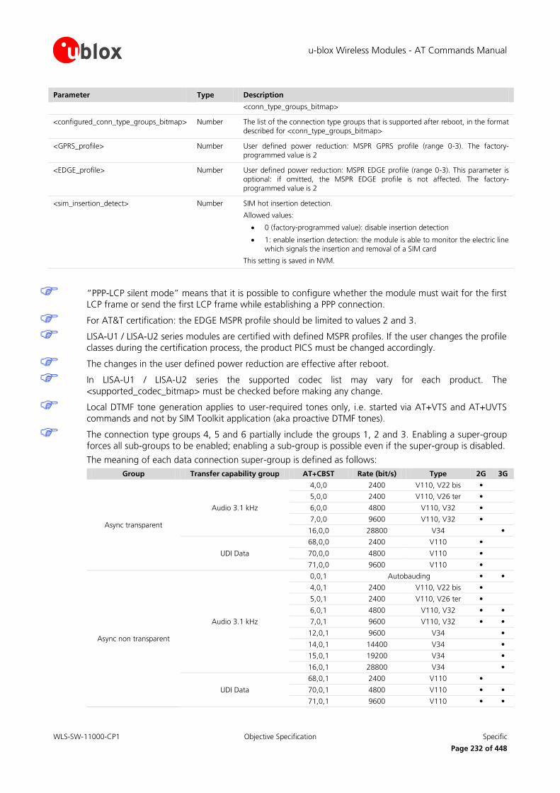
u-blox Wireless Modules - AT Commands Manual
WLS-SW-11000-CP1 Objective Specification Specific
Page 232 of 448
Parameter Type Description
<conn_type_groups_bitmap>
<configured_conn_type_groups_bitmap> Number The list of the connection type groups that is supported after reboot, in the format described for <conn_type_groups_bitmap>
<GPRS_profile> Number User defined power reduction: MSPR GPRS profile (range 0-3). The factory-programmed value is 2
<EDGE_profile> Number User defined power reduction: MSPR EDGE profile (range 0-3). This parameter is optional: if omitted, the MSPR EDGE profile is not affected. The factory-programmed value is 2
<sim_insertion_detect> Number SIM hot insertion detection.
Allowed values:
0 (factory-programmed value): disable insertion detection
1: enable insertion detection: the module is able to monitor the electric line which signals the insertion and removal of a SIM card
This setting is saved in NVM.
“PPP-LCP silent mode” means that it is possible to configure whether the module must wait for the first
LCP frame or send the first LCP frame while establishing a PPP connection.
For AT&T certification: the EDGE MSPR profile should be limited to values 2 and 3.
LISA-U1 / LISA-U2 series modules are certified with defined MSPR profiles. If the user changes the profile
classes during the certification process, the product PICS must be changed accordingly.
The changes in the user defined power reduction are effective after reboot.
In LISA-U1 / LISA-U2 series the supported codec list may vary for each product. The
<supported_codec_bitmap> must be checked before making any change.
Local DTMF tone generation applies to user-required tones only, i.e. started via AT+VTS and AT+UVTS
commands and not by SIM Toolkit application (aka proactive DTMF tones).
The connection type groups 4, 5 and 6 partially include the groups 1, 2 and 3. Enabling a super-group
forces all sub-groups to be enabled; enabling a sub-group is possible even if the super-group is disabled.
The meaning of each data connection super-group is defined as follows:
Group Transfer capability group AT+CBST Rate (bit/s) Type 2G 3G
Async transparent
Audio 3.1 kHz
4,0,0 2400 V110, V22 bis •
5,0,0 2400 V110, V26 ter •
6,0,0 4800 V110, V32 •
7,0,0 9600 V110, V32 •
16,0,0 28800 V34 •
UDI Data
68,0,0 2400 V110 •
70,0,0 4800 V110 •
71,0,0 9600 V110 •
Async non transparent
Audio 3.1 kHz
0,0,1 Autobauding • •
4,0,1 2400 V110, V22 bis •
5,0,1 2400 V110, V26 ter •
6,0,1 4800 V110, V32 • •
7,0,1 9600 V110, V32 • •
12,0,1 9600 V34 •
14,0,1 14400 V34 •
15,0,1 19200 V34 •
16,0,1 28800 V34 •
UDI Data
68,0,1 2400 V110 •
70,0,1 4800 V110 • •
71,0,1 9600 V110 • •

u-blox Wireless Modules - AT Commands Manual
WLS-SW-11000-CP1 Objective Specification Specific
Page 233 of 448
Group Transfer capability group AT+CBST Rate (bit/s) Type 2G 3G
75,0,1 14400 V110 •
79,0,1 19200 V110 •
80,0,1 28800 V110 •
81,0,1 38400 V110 •
RDI Data 83,0,1 56000 V110 •
UDI Data 84,0,1 64000 FTM •
Sync transparent
Audio 3.1 kHz 16,1,0 28800 V34 •
UDI Data 83,1,0 56000 V110 •
RDI Data 115,1,0 56000 •
UDI Data 116,1,0 64000 •
UDI Multimedia
130,1,0 64000 •
131,1,0 64000 •
133,1,0 64000 •
134,1,0 64000 •
Table 8: Data connection groups: meaning, availability and relationship with AT+CBST parameters
If a call class is disabled then:
o The outgoing calls are rejected when the ATD command is invoked (NO CARRIER is printed)
o The incoming calls are rejected by the stack and the user will receive no notification (e.g. no RING)
The changes in the user defined power reduction and SIM hot insertion detection are effective after
reboot.
17.20 Display EONS names +UEONS
17.20.1 Description
This command displays the list of available networks adding EONS names if available. The list of available
networks with details like long operator name, short operator name, MCC/MNC, Long EONS name, Short EONS
name for each PLMN is reported. This command is an extension of AT+COPS=? command and it provides additionally EONS names for the available PLMN's.
Type Syntax Response Example
Action AT+UEONS +UEONS: [list of supported (<stat>,long alphanumeric <oper>,short alphanumeric <oper>,numeric <oper>[,<AcT>],[EONS long operator name],[EONS short operator name])s]
OK
+UEONS: (2,"T-Mobile D","T-Mobile D","26201","T-Mob D"," T-Mobile De"), (3, "Vodafone.de", "Vodafone.de", "26202", "test network EONS", "test EONS"), (3,"E-Plus","E-Plus","26203"), (3,"o2 - de","o2 - de","26207")
OK
Test AT+UEONS=? OK
17.20.2 Defined values
Refer to the description of +COPS parameters (more details in chapter 7.3).
The <AcT> parameter is not available on LEON-G100 / LEON-G200 / SARA-G350 series.

u-blox Wireless Modules - AT Commands Manual
WLS-SW-11000-CP1 Objective Specification Specific
Page 234 of 448
17.21 PS Operator selection +UCGOPS
17.21.1 Description
Forces an attempt to select and register on the PS (Packet Switched) network operator either automatically selected by the MT, or manually specified by the user.
The read command returns the network on which the MT is PS attached to, if any.
The test command returns a list of the available networks, specifying if they are forbidden and if PS is supported.
The command in the execution syntax is abortable if a character is sent to DCE during the command execution.
The <format> and <oper> parameter must be omitted if the value of <mode> parameter is 0.
<AcT> parameter is not available on LEON-G100 / LEON-G200 / SARA-G350 series.
Type Syntax Response Example
Set AT+UCGOPS=[<mode>[,<format>[,<oper>[,<AcT>]]]]
OK AT+UCGOPS=0
OK
AT+UCGOPS=1,2,"22201"
OK
Read AT+UCGOPS? +UCGOPS: <status>[,<format>,<oper>,<AcT>]
OK
+UCGOPS: 1,2,"22210",0
OK
Test AT+UCGOPS=? +UCGOPS: [(<stat>,long alphanumeric <oper>, short alphanumeric <oper>, numeric <oper>,[<AcT>,]<ps_availability>)]
[,,(list of supported <mode>s),(list of supported <format>s)]
OK
+UCGOPS:(1,"vodafone IT","voda IT","22210",1),(3,"I TIM","TIM","22201",1),(3,"I WIND","I WIND","22288",1),,(0-1),(0-2)
OK
17.21.2 Defined values
Parameter Type Description
<mode> Number Specified whether the operator selection is done automatically by the MT or is manually bound to a specific network
0: automatic (<oper> field is ignored)
1: manual
<format> Number Mandatory parameter if <mode> value is 1, it specifies the format of the network operator name
0 (default value): long alphanumeric <oper>
1: short format alphanumeric <oper>
2: numeric <oper>
<oper> String String type given in format <format>; this field may be up to 16 character long for long alphanumeric format, up to 8 characters for short alphanumeric format and 5 characters long for numeric format (MCC/MNC codes); this parameter is mandatory if <mode> value is 1
<stat> Number PLMN status attribute with respect to the MT
0: unknown
1: available
2: current

u-blox Wireless Modules - AT Commands Manual
WLS-SW-11000-CP1 Objective Specification Specific
Page 235 of 448
Parameter Type Description
3: forbidden
<ps_availability> Number GPRS availability
0: not supported
1: supported
<AcT> Number Indicates the radio access technology and may be:
0: GSM
2: UTRAN (UMTS)
<status> Number Current GPRS registration status and PLMN selection mode of the MT
0: attached, automatic PLMN selection mode
1: attached, manual PLMN selection mode
2: detached
17.22 Cell environment description +CGED
17.22.1 Description
Provides the cell environment information that can be periodic (with a period of 5 s) or performed only one time.
The response syntax for the set command depends whether the UMTS is supported and if it is, by the supported
RAT (GSM, UMTS).
When <mode> parameter is set to 1 the neighbor cell content may be repeated up to 6 times.
When <mode> parameter is set to 3 or 4:
The serving cell information includes the following data: MCC, MNC, LAC, CI, BSIC, Arfcn, Arfcn_ded
The values are not supported on LISA-U1x0-0S version
When <mode> parameter is set to 5 or 6:
Serving cell information includes only the following data: MCC, MNC, LAC, CI, BSIC, Arfcn, RxLev,
Arfcn_ded, RxLevSub, t_adv
Neighbor cell information includes the following data: MCC, MNC, LAC, CI, BSIC, Arfcn, RxLev
Information on neighbour cells contained in radio resource BA List is reported. The neighbour cell content
may be repeated up to 32 times in idle-mode, up to 6 in dedicated-mode; in packet transfer mode (PDP
context active) no reporting is possible on AT UART as it is used for data transfer (MUX can be used to create two virtual serial ports, one for data transfer, one for AT commands)
The values are not supported by LEON-G100-05S / LEON-G200-05S and previous versions
The values are not supported by LISA-U1 and LISA-U2 series
In case of UMTS radio access technology:
The maximum number of displayable cells is 30 (24 reserved for 3G cells and 6 for 2G cells) for LISA-U1x0-00S versions, otherwise is 56 (32 reserved for 3G cells and 24 for 2G cells)
The syntax for cell information differs in the channel type
In case of 2G radio access technology the total number of 2G cells can be at most 6.
An Equivalent PLMN (Public Land Mobile Network) is a PLMN equivalent to the RPLMN (Registered
PLMN). The MT has a list of EPLMN’s that is updated (deleted, changed…) at the end of each location
update procedure, routing area update procedure and GPRS attach procedure.
Type Syntax Response Example
Set AT+CGED=[<mode>]
Response syntax in case 3G is not
3G not supported:

u-blox Wireless Modules - AT Commands Manual
WLS-SW-11000-CP1 Objective Specification Specific
Page 236 of 448
Type Syntax Response Example
supported
+CGED:
Service-Cell:
MCC: <MCC>, MNC: <MNC>, LAC: <LAC>, CI: <CI>, BSIC: <BSIC>
[Equivalent PLMNs:
MCC: <MCC>, MNC: <MNC>]
Arfcn: <arfcn>, [RxLevServ::
<RxLevServ>,] [RfChannels:
<RfChannels>,]Arfcn_ded:
<Arfcn_ded>, [RxLevFull: <RxLevFull>,]
[RxLevSub: <RxLevSub>,] [RxQualFull:
<RxQualFull>, RxQualSub: <RxQualSub>, Ciphering: <ciphering>
ms_txpwr: <ms_txpwr>, rx_acc_min: <rx_acc_min>, cbq: <cbq>, cba: <cba>, c2_valid: <c2_valid>, cr_offset: <cr_offset>, tmp_offset: <tmp_offset>, penalty_t: <penalty_t>, c1: <c1>, c2: <c2>, ch_type: <ch_type>, ch_mode: <ch_mode>, txpwr: <txpwr>, dtx_used: <dtx_used>, t3212: <t3212>, acc:
<acc>,][t_adv: <t_adv>,] [bs_pa_mfrms:
<bs_pa_mfrms>, dsc: <dsc>, rll: <rll>]
Neighbour Cell <n>:
MCC: <MCC>, MNC: <MNC>, LAC: <LAC>, CI: <CI>, BSIC: <BSIC>, Arfcn: <arfcn>, [RxLev: <RxLev>]
[C1_nc: <C1_nc>, C2_nc: <C2_nc>]
[GPRS-Parameters:
GPRS_sup: <GPRS_sup>, RAC: <RAC>, SplitPg: <SplitPg>, NCO: <NCO>, NOM: <NOM>, T3192: <T3192>, Acc_Burst_type: <Acc_Burst_type>, DRX_Timer_Max: <DRX_Timer_Max>, PBCCH: <PBCCH>, Ext_Measure_Order: <Ext_Measure_Order>,
PSI1_r_per: <PSI1_r_per>, Count_LR: <Count_LR>, Count_HR: <Count_HR>, C_R_Hyst: <C_R_Hyst>,
C31: <C31>, C32: <C32>, Prior_Acc_Thr: <Prior_Acc_Thr>]
OK
Response syntax in case of 3G radio access technology (RAT):
+CGED: RAT:<rat>,
URR:<rrc_state>,
DC:<urrcdc_state>, BP:<urrcbp_state>, M:<urrcm_state>, ERR:<as_error_code>, RC:<release_cause>, OOS:<out_of_service>, BLER:<meas_bler>,TSIR:<target_sir>,MSIR:<meas_sir>,
HSC:<hierarchical_cell_structure>,
AT+CGED=0
+CGED:
Service Cell:
MCC: 1, MNC: 1, LAC: 0001, CI: 0000, BSIC: 0d
Equivalent PLMNs:
MCC: 1, MNC: 1
Arfcn: 00020, RxLevServ: 025, RfChannels: 000, Arfcn_ded: INVALID_ARFCN,
RxLevFull: 255, RxLevSub: 255, RxQualFull: 255, RxQualSub: 255, Ciphering: OFF,
ms_txpwr: 000, rx_acc_min: 000, cbq: 00, cba: 00, c2_valid: True, cr_offset: 000,
tmp_offset: 000, penalty_t: 1f, c1: 19, c2: 19, ch_type: ff, ch_mode: ff,
txpwr: 255, dtx_used: True, t3212: 00000, acc: 0000, t_adv:000, bs_pa_mfrms: 002,
dsc:000, rll:255
Neighbour Cell 1:
MCC: 65535, MNC: 255, LAC:0000, CI: 0000, BSIC: ff, Arfcn: 00025, RxLev: 000,
C1_nc: -1, C2_nc:-32000,
Neighbour Cell 2:
MCC:65535, MNC:255, LAC:0000, CI:0000, BSIC:ff, Arfcn:00070, RxLev:000,
C1_nc: -1, C2_nc:-32000,
GPRS-Parameters:
GPRS_sup:True, RAC:01, SplitPg:False, NCO:00000, NOM:001, T3192:01f4,
Acc_Burst_type:00015, DRX_Timer_Max:00, PBCCH:False, Ext_Measure_Order:00000,
PSI1_r_per:00, Count_LR:00, Count_HR:01, C_R_Hyst:00,
C31: -1, C32: 19, Prior_Acc_Thr:06
OK
3G supported:
+CGED: RAT:"UMTS",
URR:"ID"
DC:002, BP:0005, M:003, ERR: 0, RC: 0, OOS:0,
BLER:-,TSIR:-,MSIR:-
HCS:0, HMD:0, LM:0,
Cell-ID:016578c, DLF:10813, ULF: 9863, SC:138, RSCP LEV: 12, ECN0 LEV: 23, C:0, D:0, PSM: 0

u-blox Wireless Modules - AT Commands Manual
WLS-SW-11000-CP1 Objective Specification Specific
Page 237 of 448
Type Syntax Response Example
HMD:<high_mobility_detected>, LM:<limited_service>,
Cell-ID:<cell_identity>, DLF:<dl_frequency>, ULF:<ul_frequency>, SC:<scrambling_code>, RSCP LEV:<rscp lev>, ECN0 LEV:<ecn0_lev>, C:<ciphering>, D:<ps_data_transfered>, PSM:<power_saving_mode>,
[Cell:<cell_type>=AS, SC:<scrambling_code>, RSCP LEV:<rscp_lev>, ECN0 LEV:<ecn0_lev>, DLF:<dl_frequency>]
[Cell:<cell_type>=VAS, SC:<scrambling_code>, RSCP LEV:<rscp_lev>, ECN0 LEV:<ecn0_lev>, DLF:<dl_frequency>]
[Cell:<cell_type>=M, SC:<scrambling_code>, RSCP LEV:<rscp_lev>, ECN0 LEV:<ecn0_lev>, DLF:<dl_frequency>]
[Cell:<cell_type>=D, SC:<scrambling_code>, RSCP LEV:<rscp_lev>, ECN0 LEV:<ecn0_lev>, DLF:<dl_frequency>]
[Cell:<cell_type>=G, B:<gsm_band>,Arfcn:<arfcn>, RXLEV:<RxLev>, Bsic:<BSIC>, RV:<ranking_value>]
[Cell:<cell_type>=U, SC:<scrambling_code>, RSCP LEV:<rscp_lev>, ECN0 LEV:<ecn0_lev>, DLF:<dl_frequency>, RV:<ranking_value>]
[Cell:<cell_type>=NU, SC:<scrambling_code>, RSCP LEV:<rscp_lev>, ECN0 LEV:<ecn0_lev>, DLF:<dl_frequency>, RS:<ranking_status>]
[Cell:<cell_type>=NG B:<gsm band>, Arfcn:<arfcn>, RXLEV:<RxLev>, Bsic:<BSIC>, RS:<ranking_status>]
RR measurement evaluation:
MeasId:<meas_id>, EventId:<event_id>, <par 3>, <par 4>, <par 5>, <par 6>,…, <par N>,
MeasId:<meas_id>, EventId:, <par 3>, <par 4>, <par 5>, <par 6>,…, <par M>, etc…
MM:
Process:CO, MMs:<mm_state>, MMSs:<mm_service_state>, MSC:<ms_class>, T:<active_timer_bitmap>
Process:CS, MMs:<mm_state>, MMSs:<mm_service_state>, LUS:<mm_update_status>, T:<active_timer_bitmap>, L:<limited_service>
Cell:U, SC:6, RSCP LEV:13, ECN0 LEV:28, DLF:10813, RV:65523,
Cell:NU, SC:81, RSCP LEV:7, ECN0 LEV:16, DLF:10813, RS:6,
Cell:NU, SC:133, RSCP LEV:8, ECN0 LEV:12, DLF:10813, RS:6,
Cell:NU, SC:98, RSCP LEV:7, ECN0 LEV:11, DLF:10813, RS:6,
Cell:NU, SC:127, RSCP LEV:0, ECN0 LEV:0, DLF:10813, RS:6,
Cell:NG, B:, Arfcn:53, RXLEV:0, Bsic:48, RS:1
Cell:NG, B:, Arfcn:69, RXLEV:0, Bsic:51, RS:1
Cell:NG, B:, Arfcn:70, RXLEV:0, Bsic:55, RS:1
Cell:NG, B:, Arfcn:70, RXLEV:0, Bsic:49, RS:1
Cell-ID:016578c, DLF:10813, ULF: 9863, SC:138, RSCP LEV: 12, ECN0 LEV: 23, C:0, D:0, PSM: 0
Cell:U, SC:6, RSCP LEV:13, ECN0 LEV:28, DLF:10813, RV:65523,
Cell:NU, SC:81, RSCP LEV:7, ECN0 LEV:16, DLF:10813, RS:6,
Cell:NU, SC:133, RSCP LEV:8, ECN0 LEV:12, DLF:10813, RS:6,
Cell:NU, SC:98, RSCP LEV:7, ECN0 LEV:11, DLF:10813, RS:6,
Cell:NU, SC:127, RSCP LEV:0, ECN0 LEV:0, DLF:10813, RS:6,
Cell:NG, B:, Arfcn:53, RXLEV:0, Bsic:48, RS:1
Cell:NG, B:, Arfcn:69, RXLEV:0, Bsic:51, RS:1
Cell:NG, B:, Arfcn:70, RXLEV:0, Bsic:55, RS:1
Cell:NG, B:, Arfcn:70, RXLEV:0, Bsic:49, RS:1
RR measurement evaluation:
MeasId: 0, EventId: 0A, 0, 0, 0, 0, 0, 0
MeasId: 0, EventId: 0A, 0, 0, 0, 0, 0, 0
MeasId: 0, EventId: 0A, 0, 0, 0, 0, 0, 0
MM:
Process:CO, MMs: 4, MMSs:16, MSC:A,

u-blox Wireless Modules - AT Commands Manual
WLS-SW-11000-CP1 Objective Specification Specific
Page 238 of 448
Type Syntax Response Example
Process:PS, MMs:<mm_state>, MMSs:<mm_service_state>, LUS:<mm_update_status>, T:<active_timer_bitmap>, L:<limited_service>, GS:<gprs_supported>, R:<ready_state>
Cell change counters:
CRT:<cell_reselecetion_total>, IRCR:<ir_cell_reselecetion>, AIRCR:<attempted_ir_cell_reselecetion>,IRHO:<ir_handover>, AIRHO:<attempted_ir_handover>
Equivalent PLMNs:
MCC:<mobile_country_code>, MNC:<mobile_network_code>
Serving PLMN:
MCC:<mobile_country_code>, MNC:<mobile_network_code>, LAC:<location_area_code>, RAC:<routing_area_code>
OK
T: 0
Process:CS, MMs: 5, MMSs: 5, LUS:1, T:0004, L:0
Process:PS, MMs: 9, MMSs: 5, LUS:1, T:0008, L:0, GS: d, R:0
Cell change counters:
CRT: 0, IRCR: 0
AIRCR: 0, IRHO: 0, AIRHO: 0
Equivalent PLMNs:
MCC:222, MNC: 10
Serving PLMN:
MCC:222, MNC: 10, LAC:25071, RAC: 20
OK
Response syntax in case of 2G radio access technology (RAT):
+CGED: RAT: <rat>,
RR:<grr_state>
SFRLC:<signal_failure/radio_link_counter>, RSR:<reselection_reason>, RC:<release_cause>, LM:<limited_service>
B:<gsm_band>, Arfcn:<arfcn>, RXLEV:<RxLev>, C1:<C1>, C2:<C2>, Bsic:<BSIC>, MA:<nr_of_rf_in_ma>,MADed:<dedicated_arfcn>,
GSM: Ci:<CI>, B:<gsm_band>, Arfcn:<arfcn>,RXLEV:<RxLev>, C1:<C1>, Bsic:<BSIC>
UMTS: SC:<scrambling_code>, RSCP LEV:<rscp_lev>, ECN0 LEV:<ecn0_lev>, DLF:<dl_frequency>
MM:
Process:CO, MMs:<mm_state>, MMSs:<mm_service_state>, MSC:<ms_class>, T:<active_timer_bitmap>
Process:CS, MMs:<mm_state>, MMSs:<mm_service_state>, LUS:<location_update_status>, T:<active_timer_bitmap>, L:<limited_service>
Process:PS, MMs:<mm_state>, MMSs:<mm_service_state>, LUS:<location_update_status>, T:<active_timer_bitmap>, L:<limited_service>, GS:<gprs_supported>, R:<ready_state>
2G radio access technology supported
+CGED: RAT:"GSM",
RR:11
SFRLC: 0, RSR:10, RC: 0, LM:0
B:"G", Arfcn: 989, RXLEV: 60, C1:54, C2:60, Bsic:0d, MA:0, MADed:65535
GSM: Ci:5265, B:"G", Arfcn: 9, RXLEV: 6, C1: 4, Bsic:11
GSM: Ci:ffff, B:"G", Arfcn: 3, RXLEV: 0, C1: 0, Bsic:ff
GSM: Ci:ffff, B:"G", Arfcn: 25, RXLEV: 0, C1: 0, Bsic:ff
GSM: Ci:ffff, B:"G", Arfcn: 41 RXLEV: 0, C1: 0, Bsic:ff
MM:
Process:CO, MMs: 4, MMSs: 0, MSC:G, T:0000
Process:CS, MMs: 5, MMSs: 5, LUS:1, T:0000, L:0
Process:PS, MMs: 9, MMSs: 5, LUS:1, T:0010, L:0, GS:1, R:1
Cell change counters:
CRT: 0, IRCR: 0
AIRCR: 0, IRHO: 0, AIRHO: 0
Coding Scheme:
dl_sc:NB_CS_1, ul_sc:
Equivalent PLMNs:
MCC: 1, MNC: 1

u-blox Wireless Modules - AT Commands Manual
WLS-SW-11000-CP1 Objective Specification Specific
Page 239 of 448
Type Syntax Response Example
Cell change counters:
CRT:<cell_reselecetion_total>, IRCR:<ir_cell_reselection_counter>, AIRCR:<attempted_ir_cell_reselection>,
IRHO:<ir_handover>, AIRHO:<attempted_ir_handover>
Coding Scheme:
dl_sc:<dl_sc>,ul_sc:<ul_sc>
Equivalent PLMNs:
MCC:<MCC>, MNC:<MNC>
Serving PLMN:
MCC:<MCC>, MNC:<MNC>, LAC:<LAC>, RAC:<RAC>, AcT:<AcT>
GPRS-Parameters:
SplitPg:<SplitPg>,NCO:<NCO>,NOM:<NOM>, T3192:<T3192>, Acc_Burst_type:<Acc_Burst_type>, DRX_Timer_Max:<DRX_Timer_Max>, PBCCH:<PBCCH>,
Ext_Measure_Order:<Ext_Measure_Order>
PSI1_r_per:<PSI1_r_per>,
si13_location: <si13_location>
packet_psi_status:<packet_psi_status>
packet_si_status:<packet_si_status>
ext_upl_tbf_supported:<ext_upl_tbf_supported>
ccn_active:<ccn_active>
pfc_feat_supported:<pfc_feat_supported>
Count_LR:<Count_LR>, Count_HR:<Count_HR>,
C_R_Hyst:<C_R_Hyst>,
C31:<C31>, C32:<C32>, Prior_Acc_Thr:<Prior_Acc_Thr>
OK
Serving PLMN:
MCC: 1, MNC: 1, LAC: 1, RAC: 1, AcT:1
GPRS-Parameters:
SplitPg:False, NCO:00000, NOM:001, T3192:01f4,
Acc_Burst_type:00015, DRX_Timer_Max:00, PBCCH:False, Ext_Measure_Order:00000,
PSI1_r_per:00 si13_location:"BCCH_NORM" packet_psi_status:False, packet_si_status:False, ext_upl_tbf_supported:False, ccn_active:False, pfc_feat_supported:False
Count_LR:00, Count_HR:01, C_R_Hyst:06, C31:-0001, C32:00054, Prior_Acc_Thr:06
OK
Read AT+CGED? +CGED: <mode>
OK
+CGED: 0
OK
Test AT+CGED=? +CGED: (list of supported <mode>s)
OK
+CGED: (0-6)
OK
For the response syntax in case of 3G RAT, when the <cell_type> is AS, M or D, the “DLF:
<dl_frequency>” suffix is not available on LISA-U1x0-00S versions.

u-blox Wireless Modules - AT Commands Manual
WLS-SW-11000-CP1 Objective Specification Specific
Page 240 of 448
17.22.2 Defined values
Parameter Type Description
<mode> Number 0 (default value): one shot dump
1: periodic refreshed dump: the neighbor cell content may be repeated up to 6 times
2: stop periodic dump
3: one shot serving cell dump
4: periodic serving cell refreshed dump
5: one shot serving cell and neighbor cells dump
6: periodic serving cell and neighbor cells refreshed dump
<MCC> Number Mobile country code, range 0-999 (3 digits)
<MNC> Number Mobile network code, range 0-999 (2 or 3 digits)
<LAC> Number Location area code, range 0h-FFFFh (2 octets)
<CI> Number Cell Identity, range 0h-FFFFh (2 octets)
<BSIC> Number Base Station Identify Code, range 0h-3Fh (6 bits)
<arfcn> Number Absolute radio frequency channel number, range 0-1023
<RxLev> Number Received signal level on the cell, range 0-63; refer to 3GPP TS 05.08 [28]
<RxLevServ> Number Received signal level on the cell, range 0-63; refer to 3GPP TS 05.08 [28]
<RfChannels> Number Number of frequencies in Mobile Allocation: 0x01 if single RF and 0 if n.a.; refer to 3GPP TS 04.18 [40]
<Arfcn_ded> Number Single ARFCN of dedicated channel; it’s the first ARFCN of Mobile Allocation
<RxLevFull> Number Received signal strength on serving cell, measured on all slots; range 0h-3Fh; refer to 3GPP TS 04.18 [40]
<RxLevSub> Number Received signal strength on serving cell, measured on a subset of slots; range 0h-3Fh; refer to 3GPP TS 04.18 [40]
<RxQualFull> Number Received signal quality on serving cell, measured on all slots; range 0-7; refer to 3GPP TS 04.18 [40]
<RxQualSub> Number Received signal quality on serving cell, measured on a subset of slots, range 0-7; refer to 3GPP TS 04.18 [40]
<ciphering> Number GSM Ciphering; the supported values are
ON
OFF
<ms_txpwr> Number Maximum TX power level an MT may use when accessing the system until otherwise commanded, range 0-31; refer to 3GPP TS 04.18 [40]
<rx_acc_min> Number RXLEV-ACCESS-MIN, range 0-63; refer to 3GPP TS 04.18 [40]
<cbq> Number CELL_BAR_QUALIFY, range 0-1; refer to 3GPP TS 05.08 [28]
<cba> Number CELL_BAR_ACCESS, range 0-1; refer to 3GPP TS 05.08 [28]
<c2_valid> Number True if all parameter for calculation of c2 are available; range 0-1
<cr_offset> Number CELL_RESELECT_OFFSET, range 0-63 (6 bit) ; refer to 3GPP TS 04.18 [40]
<tmp_offset> Number TEMPORARY_OFFSET, range 0-7; refer to 3GPP TS 04.18 [40]
<penalty_t> Number Penalty time, range 0-31; refer to 3GPP TS 04.18 [40]
<c1>, <C1_nc> Number Value of c1; refer to 3GPP TS 05.08 [28]
<c2>, <C2_nc> Number Value of c2; refer to 3GPP TS 05.08 [28]
<ch_type> Number Channel type of the current connection (refer to 3GPP TS 04.18 [40]):
0: invalid channel type

u-blox Wireless Modules - AT Commands Manual
WLS-SW-11000-CP1 Objective Specification Specific
Page 241 of 448
Parameter Type Description
1: TCH/F
2: TCH/H
3: SDCCH/4
4: SDCCH/8
<ch_mode> Number Channel mode of current connection (refer to 3GPP TS 04.18 [40]):
0: signalling only
1: speech full rate
2: speech half rate
3: data full rate, 12.0 kb/s radio interface rate
4: data full rate, 6.0 kb/s radio interface rate
5: data half rate, 6.0 kb/s radio interface rate
6: data full rate, 3.6 kb/s radio interface rate
7: data half rate, 3.6 kb/s radio interface rate
8: speech full rate version 2
9: speech full rate version 3
10: speech half rate version 2
11: speech half rate version 3
<txpwr> Number Transmit power level of the current connection, range 0-31 or 255 if the module is not connected; refer to 3GPP TS 04.18 [40]
<dtx_used> Number DTX used, range 0-1; refer to 3GPP TS 04.18 [40]
<t3212> Number T3212. The T3212 timeout value field is coded as the binary representation of the timeout value for periodic updating in decihours; range 0-255 (8 bits); refer to 3GPP TS 04.18 [40]
<acc> Number Access control class (RACH Control Parameters); refer to 3GPP TS 04.18 [40]
<t_adv> Number Timing Advance, it is valid during a connection and it will updated during the next connection; refer to 3GPP TS 04.18 [40]
<bs_pa_mfrms> Number BS_PA_MFRMS (multiframes period for transmission of PAGING REQUEST), range 0-7 mapped to 2-9; refer to 3GPP TS 05.02 [42]
<dsc> Number Downlink Signalling Counter
<rll> Number Radio Link Loss Counter
GPRS-Parameters:
Parameter Type Description
<GPRS_sup> Number GPRS supported (in serving cell); range 0-1; refer to 3GPP TS 04.18 [40]
<RAC> Number Routing Area Code, range 0h-FFh (1 octet); refer to 3GPP TS 04.18 [40]
<SplitPg> Number SPGC_CCCH_SUP split pg_cycle on ccch by network, range 0-1 (2 bits); refer to 3GPP TS 04.18 [40]
<NCO> Number NETWORK_CONTROL_ORDER (GPRS_Cell_Options), range 0-3 (2 bits); refer to 3GPP TS 04.18 [40]
<NOM> Number NETWORK OPERATION MODE (GPRS_Cell_Options), range 0-3 (2 bits); refer to 3GPP TS 04.18 [40]
<T3192> Number T3192 (Wait for Release of the TBF after reception of the final block), range 0-7 mapped to 0-1500 msec (3 bits); refer to 3GPP TS 04.60[41]:
0: 500 ms
1: 1000 ms
2: 1500 ms
3: 0 ms
4: 80 ms

u-blox Wireless Modules - AT Commands Manual
WLS-SW-11000-CP1 Objective Specification Specific
Page 242 of 448
Parameter Type Description
5: 120 ms
6: 160 ms
7: 200 ms
<Acc_Burst_type> Number ACCESS_BURST_TYPE, range 0-1 (mapped to 8-bit format,11-bit format); refer to 3GPP TS 04.60 [41]
<DRX_Timer_Max> Number DRX_TIMER_MAX, range 0-7 (3 bits); refer to 3GPP TS 04.60[41]
<PBCCH> Number PBCCH present, range 0-1
<Ext_Measure_Order> Number EXT_MEASUREMENT_ORDER, range 0-3 (2 bits); refer to 3GPP TS 04.60 [41]
<PSI1_r_per> Number PSI1_REPEAT_PERIOD, range 0-15 mapped to 1-16 (4 bits); refer to 3GPP TS 04.60 [41]
<Count_LR> Number PSI_COUNT_LR, range 0-63 (6 bits); refer to 3GPP TS 04.60 [41]
<Count_HR> Number PSI_COUNT_HR, range 0-15 mapped to 1-16 (4 bits); refer to 3GPP TS 04.60 [41]
<C_R_Hyst> Number CELL_RESELECT_HYSTERESIS, range 0-7 (3 bits); refer to 3GPP TS 04.60 [41]
<C31> Number Value of c31, Number; refer to 3GPP TS 05.08 [28]
<C32> Number Value of c32, Number; refer to 3GPP TS 05.08 [28]
<Prior_Acc_Thr> Number PRIORITY_ACCESS_THR, range 0-7 (3 bits); refer to 3GPP TS 04.18 [40]
UMTS-Parameters:
Parameter Type Description
<rrc_state> String "CD": CELL_DCH (0)
"CF": CELL_FACH(1)
"CP": CELL_PCH(2)
"UP": URA_PCH(3)
"ID": IDLE(4)
"ST": START(5)
<urrcdc_state> Number Consists of three hex digits (octet 1, 2: event, 3: state). For debug purposes only
<urrcbp_state> Number Consists of four hex digits (octet 1, 2: event, 3, 4: state). For debug purposes only
<urrcm_state> Number Consists of three hex digits (octet1, 2: event, 3: state). For debug purposes only.
<as_error_code> Number indicates if an AS error occurred; possible values:
0: no error
81: UMAC, no TFCI (Transport Format Code identifier) found
82: UMAC, RLC timing error
<release_cause> Number MM RR release cause. For debug purposes only
<out_of_service> Number Service state:
0: Service present
1: Out of service
<meas_bler> Number Measured BLER (Block error Rate). Possible values:
range: 0.000001 to 0.99
if out of range : -
<target_sir> Number Targeted SIR (Signal to Interference Ratio). Possible values:
range: -10 to 20
if out of range : -
<meas_sir> Number Measured SIR (Signal to Interference Ratio). Possible values:
range: -10 to 20
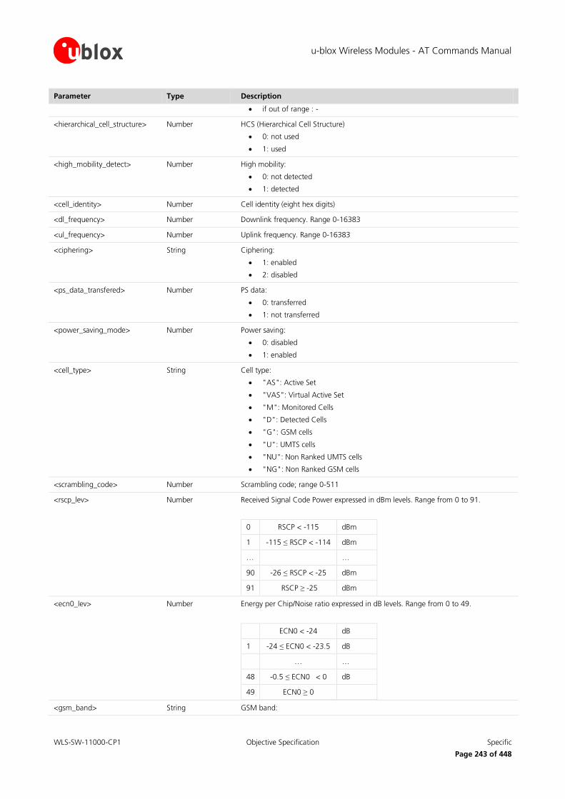
u-blox Wireless Modules - AT Commands Manual
WLS-SW-11000-CP1 Objective Specification Specific
Page 243 of 448
Parameter Type Description
if out of range : -
<hierarchical_cell_structure> Number HCS (Hierarchical Cell Structure)
0: not used
1: used
<high_mobility_detect> Number High mobility:
0: not detected
1: detected
<cell_identity> Number Cell identity (eight hex digits)
<dl_frequency> Number Downlink frequency. Range 0-16383
<ul_frequency> Number Uplink frequency. Range 0-16383
<ciphering> String Ciphering:
1: enabled
2: disabled
<ps_data_transfered> Number PS data:
0: transferred
1: not transferred
<power_saving_mode> Number Power saving:
0: disabled
1: enabled
<cell_type> String Cell type:
"AS": Active Set
"VAS": Virtual Active Set
"M": Monitored Cells
"D": Detected Cells
"G": GSM cells
"U": UMTS cells
"NU": Non Ranked UMTS cells
"NG": Non Ranked GSM cells
<scrambling_code> Number Scrambling code; range 0-511
<rscp_lev> Number Received Signal Code Power expressed in dBm levels. Range from 0 to 91.
0 RSCP < -115 dBm
1 -115 ≤ RSCP < -114 dBm
… …
90 -26 ≤ RSCP < -25 dBm
91 RSCP ≥ -25 dBm
<ecn0_lev> Number Energy per Chip/Noise ratio expressed in dB levels. Range from 0 to 49.
ECN0 < -24 dB
1 -24 ≤ ECN0 < -23.5 dB
… …
48 -0.5 ≤ ECN0 < 0 dB
49 ECN0 ≥ 0
<gsm_band> String GSM band:

u-blox Wireless Modules - AT Commands Manual
WLS-SW-11000-CP1 Objective Specification Specific
Page 244 of 448
Parameter Type Description
"D": 1800 MHz
"P": 1900 MHz
"G": 900 MHz
<ranking_value> Number Cell’s ranking value
<ranking_status> Number Ranking status for Non Ranked UMTS cells. Possible values:
0: EM_CELL_SUITABLE
1: EM_NOT_MEASURED
2: EM_CELL_BARRED
3: EM_WRONG_PLMN
4: EM_HCS_CRITERIA_PRIO
5: EM_HCS_H_VALUE
6: EM_S_VALUE
<meas_id> Number RR measurement ID (one hex digit). For debug purpose only
<event_id> Number Event ID (two hex digits). For debug purpose only
<par 3,4,5..,M,..,N> Number Integer, range 0-99
<signal_failure/radio_link_counter>
Number Integer, range 0-99. For debug purpose only
<reselection_reason> Number Indicates the reason for cell reselection. Possible values:
0: RESEL_PLMN_CHANGE
1: RESEL_SERV_CELL_NOT_SUITABLE
2: RESEL_BETTER_C2_C32
3: RESEL_DOWNLINK_FAIL
4: RESEL_RA_FAILURE
5: RESEL_SI_RECEIPT_FAILURE
6: RESEL_C1_LESS_NULL
7: RESEL_CALL_REEST_TIMEOUT
8: RESEL_ABNORMAL_RESEL
9: RESEL_CELL_CHANGE_ORDER
10: RESEL_NOT_OCCURRED
<dl_sc>/<ul_sc> Number Current burst configuration and Coding Scheme of downlink (<dl_sc>) or uplink (<ul_sc>) TBF may be:
“NB_CS_1“
“NB_CS_2“
“NB_CS_3“
“NB_CS_4“
“NB_MCS_1“
“NB_MCS_2“
“NB_MCS_3“
“NB_MCS_4“
“NB_MCS_5“
“NB_MCS_6“
“NB_MCS_7“
“NB_MCS_8“
“NB_MCS_9“
“NB_MCS_5_7“
“NB_MCS_6_9“
“AB_8“
“AB_11“

u-blox Wireless Modules - AT Commands Manual
WLS-SW-11000-CP1 Objective Specification Specific
Page 245 of 448
Parameter Type Description
“AB_11_E“
if none of the previous “”
UMTS/GSM MM parameters:
Parameter Type Description
<mm_state> Number MM state. For debug purpose only. Range 1-16
<mm_service_state> Number MM service state. For debug purpose only. Range1-10.
<mm_update_status> Number location update status. For debug purpose only. Possible values:
1: updated (MMST_U1_UPDATED)
2: not updated (MMST_U2_NOT_UPDATED)
3: roaming not allowed (MMST_U3_ROAMING_NOT_ALLOWED)
<ms_class> String MS GPRS-class. Possible values:
0: class A
1: class B
2: class C
3: class CG: class C in GPRS only mode
4: class CC: class C in circuit switched only mode (lowest class)
<limited_service> Number Limited Service information. Possible values:
0: no Limited service
1: Limited Service
<ready_state> Number MM READY state. Possible values:
0: not in ready state
1: in ready state
<active_timer_bitmap> Number Bitmap of the active MM timers: T3302, T3310, T3311, T3312, T3314, T3321, T3330.
T3302 is the least significant bit and T3330 the most significant bit
The bitmap values are presented in hexadecimal format (the range goes from 0x0000 to 0x007F)
<cell_reselection_total> Number Total number of cell reselections. Range 0 – 65535.
<ir_cell_reselection_counter> Number Number of inter-rat cell reselections. Range 0 – 65535.
<attempted_ir_cell_reselction> Number Number of attempts of inter-rat cell reselections. Range 0 – 65535.
<ir_handover> Number Number of inter-rat handovers. Range 0 – 65535.
<attempted_ir_handover> Number Number of attempts of inter-rat handovers. Range 0 – 65535.
17.23 Device class setting +UCLASS
17.23.1 Description
Changes the module’s multislot classes. The new configuration cannot be set if the module is registered on the network for the GPRS service: in this case, before changing the multislot class, the user must first trigger a GPRS
detach (e.g. via +COPS=2 or +CGATT=0) otherwise an error is reported; the new multislot class is used starting
from the successive GPRS attach. The new multislot classes are also stored to NVM and used at next power on.
Type Syntax Response Example
Set AT+UCLASS=<ms_class_GPRS>[,<ms_class_EGPRS>[,<ms_class_DTM_GPRS>[,<ms_class_DTM_EGPRS>]]]
OK AT+UCLASS=10
OK

u-blox Wireless Modules - AT Commands Manual
WLS-SW-11000-CP1 Objective Specification Specific
Page 246 of 448
Type Syntax Response Example
Read AT+UCLASS? +UCLASS: <ms_class_GPRS>[,<ms_class_EGPRS>[,<ms_class_DTM_GPRS>[,<ms_class_DTM_EGPRS>]]]
OK
+UCLASS: 12,12,11,11
OK
Test AT+UCLASS=? +UCLASS: (list of supported <ms_class_GPRS> values)[,(list of supported <ms_class_EGPRS> values)[,(list of supported <ms_class_DTM_GPRS> values)[,(list of supported <ms_class_DTM_EGPRS> values)]]]
OK
+UCLASS: (0-12),(0-12),(0-11),(0-11)
OK
17.23.2 Defined values
Parameter Type Description
<ms_class_GPRS> Number GPRS multislot class defined according to 3GPP TS 05.02 [42]. Range from 0 to 12 (from 0 to 33 on LISA-U200-00S version; from 0 to 10 on LEON-G100 / LEON-G200 / SARA-G350 series). Factory-programmed value is 12 (10 on LEON-G100 / LEON-G200 / SARA-G350 series).
<ms_class_EGPRS> Number EGPRS multislot class defined according to 3GPP TS 05.02 [42]. Range from 0 to 12 (from 0 to 33 on LISA-U200-00S version). Factory-programmed value is 12. Default value is the value set in <ms_class_GPRS>.
<ms_class_DTM_GPRS> Number DTM GPRS multislot class defined according to 3GPP TS 05.02 [42]. Range from 0 to 11. Not available on LISA-U200-00S version. Factory-programmed value is 11. Default value is the value set in <ms_class_GPRS>.
<ms_class_DTM_EGPRS> Number DTM EGPRS multislot class defined according to 3GPP TS 05.02 [42]. Range from 0 to 11. Not available on LISA-U200-00S version. Factory-programmed value is 11. Default value is the value set in <ms_class_GPRS>.
In the set command <ms_class_GPRS>=0 is used to set the maximum supported values.
<ms_class_EGPRS> is not available on LEON-G100 / LEON-G200 / SARA-G350 series.
<ms_class_DTM_GPRS> and <ms_class_DTM_EGPRS> are not available on LEON-G100 / LEON-G200 /
SARA-G350 series, LISA-U1 series and LISA-U200-00S version.
LISA-U1 series requires the <ms_class_EGPRS> parameter in the set command.
LEON-G100 / LEON-G200 / SARA-G350 series does not allow <ms_class_GPRS>=7.
On LISA-U2 series module (except for LISA-U200-00S) if <ms_class_GPRS>=0 the default values are set for all parameters, regardless of the settings of the other parameter.
On LISA-U200-00S version, if <ms_class_GPRS>=0 the maximum supported values are set for all
parameters, regardless of the second parameter’s settings.
The GPRS, EGPRS, DTM GPRS and DTM EGPRS multislot classes cannot be independently chosen (some
configurations are not valid and an error is reported: “+CME ERROR: operation not supported” if +CMEE is set to 2). See the following tables:
Type Valid values Maximum value Default value
E/GPRS (1-12), (30-33) for LISA-U200-00S
(1-12) for LISA-U1 / LISA-U2 series except
LISA-U200-00S
33, for LISA-U200-00S
12, for LISA-U1 / LISA-U2 series except
LISA-U200-00S
12
DTM E/GPRS 5, 9,11 11 11
Table 9: Multislot classes: valid, maximum and default values for each type

u-blox Wireless Modules - AT Commands Manual
WLS-SW-11000-CP1 Objective Specification Specific
Page 247 of 448
GPRS Multislot class EGPRS Multislot class valid values
(1-12) (1-12)
30 30, 32, 33
31 31
32 30, 32, 33
33 30, 32, 33
Table 10: EGPRS multislot classes valid values relative to the selected GPRS multislot class
DTM EGPRS/GPRS Multislot class EGPRS/GPRS Multislot class valid values
5 (1-12)
9 (1-12)
11 (1-12)
Table 11: EGPRS/GPRS multislot classes valid values relative to the selected DTM EGPRS/GPRS multislot class
17.24 Read counters of sent or received PSD data +UGCNTRD
17.24.1 Description
Allows reading the counters for total sent / received bytes for each defined context.
For each active <cid> one result code line is provided by the DCE.
Only if the specific PDP context parameter values for a PDP context are set.
Type Syntax Response Example
Action AT+UGCNTRD +UGCNTRD: <cid>,<sent_sess_bytes>,<received_sess_bytes>,<sent_total_bytes>,<received_total_bytes>
[…
+UGCNTRD: <cid>,<sent_sess_bytes>,<received_sess_bytes>,<sent_total_bytes>,<received_total_bytes>]
OK
AT+UGCNTRD
+UGCNTRD: 1, 100, 0, 100, 0
OK
Test AT+UGCNTRD=? OK
17.24.2 Defined values
Parameter Type Description
<cid> Number Local PDP context identifier in the range of 0-255
<sent_sess_bytes> Number Sent bytes for the current PSD session
<received_sess_bytes> Number Received GPRS session bytes for the current PSD session
<sent_total_bytes> Number Total sent bytes
<received_total_bytes> Number Total received bytes

u-blox Wireless Modules - AT Commands Manual
WLS-SW-11000-CP1 Objective Specification Specific
Page 248 of 448
17.25 Set/reset counter of sent or received PSD data +UGCNTSET
17.25.1 Description
Allows setting the counter for total sent/received bytes for each defined context to zero or any other offset value.
Whenever the total counter for a <cid> is set (to zero or a certain value), the session counter for this
<cid> will be set to zero.
If the <cid> equals zero than the total counter for every defined context is set to zero.
Given offset parameters are ignored in this case.
Type Syntax Response Example
Set AT+UGCNTSET=<cid>,[<total_bytes_sent_offset>,<total_bytes_received_offset>]
OK AT+UGCNTSET=0,20,20
OK
Test AT+UGCNTSET=? +UGCNTSET: (range of <cid>s),(range of <total_bytes_sent_offset>),(range of <total_bytes_received_offset>)
OK
+UGCNTSET: (0-255),(0-2147483646),(0-2147483646)
OK
17.25.2 Defined values
Parameter Type Description
<cid> Number Number containing the local PDP context identifier in range of 0-255
<total_bytes_sent_offset> Number Long number containing the offset of total sent bytes used for counting in range 0-0x7FFFFFFE
<total_bytes_received_offset> Number Long number containing the offset of total received bytes used for counting in range 0-0x7FFFFFFE.
17.26 Read remaining SIM PIN attempts +UPINCNT
17.26.1 Description
Reads the remaining attempts for SIM PIN, SIM PIN2, SIM PUK and SIM PUK2.
Type Syntax Response Example
Action AT+UPINCNT +UPINCNT: <PIN attempts>, <PIN2 attempts>, <PUK attempts>, <PUK2 attempts>
OK
+UPINCNT: 3,3,10,10
OK
Test AT+UPINCNT=? OK OK
17.26.2 Defined values
Parameter Type Description
<PIN attempts> Number Number of remaining attempts to enter PIN
<PIN2 attempts> Number Number of remaining attempts to enter PIN2
<PUK attempts> Number Number of remaining attempts to enter PUK

u-blox Wireless Modules - AT Commands Manual
WLS-SW-11000-CP1 Objective Specification Specific
Page 249 of 448
Parameter Type Description
<PUK2 attempts> Number Number of remaining attempts to enter PUK2
17.27 Help displaying all commands &H
17.27.1 Description
This command allows to list all possible commands.
Type Syntax Response Example
Action AT&H <AT command 1>[: <AT command 1 title>][, <CR><LF> <AT command 2>[: <AT command 2 title>]
[…]]
OK
ATA : Answer an Incoming Call
ATE : Echo
ATH : Hook Control
ATV : Enable/Disable verbose response
…
AT+UTEST : End User Test
ATS : Query or Set an S-register
ATD : Dial
OK
17.27.2 Defined values
Parameter Type Description
<AT command n> String AT command name
<AT command n title> String AT command title
<AT command n title> is not supported on LEON-G100/LEON-G200 series.
17.28 Provide Cell information +UCELLINFO
17.28.1 Description
This command provides periodic reporting of the serving and neighbor cells.
Type Syntax Response Example
Set AT+UCELLINFO=<mode> OK AT+UCELLINFO=1
OK

u-blox Wireless Modules - AT Commands Manual
WLS-SW-11000-CP1 Objective Specification Specific
Page 250 of 448
Type Syntax Response Example
Read AT+UCELLINFO? Response syntax in case of 2G radio access technology (RAT):
+UCELLINFO: <mode>,<type>,<MCC>,<MNC>,<LAC>,<CI>,[RxLev],[t_advance]
OK
Response syntax in case of 3G radio access technology (RAT):
+UCELLINFO: <mode>,<type>,<MCC>,<MNC>,<LAC>,<CI>,[<scrambling_code>],[<dl_frequency>],<rscp_lev>,[<ecn0_lev>]
OK
Test AT+UCELLINFO=? +UCELLINFO: (range of <mode>s)
OK
+UCELLINFO: (0-2)
OK
17.28.2 Defined values
Parameter Type Description
<mode> Number 0: disable the periodic reporting
1: enable the reporting
2: reserved
<type> Number For 2G radio access technology (RAT):
0: 2G serving cell
1: neighbour 2G cell
For 3G radio access technology (RAT):
2: 3G serving cell or cell belonging to the Active Set
3: cell belonging to the Virtual Active Set
4: detected cell
<MCC> Number See +CGED; 0, 0xFFFF, 65535 are invalid values
<MNC> Number See +CGED; 0, 0xFFFF, 65535 are invalid values
<LAC> Number Location Area Code, range 0-0xFFFF; 0, 65535, 0xFFFF are invalid values
<CI> Number Cell ID, range 0-0xFFFF; 0, 65535, 0xFFFF are invalid values
<RxLev> Number Signal strength, see +CGED; 255 is an invalid value
<t_advance> Number Only valid for the 2G serving cell
<scrambling_code> Number See +CGED; values greater than 512 are invalid
<dl_frequency> Number See +CGED; 65535 is an invalid value
<rscp_lev> Number See +CGED; only valid for 3G cells; 255 is an invalid value
<ecn0_lev> Number See +CGED; only valid for 3G cells; 255 is an invalid value
If the MT is 3G registered with an active radio connection (CELL_DCH):
o <MCC>, <MNC>, <LAC> and <CI> will be always invalid for 3G cells belonging to Active Set,
Virtual Active Set, Detected Set
o The 3G serving cell data could be outdated. Use the Active Set data for any information
regarding involved cells in the current radio connection

u-blox Wireless Modules - AT Commands Manual
WLS-SW-11000-CP1 Objective Specification Specific
Page 251 of 448
17.29 Configuration of Indicator control +UCIND
17.29.1 Description
Allows the configuration of unsolicited results for indications with +CIEV.
Type Syntax Response Example
Set AT+UCIND=[<conf>] OK AT+UCIND=7
OK
Read AT+UCIND? +UCIND: <conf>
OK
+UCIND: 7
OK
Test AT+UCIND=? OK
17.29.2 Defined values
Parameter Type Description
<conf> Number The unsigned integer is a bit array where each bit indicates if an indication is active for unsolicited indications. The least significant bit is used for the indication with index 1.
The bit corresponding to unused indexes (greater than 13) must be set to 0 (setting a <conf> greater than 4095 causes an error). The default value is 4095 (all indications are enabled).
17.30 Customer service profile +UCSP
17.30.1 Description
Reads the customer service profile (CSP) from the SIM. The CSP indicates the services that are user accessible.
The syntax +UCSP displays all service groups.
If CSP information isn't available on the SIM, the error message “+CME ERROR: SIM Failure” is returned when trying to interrogate all or one of the service groups.
Type Syntax Response Example
Set AT+UCSP[=<service group>] +UCSP: <service_group>,<services>
[+UCSP: <service_group>,<services>
[…]]
OK
+UCSP=06,10000000
OK
Test AT+UCSP=? +UCSP: (list of supported <service group>s)
OK
+UCSP: (1-9,c0,d5)
OK
17.30.2 Defined values
Parameter Type Description
<service_group> Number Service group (1-9, c0, d5)
<services> Number Services of one service group in bit-format beginning with the most significant bit of the service byte

u-blox Wireless Modules - AT Commands Manual
WLS-SW-11000-CP1 Objective Specification Specific
Page 252 of 448
17.31 User setting for proactive DTMF tone generation +UDTMF
17.31.1 Description
On a request from SIM Toolkit of proactive DTMF tone generation (SEND DTMF), <mode> parameter controls wheter the request of DTMF tone generation is performed or it is not. The selected setting is stored in NVRAM
and remains valid after the mobile device is switched off.
Not supported by LISA-U200-00S version.
Type Syntax Response Example
Set AT+UDTMF=<mode> OK AT+UDTMF=1
OK
Read AT+UDTMF? +UDTMF: <mode>
OK
+UDTMF: 1
OK
Test AT+UDTMF=? +UDTMF: (list of supported <mode>s)
OK
+UDTMF: (0-1)
OK
17.31.2 Defined values
Parameter Type Description
<mode> Number Indicates the working mode in relation to DTMF tone generation via SIM-TK
0: disable DTMF tone generation (The terminal response is “Proactive SIM session terminated by user”)
1: enable DTMF tone generation (The terminal response is encoded according to the result)
17.32 Changing the startup MS class +UCGCLASS
17.32.1 Description
Controls the MS class value used at startup. The new class entered with the set command will be stored to NVM
and used in the next power on.
Type Syntax Response Example
Set AT+UCGCLASS=<class> OK AT+UCGCLASS="CC"
OK
Read AT+UCGCLASS? +UCGCLASS: <class>
OK
+UCGCLASS: "B"
OK
Test AT+UCGCLASS=? +UCGCLASS: (list of supported <mode>s)
OK
+UCGCLASS: ("B","CC")
OK
17.32.2 Defined values
Parameter Type Description
<class> String "B" (factory-programmed setting): class B mode of operation (the MT

u-blox Wireless Modules - AT Commands Manual
WLS-SW-11000-CP1 Objective Specification Specific
Page 253 of 448
Parameter Type Description
supports both circuit-switched and packet-switched services)
"CC": class C mode of operation (the MT supports only circuit switched services)
If “CC” is selected, the network selection (+COPS AT command) triggers a registration only for CS
services.
If “CC” is selected, +CGATT=1 forces the registration for PS services (i.e. +UCGCLASS’ setting is
ignored)
17.33 Generic SIM access +CSIM
17.33.1 Description
Allows direct control of the SIM by a distant application on the TE. This command transparently transmits the
<command> to the SIM via the MT. The <response> is returned in the same manner to the TE.
It is recommended to wait some seconds after boot (or reset) before using AT+CSIM command.
Type Syntax Response Example
Set AT+CSIM=<length>,<command> +CSIM: <length>,<response>
OK
AT+CSIM=4,"4330"
+CSIM: 4,"6F00"
OK
Test AT+CSIM=? OK OK
17.33.2 Defined values
Parameter Type Description
<length> Number Length of the characters that are sent to TE in <command> or <response>
<command> String Command passed on by MT to SIM in hex format; refer to 3GPP TS 51.011 [18]
<response> String Response to the command passed on by the SIM to the MT (3GPP TS 51.011 [18])
17.34 Selection of preferred PLMN list +CPLS
17.34.1 Description
Selects one PLMN selector with Access Technology list in the SIM card or active application in the UICC (GSM or USIM), that is used by +CPOL command.
The set command selects a list in the SIM/USIM. The read command returns the selected PLMN selector list from
the SIM/USIM
The test command returns the whole index range supported lists by the SIM/USIM.
Type Syntax Response Example
Set AT+CPLS=[<list>] OK
Read AT+CPLS? +CPLS: <list>
OK
+CPLS: 1
OK

u-blox Wireless Modules - AT Commands Manual
WLS-SW-11000-CP1 Objective Specification Specific
Page 254 of 448
Type Syntax Response Example
Test AT+CPLS=? +CPLS: (list of supported <list>s)
OK
+CPLS: (0-2)
OK
17.34.2 Defined values
Parameter Type Description
<list> Number 0: User controlled PLMN selector with Access Technology EFPLMNwAcT, if not found in the SIM/UICC then PLMN preferred list EFPLMNsel (this file is only available in SIM card or GSM application selected in UICC)
1: Operator controlled PLMN selector with Access Technology EFOPLMNwAcT
2: HPLMN selector with Access Technology EFHPLMNwAcT
17.35 Read the SIM language +CLAN
17.35.1 Description
This command reads the language from the SIM.
The read syntax will display the most preferred language from the preferred language list in
EF_ELP(2F05) file. If the EF_ELP file does not exist, the preferred language is read from EF_LP (6F05) file.
This file content is decoded according to the CB (cell broadcast) data coding scheme (dcs), and the
according language is displayed in the response string. If this byte does not result in a valid language according to the CB dcs, then it is printed in the response string in hexadecimal representation.
Type Syntax Response Example
Read AT+CLAN? +CLAN: <code>
OK
+CLAN: "en"
OK
Test AT+CLAN=? OK
17.35.2 Defined values
Parameter Type Description
<code> String It is a two-letter abbreviation of the language. The language codes, as defined in ISO 639, consists of two characters, e.g. "en", "it" etc
17.36 Check for UICC card +UUICC
17.36.1 Description
Determines if the current SIM is a 2G or 3G SIM.
Type Syntax Response Example
Read AT+UUICC? +UUICC: <state>
OK
+UUICC: 1
OK

u-blox Wireless Modules - AT Commands Manual
WLS-SW-11000-CP1 Objective Specification Specific
Page 255 of 448
17.36.2 Defined values
Parameter Type Description
<state> Number 0: 2G SIM
1: 3G SIM
17.37 Home zone reporting +UHOMEZR
17.37.1 Description
The set command enables and disables home zone change event reporting. If reporting is enabled, the MT returns URC +UHOMEZR: <label> whenever the home zone is changed.
Type Syntax Response Example
Set AT+UHOMEZR=<onoff> OK AT+UHOMEZR=1
OK
Read AT+UHOMEZR? +UHOMEZR: <onoff>
OK
Test AT+UHOMEZR=? +UHOMEZR: (list of supported <onoff>s)
OK
+UHOMEZR: (0-1)
OK
URC +UHOMEZR: <label>
17.37.2 Defined values
Parameter Type Description
<onoff> Number 0 (default value): disable home zone change event reporting
1: enable home zone change event reporting
<label> String Zone label indication
“HOME”: also possible as “home”, dependent from network indication
“CITY”: zone label
17.38 Configure the mode of HSDPA/HSUPA +UHSDUPA
17.38.1 Description
Enables / Disables HSDPA and HSUPA also configuring the related data rate. The settings are saved in NVM at power off; the new configuration will be effective at the next power on.
Type Syntax Response Example
Set AT+UHSDUPA=<HSDPA-mode>,<HS-DSCH_category>,<HSUPA-mode>[,<E-DCH category>]
OK AT+UHSDUPA=1,8,1,6
OK
Read AT+UHSDUPA? +UHSDUPA: <HSDPA-mode>,<HS-DSCH_category>,<HSUPA-mode>,<E-DCH category>
OK
+UHSDUPA: 1,8,1,6
OK

u-blox Wireless Modules - AT Commands Manual
WLS-SW-11000-CP1 Objective Specification Specific
Page 256 of 448
Type Syntax Response Example
Test AT+UHSDUPA=? +UHSDUPA: (<list of supported <HSDPA-mode>s),(<list of supported <HS-DSCH_category>s>),(<list of supported <HSUPA-mode>s),(<list of supported>,<E-DCH category>s)
OK
On LISA-U1 series:
+UHSDUPA: (0-1),(6,8),(0-1),(1,2,4,6)
OK
On LISA-U2 series:
+UHSDUPA: (0-1),(6,8,10,12,13,14),(0,1),(1,2,6)
OK
17.38.2 Defined values
Parameter Type Description
<HSDPA-mode> Number 0: HSDPA OFF
1 (default value): HSDPA ON
<HS-DSCH_category> Number HS-DSCH category defined in 3GPP TS 25.306 [53]
6: category 6
8 (default value for LISA-U1 series and LISA-U200, LISA-U260, LISA-U270): category 8
10: category 10
12: category 12
13: category 13
14 (default value for LISA-U230 products): category 14
<HSUPA-mode> Number 0: HSUPA OFF
1 (default value): HSUPA ON
<E-DCH category> Number E-DCH category defined in 3GPP TS 25.306 [53]
1: category 1
2: category 2
4: category 4
6 (default value): category 6
For LISA-U1 series, LISA-U200, LISA-U260 and LISA-U270 products the <HS-DSCH_category> range goes from 6 to 8.
For LISA-U230 versions the <HS-DSCH_category> range goes from 6 to 14.
<E-DCH category> =4 is not supported by LISA-U2 series except for LISA-U200-00S.
17.39 Information to in-band-tones availability +UPROGRESS
17.39.1 Description
Enables or disables the display of URC +UPROGRESS: <cin>,<status> on the DTE while a call is in progress.
Type Syntax Response Example
Set AT+UPROGRESS=<mode> OK AT+UPROGRESS=1
OK
Read AT+UPROGRESS? +UPROGRESS: <mode>
OK
+UPROGRESS: 1
OK
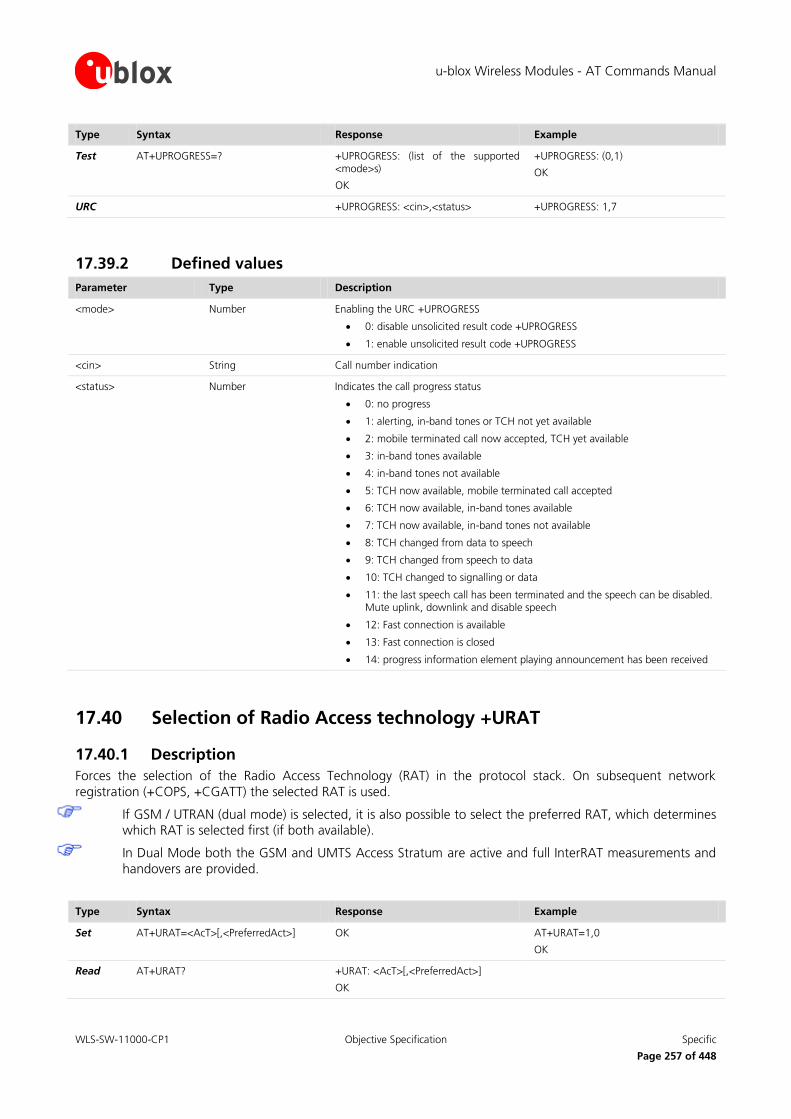
u-blox Wireless Modules - AT Commands Manual
WLS-SW-11000-CP1 Objective Specification Specific
Page 257 of 448
Type Syntax Response Example
Test AT+UPROGRESS=? +UPROGRESS: (list of the supported <mode>s)
OK
+UPROGRESS: (0,1)
OK
URC +UPROGRESS: <cin>,<status> +UPROGRESS: 1,7
17.39.2 Defined values
Parameter Type Description
<mode> Number Enabling the URC +UPROGRESS
0: disable unsolicited result code +UPROGRESS
1: enable unsolicited result code +UPROGRESS
<cin> String Call number indication
<status> Number Indicates the call progress status
0: no progress
1: alerting, in-band tones or TCH not yet available
2: mobile terminated call now accepted, TCH yet available
3: in-band tones available
4: in-band tones not available
5: TCH now available, mobile terminated call accepted
6: TCH now available, in-band tones available
7: TCH now available, in-band tones not available
8: TCH changed from data to speech
9: TCH changed from speech to data
10: TCH changed to signalling or data
11: the last speech call has been terminated and the speech can be disabled. Mute uplink, downlink and disable speech
12: Fast connection is available
13: Fast connection is closed
14: progress information element playing announcement has been received
17.40 Selection of Radio Access technology +URAT
17.40.1 Description
Forces the selection of the Radio Access Technology (RAT) in the protocol stack. On subsequent network
registration (+COPS, +CGATT) the selected RAT is used.
If GSM / UTRAN (dual mode) is selected, it is also possible to select the preferred RAT, which determines which RAT is selected first (if both available).
In Dual Mode both the GSM and UMTS Access Stratum are active and full InterRAT measurements and
handovers are provided.
Type Syntax Response Example
Set AT+URAT=<AcT>[,<PreferredAct>] OK AT+URAT=1,0
OK
Read AT+URAT? +URAT: <AcT>[,<PreferredAct>]
OK

u-blox Wireless Modules - AT Commands Manual
WLS-SW-11000-CP1 Objective Specification Specific
Page 258 of 448
Type Syntax Response Example
Test AT+URAT=? +URAT: (list of the supported <AcT>s),(list of the supported <PreferredAct>s)
OK
+URAT: (0-2), (0,2)
OK
17.40.2 Defined values
Parameter Type Description
<AcT> Number Indicates the radio access technology and may be:
0: GSM (single mode)
1 (factory-programmed setting): GSM / UTRAN (dual mode)
2: UTRAN (single mode)
<PreferredAct> Number This parameter indicates the preferred access technology; it is ignored if dual mode (<AcT>=1) is not selected.
0: GSM
2 (default value and factory-programmed setting): UTRAN
The command settings are stored in the non volatile memory.
Any change in the RAT selection must be done in detached state!
17.41 Extended Packet Switched network registration status +UREG
17.41.1 Description
Reports the network or the device PS (Packet Switched) radio capabilities.
When the device is not in connected mode, +UREG reports the network PS (Packet Switched) radio capabilities of the PLMN where the device is attached to.
When the device is in connected mode, +UREG reports the PS radio capabilities the device has been configured.
The set command allows to enable / disable the URC +UREG, generated whenever it is enabled and the capabilities change.
The read command can be used to query the current PS radio capabilities.
<state>= 8 and 9 is not supported by LISA-U1 series or by LISA-U200-00S version.
Type Syntax Response Example
Set AT+UREG=<n> OK AT+UREG=1
OK
Read AT+UREG? +UREG: <n>,<state>
OK
Test AT+UREG=? +UREG: (list of supported <n>’s)
OK
URC +UREG: <state>

u-blox Wireless Modules - AT Commands Manual
WLS-SW-11000-CP1 Objective Specification Specific
Page 259 of 448
17.41.2 Defined values
Parameter Type Description
<n> Number 0: disable network registration attach status URC
1: enable network registration attach status URC +UREG
<state> Number 0: not registered for PS service
1: registered for PS service, RAT=2G, GPRS available
2: registered for PS service, RAT=2G, EDGE available
3: registered for PS service, RAT=3G, WCDMA available
4: registered for PS service, RAT=3G, HSDPA available
5: registered for PS service, RAT=3G, HSUPA available
6: registered for PS service, RAT=3G, HSDPA and HSUPA available
7: reserved
8: registered for PS service, RAT=2G, GPRS available, DTM available
9: registered for PS service, RAT=2G, EDGE available, DTM available
17.42 Start and stop tone generation +UVTS
17.42.1 Description
Starts and stops DTMF tones. In GSM this operates only in voice mode.
Type Syntax Response Example
Set AT+UVTS=[<DTMF>] OK AT+UVTS=2
OK
Test AT+UVTS=? +UVTS: (list of <DTMF>s)
OK
+UVTS: (0-9,#,*,A-D)
OK
When <DTMF> parameter is omitted the tone is stopped.
The list of supported <DTMF>s is not provided by the test command response of LISA-U1x0-00S
versions.
17.42.2 Defined values
Parameter Type Description
<DTMF> Char Single ASCII character in the set 0-9, #, *, A-D
If the command is invoked when not in a call, an error is reported (“+CME ERROR: no connection to
phone” if +CMEE set to 2).

u-blox Wireless Modules - AT Commands Manual
WLS-SW-11000-CP1 Objective Specification Specific
Page 260 of 448
17.43 PCCA STD-101 [17] select wireless network +WS46
17.43.1 Description
PCCA STD-101 [17] includes a command to select the cellular network (Wireless Data Service; WDS) to operate with the MT. PCCA calls this WDS-Side Stack Selection. This command may be used when the MT is asked to
indicate the networks in which it can operate.
Type Syntax Response Example
Set AT+WS46=[<n>] OK AT+WS46=25
OK
Read AT+WS46? +WS46: <n>
OK
+WS46: 25
OK
Test AT+WS46=? +WS46: (list of supported <n>s)
OK
+WS46: (12,22,25)
OK
17.43.2 Defined values
Parameter Type Description
<n> Number WDS-Side Stack Selection indication and may be:
12: GSM digital cellular (Single mode GSM)
22: UTRAN only (Single mode UMTS)
25: 3GPP Systems, both GERAN and UTRAN (Dual Mode Stack)
Any change in the WDS-Side stack selection must be done during detached state.
This functionality is also supported by the proprietary command +URAT, which provides extended functionality to +WS46.
17.44 End User Test +UTEST
17.44.1 Description
Sets the module in non-signalling (or test) mode, or returns to signalling (or normal) mode.
In test/non-signalling mode the module switches off the 2G/3G protocol stack for performing single tests which could not be performed during signalling, since the radio frequency part is directly controlled by the test.
When entering test mode, it is possible to sequentially trigger the following actions for testing purposes:
2G Transmission of GSM burst sequence on the desired channel and power level (only 1 time slot configuration is available)
2G Transmission of 8PSK modulation burst sequence on the desired channel and power level (only 1 time slot configuration is available)
3G Transmission of WCDMA signal on the desired channel and power level
Receiving signal detection and RF level measurement on the desired 2G or 3G channel
Receiving signal detection at diversity antenna input and RF level measurement on the desired 2G or 3G
channel

u-blox Wireless Modules - AT Commands Manual
WLS-SW-11000-CP1 Objective Specification Specific
Page 261 of 448
The command only accepts the parameters set supported by the specific module version. When an unsupported parameter is entered an error message will be provided (“+CME ERROR: operation not
supported” if +CMEE is set to 2).
The execution of these actions is performed in non-signalling mode. In Normal mode:
The only allowed UTEST command is the AT+UTEST=1 used to enable testing interface in non-signalling
mode
All other UTEST commands return an error message (“+CME ERROR: operation not allowed” if +CMEE is set
to 2)
Before entering the non-signalling mode the <mode> parameter of AT+COPS command must be set to
2, otherwise an error message (“+CME ERROR: operation not allowed” if +CMEE is set to 2) is provided.
In non-signalling mode:
The module only accepts +UTEST commands
The +CMEE command can only be set in Normal mode.
To return to the normal mode one of these actions must be perfomed:
A module reset
Power off the module
Send AT+UTEST=0
Not supported by LEON-G100-05S / LEON-G200-05S and previous versions or by LISA-U1x0-00S
versions.
Type Syntax Response Example
Set AT+UTEST=<mode>,[<par1>],[<par2>],[<par3>],[<par4>],[<par5>]
+UTEST: [<par1>,<par2>][,<par3>,<par4>,<par5>][,<min>,<avg>,<max>]
OK
AT+UTEST=2,124,250
+UTEST: 124,250,-80,-80,-80
OK
Read AT+UTEST? +UTEST: <mode>
OK
+UTEST: 1
OK
Test AT+UTEST=? +UTEST: (list of supported <mode>s)
OK
+UTEST: (0-3)
OK
17.44.2 Defined values
Parameter Type Description
<mode> Number Test mode setting:
0: return to the module normal mode
1: the module enters non-signalling mode
2: RX test mode (measuring the antenna level estimation of the received RF signal)
3: TX test mode (GSMK/8PSK burst or transmission in 3G bands)
<par1>..<par5> Number Parameters needed for each selected mode as reported in the table below

u-blox Wireless Modules - AT Commands Manual
WLS-SW-11000-CP1 Objective Specification Specific
Page 262 of 448
RX mode setting (<mode>=2)
Par Description Range Default Notes
<par1> Channel 0 ÷ 65535 32 RX channel 2G mode: for 850, 900, 1800 bands the value corresponds to ARFCN while for 1900 band an offset of 32768 is added.
RX channel 3G mode: the value corresponds to UARFCN, additional channels available in some 3G bands are not supported.
For 2G mode:
[0-124]: GSM 900 MHz
[128-251]: GSM 850 MHz
[512-885]: DCS 1800 MHz
[975-1023]: EGSM 900 MHz
[33280-33578]: PCS 1900 MHz (corresponding to ARFCN 512-810 range in band 1900)
For 3G mode:
[1537 – 1738]: Band IV (1700 MHz)
[2937-3088]: Band VIII (900 MHz)
[4357-4458]: Band V (850 MHz) / Band VI (800 MHz) / Band XIX (800 MHz) (additional not supported, Band VI and XIX are subsets)
[9662-9938]: Band II (1900 MHz) (additional not supported)
[10562-10838]: Band I (2100 MHz)
Only the values indicated in the above ranges are valid, otherwise an error message will be provided (“+CME ERROR: operation not supported” if +CMEE is set to 2)
<par2> Time 1 ÷ 600000 1000 Time interval for RX test expressed in ms
<par3> Antenna Diversity 0 ÷ 1 0 Receiver path:
0: Main
1: Diversity
The parameter is available only if supported, otherwise an error message will be provided (“+CME ERROR: operation not supported” if +CMEE is set to 2)
<min> Minimum antenna RF level estimation
-100 ÷ -20 Expressed in dBm, for 2G mode
In 3G mode the range goes from -90 to -20
<avg> Average antenna RF level estimation
-100 ÷ -20 Expressed in dBm, for 2G mode
In 3G mode the range goes from -90 to -20
<max> Maximum antenna RF level estimation
-100 ÷ -20 Expressed in dBm, for 2G mode
In 3G mode the range goes from -90 to -20

u-blox Wireless Modules - AT Commands Manual
WLS-SW-11000-CP1 Objective Specification Specific
Page 263 of 448
RX mode test command examples
Command Response Description
AT+UTEST=2 +UTEST:32,1000,-89,-88,-87
OK
The module measures the antenna RX level at RX channel 32 band GSM900 for 1 s interval. After this time the module provides the response.
In the example -89,-88,-87 are the antenna RF level estimation: the numbers are just an example
AT+UTEST=2,885,5000 +UTEST:885,5000,-66,-65,-65
OK
The module measures the antenna RX level at RX channel 885 band DCS1800 for 5 s interval. After this time the module provides the response.
AT+UTEST=2,10562,2000 +UTEST:10562,2000,-60,-60,-59
OK
The module measures the antenna RX level at RX channel 10562 band B1 for 2 s interval on the main antenna path. After this time the module provides the response.
AT+UTEST=2,10562 +UTEST:10562,1000,0,-85,-85,-85
OK
The module measures the antenna RX level at RX channel 10562 band B1 for 1 s interval on the main antenna path. After this time the module provides the response.
AT+UTEST=2,65,3000,0 +UTEST:65,3000,0,-63,-62,-62
OK
The module measures the antenna RX level at RX channel 65 band GSM900 for 3 s interval on the main antenna path. After this time the module provides the response.
AT+UTEST=2,4357,,1 +UTEST:4357,1000,1,-51,-51,-51
OK
The module measures the antenna RX level at RX channel 4357 band B5 for 1 s interval on the diversity antenna path. After this time the module provides the response.
TX mode setting (<mode>=3)
Par Description Range Default Notes
<par1> Tx channel 0 ÷ 65535 32 TX channel 2G mode: for 850, 900, 1800 bands the value corresponds to ARFCN while for 1900 band an offset of 32768 is added.
TX channel 3G mode: the value corresponds to UARFCN, additional channels available in some 3G bands are not supported.
For 2G mode:
[0-124]: GSM 900 MHz
[128-251]: GSM 850 MHz
[512-885]: DCS 1800 MHz
[975-1023]: EGSM 900 MHz
[33280-33578]: PCS 1900 MHz (corresponding to ARFCN 512-810 range in band 1900)
For 3G mode:
[1312 - 1513]: Band IV (1700 MHz)
[2712-2863]: Band VIII (900 MHz)
[4132-4233]: Band V (850 MHz) / Band VI (800 MHz) / Band XIX (800 MHz) (additional not supported, Band VI and XIX are subsets)
[9262-9538]: Band II (1900 MHz) (additional not supported)
[9612-9888]: Band I (2100 MHz)
Only the values indicated in the above ranges are valid, otherwise an error message will be provided (“+CME ERROR: operation not supported” if +CMEE is set to 2)

u-blox Wireless Modules - AT Commands Manual
WLS-SW-11000-CP1 Objective Specification Specific
Page 264 of 448
Par Description Range Default Notes
<par2> Power control Level -56 ÷ 24 5 For 2G mode: PCL (power control level). The allowed values depend on the related <par1> value: lower numbers means higher power level.
[0-19]: GSM 850 and 900, if <par2> is less than 5 the handling is the same for <par2>=5
[0-15]: DCS 1800 and PCS 1900
In case <par4> is set to 2 (8PSK modulation) range is as below. Other values are valid but behave as indicated level
[0-19]: GSM 850 and 900 if <par2> is less than 8 the handling is the same for <par2>=8
[0-15]: DCS 1800 and PCS 1900; if <par2> is less than 2 the handling is the same for <par2>=2
For 3G mode: Absolute output power [dBm]
[-56 ÷ 24] for all bands
Only the values indicated in the above ranges are valid, otherwise a messager error will be provided (“+CME ERROR: operation not supported” if +CMEE was set to 2).
<par3> Training Seq (TSC) 0 ÷ 7 5 Training sequence to be used (to be changed only in case of link with network simulator, else use default)
In 3G mode the values is unused.
<par4> Modulation Mode 1 ÷ 2 1 Modulation mode
1: GMSK normal modulation including TSC
2: 8PSK normal modulation including TSC
In 3G mode the values is unused.
WCDMA modulation is automatically set using for <par1> a UARFCN value.
<par5> Time 0 ÷ 600000 1000 Time interval for TX test expressed in ms
0: burst sequence is continuously transmitted. In this case the command will immediately return. The command line will be immediately available for any +UTEST command. To stop the burst sequence transmission the command AT+UTEST=1 must be provided, any other UTEST commands can be set and current sequence transmission will be stopped.
TX mode test command examples
Command Response Description
AT+UTEST=3,32,7,5 +UTEST:32,7,5,1,1000
OK
The module transmits for 1 s interval 1 slot burst sequence at TX channel 32 GSM900 at PCL 5 using training sequence 5 and normal GMSK modulation
AT+UTEST=3,65,8,,2,5000 +UTEST:65,8,5,2,5000
OK
The module transmits for 5 s interval 1 slot burst sequence at TX channel 65 GSM900 at PCL 8 (gamma 6, 27 dBm) using training sequence 5 and normal 8PSK modulation
AT+UTEST=3,660,,,,0 +UTEST:660,5,5,1,0
OK
The module continuously transmits 1 slot burst sequence at TX channel 660 DCS1800 at PCL 5 using training sequence 5 and normal GMSK modulation

u-blox Wireless Modules - AT Commands Manual
WLS-SW-11000-CP1 Objective Specification Specific
Page 265 of 448
Command Response Description
AT+UTEST=3,9612,22,,,2000 +UTEST:9612,22,5,2,2000
OK
The module transmits for 2 s interval at TX channel 9612 band B1 at 22 dBm power level using WCDMA modulation
Example:
Command Response Description
AT+UTEST=1 OK
AT+UTEST? +UTEST: 1
OK
AT+UTEST=3,37,5,0,1,20000 +UTEST: 37,5,0,1,20000
OK
AT+UTEST=2,124,250 +UTEST: 124,250,-80,-80,-80
OK
AT+UTEST=2,37,5000 +UTEST: 37,5000,-100,-100,-100
OK
AT+UTEST=0 OK
17.45 Smart temperature Supervisor +USTS
17.45.1 Description
Allows to enable/disable the Smart Temperature Supervisor feature.
When the feature is enabled the internal temperature is measured via the internal temperature sensor.
If the measured value goes over the t+1
threshold or below the t-1 threshold an URC will be sent to notify a
warning: the module is still in a valid and good working condition.
If the measured value goes over the t+2
threshold or below the t-2 threshold an URC will be sent to notify the
dangerous working condition. This status will be notified and the device will start the shutting down procedure to avoid damaging it.
The shutting down procedure is performed only if <mode>=1: an URC is sent to notify this.
For security reasons the shut down is suspended in case of emergency call in progress. In this case the
device will switch off at call termination: an URC will be sent to notify this.
If the feature is disabled (<mode> = 0 and <mode> = 2) there’s no embedded protection against not
allowed temperature working conditions.
For more details on Smart Temperature Supervisor feature, refer to LEON-G100/G200 system Integration
Manual [25] or SARA-G350 Series System integration Manual [71] or LISA-U Series System integration Manual [49].
Type Syntax Response Example
Set AT+USTS=<mode> OK AT+USTS=0
OK
Read AT+USTS? +USTS: <mode>
OK
+USTS: 0
OK

u-blox Wireless Modules - AT Commands Manual
WLS-SW-11000-CP1 Objective Specification Specific
Page 266 of 448
Type Syntax Response Example
Test AT+USTS=? +USTS: (list of supported modes)
OK
+USTS: (0-2)
OK
URC +UUSTS: <mode>,<event> +UUSTS: 1,1
17.45.2 Defined values
Parameter Type Description
<mode> Number Enable / disable the smart temperature mode
0 (default value): feature disabled
1: Smart Temperature feature enabled: the indication and shutting down are performed
2: Smart Temperature Indication enabled
<event> Number Provides the event status
-2: temperature below t-2 threshold
-1: temperature below t-1 threshold
0: temperature inside the allowed range – not close to the limits
1: temperature above t+1 threshold
2: temperature above the t2threshold
10: timer expired and no emergency call is in progress, shutdown phase started
20: emergency call ended, shutdown phase started
100: error during measurement
<event>=100 is not supported by LEON-G100 / LEON-G200 / SARA-G350 series.
17.46 Configure the Data Channel +UDATACHANNEL
17.46.1 Description
Configures the serial channel over which CSD or PSD data shall be routed during a data connection (initiated by the ATD or AT+CGDATA commands), after the CONNECT has been received.
As a factory-programmed setting, the data is routed on the same channel where the connection is established.
The channels are identified by a string made up of a trailing forward slash followed by the device type name and
a numerical index, separated by a forward slash. For example:
"/USBCDC/0" is the 1st USB channel
"/tyCo/2" is the 3rd UART/SPI channel
"/mux/1" is the 2nd multiplexer channel
The MUX channels are available only if the mux is activated.
Channel identifier (Device name) Description
"/tyCo/0" UART 0
"/tyCo/2" SPI
"/USBCDC/0" USB channel #0
"/USBCDC/1" USB channel #1
"/USBCDC/2" USB channel #2

u-blox Wireless Modules - AT Commands Manual
WLS-SW-11000-CP1 Objective Specification Specific
Page 267 of 448
Channel identifier (Device name) Description
"/USBCDC/4" USB channel #4
"/mux/1" MUX channel #1
"/mux/2" MUX channel #2
"/mux/3" MUX channel #3
"/mux/4" MUX channel #4
"/mux/5" MUX channel #5
"/mux/6" MUX channel #6
"/mux/7" MUX channel #7
"/mux/8" MUX channel #8
An error message will be provided if the referenced channel is not active / available.
Type Syntax Response Example
Set AT+UDATACHANNEL=<mode>,<csd_psd_flag>,<ctrl-tid-path>,<tidpath>[,<connect_flag>]
OK AT+UDATACHANNEL=1,1,"/mux/1","/mux/2",0
Test AT+UDATACHANNEL=? +UDATACHANNEL: (list of <mode>s),(list of <csd_psd_flag>’s), (list of <connect_flag>’s)
OK
+UDATACHANNEL: (0-2),(0,1),(0,1)
OK
17.46.2 Defined values
Parameter Type Description
<mode> Number 0: disable the routing
1: enable the routing
2: query current setting for the type of data specified by <csd_psd_flag> and the channel referenced by <ctrl-tidpath>; the <tid-path> must not be set.
<csd_psd_flag> Number 0 configure the channel for a CSD connection
1 configure the channel for a PSD connection
<ctrl-tid-path> String Interface for which the data routing mechanism shall be enabled
<tid-path> String Interface to which a data call shall be routed
<connect_flag> Number 0 No Reporting on the data channel (neither CONNECT nor NO CARRIER)
1 Reporting on the data channel enabled (= CONNECT and NO CARRIER)
17.47 Custom SIM Lock +USIMLCK
17.47.1 Description
Allows locking the SIM to work only with user-defined sets of SIM cards (e.g. a subset of networks, with a specified SIM card). According to the 3GPP TS 22.022 [31] there are different kinds of lock as follows:
Network
Network Subset
SIM

u-blox Wireless Modules - AT Commands Manual
WLS-SW-11000-CP1 Objective Specification Specific
Page 268 of 448
Service Provider (not supported)
Corporate (not supported)
SIM is locked according to user needs even if the SIM card is not inserted or the PIN code is not provided. At
most 10 personalizations can be simultaneously configured.
Not supported by LEON-G100-05S / LEON-G200-05S and previous versions or by LISA-U1x0-00S
versions.
Type Syntax Response Example
Set AT+USIMLCK=<facility>,<pers_data>,<pwd>,<status>
OK AT+USIMLCK="PN","222.01","12345678",1
OK
Test AT+USIMLCK=? +USIMLCK: (list of supported <facility>s),,,(list of supported <status>)
OK
+USIMLCK: ("PN","PU","PS"),,,(0-1)
OK
17.47.2 Defined values
Parameter Type Description
<facility> String Personalization type, which can be:
"PN" Network personalization
"PU" Networks subset personalization
"PS" SIM/USIM personalization
<pers_data> String Data for device personalization. The contents depend on the selected <facility>.
On LEON-G100 / LEON-G200 / SARA-G350 series and on LISA-U200-00S version:
If <facility> is "PN":
<pers_data> contains at most 10 pairs of MCC and MNC in the following format: "MCC.MNC" separated by colons: "MCC1.MNC1:MCC2.MNC2:…:MCCn.MNCn"
If <facility> is "PU":
<pers_data> contains MCC + MNC + a list of at most 10 pairs of the digits 6 and 7 of IMSI; the format of the string is: "MCC.MNC:DD1:DD2:…:DDn" where DDx represent the sixth and seventh digits of IMSI
If <facility> is "PS":
<pers_data> contains a list of at most 10 IMSIs; the format of the string is: "IMSI1:IMSI2:…:IMSIn"
Otherwise:
If <facility> is "PN":
<pers_data> is in the format:
"MCC1.MNC1min[-MNC2max][,MCC2.MNC2min[-MNC2max]… [,MCC10.MNC10min[-MNC10max]]"
It contains a list of comma-separated pairs of MCCs and MNC ranges
If <facility> is "PU":
<pers_data> is in the format:
"MCC1.MNC1min[-MNC2max][,MCC2.MNC2min[-MNC2max]… [,MCC10.MNC10min[-MNC10max]]:MSIN1[,MSIN2…[,MSIN10]]"
It contains a list of comma-separated pairs of MCCs+MNC ranges as above; a list of comma-separated MSIN(s) or ranges of MSINs is

u-blox Wireless Modules - AT Commands Manual
WLS-SW-11000-CP1 Objective Specification Specific
Page 269 of 448
Parameter Type Description
appended after the MCC/MNC range using a ‘:’ as separator.
MSINs can be written with wildcards (‘*’) with the syntax: [*[*]]D1[D2[…]] (one wildcard for each MSIN digit to skip) followed by one or more digits.
It is possible to use ranges of MSIN digits; in this case the minimum and maximum values should have the same number of wildcard and the same number of digits.
In addition it is possible to concatenate more MSIN ranges with the comma separator (example: "123.456:56,**70-**72"). In this case all ranges must create a non empty set since MSIN comma separator behavior is an AND operator: an empty set means that any SIM is accepted
If <facility> is "PS":
<pers_data> contains a list of at most 10 IMSIs; the format of the string is: "IMSI1:IMSI2:…:IMSIn"
<pwd> String Password to enable/disable the personalization. The password length goes from 6 to 16 digits
<status> Number 0: feature set but disabled
1: feature set and enabled
The current personalization status can be queried using the AT+CLCK command with the proper facilities <fac> and the query status mode <mode>=2.
At the end of command execution, the module is deregistered from network, reset and rebooted.
A maximum of 5 attempts are allowed in case a wrong password is inserted during an unlock operation
with +CLCK command; after that, further unlock operations are blocked. The ME can still be used with
the right SIM.
The following error messages could be provided
o “+CME ERROR: invalid characters in text string“ (error code: 25): an error is present in the
<pers_data> format
o “+CME ERROR: operation not allowed“ (error code: 3): the user attempted the module
personalization with an already active facility. An unlock operation must be performed before.
Alternatively, an internal driver error occurred.
o “+CME ERROR: incorrect password“ (error code: 16): The password format or length is wrong
If the SIM lock is disabled it is possible to enable the lock with AT+CLCK command providing needed
parameters (<fac>, <mode>=1 and the password); otherwise the same personalization type can be
modified at any time by means of AT+USIMLCK command.
If the SIM lock is enabled the same personalization can be modified only if before it has been disabled
through AT+CLCK command.
17.48 Network Selection Control +PACSP
17.48.1 Description
Allows checking whether the EFCSP (Customer Service Profile) is available on the SIM/USIM card and, if available, what is the value of the PLMN mode bit; otherwise the response is an error message (“+CME ERROR: operation
not allowed” if +CMEE is set to 2).
The URC is enabled if EFCSP (Customer Service Profile) is available: in this case it is output at boot time and whenever the SIM/USIM issues the REFRESH proactive command related to the EFCSP.

u-blox Wireless Modules - AT Commands Manual
WLS-SW-11000-CP1 Objective Specification Specific
Page 270 of 448
EFCSP is available on SIM/USIM cards from AT&T. This functionality will typically be used in cases where AT&T subscribers internationally travel, or if there is a need to enable manual network selection functionality.
For further information refer to AT&T Device Requirements [61].
Not available on LISA-U1x0-00S versions.
Type Syntax Response Example
Read AT+PACSP? +PACSP<bit_value>
OK
+PACSP1
OK
URC +PACSP<bit_value> +PACSP0
17.48.2 Defined values
Parameter Type Description
<bit_value> Number PLMN mode bit value
0: automatic network selection is forced (see following table)
1: network selection mode unchanged (see following table)
If EFCSP is available, the PLMN mode bit forces the automatic network registration, according to the
+COPS <mode> value which is loaded at boot from the selected profile (refer to Annex B.1 and chapter
14.8). The following table explains the behavior:
Autoregistration <mode> PLMN mode bit <bit_value> Autoregistration behavior
0 0 Automatic network selection
1 0 Automatic network selection
2 0 Disabled
0 1 Automatic network selection
1 1 Manual network selection (search for the PLMN stored in the selected profile)
2 1 Disabled
17.49 Rx Diversity +URXDIV
17.49.1 Description
Controls the 3G Rx Diversity and 2G DARP during runtime.
The features can be enabled or disabled during operation. Specifying the 2G DARP is optional.
Refer to 3GPP TS 25.101 [64] and 3GPP TS 45.005 [65][65].
Type Syntax Response Example
Set AT+URXDIV=<RxDiv3G>[,<DARP>] OK AT+URXDIV=1,3
OK
Read AT+URXDIV? +URXDIV: <RxDiv3G>,<DARP>
OK
+URXDIV: 1,3
OK

u-blox Wireless Modules - AT Commands Manual
WLS-SW-11000-CP1 Objective Specification Specific
Page 271 of 448
Type Syntax Response Example
Test AT+URXDIV=? +URXDIV: (list of supported <RxDiv3G>’s),(list of supported <DARP>’s)
OK
+URXDIV: (0-1),(1-3)
OK
17.49.2 Defined values
Parameter Type Description
<RxDiv3G> Number Rx diversity enable/disable. Allowed values:
0: 3G Rx Diversity disabled
1: 3G Rx Diversity enabled (factory-programmed value)
<DARP> Number DARP Phase and mode. Allowed values:
1: DARP Phase 1
2: DARP Phase 2 - traffic only
3 (default value): DARP Phase 2 - always on (factory-programmed)
It is possible to set the parameters only if the module is not registered to the network (+COPS=2).
The diversity receiver is provided to improve the quality and reliability of the wireless link on all 2G and
3G operating bands except 2G DCS 1800.
The command saves the setting in NVRAM.
17.50 Message Waiting Indication +UMWI
17.50.1 Description
Provides information regarding MWI third level method (3GPP defined in 3GPP TS 23.040 [8]) and CPHS method [66] following AT&T Device Requirements [61].
The set command enables / disables the URCs presentation. The URCs are enabled by factory default.
MWI is based on specific EFs not present in all SIM cards. In case these EFs are not present, the set command response is an error message (“+CME ERROR: operation not allowed” if +CMEE is set to 2) and no URCs will be
displayed.
The URCs are displayed in groups of variable number which depends on the EFs present in the SIM card
3GPP TS 31.102 [19] and Common PCN Handset Specification [66].
This command is not available on LISA-U200-00S version.
Type Syntax Response Example
Set AT+UMWI=<mode> OK AT+UMWI=1
OK
Read AT+UMWI? +UMWI: <mode>,<status>,<type>[,<count>]
[+UMWI: <mode>,<status>,<type>[,<count>][…]]
OK
+UMWI: 1,0,1
+UMWI: 1,0,2
+UMWI: 1,1,3,255
+UMWI: 1,0,4
OK

u-blox Wireless Modules - AT Commands Manual
WLS-SW-11000-CP1 Objective Specification Specific
Page 272 of 448
Type Syntax Response Example
Test AT+UMWI=? +UMWI: (list of supported <mode>’s),
OK
+UMWI: (0-1)
OK
URC +UMWI: <status>,<type>[,<count>]
[+UMWI: <status>,<type>[,<count>][…]]
+UMWI: 1,1,3
+UMWI: 1,2,5
+UMWI: 1,3,255
+UMWI: 0,4
17.50.2 Defined values
Parameter Type Description
<mode> Number Indicates whether the MWI URC is enabled or not:
0: disable Message Waiting Indication URC
1 (factory-programmed setting): enable Message Waiting Indication URC
<status> Number Indicator status for the respective <type>:
0: clear; no messages waiting
1: set; messages waiting
<type> Number Indicates the basic message indication type:
1: Voice Message Waiting (third level method) or Voice Message Waiting on Line 1 (CPHS method)
2: Fax Message Waiting
3: Electronic Mail Message Waiting
4: Extended Message Type Waiting (i.e. refer to 3GPP TS 23.038 [7])
5: Video Message Waiting
6: Voice Message Waiting on Line 2 (CPHS method)
7: Reserved for future use
<count> Number Number of messages waiting for the respective <type>, range 1-255. 255 means that the number of waiting messages is unknown.
If <status>=0, <count> is omitted.
17.51 External Device Configuration +UEXTDCONF
17.51.1 Description
Used for configuring an external device, e.g. an audio codec, at boot time.
The setting (on / off) for each supported device is saved in NVM and applied everytime the module is powered
on.
The configuration for each supported device is hard-coded in the firmware.
Currently, the only supported external device is the Maxim MAX9860 audio codec. See Maxim datasheet [69].
Type Syntax Response Example
Set AT+UEXTDCONF=<device_id>[,<configuration_enable>]
OK AT+UEXTDCONF=0,0
OK

u-blox Wireless Modules - AT Commands Manual
WLS-SW-11000-CP1 Objective Specification Specific
Page 273 of 448
Type Syntax Response Example
Get AT+UEXTDCONF? +UEXTDCONF: <device_1>,<configuration_enable1>
…
+UEXTDCONF: <device_N>,<configuration_enableN>
OK
+UEXTDCONF: 0,0
+UEXTDCONF: 1,0
+UEXTDCONF: 2,1
OK
Test AT+UEXTDCONF=? +UEXTDCONF: (list of supported <device_id>s),(list of supported <configuration_enable>s)
OK
+UEXTDCONF: (0-2),(0,1)
OK
Automatic configuration of an external audio codec is not supported by LISA-U200-00S version.
17.51.2 Defined values
Parameter Type Description
<device_id> Number Device identifier.
The allowed values may vary depending on the FW version.
Currently LISA-U2 series modules except LISA-U200-00S support the following values:
0: Maxim MAX9860 audio codec, connected via I2C
When enabled, at every startup the module performs the actions corresponding to the following commands:
1. AT+UMCLK=2,0
2. AT+UI2CO=1,0,0,0x10,0
3. AT+UI2CW="00000000108F20240000103300250000008A",18
4. AT+UI2CW="049E",2
5. AT+UI2CC
Which mean:
1. Set the external codec master clock at 13 MHz
2. Open the I2C logical channel (connected to the external codec)
3. Send, via I2C, the specified byte sequence (for external codec configuration)
4. Send, via I2C, the specified byte sequence (for external codec configuration)
5. Close the I2C logical channel
The above actions can be used for the Maxim MAX9860, which is available on EVK boards.
<configuration_enable> Number Enables/disables the autoconfiguration of the specified external device:
0: Disabled (default value, factory-programmed value)
1: Enabled
Issuing AT+UMCLK=2,0 (Action 1: Set the external codec master clock at 13 MHz) sets a flag in NVM. To undo / remove it, AT+UMCLK=0 must be explicitly invoked.

u-blox Wireless Modules - AT Commands Manual
WLS-SW-11000-CP1 Objective Specification GPIO
Page 274 of 448
18 GPIO
18.1 Introduction
The chapter provides the description of AT commands used to manage the GPIO pins provided by u-blox wireless
modules.
18.1.1 GPIO functions
On u-blox wireless modules, GPIO pins can be opportunely configured as general purpose input or output.
Moreover GPIO pins of u-blox wireless modules can be configured to provide custom functions via +UGPIOC AT
command. The custom functions availability can vary depending on the u-blox wireless modules series and version: refer to Table 12 and Table 14 for an overview of the custom functions supported by u-blox wireless
modules.
<gpio_mode> Function LEON-Gx00-04S
LEON-Gx00-05S
LEON-G100-06x
LEON-G200-06S
0 Output Supported Supported
1 Input Supported Supported
2 Network status indication Supported Supported
3 GPS supply enable Supported Supported
4 GPS data ready Not Supported Supported
5 GPS RTC sharing Not Supported Supported
7 SIM Card Detection Not Supported Not Supported
8 Headset Detection Supported2 Supported
9 GSM Tx burst indication Not Supported Not Supported
10 Module operating status indication Not Supported Not Supported
11 Module functionality status indication Not Supported Not Supported
12 I2S digital audio interface Not Supported Not Supported
13 SPI serial interface Not Supported Not Supported
255 Pad disabled Not Supported Supported
Table 12: GPIO custom functions overview (LEON-G100 / LEON-G200 series)
<gpio_mode> Function SARA-G350
0 Output Supported
1 Input Supported
2 Network status indication Supported
3 GPS supply enable Supported
4 GPS data ready Supported
5 GPS RTC sharing Supported
9 GSM Tx burst indication Supported
2 The HS_DET pin provides headset detection function only: it cannot be configured as GPIO

u-blox Wireless Modules - AT Commands Manual
WLS-SW-11000-CP1 Objective Specification GPIO
Page 275 of 448
<gpio_mode> Function SARA-G350
255 Pad disabled Supported
Table 13: GPIO custom functions overview (SARA-G350 series)
<gpio_mode> Function LISA-U1x0-00S LISA-U1x0-01S LISA-U200-00S LISA-U2x0-01S
0 Output Supported Supported Supported Supported
1 Input Supported Supported Supported Supported
2 Network status indication Supported Supported Supported Supported
3 GPS supply enable Supported Supported Not Supported Supported
4 GPS data ready Not Supported Supported Not Supported Supported
5 GPS RTC sharing Not Supported Supported Not Supported Supported
7 SIM Card Detection Supported Supported Supported Supported
8 Headset Detection Not Supported Not Supported Not Supported Not Supported
9 GSM Tx burst indication Supported Supported Supported Supported
10 Module operating status indication Not Supported Not Supported Not Supported Supported
11 Module functionality status indication Not Supported Not Supported Not Supported Supported
12 I2S digital audio interface Not Supported Not Supported Not Supported Supported
13 SPI serial interface Not Supported Not Supported Not Supported Supported
255 Pad disabled Supported Supported Supported Supported
Table 14: GPIO custom functions overview (LISA-U1 / LISA-U2 series)
The configuration of the GPIO pins (i.e. the setting of the parameters of the +UGPIOC AT command) is saved in
the NVM and used at the next power-on.
18.1.2 GPIO mapping
The number of available GPIO pins and their mapping can vary depending on the u-blox wireless modules series
and version. The GPIOs mapping for different u-blox wireless modules is reported in Table 15, Table 16, Table
18, Table 19, Table 20 and Table 21.
Refer to LEON-G100 / LEON-G200 Series System Integration Manual [25], SARA-G3 Series System
Integration Manual [71] and LISA-U Series System Integration Manual [49] for the supported functions
by each GPIO.
LEON-Gx00-04S and LEON-Gx00-05S
<gpio_id> Pin name Pin number Default function Remarks
20 GPIO1 20 Output <gpio_out_val>=0
21 GPIO2 21 GPS supply enable
Table 15: LEON-Gx00-04S and LEON-Gx00-05S GPIO mapping

u-blox Wireless Modules - AT Commands Manual
WLS-SW-11000-CP1 Objective Specification GPIO
Page 276 of 448
LEON-G100-06x / LEON-G200-06S
<gpio_id> Pin name Pin number Default function Remarks
18 HS_DET 18 Headset Detection Only pin 18 can be configured for headset detection functionality
20 GPIO1 20 Pad disabled
21 GPIO2 21 GPS supply enable
23 GPIO3 23 GPS Data Ready Only pin 23 can be configured for GPS Data Ready functionality
24 GPIO4 24 GPS RTC sharing Only pin 24 can be configured for GPS RTC sharing functionality
Table 16: LEON-G100-06x / LEON-G200-06S GPIO mapping
SARA-G350
<gpio_id> Pin name Pin number Default function Remarks
16 GPIO1 16 Pad disabled
23 GPIO2 23 GPS supply enable
24 GPIO3 24 GPS Data Ready Only pin 23 can be configured for GPS Data Ready functionality
25 GPIO4 25 GPS RTC sharing Only pin 24 can be configured for GPS RTC sharing functionality
Table 17: SARA-G350 GPIO mapping
LISA-U1x0-00S
<gpio_id> Pin name Pin number Default function Remarks
20 GPIO1 20 Pad disabled
21 GPIO2 21 GPS supply enable
23 GPIO3 23 Pad disabled
24 GPIO4 24 Pad disabled
51 GPIO5 51 SIM Card Detection Only pin 51 can be configured for SIM card detection functionality
Table 18: LISA-U1x0-00S GPIO mapping
LISA-U1x0-01S
<gpio_id> Pin name Pin number Default function Remarks
20 GPIO1 20 Pad disabled
21 GPIO2 21 GPS supply enable
23 GPIO3 23 GPS Data Ready Only pin 23 can be configured for GPS Data Ready functionality
24 GPIO4 24 GPS RTC sharing Only pin 24 can be configured for GPS RTC sharing functionality

u-blox Wireless Modules - AT Commands Manual
WLS-SW-11000-CP1 Objective Specification GPIO
Page 277 of 448
<gpio_id> Pin name Pin number Default function Remarks
51 GPIO5 51 SIM Card Detection Only pin 51 can be configured for SIM card detection functionality
Table 19: LISA-U1x0-01S GPIO mapping
LISA-U200-00S
<gpio_id> Pin name Pin number Default function Remarks
20 GPIO1 20 Pad disabled
21 GPIO2 21 Pad disabled
23 GPIO3 23 Pad disabled
24 GPIO4 24 Pad disabled
51 GPIO5 51 SIM Card Detection Only pin 51 can be configured for SIM card detection functionality
39 GPIO6 39 Pad disabled
40 GPIO7 40 Pad disabled
53 GPIO8 53 Pad disabled
54 GPIO9 54 Pad disabled
Table 20: LISA-U200-00S GPIO mapping
LISA-U200-01S / LISA-U230-01S / LISA-U260-01S / LISA-U270-01S
<gpio_id> Pin name Pin number Default function Remarks
20 GPIO1 20 Pad disabled
21 GPIO2 21 GPS supply enable
23 GPIO3 23 GPS Data Ready Only pin 23 can be configured for GPS Data Ready functionality
24 GPIO4 24 GPS RTC sharing Only pin 24 can be configured for GPS RTC sharing functionality
51 GPIO5 51 SIM Card Detection Only pin 51 can be configured for SIM card detection functionality
39 GPIO6 39 2nd I2S receive data input Only pin 39 can be configured for 2nd
I2S receive data input functionality
40 GPIO7 40 2nd I2S transmit data
output Only pin 40 can be configured for 2nd I2S transmit data output functionality
53 GPIO8 53 2nd I2S clock input/output Only pin 53 can be configured for 2nd
I2S clock input/output functionality
54 GPIO9 54 2nd I2S word alignment
input/output Only pin 54 can be configured for 2nd I2S word alignment input/output
functionality
55 GPIO10 55 SPI Serial Clock Input Only pin 55 can be configured for SPI Serial Clock Input functionality
56 GPIO11 56 SPI Data Line Input Only pin 56 can be configured for SPI Data Line Input functionality
57 GPIO12 57 SPI Data Line Output Only pin 57 can be configured for SPI Data Line Output functionality

u-blox Wireless Modules - AT Commands Manual
WLS-SW-11000-CP1 Objective Specification GPIO
Page 278 of 448
<gpio_id> Pin name Pin number Default function Remarks
58 GPIO13 58 SPI Slave Ready Output Only pin 58 can be configured for SPI Slave Ready Output functionality
59 GPIO14 59 SPI Master Ready Input Only pin 59 can be configured for SPI Master Ready Input functionality
Table 21: LISA-U200-01S / LISA-U230-01S / LISA-U260-01S / LISA-U270-01S GPIO mapping
The “GPS supply enable”, “GPS data ready” and “GPS RTC sharing” custom functions can be handled
by the +UGPS and the +UGPRF custom AT commands to manage the u-blox GPS receiver connected to the wireless module and the embedded GPS aiding. For more details, refer to chapter 28.1 and 28.3.
The AT+UGPIOC=xx,255 or AT+UGPIOC=xx,0 or AT+UGPIOC=xx,1 commands (where xx= 55, 56, 57,
58, 59) cannot be sent over SPI channel (the error message “+CME ERROR: GPIO busy” is reported). This is because these commands disable the SPI channel.
When the GPIOs 10-14 need to be switched from tristate (<gpio_mode>=255) or GPIO output
(<gpio_mode>=0) or GPIO input (<gpio_mode>=1) to SPI functionality (<gpio_mode>=13), a power
cycle (reset) is required for the changes to take effect.
When SIM Card Detection functionality is enabled, the status is reported by +CIND AT command (for
more details refer to the command description, chapter 5.5).
Refer to LEON-G100/G200 System Integration Manual [25], SARA-G3 System Integration Manual [71] or
LISA-U Series System Integration Manual [49] for the complete overview of all allowed configurations.
18.1.3 Network status indication
When a GPIO pin is configured to provide network status indication, its progress depends by the network status:
No Service: Indicates No network coverage or Not registered (but there can be coverage in limited service)
Registered Home Network 2G: Indicates registered with home 2G network (full or limited service)
Registered Home Network 3G: Indicates registered with home 3G network (full or limited service)
Registered Roaming 2G: Indicates registered with visitor 2G network (roaming, full or limited service)
Registered Roaming 3G: Indicates registered with visitor 3G network (roaming, full or limited service)
Data Transmission: Indicates voice or data call enabled either 2G/3G
Following figures report the allowed progresses for GPIO pin set as network indication: VH and V
L values are
provided in LEON-G100 / LEON-G200 series Data Sheet [24], SARA-G3 Series Data Sheet [74], LISA-U1 series
Data Sheet [56] and LISA-U2 series Data Sheet [60] in “Generic Digital Interfaces pins” chapter.

u-blox Wireless Modules - AT Commands Manual
WLS-SW-11000-CP1 Objective Specification GPIO
Page 279 of 448
No service (no network coverage or not registered)
Continuous Output / Low
Time
Voltage
VH
VL
Registered home network 2G
Cyclic Output / High for 100 ms, Output / Low for 2 s
Time
Voltage
VH
VL
2 s
100
ms
Registered home network 3G
Cyclic Output / High for 50 ms, Output / Low for 50 ms, Output / High for 50 ms, Output / Low for 2 s
Time
Voltage
VH
VL
2 s
50
ms

u-blox Wireless Modules - AT Commands Manual
WLS-SW-11000-CP1 Objective Specification GPIO
Page 280 of 448
Registered roaming 2G
Cyclic Output / High for 100 ms, Output / Low for 100 ms, Output / High for 100 ms, Output / Low for 2 s
Time
Voltage
VH
VL
2 s
100
ms
Registered roaming 3G
Cyclic Output / High for 50 ms, Output / Low for 50 ms, Output / High for 50 ms, Output / Low for 100 ms
Time
Voltage
VH
VL
50
ms
50
ms
Voice or data transmission 2G/3G call enabled
Continuous Output / High
Time
Voltage
VH
VL

u-blox Wireless Modules - AT Commands Manual
WLS-SW-11000-CP1 Objective Specification GPIO
Page 281 of 448
18.2 GPIO select configuration command +UGPIOC
18.2.1 Description
Allows the user to configure GPIOs pins as input, output or to handle a custom function. When GPIOs pins are configured as output pin, it is possible to set the value.
The test command provides the list of the supported GPIOs, the supported functions and the status of all GPIOs.
The read command is not provided on LEON-G100 / LEON-G200 / SARA-G350 series modules.
In the test command the list of the <gpio_id> with the related <gpio_mode> is not provided on LISA-U1 / LISA-U2 series modules.
Not all GPIO functions can be assigned to each GPIO pin. If the configuration is not allowed, an error
message will be returned (error code 1502 – “+CME ERROR: Select GPIO mode error”).
The following custom functions cannot be simultaneously configured on 2 GPIOs.
o Network status indication
o GPS supply enable
o GPS data ready
o GPS RTC sharing
o SIM card detection
o Headset detection
o GSM Tx burst indication
o Module operating status indication
o Module functionality status indication
The AT+UGPIOC=xx,255 or AT+UGPIOC=xx,0 or AT+UGPIOC=xx,1 commands (where xx= 55, 56, 57,
58, 59) cannot be sent over SPI channel (the error message “+CME ERROR: GPIO busy” is reported). This
is because these commands disable the SPI channel.
To make available the GPIO set as "GPS supply enable" mode it is needed to stop supplying GPS with
AT+UGPS=0 command.
For more details regarding the custom functions supported by u-blox wireless modules and the
factory-programmed settings, refer to Table 12 and Table 14.
Type Syntax Response Example
Set AT+UGPIOC=<gpio_id>,<gpio_mode>[,<gpio_out_val>]
OK AT+UGPIOC=20,0,1
OK
Read AT+UGPIOC? +UGPIOC:
<gpio_id>,<gpio_mode>
[<gpio_id>,<gpio_mode>
[….]]
OK
+UGPIOC:
20,255
21,3
23,255
24,255
51,7
OK
Test AT+UGPIOC=? +UGPIOC: (list of supported GPIOs pins),(list of supported <gpio_mode>), (list of supported <gpio_out_val>)
[<gpio_id1>,<gpio_mode>
…
<gpio_idN>,<gpio_mode>]
OK
+UGPIOC: (20,21,23,24,51),(0-5,7,9,255),(0-1)

u-blox Wireless Modules - AT Commands Manual
WLS-SW-11000-CP1 Objective Specification GPIO
Page 282 of 448
18.2.2 Defined values
Parameter Type Description
<gpio_id> Number GPIO pin identifier: pin number
Refer to Table 15, Table 16, Table 17, Table 18, Table 19, Table 20 and Table 21 for available GPIO pins and their mapping on different u-blox wireless modules series and version.
<gpio_mode> Number Mode identifier: configured function
Refer to Table 12, Table 13 and Table 14 for custom functions supported by different u-blox wireless modules series and version.
Possible values:
0: output
1: input
2: network status indication
3: GPS supply enable
4: GPS data ready
5: GPS RTC sharing
7: SIM card detection
8: headset detection
9: GSM Tx burst indication
10: Module operating status indication
11: Module functionality status indication
12: I2S digital audio interface
13: SPI serial interface
255: pad disabled
<gpio_out_val> Number GPIO output value (for output function <gpio_mode>=0 only):
0 (default value): low
1: high
18.3 GPIO read command +UGPIOR
18.3.1 Description
Reads the current value of the specified GPIO, no matter whether it is configured as input or output (refer to
+UGPIOC AT command to define the GPIO function). The syntax and the parameters range is shown in the
response to the test command.
Type Syntax Response Example
Set AT+UGPIOR=<gpio_id> +UGPIOR: <gpio_id>,<gpio_val>
OK
AT+UGPIOR=20
+UGPIOR: 20,0
OK
Test AT+UGPIOR=? +UGPIOR: (list of supported <gpio_id>s)
OK
+UGPIOR: (20, 21)
OK
18.3.2 Defined values
Parameter Type Description
<gpio_id> Number GPIO pin identifier: pin number

u-blox Wireless Modules - AT Commands Manual
WLS-SW-11000-CP1 Objective Specification GPIO
Page 283 of 448
Parameter Type Description
Refer to Table 15, Table 16, Table 17, Table 18, Table 19, Table 20 and Table 21 for available GPIO pins and their mapping on different u-blox wireless modules series and version.
<gpio_val> Number GPIO value (0-1)
The command works only if the parameter <gpio_mode> of the +UGPIOC AT command is set to 0 or 1.
18.4 GPIO set command +UGPIOW
18.4.1 Description
Sets (“writes”) the output of the specified GPIO, but only if it is configured in output function (refer to +UGPIOC
AT command to set the pin as output).
Type Syntax Response Example
Set AT+UGPIOW=<gpio_id>,<gpio_out_val>
OK AT+UGPIOW=20,1
OK
Test AT+UGPIOW=? +UGPIOW: (list of supported <gpio_id>s),(list of supported <gpio_out_val>)
OK
+UGPIOW: (20, 21),(0-1)
OK
18.4.2 Defined values
Parameter Type Description
<gpio_id> Number GPIO pin identifier: pin number
Refer to Table 15, Table 16, Table 17, Table 18, Table 19, Table 20 and Table 21 for available GPIO pins and their mapping on different u-blox wireless modules series and version.
<gpio_out_val> Number GPIO value (0-1)
The command works only if the parameter <gpio_mode> of the +UGPIOC AT command is set to 0.

u-blox Wireless Modules - AT Commands Manual
WLS-SW-11000-CP1 Objective Specification File System
Page 284 of 448
19 File System
19.1 Download file +UDWNFILE
19.1.1 Description
Stores (writes) a file into the file system. The available free memory space is checked before starting the file
transfer. If the file size exceeds the available space an error message is returned. If the data transfer stops, after 20 s the command is stopped and an error message is returned.
No interrogation (test) is possible for this command. In case of any error, the return code will always be 100
(“unknown”) or 4 (“ERROR”). If an error occurs during the file writing, the transfer is aborted and it is up to the user to delete the file.
On LEON-G100 / LEON-G200 / SARA-G350 series, if the file already exists the incoming bytes will be
appended.
The maximal speed of the serial port is 115200 b/s.
The serial port flow control must be enabled.
The data timeout is not available on LISA-U1x0-00S versions.
The available user space in the file system can be retrieved using the command AT+ULSTFILE=1.
In LISA-U1 series if the module shuts down during file storing, all bytes successfully sent to the module
will be stored.
In LEON-G100 / LEON-G200 / SARA-G350 and LISA-U2 series if the module shuts down during file storing, all bytes of the file will be deleted.
Type Syntax Response Example
Set AT+UDWNFILE=<filename>, <size> >
Start transfer of file data
OK
AT+UDWNFILE="filename",36
>0123456789ABCDEFGHIJKLMNOPQRSTUVWXYZ
OK
19.1.2 Defined values
Parameter Type Description
<filename> String File name (max. 47 characters)
<size> Number File size expressed in bytes. On LISA-U1 / LISA-U2 series modules the range is from 0 to 2147483647 (i.e. 0x0 to 0x7fffffff)
The stream of bytes can be entered after the '>' prompt has been provided to the user. The file transfer
is terminated exactly when <size> bytes have been sent entered and either OK or an error message is returned. The feed process cannot be interrupted i.e. command mode is re-entered once the user has
provided the declared the number of bytes.
19.2 Delete file +UDELFILE
19.2.1 Description
Deletes a stored file from the file system.

u-blox Wireless Modules - AT Commands Manual
WLS-SW-11000-CP1 Objective Specification File System
Page 285 of 448
If <filename> file is not stored in the file system the following error message will be provided: “+CME ERROR: FILE NOT FOUND”.
Type Syntax Response Example
Set AT+UDELFILE=<filename> OK AT+UDELFILE="filename"
OK
19.2.2 Defined values
Parameter Type Description
<filename> String File name (max. 47 characters)
19.3 Read file +URDFILE
19.3.1 Description
Retrieves a file from the file system.
Type Syntax Response Example
Set AT+URDFILE=<filename> +URDFILE: <filename>,<size>,<data>
OK
AT+URDFILE="filename"
+URDFILE: "filename",36,"these bytes are the data of the file"
OK
19.3.2 Defined values
Parameter Type Description
<filename> String File name (max. 47 characters)
<size> Number File size, in bytes
<data> Byte Stream File Content
The returned file data is displayed as an ASCII string of <length> characters in the range [0x00,0xFF]. At
the end of the string, <CR><LF> are provided for user convenience and visualization purposes.
The response contains the filename in string format. On LEON-G100 / LEON-G200 / SARA-G350 series
and on LISA-U1x0-00S versions, though, the filename is not enclosed within double quotes.
19.4 List files information +ULSTFILE
19.4.1 Description
This command retrieves information about the FFS. Depending on the specified <param_id>, it can print:
List of files stored into the FFS
Remaining free FFS space expressed in bytes
Size of the specified file expressed in bytes
In FFS these are the file limits:

u-blox Wireless Modules - AT Commands Manual
WLS-SW-11000-CP1 Objective Specification File System
Page 286 of 448
On LEON series, the theoretical maximum number of files that can be stored is 100, but this also includes system, hidden and temporary files whose number can’t be statically predicted, so the actual number can be
less than this
Maximum length of the file name: 47 characters
Type Syntax Response Example
Set AT+ULSTFILE=[<param_id>[,<filename>]]
+ULSTFILE: [<filename1>[,<filename2>[,…[,<filenameN>]]]]
OK
Or
+ULSTFILE: <free_ffs_space>
OK
Or
+ULSTFILE: <file_size>
OK
AT+ULSTFILE=
+ULSTFILE: "filename"
OK
AT+ULSTFILE=1
+ULSTFILE: 236800
OK
AT+ULSTFILE=2,"filename"
+ULSTFILE: 784
OK
19.4.2 Defined values
Parameter Type Description
<param_id> Integer Possible values are:
0 (default value): list the files
1: get free space
2: get file size, <filename> parameter is required in this case
<free_fss_space> integer Available free space on FFS in bytes
<file_size> integer Size of the file specified with param <filename> when <param_id> is 2
<filenameX> String File name
19.5 Download file +URDBLOCK
19.5.1 Description
Retrieves a file from the file system.
Differently from +URDFILE this command allows the user to read only a portion of the file, indicating the
offset and amount of bytes.
Not supported by LEON-G100-05S / LEON-G200-05S and previous versions.
Type Syntax Response Example
Set AT+URDBLOCK=<filename>,<offset>,<size>
+URDBLOCK: <filename>,<size>,<data>
OK
AT+URDBLOCK="filename",0,20
+URDBLOCK: filename,20,"these bytes are the "
OK

u-blox Wireless Modules - AT Commands Manual
WLS-SW-11000-CP1 Objective Specification File System
Page 287 of 448
19.5.2 Defined values
Parameter Type Description
<filename> String File name (max. 47 characters)
<offset> Number Offset in bytes from the beginning of the file
<size> Number File size, in bytes
<data> Byte Stream Content of the file read
The returned file data is displayed as an ASCII string of <length> characters in the range [0x00,0xFF]. At
the end of the string, <CR><LF> are provided for user convenience and visualization purposes.
In case a size larger than the whole file size is required the command returns the file size only, indicating
the amount of bytes read.
In case an offset larger than the whole file size is required an ERROR message is triggered.
The <filename> is not enclosed in double quotes in the reply of the set command.

u-blox Wireless Modules - AT Commands Manual
WLS-SW-11000-CP1 Objective Specification Audio parameters tuning
Page 288 of 448
20 Audio parameters tuning
20.1 Introduction
The audio driver switches uplink and downlink audio paths. For example uplink path can be switched from
handset microphone to headset microphone and downlink path can be switched from handset earpiece to
loudspeaker (see 17.10 for more details). Every path includes a set of parameters that are loaded by the audio driver in the voiceband processing system; for example the uplink path can include the gain of the microphone
that can be different for handset or headset microphone path.
For every audio path, the parameters can be changed by the following AT commands:
AT+UHFP: Hands-Free Parameters
AT+UMGC: Microphone Gain Control
AT+USGC: Speaker Gain Control
AT+USTN: Sidetone
AT+UUBF: Uplink Biquad Filters
AT+UDBF: Downlink Biquad Filters
Audio parameters configuration for all the audio paths can be stored in one of the two available user profiles in
NVRAM (refer to AT&W command description).
Audio parameters in user profiles in NVRAM are managed by commands AT&W (it saves in profile 0 or profile 1),
AT&F (it resets to factory profile), AT&Y (it selects user profile to be used after hardware reset), ATZ (it reloads
user profile).
AT&V command does not display audio parameters. Audio parameters can be displayed by the corresponding
read command, for example AT+UMGC?.
Paragraphs below explain each audio parameters tuning command in detail.
To understand the position in the audio paths of parts affected by audio parameters, refer to Figure 1, Figure 2,
Figure 3 and Figure 4.
Multiplexer Switch
DAC
Switch
ADC
I2S_RXD I2Sy RX
Switch
MIC 1
MIC 2
Uplink Analog Gain
UBF 2UBF 1Hands-
free
To Radio TX
Scal_MicDigital Gain
DBF 1DBF 2
MIDI player
SPK_P/N
HS_P
HS Analog_gain
Switch
Switch
I2Sx TX
I2S_TXD
Scal_Rec Digital Gain
Mix_AFE Digital Gain
SPK Analog_gain
Gain_out Digital Gain
Tone Generator
Switch
I2Sy TX
From
Radio RX
Speech level
I2Sx RX
Legend:
UBF= Uplink Biquad FilterDBF = Downlink Biquad Filter
Sidetone
Figure 1: LEON-G100 / LEON-G200 series Audio Paths

u-blox Wireless Modules - AT Commands Manual
WLS-SW-11000-CP1 Objective Specification Audio parameters tuning
Page 289 of 448
DAC
ADC
I2S_RXD
SwitchMIC
Microphone Analog Gain
UBF 2/6
UBF 1/5
Hands-free
To Radio TX
Scal_MicDigital Gain
SPK_P/N
Switch
I2S_TXD
Scal_Rec Digital Gain
HS Analog gain
Tone Generator
From Radio RX
Speech level
I2Sx RX
PCM Player
18 dB
UBF 4/8
UBF 3/7
DBF 3/7
DBF 4/8
DBF 1/5
DBF 2/6
Legend:
UBF= Uplink Biquad Filter
DBF = Downlink Biquad Filter
Mix_Afe
Sidetone
Figure 2: LISA-U120 / LISA-U130 Audio Paths
I2S_RXD
UBF 2/6
UBF 1/5
Hands-free
To Radio TX
Scal_MicDigital Gain
Switch
I2S_TXD
Scal_Rec Digital Gain
Tone Generator
From Radio RX
Speech level
PCM Player
UBF 4/8
UBF 3/7
DBF 3/7
DBF 4/8
DBF 1/5
DBF 2/6
Legend:UBF= Uplink Biquad FilterDBF = Downlink Biquad Filter
Mix_Afe
I2S1_RXD
I2S1_TXD
Swich
Sidetone
Figure 3: LISA-U2 series Audio Paths

u-blox Wireless Modules - AT Commands Manual
WLS-SW-11000-CP1 Objective Specification Audio parameters tuning
Page 290 of 448
Switch
DAC
Switch
ADC
I2S_RXD I2Sy RX
Switch
MIC
Uplink
Analog Gain
Uplink
filter 2
Uplink
filter 1
Hands-
free
To
Radio TX
Scal_Mic
Digital Gain
Sidetone
Downlink
filter 1
Downlink
filter 2
MIDI
player
SPK_P/N
HS
Analog_gain
Switch
Switch
I2Sx TX
I2S_TXD
Scal_Rec
Digital Gain
Mix_AFE
Digital Gain
SPK
Analog_gain
Gain_out
Digital Gain
Tone
Generator
Switch
I2Sy TX
From
Radio RX
Speech level
I2Sx RX
Figure 4: SARA-G350 series Audio Paths
The tone generator can be routed toward downlink and/or uplink path by <UplinkSending> parameter
of +UTGN command.
Audio parameters in the factory profile are stored in static NVRAM and cannot be changed by the user.
Some parameters present on LEON-G100 / LEON-G200 series are not available on LISA-U1 / LISA-U2 / SARA-G350 series but they are still maintained in the command for backward compatibility. In this case
the ‘NA’ string appears in the test command; The NA parameter is not stored in the NVRAM.
LISA-U1 series module use biquad filters 1-4 when set in Narrow Band (8 kHz sampling rate), biquad
filters 5-8 when set in Wide Band (16 kHz sampling rate), both in uplink and downlink.
LISA-U2 series modules use downlink biquad filters 1-4 when the call is in Narrow Band (8 kHz sampling
rate), downlink biquad filters 5-8 when the call is in Wide Band (16 kHz sampling rate).
LISA-U2 series modules use uplink biquad filters 5-8 if the I2S sampling rate is 16 kHz, uplink biquad
filters 1-4 for all others I2S sampling rate.
Speech Level is active on call only (no effect on PCM player if not in call)
E.g.:
AT+USGC?
+USGC:
Path 0:
NA,0,8192,16384,NA
The range of some parameters on LISA-U1 / LISA-U2 / SARA-G350 series is extended respect to LEON-G100 /
LEON-G200 series:
E.g: <filter_number> in +UUBF,+UDBF commands.

u-blox Wireless Modules - AT Commands Manual
WLS-SW-11000-CP1 Objective Specification Audio parameters tuning
Page 291 of 448
On LISA-U1 / LISA-U2 / SARA-G350 series some commands support new parameters. In this case these parameters are optional, for back compatibility.
E.g.:
<ec_nr_coeff_real> in +UHFP command.
20.2 Microphone Gain (Microphone Gain Control) +UMGC
20.2.1 Description
Changes the uplink path gain. See note 20.7.3 for impact on echo canceller.
Not supported by LISA-U200-00S version.
Type Syntax Response Example
Set AT+UMGC=<uplink_path_num>,<analog_gain>,<digital_gain>
OK AT+UMGC=1,12,16000
OK
Read AT+UMGC? +UMGC:
Path <uplink_path_num>:
<analog_gain>,<digital_gain>
[…]
(for all the supported path)
OK
+UMGC:
Path 0:
10,9384
Path 1:
12,8192
Path 2:
6,8192
OK
Test AT+UMGC=? +UMGC: (list of supported <uplink_path_num>s),(list of supported <analog_gain>s),(list of supported <digital_gain>s)
OK
For LEON-G100 / LEON-G200 / LISA-U1 / SARA-G350 series:
+UMGC: (0-2),(0-14),(0-32767)
OK
For LISA-U2 series:
+UMGC: (0-2),(0-14),(0-32767)
OK
20.2.2 Defined values
Parameter Type Description
<uplink_path_num> Number 0: handset_mic
1: headset_mic
2: I2S_rx
3. not supported
4: hands-free microphone
For LISA-U2 series, the meaning and range of this parameter is:
0: Uplink path 0 via I2S
1: Uplink path 1 via I2S
2: Uplink path 2 via I2S
3: Uplink path 3 via I2S
4: Uplink path 4 via I2S
5: Uplink path 5 via I2S1

u-blox Wireless Modules - AT Commands Manual
WLS-SW-11000-CP1 Objective Specification Audio parameters tuning
Page 292 of 448
Parameter Type Description
6: Uplink path 6 via I2S1
7: Uplink path 7 via I2S1
8: Uplink path 8 via I2S1
9: Uplink path 9 via I2S1
<analog_gain> Number Gain for analog audio front end amplifier
Range: 0 - 14: (0=0 dB; 14=42 dB; 3 dB/step)
For LISA-U2 series the parameter is Not Available: ‘NA’ appears in the Test command
<digital_gain> Number Gain for Scal_mic digital amplifier
Range: 0 – 32767: (8192 = 0 dB; 32767=12 dB; linear)
<analog_gain> is unused and not mandatory on LISA-U2 series.
<uplink_path_num>=4 is not supported on LEON-G100 / LEON-G200 / SARA-G350 modules.
Not all paths are supported. Check for allowed uplink_path_num in the test command response.
For the position of amplifiers in the audio path, refer to the block diagram in the chapter 20.1.
Any change in the gain on uplink or downlink path impacts on the amount of echo fed back from the speaker to the microphone. This means that performance of EC algorithm could change and rxtx_relation parameter could need to be changed to better fit new gain on uplink
or downlink path. Refer to +UHFP command.
20.3 Speaker Gain (Speaker Gain Control) +USGC
20.3.1 Description
Changes the downlink path gain. See 20.7.3 note for impact on echo canceller.
Not supported by LISA-U200-00S version.
Type Syntax Response Example
Set AT+USGC=<downlink_path_num>,<SPK_analog_gain>,<HS_analog_gain>,<scal_rec>,<Mix_afe>,<Gain_out>
OK AT+USGC=0,6,6,16000,16000,22000
OK
Read AT+USGC? +USGC:
Path<downlink_path_num>:
<SPK_analog_gain>,<HS_analog_gain>,<scal_rec>, <Mix_afe>,<Gain_Out>
[…]
(for all the supported path)
OK
+USGC:
Path 0:
6,6,16000,16000,22000
Path 1:
6,0,8192,16384,10240
Path 3:
0,6,8192,16384,8191
Path 4:
6,6,8192,16384,8191
OK
Test AT+USGC=? +USGC: (list of supported <downlink_path_num>s),(list of supported <SPK_analog_gain>s),(list of supported <HS_analog_gain>s),(list of supported <scal_rec>s),(list of supported <Mix_afe>s),(list of supported <Gain_out>s)
For LEON-G100 / LEON-G200 / LISA-U1 / SARA-G350 series:
+USGC: (0,1,3,4),(0-6),(0-6),(0-32767),(0-32767),(0-32767)
OK

u-blox Wireless Modules - AT Commands Manual
WLS-SW-11000-CP1 Objective Specification Audio parameters tuning
Page 293 of 448
Type Syntax Response Example
OK For LISA-U2 series:
+USGC: (0-9),(0-6),(0-6),(0-32767),(0-32767),(0-32767)
OK
20.3.2 Defined values
Parameter Type Description
<downlinkpath_num> Number Specifies the downlink path that should change the gains
0: normal_earpiece
1: mono_headset
3: backspeaker
4: I2S_TX
For LISA-U2 series, the meaning and range of this parameter is:
0: Downlink path 0 via I2S
1: Downlink path 1 via I2S
2: Downlink path 2 via I2S
3: Downlink path 3 via I2S
4: Downlink path 4 via I2S
5: Downlink path 5 via I2S1
6: Downlink path 6 via I2S1
7: Downlink path 7 via I2S1
8: Downlink path 8 via I2S1
9: Downlink path 9 via I2S1
<SPK_analog_gain> Number Gain of analog audio amplifier for SPK_P/SPK_N output
LEON-G100 / LEON-G200: range: 0 – 6: (-3 dB/step; 0=+9 dB to 6= -9 dB)
SARA-G350: range: 0-6: (+3 dB/step; 0=-7 dB to 6=+11 dB)
For LISA-U1 / LISA-U2 series the parameter is Not Available: ‘NA’ appears in the Test command
<HS_analog_gain> Number Gain of analog audio amplifier for LEON-G100 / LEON-G200 HS_P and LISA-U120 / LISA-U130 SPK_P/SPK_N outputs
Range: 0 – 6: (-3 db/step; 0=0 dB to 6= -18 dB)
For SARA-G350 series the parameter is Not Available: ‘NA’ appears in the Test command
For LISA-U2 series the parameter is Not Available: ‘NA’ appears in the Test command
<scal_rec> Number Gain for the digital amplifier Scal_rec (speech and Tone Generator)
Range: 0 – 32767: (8192=0 dB; 32767=12 dB; linear)
<Mix_afe> Number Gains for the digital amplifier Mix_afe (synthesizers)
Range: 0 – 32767: (16384=0 dB; 32767=6 dB; linear)
For SARA-G350 series the parameter is Not Available: ‘NA’ appears in the Test command
<Gain_out> Number Gain for the digital amplifier Gain_Out (speech)
Range: 0 – 32767: (8192=0 dB; 32767=12 dB; linear)
For LISA-U1 / LISA-U2 series the parameter is Not Available: ‘NA’ appears in the Test command
<SPK_analog_gain> and <Gain_out> are unused and not mandatory on LISA-U1 series.

u-blox Wireless Modules - AT Commands Manual
WLS-SW-11000-CP1 Objective Specification Audio parameters tuning
Page 294 of 448
<SPK_analog_gain>, <HS_analog_gain> and <Gain_out> are unused and not mandatory on LISA-U2 series.
Not all paths are supported.
For the position of amplifiers in the audio path, refer to the block diagram in the chapter 20.1.
Any change in the gain on uplink or downlink path impacts on the amount of echo fed back from the speaker to the microphone. This means that performance of EC algorithm could
change and rxtx_relation parameter could need to be changed to better fit new gain on uplink or downlink path. Refer to +UHFP command (20.7).
20.4 Sidetone (SideToNe) +USTN
20.4.1 Description
Changes the sidetone gain for a specific downlink path. Sidetone is a part of the user’s speech on uplink path that should be listened on downlink path by the user himself to have perception the call is on.
Not supported by LISA-U200-00S version.
Type Syntax Response Example
Set AT+USTN=<downlink_path_num>,<sidetone_gain>
OK AT+USTN=1,1000
OK
Read AT+USTN? +USTN:
Path<downlink_path_num>:
<sidetone_gain>
[…] (all the supported path)
OK
+USTN:
Path 0:
2249
Path 1:
2249
…….
OK
Test AT+USTN=? +USTN: (list of supported <downlink_path_num>s),(list of supported <sidetone_gain>s)
OK
For LEON-G100 / LEON-G200 / LISA-U1 series:
+USTN: (0,1,3,4),(0-32767)
OK
For LISA-U2 series:
+USTN: (0-9),(0-32767)
OK
20.4.2 Defined values
Parameter Type Description
<downlink_path_num> Number Specifies the downlink path that should change the sidetone
0: normal_earpiece
1: mono_headset
3: backspeaker
4: I2S_TX
For LISA-U2 series, the meaning and range of this parameter is:
0: Downlink path 0 via I2S

u-blox Wireless Modules - AT Commands Manual
WLS-SW-11000-CP1 Objective Specification Audio parameters tuning
Page 295 of 448
Parameter Type Description
1: Downlink path 1 via I2S
2: Downlink path 2 via I2S
3: Downlink path 3 via I2S
4: Downlink path 4 via I2S
5: Downlink path 5 via I2S1
6: Downlink path 6 via I2S1
7: Downlink path 7 via I2S1
8: Downlink path 8 via I2S1
9: Downlink path 9 via I2S1
<sidetone_gain> Number Gain for Side_Tone digital amplifier
Range: 0 – 32767: (16384=0 dB; 32767=6 dB; linear)
Not all paths are supported.
For the position of sidetone gain in the audio path, refer to the block diagram in the chapter 20.1.
20.5 Uplink Digital Filters (Uplink Biquad Filters) +UUBF
20.5.1 Description
Changes the digital audio filters parameters for a specific uplink path.
Not supported by LISA-U200-00S version.
Type Syntax Response Example
Set AT+UUBF=<uplinkpath_num>,<filter_number>,<a1>,<b1>,<a2>,<b2>,<a0>
OK AT+UUBF=0,1,-13915,2249,4377,-325,23450
OK

u-blox Wireless Modules - AT Commands Manual
WLS-SW-11000-CP1 Objective Specification Audio parameters tuning
Page 296 of 448
Type Syntax Response Example
Read AT+UUBF? +UUBF:
Path =<uplinkpath_num>:
Filter1: a1:<a1>, b1:<b1>, a2:<a2>, b2:<b2>, a0:<a0>
Filter2: a1:<a1>, b1:<b1>, a2:<a2>, b2:<b2>, a0:<a0>
Filter3: a1:<a1>, b1:<b1>, a2:<a2>, b2:<b2>, a0:<a0>
Filter4: a1:<a1>, b1:<b1>, a2:<a2>, b2:<b2>, a0:<a0>
[…]
(for all the supported paths)
OK
On LEON-G100 / LEON-G200 / SARA-G350:
+UUBF:
Path 0:
Filter1: a1:-13915, b1:2249, a2:4377, b2:-325, a0:23450
Filter2: a1:21682, b1:-2312, a2:17984, b2:-15517, a0:32767
[repeated for each path]
OK
On LISA-U1 / LISA-U2 series:
+UUBF:
Path 0:
Filter1: a1:0, b1:0, a2:0, b2:0, a0:32767
Filter2: a1:0, b1:0, a2:0, b2:0, a0:32767
Filter3: a1:0, b1:0, a2:0, b2:0, a0:32767
Filter4: a1:0, b1:0, a2:0, b2:0, a0:32767
Filter5: a1:0, b1:0, a2:0, b2:0, a0:32767
Filter6: a1:0, b1:0, a2:0, b2:0, a0:32767
Filter7: a1:0, b1:0, a2:0, b2:0, a0:32767
Filter8: a1:0, b1:0, a2:0, b2:0, a0:32767
[repeated for each path]
OK
Test AT+UUBF=? +UUBF: (list of supported <uplinkpath_num>s),(list of supported <filter_number>s),(list of supported <a1>s),(list of supported <b1>s),(list of supported <a2>s),(list of supported <b2>s),(list of supported <a0>s)
OK
On LEON-G100 / LEON-G200 / SARA-G350:
+UUBF: (0-2),(1-2),(-32768:32767),(-32768:32767),(-32768:32767),(-32768:32767),(-32768:32767)
OK
On LISA-U120 / LISA-U130:
+UUBF: (0-2,4),(1-8),(-32768:32767),(-32768:32767),(-32768:32767),(-32768:32767),(-32768:32767)
OK
On LISA-U2 series:
+UUBF: (0-9),(1-8),(-32768:32767),(-32768:32767),(-32768:32767),(-32768:32767),(-32768:32767)
OK

u-blox Wireless Modules - AT Commands Manual
WLS-SW-11000-CP1 Objective Specification Audio parameters tuning
Page 297 of 448
20.5.2 Defined values
Parameter Type Description
<uplink_path_num> Number 0: handset_mic
1: headset_mic
2: I2S_rx
3. not supported
4: hands-free microphone
For LISA-U2 series, the meaning and range of this parameter is:
0: Uplink path 0 via I2S
1: Uplink path 1 via I2S
2: Uplink path 2 via I2S
3: Uplink path 3 via I2S
4: Uplink path 4 via I2S
5: Uplink path 5 via I2S1
6: Uplink path 6 via I2S1
7: Uplink path 7 via I2S1
8: Uplink path 8 via I2S1
9: Uplink path 9 via I2S1
<filter_number> Number LEON-G100 / LEON-G200 / SARA-G350 series
Two digital biquad filters in cascade are available for each uplink path (Filter1, Filter2). Refer to Figure 1 for filter position
The range goes from 1 to 2
LISA-U1 series
Four digital biquad filters in cascade are available for each uplink path. Refer to Figure 2 for filter position. Filters 1-4 are used for Narrow Band (8 kHz sampling rate speech). Filters 1-5 are used for Wide Band (16 kHz sampling rate speech).
The range goes from 1 to 8
LISA-U2 series
Four digital biquad filters in cascade are available for each uplink path. Refer to Figure 3 for filter position. Filters 5-8 are used is used I
2S sampling rate is
16 kHz. Filters 1-4 are used if I2S sampling rate is other than 16 kHz.
<a1>,<b1>,<a2>,<b2>,<a0> Number These parameters are the biquad filter coefficient.
The range goes from -32768 to 32767
<uplink_path_num>=4 is not supported on LEON-G100 / LEON-G200 / SARA-G350 series.
Not all paths are supported.
The biquad filter transfer function is
with coefficients A0, A
1, A
2, B
1, B
2 in the range -1:1
Command parameters are filter coefficents scaled in the range that goes from -32768 to 32767
<a1>=32767 * A1
<b1>=32767 * B1
<a2>=32767 * A2
<b2>=32767 * B2
<a0>=32767 * A0
H(z) = A0 + 2A
1z
-1 + A
2z
-2
1 + 2B1z
-1 + B
2z
-2
________________________

u-blox Wireless Modules - AT Commands Manual
WLS-SW-11000-CP1 Objective Specification Audio parameters tuning
Page 298 of 448
For the calculus of coefficients consider the following sampling rate:
On LEON-G100 / LEON-G200 / SARA-G350 series:
8 kHz
On LISA-U120 / LISA-U130:
8 kHz for Narrow Band Filters (<filter_number>= (1-4))
16 kHz for Wide Band Filters (<filter_number>= (5-8))
On LISA-U2 series:
16 kHz if used I2S sampling rate is 16 kHz (<filter_number>= (5-8))
Same sampling rate of I2S in use if I
2S sampling rate is other than 16 kHz (<filter_number>= (1-4))
Example:
Set both headset microphone filters to all pass:
In this case the biquad filter transfer function is
H(z)=1
Then the coefficients are
A0=1
A1=A2=B1=B2=0
Thus parameters are : <a1>=0 ,<b1> =0 ,<a2>=0 ,<b2>= 0 ,<a0>=32767
Commands are:
AT+UUBF=1,1, 0,0,0,0, 32767
AT+UUBF=1,2, 0,0,0,0, 32767
For the position of the filters in the audio path, refer to the block diagram in the chapter 20.1.
20.6 Downlink Digital Filters (Downlink Biquad Filters) +UDBF
20.6.1 Description
Changes the digital audio filters parameters for a specific downlink path.
Not supported by LISA-U200-00S version.
Type Syntax Response Example
Set AT+UDBF=<downlinkpath_num>,<filter_number>,<a1>,<b1>,<a2>,<b2>,<a0>
OK AT+UDBF=0,1, -13915,2249,4377, -325,23450
OK

u-blox Wireless Modules - AT Commands Manual
WLS-SW-11000-CP1 Objective Specification Audio parameters tuning
Page 299 of 448
Type Syntax Response Example
Read AT+UDBF? +UDBF:
Path =<downlinkpath_num>:
Filter1: a1:<a1>, b1:<b1>, a2:<a2>, b2:<b2>, a0:<a0>
Filter2: a1:<a1>, b1:<b1>, a2:<a2>, b2:<b2>, a0:<a0>
Filter3: a1:<a1>, b1:<b1>, a2:<a2>, b2:<b2>, a0:<a0>
Filter4: a1:<a1>, b1:<b1>, a2:<a2>, b2:<b2>, a0:<a0>
[…] (for all the supported paths)
OK
On LEON-G100 / LEON-G200 / SARA-G350:
+UDBF:
Path 0:
Filter1: a1:0, b1:0, a2:0, b2:0, a0:32767
Filter2: a1:0, b1:0, a2:0, b2:0, a0:32767
[repeated for each path]
OK
On LISA-U1 / LISA-U2 series:
+UDBF:
Path 0:
Filter1: a1:0, b1:0, a2:0, b2:0, a0:32767
Filter2: a1:0, b1:0, a2:0, b2:0, a0:32767
Filter3: a1:0, b1:0, a2:0, b2:0, a0:32767
Filter4: a1:0, b1:0, a2:0, b2:0, a0:32767
Filter5: a1:0, b1:0, a2:0, b2:0, a0:32767
Filter6: a1:0, b1:0, a2:0, b2:0, a0:32767
Filter7: a1:0, b1:0, a2:0, b2:0, a0:32767
Filter8: a1:0, b1:0, a2:0, b2:0, a0:32767
[repeated for each path]
OK
Test AT+UDBF=? +UDBF: (list of supported <downlinkpath_num>s),(list of supported <filter_number>s),(list of supported <a1>s),(list of supported <b1>s),(list of supported <a2>s),(list of supported <b2>s),(list of supported <a0>s)
OK
On LEON-G100 / LEON-G200 / SARA-G350:
+UDBF: (0,1,3,4),(1-2),(-32768:32767),(-32768:32767),(-32768:32767),(-32768:32767),(-32768:32767)
OK
On LISA-U120 / LISA-U130:
+UDBF: (0,1,3,4),(1-8),(-32768:32767),(-32768:32767),(-32768:32767),(-32768:32767),(-32768:32767)
OK
On LISA-U2 series:
+UDBF: (0-9),(1-8),(-32768:32767),(-32768:32767),(-32768:32767),(-32768:32767),(-32768:32767)
OK
20.6.2 Defined values
Parameter Type Description
<downlinkpath_num> Number Specifies the downlink path that should change the sidetone
0: normal_earpiece
1: mono_headset
3: backspeaker
4: I2S_TX
For LISA-U2 series, the meaning and range of this parameter is:
0: Uplink path 0 via I2S

u-blox Wireless Modules - AT Commands Manual
WLS-SW-11000-CP1 Objective Specification Audio parameters tuning
Page 300 of 448
Parameter Type Description
1: Uplink path 1 via I2S
2: Uplink path 2 via I2S
3: Uplink path 3 via I2S
4: Uplink path 4 via I2S
5: Uplink path 5 via I2S1
6: Uplink path 6 via I2S1
7: Uplink path 7 via I2S1
8: Uplink path 8 via I2S1
9: Uplink path 9 via I2S1
<filter_number> Number LEON-G100 / LEON-G200 / SARA-G350 series
Two digital biquad filters in cascade are available for each uplink path (Filter1, Filter2). Refer to Figure 1 for filter position
The range goes from 1 to 2
LISA-U1 / LISA-U2 series
Four digital biquad filters in cascade are available for each downlink path. Refer to Figure 2 (for LISA-U1 series) and Figure 3 (for LISA-U2 series) for filter position. Filters 1-4 are used for Narrow Band (8 kHz sampling rate speech). Filters 5-8 are used for Wide Band (16 kHz sampling rate speech).
The range goes from 1 to 8
<a1>,<b1>,<a2>,<b2>,<a0> Number These parameters are the biquad filter coefficient.
The range goes from -32768 to 32767
Not all paths are supported.
The biquad filter transfer function is
with coefficients A0, A
1, A
2, B
1, B
2 in the range -1:1
Command parameters are filter coefficents scaled in the range that goes from -32768 to 32767
<a1>=32767 * A1
<b1>=32767 * B1
<a2>=32767 * A2
<b2>=32767 * B2
<a0>=32767 * A0
For the calculus of coefficients consider the following sampling rate:
On LEON-G100 / LEON-G200 / SARA-G350 series:
8 kHz
On LISA-U1 / LISA-U2 series:
8 kHz for Narrow Band Filters (<filter_number>= (1-4))
16 kHz for Wide Band Filters (<filter_number>= (5-8))
Example:
Set both loudspeaker filters to all pass:
In this case the biquad filter transfer function is
H(z) = A0 + 2A
1z
-1 + A
2z
-2
1 + 2B1z
-1 + B
2z
-2
_______________________

u-blox Wireless Modules - AT Commands Manual
WLS-SW-11000-CP1 Objective Specification Audio parameters tuning
Page 301 of 448
H(z)=1
Then the coefficients are
A0=1
A1=A2=B1=B2=0
Thus parameters are: <a1>=0 ,<b1> =0 ,<a2>=0 ,<b2>= 0 ,<a0>=32767
Commands are:
AT+UDBF=3,1,0,0,0,0, 32767
AT+UDBF=3,2,0,0,0,0, 32767
For the position of the filters in the audio path, refer to the block diagram in the chapter 20.1.
20.7 Hands-Free Parameters (Hands-Free Parameters) +UHFP
20.7.1 Description
Changes the parameters that control the Hands-Free audio application for a specific uplink path. Hands-Free application consists distinct operating parts:
Echo Canceller (EC)
Automatic Gain Control (AGC)
Noise Reduction (NR)
Not supported by LISA-U200-00S version.
The HF algorith tuning has been described in detail in a dedicated application note, “Procedure for HF algorithm tuning”. Description of parameter reported in this document is summarized.
A more detailed description is reported in the Application Note [47].
The command syntax differs between LEON-G100 / LEON-G200 series and LISA-U1 / LISA-U2 / SARA-G350
series. In chapter 20.7.2 20.7.4 the different descriptions are provided.
20.7.2 Command syntax for LEON-G100 / LEON-G200 series
Type Syntax Response Example
Set AT+UHFP=<uplink_path_num>,<hf_algorithm_init>,<hf_algorithm_restart>,<step_width>,<lms_length>,<lms_offset>,<block_length>,<rxtx_relation>,<add_atten>,<min_atten>,<max_atten>,<nr_sw_2>,<nr_u_fak_0>,<nr_u_fak>
OK AT+UHFP=1,0x01FD,0x016E,2200,250,3,5,150,0,0,500,4096,16384,16384
OK

u-blox Wireless Modules - AT Commands Manual
WLS-SW-11000-CP1 Objective Specification Audio parameters tuning
Page 302 of 448
Type Syntax Response Example
Read AT+UHFP? +UHFP: Path <uplink_path_num>: HF_algorithm_init:<hf_algorithm_init>, HF_Algorithm_Restart:<hf_algorithm_restart>, Step_Width:<step_width>, LMS_Length:<lms_length>,LMS_Offset:<lms_offset>, Block_Length:<block_length>, RXTX_Relation:<rxtx_relation>, Add_Atten:<add_atten>, Min_Atten:<min_atten>, Max_Atten:<max_atten>, NR_sw_2:<nr_sw_2>,NR_u_fak_0:<nr_u_fak_0>, NR_u_fak:<nr_u_fak> […] (for all the supported paths)
OK
+UHFP:
Path 0:
HF_algorithm_init:0x01fd, HF_Algorithm_Restart:0x016e, Step_Width:2200, LMS_Length:250, LMS_Offset:3, Block_Length:5, RXTX_Relation:150,
Add_Atten:0, Min_Atten:0, Max_Atten:500, NR_sw_2:4096, NR_u_fak_0:16384, NR_u_fak:16384
Path 1:
HF_algorithm_init:0x01fd, HF_Algorithm_Restart:0x016e, Step_Width:2200, LMS_Length:250, LMS_Offset:3, Block_Length:5, RXTX_Relation:150,
Add_Atten:0, Min_Atten:0, Max_Atten:500, NR_sw_2:4096, NR_u_fak_0:16384, NR_u_fak:16384
Path 2:
HF_algorithm_init:0x01fd, HF_Algorithm_Restart:0x016e, Step_Width:2200, LMS_Length:250, LMS_Offset:8, Block_Length:5, RXTX_Relation:150,
Add_Atten:0, Min_Atten:0, Max_Atten:500, NR_sw_2:4096, NR_u_fak_0:16384, NR_u_fak:16384
OK
Test AT+UHFP=? +UHFP: (list of supported <uplink_path_num>s),(list of supported <hf_algorithm_init>s),(list of supported <hf_algorithm_restart>s),(list of supported <step_width>s),(list of supported <lms_length>s),(list of supported <lms_offset>s), (list of supported <block_length>s),(list of supported <rxtx_relation>s),(list of supported <add_atten>s),(list of supported <min_atten>s),(list of supported <max_atten>s),(list of supported <nr_sw_2>s),(list of supported <nr_u_fak_0>s),(list of supported <nr_u_fak>s)
OK
+UHFP: (0-2),(0x0000-0x01FF),(0x0000-0x01FF),(0:32767),(2:400),(0:400), (2,4,5,8),(-960:+960),(0:960),(0:960),(0:960),(0:32767),(0:16384),(0:16384)
OK
20.7.3 Defined values for LEON-G100 / LEON-G200 series
Parameter Type Description
<uplink_path_num> Number 0: handset_mic
1: headset_mic
2: I2S_rx
<hf_algorithm_init> Number The SWITCH parameter controls the activity and initialization of the EC,AGC,NR blocks
Bit #0 set: Echo Canceller (EC) initialization
Bit #1 set: EC restart (without coefficient initialization)
Bit #2 set: EC on

u-blox Wireless Modules - AT Commands Manual
WLS-SW-11000-CP1 Objective Specification Audio parameters tuning
Page 303 of 448
Parameter Type Description
Bit #3 set: EC adaptation on
Bit #4 set: Noise reduction initialization
Bit #5 set: Noise reduction on
Bit #6 set: Noise reduction works with additional AGC
Bit #7 set: Automatic Gain Control (AGC) initialization
Bit #8 set: AGC on
Setting the bits is not mutually exclusive; more than one bit can be set at the same time.
Range: 0x0000 to 0x01FF
<hf_algorithm_restart> Number This bit mask allows to restart the activity of the EC,AGC,NR blocks without initialization. For bit map refer to <hf_algorithm_init>. Used when the algorithm is restarted automatically by the driver (i.e. after and handover)
Range: 0x0000 to 0x01FF
<step_width> Number The higher this value, the faster the echo characteristic gets adapted.
Limit: <step_width>*<block_length><=2*32767
Range: 0 to 32767
<lms_length> Number Maximum impulsive response of the FIR filter considered by the adaptive LMS algorithm, in samples. (Max time length: 400*Ts=50ms)
Limit:
2<= <lms_length>+ <lms_offset><=400 (DSP memory limit)
Range: 2 to 400
<lms_offset> Number This parameter is used by the LMS adaptation algorithm and indicates the expected delay of the echo after the RX signal, in samples.
Range: 0 to 400
<block_length> Number LMS coefficent adaptation block length. The higher this number, the slower but more accurate the adaptation converges
Allowed values are: 2,4,5,8
<rxtx_relation> Number Checks the power relation between Rx (loudspeaker) and Tx (microphone) signals in order to recognize the double talk condition from the echo condition. The system is considered to be in double talk condition when the TX power (mic signal) is higher that the maximum expected echo power:
Tx(dB) > Rx (dB) - RxTx(dB) with RxTx(dB)=<rxtx_relation>*3/32
This is the most critical parameter in hands-free. Values typical for handset are in range 50 to 150. For backspeaker: -100 to -400. When in double talk, adaptation of FIR and AGC are suspended.
Range: -960 to 960
<add_atten> Number When AGC decides to attenuate, <add_atten> is added to the calculated attenuation.
Attenuation Level(dB)=3/32* <add_atten>
Range: 0 to 960
<min_atten> Number Minimal attenuation of the mic signal allowed for the AGC.
Attenuation Level (dB)=3/32* <min_atten>
Range: 0 to 960
<max_atten> Number Maximal attenuation of the mic signal allowed for the AGC.
Attenuation Level (dB)=3/32* <max_atten>
Range: 0 to 960
<nr_sw_2> Number Max NR attenuation. Linear; 32767 means 1 (0 dB)
Ex. 16384= 0.5 = -6 dB
Range: 0 to 32767
<nr_u_fak_0> Number Factor of NR in the band 0 (0 Hz - 250 Hz).

u-blox Wireless Modules - AT Commands Manual
WLS-SW-11000-CP1 Objective Specification Audio parameters tuning
Page 304 of 448
Parameter Type Description
Linear; 16384 means 1 (0 dB)
Range: 0 to 16384
<nr_u_fak> Number Factor of NR in the bands 1 to 7 (250 Hz - 3750 Hz).
Linear; 16384 means 1 (0 dB)
A factor lower than 1 causes a better NR but also speech distortion and lowering of SLR.
Range: 0 to 16384
Examples:
1. SWITCH =0x01FD =bin 000111111101 means EC initialized and on, EC adaptation on, Noise reduction initialized and on, Automatic Gain Control initialized and on,used with NR
2. SWITCH =0x016E =bin 000101101110 means EC on, EC adaptation on, EC restart Noise reduction on,
Automatic Gain Control on and working with NR. 3. SWITCH =0x0000 means EC ,AGC and NR all off.
4. Calculation of <lms_offset>
Sample period T= 1/8000 s= 125 µs Loudspeaker to mic distance on a phone: L= 10 cm
Sound velocity V=340 m/s Delay of echo: D =L/V = 0.1/ 340 = 294 µs
Number of samples=D/T= 2.35 --> LMS_OFFSET =2
Important note: Any change in the gain on uplink or downlink path impacts on the amount of echo fed back from the speaker to the microphone. This means that performance of EC
algorithm could change and rxtx_relation parameter could need to be changed to better fit
new gain on uplink or downlink path.
20.7.4 Command syntax for LISA-U1 / LISA-U2 series / SARA-G350
Type Syntax Response Example
Set AT+UHFP=<uplink_path_num>,<hf_algorithm_init>[,<hf_algorithm_restart>[,<step_width>[,<lms_length>[,<lms_offset>[,<block_length>[,<rxtx_relation>]]]]]],<add_atten>,<min_atten>,<max_atten>,<nr_sw_2>,<nr_u_fak_0>,<nr_u_fak>[,<ec_block_length>[ , <ec_nr_coeff_real> [, <ec_nr_coeff_complex1>[,<ec_nr_coeff_complex2>[,<ec_nr_coeff_complex3>[,<ec_nr_coeff_complex4>[,<ec_nr_coeff_complex5>]]]]]]])
OK AT+UHFP=1,0x01Fd,,,,,,,0,50,450,8000,7000,7000,4,220,220,220,100,100,100
OK

u-blox Wireless Modules - AT Commands Manual
WLS-SW-11000-CP1 Objective Specification Audio parameters tuning
Page 305 of 448
Type Syntax Response Example
Read AT+UHFP? +UHFP: Path <uplink_path_num>: HF_algorithm_init:<hf_algorithm_init>, HF_Algorithm_Restart:NA, Step_Width:NA, LMS_Length:NA, LMS_Offset:NA, Block_Length:NA, RXTX_Relation:NA,Add_Atten:<add_atten>, Min_Atten:<min_atten>, Max_Atten:<max_atten>, NR_sw_2:<nr_sw_2>,NR_u_fak_0:<nr_u_fak_0>, NR_u_fak:<nr_u_fak>,<ec_block_length>,<ec_nr_coeff_real>, <ec_nr_coeff_complex1>,<ec_nr_coeff_complex2>,<ec_nr_coeff_complex3>,<ec_nr_coeff_complex4>,<ec_nr_coeff_complex5> […] (for all the supported paths)
OK
+UHFP:
Path 0:
HF_algorithm_init:0x01fd, HF_Algorithm_Restart:NA, Step_Width:NA, LMS_Length:NA, LMS_Offset:NA, Block_Length:NA, RXTX_Relation:NA,
Add_Atten:0, Min_Atten:0, Max_Atten:500, NR_sw_2:8192, NR_u_fak_0:7500, NR_u_fak:7500,
EC_block_length:2, EC_nr_coeff_real:100, EC_nr_coeff_complex1:100, EC_nr_coeff_complex2:100,
EC_nr_coeff_complex3:60, EC_nr_coeff_complex4:60, EC_nr_coeff_complex5:60
[…] (for all the supported paths)
OK
Test AT+UHFP=? +UHFP: (list of supported <uplink_path_num>s),(list of supported <hf_algorithm_init>s),(list of supported <hf_algorithm_restart>s),(list of supported <step_width>s),(list of supported <lms_length>s),(list of supported <lms_offset>s), (list of supported <block_length>s),(list of supported <rxtx_relation>s),(list of supported <add_atten>s),(list of supported <min_atten>s),(list of supported <max_atten>s),(list of supported <nr_sw_2>s),(list of supported <nr_u_fak_0>s),(list of supported <nr_u_fak>s),(list of supported <ec_block_length>s), (list of supported<ec_nr_coeff_real>s), (list of supported <ec_nr_coeff_complex1>s), (list of supported <ec_nr_coeff_complex2>s), (list of supported <ec_nr_coeff_complex3>s), (list of supported <ec_nr_coeff_complex4>s), (list of supported <ec_nr_coeff_complex5>s),
OK
For LISA-U1 series:
+UHFP: (0-2,4),(0x0000-0x07FF),(0x0000-0x07FF),(0:32767),(2:400),(0:400),(2,4,5,8),(-960:960),(-960:960),(0:960),(0:960),(0:32767),(0:16384),(0:16384),(1,2,4,5,8),(2:1100),(1:1100),(1:1100),(1:1100),(1:1100),(1:1100)
OK
For LISA-U2 series:
+UHFP: (0-9),(0x0000-0x07FF),(0x0000-0x07FF),(0:32767),(2:400),(0:400),(2,4,5,8),(-960:960),(-960:960),(0:960),(0:960),(0:32767),(0:16384),(0:16384),(1,2,4,5,8),(2:2000),(1:1000),(1:1000),(1:1000),(1:1000),(1:1000)
OK
20.7.5 Defined values
Parameter Type Description
<uplink_path_num> Number 0: handset_mic
1: headset_mic
2: I2S_rx
3: not supported
4: hands-free microphone
For LISA-U2 series, the meaning and range of this parameter is:
0: Uplink path 0 via I2S
1: Uplink path 1 via I2S
2: Uplink path 2 via I2S

u-blox Wireless Modules - AT Commands Manual
WLS-SW-11000-CP1 Objective Specification Audio parameters tuning
Page 306 of 448
Parameter Type Description
3: Uplink path 3 via I2S
4: Uplink path 4 via I2S
5: Uplink path 5 via I2S1
6: Uplink path 6 via I2S1
7: Uplink path 7 via I2S1
8: Uplink path 8 via I2S1
9: Uplink path 9 via I2S1
<hf_algorithm_init> Number The SWITCH parameter controls the activity and initialization of the EC,AGC,NR blocks
On SARA- G350 series:
Bit #0 set: Echo Canceller (EC) initialization
Bit #1 set: EC restart (without coefficient initialization)
Bit #2 set: EC on
Bit #3 set: Noise reduction initialization
Bit #4 set: Noise reduction on
Bit #5 set: Dynamic Echo Suppression INIT
Bit #6 set: Dynamic Echo Suppression ACTIVE
Bit #7 set: Automatic Gain Control (AGC) initialization
Bit #8 set: AGC on
Bit #9 set: Reconfigure
Bit #10 set: Unused
Bit #11 set: Unused
Bit #12 set: Spectral Echo Reduction (SER) Initialization
Bit #13 set: SER on
Range: 0x0000 to 0x3FFF
On LISA-U1 series
Bit #0 set: Echo Canceller (EC) initialization
Bit #1 set: EC restart (without coefficient initialization)
Bit #2 set: EC on
Bit #3 set: Unused
Bit #4 set: Noise reduction initialization
Bit #5 set: Noise reduction on
Bit #6 set: Unused
Bit #7 set: Automatic Gain Control (AGC) initialization
Bit #8 set: AGC on
Bit #9 set: Dynamic Echo Suppression INIT
Bit #10 set: Dynamic Echo Suppression ACTIVE
On LISA-U2 series
Bit #0 set: Unused
Bit #1 set: Unused
Bit #2 set: Echo Canceller (EC) initialization and on
Bit #3 set: Unused
Bit #4 set: Unused
Bit #5 set: Noise Reduction initialization and on
Bit #6 set: Unused
Bit #7 set: Unused
Bit #8 set: Automatic Gain Control (AGC) initialization and on
Bit #9 set: Unused
Bit #10 set: Spectral Echo Reduction initialization and on
Setting the bits is not mutually exclusive; more than one bit can be set at the

u-blox Wireless Modules - AT Commands Manual
WLS-SW-11000-CP1 Objective Specification Audio parameters tuning
Page 307 of 448
Parameter Type Description
same time.
<hf_algorithm_restart> Number Not Available.
‘NA’ appears in the Test command.
In the Set command, the range is checked but the value is not used
On SARA- G350: Range from 0x0000 to 0x3FFF
On LISA: Range from 0x0000 to 0x07FF
<step_width> Number Not Available.
‘NA’ appears in the Test command.
In the Set command, the range is checked but the value is not used.
Range: 0 to 32767
<lms_length> Number Not Available.
‘NA’ appears in the Test command.
In the Set command, the range is checked but the value is not used.
Range: 2 to 400
<lms_offset> Number Not Available.
‘NA’ appears in the Test command.
In the Set command, the range is checked but the value is not used.
Range: 0 to 400
<block_length> Number Not Available.
‘NA’ appears in the Test command.
In the Set command, the range is checked but the value is not used.
Allowed values: 2,4,5,8
<rxtx_relation> Number Not Available.
‘NA’ appears in the Test command.
In the Set command, the range is checked but the value is not used.
Range : -960 to 960
<add_atten> Number When AGC decides to attenuate, <add_atten> is added to the calculated attenuation.
Attenuation Level(dB)=0,05* <add_atten>
Range: -960 to 960
<min_atten> Number Minimal attenuation of the mic signal allowed for the AGC.
Attenuation Level(dB)=0,05* <min_atten>
Range: 0 to 960
<max_atten> Number Maximal attenuation of the mic signal allowed for the AGC.
Attenuation Level(dB)=0,05* <max_atten>
Range: 0 to 960
<nr_sw_2> Number Max NR attenuation. Linear; 32767 means 1 (0 dB)
Ex. 16384= 0.5 = -6 dB
Range: 0 to 32767
<nr_u_fak_0> Number Factor of NR in the band 0 (0 Hz - 500 Hz).
Linear; 16384 means 1 (0 dB)
Range: 0 to 16384
<nr_u_fak> Number Factor of NR in the higher bands (–f > 500 Hz).
Linear; 16384 means 1 (0 dB)
A factor lower than 1 causes a better NR but also speech distortion and lowering of SLR.
Range: 0 to 16384

u-blox Wireless Modules - AT Commands Manual
WLS-SW-11000-CP1 Objective Specification Audio parameters tuning
Page 308 of 448
Parameter Type Description
<ec_block_length> Number LMS coefficent adaptation block length. The higher this number, the slower but more accurate the adaptation converges
Allowed values are: 1,2,4,5,8
<ec_nr_coeff_real> Number Number of coefficients of the filter in the sub-band EC , for real sub band (in Narrow Band mode: 0-0.8 kHz in Wide Band mode: 0-0.73 kHz)
Range: 2 to 1100 (LISA-U1 series)
Range: 2 to 2000 (LISA-U2 series)
Range: 0 to 1100 (SARA-G350 series)
Limit on LISA: <ec_nr_coeff_real>+2*(<ec_nr_coeff_complex1>+<ec_nr_coeff_complex2> +<ec_nr_coeff_complex3>+ <ec_nr_coeff_complex4>+<ec_nr_coeff_complex5>) <2000
<ec_nr_coeff_complex1> Number Number of coefficients of the filter in the sub-band EC, for complex sub band 1 (in Narrow Band mode: 0.8-2.4 kHz; in Wide Band mode: 0.73 -2.18 kHz)
Range: 1 to 1100 (LISA-U1 series)
Range: 1 to 1000 (LISA-U2 series)
Range: 0 to 1100 (SARA-G350 series)
Refer to <ec_nr_coeff_real> parameter description for the limit value
<ec_nr_coeff_complex2> Number Number of coefficients of the filter in the sub-band EC, for complex sub band 2 (in Narrow Band mode: 2.4- 4 kHz; in Wide Band mode: 2.18 -3.64 kHz)
Range: 1 to 1100 (LISA-U1 series)
Range: 1 to 1000 (LISA-U2 series)
Range: 0 to 1100 (SARA-G350 series)
Refer to <ec_nr_coeff_real> parameter description for the limit value
<ec_nr_coeff_complex3> Number Number of coefficients of the filter in the sub-band EC, for complex sub band 3 (in Narrow Band mode: Ignored; in Wide Band mode: 3.64 - 5.09 kHz)
Range: 1 to 1100 (LISA-U1 series)
Range: 1 to 1000 (LISA-U2 series)
Range: 0 to 1100 (SARA-G350 series)
Refer to <ec_nr_coeff_real> parameter description for the limit value
<ec_nr_coeff_complex4> Number Number of coefficients of the filter in the sub-band EC, for complex sub band 4 (in Narrow Band mode: Ignored; in Wide Band mode: 5.09 - 6.56 kHz)
Range: 1 to 1100 (LISA-U1 series)
Range: 1 to 1000 (LISA-U2 series)
Range: 0 to 1100 (SARA-G350 series)
Refer to <ec_nr_coeff_real> parameter description for the limit value
<ec_nr_coeff_complex5> Number Number of coefficients of the filter in the sub-band EC, for complex sub band 5 (in Narrow Band mode: Ignored; in Wide Band mode: 6.56 - 8 kHz)
Range: 1 to 1100 (LISA-U1 series)
Range: 1 to 1000 (LISA-U2 series)
Range: 0 to 1100 (SARA-G350 series)
Refer to <ec_nr_coeff_real> parameter description for the limit value
<uplink_path_num>=4 is not supported by SARA-G350 series.
<hf_algorithm_restart>, <step_width>, <lms_length>, <lms_offset>, <block_length> ,<rxtx_relation>
parameters are mantained for back compatibility with LEON-G100 / LEON-G200 series; they are not
used and optional for LISA-U1 and SARA-G350 series.
Examples:
SWITCH =0x01FD =bin 000111111101 means EC initialized and on, Noise reduction initialized and on,
Automatic Gain Control initialized and on

u-blox Wireless Modules - AT Commands Manual
WLS-SW-11000-CP1 Objective Specification Audio parameters tuning
Page 309 of 448
SWITCH =0x0000 means EC ,AGC and NR all off.
Important note: Any change in the gain on uplink or downlink path impacts on the amount of echo fed back from the speaker to the microphone. This means that performance of
Hands-Free algorithm could change and parameters could need to be changed to better fit new gain on uplink or downlink path.
20.8 Master Clock Control +UMCLK
20.8.1 Description
Enables or disables clock generation on the CODEC_CLK pin of u-blox wireless modules with digital audio interface. See LISA-U series System Integration Manual [49]. This signal must be fed to the clock input of an
external audio codec (see note).
The available output pin configurations are:
Disabled, set as tristate
Pin output low
Generate 13 MHz clock
Generate 26 MHz clock
The configuration can be applied at two possible times: as soon as the command is invoked, or as soon as there
is an audio activity (i.e. a digital audio interface is enabled). This behavior is specified by the <enabling_mode> parameter.
Type Syntax Response Example
Set AT+UMCLK=[<mclk_mode>[,<enabling_mode>]]
OK AT+UMCLK=1,1
OK
Read AT+UMCLK? +UMCLK: <mclk_mode>,<enabling_mode>
OK
+UMCLK: 1,1
OK
Test AT+UMCLK=? +UMCLK: (list of supported <mclk_mode>s),(list of supported <enabling_mode>s)
OK
+UMCLK: (0-3),(0-1)
OK
The CODEC_CLK pin must be connected to the clock input of the external codec.
20.8.2 Defined values
Parameter Type Description
<mclk_mode> Number Specifies CODEC_CLK pin setting
0 (default value): 3-state with pull down resistor
1: output low
2: codec master clock at 13 MHz
3: codec master clock at 26 MHz
<enabling_mode> Number Specifies when the <mclk_mode> is enabled on CODEC_CLK pin
0 (default value): “Audio dependent” mode; <mclk_mode> is applied to the CODEC_CLK pin only when the audio path is active (audio samples are read on the I2S_RX line and written on the I2S_TX line). When the

u-blox Wireless Modules - AT Commands Manual
WLS-SW-11000-CP1 Objective Specification Audio parameters tuning
Page 310 of 448
Parameter Type Description
audio path is disabled (i.e. at call end), then the CODEC_CLK pin is disabled too (3-state with pull-down resistor)
1: “Continuous” mode; <mclk_mode> is applied to the CODEC_CLK pin as soon as the AT command is invoked, even when the module is in idle and the audio path is disabled (no audio data written on I2S_TX line, no audio data read on I2S_RX line)
If <mclk_mode>= 1 (“Continuous” mode) the actual clock generation occurs within 10 ms of command
invocation.
If the +UPSV AT command enables the power saving, the 13 or 26 MHz clock is turned off while the
module enters the low power idle-mode, even if <mclk_mode> is “Continuous” mode. So, for <mclk_mode> = 2 or 3, the 13 or 26 MHz clock is continuously generated only if power saving is
disabled (+UPSV=0 setting).
The factory-programmed settings of <mclk_mode> and <enabling_mode> are 0. Changes are saved in NVM, but they can be recovered by calling AT+UMCLK= (with no parameters).

u-blox Wireless Modules - AT Commands Manual
WLS-SW-11000-CP1 Objective Specification Data Connection Setup
Page 311 of 448
21 Data Connection Setup u-blox wireless modules provide access to networking services (DNS, TCP/IP, FTP, HTTP, SMTP) by means of
several proprietary AT commands which implemement Data Connection Management (DCM) for both packet switched and circuit switched data services. Since there is no intrinsic association between bearers (PSD and CSD)
and data channels (TCP/IP sockets, DNS service, FTP, HTTP, SMTP) a great flexibility is ensured: several TCP/IP
sockets can be managed independently and simultaneously over the same bearer and it is easy to associate networking services and connections.
The AT commands described in this paragraph define the parameters of PSD and CSD connection, and activate
and deactivate PSD and CSD connections. Networking services such as TCP/IP sockets, FTP, HTTP and SMTP clients can be started by the commands detailed in paragraphs “TCP/IP UDP/IP ”, “FTP”, “HTTP” and “SMTP”.
21.1 Packet Switched Data +UPSD
21.1.1 Description
Sets or gets the value of the specified parameter in a specific packet switched data (PSD) profile, or reads all parameters of the given PSD profile, and lists them in separated lines.
The parameter values set with this command are volatile, but the whole profile can be stored in NVM
with AT+UPSDA command.
The command should be used to set up the PDP context parameters for an internal context, i.e. a data
connection using the internal IP stack and related AT commands for sockets.
Type Syntax Response Example
Set PSD Set command
AT+UPSD=<profile_id>,<param_tag>,<param_val>
PSD Get command
AT+UPSD=<profile_id>,<param_tag>
PSD Get All command
AT+UPSD=<profile_id>
OK
+UPSD: <profile_id>,<param_tag>,<param_val>
OK
+UPSD: <profile_id>,0,<param_val0>
+UPSD: <profile_id>,1,<param_val1>…
+UPSD: <profile_id>,x,<param_valx>
OK
AT+UPSD=0,1,"apn.provider.com"
OK
AT+UPSD=0,1
+UPSD: 0,1,"apn.provider.com"
OK
AT+UPSD=0
+UPSD: 0,0,0
+UPSD: 0,1,"apn.provider.com"
+UPSD: 0,2,"username"
+UPSD: 0,4,"0.0.0.0"
…
+UPSD: 0,19,0
OK
21.1.2 Defined values
Parameter Type Description
<profile_id> Number PSD profile identifier, in range 0-6
<param_tag> Number 0: Protocol type (<param_val> is 0)
o 0: (Ipv4)
o 1: (Ipv6); this value is currently reserved for future use (RFU)
1: APN - <param_val> is defined by the text string of APN, e.g.

u-blox Wireless Modules - AT Commands Manual
WLS-SW-11000-CP1 Objective Specification Data Connection Setup
Page 312 of 448
Parameter Type Description
"apn.provider.com"; the maximum length is 100
2: Username - <param_val> is the user name text string for the authentication phase
3: Password - <param_val> is the password text string for the authentication phase. Note: the AT+UPSD Get command with <param_tag> = 3 is not allowed and the Get all command does not display it
4: DNS1 - <param_val> is the text string of the primary DNS address in dotted decimal notation form (i.e. four numbers in range 0-255 separated by periods, e.g. "xxx.yyy.zzz.www")
5: DNS2 - <param_val> is the text string of the secondary DNS address in dotted decimal notation form (i.e. four numbers in range 0-255 separated by periods, e.g. "xxx.yyy.zzz.www")
6: Authentication - <param_val> selects the authentication type:
o 0: none
o 1: PAP
o 2: CHAP
7: IP address - <param_val> is the text string of the static IP address given by the ISP in dotted decimal notation form (i.e. four numbers in range 0-255 separated by periods, e.g. "xxx.yyy.zzz.www"). Note: IP address set as "0.0.0.0" means dynamic IP address assigned during PDP context activation
8: Data compression - <param_val> enables/disables (1/0) data compression
9: Header compression - <param_val> enables/disables (1/0) header compression
10: QoS precedence - <param_val> selects the precedence class:
o 0: subscribed
o 1: high
o 2: normal
o 3: low
11: QoS delay - <param_val> selects the delay class:
o 0: subscribed
o 1: class 1
o 2: class 2
o 3: class 3
o 4: best effort
12: QoS reliability - <param_val> selects the reliability class:
o 0: subscribed
o 1: class 1 (GTP Ack, LLC Ack and Protected, RLC Ack)
o 2: class 2 (GTP Unack, LLC Ack and Protected, RLC Ack)
o 3: class 3 (GTP Unack, LLC Unack and Protected, RLC Ack)
o 4: class 4 (GTP Unack, LLC Unack and Protected, RLC Unack)
o 5: class 5 (GTP Unack, LLC Unack and Unprotected, RLC Unack)
13: QoS peak rate - <param_val> selects the peak throughput in range 0-9
14: QoS mean rate - <param_val> selects the mean throughput in range 0-18, 31
15: Minimum QoS precedence - <param_val> selects the acceptable value for the precedence class:
o 0: subscribed
o 1: high
o 2: normal
o 3: low
16: Minimum QoS delay - <param_val> selects the acceptable value for the delay class:
o 0: subscribed
o 1: class 1

u-blox Wireless Modules - AT Commands Manual
WLS-SW-11000-CP1 Objective Specification Data Connection Setup
Page 313 of 448
Parameter Type Description
o 2: class 2
o 3: class 3
o 4: best effort
17: Minimum QoS reliability - <param_val> selects the minimum acceptable value for the reliability class:
o 0: subscribed
o 1: class 1 (GTP Ack, LLC Ack and Protected, RLC Ack)
o 2: class 2 (GTP Unack, LLC Ack and Protected, RLC Ack)
o 3: class 3 (GTP Unack, LLC Unack and Protected, RLC Ack)
o 4: class 4 (GTP Unack, LLC Unack and Protected, RLC Unack)
o 5: class 5 (GTP Unack, LLC Unack and Unprotected, RLC Unack)
18: Minimum QoS peak rate - <param_val> selects the acceptable value for the peak throughput in range 0-9
19: Minimum QoS mean rate - <param_val> selects the acceptable value for the mean throughput in range 0-18, 31
20: 3G QoS delivery order - <param_val> selects the acceptable value for the delivery order:
o 0: subscribed
o 1: enable
o 2: disable
21: 3G QoS erroneous SDU delivery - <param_val> selects the acceptable value for the erroneous SDU delivery:
o 0: subscribed
o 1: no detection
o 2: enable
o 3: disable
22: 3G QoS extended guaranteed downlink bit rate - <param_val> is the value for the extended guaranteed downlink bit rate in kb/s.
23: 3G QoS extended maximum downlink bit rate - <param_val> is the value for the extended maximum downlink bit rate in kb/s.
24: 3G QoS guaranteed downlink bit rate - <param_val> is the value for the guaranteed downlink bit rate in kb/s.
25: 3G QoS guaranteed uplink bit rate - <param_val> is the value for the guaranteed uplink bit rate in kb/s.
26: 3G QoS maximum downlink bit rate - <param_val> is the value for the maximum downlink bit rate in kb/s.
27: 3G QoS maximum uplink bit rate - <param_val> is the value for the maximum uplink bit rate in kb/s.
28: 3G QoS maximum SDU size - <param_val> is the value for the maximum SDU size in octects
29: 3G QoS residual bit error rate - <param_val> selects the acceptable value for the residual bit error rate:
o 0: subscribed
o 1: 5E2
o 2: 1E2
o 3: 5E3
o 4: 4E3
o 5: 1E3
o 6: 1E4
o 7: 1E5
o 8: 1E6
o 9: 6E8
30: 3G QoS SDU error ratio - <param_val> selects the acceptable value for the SDU error ratio:

u-blox Wireless Modules - AT Commands Manual
WLS-SW-11000-CP1 Objective Specification Data Connection Setup
Page 314 of 448
Parameter Type Description
o 0: subscribed
o 1: 1E2
o 2: 7E3
o 3: 1E3
o 4: 1E4
o 5: 1E5
o 6: 1E6
o 7: 1E1
31: 3G QoS signalling indicator - <param_val> selects the acceptable value for the signalling indicator:
o 0: subscribed
o 1: signalling indicator 1
32: 3G QoS source statistics descriptor - <param_val> selects the acceptable value for the source statistics descriptor:
o 0: subscribed
o 1: source statistics descriptor 1
33: 3G QoS traffic class - <param_val> selects the acceptable value for the traffic class:
o 0: subscribed
o 1: conversational
o 2: streaming
o 3: interactive
o 4: background
34: 3G QoS traffic priority - <param_val> selects the acceptable value for the traffic priority:
o 0: subscribed
o 1: priority 1
o 2: priority 2
o 3: priority 3
35: 3G QoS transfer delay - <param_val> is the value for the transfer delay in milliseconds.
36: 3G Minimum QoS delivery order - <param_val> selects the acceptable value for the delivery order:
o 0: subscribed
o 1: enable
o 2: disable
37: 3G Minimum QoS erroneous SDU delivery - <param_val> selects the acceptable value for the erroneous SDU delivery:
o 0: subscribed
o 1: no detection
o 2: enable
o 3: disable
38: 3G Minimum QoS extended guaranteed downlink bit rate - <param_val> is the value for the extended guaranteed downlink bit rate in kb/s
39: 3G Minimum QoS extended maximum downlink bit rate - <param_val> is the value for the extended maximum downlink bit rate in kb/s
40: 3G Minimum QoS guaranteed downlink bit rate - <param_val> is the value for the guaranteed downlink bit rate in kb/s
41: 3G Minimum QoS guaranteed uplink bit rate - <param_val> is the value for the guaranteed uplink bit rate in kb/s
42: 3G Minimum QoS maximum downlink bit rate - <param_val> is the value for the maximum downlink bit rate in kb/s
43: 3G Minimum QoS maximum uplink bit rate - <param_val> is the value for the maximum uplink bit rate in kb/s

u-blox Wireless Modules - AT Commands Manual
WLS-SW-11000-CP1 Objective Specification Data Connection Setup
Page 315 of 448
Parameter Type Description
44: 3G Minimum QoS maximum SDU size - <param_val> is the value for the maximum SDU size in octects
45: 3G Minimum QoS residual bit error rate - <param_val> selects the acceptable value for the residual bit error rate:
o 0: subscribed
o 1: 5E2
o 2: 1E2
o 3: 5E3
o 4: 4E3
o 5: 1E3
o 6: 1E4
o 7: 1E5
o 8: 1E6
o 9: 6E8
46: 3G Minimum QoS SDU error ratio - <param_val> selects the acceptable value for the SDU error ratio:
o 0: subscribed
o 1: 1E2
o 2: 7E3
o 3: 1E3
o 4: 1E4
o 5: 1E5
o 6: 1E6
o 7: 1E1
47: 3G Minimum QoS signalling indicator - <param_val> selects the acceptable value for the signalling indicator:
o 0: subscribed
o 1: signalling indicator 1
48: 3G Minimum QoS source statistics descriptor - <param_val> selects the acceptable value for the source statistics descriptor:
o 0: subscribed
o 1: source statistics descriptor 1
49: 3G Minimum QoS traffic class - <param_val> selects the acceptable value for the traffic class:
o 0: subscribed
o 1: conversational
o 2: streaming
o 3: interactive
o 4: background
50: 3G Minimum QoS traffic priority - <param_val> selects the acceptable value for the traffic priority:
o 0: subscribed
o 1: priority 1
o 2: priority 2
o 3: priority 3
51: 3G Minimum QoS transfer delay - <param_val> is the value for the transfer delay in milliseconds
For the description of the QoS parameters, see 3GPP TS 02.60 [72]and 3GPP TS 03.60 [10].
If <param_tag> = 6, <param_val> can assume the value 2 (CHAP) only on LISA-U1 series.
The maximum length of <param_val> if <param_tag> is equal to 2 or 3 is 30 on LEON-G100 /
LEON-G200 / SARA-G350 series and 64 on LISA-U1 / LISA-U2 series.

u-blox Wireless Modules - AT Commands Manual
WLS-SW-11000-CP1 Objective Specification Data Connection Setup
Page 316 of 448
The values of <param_tag> greater than 19 are not supported by LEON-G100 / LEON-G200 / SARA-G350 series.
21.2 Packet Switched Data Action +UPSDA
21.2.1 Description
Performs the requested action for the specified PSD profile.
Type Syntax Response Example
Set AT+UPSDA=<profile_id>,<action> OK AT+UPSDA=2,1
OK
URC +UUPSDD: <profile_id>
21.2.2 Defined values
Parameter Type Description
<profile_id> Number PSD profile identifier, in range 0-6
<action> Number 0: Reset: clears the specified profile resetting all parameters to their factory-programmed values
1: Store: saves all parameters in NVM
2: Load: reads all parameters from NVM
3: Activate: activates a PDP context with the specified profile, using the current parameters
4: Deactivate: deactivates the PDP context associated with the specified profile
Only one profile can be activated at the same time. PDP context activation on more than one profile at
the same time is not supported.
The number of PDP contexts defined with AT+CGDCONT plus the number of contexts activated with
+UPSDA cannot exceed three. Any further request to define a context with AT+CGDCONT or to activate
a context with +UPSDA generates an error.
In case of remote deactivation of the PDP context associated with a PSD profile, the URC is sent to the TE to inform the user, otherwise the user should deactivate the PDP context after usage.
In LEON-G100 / LEON-G200 / SARA-G350 series, in case of deactivation (by either the remote or the
local user) of the PDP context associated with a PSD profile, it’s up to the user or the application to close
all the sockets that have been created and are still open.
In LISA-U1 / LISA-U2 series, only in case of remote deactivation (by either the remote or the local user) of
the PDP context associated with a PSD profile, all the sockets that have been created will be closed
automatically.
21.3 Packet Switched Network-assigned Data +UPSND
21.3.1 Description
Returns the current (dynamic) network-assigned or network-negotiated value of the specified parameter for the
active PDP context associated with the specified PSD profile.

u-blox Wireless Modules - AT Commands Manual
WLS-SW-11000-CP1 Objective Specification Data Connection Setup
Page 317 of 448
Type Syntax Response Example
Set AT+UPSND=<profile_id>,<param_tag> +UPSND: <profile_id>,<param_tag>,<dynamic_param_val>
OK
AT+UPSND=2,0
+UPSND: 2,0,"151.9.78.170"
OK
21.3.2 Defined values
Parameter Type Description
<profile_id> Number PSD profile identifier, in range 0-6
<param_tag> Number Index representing a network-assigned or network-negotiated parameter:
0: IP address: dynamic IP address assigned during PDP context activation
1: DNS1: dynamic primary DNS address
2: DNS2: dynamic secondary DNS address
3: QoS precedence: network assigned precedence class of the QoS
4: QoS delay: network assigned delay class of the QoS
5: QoS reliability: network assigned reliability class of the QoS
6: QoS peak rate: network assigned peak rate value of the QoS
7: QoS mean rate: network assigned mean rate value of the QoS
8: PSD profile status: if the profile is active the return value is 1, 0 otherwise
9: 3G QoS delivery order
10: 3G QoS erroneous SDU delivery
11: 3G QoS extended guaranteed downlink bit rate
12: 3G QoS extended maximum downlink bit rate
13: 3G QoS guaranteed downlink bit rate
14: 3G QoS guaranteed uplink bit rate
15: 3G QoS maximum downlink bit rate
16: 3G QoS maximum uplink bit rate
17: 3G QoS maximum SDU size
18: 3G QoS residual bit error rate
19: 3G QoS SDU error ratio
20: 3G QoS signalling indicator
21: 3G QoS source statistics descriptor
22: 3G QoS traffic class
23: 3G QoS traffic priority
24: 3G QoS transfer delay
<dynamic_param_val> String Network-assigned or network-negotiated value of the parameter specified in <param_tag>
The values of <param_tag> greater than 8 are not supported by LEON-G100 / LEON-G200 / SARA-G350
series.
21.4 Circuit Switched Data +UCSD
21.4.1 Description
Sets or gets the value of the specified parameter in a specific GSM circuit switched data (CSD) profile, or reads
the current values of all parameters of the given PSD profile, listing them in separated lines.
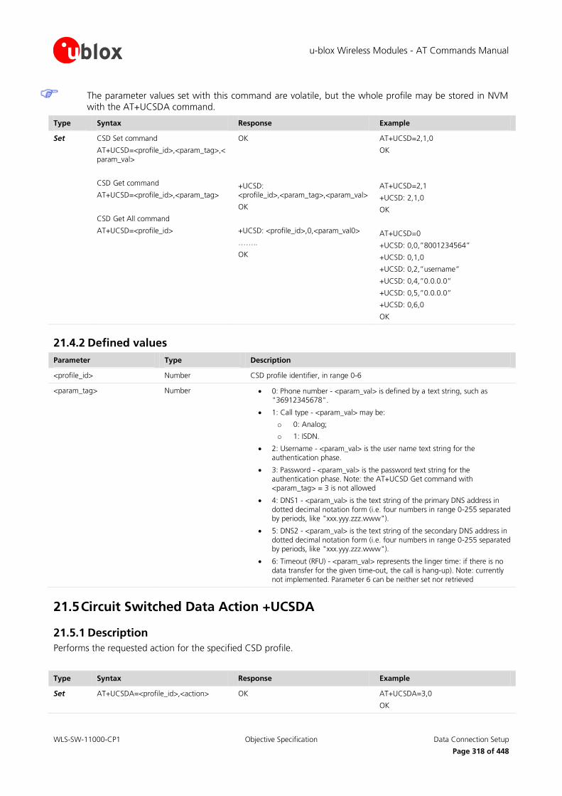
u-blox Wireless Modules - AT Commands Manual
WLS-SW-11000-CP1 Objective Specification Data Connection Setup
Page 318 of 448
The parameter values set with this command are volatile, but the whole profile may be stored in NVM with the AT+UCSDA command.
Type Syntax Response Example
Set CSD Set command
AT+UCSD=<profile_id>,<param_tag>,<param_val>
CSD Get command
AT+UCSD=<profile_id>,<param_tag>
CSD Get All command
AT+UCSD=<profile_id>
OK
+UCSD: <profile_id>,<param_tag>,<param_val>
OK
+UCSD: <profile_id>,0,<param_val0>
……..
OK
AT+UCSD=2,1,0
OK
AT+UCSD=2,1
+UCSD: 2,1,0
OK
AT+UCSD=0
+UCSD: 0,0,”8001234564”
+UCSD: 0,1,0
+UCSD: 0,2,”username”
+UCSD: 0,4,”0.0.0.0”
+UCSD: 0,5,”0.0.0.0”
+UCSD: 0,6,0
OK
21.4.2 Defined values
Parameter Type Description
<profile_id> Number CSD profile identifier, in range 0-6
<param_tag> Number 0: Phone number - <param_val> is defined by a text string, such as "36912345678".
1: Call type - <param_val> may be:
o 0: Analog;
o 1: ISDN.
2: Username - <param_val> is the user name text string for the authentication phase.
3: Password - <param_val> is the password text string for the authentication phase. Note: the AT+UCSD Get command with <param_tag> = 3 is not allowed
4: DNS1 - <param_val> is the text string of the primary DNS address in dotted decimal notation form (i.e. four numbers in range 0-255 separated by periods, like "xxx.yyy.zzz.www").
5: DNS2 - <param_val> is the text string of the secondary DNS address in dotted decimal notation form (i.e. four numbers in range 0-255 separated by periods, like "xxx.yyy.zzz.www").
6: Timeout (RFU) - <param_val> represents the linger time: if there is no data transfer for the given time-out, the call is hang-up). Note: currently not implemented. Parameter 6 can be neither set nor retrieved
21.5 Circuit Switched Data Action +UCSDA
21.5.1 Description
Performs the requested action for the specified CSD profile.
Type Syntax Response Example
Set AT+UCSDA=<profile_id>,<action> OK AT+UCSDA=3,0
OK

u-blox Wireless Modules - AT Commands Manual
WLS-SW-11000-CP1 Objective Specification Data Connection Setup
Page 319 of 448
Type Syntax Response Example
URC +UUCSDD: <profile_id>
21.5.2 Defined values
Parameter Type Description
<profile_id> Number CSD profile identifier, in range 0-6
<action> Number 0: Reset: clears the specified profile, resetting all parameters to their factory-programmed values
1: Store: saves all parameters of the specified profile in NVM for future retrieval
2: Load: reads all parameters of the specified profile from NVM
3: Activate: performs end-to-end connection establishment for the specified CSD profile, using its pre-defined parameters (i.e. service provider number)
4: Deactivate: releases the GSM data call associated with the specified CSD profile
Only one profile at a time can be associated with an active GSM call.
in case of remote disconnection of a GSM call associated to a CSD profile, the URC is sent to the TE to
inform the user, otherwise the user is in charge of connection release after usage.
21.6 Circuit Switched Network-assigned Data +UCSND
21.6.1 Description
Returns the current (dynamic) network-assigned value of the specified parameter of the active GSM data call
associated with the specified CSD profile.
Type Syntax Response Example
Set AT+UCSND=<profile_id>,<param_tag> +UCSND: <profile_id>,<param_tag>,<dynamic_param_val>
OK
AT+UCSND=2,0
+UCSND: 2,0,"151.9.78.170"
OK
21.6.2 Defined values
Parameter Type Description
<profile_id> Number CSD profile identifier, in range 0-6
<param_tag> Number 0: IP address: dynamic IP address assigned during context activation
1: DNS1: dynamic primary DNS address
2: DNS2: dynamic secondary DNS address
<dynamic_param_val> String Value of the specified <param_tag>

u-blox Wireless Modules - AT Commands Manual
WLS-SW-11000-CP1 Objective Specification DNS
Page 320 of 448
22 DNS DNS service requires the user to define and activate a connection profile, either PSD or CSD, using the specific
AT commands described in chapter “Data Connection Setup AT Commands”.
When this command reports an error which is not a +CME ERROR, the error class and code is provided through
+USOER AT command (more details in chapter 23.6).
22.1 Resolve Name / IP Number through DNS +UDNSRN
22.1.1 Description
Translates a domain name to an IP address or an IP address to a domain name by using an available DNS. There
are two available DNSs, primary and secondary. They are usually provided by the network after GPRS activation
or CSD establishment. They are automatically used in the resolution process if available. The resolutor will use first the primary DNS, otherwise if there is no answer, the second DNS will be involved. The user can replace
each network provided DNS by setting its own DNS. In this case the command AT+UPSD should be used for a
PSD context or the AT+UCSD command for the CSD context. If a DNS value different from "0.0.0.0" is provided, the user DNS will replace the correspondent network-provided one. Pay attention to the DNS setting for the
different profiles since the user DNS can be put into action if the corresponding profile is activated (if the user
sets a DNS for a profile, and a different profile is activated, the user DNS has no action and the network DNS is used if available).
Usage of the network provided DNSs is recommended.
Type Syntax Response Example
Set AT+UDNSRN=<resolution_type>,<domain_ip_string>
+UDNSRN: <resolved_ip_address>
OK
or
+UDNSRN: <resolved_domain_name>
OK
AT+UDNSRN=0,"www.google.com"
+UDNSRN: "216.239.59.147"
OK
22.1.2 Defined values
Parameter Type Description
<resolution_type> Number Type of resolution operation
0: domain name to IP address
1: IP address to domain name (host by name)
<domain_ip_string> String Domain name (resolution_type=0) or the IP address in (resolution_type=1) to be resolved
<resolved_ip_address> String Resolved IP address corresponding to the specified domain name
<resolved_domain_name> String Resolved domain name corresponding to the provided IP address

u-blox Wireless Modules - AT Commands Manual
WLS-SW-11000-CP1 Objective Specification TCP/IP UDP/IP
Page 321 of 448
23 TCP/IP UDP/IP
23.1 Introduction
Before using TCP/IP services, a connection profile (either PSD or CSD) must be defined and activated, with AT
commands described in chapter 21 “Data Connection Setup”. The sockets can be managed independently and
simultaneously over the same bearer (either PSD or CSD). AT commands for both reading and writing data on sockets are provided and URC notifies the external application of incoming data and transmission result, no need
for polling.
When these commands report an error which is not a +CME ERROR, the error code can be queried using the
+USOER (more details in chapter 23.6) or +USOCTL (specifying the socket ID and with <param_id>=1, see
chapter 23.15) AT commands.
Some network operators close dynamic NATs after few minutes if there is no activity on the connection (no data transfer in the period). To solve this problem enable the TCP keep alive
options with 1 minute delay (view +USOSO command, paragraph 23.3).
IP dotted notation doesn’t support a leading 0 in an IP address (e.g. IP = 010.128.076.034 is not
supported, 10.128.76.34 is supported).
When both TCP and UDP socket are used at the same time at the maximum throughput (downlink and uplink at the maximum allowed baud rate) it is possible to lose some incoming
UDP packets due to internal buffer limitation. A possible workaround is provided as follows:
o If it is possible, adopt an application layer UDP acknowledge system
o Stop sending TCP packet (and check with the +USOCTL command that the outgoing
buffer is empty) when expecting to receive UDP data
On LEON-G100 / LEON-G200 series the maximum number of sockets that can be managed are 16.
On LISA-U1 / LISA-U2 series the maximum number of sockets that can be managed are 7.
23.2 Create Socket +USOCR
23.2.1 Description
Creates a socket and associates it with the specified protocol (TCP or UDP), returns a number identifying the socket. Such command corresponds to the BSD socket routine. Up to 16 sockets on LEON-G100 / LEON-G200
series and 7 sockets on LISA-U1 / LISA-U2 series can be created. It is possible to specify the local port to bind
within the socket (UDP only) in order to send data from a specific port.
Type Syntax Response Example
Set AT+USOCR=<protocol>[,<local_port>] +USOCR: <socket>
OK
AT+USOCR=17
+USOCR: 2
OK

u-blox Wireless Modules - AT Commands Manual
WLS-SW-11000-CP1 Objective Specification TCP/IP UDP/IP
Page 322 of 448
23.2.2 Defined values
Parameter Type Description
<protocol> Number 6: TCP
17: UDP
<socket> Number Socket identifier to be used for any future operation on that socket
On LEON-G100 / LEON-G200 series the range goes from 0 to 15
On LISA-U1 / LISA-U2 series the range goes from 0 to 6
<local_port> Number Local port to be used while sending data (for UDP sockets only). If <local_port> is specified creating a TCP socket an error will be raised. The range goes from 1 to 65535.
On LISA-U1 / LISA-U2 series the socket creation operation can be performed only after PDP context
activation on one of the defined profiles.
23.3 Set Socket Option +USOSO
23.3.1 Description
Sets the specified standard option (type of service, local address re-use, linger time, time-to-live, etc) for the
specified socket, like the BSD setsockopt routine.
Parameters must be set one by one.
Type Syntax Response Example
Set AT+USOSO=<socket>,<level>,<opt_name>,<opt_val>[,<opt_val2>]
OK AT+USOSO=2,6,1,1
OK
23.3.2 Defined values
Parameter Type Description
<socket> Number Socket identifier
On LEON-G100 / LEON-G200 series the range goes from 0 to 15
On LISA-U1 / LISA-U2 series the range goes from 0 to 6
<level> Number 0: IP Protocol
<opt_name> for IP Protocol level may be:
1: Type of service
<opt_val>: 8 bit mask that represent the flags of IP TOS. For more information refer to RFC 791 [27]Range 0-255. Default value is 0
2: Time-to-live
<opt_val>: unsigned 8 bit value representing the TTL. Range 0-255 (default 255)
6: TCP Protocol
<opt_name> for TCP protocol level may be:
1: No delay option: don’t delay send to coalesce packets;
<opt_val>: Number, enables/disables “no delay” option. 1: enable, 0 (default value): disable
2: Keepalive option: send keepalive probes when idle for

u-blox Wireless Modules - AT Commands Manual
WLS-SW-11000-CP1 Objective Specification TCP/IP UDP/IP
Page 323 of 448
Parameter Type Description
<opt_val> milliseconds; <opt_val>: signed 32 bit Number value representing the milliseconds for “keepalive” option. Range 0-2147483647. Default value 7200000 (2 hours).
65535: Socket
<opt_name> for Socket level options may be:
4: Local address re-use.
<opt_val>: Number, enables/disables “local address re-use” option. 1: enable, 0 (default value): disable
8: Keep connections alive.
<opt_val>: Number, enables/disables “keep connections alive” option. 1: enable, 0 (default value): disable
32: Sending of broadcast messages. <opt_val>: Number enables/disables “sending of broadcast messages”. 1: enable, 0 (default value): disable
128: Linger on close if data present. <opt_val>: Number, sets on/off “linger” option. 1: enable, 0 (default value): disable
<opt_val2>: signed 16 bit Number, linger time, range 0-32767. Default is 0.
512: Local address and port re-use. <opt_val>: Number, enables/disables “local address and port re-use”. 1: enable, 0 (default value): disable
23.4 Get Socket Option +USOGO
23.4.1 Description
Retrieves the specified standard option (type of service, local address re-use, linger time, time-to-live, etc) for the specified socket, like the BSD getsockopt routine.
Type Syntax Response Example
Set AT+USOGO=<socket>,<level>,<opt_name>
+USOGO: <opt_val>[,<opt_val2>]
OK
AT+USOGO=0,0,2 +USOGO: 255
OK
23.4.2 Defined values
Parameter Type Description
<socket> Number Socket identifier
On LEON-G100 / LEON-G200 series the range goes from 0 to 15
On LISA-U1 / LISA-U2 series the range goes from 0 to 6
<level> Number 0: IP Protocol
<opt_name> for IP Protocol level can be:
o 1: Type of service.
o 2: Time-to-live.
6: TCP Protocol
<opt_name> for TCP protocol level may be:
o 1: No delay option: don’t delay send to coalesce packets.
o 2: Keepalive option: send keepalive probes when idle for <opt_val> milliseconds.
65535: Socket

u-blox Wireless Modules - AT Commands Manual
WLS-SW-11000-CP1 Objective Specification TCP/IP UDP/IP
Page 324 of 448
Parameter Type Description
<opt_name> for Socket level options may be:
o 4: Local address re-use.
o 8: Keep connections alive.
o 32: Sending of broadcast messages.
o 128: Linger on close if data present; <opt_val2>: Number, linger time;
o 512: Local address and port re-use.
For values returned by the +USOGO command, refer to +USOSO description (paragraph 23.3.2).
23.5 Close Socket +USOCL
23.5.1 Description
Closes the specified socket, like the BSD close routine. In case of remote socket closure the user is notified via
the URC.
Type Syntax Response Example
Set AT+USOCL=<socket> OK AT+USOCL=2
OK
URC +UUSOCL: <socket> +UUSOCL: 2
23.5.2 Defined values
Parameter Type Description
<socket> Number Socket identifier
On LEON-G100 / LEON-G200 series the range goes from 0 to 15
On LISA-U1 / LISA-U2 series the range goes from 0 to 6
23.6 Get Socket Error +USOER
23.6.1 Description
Retrieves the last error occurred in the last socket operation, stored in the BSD standard variable error.
Type Syntax Response Example
Action AT+USOER +USOER: <socket_error>
OK
+USOER: 104
OK
23.6.2 Defined values
Parameter Tye Description
<socket_error> Number Code of the last error occurred in a socket operation. The allowed values are listed in A.1.4
0: no error

u-blox Wireless Modules - AT Commands Manual
WLS-SW-11000-CP1 Objective Specification TCP/IP UDP/IP
Page 325 of 448
23.7 Connect Socket +USOCO
23.7.1 Description
Establishes a peer-to-peer connection of the socket to the specified remote host on the given remote port, like the BSD connect routine. If the socket is a TCP socket, the command will actually perform the TCP negotiation
(3-way handshake) to open a connection. If the socket is a UDP socket, this function will just declare the remote
host address and port for later use with other socket operations (e.g. +USOWR, +USORD). This is important to note because if <socket> refers to a UDP socket, errors will not be reported prior to an attempt to write or read
data on the socket.
(UDP socket) due to the UDP specific AT commands, this command should be considered obsolete and it
is strongly recommended avoiding its usage while working with UDP sockets. The command’s
functionality for UDP socket is maintained for backward compatibility only, consider to use +USOST and
+USORF command instead of +USOCO with +USOWR and +USORD.
Type Syntax Response Example
Set AT+USOCO=<socket>,<remote_addr>,<remote_port>
OK AT+USOCO=3,"151.63.16.9",1200
OK
23.7.2 Defined values
Parameter Type Description
<socket> Number Socket identifier
On LEON-G100 / LEON-G200 series the range goes from 0 to 15
On LISA-U1 / LISA-U2 series the range goes from 0 to 6
<remote_addr> String Remote host IP address in dotted decimal notation form (i.e. four numbers in range 0-255 separated by periods) or domain name of the remote host
<remote_port> Number Remote host port, in range 1-65535
23.8 Write Socket Data +USOWR
23.8.1 Description
Writes the specified amount of data to the specified socket, like the BSD write routine, and returns the number
of bytes of data actually written. Applied to UDP sockets too, after a +USOCO Connect Socket command.
There are three kinds of syntax:
Base syntax normal: writing simple strings to the socket, there are characters which are forbidden
Base syntax HEX: writing hexadecimal strings to the socket, the string will be converted in binary data and sent to the socket
Binary extended syntax: mandatory for writing any character in the ASCII range [0x00, 0xFF]
(about UDP socket): due to the UDP specific AT commands, it is preferred to use the +USOST command
to send data via UDP socket. +USOST command doesn’t require the usage of +USOCO before sending
data.
(about TCP socket): if no network signal is available, TCP packets are enqueued until the network will
become available again. It the TCP queue is full the +USOWR command will return error. To get the last

u-blox Wireless Modules - AT Commands Manual
WLS-SW-11000-CP1 Objective Specification TCP/IP UDP/IP
Page 326 of 448
socket error use the +USOCTL command with param_id 1 (see +USOCTL command description). If the error returned is 11, it means that the queue is full.
(about UDP socket): if no network signal is available, out going UDP packet may be lost.
The URC indicates that data has been sent to lower level of protocol stack. This is not an indication of an
acknowledgment received by the remote server the socket is connected to.
The base syntax HEX mode is not available on LEON-G100-05S / LEON-G200-05S and previous versions
or on LISA-U1x0-00S versions.
To enable the base syntax HEX mode, refer to the AT+UDCONF command description (chapter 17.19).
Type Syntax Response Example
Set
(Base)
AT+USOWR=<socket>,<length>,<data> +USOWR: <socket>,<length>
OK
AT+USOWR=3,12,"Hello world!"
+USOWR: 3,12
OK
Set
(Binary)
AT+USOWR=<socket>,<length>
After the”@” prompt <length> bytes of data are entered
@
+USOWR: <socket>,<length>
OK
AT+USOWR=3,16
@16 bytes of data
+USOWR: 3,16
OK
(about TCP socket): if the connection is closed by the remote host the +UUSOCL indication is not sent
until all received data is read using the AT+USORD command. If AT+USOWR command is used in this
situation, it returns +USOWR: <socket>,0<CR><LF>OK.
23.8.2 Defined values
Parameter Type Description
<socket> Number Socket identifier
On LEON-G100 / LEON-G200 series the range goes from 0 to 15
On LISA-U1 / LISA-U2 series the range goes from 0 to 6
<length> Number Number of data bytes to write:
Base syntax normal mode: range 0-512 (on LISA-U1 series the range goes from 0 to 1024)
Base syntax HEX mode: range 0-250
Binary extended syntax: range 0-1024
<data> String Data bytes to be written. Note that not all of the ASCII charset can be used
For Base Syntax:
o Allowed ASCII characters: 0x20 (space), 0x21 and from 0x23 to 0xFF, all the alphanumeric set,
symbols and extended ASCII charset from 0x80 to 0xFF
o Forbidden: The control characters from 0x00 to 0x1F (included), 0x22 character, quotation
marks (")
o The value of <length> and the actual length of <data> must match
o For base syntax HEX mode, only ASCII characters 0-9, A-F and a-f are allowed. The length of
the <data> parameter must be two times the <length> parameter
For Binary Syntax:

u-blox Wireless Modules - AT Commands Manual
WLS-SW-11000-CP1 Objective Specification TCP/IP UDP/IP
Page 327 of 448
o After the command is sent, the user waits for the @ prompt. When it appears the stream of bytes can be provided. After the specified amount of bytes has been sent, the system returns
with OK (or ERROR). The feed process cannot be interrupted i.e. the return in the command
mode can be effective only when the number of bytes provided is the declared one
o The binary extended syntax is the only way for the system to accept control characters as data;
for the AT command specifications 3GPP TS 27.005 [16], characters like <CR>, <CTRL-Z>,
quotation marks, etc. have a specific meaning and they cannot be used like data in the command itself. The command is so extended with a specific acceptance state identified by the
@ prompt
o This feature can be successfully used when there is need to send a byte stream which belongs to a protocol that has any kind of characters in the ASCII range [0x00,0xFF]
o In binary mode LISA-U1 / LISA-U2 series doesn’t display the echo of data bytes
o In binary mode LEON-G100 / LEON-G200 displays the echo of data bytes
o Binary syntax is not affected by HEX mode option
For <data> parameter not all of the ASCII charset can be used.
23.9 Send To command +USOST (UDP only)
23.9.1 Description
Writes the specified amount of data to the remote address, like the BSD sendto routine, and returns the number of bytes of data actually written. It can be applied to UDP sockets only. This command allows the reuse of the
same socket to send data to many different remote hosts.
There are three kinds of syntax:
Base syntax normal: writing simple strings to the socket, there are characters which are forbidden
Base syntax HEX: writing hexadecimal strings to the socket, the string will be converted in binary data and sent to the socket
Binary extended syntax: mandatory for writing any character in the ASCII range [0x00, 0xFF]
It is strongly recommended using this command to send data while using UDP sockets. It is also
recommended avoiding +USOCO usage with UDP socket.
(about UDP socket): if no network signal is available, out coming UDP packet may be lost.
The base syntax HEX mode is not available on LEON-G100-05S / LEON-G200-05S and previous versions
or on LISA-U1x0-00S versions.
To enable the base syntax HEX mode, refer to the AT+UDCONF command description (chapter 17.19).
Type Syntax Response Example
Set
(Base)
AT+USOST=<socket>,<remote_ip_address>,<remote_port>,<length>,<data>
+USOST: <socket>,<length>
OK
AT+USOST=3,"151.9.34.66",449,16,"16 bytes of data"
+USOST: 3,16
OK
Set
(Binary)
AT+USOST=<socket>,<remote_ip_address>,<remote_port>,<length>
After the”@” prompt <length> bytes of data are entered
@
+USOST: <socket>,<length>
OK
AT+USOST=3,"151.9.34.66",449,16
@16 bytes of data
+USOST: 3,16
OK

u-blox Wireless Modules - AT Commands Manual
WLS-SW-11000-CP1 Objective Specification TCP/IP UDP/IP
Page 328 of 448
23.9.2 Defined values
Parameter Type Description
<socket> Number Socket identifier
On LEON-G100 / LEON-G200 series the range goes from 0 to 15
On LISA-U1 / LISA-U2 series the range goes from 0 to 6
<remote_ip_address> String Remote host IP address
<remote_port> Number Remote host port
<length> Number Number of data bytes to write
Base syntax normal mode: range 0-512 (on LISA-U1 series the range goes from 0 to 1024)
Base syntax HEX mode: range 0-250
Binary syntax mode: range 0-1024
<data> String Data bytes to be written (note that not all of the ASCII charset can be used)
For Base Syntax:
o Allowed ASCII characters: 0x20 (space), 0x21 and from 0x23 to 0xFF. Substantially all of the
alphanumeric set, symbols and extended ASCII charset from 0x80 to 0xFF
o Forbidden: The control characters from 0x00 to 0x1F (included), 0x22 character, quotation marks (")
o The value of <length> and the actual length of <data> must match
o For base syntax HEX mode, only ASCII characters 0-9, A-F and a-f are allowed. The length of the <data> parameter must be two times the <length> parameter
For Binary Syntax:
o After the command is sent, the user waits for the @ prompt. When it appears the stream of
bytes can be provided. After the specified amount of bytes has been sent, the system returns with OK (or ERROR). The feed process cannot be interrupted i.e. the return in the command
mode can be effective only when the number of bytes provided is the declared one
o That binary extended syntax is the only way for the system to accept control characters as data; for the AT command specifications [16], characters like <CR>, <CTRL-Z>, quotation marks, etc.
have a specific meaning and they cannot be used like data in the command itself. The
command is so extended with a specific acceptance state identified by the @ prompt
o This feature can be successfully used when there is need to send a byte stream which belongs
to a protocol that has any kind of characters in the ASCII range [0x00,0xFF]
o In binary mode LISA-U1 / LISA-U2 series doesn’t display the echo of data bytes
o In binary mode LEON-G100 / LEON-G200 displays the echo of data bytes
o Binary syntax is not affected by HEX mode option
23.10 Read Socket Data +USORD
23.10.1 Description
Reads the specified amount of data from the specified socket, like the BSD read routine. This command can be
used to know the total amount of unread data.
For the TCP socket type the URC +UUSORD: <socket>,<length> notifies the data bytes available for reading, either when buffer is empty and new data arrives or after a partial read by the user.

u-blox Wireless Modules - AT Commands Manual
WLS-SW-11000-CP1 Objective Specification TCP/IP UDP/IP
Page 329 of 448
For the UDP socket type the URC +UUSORD: <socket>,<length> notifies that a UDP packet has been received, either when buffer is empty or after a UDP packet has been read and one or more packets are stored in the
buffer.
In case of a partial read of a UDP packet +UUSORD: <socket>,<length> will show the remaining number of data bytes of the packet the user is reading.
(about UDP socket) Due to the UDP specific AT command, it is preferred to use the +USORF command
to read data from UDP socket. +USORF command doesn’t require the usage of +USOCO before reading data.
When applied to UDP active sockets if the UDP socket is not set in listening mode (see +USOLI) it won’t
be possible to receive any packet if a previous write operation is not performed.
If the HEX mode is enabled (refer to +UDCONF command, chapter 17.19) the received data will be displayed using an hexadecimal string.
The base syntax HEX mode is not available on LEON-G100-05S / LEON-G200-05S and previous versions
or on LISA-U1x0-00S versions.
Type Syntax Response Example
Set AT+USORD=<socket>,<length> +USORD: <socket>,<length>,<data in the ASCII [0x00,0xFF] range>
OK
AT+USORD=3,16
+USORD: 3,16,"16 bytes of data"
OK
URC +UUSORD: <socket>,<length> +UUSORD: 3,16
23.10.2 Defined values
Parameter Type Description
<socket> Number Socket identifier
On LEON-G100 / LEON-G200 series the range goes from 0 to 15
On LISA-U1 / LISA-U2 series the range goes from 0 to 6
<length> Number Number of data bytes
to read stored in buffer, in range 0-1024 in the set command
read from buffer, in range 0-1024
stored in buffer for the URC
<data> String Data bytes to be read
The returned data may be any ASCII character in the range [0x00,0xFF] i.e. control characters. The
starting quotation marks shall not be taken into account like data; the first byte of data starts after the first quotation marks. Then the other characters are provided for a <length> amount. An application
should rely on the <length> info to count the received number of characters (after the starting
quotation marks) especially if any protocol control characters are expected.
If an application deals with letter and number characters only i.e. all of the expected characters are
outside the [0x00, 0x1F] range and are not quotation marks, the AT+USORD response quotation marks
can be assumed to identify the start and the end of the received data packet. Always check <length> to
identify the valid data stream.
If the number of data bytes requested to be read from the buffer is bigger than the number of bytes
stored in the buffer only the available amount of data bytes will be read.
When <length>= 0, the command returns the total amount of data present in the network buffer.
If the HEX mode is enabled, the length of <data> will be 2 times <length>.

u-blox Wireless Modules - AT Commands Manual
WLS-SW-11000-CP1 Objective Specification TCP/IP UDP/IP
Page 330 of 448
Example: 23 unread bytes in the socket
AT+USORD=3,0
+USORD: 3,23
OK
23.11 Receive From command +USORF (UDP only)
23.11.1 Description
Reads the specified amount of data from the specified UDP socket, like the BSD recvfrom routine. The URC
+UUSORF: <socket>,<length> (or also +UUSORD: <socket>,<length>) notifies that new data is available for reading, either when new data arrives or after a partial read by the user for the socket. This command can also
return the total amount of unread data.
This command can be applied to UDP sockets only, and it can be used to read data after both +UUSORD and +UUSORF unsolicited indication.
It is strongly recommended using this command to read data while using UDP sockets. It is also
recommended avoiding +USOCO usage with UDP socket.
If the HEX mode is enabled (see AT+UDCONF) the received data will be displayed using an hexadecimal string.
The base syntax HEX mode is not available on LEON-G100-05S / LEON-G200-05S and previous versions
or on LISA-U1x0-00S versions.
Type Syntax Response Example
Set AT+USORF=<socket>,<length> +UUSORF: <socket>,<length>
+USORF: <socket>,<remote_ip_addr>,<remote_port>,<length>,<data in the ASCII [0x00,0xFF] range>
OK
+UUSORF: 3,16
AT+USORF=3,16
+USORF: 3,"151.9.34.66",2222,16,"16 bytes of data"
OK
URC +UUSORF: <socket>,<length> +UUSORF: 3,16
23.11.2 Defined values
Parameter Type Description
<socket> Number Socket identifier
On LEON-G100 / LEON-G200 series the range goes from 0 to 15
On LISA-U1 / LISA-U2 series the range goes from 0 to 6
<remote_ip_address> String Remote host IP address
<remote_port> Number Remote host port
<length> Number Number of data bytes to read, in range 0-1024
<data> String Data bytes to be read
Each packet received from the network is stored in a separate buffer and the command is capable to
read only a packet (or e portion of it) at time. This means that if <length> is greater than the packet size, the command will return a maximum amount of data equal to the packet size, also if there are other
packets in the buffer. The remaining data (i.e. the remaining UDP packets) can be read with further
reads.

u-blox Wireless Modules - AT Commands Manual
WLS-SW-11000-CP1 Objective Specification TCP/IP UDP/IP
Page 331 of 448
The returned data may have any kind of ASCII character in the range [0x00,0xFF] i.e. control characters too. The starting quotation marks shall not be taken into account like data; the first byte of data starts
after the first quotation marks. Then the other characters are provided for a <length> amount. At the
end of the length byte stream, another quotation marks followed by <CR><LF> are provided for user convenience and visualization purposes. An application should rely on the <length> info to count the
received number of characters (after the starting quotation marks) especially if any protocol control
characters are expected.
If an application deals with letter and number characters only i.e. all of the expected characters are
outside the [0x00, 0x1F] range and are not quotation marks, the AT+USORD response quotation marks
can be assumed to identify the start and the end of the received data packet, anyway the <length> field
usage to identify the valid data stream is recommended.
When <length>= 0, the command returns the total amount of data present in the network buffer.
If the HEX mode is enabled, the length of <data> will be 2 times <length>.
Example: 23 unread bytes in the socket
AT+USORF=3,0
+USORF: 3,23
OK
23.12 Set Listening Socket +USOLI
23.12.1 Description
Sets the specified socket in listening mode on the specified port of service, waiting for incoming connections (TCP) or data (UDP).
For TCP sockets, incoming connections will be automatically accepted and notified via the URC
+UUSOLI: <socket>,<ip_address>,<port>,<listening_socket>,<local_ip_address>,<listening_port>, carrying the connected socket identifier, the remote IP address and port.
For UDP sockets, incoming data will be notified via URC +UUSORF: <listening_socket>,<length>. To know
from which remote IP address and port the data is coming from, use the AT+USORF command.
Type Syntax Response Example
Set AT+USOLI=<socket>,<port> OK (TCP)
AT+USOLI=2,1200
OK
+UUSOLI: 3,"151.63.16.7",1403,2,"82.89.67.164",1200
(UDP)
AT+USOLI=0,1182
OK
+UUSORF: 0,1024
URC (TCP)
+UUSOLI: <socket>,<ip_address>,<port>,<listening_socket>,<local_ip_address>,<listening_port>
+UUSOLI: 3,"151.63.16.7",1403,0,"82.89.67.164",200
URC (UDP)
+UUSORF: <listening_socket>,<len> +UUSORF: 1,967

u-blox Wireless Modules - AT Commands Manual
WLS-SW-11000-CP1 Objective Specification TCP/IP UDP/IP
Page 332 of 448
23.12.2 Defined values
Parameter Type Description
<socket> Number Socket identifier
On LEON-G100 / LEON-G200 series the range goes from 0 to 15
On LISA-U1 / LISA-U2 series the range goes from 0 to 6
<port> Number Port of service, range 1-65535. Port numbers below 1024 are not recommended since they are usually reserved
<ip_address> String Remote host IP address (only in URC +UUSOLI)
<listening_socket> Number Socket identifier specified within the AT+USOLI command, indicates on which listening socket the connection has been accepted (only in +UUSOLI URC)
<local_ip_address> String TE IP address (only in +UUSOLI URC)
<listening_port> Number Listening port that has accepted the connection. This port is specified within the AT+USOLI command (only in +UUSOLI URC)
<length> Number Data length received on the UDP listening socket (only in +UUSORF unsolicited indication). In order to know the sender IP address and port, use the +USORF command.
In case of notification via the URC +UUSOLI <port> is intended as the remote port.
23.13 Firewall control +UFRW
23.13.1 Description
Enables/disables internal firewall and controls filtering settings (i.e. define IP white list). When enabled, IP connections are accepted only if the IP address belongs to the defined IP white list.
Firewall applies for incoming connections only (i.e. listening sockets set by means of +USOLI command).
Type Syntax Response Example
Set AT+UFRW=<action>[,<white_ip_addr_mask>]
OK AT+UFRW=0
OK
Read AT+UFRW? +UFRW: <firewall_status>[,<white_ip_addr_mask1>[,<white_ip_addr_mask2>[,…]]]
OK
Test AT+UFRW=? +UFRW: (list of supported <action>s)
OK
+UFRW: (0-4)
OK

u-blox Wireless Modules - AT Commands Manual
WLS-SW-11000-CP1 Objective Specification TCP/IP UDP/IP
Page 333 of 448
23.13.2 Defined values
Parameter Type Description
<action> Number 0: disable internal firewall. The parameter <white_ip_addr_mask> is not allowed in this case: if present error message will be returned
1: enable internal firewall. The parameter <white_ip_addr_mask> is not allowed in this case: if present error message will be returned
2: add specified IP address mask to firewall white list. The parameter <white_ip_addr_mask> is mandatory. The maximum size of firewall white list is 10 IP address masks: up to 10 different IP address masks can be added to firewall white list.
3: remove specified IP address mask from firewall white list. The parameter <white_ip_addr_mask> is mandatory
4: clear firewall white list. The parameter <white_ip_addr_mask> is not allowed in this case: if present error message will be returned
<white_ip_addr_mask> String White IP address mask to be applied to remote end IP address to decide if to accept or not the remote connection. The IP address mask is made up of 4 bytes of information expressed as four numbers in range 0-255 separated by periods (e.g. "xxx.yyy.zzz.www"). An incoming connection attempt from the remote end IP address <incoming_ip_addr> is accepted if matching the following criterium for at least one of the IP address masks in the firewall white list: <incoming_ip_addr> & <white_ip_addr_mask> == <incoming_ip_addr>
<firewall_status> Number 0: disabled
1: enabled
23.14 Set socket in Direct Link mode +USODL
23.14.1 Description
This command establishes a transparent end to end communication with an already connected TCP or UDP socket via the serial interface. Data can be sent to the socket and can be received via the serial port: the usage of
HW handshake is recommended.
The transparent TCP/UDP connection mode can be exited via +++ sequence, entered after at least 2 s of suspension of transmission to the port. The socket will remain connected and communication can be
re-established anytime.
UDP Direct Link is not available on LEON-G100/LEON-G200 series and LISA-U1x0-00S versions.
Type Syntax Response Example
Set AT+USODL=<socket> CONNECT AT+USODL=3
CONNECT
23.14.2 Defined values
Parameter Type Description
<socket> Number Socket identifier
On LEON-G100 / LEON-G200 series the range goes from 0 to 15
On LISA-U1 / LISA-U2 series the range goes from 0 to 6

u-blox Wireless Modules - AT Commands Manual
WLS-SW-11000-CP1 Objective Specification TCP/IP UDP/IP
Page 334 of 448
Direct Link mode won’t be available for TCP application protocols (HTTP, SMTP). This is because application protocols require a server request formatting and a response evaluation, but in direct link
connection this feature is not yet available.
On LISA-U1 series, during a 3G connection on UART interface, the data rate must be at least 115200
b/s.
23.15 Socket Control +USOCTL
23.15.1 Description
Allows interaction with the low level socket layer.
Type Syntax Response Example
Set AT+USOCTL=<socket>,<param_id> +USOCTL: <socket>,<param_id>,<param_val>[,<param_val2>]
OK
AT+USOCTL=0,2
+USOCTL: 0,2,38
OK
23.15.2 Defined values
Parameter Type Description
<socket> Number Socket identifier
On LEON-G100 / LEON-G200 series the range goes from 0 to 15
On LISA-U1 / LISA-U2 series the range goes from 0 to 6
<param_id> Number Control request identifier. Possible values are:
0: query for socket type
1: query for last socket error
2: get the total amount of bytes sent from the socket
3: get the total amount of bytes received by the socket
4: query for remote peer IP address and port
10: query for TCP socket status (only TCP sockets)
11: query for TCP outgoing unacknowledged data (only TCP sockets)
5-9, 12-99: RFU
<param_val> Number / String This value may assume different means depending of <param_id>.
If <param_id> is 0, <param_val> can assume these values:
6 TCP socket
17: UDP socket
If <param_id> is 1, <param_val> can assume these values:
N: last socket error
If <param_id> is 2, <param_val> can assume these values:
N: the total amount (in bytes) of sent (acknowledged + unacknowledged) data
If <param_id> is 3, <param_val> can assume these values:
N: the total amount (in bytes) of received (read) data
If <param_id> is 4, <param_val> can assume these values:
A string representing the remote peer IP address expressed in dotted decimal form
If <param_id> is 10, <param_val> can assume these values:
0: the socket is in INACTIVE status

u-blox Wireless Modules - AT Commands Manual
WLS-SW-11000-CP1 Objective Specification TCP/IP UDP/IP
Page 335 of 448
Parameter Type Description
1: the socket is in LISTEN status
2: the socket is in SYN_SENT status
3: the socket is in SYN_RCVD status
4: the socket is in ESTABILISHED status
5: the socket is in FIN_WAIT_1 status
6: the socket is in FIN_WAIT_2 status
7: the sokcet is in CLOSE_WAIT status
8: the socket is in CLOSING status
9: the socket is in LAST_ACK status
10: the socket is in TIME_WAIT status
If <param_id> is 11, <param_val> can assume these values:
N: the total amount of outgoing unacknowledged data
<param_val2> Number This value is present only when <param_id> is 4. It represents the remote peer IP port.

u-blox Wireless Modules - AT Commands Manual
WLS-SW-11000-CP1 Objective Specification FTP
Page 336 of 448
24 FTP Proprietary u-blox AT commands. FTP AT commands set can be used for sending and receiving files over the
available bearer, transparently retrieving and storing them in the file system. Standard file and directory management operations on the remote FTP server are as well possible. PSD or CSD connection must be
established before using FTP client services (AT commands for establishing connection are described in chapter
21 “Data Connection Setup AT Commands”).
Basically, two AT commands are necessary for an FTP client service: one AT command to configure the FTP
profile, a second AT command to execute a specific FTP command. The final result of an FTP execute command
will be notified through the URC +UUFTPCR whereas data will be provided through URC +UUFTPCD.
When these commands report an error which is not a +CME ERROR, the error code can be queried using the
+UFTPER AT command (more details in chapter 24.5).
24.1 FTP Control +UFTP
24.1.1 Description
Sets up a parameter for FTP service, or resets a parameter to its factory-programmed value. Set/reset command
needs to be executed for each single <param_tag>. Read command returns the current setting of all the FTP
parameters, one per line (i.e. the FTP profile). The FTP parameter values set with this command are all volatile (not stored in non-volatile memory)
Not available on LISA-U1x0-00S versions.
Type Syntax Response Example
Set Set command
AT+UFTP=<param_tag>,<param_val>
Reset command
AT+UFTP=<param_tag>
OK
OK
AT+UFTP=7,21
OK
Read AT+UFTP? +UFTP: 0,<param_val0>
+UFTP: 1,<param_val1>
…
OK
+UFTP: 0,"216.239.59.147"
+UFTP: 1,""
+UFTP: 2,"username"
+UFTP: 4,"account"
+UFTP: 5,0
+UFTP: 6,0
+UFTP: 7,21
+UFTP: 8,0
OK
Test AT+UFTP=? +UFTP: (list of supported <param_tag>s)
OK
+UFTP: (0-8)
OK
24.1.2 Defined values
Parameter Type Description
<param_val> Number / String Type and supported content depend on related <param_tag> (details are given here below). If <param_val> is not specified the value of the corresponding parameter <param_tag> is reset to default value

u-blox Wireless Modules - AT Commands Manual
WLS-SW-11000-CP1 Objective Specification FTP
Page 337 of 448
Parameter Type Description
<param_tag> Number 0: FTP server IP address;
<param_val> is the text string of FTP server IP address in dotted decimal notation form (e.g. 111.222.333.444)
1: FTP server name
<param_val> is the text sting of FTP server name (e.g. "ftp.server.com") Maximal length 128 characters
2: Username
<param_val> is the user name text string (maximum 30 characters) for the FTP login procedure
3: Password
<param_val> is the password text string (maximum 30 characters) for the FTP login procedure
4: Account
<param_val> is the additional user account text string (maximum 30 characters) if required for the FTP login procedure
5: Inactivity timeout; <param_val> is the inactivity timeout period in seconds, from 0 to 86400 s. 0 means no timeout (the FTP session will not be terminated in the absence of incoming traffic). The default value is 30 s
6: FTP mode
<param_val> selects the FTP mode:
o 0 (default value): Active
o 1: Passive
7: FTP server port
<param_val> is the remote FTP server listening port, it must be a valid TCP port value:
o Numeric value between 1 and 65535: default value is 21
8: FTP Secure option in explicit mode (SSL encryption of FTP control channel; FTP data channel is not encrypted)
<param_val> selects the Secure option (explicit mode) of FTP client service:
o 0 (default value): No SSL encryption
o 1: Enable SSL encryption of FTP control connection
The response to the read command doesn’t display the <param_tag>=3 (password).
<param_tag>=8 is not available on LEON-G100/LEON-G200 series.
<param_tag>=0 and <param_tag>=1 are mutually exclusive. If value for <param_tag>=0 is specified by
user, then value for <param_tag>=1 is reset or vice versa.
Some network operators do not allow incoming connections. Due to these limitations introduced by
network operators it is possible to encounter problems using FTP active mode. If the FTP active mode fails to exchange files, try the passive mode to solve the problem.
Some network operators do not allow FTPS. In this case the +UFTPC=1 command (FTP login) will return
a failure response via +UUFTPCR URC after an SSL timeout of 30 s.
On LISA-U1 / LISA-U2 series during connection to FTP remote server (via FTP login command) the FTP profile parameters cannot be changed or reset to factory-programmed values until disconnection takes
place (FTP logout). Only <param_tag>=5 (inactivity timeout), and <param_tag>=6 (FTP mode), can be
updated while FTP connection is on the go.

u-blox Wireless Modules - AT Commands Manual
WLS-SW-11000-CP1 Objective Specification FTP
Page 338 of 448
24.2 FTP Command +UFTPC
24.2.1 Description
Triggers the FTP actions corresponding to <ftp_command> parameter. The response indicates if sending the command request to FTP process was successful or not. Final result of FTP action will be returned to the user via
the URC +UUFTPCR (refer to paragraph 24.4 for the command description). As well, when data is requested by
user (e.g. file or directory lists), the information is notified after reception from the FTP server via the URC +UUFTPCD (refer to paragraph 24.3.1 for the command description).
Not available on LISA-U1x0-00S versions.
On LISA-U1 / LISA-U2 series, if SSL option is enabled and network operator does not allow FTPS, the
command failure will be notified via the URC +UUFTPCR after an SSL timeout of 30 s.
Type Syntax Response Example
Set AT+UFTPC=<ftp_command>[,<param1>[,<param2>]]
OK AT+UFTPC=4,"data.zip","data.zip"
OK
Test AT+UFTPC=? +UFTPC: (list of supported <ftp_command>s)
OK
+UFTPC: (0-5,8,10,11,13,14)
OK
24.2.2 Defined values
Parameter Type Description
<param1> String Content depend on related <ftp_command> (details are given below)
<param2> String Content depend on related <ftp_command> (details are given below)
<ftp_command> Number 0: FTP logout; terminates the FTP session by performing a logout. Notice that this AT command just sends a command request to the FTP process. The final FTP result will be notified via the URC +UUFTPCR (refer to chapter 24.4)
o <param1>, <param2> are not allowed (do not give any value)
1: FTP login; connects to the FTP server using the parameters of current FTP profile (set via AT+UFTP command). Notice that this AT command just sends a command request to the FTP process. The final FTP result will be notified via the URC +UUFTPCR (refer to chapter 24.4)
o <param1>, <param2> are not allowed (do not give any value).
2: Delete file from the FTP server. This AT command just sends a command request to the FTP process. The final FTP result will be notified via the URC +UUFTPCR (refer to chapter 24.4)
o <param1> mandatory parameter; text string of the file name to be deleted from FTP host.
o <param2> parameter is not allowed (do not give any value).
3: Rename file. This AT command just sends requests to the FTP process. The final FTP result will be notified via the URC +UUFTPCR (see chapter 24.4).
o <param1> mandatory parameter; text string of the old file name on the FTP host, to be renamed. For the limit of the length of the string, refer to chapter 1.1.3
o <param2> mandatory parameter; text string of the new file name. For the limit of the length of the string, refer to 1.1.3.
4: Retrieve file from the FTP server. This command just sends a command request to the FTP process. The final FTP command result is notified via the URC +UUFTPCR (see 24.4).
o <param1> mandatory parameter; is the remote file name text

u-blox Wireless Modules - AT Commands Manual
WLS-SW-11000-CP1 Objective Specification FTP
Page 339 of 448
Parameter Type Description
string to be retrieved from FTP host.
o <param2> mandatory parameter; is the local file name (module file system) text string to be stored on file system. For the limit of the length of the string, refer to chapter 1.1.3.
5: Store file on the FTP server. This AT command just sends a command request to the FTP process. The final result will be notified via the URC +UUFTPCR (refer to chapter 24.4).
o <param1> mandatory parameter; is the local file name (module file system) text string to be sent from file system. For the limit of the length of the string, refer to chapter 1.1.3.
o <param2> mandatory parameter; is the remote file name to be stored on the FTP server. For the limit of the length of the string, refer to chapter 1.1.3.
6: Retrieve a file from FTP server using direct link mode. This command handles the initial steps of FTP protocol for retrieving a file; after that it will establish a transparent end to end communication with the data connection TCP socket via the serial interface. After the CONNECT message, the file content will be sent directly to the serial interface. The user must switch off the direct link mode (sending +++ to the serial interface) when the data stream is finished. This operation may take up to 10 s because of the command also handles the final steps of FTP
protocol. The final FTP command result is notified via the URC
+UUFTPCR (see 24.4).
o <param1> mandatory parameter; is the remote file name to be retrieved from the FTP server;
7: Send a file to FTP server using direct link mode. This command handles the initial steps of FTP protocol for sending a file; after that it will establish a transparent end to end communication with the data connection TCP socket via the serial interface. After the CONNECT message the user can send the file content via serial interface. Once finished, the user must wait at least 2 s before sending the +++ sequence to switch off the direct link mode. This operation may take a few seconds because the command also handles the final steps of FTP
protocol. The final FTP command result is notified via the URC
+UUFTPCR (see 24.4).
o <param1> mandatory parameter; is the remote file name to be stored in the FTP server;
8: Change working directory to the specified one. This AT command just sends requests to the FTP process. The final FTP command result will be notified via the URC +UUFTPCR (refer to paragraph 24.4).
o <param1> mandatory parameter; is the text string of the destination directory name on the FTP host. For the limit of the length of the string, refer to 1.1.3.
o <param2> parameter is not allowed (do not give a value).
9: RFU;
10: Create a directory on the FTP host. This AT command just sends a command request to the FTP process. The final result will be notified via the URC +UUFTPCR (refer to paragraph 24.4).
o <param1> mandatory parameter; text string of the new directory name to be made on FTP server. For the limit of the length of the string, refer to 1.1.3.
o <param2> parameter is not allowed (do not give a value).
11: Remove directory from the remote FTP server. This AT command just sends a command request to the FTP process. The final result will be notified via the URC +UUFTPCR (refer to paragraph 24.4).
o <param1> mandatory parameter; is the string of the existing directory name to be removed. For the limit of the length of the string, refer to 1.1.3.
o <param2> parameter is not allowed (do not give a value).
12: RFU;

u-blox Wireless Modules - AT Commands Manual
WLS-SW-11000-CP1 Objective Specification FTP
Page 340 of 448
Parameter Type Description
13: Information of a file or a directory. Command just sends a command request to the FTP process. Information of specified file or directory from FTP server will be returned via URC +UUFTPCD (refer to paragraph 24.3). The final FTP command result will be notified via the URC +UUFTPCR (refer to paragraph 24.4).
o <param1> optional parameter; text string of the path file/directory name to be listed. If not specified, the current directory list is requested. For the limit of the length of the string, refer to 1.1.3.
o <param2> parameter is not allowed (do not give a value).
14: List file names in a specified directory. Command just sends a command request to the FTP process. List of file names received from FTP server will be returned via URC +UUFTPCD (refer to paragraph 24.3). The final FTP result will be notified via the URC +UUFTPCR (refer to paragraph 24.4).
o <param1> optional parameter; text string of the path (file or directory) to be name listed. If not specified, the list of files names of current working directory is requested. For the limit of the length of the string, refer to 1.1.3.
o <param2> parameter is not allowed (do not give a value).
24.3 FTP Unsolicited Data URC +UUFTPCD
24.3.1 Description
Returns the data received from the remote FTP server in response to a specified <ftp_command> request previously sent via +UFTPC command.
Not available on LISA-U1x0-00S versions.
On LISA-U1 / LISA-U2 series the URC +UUFTPCD is displayed only on the AT terminal that issued the
+UFTPC related command.
Type Syntax Response Example
URC +UUFTPCD: <ftp_command>,<ftp_data_len>,<ftp_data>
+UUFTPCD: 13,16,"16 bytes of data"
24.3.2 Defined values
Parameter Type Description
<ftp_command> Number FTP command as detailed in Defined values paragraph 24.2.2 “File Transfer Protocol Command +UFTPC”.
<ftp_data_len> Number Amount of data in bytes
<ftp_data> String Data available from FTP server in the ASCII [0x00,0xFF] range. The starting quotation mark shall not be taken into account like data, the first byte of data starts after the first quotation mark. Total number of bytes is <ftp_data_len>. At the end of the byte stream, another quotation mark is provided for user convenience and visualization purposes.

u-blox Wireless Modules - AT Commands Manual
WLS-SW-11000-CP1 Objective Specification FTP
Page 341 of 448
24.4 FTP Command Result URC +UUFTPCR
24.4.1 Description
The final result of the operation for an FTP command previously sent with +UFTPC is provided with this URC.
Not available on LISA-U1x0-00S versions.
Type Syntax Response Example
URC +UUFTPCR: <ftp_command>,<ftp_result>
+UUFTPCR: 1,1
24.4.2 Defined values
Parameter Type Description
<ftp_command> Number Same values as above
<ftp_result> Number 0: Fail
1: Success
24.5 FTP Error +UFTPER
24.5.1 Description
This command retrieves the error class and code of the last FTP operation.
Not available on LISA-U1x0-00S versions.
Type Syntax Response Example
Action AT+UFTPER +UFTPER: <error_class>,<error_code>
OK
+UFTPER: 1,1
OK
24.5.2 Defined values
Parameter Type Description
<error_class> Number Value of error class. Values are listed in paragraph A.1
<error_code> Number Value of class-specific error code (reply code if <error_class> is 0). The values are listed in A.1.1

u-blox Wireless Modules - AT Commands Manual
WLS-SW-11000-CP1 Objective Specification HTTP
Page 342 of 448
25 HTTP u-blox proprietary AT commands for HTTP service. The chapter describes the HTTP AT commands set that can be
used for sending requests to a remote HTTP server, receiving the server response and transparently storing it in the file system. Supported methods are: HEAD, GET, DELETE, PUT, POST file and POST data. Data connection
must be activated using u-blox proprietary AT commands described in chapter 21 “Data Connection Setup AT
Commands”.
When these commands report an error which is not a +CME ERROR, the error code can be queried using the
+UHTTPER AT command (more details in chapter 25.4)
If using CellLocate and HTTP commands HTTP profiles in the range 1-3 must be used.
25.1 HTTP Control +UHTTP
25.1.1 Description
Sets up the necessary parameters for HTTP service, or resets them to the factory-programmed values. Up to 4
different HTTP profiles can be defined. To change the settings of a specified HTTP profile set command needs to be executed for each single <param_tag>. The get command returns the current setting of the specified
parameter of HTTP profile, while the reset command resets to factory-programmed values all the parameters of
specified HTTP profile.
Not available on LISA-U1x0-00S versions.
HTTP parameters are not saved in the non volatile memory.
Type Syntax Response Example
Set Set command
AT+UHTTP=<profile_id>,<param_tag>,<param_val>
Get command
AT+UHTTP=<profile_id>,<param_tag>
Reset command
AT+UHTTP=<profile_id>
OK
+UHTTP: <profile_id>,<param_tag>,<param_val>
OK
AT+UHTTP=2,0,"125.24.51.133"
OK
AT+UHTTP=2,0
+UHTTP: 2,0,"125.24.51.133"
OK
AT+UHTTP=2
OK
Test AT+UHTTP=? +UHTTP: (list of supported <profile_id>s),(list of supported <param_tag>s)
OK
+UHTTP: (0-3),(0-6)
OK
25.1.2 Defined values
Parameter Type Description
<profile_id> Number HTTP profile identifier, in range 0-3
<param_val> Number / String Type and supported content depend on related <param_tag> (details below). If <param_val> is not specified, the current parameter value for the

u-blox Wireless Modules - AT Commands Manual
WLS-SW-11000-CP1 Objective Specification HTTP
Page 343 of 448
Parameter Type Description
corresponding <param_tag> is returned.
<param_tag> Number If <param_tag> and <param_val> are not specified, all the parameters of the corresponding HTTP <profile_id> are reset to default value.
0: HTTP server IP address
o <param_val>: text string of HTTP server IP address in dotted decimal notation form (i.e. four numbers in range 0-255 separated by periods)
1: HTTP server name
o <param_val>: text string of HTTP server name (e.g. "http.server.com") Maximum length for string is 128 characters
2: Username
o <param_val>: user name text string (maximum 30 characters) for the HTTP login procedure if authentication is used
3: Password
o <param_val>: password text string (maximum 30 characters) for the HTTP login procedure if authentication is used
4: Authentication type
o <param_val> is the HTTP authentication method (if any)
0 (default value): No authentication
1: Basic authentication
5: HTTP server port
o <param_val> Number type value of the HTTP server port to be used in HTTP request, in range 1-65535. Default value is 80.
6: HTTP Secure option (SSL encryption)
o <param_val> selects the Secure option of HTTP service
0 (default value): No SSL encryption
1: Enable SSL encryption
<param_tag>=0 and <param_tag>=1 are mutually exclusive. If <param_val> value for <param_tag>=0
is specified by user, then value for <param_tag>=1 is reset, or vice versa.
<param_tag>=6 is not supported on LEON-G100 / LEON-G200 / SARA-G350 series.
When HTTP Secure option is enabled, the assigned HTTP port is 443.
25.2 HTTP Command +UHTTPC
25.2.1 Description
Triggers the HTTP action specified in <http_command> parameter, using the HTTP profile settings (previously set
up by AT+UHTTP command), and corresponding to <profile_id>. The response indicates if sending the command
request to HTTP process was successful or not. Final result of HTTP action will be returned to the user via the unsolicited indication +UUHTTPCR (chapter 25.3).
Not available on LISA-U1x0-00S versions.
Type Syntax Response Example
Set AT+UHTTPC=<profile_id>,<http_command>,<param1>,<param2>[,<param3>[,<param4>]]
OK AT+UHTTPC=0,1,"/path/file.html","responseFilename"
OK

u-blox Wireless Modules - AT Commands Manual
WLS-SW-11000-CP1 Objective Specification HTTP
Page 344 of 448
Type Syntax Response Example
Test AT+UHTTPC=? +UHTTPC: (list of supported <profile_id>s),(list of supported <http_command>s)
OK
+UHTTPC: (0-3), (0-5)
OK
25.2.2 Defined values
Parameter Type Description
<profile_id> Number HTTP profile identifier, in range 0-3
<param1> String Path of HTTP server resource. Maximum length 128 characters
<param2> String Filename where the HTTP server response will be stored. If the file already exists, it will be overwritten. If <param2> is the empty string (""), the default "http_last_response_<profile_id>" filename will be used
<param3> String Content depends on related <http_command> (details below).
<param4> Number Content depends on related <http_command> (details below).
<http_command> Number 0: HEAD command; issue an HEAD request to HTTP server. Command just sends a command request to the HTTP process. The final HTTP command result will be notified via the URC +UUHTTPCR (see detailed description)
o <param3>: not allowed
o <param4>: not allowed
1: GET command; perform a GET request to HTTP server. Command just sends a command request to the HTTP process. The final HTTP command result will be notified via the URC +UUHTTPCR (see details below)
o <param3>: not allowed
o <param4>: not allowed
2: DELETE command; send a DELETE request to HTTP server. Command just sends a command request to the HTTP process. The final HTTP command result will be notified via the URC +UUHTTPCR (see detailed description)
o <param3>: not allowed
o <param4>: not allowed
3: PUT command; perform a PUT request to HTTP server. Command just sends a command request to the HTTP process. The final HTTP command result will be notified via the URC +UUHTTPCR (see detailed description)
o <param3>: mandatory parameter; text string of the file system filename to be sent to the HTTP server within the PUT request
o <param4>: not allowed
4: POST a file command; issue a POST request for sending a file to the HTTP server. Command just sends a command request to the HTTP process. The final HTTP command result will be notified via the URC +UUHTTPCR (see detailed description).
o <param3>: mandatory parameter; text string of the file system filename to be sent to the HTTP server with the POST request
o <param4> mandatory parameter of Number type; it is the HTTP Content-Type identifier
0: application/x-www-form-urlencoded
1: text/plain
2: application/octet-stream
3: multipart/form-data
5: POST data command; send a POST request to HTTP server using the data specified in <param3> parameter. Command just sends a command request to the HTTP process. The final HTTP command result

u-blox Wireless Modules - AT Commands Manual
WLS-SW-11000-CP1 Objective Specification HTTP
Page 345 of 448
Parameter Type Description
will be notified via the URC +UUHTTPCR (see detailed description).
o <param3>: mandatory parameter; text string of the data to be sent to the HTTP server with the POST request. The data must be formatted according to the Content-Type specified in <param4> parameter.
o <param4> mandatory parameter of Number type; it is the HTTP Content-Type identifier
0: application/x-www-form-urlencoded
1: text/plain
2: application/octet-stream
3: multipart/form-data
Data string must not exceed the maximum length of 128 bytes and not all of the ASCII charset can be
used. Allowed ASCII characters are: 0x20 (space), 0x21 and from 0x23 to 0xFF. Substantially all of the
alphanumeric set, symbols and extended ASCII charset from 0x80 to 0xFF. The control characters from
0x00 to 0x1F (included) and the 0x22 character, quotation mark ("), are forbidden.
If <http_command>=4 (POST a file), then the module automatically adds the following HTTP header:
Content-Disposition: form-data; name="file_post"; filename=...
Where "…" is replaced by the filename specified in <param3>
25.3 HTTP Command Result URC +UUHTTPCR
25.3.1 Description
This unsolicited indication returns the final result of HTTP command AT+UHTTPC.
Not available on LISA-U1x0-00S versions.
Type Syntax Response Example
URC +UUHTTPCR: <profile_id>,<http_command>,<http_result>
+UUHTTPCR: 0,1,1
25.3.2 Defined values
Parameter Type Description
<profile_id> Number HTTP profile identifier, in range 0-3
<http_command> Number Specifies values of <http_command> used in +UHTTPC in range 0-5
<http_result> Number 0: Fail
1: Success
25.4 HTTP Protocol Error +UHTTPER
25.4.1 Description
Retrieves the error class and code of the last HTTP operation on specified HTTP profile.

u-blox Wireless Modules - AT Commands Manual
WLS-SW-11000-CP1 Objective Specification HTTP
Page 346 of 448
Not available on LISA-U1x0-00S versions.
Type Syntax Response Example
Set AT+UHTTPER=<profile_id> +UHTTPER: <profile_id>,<error_class>,<error_code>
OK
AT+UHTTPER=1
+UHTTPER: 1,0,0
OK
25.4.2 Defined values
Parameter Type Description
<profile_id> Number HTTP profile identifier, in range 0-3
<error_class> Number List of the allowed values is in annex A.1
<error_code> Number Value of class-specific error codes (reply code if class is 0). When <error_class>=10 (wrong HTTP API usage), allowed <error_code> values are llisted in A.1.2

u-blox Wireless Modules - AT Commands Manual
WLS-SW-11000-CP1 Objective Specification SMTP
Page 347 of 448
26 SMTP Proprietary u-blox AT commands. PSD or CSD connection must be activated before using SMTP AT commands.
SMTP AT commands provide the capability of sending text mails over the available data connection, with support of some header fields and attachments transparently retrieved from the file system.
When these commands report an error which is not a +CME ERROR, the error code can be queried using the
+USMTPER AT command (more details in chapter 26.5).
26.1 SMTP Control +USMTP
26.1.1 Description
Sets up the necessary parameters for SMTP service, or resets parameters to factory-programmed value. To
change the settings the Set command needs to be executed for each single <param_tag>. Read command returns the current setting of all the SMTP parameters, one per line (i.e. the SMTP profile).
The SMTP parameter values specified with this command are all volatile (not stored in non-volatile memory).
Type Syntax Response Example
Set Set
AT+USMTP=<param_tag>,[<param_val1>[,<param_val2>]]
Reset command
AT+USMTP=<param_tag>
OK AT+USMTP=0,"151.9.37.66"
OK
Read AT+USMTP? +USMTP: 0,<param_val1_0>
…
+USMTP: 6,<param_val1_6>, <param_val2_6>
OK
+USMTP: 0,"69.147.102.58"
+USMTP: 1,""
+USMTP: 2,"username"
+USMTP: 4,1
+USMTP: 5,0
+USMTP: 6,0,0
OK
Test AT+USMTP=? +USMTP: (list of supported <param_tag>s)
OK
+USMTP: (0-6)
OK
26.1.2 Defined values
Parameter Type Description
<param_val1> Type and content depend on <param_tag> (details below). If <param_val1> is not specified, the value for the corresponding <param_tag> is reset
<param_val2> Type and content depend on related <param_tag> (see details below)
<param_tag> Number 0: SMTP server IP address;
o <param_val1> is text string of SMTP server IP address in dotted decimal notation form
o <param_val2> parameter is not allowed
1: SMTP server name
o <param_val1> is text string of SMTP server name (e.g. "smtp.server.com") Maximum length is 128 characters

u-blox Wireless Modules - AT Commands Manual
WLS-SW-11000-CP1 Objective Specification SMTP
Page 348 of 448
Parameter Type Description
o <param_val2> is not allowed
2: Username
o <param_val1> is user name text string (maximum 30 characters) for the SMTP login procedure, if authentication is used
o <param_val2> is not allowed.
3: Password
o <param_val1> is password text string (maximum 30 characters) for the SMTP login procedure if authentication is used
o <param_val2> is not allowed
4: Authentication type
o <param_val1> is the SMTP authentication method (if any):
o 0 (default value): No authentication
o 1: Plain authentication
o 2: Login authentication
o <param_val2> is not allowed
5: Inactivity timeout
o <param_val1> is the inactivity timeout period in seconds, from 0 to 86400 s. 0 means no timeout (the SMTP session will not be terminated in the absence of incoming traffic); the default value is 30 s
o <param_val2> is not allowed.
6: Time zone, used for the date header field of mails
o <param_val1> Number type value of hour differential, in range [-12; 12] (default is 0).
o <param_val2> Number type value of minute differential, in range [0; 59] (default is 0). This is a mandatory parameter if <param_tag>=6 and <param_val1> is specified.
<param_tag>=0 and <param_tag>=1 are mutually exclusive. If <param_val1> value for <param_tag>=0
is specified by user, then value for <param_tag>=1 is reset or viceversa.
26.2 SMTP Mail Control +USMTPM
26.2.1 Description
Sets (or resets) the necessary parameters for envelope and body of a mail for subsequent transmission via SMTP protocol. The Reset command resets all internal SMTP buffers in order to create a new mail. To specify the
settings for envelope and body of mail the Set command needs to be executed for each single <param_tag>.
Type Syntax Response Example
Set Set
AT+USMTPM[=<param_tag>,<param_val1>[,<param_val2>,<param_val3>]]
Reset command
AT+USMTPM
Enhanced mode
AT+USMTPM=6
@<mail text><ctrl_z>
OK AT+USMTPM=0,"[email protected]"
OK
AT+USMTPM=6
@<mail text><ctrl_z>
OK

u-blox Wireless Modules - AT Commands Manual
WLS-SW-11000-CP1 Objective Specification SMTP
Page 349 of 448
Type Syntax Response Example
Test AT+USMTPM=? +USMTPM: (list of supported<param_tag>s)
OK
+USMTPM: (0-5)
OK
26.2.2 Defined values
Parameter Type Description
<param_val1> String Type and content depend on <param_tag> (details below). If <param_val1> is not specified, the value for the corresponding <param_tag> is reset
<param_val2> Number Type and content depend on related <param_tag> (see details below)
<param_val3> String Type and content depend on related <param_tag> (see details below)
<param_tag> Number 0: Set mail sender address.
o <param_val1> mandatory parameter, text string of the sender address, must be in the form "local_part@domain" and not exceed 64 characters.
o <param_val2> is not allowed.
o <param_val3> is not allowed.
1: Set “Replay-To” field
o <param_val1> mandatory parameter, text string of the address which replies should be sent to. Must be in form "local_part@domain" and not exceed 64 characters.
o <param_val2> parameter is not allowed.
o <param_val3> parameter is not allowed.
2: Add mail receiver. Up to 10 different recipient addresses can be added for each new mail.
o <param_val1> mandatory parameter, recipient address text string, must be in form "local_part@domain" and not exceed 64 characters.
o <param_val2> is not allowed.
o <param_val3> is not allowed.
3: Set mail subject.
o <param_val1> mandatory parameter, text string of the mail subject.
o <param_val2> is not allowed.
o <param_val3> is not allowed.
4: Set mail text.
o <param_val1> mandatory parameter, text string of the mail text.
o <param_val2> parameter is not allowed.
o <param_val3> parameter is not allowed.
5: Add attachment. The attachment must be a file stored in file system and accessible by the SMTP client. Up to 10 attachments can be added for each new mail.
o <param_val1> mandatory parameter, text string of attachment file name
o <param_val2> mandatory Number parameter of the media type, can be:
0: Undefined media type
1: Text media type
2: Image media type
3: Audio media type
4: Video media type
5: Application media type

u-blox Wireless Modules - AT Commands Manual
WLS-SW-11000-CP1 Objective Specification SMTP
Page 350 of 448
Parameter Type Description
o <param_val3> mandatory parameter, text string of media sub-type
6: Set mail text in enhanced mode: it is possible to write text messages up to 4096 bytes. After the AT+USMTPM=6 command a ‘@’ prompt will be displayed. After this prompt it is possible to write the mail text. To finish the input send the special character CTRL_Z (0x1A). Anyway if the total length of 4096 characters is reached, the command exits from the input mode automatically.
o <param_val1>, <param_val2> and <param_val3> are not used.
Mail subject must not exceed the maximum length of 64 bytes and not all of the ASCII charset can be
used. Allowed ASCII characters are: 0x20 (space), 0x21 and from 0x23 to 0xFF. Substantially all of the
alphanumeric set, symbols and extended ASCII charset from 0x80 to 0xFF. The control characters from
0x00 to 0x1F (included) and the 0x22 character, quotation mark ("), are forbidden.
Mail text must not exceed the maximum length of 512 bytes and not all of the ASCII charset can be
used. Allowed ASCII characters are: 0x20 (space), 0x21 and from 0x23 to 0xFF. Substantially all of the
alphanumeric set, symbols and extended ASCII charset from 0x80 to 0xFF. The control characters from 0x00 to 0x1F (included) and the 0x22 character, quotation mark ("), are forbidden.
In case <param_val2> = 0 (Undefined media type), the empty string ("") can be used as input value for
<param_val3>.
26.3 SMTP Command +USMTPC
26.3.1 Description
Execution of this command triggers the SMTP action corresponding to <smtp_command> parameter. The
response indicates if sending the command request to SMTP process was successful or not. Final result of SMTP
action will be returned to the user via the unsolicited indication +UUSMTPCR (refer to paragraph 26.4).
Type Syntax Response Example
Set AT+USMTPC=<smtp_command> OK AT+USMTPC=1
OK
Test AT+USMTPC=? +USMTPC: (list of supported <smtp_command>s)
OK
+USMTPC: (0-2)
OK
26.3.2 Defined values
Parameter Type Description
<smtp_command> Number 0: SMTP quit; terminates the SMTP session issueing a QUIT command, then closes the TCP connection with the SMTP server. Notice that this AT command just sends a command request to the SMTP process. The final SMTP command result will be notified via the URC +UUSMTPCR (see detailed description).
1: SMTP connect; using the parameters of current SMTP profile (set via AT+USMTP command) connects to the SMTP server via TCP, reads its greeting and sends the HELO command, after which the handshake is complete, and the SMTP client is ready for sending mails. Notice that this AT command just sends a command request to the SMTP process. The final SMTP command result will be notified via the URC +UUSMTPCR (see details below).
2: Send mail; sends the previously prepared mail (set up via AT+USMTPM

u-blox Wireless Modules - AT Commands Manual
WLS-SW-11000-CP1 Objective Specification SMTP
Page 351 of 448
Parameter Type Description
command) to the connected SMTP server via the MAIL – RCPT – DATA commands sequence. This AT command just sends a command request to the SMTP process. The final SMTP command result will be notified via the URC +UUSMTPCR (see detailed description).
26.4 SMTP Command Result URC +UUSMTPCR
26.4.1 Description
Return the final result of SMTP command previously sent via AT+USMTPC.
Type Syntax Response Example
URC +UUSMTPCR: <smtp_command>,<smtp_result>[,<reject_rcpt_addr1>[,<reject_rcpt_addr2>[,…]]]
+UUSMTPCR: 1,1
26.4.2 Defined values
Parameter Type Description
<smtp_command> Number Specifies the corresponding SMTP command as detailed in Defined values Paragraph of +USMTPC command
<smtp_result> Number Result code of SMTP operation
0: Failure
1: Success
2: Partial success; this result code can be returned after AT+USMTPC=2 command (Send mail), when the mail has been delivered to some of the specified recipients only. In this case the list of mail addresses of rejected recipients follows.
<reject_rcpt_addrN> String Rejected recipient N, in the form "local_part@domain", in case the final result of AT+USMTPC=2 command (Send mail) is a Partial success.
26.5 SMTP Error +USMTPER
26.5.1 Description
This command retrieves the error class and code of the last SMTP operation.
Type Syntax Response Example
Set AT+USMTPER +USMTPER: <error_class>,<error_code>
OK
AT+USMTPER +USMTPER: 0,0
OK
26.5.2 Defined values
Parameter Type Description
<error_class> Number Value of error class; see annex A.1
<error_code> Number Value of class-specific error code (reply code if class is 0). Values are listed in A.1.3

u-blox Wireless Modules - AT Commands Manual
WLS-SW-11000-CP1 Objective Specification PING
Page 352 of 448
27 PING
27.1 Ping Command +UPING
27.1.1 Description
The ping command is the common method to know if a remote host is reachable on the internet.
The ping functionality is based on the ICMP protocol (Internet Control Message Protocol), it is part of the Internet Protocol Suite as defined in RFC 792 [57]. ICMP messages are typically generated in response to errors in
IP datagrams or for diagnostic / routing purposes.
The ping command sends an ICMP Echo-Request to the remote host and waits for its ICMP Echo-Reply. If the Echo-Reply packet isn’t received, it might mean that the remote host is not reachable.
The ping command could be used also to measure e.g. the RTT (Round Trip Time, the time needed by a packet
to go to the remote host and come back) and the TTL (Time To Live, it is a value to understand how many gateway a packet has gone through).
The AT+UPING allows the user to execute a ping command from the modem to a remote peer.
The results of the ping command execution will be notified via +UUPING URC, or via +UUPINGER if any error occur while processing the command.
The +UUPING URC reports the result of the +UPING command when no error has occurred.
The +UUPINGER unsolicited indication is raised if an error is occurred while processing the +UPING command. The URC reports the code of occurred error (see Appendix A.2 – Ping error codes to get the meanings of the
error codes).
Not supported by LEON-G100-05S / LEON-G200-05S and previous versions or by LISA-U200-00S version
Some network operators may disallow ICMP packets traffic on their network, this means that the PING command may not work.
Some remote hosts mightn’t reply to ICMP Echo-Request for security reasons (e.g. firewall settings).
Some remote hosts mightn’t reply to ICMP Echo-Request if the data size of the Echo-Request is too big.
If a remote peer doesn’t reply to an ICMP Echo-Request, it doesn’t mean that for sure the peer can’t be reached in another way.
An active CSD or PSD connection must be configured and enabled before executing the +UPING command (see Chapter 21 – “Data connection setup AT commands”).
Type Syntax Response Example
Set AT+UPING=<remote_host>[,<retry_num>,<p_size>,<timeout>,<ttl>]
OK AT+UPING="www.google.com"
OK
Test AT+UPING=? +UPING: "remote_host",(list of supported <retry_num>),(list of supported <p_size>),(list of supported <timeout>),(list of supported <ttl>)
OK
+UPING: "remote_host",(1-64),(4-1460),(10-60000),(1-255)
OK
URC +UUPING: <retry_num>,<p_size>,<remote_hostname>,<remote_ip>,<ttl>,<rtt>
+UUPING: 1,32,"www.l-google.com","72.14.234.104",55,768
URC +UUPINGER: <error_code> +UUPINGER: 12

u-blox Wireless Modules - AT Commands Manual
WLS-SW-11000-CP1 Objective Specification PING
Page 353 of 448
27.1.2 Defined values
Parameter Type Description
<remote_host> String IP address (dotted decimal representation) or domain name of the remote host
Max Length: 128 characters
<retry_num> Number Indicates how many times iterate the ping command.
Range: 1-64
Default: 4
<p_size> Number Size in bytes of the echo packet payload.
Range: 4-1460
Default: 32
<timeout> Number The maximum time in milliseconds to wait for a Echo-Reply response.
Range: 10-60000
Default: 5000
<ttl> Number The value of TTL to be set for the outgoing Echo-Request packet. In the URC it provides the TTL value received in the incoming packet
Range: 1-255
Default: 32
<remote_hostname> String String representing the domain name (if available) of the remote host. It this information is not available, it will be an empty string (i.e. "").
<remote_ip> String String representing the remote host IP address in dotted decimal form.
<rtt> Number RTT value, the time elapsed in milliseconds before receiving the Echo-Reply response from the remote host.
If the value of <rtt> is -1, it means that the timeout is elapsed (no response received).
On LISA-U2 series if the value of <rtt> is -2, it means that the TTL used in the ping request is too low.
Some network operators may return an ICMP Time Exceeded message when the remote host is not reachable, this causes an <rtt> = -2. In these cases the first ping request returns <rtt> = -1 (timeout elapsed) and the subsequent requests returns <rtt> = -2.
<error_code> Number The error occurred while processing the +UPING command

u-blox Wireless Modules - AT Commands Manual
WLS-SW-11000-CP1 Objective Specification GPS
Page 354 of 448
28 GPS
28.1 GPS Power Management +UGPS
28.1.1 Description
Switches on or off a u-blox GPS receiver connected to the Wireless Module via a dedicated DDC (I2C) interface.
For more details about connection between wireless module and u-blox GPS receiver refer to LEON-G100/G200 System Integration Manual [25], SARA-G3 series System Integration Manual [71]. and LISA-U series System
Integration Manual [49].
Furthermore the command sets the aiding type to be used to enhance GPS performance, e.g. decreasing Time To First Fix (TTFF), thus allowing to calculate the position in a shorter time with higher accuracy. The following
aiding types are supported:
Automatic local aiding: the wireless module automatically uploads data such as ephemeris, almanac, last position, time, etc. from the GPS receiver into its local memory, and restores back the GPS receiver at next
power up of the GPS module (if data is still valid, otherwise it uses GSM information such as country code
for a rough position estimation)
AssistNow Online: a connection profile (either PSD or CSD) must be defined and activated before selecting
the AssistNow Online; refer to +UGAOP command description (28.4) and Data Connection Setup AT
commands chapter 21. If CellLocate is used the first HTTP profile will be properly configured
If using CellLocate and HTTP commands HTTP profiles in the range 1-3 must be used.
AssistNow Offline: a connection profile (either PSD or CSD) must be defined and activated before selecting
the AssistNow Offline if the almanac file has to be downloaded; refer to +UGAOF command description (0)
and Data Connection Setup AT commands chapter 21
AssistNow Autonomous
For a more detailed description on aiding modes and possible suggestions, refer to GPS Implementation
Application Note [52].
AssistNow Autonomous is not supported on LEON-G100-05S / LEON-G200-05S and previous versions or
on LISA-U1x0-00S versions.
It is possible to combine different aiding modes: to enable them the sum of the <mode> value of the interested
aiding modes is needed (e.g.: aiding <mode>=3 means local aiding plus AssistNow Offline). Moreover is also
possible to switch from one aiding mode to another one without powering off the GPS. If the following sequence is provided (AT+UGPS=1,1 and then AT+UGPS=1,5) at the beginning the GPS will power on with local
aiding support and after the second command will be added the AssistNow Online. After the second command
the local aiding is not restarted, therefore URC for it will not be sent again.
On LEON-G100-04S / LEON-G200-04S different aiding modes cannot be combined.
As a factory-programmed setting, the wireless modules configure the GPS receiver through +UGPS AT
command to not provide the NMEA sentences.
Type Syntax Response Example
Set AT+UGPS=<mode>[,<aid_mode>] OK AT+UGPS=1,0
OK

u-blox Wireless Modules - AT Commands Manual
WLS-SW-11000-CP1 Objective Specification GPS
Page 355 of 448
Type Syntax Response Example
Read AT+UGPS? +UGPS: <mode>[,<aid_mode>]
OK
+UGPS: 1,0
OK
Test AT+UGPS=? +UGPS: (list of supported <mode>s),(list of supported <aid_mode>)
OK
+UGPS: (0-1),(0-15)
OK
28.1.2 Defined values
Parameter Type Description
<mode> Number 0 (default value): GPS receiver powered OFF
1: GPS receiver powered ON
<aid_mode> Number Provides the supported aiding mode; the parameter is mandatory if <mode>=1; except for <mode>=0 all these supported values can be combined together
0 (default value): No aiding
1: Automatic local aiding
2: AssistNow offline
4: AssistNow online
8: AssistNow autonomous
An error message is provided in the following cases:
o <mode> and <aid_mode> values are out of range
o <mode> is set to 1 without <aid_mode> value
o Attempt to power on GPS when it is already on, even if the <aid_mode> is different (this information is not available on LEON from LEON-G100-04S / LEON-G200-04S)
o Attempt to power off the GPS when it is already off
o The value of <aid_mode> to be set is equal to the current GPS aiding mode (this information is not available on LEON from LEON-G100-04S / LEON-G200-04S)
o <aid_mode>=3 (this information is not available on LEON from LEON-G100-04S /
LEON-G200-04S)
o The aiding mode is immediately changed after the first command (“+CME ERROR: GPS aiding
mode already set” if +CMEE=2)
28.2 Assisted GPS unsolicited indication +UGIND
28.2.1 Description
Enables or disables sending of URCs from MT to TE in the case of GPS aiding operations. <mode> parameter controls the processing of URCs specified within this command.
The URC returns the result of an assisted GPS operation. This information is sent to all the interfaces. Unsolicited
information is provided only if one or more aiding modes are enabled (for more details, refer to chapter 28.1 and 28.4).
There can be more than a URC +UUGIND for a single aiding operation: the +UUGIND is reported for each error.
For instance if the local aiding is enabled and there are no space left in the file system after +UGPS=0, there will be an error for every failure writing on FFS.
The commands +UGAOS=0 and +UGAOS=1 both related to GPS local aiding, so the unsolicited message will be
+UUGIND=1,x in both cases.
Local aiding and AssistNow Autonomous will produce URC both after GPS power on and before GPS power off
because some data are transferred from GPS receiver to wireless module.

u-blox Wireless Modules - AT Commands Manual
WLS-SW-11000-CP1 Objective Specification GPS
Page 356 of 448
Not supported by LEON-G100-04S / LEON-G200-04S versions.
<aid_mode>=8 and <result> from 10 to 14 are not available on LEON-G100-05S / LEON-G200-05S and
previous versions or on LISA-U1x0-00S versions.
On LEON-G100 / LEON-G200 / SARA-G350 series the URCs during GPS power down phase are
generated between the power off command (+UGPS=0) and the actual switch off (OK message).
Type Syntax Response Example
Set AT+UGIND=<mode> OK AT+UGIND=1
OK
Read AT+UGIND? +UGIND: <mode>
OK
+UGIND: 1
OK
Test AT+UGIND=? +UGIND: (list of supported <mode>’s)
OK
+UGIND: (0-1)
OK
URC +UUGIND: <aid_mode>,<result> +UUGIND: 4,5
28.2.2 Defined values
Parameter Type Description
<mode> Number Enable/disable the URC
0 (default value): Disabled
1: Enabled
<aid_mode> Number Provides the supported aiding mode
0: No aiding
1: Automatic local aiding
2: AssistNow offline
4: AssistNow online
8: AssistNow Autonomous
<result> Number 0: No error
1: Wrong URL (for AssistNow Offline)
2: HTTP error (for AssistNow Offline)
3: Create socket error (for AssistNow Online)
4: Close socket error (for AssistNow Online)
5: Write to socket error (for AssistNow Online)
6: Read from socket error (for AssistNow Online)
7: Connection/DNS error (for AssistNow Online)
8: File system error
9: Generic error
10: No answer from GPS (for local aiding and AssistNow Autonomous)
11: Data collection in progress (for local aiding)
12: GPS configuration failed (for AssistNow Autonomous)
13: RTC calibration failed (for local aiding)
14: feature not supported (for AssistNow Autonomous)
The parameter <aid_mode>= 8 (AssistNow Autonomous) is not available on LEON-G100-05S / LEON-G200-05S and previous versions or on LISA-U1x0-00S versions.

u-blox Wireless Modules - AT Commands Manual
WLS-SW-11000-CP1 Objective Specification GPS
Page 357 of 448
28.3 GPS Profile configuration +UGPRF
28.3.1 Description
Configures the data flow to and from a u-blox GPS receiver connected to the wireless module. Data flow is possible to and from the:
UART (via multiplexer)
USB
Over the air to a remote host: to send data over the air an internet connection must be active and there
must be at least one free TCP socket (the GPS shares the socket pool with the other applications). Setting up
an Internet connection and network registration is not part of this command and must be handled by the user separately from this command; refer to chapter 21
Into a file on the wireless module: a file with GPS data can be accessed via +ULSTFILE command. The file
name is automatically chosen by the Wireless Module based on date and time with a further incremental number (e.g. “GPS_20091006_001”). When the files size reaches 500 kB the file is closed and no more data
is saved. It is possible to save further data by restarting the GPS (this will create a new file)
It is possible to send GPS data to multiple destinations at the same time by summing the <GPS_I/O_configuration> values of each required destinations (e.g. if AT+UGPRF=6 the data will be sent on
multiplexer and stored in a file in the file system).
The messages to be output by the u-blox GPS receiver need to be activated separately with UBX-CFG-MSG configuration messages according the u-blox 5 and u-blox 6 Protocol Specification [45].
It is not possible to select the GPS data flow to and from USB and multiplexer concurrently.
The USB interface is not supported on LEON-G100 / LEON-G200 / SARA-G350 series.
The configuration of the GPS profile must be performed only when GPS is switched off, otherwise an error message will be displayed.
Setting up an Internet connection and network registration is not part of this command and must be
handled by the user separately from this command; refer to chapter 21.
<GPS_I/O_configuration>=16 and 32 are not available on LEON-G100-05S / LEON-G200-05S and previous versions.
Type Syntax Response Example
Set AT+UGPRF=<GPS_I/O_configuration>[,<IP Port>,<server address string>]
OK AT+UGPRF=0
OK
Read AT+UGPRF? +UGPRF: <GPS_I/O_configuration>,<IP port>,<server address string>
OK
+UGPRF: 0,0,""
OK
Test AT+UGPRF=? +UGPRF: (list of supported <GPS_I/O_configuration>),(list of supported <IP port>),<server address string>
OK
+UGPRF: (0-63),(0-65535),"addr"
OK
28.3.2 Defined values
Parameter Type Description
<GPS_IO_configuration> Number 0 (default value): no data flow to multiplexer, file or IP address
1: GPS data flow to and from USB (note: UBX-AID messages filtered out)
2: GPS data flow to and from multiplexer (note: UBX-AID messages

u-blox Wireless Modules - AT Commands Manual
WLS-SW-11000-CP1 Objective Specification GPS
Page 358 of 448
Parameter Type Description
filtered out)
4: GPS data flow saved to file (note: no filtering)
8: GPS data flow over the air to an Internet host (note: no filtering)
16: GPS Tx data ready feature
32: RTC sharing
<IP port> Number IP port of the server where the GPS data are sent (default value: 0). If GPS data flow over the air is enabled the parameter is mandatory otherwise is forbidden
<server address string> String Address string of the server where the GPS data are sent (default value: ""). If GPS data flow over the air is enabled the parameter is mandatory otherwise is forbidden.
UBX-AID messages are not passed over the multiplexer if AssistNow Online, AssistNow Online or Local
Aiding is enabled (see AT+UGPS; refer to paragraph 28.1).
28.4 AssistNow Online configuration +UGAOP
28.4.1 Description
Configures the network connection to an AssistNow Online server. Use of this command is only necessary if changes to the factory-programmed configuration are required.
AssistNow Online server is accessed with the User Datagram Protocol (UDP). The GPS shares the socket pool with
the other applications, to execute AssistNow the wireless module will try to open a new socket without dropping any open socket, if there is no socket available then the GPS will start and no aiding operation is performed. By
default, the wireless module connects to u-blox’ AssistNow Online server. Authentification on u-blox’ AssistNow
Online server is done automatically (without giving u-blox any information that could be used to identify the customer and/or end user); user name and passwords are not required. Access to a proxy server is possible.
Three different modes of operation are supported:
AssistNow Online data are automatically downloaded from the server when the GPS receiver is started up (i.e. with command +UGPS and <GPS mode>=1 and <aid_mode>=4)
AssistNow Online data are only requested upon the reception of a +UGAOS AT command
AssistNow Online data are kept alive. This is done by periodically (every 2 hours) accessing the AssistNow Online to keep the ephemeris alive. Note: a connection profile (either PSD or CSD) must be defined and
activated to allow an automatic update of AssistNow Online data
Setting up Internet connection and network registration is not part of this command and must be
handled by the user separately to this command; refer to chapter 21.
If AssistNow Online is not configured with this command the following settings will be assumed:
o <hostname>: "eval1-les.services.u-blox.com"
o <server port>: 46434
o <latency>: 1000 ms
o <mode>: 0
Type Syntax Response Example
Set AT+UGAOP=<hostname>,<server port>,<latency>,<mode>
OK AT+UGAOP="eval1-les.services.u-blox.com",46434,1000,0
OK
Read AT+UGAOP? +UGAOP: <hostname>,<server port>,<latency>,<mode>
OK
+UGAOP: "eval1-les.services.u-blox.com",46434,1000,0
OK

u-blox Wireless Modules - AT Commands Manual
WLS-SW-11000-CP1 Objective Specification GPS
Page 359 of 448
28.4.2 Defined values
Parameter Type Description
<hostname> String Host name of the server (i.e. eval1-les.services.u-blox.com); (max length 47 characters)
<server port> Number Value in the range 0 – 65535. (default value: 46434)
<latency> Number Expected network latency value from Assist now Online server to client, in seconds. Range goes from 0 to 10000 ms. (default: 1000 ms)
<mode> Number 0 (default value): AssistNow Online data are downloaded at GPS receiver power up
1: AssistNow Online data automatically kept alive
2: Manual AssistNow Online data download
28.5 AssistNow Offline configuration +UGAOF
28.5.1 Description
Configures the network connection to an AssistNow Offline server. Use of this command is only necessary if
changes to the factory-programmed configuration are required.
Access to an AssistNow Offline server is done with HTTP/1.1. The GPS shares the socket pool with the other applications, to execute AssistNow Offline the wireless module will try to open a new socket without dropping
any open socket, if there is no socket available then the GPS will start and no aiding operation is performed. By
default, the wireless module connects to the 14 day file on the u-blox’ AssistNow Offline server.
Setting up Internet connection and network registration is not part of this command and must be
handled by the user separately from this command.
Type Syntax Response Example
Set AT+UGAOF=<file_url>, <reserved>, <retry timeout>, <max_retry_attempts>
OK AT+UGAOF="http://alp.u-blox.com/current_14d.alp",0,1,3
OK
Read AT+UGAOF? +UGAOF: <file_url>, 0, <retry timeout>, <max_retry_attempts>
OK
+UGAOF: "http://alp.u-blox.com/current_14d.alp",0,1,3
OK
28.5.2 Defined values
Parameter Type Description
<file_url> String URL of AssistNow Offline file (maximum of 255 characters including “http://”). Allows choosing the size/validity of the file. By default, the Wireless Module connects to http://alp.u-blox.com/current_14d.alp
<Reserved> RFU
<Retry Timeout> Number Timeout in minutes after a failed download for the next download attempt (0 … 999) (default value: 1)
<max_retry_attempts> Number Maximum number of attempts in case of failed download (0-5); default value is 3

u-blox Wireless Modules - AT Commands Manual
WLS-SW-11000-CP1 Objective Specification GPS
Page 360 of 448
28.6 GPS Aiding request command +UGAOS
28.6.1 Description
Triggers manual download of AssistNow Online and AssistNow Offline data from the configured server in case automatic AssistNow operation is not enabled (see +UGAOF for AssistNow Offline and +UGAOP for AssistNow
Online). The command returns only when the received data from the server are valid or an error occurs.
The command is also used to trigger manual upload of local aiding data (e.g. ephemeris, almanac, last position, time, etc) from a u-blox GPS receiver prior to shutting it down and to restore it into the receiver after the power
up of the GPS receiver (for more details, refer to command +UGPS, chapter 28.1).
<aid_mode>=8 (AssistNow Autonomous) is not available on LEON-G100-05S / LEON-G200-05S and
previous versions or on LISA-U1x0-00S versions.
Type Syntax Response Example
Set AT+UGAOS=<aid_mode> OK AT+UGAOS=0
OK
Test AT+UGAOS=? AT+UGAOS: (list of supported <aid_mode>s)
OK
+UGAOS: (0-8)
OK
28.6.2 Defined values
Parameter Type Description
<aid_mode> Number 0: Upload of local aiding data from GPS receiver to Wireless Module
1: Download of local aiding data from Wireless Module to GPS receiver
2: AssistNow Offline file download request (file loaded into Wireless Module)
4: AssistNow Online data download request (data loaded into GPS receiver). This is only needed if AssistNow Online is not used with automatic operation
8: AssistNow autonomous
Other values are reserved for future use
28.7 Send of UBX string +UGUBX
28.7.1 Description
Sends UBX protocol messages, embedded in an AT command, to a u-blox GPS receiver. The +UGUBX command is transparent, that is the data is sent to the GPS receiver without any check: it is up to the user to control if the
UBX data is valid. The checksum in +UGUBX command string is ignored, this is calculated when data is sent to
the GPS receiver.
When the GPS is off or used for hybrid positioning the UBX string is saved in RAM and, later, passed to the GPS
for TX data ready configuration when the GPS is used. This message is used only if the GPS receiver HW is
unknown (newer than the wireless module FW).

u-blox Wireless Modules - AT Commands Manual
WLS-SW-11000-CP1 Objective Specification GPS
Page 361 of 448
Type Syntax Response Example
Set AT+UGUBX=<UBX String> +UGUBX: <UBX String response>
OK
AT+UGUBX="B56206010800010600010000000017DA"
+UGUBX: "B5620501020006010F38"
OK
28.7.2 Defined values
Parameter Type Description
<UBX String> String UBX message in hexadecimal format. The messages can include spaces to simplify copy/paste from u-center separated with spaces, e.g. AT+UGUBX="B5 62 06 01 08 00 01 06 00 01 00 00 00 00 17 DA" (this is important when copying messages from u-center). The maximum length of <UBX string> is 110 bytes (spaces included)
<UBX String response> String The response message depends by the request sent: query/poll UBX messages will return the requested data in hexadecimal format, while configuration message will return the corresponding acknowledge or not-acknowledge. Refer to UBX protocol specification [45]
If a +UGUBX command triggers multiple strings answer only a single UBX string is returned. E. g. polling
GPS Aiding Ephemeris Data (AID-EPH) is done by sending a single message to the receiver but returns 32 messages; only the first one is sent to AT interface.
With LEON G100 / LEON G200 / SARA-G350 and LISA-U1 modules the command can only be used
when the GPS is used from the AT interface (power on by AT+UGPS=1,x).
28.8 GPS Indications timer +UGTMR
28.8.1 Description
Sets date and time format. With <time zone> parameter is possible to set the time zone value; the time and the date will be updated as the local time; the factory-programmed time zone value is 0. With action command is
possible to synchronize the UTC timing.
Type Syntax Response Example
Action AT+UGTMR OK AT+UGTMR
OK
Set AT+UGTMR=<time zone> OK AT+UGTMR=-1
OK
Read AT+UGTMR? +UGTMR: <time zone>
OK
+UGTMR: -1
OK
Test AT+UGTMR=? +UGTMR: (list of supported <time zone>s)
OK
+UGTMR: (-96 – 96)
OK
28.8.2 Defined values
Parameter Type Description
<time zone> Number Indicates the time zone value set by the user; the data module can provide an error message if the offset has not been calculated (default value: 0)

u-blox Wireless Modules - AT Commands Manual
WLS-SW-11000-CP1 Objective Specification GPS
Page 362 of 448
Parameter Type Description
-96, 96: defined range
The time zone is expressed in quarters of hour.
On LEON-G100 / LEON-G200 /SARA-G350 and LISA-U1x0-00S the time zone ranges from -48 to 48.
The time is updated with the current UTC time plus the time zone and the time zone is unchanged, for
example:
Command Response
AT+UGTMR=-36 OK
AT+CCLK? +CCLK: "12/05/23,21:54:21+00"
The command returns “OK” and sets the new date and time if the GPS has this information, otherwise
a generic “ERROR” is returned.
On LEON-G100 / LEON-G200 / SARA-G350 series the command returns “OK” in case the GPS has no
time information, but in this case the date and time are not updated.
28.9 Get GPS Time and date +UGZDA
28.9.1 Description
Enables/disables storing of the last value of NMEA $ZDA messages, and get the current messaging state. If <state> parameter is enabled, the last value of NMEA $ZDA messages can be retrieved with the read command
even when the GPS is switched off.
The NMEA $ZDA messages are volatile.
Type Syntax Response Example
Set AT+UGZDA=<state> OK AT+UGZDA=1
OK
Read AT+UGZDA? +UGZDA: <state>,<$ZDA msg>
OK
+UGZDA: 1,Not available
OK
+UGZDA: 0,NULL
OK
Test AT+UGZDA=? +UGZDA: (list of supported <state>s)
OK
+UGZDA: (0-1)
OK
28.9.2 Defined values
Parameter Type Description
<state> Number 0 (default value): disable the NMEA $ZDA messages
1: enable the NMEA $ZDA messages
<$ZDA msg> String NMEA $ZDA messages. If the parameter value is “Not available” then the NMEA string is enabled but this information has not been still sent to the user.

u-blox Wireless Modules - AT Commands Manual
WLS-SW-11000-CP1 Objective Specification GPS
Page 363 of 448
If <$ZDA msg> value is “Not Available”, check that the GPS ZDA message is enabled. To enable it use the +UGUBX command (for further information see the UBX-CFG-MSG message in the u-blox 6 Receiver
Description Including Protocol Specification [45]).
On LEON-G100 / LEON-G200 series, for LEON-G100-05S / LEON-G200-05S and previous versions
<state> default value is 1.
28.10 Get GPS fix data +UGGGA
28.10.1 Description
Enables/disables storing of the last value of NMEA $GGA messages, and gets the current messaging state. If
<state> parameter is enabled, the last value of NMEA $GGA messages can be retrieved with the read command even when the GPS is switched off.
The NMEA $GGA messages are volatile.
Type Syntax Response Example
Set AT+UGGGA=<state> OK AT+UGGGA=1
OK
Read AT+UGGGA? +UGGGA: <state>,<$GGA msg>
OK
+UGGGA: 1,Not available
OK
+UGGGA: 0,NULL
OK
Test AT+UGGGA=? +UGGGA: (list of supported <state>s)
OK
+UGGGA: (0-1)
OK
28.10.2 Defined values
Parameter Type Description
<state> Number 0 (default value): to disable the NMEA $GGA messages
1: to enable the NMEA $GGA messages
<$GGA msg> String NMEA $GGA messages. If the parameter value is “Not available” then the NMEA string is enabled but this information has not been still sent to the user.
If <$GGA msg> is “Not Available” check that the GPS GGA message is enabled. To enable it use the
+UGUBX command (for further information see the UBX-CFG-MSG message in the u-blox 6 Receiver
Description Including Protocol Specification [45]).
On LEON-G100 / LEON-G200 series, for LEON-G100-05S / LEON-G200-05S and previous versions
<state> default value is 1.
28.11 Get geographic position +UGGLL
28.11.1 Description
Enables/disables storing of the last value of NMEA $GLL messages, and gets the current messaging state. If <state> parameter is enabled, the last value of NMEA $GLL messages can be retrieved with the read command
even when the GPS is switched off.
The NMEA $GLL messages are volatile.

u-blox Wireless Modules - AT Commands Manual
WLS-SW-11000-CP1 Objective Specification GPS
Page 364 of 448
Type Syntax Response Example
Set AT+UGGLL=<state> OK AT+UGGLL=1
OK
Read AT+UGGLL? +UGGLL: <state>,<$GLL msg>
OK
+UGGLL: 1,Not available
OK
+UGGLL: 0,NULL
OK
Test AT+UGGLL=? +UGGLL: (list of supported <state>s)
OK
+UGGLL: (0-1)
OK
28.11.2 Defined values
Parameter Type Description
<state> Number 0 (default value): to disable the NMEA $GLL messages
1: to enable the NMEA $GLL messages
<$GLL msg> String NMEA $GLL messages. If the parameter value is “Not available” then the NMEA string is enabled but this information has not been still sent to the user.
If <$GLL msg> is “Not Available” check that the GPS GLL message is enabled. To enable it use the
+UGUBX command (for further information see the UBX-CFG-MSG message in the u-blox 6 Receiver
Description Including Protocol Specification [45]).
On LEON-G100 / LEON-G200 series, for LEON-G100-05S / LEON-G200-05S and previous versions
<state> default value is 1.
28.12 Get number of GNSS satellites in view +UGGSV
28.12.1 Description
Enable/disables the storing of the last value of NMEA $GSV messages, and gets the current messaging state. If
<state> parameter is enabled, the last value of NMEA $GSV messages can be retrieved with the read command even when the GPS is switched off.
The NMEA $GSV messages are volatile.
Type Syntax Response Example
Set AT+UGGSV=<state> OK AT+UGGSV=1
OK
Read AT+UGGSV? +UGGSV: <state>, <$GSV msg>
OK
+UGGSV: 1,Not available
OK
+UGGSV: 0,NULL
OK
Test AT+UGGSV=? +UGGSV: (list of supported <state>s)
OK
+UGGSV: (0-1)
OK

u-blox Wireless Modules - AT Commands Manual
WLS-SW-11000-CP1 Objective Specification GPS
Page 365 of 448
28.12.2 Defined values
Parameter Type Description
<state> Number 0 (default value): to disable the NMEA $GSV messages
1: to enable the NMEA $GSV messages
<$GSV msg> String NMEA $GSV messages. If the parameter value is “Not available” then the NMEA string is enabled but this information has not been still sent to the user.
If <$GSV msg> is “Not Available” check that the GPS GSV message is enabled. To enable it use the
+UGUBX command (for further information see the UBX-CFG-MSG message in the u-blox 6 Receiver
Description Including Protocol Specification [45]).
On LEON-G100 / LEON-G200 series, for LEON-G100-05S / LEON-G200-05S and previous versions
<state> default value is 1.
28.13 Get recommended minimum GNSS data +UGRMC
28.13.1 Description
Enable/disables storing of the last value of NMEA $RMC messages, and gets the current messaging state. If <state> parameter is enabled, the last value of NMEA $RMC messages can be retrieved with the read command
even when the GPS is switched off.
The NMEA $RMC messages are volatile.
Type Syntax Response Example
Set AT+UGRMC=<state> OK AT+UGRMC=1
OK
Read AT+UGRMC? +UGRMC: <state>,<$RMC msg>
OK
+UGRMC: 1,Not available
OK
+UGRMC: 0,NULL
OK
Test AT+UGRMC=? +UGRMC: (list of supported <state>s)
OK
+UGRMC: (0-1)
OK
28.13.2 Defined values
Parameter Type Description
<state> Number 0 (default value): to disable the NMEA $RMC messages
1: to enable the NMEA $RMC messages
<$RMC msg> String NMEA $RMC messages. If the parameter value is “Not available” then the NMEA string is enabled but this information has not been still sent to the user.
If <$RMC msg> is “Not Available” check that the GPS RMC message is enabled. To enable it use the +UGUBX command (for further information see the UBX-CFG-MSG message in the u-blox 6 Receiver
Description Including Protocol Specification [45]).
On LEON-G100 / LEON-G200 series, for LEON-G100-05S / LEON-G200-05S and previous versions
<state> default value is 1.

u-blox Wireless Modules - AT Commands Manual
WLS-SW-11000-CP1 Objective Specification GPS
Page 366 of 448
28.14 Get course over ground and ground speed +UGVTG
28.14.1 Description
Enables/disables storing of the last value of NMEA $VTG messages, and gets know the current messaging state. If <state> parameter is enabled, the last value of NMEA $VTG messages can be retrieved with the read
command even when the GPS is switched off.
The NMEA $VTG messages are volatile.
Type Syntax Response Example
Set AT+UGVTG=<state> OK AT+UGVTG=1
OK
Read AT+UGVTG? +UGVTG: <state>,<$VTG msg>
OK
+UGVTG: 1,Not available
OK
+UGVTG: 0,NULL
OK
Test AT+UGVTG=? +UGVTG: (list of supported <state>s)
OK
+UGVTG: (0-1)
OK
28.14.2 Defined values
Parameter Type Description
<state> Number 0 (default value): to disable the NMEA $VTG messages
1: to enable the NMEA $VTG messages
<$VTG msg> String NMEA $VTG messages. If the parameter value is “Not available” then the NMEA string is enabled but this information has not been still sent to the user.
If <$VTG msg> is “Not Available” check that the GPS VTG message is enabled. To enable it use the
+UGUBX command (for further information see the UBX-CFG-MSG message in the u-blox 6 Receiver Description Including Protocol Specification [45]).
On LEON-G100 / LEON-G200 series, for LEON-G100-05S / LEON-G200-05S and previous versions
<state> default value is 1.
28.15 Get satellite information +UGGSA
28.15.1 Description
Enables/disables storing of the last value of NMEA $GSA messages, and gets the current messaging state. If
<state> parameter is enabled, the last value of NMEA $GSA messages can be retrieved with the read command
even when the GPS is switched off.
The NMEA $GSA messages are volatile.
Type Syntax Response Example
Set AT+UGGSA=<state> OK AT+UGGSA=1
OK

u-blox Wireless Modules - AT Commands Manual
WLS-SW-11000-CP1 Objective Specification GPS
Page 367 of 448
Type Syntax Response Example
Read AT+UGGSA? +UGGSA: <state>,<$VTG msg>
OK
+UGGSA: 1,Not available
OK
+UGGSA: 0,NULL
OK
Test AT+UGGSA=? +UGGSA: (list of supported <state>s)
OK
+UGGSA: (0-1)
OK
28.15.2 Defined values
Parameter Type Description
<state> Number 0 (default value): to disable the NMEA $GSA messages
1: to enable the NMEA $GSA messages
<$GSA msg> String NMEA $GSA messages. If the parameter value is “Not available” then the NMEA string is enabled but this information has not been still sent to the user.
If <$GSA msg> is “Not Available” check that the GPS GSA message is enabled. To enable it use the +UGUBX command (for further information see the UBX-CFG-MSG message in the u-blox 6 Receiver
Description Including Protocol Specification [45]).
On LEON-G100 / LEON-G200 series, for LEON-G100-05S / LEON-G200-05S and previous versions
<state> default value is 1.
28.16 Ask for localization information +ULOC
28.16.1 Description
Requests wireless module to provide location data; location can be determined using:
GPS receiver
CellLocate™ (location based on network cells data)
Combination of both technologies (Hybrid)
A URC is sent as answer to provide the requested information via +ULOC set command.
The GPS interface and CellLocate can be used at the same time: in case the GPS sensor is reserved to another
interface an error message is provided (error code “+CME ERROR: GPS busy"if +CMEE=2).
It is possible to configure Hybrid Positioning even if it is running: the parameters are stored in NVM and applied
at the next +ULOC command.
Not supported by LEON-G100-05S / LEON-G200-05S and previous versions or by LISA-U1x0-00S
versions.
On LEON-G100 / LEON-G200 / SARA-G350 series the GPS interface and CellLocate are mutually
exclusive; if a +ULOC request is sent when the GPS is already started with +UGPS the command will return an error message (“+CME ERROR: Invalid operation with GPS ON” if +CMEE is set to 2) and vice
versa (“+CME ERROR: Invalid operation with LOC running” if +CMEE is set to 2). When the +ULOC
command has been triggered also +UGAOP, +UGAOF, +UGAOS, +UGUBX AT commands will report an error, but it is possible to query NMEA strings.

u-blox Wireless Modules - AT Commands Manual
WLS-SW-11000-CP1 Objective Specification GPS
Page 368 of 448
On LEON-G100 / LEON-G200 / SARA-G350 series an error message will be provided if the hybrid configuration is performed when the hybrid positioning is running.
If +ULOC command is sent while a previous +ULOC activity is still in progress the previous activity is
aborted, the available position is immediately output and the next +ULOC request is served.
On LEON-G100 / LEON-G200 / SARA-G350 series the wireless module date and time is not used in the answer, so if no sensor is available these fields are filled with ‘0’.
The data connection cannot be immediately dropped at the ULOC timeout expiration of the. This could
lead to a delay in the expected response time.
Depending on the aiding chosen, a data connection could be required; refer to AT+UGPS command
description (chapter 28.1).
If no position is available (no GPS coverage, no network information and no previous data available)
then <lat> latitude and <long> longitude will be set to ‘0’.
If the previous position degradated by the elapsed time satisfies the desired accuracy then sensor ‘0’ is
reported in the answer.
Type Syntax Response Example
Set AT+ULOC=<mode>,<sensor>,<response_type>,<timeout>,<accuracy>[,<reserved>]
OK AT+ULOC=2,3,0,120,1
OK
Read AT+ULOC? +ULOC: <mode>,<sensor>,<response_type>,<timeout>,<accuracy>,0
OK
+ULOC: 0,3,1,0,20,0
OK
Test AT+ULOC=? +ULOC: (list of supported <modes>),(list of supported<sensor>s,(list of supported <response_type>s),(list of supported <timeout>s,(list of supported <accuracy>),(0)
OK
+ULOC: (0-2),(0-3),(0-1),(1-999),(0-999999),(0)
OK
URC If <response_type>=0:
+UULOC: <date>,<time>,<lat>,<long>,<alt>,<uncertainty>
If <response_type>=1:
+UULOC: <date>,<time>,<lat>,<long>,<alt>,<uncertainty>,<speed>,<direction>,<vertical_acc>,<sensor_used>,<SV_used>,<antenna_status>,<jamming_status>
+UULOC: 13/04/2011,09:54:51.000,45.633452,13.061862,49,1
28.16.2 Defined values
Parameter Type Description
<mode> Number 0: Reserved
1: Reserved
2: Single shot position

u-blox Wireless Modules - AT Commands Manual
WLS-SW-11000-CP1 Objective Specification GPS
Page 369 of 448
Parameter Type Description
<sensor> Number Sensor selection: it is possible to combine different sensors summing <sensor> values of the selected sensors
0: use the last fix in the internal database and stop the GPS receiver
1: Use GPS receiver for localization
2: Use CellLocate location information
<response_type> Number Type of response
0: standard response
1: detailed response
<timeout> Number Timeout period in seconds (1 – 999)
<accuracy> Number Target accuracy in meters (1 – 999999)
<reserved> Number The value is ignored
<date> String GPS3 date (DD/MM/YY) of estimated position
<time> String GPS3 time (hh:mm:ss.sss) of estimated position
<lat> String Estimate latitude expressed in degrees
<long> String Estimate longitude expressed in degrees
<alt> Number Estimated altitude expressed in meters 4
<uncertainty> Number Maximum possible error, in meters (0 – 20000000)
<speed> Number Speed over ground m/s 4
<direction> Number Course over ground in degree (0° – 360°) 4
<vertical_acc> Number Vertical accuracy in meters 4
<sensor_used> Number Sensor used for position calculation
<SV_used> Number Number of satellite used to calculate the position 4
<antenna_status> Number Antenna status (0 – 4) 4.
For more details, refer to u-blox Receiver
description [45]
<jamInd> Number Jamming status 4.
For more details, refer to u-blox Receiver description[45]
<jamming> value must be ignored if jamming is disabled through +ULOCGNSS command.
On LEON-G100 / LEON-G200 / SARA-G350 series the GPS receiver is not stopped if <sensor> is set to 0.
28.17 Configure GNSS sensor +ULOCGNSS
28.17.1 Description
Configures the GNSS sensor used with the +ULOC command.
Not supported by LEON-G100-05S / LEON-G200-05S and previous versions or by LISA-U1x0-00S
versions.
3 Coming either from the CellLocate
TM server (GPS) or the satellites (UTC)
4 only for GNSS positioning, 0 in case of CellLocate

u-blox Wireless Modules - AT Commands Manual
WLS-SW-11000-CP1 Objective Specification GPS
Page 370 of 448
Type Syntax Response Example
Set AT+ULOCGNSS=<aiding>[,<psv_mode>[, <minSV>[,<minCNO>[,<ini_3d_fix>[, <staticHoldMode>[,<SBAS>[, <jamming>[,<antenna>[, <BBthreshold>[,<CWthreshold>[, <reserved1>[, <reserved2>[, <reserved3>]]]]]]]]]]]]]
OK AT+ULOCGNSS=15
OK
Read AT+ULOCGNSS? +ULOCGNSS: <aiding>,<psv_mode>,<minSV>,<minCNO>,<ini_3d_fix>,<staticHoldMode>,<SBAS>,<jamming>,<antenna>,<BBthreshold>,<CWthreshold>,<reserved1>,<reserved2>,<reserved3>
OK
+ULOCGNSS: 15,1,6,8,0,1,1,1,1,1,1,0,0,0
OK
Test AT+ULOCGNSS=? +ULOCGNSS: (list of supported <aiding>),(list of supported <psv_mode>),(list of supported <minSV>),(list of supported <minCNO>),(list of supported <ini_3d_fix>),(list of supported <staticHoldMode>),(list of supported <SBAS>),(list of supported <jamming>),(list of supported <antenna>),(list of supported <BBthreshold>),(list of supported <CWthreshold>),(list of supported <reserved1>),(list of supported <reserved2>),(list of supported <reserved3>)
OK
+ULOCGNSS: (0-15),(0-1),(3-32),(0-50),(0-1),(0-1000),(0-1),(0-1),(0-2),(0-15),(0-31),(0),(0),(0)
OK
28.17.2 Defined values
Parameter Type Description
<aiding> Number GPS aiding mode configuration; it is possible the combination of different aiding modes: to enable more aiding modes it is needed to sum the <mode> value of the interested aiding modes:
1: Local aiding (incl. RTC sharing)
2: AssistNow offline
4: AssistNow online
8: AssistNow autonomous
All modes are enabled as a factory programmed setting
<psv_mode> Number Power Save Mode (UBX-CFG-PM2):
0 (default value): disabled
1: enabled
<minSV> Number Minimum number of satellites for navigation (UBX-CFG-NAVX5) (3 – 32) use GPS FW default (default value 3)
<minCNO> Number Minimum satellite signal level for navigation (UBX-CFG-NAVX5) (0 – 50) use GPS FW default (default value 7)
<ini_3d_fix> Number Initial Fix must be 3D flag (UBX-CFG-NAVX5). (0 – 1):
0 (default value): disabled
1: enabled
<staticHoldMode> Number Static Hold Mode (UBX-CFG-NAV5). (0 – 1.000 cm/s), use GPS FW default (0)

u-blox Wireless Modules - AT Commands Manual
WLS-SW-11000-CP1 Objective Specification GPS
Page 371 of 448
Parameter Type Description
<SBAS> Number SBAS configuration:
0 (default value): disabled
1: enabled
<jamming> Number Jamming indicator (UBX-CFG-ITFM) :
0 (default value): disabled
1: enabled
<antenna> Number Antenna setting
0 (default value): unknown
1: passive
2: active
<BBthreshold> Number Broadband jamming detection threshold (dB) (UBX-CFG- ITFM). (0 - 15), 0 by default
<CWthreshold> Number Continuous wave jamming detection threshold (dB) (UBX-CFG- ITFM). (0 - 31), 0 by default
<Reserved1> Number 0 (reserved value)
<Reserved2> Number 0 (reserved value)
<Reserved3> Number 0 (reserved value)
For more details on parameter description refer to u-blox-5/6 Receiver Description [45].
28.18 Configure cellular location sensor (CellLocate) +ULOCCELL
28.18.1 Description
Configures the Cellular location sensor (CellLocate) used with the +ULOC command.
Not supported by LEON-G100-05S / LEON-G200-05S and previous versions or by LISA-U1x0-00S
versions.
This command influences the amount of data exchanged with the server.
Type Syntax Response Example
Set AT+ULOCCELL=[<scan_mode>[,<reserved1>[,<reserved2>[,<reserved3>[,<reserved4>[,<reserved5>]]]]]]
OK
Read AT+ULOCCELL? +ULOCCELL: <scan_mode>,<reserved1>,<reserved2>,<reserved3>,<reserved4>,<reserved5>
OK
+ULOCCELL: 0,0,"","",0,0
OK
Test AT+ULOCCELL=? +ULOCCELL: (list of supported <scan_mode>s),(list of supported <reserved1>),(list of supported <reserved2>),(list of supported <reserved3>), (list of supported <reserved4>), (list of supported <reserved5>)
OK
+ULOCCELL: (0-1),(0),"","",(0),(0)
OK

u-blox Wireless Modules - AT Commands Manual
WLS-SW-11000-CP1 Objective Specification GPS
Page 372 of 448
28.18.2 Defined values
Parameter Type Description
<scan_mode> Number Network scan mode
0 (default value): normal
1: deep scan
<reserved1> Number RFU
<reserved2> String RFU
<reserved3> String "" (reserved value)
<reserved4> Number 0 (reserved value)
<reserved5> Number 0 (reserved value)

u-blox Wireless Modules - AT Commands Manual
WLS-SW-11000-CP1 Objective Specification In-Band Modem
Page 373 of 448
29 In-Band Modem
29.1 Introduction
The AT interface for InBM is generic, i.e. it can control any In-Band Modem solution (InBM) supported by u-blox
Wireless Modules.
In particular, at least the 3GPP eCall In-band Modem solution is available on an InBM-featured module.
29.1.1 About eCall
eCall (emergency Call) specification [63] standardizes the transfer of a set of 140 bytes of data, called Minimum Set of Data (MSD) during an emergency voice call to a Public Safety Answering Point (PSAP). According to 3GPP
specifications, the MSD is transmitted by the eCall In-Band Modem (eIM) of the In-Vehicle System (IVS)
immediately after the call set-up and received by the eIM of the PSAP.
When the IVS eIM is activated, the eIM receiver starts monitoring messages from PSAP eIM. Once the link with
PSAP eIM is established, the IVS eIM enters the so-called data mode: the IVS microphone and loudspeaker are
muted and the eIM starts the MSD transfer. After the data transfer is completed, either successfully or with errors, the IVS turns from data mode to voice mode: the microphone and loudspeaker are un-muted and the
voice call between IVS and PSAP can continue normally. The IVS eIM enters idle mode and monitors new
incoming messages from PSAP eIM.
29.1.2 About eCall AT commands
The 3GPP eCall feature is implemented and controlled by AT interface through two classes of AT commands:
AT+UIBM: AT commands for the InBM selection (e.g. eIM), InBM configuration and controlling
o AT+UIBMSTAT (InBM configuration):
1. Configures the InBM mode of operation
2. Enables / disables unsolicited responses
o AT+UIBMDATA (InBM control):
1. Activates the selected InBM, passing the data to transfer. In case of eCall InBM (eIM), the MSD is passed
2. Lists the available InBMs
o URC +UUIBMDATA: reports the data transfer activity
AT+UECALL: AT commands for the eCall signalling protocol configuration
o AT+UECALLSTAT: configure the eCall status
o AT+UECALLTYPE: configure the eCall activation
29.2 InBM status +UIBMSTAT
29.2.1 Description
Not supported by LEON-G100 standard versions or by LISA-U1x0-00S versions.
Switches the InBM feature on and off at run time and enables / disables the unsolicited indications from InBM.
At the system startup, the feature is disabled.
Disabling the feature when the InBM is active causes immediate InBM termination.

u-blox Wireless Modules - AT Commands Manual
WLS-SW-11000-CP1 Objective Specification In-Band Modem
Page 374 of 448
The InBM feature can be switched on to work in two different modes:
1. With call on restriction: +UIBMDATA command is allowed only when call is in progress
2. Without restriction: +UIBMDATA command is allowed at any time. The command can be aborted
If the feature is switched on without restrictions, the +UIBMDATA command is allowed before the call is set up. The InBM prepares the data to transfer and waits for call setup confirm indication from the protocol stack. The
command can be aborted at any time with the +UIBMDATA command (see the command description in chapter
29.3) that terminates immediately the InBM. If the call is not set-up within 20 s, the InBM is automatically terminated.
The unsolicited indications from InBM report the data exchange status between the InBM pair (local InBM, remote InBM). For each InBM, different sets of indications can be enabled to provide different levels of
information about the transmission. Each InBM has its own group of sets of indications.
For eIM (eCall In-band modem), a choice between two sets of unsolicited indications is allowed:
eIM URC Set 1: MSD transmission indication is based on low-level ACK messages received from PSAP
eIM URC Set 2: MSD transmission indication is based on high-level ACK messages (HLACK) received from PSAP
Type Syntax Response Example
Set AT+UIBMSTAT=<mode>,<urcen> OK AT+UIBMSTAT=1,1
OK
Read AT+UIBMSTAT? +UIBMSTAT: <mode>,<urcen>
OK
+UIBMSTAT: 1,1
OK
Test AT+UIBMSTAT=? +UIBMSTAT: (list of supported <mode>),(list of supported <urcen>s)
OK
+UIBMSTAT: (0-2),(0-1)
OK
URC +UUIBMDATA: <urc_id>,<data> +UUIBMDATA: 0,"0B"
+UUIBMDATA: 4,"ECALL_IBM_NO_HLACK"
29.2.2 Defined values
Parameter Type Description
<mode> Number 0: OFF; The InBM is not available
1: ON with call on restriction; +UIBMDATA command is allowed only when call is on
2: ON; +UIBMDATA can be issued before the call is on
<urcen> Number 0 (default value): Disable +UUIBMDATA URC
1: Enable +UUIBMDATA URC, eIM Set 1
2: Enable +UUIBMDATA URC, eIM Set 2
<urc_id> Number URC Set1:
0: data sent and ack’ed successfully with low-level ACKs
<data>: IBMM_IBM_ECALL_ACK_OK string
1: eIM lost synchronization with PSAP during MSD transmission
<data>: IBMM_IBM_ECALL_NO_ACK string
4: eCall not established within 20 s after UIBMDATA cmd (with +UIBMSTAT:2,1)
<data>: ECALL_IBM_NO_CALL string

u-blox Wireless Modules - AT Commands Manual
WLS-SW-11000-CP1 Objective Specification In-Band Modem
Page 375 of 448
Parameter Type Description
5: audio error; InBM cannot start since audio player in use by ATC client
<data>: ECALL_IBM_AUDIO_ERROR string
6: InBM fatal error
<data>: ECALL_IBM_ERROR string
URC Set 2:
0: data sent and ack’ed successfully with correct HLACK
<data>: HLACK 4 check bits within single byte hex data (e.g.: +UUIBMDATA:0,"0B" -> 0xB: 4 check bits)
1: eIM lost synchronization with PSAP during MSD transmission
<data>: IBMM_IBM_ECALL_NO_ACK string
3: eIM lost synchronization with PSAP when waiting for HLACK acknowledgement signal
<data>: ECALL_IBM_NO_HLACK string
4:eCall not established within 20 s after +UIBMDATA command (with +UIBMSTAT:2,1)
<data>: ECALL_IBM_NO_CALL string
5: audio error; InBM cannot start since audio player in use by ATC client
<data>: ECALL_IBM_AUDIO_ERROR string
6: InBM fatal error
<data>: ECALL_IBM_ERROR string
<data> String Refer to <urcen> parameter
29.3 InBM sends and receives data +UIBMDATA
29.3.1 Description
Not supported by LEON-G100 standard versions or by LISA-U1x0-00S versions.
Activates the InBM. In case of eCall, it activates the eIM for a single emergency call (eCall session) and provides
to eIM with the MSD to transfer. Any InBM is terminated when the call is released.
The command can also be used for terminating InBM (aborting the previous +UIBMDATA activation command).
InBM data can be sent in normal (PULL) or PUSH mode. For eCall, in PUSH mode the IVS sends a request to PSAP
to pull the MSD, i.e. it asks the PSAP to send the START message as PSAP would do in PULL mode.
Type Syntax Response Example
Set AT+UIBMDATA=<ibm_id>,<mode>,<data>
<res> AT+UIBMDATA=1,0, "4D5344"
OK
Test AT+UIBMDATA=? +UIBMDATA: <ibm_id>,<mode>,<data>
OK
+UIBMDATA: (0-1),(1-2),data
OK
29.3.2 Defined values
Parameter Type Description
<res> String OK
+CME ERROR: InBM busy - InBM already active
+CME ERROR: No ongoing call - call not established (with +UIBMSTAT:1,<mode>)

u-blox Wireless Modules - AT Commands Manual
WLS-SW-11000-CP1 Objective Specification In-Band Modem
Page 376 of 448
Parameter Type Description
+CME ERROR: InBM feature off – InBM feature disabled
+CME ERROR: Audio resource not available
<ibm_id> Number 0: abort. The In-Band Modem is terminated
1: activate eCall In-Band Modem (eIM)
<mode> Number 0: PULL mode (normal)
1: PUSH mode
<data> String eIM:
MSD to be sent. Each byte is coded with two characters in hex notation. It shall not exceed 280 characters (140 bytes)
29.4 eCall status +UECALLSTAT
29.4.1 Description
Not supported by LEON-G100 standard versions or by LISA-U1x0-00S versions.
Sets the eCall status to eCall Only mode or to eCall without registration restriction: in this way it allows reducing the time taken to establish an eCall, the IVS when in eCall only mode may receive network availability
information if it is not registered on a PLMN.
Type Syntax Response Example
Set AT+UECALLSTAT=<state> OK
Read AT+UECALLSTAT? +UECALLSTAT: <state>
OK
+UECALLSTAT: 1
OK
Test AT+UECALLSTAT=? +UECALLSTAT: (list of supported <state>s)
OK
+UECALLSTAT: ((0- eCall without registration restriction),(1- eCall only with registration restriction))
OK
29.4.2 Defined values
Parameter Type Description
<state> Number 0 (default value): eCall without registration restriction
1: eCall only with registration restriction
<state> parameter is stored in NVRAM and is used at the next power on.
29.5 eCall type +UECALLTYPE
29.5.1 Description
Not supported by LEON-G100 standard versions or by LISA-U1x0-00S versions.

u-blox Wireless Modules - AT Commands Manual
WLS-SW-11000-CP1 Objective Specification In-Band Modem
Page 377 of 448
Sets information on manual or automatic activation of the eCall. This must be sent before the ATD for the emergency call: this parameter shall be included in the emergency call set-up, indicating that the call is either a
Manually Initiated eCall (MIeC) or an Automatically Initiated eCall (AIeC).
Type Syntax Response Example
Set AT+UECALLTYPE=<type> OK
Read AT+UECALLTYPE? +UECALLTYPE: <type>
OK
+UECALLTYPE: 1
OK
Test AT+UECALLTYPE=? +UECALLTYPE: (list of supported <type>s)
OK
+UECALLTYPE: (0-2)
OK
29.5.2 Defined values
Parameter Type Description
<type> Number 0 (default value): none
1: manual
2: automatic

u-blox Wireless Modules - AT Commands Manual
WLS-SW-11000-CP1 Objective Specification I2C
Page 378 of 448
30 I2C
30.1 Introduction
I2C AT commands are not supported by LISA-U200-00S version.
The I2C AT commands support communication with more than one connected device via one of the controllers,
but require opening and closing a logical channel for each connected device. Only one logical channel at a time
can be opened.
The availability and hardware description of the I2C interfaces are out of the scope of this document and
are described in a separate document. Refer to LISA-U series System Integration Manual [49].
The procedure for communicating with two different devices is:
Open the logical channel for device1 (with AT+UI2CO)
Read/write to/from device1 (with AT+UI2CR, AT+UI2CW and +UI2CREGR)
Close the logical channel for device1 (with AT+UI2CC)
Open the logical channel for device2 (with AT+UI2CO)
Read/write to/from device2 (with AT+UI2CR, AT+UI2CW and +UI2CREGR)
Close the logical channel for device2 (with AT+UI2CC)
Once the controller has been configured, it is possible to start I2C communication (read/write) with I
2C slave
peripherals.
The I2C controllers available on the u-blox wireless modules module work only in Master Mode so they
can be connected to slave devices only.
In case of a controller/device malfunction, the command’s response is only “ERROR”.
30.2 I2C open logical channel +UI2CO
30.2.1 Description
Changes the hardware and logical configuration of the selected I2C controller.
It is only possible to configure the I2C controller in Master Mode.
This command selects:
One of the two controllers available in the u-blox wireless module
The bus mode type
The bit rate
The address size (7-10 bit address)
The slave device address
Once the selected controller has been configured, a logical channel between it and the selected slave device is
set up and there is no need to further specify it. All the following I2C write, read and close commands refer to
the currently opened logical channel. It is not possible to use the I2C write, read and open commands for writing
or reading to/from a different slave device without first closing the I2C logical channel.
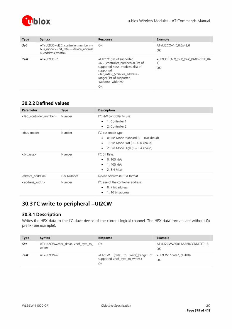
u-blox Wireless Modules - AT Commands Manual
WLS-SW-11000-CP1 Objective Specification I2C
Page 379 of 448
Type Syntax Response Example
Set AT+UI2CO=<I2C_controller_number>,<bus_mode>,<bit_rate>,<device_address>,<address_width>
OK AT+UI2CO=1,0,0,0x42,0
OK
Test AT+UI2CO=? +UI2CO: (list of supported <I2C_controller_number>s),(list of supported <bus_mode>s),(list of supported <bit_rate>),(<device_address> range),(list of supported <address_width>s)
OK
+UI2CO: (1-2),(0-2),(0-2),(0x00-0xFF),(0-1)
OK
30.2.2 Defined values
Parameter Type Description
<I2C_controller_number> Number I2C HW controller to use:
1: Controller 1
2: Controller 2
<bus_mode> Number I2C bus mode type:
0: Bus Mode Standard (0 – 100 kbaud)
1: Bus Mode Fast (0 – 400 kbaud)
2: Bus Mode High (0 – 3.4 kbaud)
<bit_rate> Number I2C Bit Rate:
0: 100 kb/s
1: 400 kb/s
2: 3,4 Mb/s
<device_address> Hex Number Device Address in HEX format
<address_width> Number I2C size of the controller address:
0: 7 bit address
1: 10 bit address
30.3 I2C write to peripheral +UI2CW
30.3.1 Description
Writes the HEX data to the I2C slave device of the current logical channel. The HEX data formats are without 0x
prefix (see example).
Type Syntax Response Example
Set AT+UI2CW=<hex_data>,<nof_byte_to_write>
OK AT+UI2CW="0011AABBCCDDEEFF",8
OK
Test AT+UI2CW=? +UI2CW: (byte to write),(range of supported <nof_byte_to_write>)
OK
+UI2CW: "data", (1-100)
OK

u-blox Wireless Modules - AT Commands Manual
WLS-SW-11000-CP1 Objective Specification I2C
Page 380 of 448
30.3.2 Defined values
Parameter Type Description
<hex_data> String Hex data sequence without prefix 0x, enclosed in double quotes, to be written to the I
2C slave device
<nof_bytes_to_write> Number Number of byte to write to the slave I2C device. Range: 1-100
30.4 I2C read from peripheral +UI2CR
30.4.1 Description
Reads <nof_bytes_to_read> of data from the I2C slave device of the current logical channel and prints them in
HEX format.
Type Syntax Response Example
Set AT+UI2CR=<nof_bytes_to_read> +UI2CR: <index_1>,<byte_1>
…
+UI2CR: <index_n>,<byte_n>
OK
AT+UI2CR=3
+UI2CR: 0: 0xA3
+UI2CR: 1: 0x0F
+UI2CR: 2: 0xDB
OK
Test AT+UI2CR=? +UI2CR: (range of supported <nof_byte_to_read>)
OK
+UI2CR: (1-100)
OK
30.4.2 Defined values
Parameter Type Description
<nof_bytes_to_read> Number Number of bytes to read from the slave I2C device. Range is 1-100.
<index1>,…,<index_n> Number Index of the byte being printed.
<byte_1>,…,<byte_n> Number n-th byte of the data, in hex mode (unquoted, prefixed by 0x).
30.5 I2C read from peripheral register +UI2CREGR
30.5.1 Description
Reads <nof_bytes_to_read> of data from the slave register of the I2C slave device of the current logical channel
and prints them in HEX format.
Type Syntax Response Example
Set AT+UI2CREGR=<register_address>,<nof_bytes_to_read>
+UI2CR: <index_1>,<byte_1>
…
+UI2CR: <index_n>,<byte_n>
OK
AT+UI2CREGR=0x42,3
+UI2CR: 0: 0xA3
+UI2CR: 1: 0x0F
+UI2CR: 2: 0xDB
OK
Test AT+UI2CREGR=? +UI2CREGR: (range of <register_address>),(range of <nof_bytes_to_read>)
OK
+UI2CREGR: (0x00-0xFF),(1-100)
OK

u-blox Wireless Modules - AT Commands Manual
WLS-SW-11000-CP1 Objective Specification I2C
Page 381 of 448
30.5.2 Defined values
Parameter Type Description
<register_address> Number Device Address in HEX format
<nof_bytes_to_read> Number Number of bytes to read from the slave I2C register (1-100)
<index1>,…,<index_n> Number Index of the byte being printed.
<byte_1>,…,<byte_n> Number n-th byte of the data, in hex mode (unquoted, prefixed by 0x).
30.6 I2C close logical channel +UI2CC
30.6.1 Description
Closes the I2C logical channel being used.
Type Syntax Response Example
Set AT+UI2CC OK AT+UI2CC
OK
Test AT+UI2CC=? AT+UI2CC
OK
AT+UI2CC
OK
The logical channel must be closed before opening a new one.

u-blox Wireless Modules - AT Commands Manual
WLS-SW-11000-CP1 Objective Specification SAP
Page 382 of 448
31 SAP
31.1 Introduction
The SIM Access Profile (SAP) allows communication between a device electrically connected to a SIM module
(SAP Server) and a device using that SIM (SAP Client). The SAP details are specified in the Bluetooth Specification
“SIM Access Profile – Interoperability Specification” [67].
u-blox modules support SAP client functionalities using a serial connection to transport the SAP messages
defined in the SAP Specification: in SAP Client mode, the u-blox wireless module uses a remote SIM, which is
physically present in the SAP Server, to perform all SIM-related operations; the local SIM card, directly connected to the module (U)SIM interface, is not accessed.
At power on SAP is disabled in the u-blox wireless module i.e. the local SIM card (directly connected to the
module (U)SIM interface) is used. It is possible to enter SAP client mode and switch to using a remote SIM via AT commands. At any time, either the local or remote SIM is exclusively used; this is transparent to AT clients: for
example when interrogating the IMSI with +CIMI, the result always refers to the “current” SIM: the local SIM’s
IMSI if SAP is not active or the remote SIM’s IMSI if SAP Client mode is active.
URCs are provided to inform the user about the state of both local and remote SIM when SAP mode is active:
The +UUSAPREMOTE URC reports information related to the “remote” SIM
The +UUSAPLOCAL URC reports information related to the local SIM card directly connected to the module (U)SIM interface
For more details refer to chapter 31.3.
Table 22 shows which indications are to be expected in case of local or remote SIM events (hot removal/insertion):
Event SAP client not active SAP client active
Local SIM removal/insertion +CIEV: 12,<value> +UUSAPLOCAL: <sim_present>
Remote SIM removal/insertion - +UUSAPREMOTE: <sim_present>
Table 22: SIM indications and SAP
For further details about SAP implementation, refer to the LISA-U series System Integration Manual [49].
SAP is not supported by LISA-U200-00S version.
u-blox wireless modules do not act as SAP server.
31.2 SAP Mode activation +USAPMODE
31.2.1 Description
Changes the SAP connection mode:
Local SIM: the local SIM is used, SAP is not active
SAP Client: the module acts as a SAP Client, a remote SIM is used
It is not possible to change the SAP mode during a call or with an active PDP context.
When entering SAP Client mode, SAP communication takes place in a separate dedicated serial channel, according to the <format> indication (currently only binary mode is supported).
The command can only be invoked from a USB or a MUX AT channel.
When invoked from a USB channel, the dedicated serial channel for SAP is USB channel.

u-blox Wireless Modules - AT Commands Manual
WLS-SW-11000-CP1 Objective Specification SAP
Page 383 of 448
When invoked from a MUX channel, the dedicated serial channel for SAP is MUX channel.
The communication between SAP client and server follows the “Connect” procedure (as specified by SAP
specification [67]), which uses the <beacon> parameter.
The actual switch between local and remote SIM takes place only when a connection has been established
between SAP Client and the SAP Server. The value of the SAP mode returned by the read command does not
change as long as the connection is active.
The SAP Client mode terminates when:
The SAP connection fails (communication lost, unrecoverable error, unsuccessful connect negotiation)
The SAP server commands a disconnection
The AT command to move back to local SIM mode is received
SAP client mode activation may result in an error code in case of SAP connection cannot be established. Result codes are listed in the Errors section (refer to chapter A.6).
Type Syntax Response Example
Set AT+USAPMODE=<sap_mode>[,<format>[,<beacon>]
OK AT+USAPMODE=0
OK
AT+USAPMODE=1,0,6
OK
Read AT+USAPMODE? +USAPMODE: <sap_mode>
OK
+USAPMODE: 0
OK
Test AT+USAPMODE=? +USAPMODE: (list of supported <sap_mode>),(list of supported <format>),(list of supported <beacon>)
OK
+USAPMODE: (0,1),0,(0-65535)
OK
31.2.2 Defined values
Parameter Type Description
<sap_mode> Number Specifies the SAP mode. Possible values:
0 (default value): Internal SIM (SAP disabled)
1: SAP Client
<format> Number Specifies the SAP communication format. This parameter can be set only if <sap_mode> is 1 or 2. Possible values:
0 (default value): Binary; SAP messages are exchanged transparently in binary format
<beacon> Number Period in seconds between consecutive CONNECT_REQ messages during the “Connect” procedure. This parameter can be set only if <sap_mode> is 1. 0 means one shot sending. Default value is 6 s. Possible range is [0-65535].
31.3 SAP Mode indications +USAPIND
31.3.1 Description
Enables or disables the URC generation for the SAP mode status change indication (+UUSAPMODE) and the detection of a local SIM (+UUSAPLOCAL) when SAP client is active.
At power up, the URCs are disabled.

u-blox Wireless Modules - AT Commands Manual
WLS-SW-11000-CP1 Objective Specification SAP
Page 384 of 448
Type Syntax Response Example
Set AT+USAPIND=<ind_mode> OK AT+USAPIND=0
OK
Read AT+USAPIND? +USAPIND: <ind_mode>
OK
+USAPIND: 0
OK
Test AT+USAPIND=? +USAPIND: (list of supported <ind_mode>)
OK
+USAPIND: (0,1)
OK
URC +UUSAPMODE: <sap_mode> +UUSAPMODE: 0
URC +UUSAPLOCAL: <sim_present> +UUSAPLOCAL: 0
31.3.2 Defined values
Parameter Type Description
<ind_mode> Number Specifies whether SAP-related URCs are enabled or disabled. Possible values:
0 (default value): Disabled
1: Enabled
<sap_mode> Number Specifies which SAP mode is currently used. Possible values:
0 (default value): Internal SIM (SAP disabled)
1: SAP Client
2: SAP Server
<sim_present> Number Specifies the status of locally attached SIM. Possible values:
0: Local SIM is present
1: Local SIM is not present

u-blox Wireless Modules - AT Commands Manual
WLS-SW-11000-CP1 Objective Specification Appendix
Page 385 of 448
Appendix
A Appendix 1
A.1 Internet suite error classes The following table lists all allowed error classes that can be provided by the <error_class> parameter for each AT error command (+UFTPER, +UHTTPER, +USMTPER) for FTP, HTTP and SMTP. For more details on the
command syntax, refer to chapter 24.5, 25.4 and 26.5.
<error_class> Meaning <error_codes> Resulting from the following commands
0 OK, no error occurred All
1 FTP Protocol error class Refer to chapter A.1.1 +UFTPC, +UFTP, +UFTPER
2 SMTP Protocol error class Refer to chapter A.1.3 +USMTP, +USMTPM, +USMTPC, +USMTPER
3 HTTP Protocol error class Refer to chapter A.1.2 +UHTTP, +UHTTPC, +UHTTPER
4 Flash File System error class Refer to chapter A.1.4 +UFTPC, +UFTPER, +UHTTPC, +UHTTPER
5 DNS error class +UFTPC, +UFTPER, +UHTTPC, +UHTTPER, +USMTPC, +USMTPER
6 Socket error class BSD error codes standard All
7 Dynamic Memory error 0 All
8 Wrong FTP API usage (e.g. missing/null parameters) Refer to chapter A.1.1 +UFTPC, +UFTP, +UFTPER
9 Wrong SMTP API usage (e.g. missing/null parameters) Refer to chapter A.1.3 +USMTP, +USMTPM, +USMTPC, +USMTPER
10 Wrong HTTP API usage (e.g. missing/null parameters) Refer to chapter A.1.2 +UHTTP, +UHTTPC, +UHTTPER
11 Syntax error in high layer Protocol (wrong/missing/corrupted data)
+UFTPC, +UFTPER, +UHTTPC, +UHTTPER, +USMTPC, +USMTPER
12 Unspecified error 0 All
A.1.1 FTP class error codes The following table lists the available values of <error_code> parameter of the last FTP operation provided
through +UFTPER AT command if <error_class>=1 or 8 (for more details, refer to the AT command description in chapter 24.5).
<err> Meaning Resulting from the following commands
0 No error +UFTPC, +UFTP
1 User missing +UFTPC
2 Password missing +UFTPC
3 Account missing +UFTPC
4 Server missing +UFTPC
5 Directory name missing +UFTPC
6 File name missing +UFTPC

u-blox Wireless Modules - AT Commands Manual
WLS-SW-11000-CP1 Objective Specification Appendix
Page 386 of 448
<err> Meaning Resulting from the following commands
7 Null parameter +UFTPC, +UFTP
8 Unknown FTP command +UFTPC, +UFTP
9 Unknown file action +UFTPC
10 Wrong FTP state +UFTPC
11 Wrong parameter +UFTPC, +UFTP
12 PSD or CSD connection not established +UFTPC
13 No memory available for allocation +UFTPC, +UFTP
14 Reserved internal code +UFTPC, +UFTP
15 Length of given web server (address or hostname) too long or too short +UFTPC, +UFTP
16 Hostname of given web server invalid +UFTPC, +UFTP
17 Address of given web server is invalid +UFTPC, +UFTP
18 Username too long or too short +UFTPC, +UFTP
19 Password too long or too short +UFTPC, +UFTP
20 Account too long or too short +UFTPC, +UFTP
21 Operation not allowed because FTP client is busy +UFTPC
22 Not possible to connect to FTP server +UFTPC
23 Error occurred in FTP request +UFTPC
24 Reserved internal code +UFTPC, +UFTP
25 FFS filename pointer is null or its length is 0 +UFTPC
26-30 Reserved internal code +UFTPC, +UFTP
31 Timeout elapsed while performing requested operation +UFTPC
32 Internal processing error +UFTPC, +UFTP
33 Not logged in +UFTPC
34 Login incorrect +UFTPC
35 File unavailable (not found or no access) +UFTPC
36 File not ready +UFTPC
37 Filename not allowed +UFTPC
38 Folder not found +UFTPC
39 Folder no access +UFTPC
40 Operation aborted by user +UFTPC
41 Permission denied +UFTPC
42 Cannot open FTP data channel +UFTPC
43 Socket invalid parameter +UFTPC
44 Invalid socket +UFTPC
45 No socket available +UFTPC
46 Cannot create socket +UFTPC
47 Cannot bind socket to network interface +UFTPC
48 Cannot resolve hostname +UFTPC
49 Cannot connect socket +UFTPC
50 Cannot get socket name +UFTPC

u-blox Wireless Modules - AT Commands Manual
WLS-SW-11000-CP1 Objective Specification Appendix
Page 387 of 448
<err> Meaning Resulting from the following commands
51 Cannot bind socket to port +UFTPC
52 Socket cannot listen +UFTPC
53 Soclet cannot accept +UFTPC
54 Socket would block +UFTPC
55 Socket cannot write +UFTPC
56 Socket cannot read +UFTPC
57 Reserved internal code +UFTPC
58 No socket data to send +UFTPC
59 Socket cannot get available data +UFTPC
60 No socket dat to read +UFTPC
61 Socket no response code found +UFTPC
62 Socket not connected +UFTPC
63 Cannot set secure socket +UFTPC
64 Socket cannot decode password +UFTPC
65 Socket cannot get size +UFTPC
66 FFS Invalid parameter +UFTPC
67 FFS invalid handle +UFTPC
68 FFS cannot open file +UFTPC
69 FFS cannot seek file +UFTPC
70 FFS cannot get file size +UFTPC
71 FFS cannot read +UFTPC
226 Closing data connection; requested file action successful (for example, file transfer or file abort)
+UFTPC
250 Requested file action okay, completed +UFTPC
350 Requested file action pending further information +UFTPC
421 Service not available, closing control connection.
User limit reached
You are not authorized to make the connection
Max connections reached
Max connections exceeded
+UFTPC
425 Cannot open data connection. +UFTPC
426 Connection closed; transfer aborted. The command opens a data connection to perform an action, but that action is canceled, and the data connection is closed.
+UFTPC
450 Requested file action not taken. File unavailable (e.g., file busy). +UFTPC
451 Requested action aborted: local error in processing. +UFTPC
452 Requested action not taken. Insufficient storage space in system. +UFTPC
500 Syntax error, command unrecognized, command line too long. +UFTPC
501 Syntax error in parameters or arguments. +UFTPC
502 Command not implemented. +UFTPC
503 Bad sequence of commands. +UFTPC
504 Command not implemented for that parameter. +UFTPC

u-blox Wireless Modules - AT Commands Manual
WLS-SW-11000-CP1 Objective Specification Appendix
Page 388 of 448
<err> Meaning Resulting from the following commands
530 User not logged in. +UFTPC
532 Need account for storing files. +UFTPC
550 Requested action not taken. File unavailable, not found, not accessible +UFTPC
552 Requested file action aborted. Exceeded storage allocation. +UFTPC
553 Requested action not taken. File name not allowed. +UFTPC
A.1.2 HTTP class error codes The following table lists the available values of <error_code> parameter of the last HTTP operation provided
through +HTTPER AT command if <error_class>=2 or 9 (for more details, refer to the AT command description in
chapter 25.4).
<err> Meaning Resulting from the following commands
0 No error +UHTTP, +UHTTPC
1 Invalid profile ID +UHTTP, +UHTTPC
2 Invalid input +UHTTP, +UHTTPC
3 Server hostname too long +UHTTP
4 Invalid server hostname +UHTTP
5 Invalid server IP address +UHTTP
6 Invalid authorization method +UHTTP
7 Server missing +UHTTPC
8 Username length exceeded +UHTTP
9 Password length exceeded +UHTTP
10 Internal error +UHTTP, +UHTTPC
11 Server connection error +UHTTPC
12 Error occurred in HTTP request +UHTTPC
13 Internal error +UHTTP, +UHTTPC
14 Internal error +UHTTP, +UHTTPC
15 Invalid POST data size +UHTTPC
16 Empty FFS file name +UHTTPC
17 Invalid FFS file length +UHTTPC
18 Invalid content-type specified +UHTTP, +UHTTPC
19 Internal error +UHTTP, +UHTTPC
20 Internal error +UHTTP, +UHTTPC
21 Internal error +UHTTP, +UHTTPC
22 PSD or CSD connection not established +UHTTPC
23 Server or proxy hostname lookup failed +UHTTPC
24 User authentication failed on server +UHTTPC
25 User authentication failed on proxy +UHTTPC
26 Connection timed out +UHTTPC

u-blox Wireless Modules - AT Commands Manual
WLS-SW-11000-CP1 Objective Specification Appendix
Page 389 of 448
A.1.3 SMTP class error codes The following table lists the available values of <error_code> parameter of the last SMTP operation provided
through +USMTPER AT command if <error_class>=3 or 10 (for more details, refer to the AT command description in chapter 26.5).
<err> Meaning Resulting from the following commands
0 No error +USMTP, +USMTPM, +USMTPC
1 Server missing +USMTPC
2 Sender address missing +USMTPC
3 Receiver address missing +USMTPC
4 Maximum number of receivers exceeded +USMTPC
5 Maximum address length exceeded +USMTPC
6 Internal error +USMTPM, +USMTPC
7 Maximum subject length exceeded +USMTPC
8 Maximum number of attachments exceeded +USMTPC
9 Wrong SMTP state +USMTPM, +USMTPC
10 Wrong parameter +USMTPC
11 Internal error +USMTP, +USMTPM, +USMTPC
12 PSD or CSD connection not established +USMTPC
A.1.4 File System Class Error codes The following table lists the available values of <error_code> parameter of the last FTP, HTTP or SMTP operation provided through +UFTPER, +UHTTPER +USMTPER AT commands if the <error_class> is 4 “Flash File System
error class” (for more details, refer to the AT command description in chapter 24.5, 25.4 and 26.5.
<err> Meaning Resulting from the following commands
2 Operation performed with success +UHTTPC, +UFTPC, +USMTPC
3 Initialization in progress +UHTTPC, +UFTPC, +USMTPC
4 File already opened +UHTTPC, +UFTPC, +USMTPC
5 File not opened +UHTTPC, +UFTPC, +USMTPC
6 File not found +UHTTPC, +UFTPC, +USMTPC
7 File already created +UHTTPC, +UFTPC, +USMTPC
8 Illegal id +UHTTPC, +UFTPC, +USMTPC
9 Illegal file handle +UHTTPC, +UFTPC, +USMTPC
10 Illegal type +UHTTPC, +UFTPC, +USMTPC
11 Illegal mode +UHTTPC, +UFTPC, +USMTPC
12 File range error +UHTTPC, +UFTPC, +USMTPC
13 The operation is not possible +UHTTPC, +UFTPC, +USMTPC
14 Write error +UHTTPC, +UFTPC, +USMTPC
15 User id error +UHTTPC, +UFTPC, +USMTPC

u-blox Wireless Modules - AT Commands Manual
WLS-SW-11000-CP1 Objective Specification Appendix
Page 390 of 448
<err> Meaning Resulting from the following commands
16 Internal fatal error +UHTTPC, +UFTPC, +USMTPC
17 Memory resource error +UHTTPC, +UFTPC, +USMTPC
18 Maximum number of files exceeded +UHTTPC, +UFTPC, +USMTPC
19 Memory not available +UHTTPC, +UFTPC, +USMTPC
20 Invalid filename +UHTTPC, +UFTPC, +USMTPC
21 Streaming not enabled +UHTTPC, +UFTPC, +USMTPC
22 Operation not allowed on static file +UHTTPC, +UFTPC, +USMTPC
23 Memory table inconsistency +UHTTPC, +UFTPC, +USMTPC
24 Not a factory default file +UHTTPC, +UFTPC, +USMTPC
25 Requested memory temporary not available +UHTTPC, +UFTPC, +USMTPC
26 Operation not allowed for a directory +UHTTPC, +UFTPC, +USMTPC
27 Space in the directory space not available +UHTTPC, +UFTPC, +USMTPC
28 Too many streaming files opened +UHTTPC, +UFTPC, +USMTPC
29 Requested dynamic memory temporary not available +UHTTPC, +UFTPC, +USMTPC
30 The user provided a NULL parameter instead of a suitable buffer +UHTTPC, +UFTPC, +USMTPC

u-blox Wireless Modules - AT Commands Manual
WLS-SW-11000-CP1 Objective Specification Appendix
Page 391 of 448
A.2 Ping error codes The following table lists the available values of <error_code> parameter of the last PING operation provided
through +UUPINGER unsolicited indication.
<err> Meaning Resulting from the following commands
0 Success (no error) +UPING
1 – 6 Internal error (ping level) +UPING
7 Empty remote host +UPING
8 Cannot resolve host +UPING
9 Unsupported IP version (RFU) +UPING
10 Invalid IPv4 address +UPING
11 Invalid IPv6 address (RFU) +UPING
12 Remote host too long +UPING
13 Invalid payload size +UPING
14 Invalid TTL value +UPING
15 Invalid timeout value +UPING
16 Invalid retries number +UPING
17 PSD or CSD connection not established +UPING
100 – 105 Internal error (ICMP level) +UPING
106 Error creating socket for ICMP +UPING
107 Error settings socket options for ICMP +UPING
108 Cannot end ICMP packet +UPING
109 Read for ICMP packet failed +UPING
110 Received unexpected ICMP packet +UPING
111-115 Internal error (socket level) +UPING
A.3 Internal TCP/UDP/IP stack class error codes The following table lists all allowed error classes that can be provided by the internal TCP/UDP/IP stack through
+USOER and +USOCTL (with param_id=1) AT commands (for more details, refer to the AT command description
in chapters 23.6 and 23.15).
<err> Meaning Resulting from the following commands
0 No error +USOCR, +USOSO,+USOGO, +USOCO, +USOWR, +USOST, +USORD, +USORF, +USOLI
2 ENOENT - No such resource (internal error) +USOCR, +USOSO,+USOGO, +USOCO, +USOWR, +USOST, +USORD, +USORF, +USOLI
4 EINTR - Interrupted system call (internal error) +USOCR, +USOSO,+USOGO, +USOCO, +USOWR, +USOST, +USORD, +USORF, +USOLI
5 EIO - I/O error (internal error) +USOCR, +USOSO,+USOGO, +USOCO, +USOWR, +USOST, +USORD, +USORF, +USOLI
9 EBADF - Bad file descriptor (internal error) +USOCR, +USOSO,+USOGO, +USOCO, +USOWR, +USOST, +USORD, +USORF, +USOLI

u-blox Wireless Modules - AT Commands Manual
WLS-SW-11000-CP1 Objective Specification Appendix
Page 392 of 448
<err> Meaning Resulting from the following commands
10 ECHILD - No child processes (internal error) +USOCR, +USOSO,+USOGO, +USOCO, +USOWR, +USOST, +USORD, +USORF, +USOLI
11 EWOULDBLOCK - Current operation would block, try again +USOWR
12 ENOMEM - Out of memory (internal error) +USOCR, +USOSO,+USOGO, +USOCO, +USOWR, +USOST, +USORD, +USORF, +USOLI
14 EFAULT - Bad address (internal error) +USOCR, +USOSO,+USOGO, +USOCO, +USOWR, +USOST, +USORD, +USORF, +USOLI
22 EINVAL - Invalid argument +USOCR, +USOSO,+USOGO, +USOCO, +USOWR, +USOST, +USORD, +USORF, +USOLI
32 EPIPE - Broken pipe (internal error) +USOCR, +USOSO,+USOGO, +USOCO, +USOWR, +USOST, +USORD, +USORF, +USOLI
38 ENOSYS - Function not implemented +USOSO, +USOGO
92 ENOPROTOOPT - Protocol not available +USOCR
98 EADDRINUSE - Address already in use +USOLI
103 ECONNABORTED - Software caused connection abort +USOCR, +USOSO,+USOGO, +USOCO, +USOWR, +USOST, +USORD, +USORF, +USOLI
104 ECONNRESET - Connection reset by peer +USOCR, +USOSO,+USOGO, +USOCO, +USOWR, +USOST, +USORD, +USORF, +USOLI
105 ENOBUFS - No buffer space available +USOCR, +USOSO,+USOGO, +USOCO, +USOWR, +USOST, +USORD, +USORF, +USOLI
107 ENOTCONN - Transport endpoint is not connected +USOCR, +USOSO,+USOGO, +USOCO, +USOWR, +USOST, +USORD, +USORF, +USOLI
108 ESHUTDOWN - Cannot send after transport endpoint shutdown +USOCR, +USOSO,+USOGO, +USOCO, +USOWR, +USOST, +USORD, +USORF, +USOLI
110 ETIMEDOUT - Connection timed out +USOCO, +USOST, +USORD, +USORF
113 EHOSTUNREACH - No route to host +USOCO, +USOWR, +USOST, +USORD, +USORF
115 EINPROGRESS - Operation now in progress +USOCR, +USOSO,+USOGO, +USOCO, +USOWR, +USOST, +USORD, +USORF, +USOLI
160 ENSRNODATA - DNS server returned answer with no data +UDNSRN
161 ENSRFORMERR - DNS server claims query was misformatted +UDNSRN
162 ENSRSERVFAIL - DNS server returned general failure +UDNSRN
163 ENSRNOTFOUND - Domain name not found +UDNSRN
164 ENSRNOTIMP - DNS server does not implement requested operation +UDNSRN
165 ENSRREFUSED - DNS server refused query +UDNSRN
166 ENSRBADQUERY - Misformatted DNS query +UDNSRN
167 ENSRBADNAME - Misformatted domain name +UDNSRN
168 ENSRBADFAMILY - Unsupported address family +UDNSRN
169 ENSRBADRESP - Misformatted DNS reply +UDNSRN
170 ENSRCONNREFUSED - Could not contact DNS servers +UDNSRN
171 ENSRTIMEOUT - Timeout while contacting DNS servers +UDNSRN
172 ENSROF - End of file +UDNSRN
173 ENSRFILE - Error reading file +UDNSRN
174 ENSRNOMEM - Out of memory +UDNSRN
175 ENSRDESTRUCTION - Application terminated lookup +UDNSRN

u-blox Wireless Modules - AT Commands Manual
WLS-SW-11000-CP1 Objective Specification Appendix
Page 393 of 448
<err> Meaning Resulting from the following commands
176 ENSRQUERYDOMAINTOOLONG - Domain name is too long +UDNSRN
177 ENSRCNAMELOOP - Domain name is too long +UDNSRN

u-blox Wireless Modules - AT Commands Manual
WLS-SW-11000-CP1 Objective Specification Appendix
Page 394 of 448
A.4 FOAT Error Messages Refer to chapter 17.2 for +UFWUPD command description.
Response Description
ERROR1 The operation has been interrupted and the actual FW is unchanged; the module drops out from Firmware Update Mode
ERROR2 The operation has been interrupted during FW updating; the actual firmware is corrupted and the module remains in Firmware Update Mode
ERROR3 The signature check fails
ERROR4 The module has received unexpected EOT because not all excepted bytes have been received
ERROR5 The boot does not support the selected baudrate
ERROR6 Invalid AT command sent during boot
FLS header decoding failed An error occurs during decoding of file header
Buffer Data Overrun The buffers are not filled at least with a 1029 packet: data comes too slowly
Timeout The command must be re-sent: no data is coming
A.5 FOTA Error codes In case of an upgrade several entities are involved: the application that handles the SMS, the data connection,
the HTTP download and the UA; all these facilities have their own errors and the report operation result combines them in this way. Refer to chapter 17.1 for +UFOTA command description.
16 bit 16 bit
Error type Error code
The error type bits are mapped in this way:
15 14 13 12 11 10 9 8 7 6 5 4 3 2 1 0
UA error
Data
conn. error
SMS error
HTTP error
The allowed error codes are listed in the following tables:
A.5.1 FOTA class - UA errors
Response Description
invocation errors
2 error in a run parameter
3 no valid UPI found
4 future use
update package errors
11 expected length error

u-blox Wireless Modules - AT Commands Manual
WLS-SW-11000-CP1 Objective Specification Appendix
Page 395 of 448
Response Description
12 expected length error
13 structural error
14 signature error
15 foreign key not signed
16 not for current version
17 non-compatible UPI
18 update for UPI does not match its version
19 update for UPI does not match its version
resources errors
30 given RAM is not enough
31 does not behave as RAM
32 new version is too big
33 flash writing failure
34 flash erasing failure
35 flash reading failure
36 memory allocation failure
final-stage errors
40 cannot restore new
41 signature error of new
42 foreign key not signed
43 one API function is not declared recommended
File System update
205 file does not exist
206 RO or no access rights
207 file does not exist
208 no access rights
209 cannot resize file
210 cannot read specified size
211 cannot close file handle
300 bad operation number for FS update
301 bad operation number for FW update
302 unsupported compression
303 Cannot apply reverse update for delta not generated as reverse delta
304 number of backup buffers given to UPI does not match number in delta file
305 Sector size mismatch between UPI and delta
306 UPI was not compiled to support reverse update
307 UPI was not compiled to support IFS on compressed images
308 UPI was not compiled to support IFS
309 Image verified is not source image
310 In scout only operation we should do only verify of image

u-blox Wireless Modules - AT Commands Manual
WLS-SW-11000-CP1 Objective Specification Appendix
Page 396 of 448
Response Description
311 There is not enough RAM to run with operation=2
312 Delta file too long - corrupted
313 Mismatch between deletes sig and delta deletes buffers signature
314 Number of fragments in section is not 1
315 Over all number of backup sects too big
316 Delta file is corrupt: signature mismatch between delta header signature and calculated signature
317 Source file size mismatch from file on device to delta file size
318 File signature does not match signature
319 Signature for the target buffer does not match the one stored in the delta file
320 Too many dirty buffers
321 UPI version mismatch between UPI and delta
322 Scout version mismatch between UPI and delta
A.5.2 FOTA class - Data Connection errors
Response Description
1 Generic operation error
2 Network does not recognize a valid APN
3 Network does not recognize a valid userid or password
4 QoS parameters are inconsistent (i.e. minimum values greater that the required ones)
5 Network failure
6 The context is busy in some other operation
7 Cannot read or write on the flash for unknown reasons
8 Illegal MS
9 Illegal ME
10 GPRS services not allowed
11 PLMN not allowed
12 Location area not allowed
13 National roaming not allowed in this location area
14 Service option not supported
15 Requested service option not subscribed
16 Service option temporarily out of order
17 NS-API already used
A.5.3 FOTA class - SMS Errors
Response Description
1 SMS URL too long
2 Invalid SMS URL, missing “http://”
3 Invalid SMS URL, missing file path

u-blox Wireless Modules - AT Commands Manual
WLS-SW-11000-CP1 Objective Specification Appendix
Page 397 of 448
Response Description
4 Wrong security check code
5 Delta firmware unavailable on FOTA server
A.5.4 FOTA class - HTTP errors
Response Description
1 FTP Protocol error class
2 SMTP Protocol error class
3 HTTP Protocol error class
4 flash file system error class
5 DNS error class
6 socket error class
7 dynamic memory error
8 wrong FTP API usage (ex missing/null parameters)
9 wrong SMTP API usage (ex missing/null parameters)
10 wrong HTTP API usage (ex missing/null parameters)
11 syntax error in high layer Protocol (wrong/missing/corrupted data)
12 unspecified error
A.6 Mobile Termination error result codes +CME ERROR
The error codes from 1621 to 1649 are supported only by LEON-G100 / LEON-G200 series from
LEON-G100-06x / LEON-G200-06x and subsequent versions.
<err> Meaning Resulting from the following commands
0 Phone failure undeterminated
1 No connection to phone
2 Phone-adaptor link reserved
3 Operation not allowed Refer to the footnote5
4 Operation not supported Refer to the footnote5, +CMER and +UCIND
5 PH-SIM PIN required Refer to the footnote5
10 SIM not inserted Refer to the footnote5
11 SIM PIN required Refer to the footnote5
12 SIM PUK required Refer to the footnote5
13 SIM failure Refer to the footnote5
5 +CACM, +CALA, +CALD,+CALM, +CAMM,+CAOC, +CBC,+CBST, +CCFC, +CCLK, +CCUG, +CCWA, +CCWE, +CEER, +CFUN, +CGACT, +CGATT, +CGCLASS, +CGDATA, +CGDCONT, +CGEREP, +CGMI, +CGMM, +CGMR, +CGPADDR, +CGQMIN, +CGQREQ, +CGREG, +CGSMS, +CGSN, +CHLD, +CHUP, +CIMI, +CIND, +CLAC, +CLCC, +CLCK, +CLIP, +CLIR, +CLVL, +CMEE, +CMOD, +CMUT, +CMUX, +CNUM, +COLP, +COPS, +CPAS, +CPBF, +CPBR, +CPBS, +CPBW, +CPIN, +CPOL, +CPUC, +CPWD, +CR, +CRC, +CREG, +CRLP, +CRSL, +CRSM, +CSCS, +CSGT, +CSNS, +CSQ, +CSSN, +CSTA, +CTFR, +CTZR, +CTZU

u-blox Wireless Modules - AT Commands Manual
WLS-SW-11000-CP1 Objective Specification Appendix
Page 398 of 448
<err> Meaning Resulting from the following commands
14 SIM busy Refer to the footnote5
15 SIM wrong Refer to the footnote5
16 Incorrect password +CLCK, +CPWD, +CPIN, ATD*…#…
17 SIM PIN2 required
18 SIM PUK2 required
20 Memory full +CPBW, +CPOL
21 Invalid index +CPBR, +CPBW
22 Not found +COPS, +CHLD, +CGATT, ATD*…#…
23 Memory failure +CSAS, +CRES, +CSGT
24 Text string too long +CPBW
25 Invalid characters in text string ATD*…#…
26 Dial string too long ATD, +CPBW
27 Invalid characters in dial string ATD, +CPBW, …
30 No network service ATD, +COPS, +CLIR, …
31 Network timeout ATD
32 Network not allowed - emergency calls only
40 Network personalisation PIN required
41 Network personalisation PUK required
42 Network subset personalisation PIN required
43 Network subset personalisation PUK required
44 Service provider personalisation PIN required
45 Service provider personalisation PUK required
46 Corporate personalisation PIN required
47 Corporate personalisation PUK required
50 Incorrect parameters +CIND
100 Unknown Commands with wrong syntax
103 Illegal MS +CGATT, +COPS
106 Illegal ME +CGATT, +COPS
107 GPRS services not allowed +CGATT
108 GPRS and non GPRS services not allowed +CGATT
111 PLMN not allowed +CGATT, +COPS
112 Location area not allowed +CGATT, +COPS
113 Roaming not allowed in this location area +CGATT, +COPS
132 Service option not supported +CGACT, or other non-GPRS commands
133 Requested service option not subscribed +CGACT, or other non-GPRS commands
134 Service option temporarily out of order +CGACT, or other non-GPRS commands
135 NS-api already used
148 Unspecified GPRS error all GPRS related commands
149 PDP authentication failure +CGACT
150 Invalid mobile class all GPRS related commands

u-blox Wireless Modules - AT Commands Manual
WLS-SW-11000-CP1 Objective Specification Appendix
Page 399 of 448
<err> Meaning Resulting from the following commands
156 User Busy +UI2CO, +UI2CW, +UI2CREGR, +UI2CR, +UI2CC
254 Invalid error mapping
255 Internal error
701 Incorrect security code
702 Max attempts reached
1001 Unassigned (unallocated) number
1003 No rout to destination
1006 Channel unacceptable
1008 Operator determined barring
1016 Normal call clearing
1017 User busy
1018 No user responding
1019 User alerting, no answer
1021 Call rejected
1022 Number changed
1026 Non selected user clearing
1027 Destination out of order
1028 Invalid number format (incomplete number)
1029 Facility rejected
1030 Response to STATUS ENQUIRY
1031 Normal, unspecified
1034 No circuit/channel available
1038 Network out of order +COPS, +CGATT
1041 Temporary failure +COPS, +CGATT
1042 Switching equipment congestion +COPS, +CGATT
1043 Access information discarded
1044 requested circuit/channel not available
1047 Resources unavailable, unspecified
1049 Quality of service unavailable
1050 Requested facility not subscribed
1055 Incoming calls barred within the CUG
1057 Bearer capability not authorized
1058 Bearer capability not presently available
1063 Service or option not available, unspecified
1065 Bearer service not implemented
1068 ACM equal to or greater than ACMmax
1069 Requested facility not implemented
1070 Only restricted digital information bearer capability is available
1079 Service or option not implemented, unspecified
1081 Invalid transaction identifier value

u-blox Wireless Modules - AT Commands Manual
WLS-SW-11000-CP1 Objective Specification Appendix
Page 400 of 448
<err> Meaning Resulting from the following commands
1087 User not member of CUG
1088 Incompatible destination
1091 Invalid transit network selection
1095 Semantically incorrect message
1096 Invalid mandatory information
1097 Message type non-existent or not implemented
1098 Message type not compatible with protocol state
1099 Information element non-existent or not implemented
1100 Conditional IE error
1101 Message not compatible with protocol state
1102 Recovery on timer expiry
1111 Protocol error, unspecified
1127 Interworking, unspecified
1279 Number not allowed
1283 CCBS possible
1500 Wrong GPIO identifier +UGPIOC, +UGPIOR, +UGPIOW
1501 Set GPIO default error +UGPIOC
1502 Select GPIO mode error +UGPIOC
1503 Read GPIO error +UGPIOR
1504 Write GPIO error +UGPIOW
1520 Wrong ADC identifier +UADC
1521 Read ADC error +UADC
1540 Wrong ringer identifier +URNG
1550 GPRS generic operation error +UPSD, +UPSDA
1551 GPRS invalid APN +UPSDA
1552 GPRS authentication failure +UPSDA
1553 GPRS QoS parameters inconsistent +UPSD
1554 GPRS network failure +UPSDA, +CGATT, +CGACT
1555 GPRS context busy +UPSD, +UPSDA
1556 CSD generic operation error +UCSD, +UCSDA, +UCSND
1557 CSD undefined profile +UCSDA
1558 CSD context busy +UCSD, +UCSDA
1600 FFS error
1612 File not found +UPLAYFILE, +UDELFILE
1620 Buffer full +USOWR +USOST
1621 FFS initializing +UDWNFILE
1622 FFS already open file +UDWNFILE
1623 FFS not open file +UDWNFILE
1624 FFS file not found +UDWNFILE
1625 FFS file already created +UDWNFILE

u-blox Wireless Modules - AT Commands Manual
WLS-SW-11000-CP1 Objective Specification Appendix
Page 401 of 448
<err> Meaning Resulting from the following commands
1626 FFS illegal id +UDWNFILE
1627 FFS illegal file handle +UDWNFILE
1628 FFS illegal type +UDWNFILE
1629 FFS illegal mode +UDWNFILE
1630 FFS file range +UDWNFILE
1631 FFS operation not possible +UDWNFILE
1632 FFS write error +UDWNFILE
1633 FFS user id error +UDWNFILE
1634 FFS internal fatal error +UDWNFILE
1635 FFS memory resource error +UDWNFILE
1636 FFS maximum number of files exceeded +UDWNFILE
1637 FFS memory not available +UDWNFILE
1638 FFS invalid filename +UDWNFILE
1639 FFS streaming not enabled +UDWNFILE
1640 FFS operation not allowed on static file +UDWNFILE
1641 FFS memory table inconsistency +UDWNFILE
1642 FFS not a factory default file +UDWNFILE
1643 FFS requested memory temporary not available +UDWNFILE
1644 FFS operation not allowed for a directory +UDWNFILE
1645 FFS directory space not available +UDWNFILE
1646 FFS too many streaming files open +UDWNFILE
1647 FFS requested dynamic memory temporary not available +UDWNFILE
1648 FFS user provided a NULL parameter instead of a suitable buffer +UDWNFILE
1649 FFS timeout +UDWNFILE
1650 Command line too long All commands
1660 Call barred - Fixed dialing numbers only D
1700 GPS GPIO not configured +UGPS
1701 GPS GPIO ownership error +UGPS
1702 Invalid operation with GPS ON +UGPRF, +ULOC
1703 Invalid operation with GPS OFF +UGPS, +UGTMR, +UGAOS, +UGUBX
1704 Invalid GPS aiding mode +UGPS, +UGAOS
1705 Reserved GPS aiding mode +UGPS
1706 GPS aiding mode already set +UGPS
1707 Invalid GPS trace mode +UGPRF
1708 Parameter valid only in case of GPS OTA +UGPRF
1709 GPS trace invalid server +UGPRF
1710 Invalid TimeZone +UGTMR
1711 Invalid value +UGZDA, +UGGGA, +UGGLL, +UGGSV, +UGRMC, +UGVTG,+UGGSA
1712 Invalid parameter +UGAOF, +UGAOP

u-blox Wireless Modules - AT Commands Manual
WLS-SW-11000-CP1 Objective Specification Appendix
Page 402 of 448
<err> Meaning Resulting from the following commands
1713 Invalid operation with LOC running / GPS Busy +UGPS
1800 No ongoing call +UIBMDATA
1801 IBM busy +UIBMDATA
1802 IBM feature off +UIBMDATA
1803 Wrong IBM requested (RFU)
1804 Audio resource not available +UIBMDATA
1900 No SAP Server Connection +USAPMODE
1901 SAP Protocol Error +USAPMODE
1902 SAP Connection failure +USAPMODE
1903 SAP Server Disconnection +USAPMODE

u-blox Wireless Modules - AT Commands Manual
WLS-SW-11000-CP1 Objective Specification Appendix
Page 403 of 448
A.7 Message service failure result codes +CMS ERROR
<err> Meaning Resulting from the following commands
1 Unassigned (unallocated) number
5 Delta firmware unavailable on FOTA server
8 Operator determined barring
10 Call barred
17 Network failure
21 Short message transfer rejected
22 Memory capacity exceeded
27 Destination out of service
28 Unidentified subscriber
29 Facility rejected
30 Unknown Subscriber
38 Network out of order
41 Temporary failure
42 Congestion
47 Resources unavailable, unspecified
50 Requested facility not subscribed
69 Requested facility not implemented
81 Invalid short message reference value
95 Invalid message, unspecified
96 invalid mandatory information
97 Message type non-existent or not implemented
98 Message not compatible with short message protocol state
99 Information element non-existent or not implemented
111 Protocol error, unspecified
127 Interworking, unspecified
128 Telematic interworking not supported
129 Short message type 0 not supported
130 Cannot replace short message
143 Unspecified TP-PID error
144 Data coding scheme (alphabet) not supported
145 Message class not supported
159 Unspecified TP-DCS error
160 Command cannot be actioned
161 Command unsupported
175 Unspecified TP-Command error
176 TPDU not supported
192 SC busy
193 No SC subscription

u-blox Wireless Modules - AT Commands Manual
WLS-SW-11000-CP1 Objective Specification Appendix
Page 404 of 448
<err> Meaning Resulting from the following commands
194 SC system failure
195 Invalid SME address
196 Destination SME barred
197 SM Rejected-Duplicate SM
198 TP-VPF not supported
199 TP-VP not supported
208 SIM SMS storage full
209 No SMS storage capability in SIM
210 Error in MS
211 Memory Capacity Exceeded
212 SIM Application Toolkit Busy
213 SIM data download error
300 ME failure
301 SMS service of ME reserved +CSMS
302 Operation not allowed all SMS commands
303 operation not supported all SMS commands
305 Invalid Text mode parameter
310 SIM not inserted all SMS commands
311 SIM PIN necessary all SMS commands
312 PH-SIM PIN necessary all SMS commands
313 SIM failure all SMS commands
314 SIM busy all SMS commands
315 SIM wrong all SMS commands, +COPS
320 memory failure +CMGR, +UCMGP
321 invalid memory index +CMGR, +CMGL, +UCMGR, +CMGD, +UCMGP
322 memory full
330 SMSC address unknown
331 no network service
332 network timeout +CNMA
500 unknown error commands with wrong syntax
516 MS invalid TP-Message-Type-Indicator
517 MS no TP-Status-Report in Phase 1
518 MS no TP-Reject-Duplicate in phase 1
519 MS no TP-Replay-Path in Phase 1
520 MS no TP-User-Data-Header in Phase 1
521 MS missing TP-Validity-Period
522 MS invalid TP-Service-Centre-Time-Stamp
523 MS missing TP-Destination- Address
524 MS invalid TP-Destination-Address
525 MS missing Service-Centre-Address
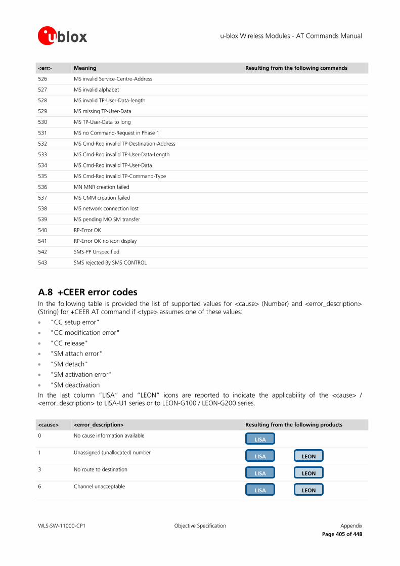
u-blox Wireless Modules - AT Commands Manual
WLS-SW-11000-CP1 Objective Specification Appendix
Page 405 of 448
<err> Meaning Resulting from the following commands
526 MS invalid Service-Centre-Address
527 MS invalid alphabet
528 MS invalid TP-User-Data-length
529 MS missing TP-User-Data
530 MS TP-User-Data to long
531 MS no Command-Request in Phase 1
532 MS Cmd-Req invalid TP-Destination-Address
533 MS Cmd-Req invalid TP-User-Data-Length
534 MS Cmd-Req invalid TP-User-Data
535 MS Cmd-Req invalid TP-Command-Type
536 MN MNR creation failed
537 MS CMM creation failed
538 MS network connection lost
539 MS pending MO SM transfer
540 RP-Error OK
541 RP-Error OK no icon display
542 SMS-PP Unspecified
543 SMS rejected By SMS CONTROL
A.8 +CEER error codes In the following table is provided the list of supported values for <cause> (Number) and <error_description>
(String) for +CEER AT command if <type> assumes one of these values:
"CC setup error"
"CC modification error"
"CC release"
"SM attach error"
"SM detach"
"SM activation error"
"SM deactivation
In the last column “LISA” and “LEON” icons are reported to indicate the applicability of the <cause> / <error_description> to LISA-U1 series or to LEON-G100 / LEON-G200 series.
<cause> <error_description> Resulting from the following products
0 No cause information available
1 Unassigned (unallocated) number
3 No route to destination
6 Channel unacceptable
LEON LISA
LEON LISA
LEON LISA
LISA

u-blox Wireless Modules - AT Commands Manual
WLS-SW-11000-CP1 Objective Specification Appendix
Page 406 of 448
<cause> <error_description> Resulting from the following products
8 Operator determined barring
16 Normal call clearing
17 User busy
18 No user responding
19 User alerting, no answer
21 Call rejected
22 Number changed
26 Non selected user clearing
27 Destination out of order
28 Invalid number format (incomplete number)
29 Facility rejected
30 Response to STATUS ENQUIRY
31 Normal, unspecified
34 No circuit/channel available
38 Network out of order
41 Temporary failure
42 Switching equipment congestion
43 Access information discarded
44 Requested circuit/channel not available
47 Resources unavailable, unspecified
49 Quality of service unavailable
50 Requested facility not subscribed
55 Incoming calls barred within the CUG
57 Bearer capability not authorized
58 Bearer capability not presently available
LEON LISA
LEON LISA
LEON LISA
LEON LISA
LEON LISA
LEON LISA
LEON LISA
LEON LISA
LEON LISA
LEON LISA
LEON LISA
LEON LISA
LEON LISA
LEON LISA
LEON LISA
LEON LISA
LEON LISA
LEON LISA
LEON LISA
LEON LISA
LEON LISA
LEON LISA
LEON LISA
LEON LISA
LEON LISA

u-blox Wireless Modules - AT Commands Manual
WLS-SW-11000-CP1 Objective Specification Appendix
Page 407 of 448
<cause> <error_description> Resulting from the following products
63 Service or option not available, unspecified
65 Bearer service not implemented
68 ACM equal to or greater than ACMmax
69 Requested facility not implemented
70 Only restr. digital information bearer capability
79 Service or option not implemented, unspecified
81 Invalid transaction identifier value
87 User not member of CUG
88 Incompatible destination
91 Invalid transit network selection
95 Semantically incorrect message
96 Invalid mandatory information
97 Message type non-existent or not implemented
98 Message type not compatible with protocol state
99 Information element non-existent or not implemented
100 Conditional IE error
101 Message not compatible with protocol state
102 Recovery on timer expiry
103 Illegal MS
106 Illegal ME
107 GPRS service not allowed
112 Location area not allowed
113 Roaming not allowed in this location area
132 Service not supported
133 Service not subscribed
LISA
LISA
LISA
LISA
LISA
LISA
LISA
LEON LISA
LEON LISA
LEON LISA
LEON LISA
LEON LISA
LEON LISA
LEON LISA
LEON LISA
LEON LISA
LEON LISA
LEON LISA
LEON LISA
LEON LISA
LEON LISA
LEON LISA
LEON LISA
LEON LISA
LEON LISA

u-blox Wireless Modules - AT Commands Manual
WLS-SW-11000-CP1 Objective Specification Appendix
Page 408 of 448
<cause> <error_description> Resulting from the following products
134 Service option temporarily out of order
148 Unspecified GPRS error
149 PDP authentification error
111 Protocol error, unspecified
127 Interworking, unspecified
256 Internal, unspecified
257 Out of memory
258 Invalid parameters
259 Data call active
260 Speech call active
262 Missing ACM information
263 Temporary forbidden
264 Called party is blacklisted
265 Blacklist is full
266 No service
267 Limited service
268 Client conflict
269 Dual service call active
271 Unknown SIM error
274 Active Client is Gone
277 SIM status failure
278 Rejected by call control
279 FDN failed
280 BDN failed
283 CCBS possible
LISA
LISA
LISA
LISA
LISA
LISA
LISA
LISA
LISA
LISA
LISA
LISA
LISA
LISA
LISA
LISA
LISA
LISA
LISA
LISA
LEON LISA
LEON LISA
LISA
LISA
LISA

u-blox Wireless Modules - AT Commands Manual
WLS-SW-11000-CP1 Objective Specification Appendix
Page 409 of 448
<cause> <error_description> Resulting from the following products
285 LND overflow
287 MM network failure unspecified
288 MM no service
289 MM access class barred
290 MM RR no resource
291 MM ME busy
292 MM unspecified
301 MMI not registered
303 Rejected by user
304 Rejected due to time out
306 Disconnected due to SIM-Toolkit call setup
307 Pending SIM-Toolkit call setup
310 SIM reset
340 MM sapi3 release
341 MM lower layer failure
342 MM authentification failure
343 MM PS reject
344 MM service rejected
345 MM abort by network
346 MM timeout
347 MM detach
348 MM RR connection release
349 MM not registered
350 MM reestablishment failure
351 Failure due to handover
LISA
LISA
LISA
LISA
LISA
LISA
LISA
LISA
LISA
LISA
LISA
LISA
LISA
LISA
LISA
LISA
LISA
LISA
LISA
LISA
LISA
LISA
LISA
LISA
LISA

u-blox Wireless Modules - AT Commands Manual
WLS-SW-11000-CP1 Objective Specification Appendix
Page 410 of 448
<cause> <error_description> Resulting from the following products
352 Link establishment failure
353 Random access failure
354 Radio link aborted
355 Lower layer failure in Layer 1
356 Immediate Assignment Reject
357 Failure due to paging
358 Abnormal release unspecified
359 Abnormal release channel unacceptable
360 Abnormal release timer expired
361 Abnormal release no act on radio path
362 Preemptive release
363 UTRAN configuration unknown
364 Handover impossible
365 Channel mode unacceptable
366 Frequency not implemented
367 Originator leaving call group area
368 Lower layer failure from network
369 Call already cleared
370 Semantically incorrect message
371 Invalid mandatory info
372 Message type non existing
373 Message type incompatible in state
374 Conditional information element error
375 No cell allocation available
376 Protocol error unspecified
LISA
LISA
LISA
LISA
LISA
LISA
LISA
LISA
LISA
LISA
LISA
LISA
LISA
LISA
LISA
LISA
LISA
LISA
LISA
LISA
LISA
LISA
LISA
LISA
LISA

u-blox Wireless Modules - AT Commands Manual
WLS-SW-11000-CP1 Objective Specification Appendix
Page 411 of 448
<cause> <error_description> Resulting from the following products
377 Normal event
378 Unspecified
379 Preemptive release
380 Congestion
381 RE establishment reject
382 Directed sig conn establishment
383 User inactivity
384 Lower layer failure downlink
385 Lower layer failure uplink
386 Cell barred due to authentication failure
387 signalling connection release
388 CS connection release triggered by MM
389 RRC connection establishment failure
390 RRC connection establishment reject with redirection
391 resource conflict
392 Layer 2 sequence error
393 Layer 2 T200 exp N200 plus 1 times
394 Layer 2 unsolicited DM resp MFES
395 Layer 2 contention resolution
396 Layer 2 normal cause
397 RR connection release due to BAND change (2G)
400 MM RR connection error while release
Outgoing calls barred within CUG
No CUG selected
Unknown CUG index
LEON
LEON
LEON
LISA
LISA
LISA
LISA
LISA
LISA
LISA
LISA
LISA
LISA
LISA
LISA
LISA
LISA
LISA
LISA
LISA
LISA
LISA
LISA
LISA
LISA

u-blox Wireless Modules - AT Commands Manual
WLS-SW-11000-CP1 Objective Specification Appendix
Page 412 of 448
<cause> <error_description> Resulting from the following products
CUG index incompatible with requested basic service
CUG call failure, unspecified
CLIR not subscribed
CCBS possible
CCBS not possible
Normal, unspecified
Resources unavailable, unspecified
Service or option not available, unspecified
Service or option not implemented, unspecified
Semantically incorrect message
Protocol error, unspecified
Interworking, unspecified
Unknown
normal
alternate call unsuccessful modify
mobile originated unsuccessful call setup
mobile terminated unsuccessful call setup
unsuccessful in-call-modification
normal user request
last call release
last data call release
unsuccessful GPRS attach
GPRS detach
unsuccessful PDP context activation
PDP context deactivation
LEON
LEON
LEON
LEON
LEON
LEON
LEON
LEON
LEON
LEON
LEON
LEON
LEON
LEON
LEON
LEON
LEON
LEON
LEON
LEON
LEON
LEON
LEON
LEON
LEON

u-blox Wireless Modules - AT Commands Manual
WLS-SW-11000-CP1 Objective Specification Appendix
Page 413 of 448
B AT Commands List Legend:
: the parameters of the command can be saved in the profiles stored internally in the non volatile memory
: the command needs of the SIM module to work correctly
: the command needs of the PIN insertion to work correctly
: the parameter of the command can be stored in the non volatile memory of the module
: the command is abortable if a character is sent to DCE during the command execution
AT command
LEO
N-G
100
LEO
N-G
200
SA
RA
-G350
LIS
A-U
100 /
LIS
A-U
110
LIS
A-U
120 /
LIS
A-U
130
LIS
A-U
200
LIS
A-U
230
LIS
A-U
260
LIS
A-U
270
Supported Feature
&A
&B
&C
&D
&E
&F
&H
&I
&K
&M
&R
&S
&V
&W
&Y
\Q
+CACM
+CALA
+CALD
+CALM
NVM
PIN NVM
PIN NVM
SIM
NVM
PRF
PRF
PRF
PRF
ABT
NVM
PIN
SIM
PRF

u-blox Wireless Modules - AT Commands Manual
WLS-SW-11000-CP1 Objective Specification Appendix
Page 414 of 448
AT command
LEO
N-G
100
LEO
N-G
200
SA
RA
-G350
LIS
A-U
100 /
LIS
A-U
110
LIS
A-U
120 /
LIS
A-U
130
LIS
A-U
200
LIS
A-U
230
LIS
A-U
260
LIS
A-U
270
Supported Feature
+CAMM
+CAOC
+CBC
+CBST
+CCFC
+CCID
+CCLK
+CCUG
+CCWA
+CCWE
+CEER
+CFUN
+CGACT
+CGATT
+CGCLASS
+CGCMOD
+CGDATA
+CGDCONT
(*) NVM saving is not available for LEON
+CGDSCONT
+CGED
+CGEQMIN
+CGEQNEG
+CGEQREQ
+CGEREP
+CGMI
+CGMM
+CGMR
+CGPADDR
PIN
PIN
PIN NVM
PIN
PIN
ABT PIN
ABT PIN
ABT PIN
PIN
NVM
SIM
ABT PIN
PRF
PIN
SIM

u-blox Wireless Modules - AT Commands Manual
WLS-SW-11000-CP1 Objective Specification Appendix
Page 415 of 448
AT command
LEO
N-G
100
LEO
N-G
200
SA
RA
-G350
LIS
A-U
100 /
LIS
A-U
110
LIS
A-U
120 /
LIS
A-U
130
LIS
A-U
200
LIS
A-U
230
LIS
A-U
260
LIS
A-U
270
Supported Feature
+CGQMIN
+CGQREQ
+CGREG
+CGSMS
+CGSN
+CGTFT
+CHLD
+CHUP
+CIMI
+CIND
+CLAC
+CLAN
+CLCC
+CLCK
+CLIP
+CLIR
+CLVL
+CMEE
+CMER
+CMGD
+CMGF
+CMGL
+CMGR
+CMGS
+CMGW
+CMMS
+CMOD
PIN
ABT PIN
ABT PIN
PIN
PIN
PRF
PIN
PIN
NVM
ABT PIN
ABT PIN
ABT PIN
PIN
PIN
PIN
PIN NVM
PIN
PIN

u-blox Wireless Modules - AT Commands Manual
WLS-SW-11000-CP1 Objective Specification Appendix
Page 416 of 448
AT command
LEO
N-G
100
LEO
N-G
200
SA
RA
-G350
LIS
A-U
100 /
LIS
A-U
110
LIS
A-U
120 /
LIS
A-U
130
LIS
A-U
200
LIS
A-U
230
LIS
A-U
260
LIS
A-U
270
Supported Feature
+CMSS
+CMUT
+CMUX
+CNAP
+CNMA
+CNMI
+CNUM
+COLP
+COLR
+COPN
+COPS
+CPAS
+CPBF
+CPBR
+CPBS
+CPBW
+CPIN
+CPLS
+CPMS
+CPOL
+CPUC
+CPWD
+CPWROFF
+CR
+CRC
+CREG
PRF
PRF
ABT
PIN
PIN NVM
SIM
PIN
PIN
PIN
PIN
ABT PRF
PIN
ABT PIN
ABT PIN
PIN
PRF
PIN
PIN
ABT PIN
PIN

u-blox Wireless Modules - AT Commands Manual
WLS-SW-11000-CP1 Objective Specification Appendix
Page 417 of 448
AT command
LEO
N-G
100
LEO
N-G
200
SA
RA
-G350
LIS
A-U
100 /
LIS
A-U
110
LIS
A-U
120 /
LIS
A-U
130
LIS
A-U
200
LIS
A-U
230
LIS
A-U
260
LIS
A-U
270
Supported Feature
+CRES
+CRLP
+CRSL
+CRSM
+CSAS
+CSCA
+CSCB
+CSCS
+CSDH
+CSGT
+CSIM
+CSMP
+CSMS
+CSNS
+CSQ
+CSSN
+CSTA
+CSVM
+CTFR
+CTZR
+CTZU
+CUSD
+CUUS1
+FAA
+FAP
+FBO
PIN
PIN
PIN
PIN
ABT PIN
PIN
PIN
PIN
PIN
PIN
PIN NVM
NVM
PIN
PIN NVM
PIN NVM
PIN NVM
PIN
NVM
PRF
PIN
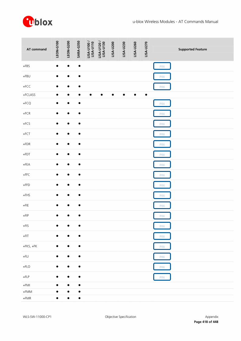
u-blox Wireless Modules - AT Commands Manual
WLS-SW-11000-CP1 Objective Specification Appendix
Page 418 of 448
AT command
LEO
N-G
100
LEO
N-G
200
SA
RA
-G350
LIS
A-U
100 /
LIS
A-U
110
LIS
A-U
120 /
LIS
A-U
130
LIS
A-U
200
LIS
A-U
230
LIS
A-U
260
LIS
A-U
270
Supported Feature
+FBS
+FBU
+FCC
+FCLASS
+FCQ
+FCR
+FCS
+FCT
+FDR
+FDT
+FEA
+FFC
+FFD
+FHS
+FIE
+FIP
+FIS
+FIT
+FKS, +FK
+FLI
+FLO
+FLP
+FMI
+FMM
+FMR
PIN
PIN
PIN
PIN
PIN
PIN
PIN
PIN
PIN
PIN
PIN
PIN
PIN
PIN
PIN
PIN
PIN
PIN
PIN
PIN
PIN

u-blox Wireless Modules - AT Commands Manual
WLS-SW-11000-CP1 Objective Specification Appendix
Page 419 of 448
AT command
LEO
N-G
100
LEO
N-G
200
SA
RA
-G350
LIS
A-U
100 /
LIS
A-U
110
LIS
A-U
120 /
LIS
A-U
130
LIS
A-U
200
LIS
A-U
230
LIS
A-U
260
LIS
A-U
270
Supported Feature
+FMS
+FND
+FNR
+FNS
+FPA
+FPI
+FPP
+FPS
+FPW
+FRQ
+FRY
+FSA
+FSP
+GCAP
+GMI
+GMM
+GMR
+GSN
+ICF
+IFC
+IPR
+PACSP
+SATD
+SATE
+SATR
+STKCTRLIND
+STKENV
PIN
PRF
PRF
PRF
PIN
PIN
PIN
PIN
PIN
PIN
PIN
PIN
PIN
PIN
PIN
PIN
PIN

u-blox Wireless Modules - AT Commands Manual
WLS-SW-11000-CP1 Objective Specification Appendix
Page 420 of 448
AT command
LEO
N-G
100
LEO
N-G
200
SA
RA
-G350
LIS
A-U
100 /
LIS
A-U
110
LIS
A-U
120 /
LIS
A-U
130
LIS
A-U
200
LIS
A-U
230
LIS
A-U
260
LIS
A-U
270
Supported Feature
+STKPRO
+STKPROF
+STKTR
+UADC
+UANTR
+UBANDSEL
+UCALLSTAT
+UCD
+UCEER
+UCELLINFO
+UCGCLASS
+UCGOPS
+UCIND
+UCLASS
+UCMGL
+UCMGP
+UCMGR
+UCMGS
+UCMGW
+UCSD
+UCSDA
+UCSND
+UCSP
+UDATACHANNEL
+UDBF
+UDCONF=0
+UDCONF=1
+UDCONF=2
PRF
NVM
NVM
ABT PIN
ABT PIN
PIN
PIN
PIN
NVM
ABT PIN
NVM
PIN
NVM
PIN
PIN
PIN

u-blox Wireless Modules - AT Commands Manual
WLS-SW-11000-CP1 Objective Specification Appendix
Page 421 of 448
AT command
LEO
N-G
100
LEO
N-G
200
SA
RA
-G350
LIS
A-U
100 /
LIS
A-U
110
LIS
A-U
120 /
LIS
A-U
130
LIS
A-U
200
LIS
A-U
230
LIS
A-U
260
LIS
A-U
270
Supported Feature
+UDCONF=3
+UDCONF=20
+UDCONF=30
+UDCONF=31
+UDCONF=32
+UDCONF=40
+UDCONF=50
+UDELFILE
+UDNSRN
+UDOPN
+UDTMF
+UDWNFILE
+UECALLSTAT
+UECALLTYPE
+UEONS
+UEXTDCONF
+UFOTA
+UFRW
+UFTP
+UFTPC
+UFTPER
+UFWUPD
+UGAOF
+UGAOP
+UGAOS
+UGCNTRD
+UGCNTSET
+UGGGA
+UGGLL
NVM
NVM
PIN
PIN
NVM
NVM
NVM
NVM
ABT PIN
NVM
NVM
PIN
NVM
NVM
NVM

u-blox Wireless Modules - AT Commands Manual
WLS-SW-11000-CP1 Objective Specification Appendix
Page 422 of 448
AT command
LEO
N-G
100
LEO
N-G
200
SA
RA
-G350
LIS
A-U
100 /
LIS
A-U
110
LIS
A-U
120 /
LIS
A-U
130
LIS
A-U
200
LIS
A-U
230
LIS
A-U
260
LIS
A-U
270
Supported Feature
+UGGSA
+UGGSV
+UGIND
+UGPIOC
+UGPIOR
+UGPIOW
+UGPRF
+UGPS
+UGRMC
+UGTMR
+UGUBX
+UGVTG
+UGZDA
+UHFP
+UHOMEZR
+UHSDUPA
+UHTTP
+UHTTPC
+UHTTPER
+UI2CC
+UI2CO
+UI2CR
+UI2CREGR
+UI2CW
+UIBMDATA
+UIBMSTAT
+UI2S
+ULOC
+ULOCCELL
+ULOCGNSS
NVM
NVM
NVM
NVM
PRF
NVM
NVM
NVM
NVM
NVM
NVM
NVM

u-blox Wireless Modules - AT Commands Manual
WLS-SW-11000-CP1 Objective Specification Appendix
Page 423 of 448
AT command
LEO
N-G
100
LEO
N-G
200
SA
RA
-G350
LIS
A-U
100 /
LIS
A-U
110
LIS
A-U
120 /
LIS
A-U
130
LIS
A-U
200
LIS
A-U
230
LIS
A-U
260
LIS
A-U
270
Supported Feature
+ULSTFILE
+UMCLK
+UMGC
+UMSM
+UMWI
+UPAR
+UPINCNT
+UPING
+UPLAYFILE
+UPROGRESS
+UPSD
+UPSDA
+UPSND
+UPSV
+URAT
+URDBLOCK
+URDFILE
+UREG
+URNG
+URXDIV
+USAPIND
+USAPMODE
+USAR
+USGC
+USIMLCK
+USMTP
+USMTPC
+USMTPER
+USMTPM
+USOCL
+USOCO
+USOCR
PRF
NVM
NVM
NVM
PRF
NVM
NVM
SIM
PRF
NVM

u-blox Wireless Modules - AT Commands Manual
WLS-SW-11000-CP1 Objective Specification Appendix
Page 424 of 448
AT command
LEO
N-G
100
LEO
N-G
200
SA
RA
-G350
LIS
A-U
100 /
LIS
A-U
110
LIS
A-U
120 /
LIS
A-U
130
LIS
A-U
200
LIS
A-U
230
LIS
A-U
260
LIS
A-U
270
Supported Feature
+USOCTL
+USODL
+USOER
+USOGO
+USOLI
+USORD
+USORF
+USOSO
+USOST
+USOWR
+USPM
+USTN
+USTOPFILE
+USTS
+UTEST
+UTGN
+UUBF
+UUICC
+UVTS
+VTD
+VTS
+WS46
A
A/
D
DL
E
H
I
L
M
O
PIN
PRF
ABT SIM
PIN
ABT PIN
PRF
PRF
PRF
NVM

u-blox Wireless Modules - AT Commands Manual
WLS-SW-11000-CP1 Objective Specification Appendix
Page 425 of 448
AT command
LEO
N-G
100
LEO
N-G
200
SA
RA
-G350
LIS
A-U
100 /
LIS
A-U
110
LIS
A-U
120 /
LIS
A-U
130
LIS
A-U
200
LIS
A-U
230
LIS
A-U
260
LIS
A-U
270
Supported Feature
P
Q
S0
S10
S12
S2
S3
S4
S5
S6
S7
S8
T
V
X
Z
PRF
PRF
PRF
PRF
PRF
PRF
PRF
PRF
PRF

u-blox Wireless Modules - AT Commands Manual
WLS-SW-11000-CP1 Objective Specification Appendix
Page 426 of 448
B.1 Parameters stored in profiles Some parameter settings can be stored in the NVRAM profiles available in the memory module. To store,
partially display, activate and de-activate these profiles, refer to AT&W (chapter 14.7), AT&V (chapter 14.8), AT&Y (chapter 14.9) command description.
Not all parameter setting are displayed through with AT&V command.
Some AT commands have a unique configuration for all AT interfaces while for other AT commands it is possible to set a different configuration for each AT interface: the “AT interface configuration sharing”
column in the next table provides this information
The following table lists the AT commands that can be stored in the profiles with their parameters as well as the
factory-programmed values.
AT command
Description AT interface configuration sharing
Factory-programmed value
6
Comment
&C DCD Status No 1 DCD enabled
&D DTR Status No 1 DTR enabled
&K Flow control status No 3 RTS/CTS DTE flow control enabled
&S DSR override No 1 DSR line set to OFF
+CBST Bearer service type (speed/ name/ connection element)
Yes 7,0,1 standard configuration for bearer service parameters:
speed: 9600 b/s
name: data circuit asynchronous
connection element: non-transparent
+CMGF Preferred message format
Yes 0 Format of messages in PDU mode
+CNMI New message indication
Yes 1,0,0,0,0 discard indication and reject new received message URCs when MT-DTE link is reserved
No SMS-DELIVER indications are routed to the TE
No CBM indications to the DTE
No SMS-STATUS-REPORTs are routed to the DTE
+COPS Operator selection Yes 0, 0, FFFF Autoregistration enabled (<mode>: 0)
Operator expressed in long alphanumeric format (<format>: 0)
PLMN to register when COPS=1 (FFFF: undefined)
+CR Reporting control status
No 0 Reporting disabled
+CRC Cellular result code status
No 0 Extended format disabled
+CRLP Radio Link protocol settings
Yes 61,61,48,6 Standard configuration for radio link protocol
IWF to MT window size: 61
MT to IWF window size: 61
acknowledgement timer: 48
retransmission attempts: 6
+ICF DTE-DCE character framing
No On LEON-G100 / LEON-G200 series
0,0
On LEON-G100 / LEON-G200 series
Framing format autodetected
6 The default value is a factory setting

u-blox Wireless Modules - AT Commands Manual
WLS-SW-11000-CP1 Objective Specification Appendix
Page 427 of 448
AT command
Description AT interface configuration sharing
Factory-programmed value
6
Comment
On (LISA-U1 / LISA-U2 series
3,1
On LISA-U1 / LISA-U2 series
Framing format: 8 data 1 stop, no parity
+IFC DTE-DCE local flow control
No 2,2 <DCE_by_DTE> on circuit 106 (CTS)
<DTE_by_DCE> on circuit 105 (RTS)
+IPR Baud rate No On LEON-G100 / LEON-G200 series:
0
On LISA-U1 series and LISA-U200-00S version:
115200
On LISA-U2 series:
0
On LEON-G100 / LEON-G200 series:
Autobauding enabled
On LISA-U1 series and LISA-U200-00S version:
115200 b/s
On LISA-U2 series:
Autobauding enabled
+UDBF Downlink Biquad Digital Filters
Yes On LEON-G100 / LEON-G200:
Path 0:
Filter1: 0, 0, 0, 0, 32767
Filter2: 0, 0, 0, 0, 32767
Path 1:
Filter1: -29322, -29141, 29322, 26240, 29322
Filter2: 29322, 29141, 29322, 26240, 29322
Path 3:
Filter1: 0, 0, 0, 0, 32767
Filter2: 0, 0, 0, 0, 32767
Path 4:
Filter1: 0, 0, 0, 0, 32767
Filter2: 0, 0, 0, 0, 32767
On LEON-G100 / LEON-G200:
Path 0:
Filter1: a1:0, b1:0, a2:0, b2:0, a0:32767
Filter2: a1:0, b1:0, a2:0, b2:0, a0:32767
Path 1:
Filter1: a1:-29322, b1:-29141, a2:29322, b2:26240, a0:29322
Filter2: a1:29322, b1:29141, a2:29322, b2:26240, a0:29322
Path 3:
Filter1: a1:0, b1:0, a2:0, b2:0, a0:32767
Filter2: a1:0, b1:0, a2:0, b2:0, a0:32767
Path 4:
Filter1: a1:0, b1:0, a2:0, b2:0, a0:32767
Filter2: a1:0, b1:0, a2:0, b2:0, a0:32767
On LISA series, for all paths, all fiters are set to: 0, 0, 0, 0, 32767
On LISA series, for all paths, all fiters are set to:
a1:0, b1:0, a2:0, b2:0, a0:32767

u-blox Wireless Modules - AT Commands Manual
WLS-SW-11000-CP1 Objective Specification Appendix
Page 428 of 448
AT command
Description AT interface configuration sharing
Factory-programmed value
6
Comment
+UHFP Hand Free Parameters
Yes On LEON-G100 / LEON-G200:
Path 0:
0x01fd, 0x016e, 2200, 250, 3, 5, 150, 0, 0, 500, 4096, 16384, 16384
Path 1:
0x01fd, 0x016e, 2200, 250, 3, 5, 150, 0, 0, 500, 4096, 16384, 16384
Path 2:
0x01fd, 0x016e, 2200, 250, 8, 5, 150, 0, 0, 500, 4096, 16384, 16384
On LEON-G100 / LEON-G200:
Path 0:
HF_algorithm_init:0x01fd, HF_Algorithm_Restart:0x016e, Step_Width:2200, LMS_Length:250, LMS_Offset:3, Block_Length:5, RXTX_Relation:150, Add_Atten:0, Min_Atten:0, Max_Atten:500, NR_sw_2:4096, NR_u_fak_0:16384, NR_u_fak:16384
Path 1:
HF_algorithm_init:0x01fd, HF_Algorithm_Restart:0x016e, Step_Width:2200, LMS_Length:250, LMS_Offset:3, Block_Length:5, RXTX_Relation:150, Add_Atten:0, Min_Atten:0, Max_Atten:500, NR_sw_2:4096, NR_u_fak_0:16384, NR_u_fak:16384
Path 2:
HF_algorithm_init:0x01fd, HF_Algorithm_Restart:0x016e, Step_Width:2200, LMS_Length:250, LMS_Offset:8, Block_Length:5, RXTX_Relation:150, Add_Atten:0, Min_Atten:0, Max_Atten:500, NR_sw_2:4096, NR_u_fak_0:16384, NR_u_fak:16384
On LISA-U120 / LISA-U130:
Paths 0, 1, 2:
0x01fd, NA,NA,NA,NA,NA,NA, 0, 0, 500, 8192, 7500, 7500, 2,100,100,100,60,60,60
Path 4:
0x01fd, NA,NA,NA,NA,NA,NA, 50, 100, 500, 8192, 7500, 7500, 2,220,220,220,60,60,60
On LISA-U120 / LISA-U130:
Paths 0, 1, 2:
HF_algorithm_init:0x01fd, HF_Algorithm_Restart:Not Available, Step_Width:Not Available, LMS_Length:Not Available, LMS_Offset:Not Available, Block_Length:Not Available, RXTX_Relation:Not Available, Add_Atten:0, Min_Atten:0, Max_Atten:500, NR_sw_2:8192, NR_u_fak_0:7500, NR_u_fak:7500, EC_block_length:2, EC_nr_coeff_real:100, EC_nr_coeff_complex1:100, EC_nr_coeff_complex2:100, EC_nr_coeff_complex3:60, EC_nr_coeff_complex4:60, EC_nr_coeff_complex5:60
Path 4:
HF_algorithm_init:0x01fd, HF_Algorithm_Restart:Not Available, Step_Width:Not Available, LMS_Length:Not Available, LMS_Offset:Not Available, Block_Length:Not Available, RXTX_Relation:Not Available,Add_Atten:50, Min_Atten:100, Max_Atten:500, NR_sw_2:8192, NR_u_fak_0:7500, NR_u_fak:7500,EC_block_length:2, EC_nr_coeff_real:220, EC_nr_coeff_complex1:220, EC_nr_coeff_complex2:220,EC_nr_coeff_complex3:60, EC_nr_coeff_complex4:60, EC_nr_coeff_complex5:60
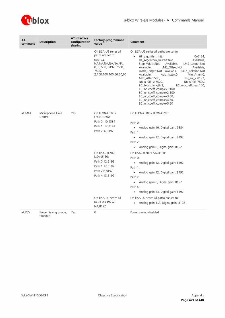
u-blox Wireless Modules - AT Commands Manual
WLS-SW-11000-CP1 Objective Specification Appendix
Page 429 of 448
AT command
Description AT interface configuration sharing
Factory-programmed value
6
Comment
On LISA-U2 series all paths are set to:
0x0124, NA,NA,NA,NA,NA,NA, 0, 0, 500, 8192, 7500, 7500, 2,100,100,100,60,60,60
On LISA-U2 series all paths are set to:
HF_algorithm_init: 0x0124, HF_Algorithm_Restart:Not Available, Step_Width:Not Available, LMS_Length:Not Available, LMS_Offset:Not Available, Block_Length:Not Available, RXTX_Relation:Not Available, Add_Atten:0, Min_Atten:0, Max_Atten:500, NR_sw_2:8192, NR_u_fak_0:7500, NR_u_fak:7500, EC_block_length:2, EC_nr_coeff_real:100, EC_nr_coeff_complex1:100, EC_nr_coeff_complex2:100, EC_nr_coeff_complex3:60, EC_nr_coeff_complex4:60, EC_nr_coeff_complex5:60
+UMGC Microphone Gain Control
Yes On LEON-G100 / LEON-G200:
Path 0: 10,9384
Path 1: 12,8192
Path 2: 6,8192
On LEON-G100 / LEON-G200:
Path 0:
Analog gain:10, Digital gain: 9384
Path 1:
Analog gain:12, Digital gain: 8192
Path 2:
Analog gain:6, Digital gain: 8192
On LISA-U120 / LISA-U130:
Path 0:12,8192
Path 1:12,8192
Path 2:6,8192
Path 4:13,8192
On LISA-U120 / LISA-U130:
Path 0:
Analog gain:12, Digital gain: 8192
Path 1:
Analog gain:12, Digital gain: 8192
Path 2:
Analog gain:6, Digital gain: 8192
Path 4:
Analog gain:13, Digital gain: 8192
On LISA-U2 series all paths are set to:
NA,8192
On LISA-U2 series all paths are set to:
Analog gain: NA, Digital gain: 8192
+UPSV Power Saving (mode, timeout)
Yes 0 Power saving disabled

u-blox Wireless Modules - AT Commands Manual
WLS-SW-11000-CP1 Objective Specification Appendix
Page 430 of 448
AT command
Description AT interface configuration sharing
Factory-programmed value
6
Comment
+USGC Speaker Gain Control
Yes On LEON-G100 / LEON-G200:
Path 0: 6, 1, 8192, 16384, 8192
Path 1: 6, 0, 8192, 16384, 10240
Path 3: 0, 6, 8192, 16384, 8191
Path 4: 6, 6, 8192, 16384, 8191
On LEON-G100 / LEON-G200:
Path 0:
Speaker gain: 6, Headset gain: 1, speech and Tone Generator gain: 8192, Synthesizers gain: 16384, Speech gain: 8192
Path 1:
Speaker gain:6, Headset gain:0, speech and Tone Generator gain: 8192, Synthesizers gain: 16384, Speech gain:10240
Path 3:
Speaker gain: 0, Headset gain: 6, speech and Tone Generator gain: 8192, Synthesizers gain:16384, Speech gain: 8191
Path 4:
Speaker gain: 6, Headset gain: 6, speech and Tone Generator gain: 8192, Synthesizers gain: 16384, Speech gain: 8191
On LISA-U120 / LISA-U130:
Path 0:
NA,0,8192,16384,NA
Path 1:
NA,1,8192,16384,NA
Path 3:
NA,0,8192,16384,NA
Path 4:
NA,3,8192,16384,NA
On LISA-U120 / LISA-U130:
Path 0:
Speaker gain: Not Available, Headset gain: 0, speech and Tone Generator gain: 8192, Synthesizers gain: 16384, Speech gain: Not Available
Path 1:
Speaker gain: Not Available, Headset gain1, speech and Tone Generator gain: 8192, Synthesizers gain: 16384, Speech gain: Not Available
Path 3:
Speaker gain: Not Available, Headset gain: 0, speech and Tone Generator gain: 8192, Synthesizers gain: 16384, Speech gain: Not Available
Path 4:
Speaker gain: Not Available, Headset gain: 3, speech and Tone Generator gain: 8192, Synthesizers gain: 16384, Speech gain: Not Available
On LISA-U2 series all paths are set to:
NA,NA,8192,16384,NA
On LISA-U2 series all paths are set to:
Speaker gain: Not Available,
Headset gain: Not Available,
speech and Tone Generator gain: 8192,
Synthesizers gain: 16384,
Speech gain: Not Available
+USTS Smart Temperature Supervisor
Yes 0 Smart temperature URC disabled

u-blox Wireless Modules - AT Commands Manual
WLS-SW-11000-CP1 Objective Specification Appendix
Page 431 of 448
AT command
Description AT interface configuration sharing
Factory-programmed value
6
Comment
+USTN Sidetone Yes On LEON-G100 / LEON-G200:
Path 0: 2249
Path 1: 2249
Path 3: 0
Path 4: 0
On LEON-G100 / LEON-G200:
Path 0:
Gain for side tone: 2249
Path 1:
Gain for side tone: 2249
Path 3:
Gain for side tone: 0
Path 4:
Gain for side tone: 0
On LISA-U120 / LISA-U130:
Path 0: 512
Path 1: 512
Path 3: 0
Path 4: 0
On LISA-U120 / LISA-U130:
Path 0:
Gain for side tone: 512
Path 1:
Gain for side tone: 512
Path 3:
Gain for side tone: 0
Path 4:
Gain for side tone: 0
On LISA-U2 series all paths are set to 512
On LISA-U2 series, for all paths:
Gain for side tone: 512
+UUBF Uplink Digital Filters (Uplink Biquad Filters)
Yes On LEON-G100 / LEON-G200:
Path 0:
Filter1: -13915, 2249, 4377, -325, 23450
Filter2: 21682, -2312, 17984, -15517, 32767
Path 1:
Filter1: -29322, -29141, 29322, 26240, 29322
Filter2: 29322, 29141, 29322, 26240, 29322
Path 2:
Filter1: 0, 0, 0, 0, 32767
Filter2: 0, 0, 0, 0, 32767
On LEON-G100 / LEON-G200:
Path 0:
Filter1: a1:-13915, b1:2249, a2:4377, b2:-325, a0:23450
Filter2: a1:21682, b1:-2312, a2:17984, b2:-15517, a0:32767
Path 1:
Filter1: a1:-29322, b1:-29141, a2:29322, b2:26240, a0:29322
Filter2: a1:29322, b1:29141, a2:29322, b2:26240, a0:29322
Path 2:
Filter1: a1:0, b1:0, a2:0, b2:0, a0:32767
Filter2: a1:0, b1:0, a2:0, b2:0, a0:32767
On LISA series, for all paths, all fiters are set to: 0, 0, 0, 0, 32767
On LISA series, for all paths, all fiters are set to:
a1:0, b1:0, a2:0, b2:0, a0:32767
E Echo status No 1 Echo enabled
Q Result code suppression
No 0 DCE transmits result codes
S0 Automatic answer No 0 Automatic answering disabled
S2 Escape character selection
No 43 043 corresponds the ‘+’ character

u-blox Wireless Modules - AT Commands Manual
WLS-SW-11000-CP1 Objective Specification Appendix
Page 432 of 448
AT command
Description AT interface configuration sharing
Factory-programmed value
6
Comment
S3 Command line termination character
No 13 0x0d corresponds to the carriage return character
S4 Response formatting character
No 10 0x0a corresponds to the line feed character
S5 Command line editing character
No 8 008 corresponds to the backspace character
S7 Connection completion timeout
No 60
V DCE Response format
No 1 Verbose response text
X Result code selection and call progress monitoring control
No 4 CONNECT <text> result code is given upon entering online data state; dial tone and busy detection are both enabled
B.2 Parameters stored in non volatile memory The following table lists the AT commands that can be stored in the non volatile memory with their parameters and the factory-programmed values.
AT command Description Factory-programmed value Comment
&Y Designate a default reset profile 0 Profile 0 selected
+CALA Alarm No alarms are stored
+CALM Alert sound mode 0 Mute disabled
+CCLK Clock 04/01/01,00:00:00+00
+CGDCONT PDP Context definition All contexts are undefined Not available in LEON-G100 / LEON-G200 series
The 3 PDP contexts are permanently stored when they are defined or deleted
+CGSMS Select service for MO SMS messages
1 CSD service enabled
+CLVL Speech volume level 80 80
+CPMS Preferred message storage "MT", "MT", "MT" <mem1>, <mem2> and <mem3> are set to "MT"="ME"+"SM" with "ME" preferred
+CRSL Ringer sound level 4 Ringer sound level: 4
+CSAS Save settings 0 Profile 0 where to store the active message settings
+CSCA Service center address "" Service center address set empty
+CSCB Select cell broadcast message types
0, "", "" Accepted the message types specified in <mids> and <dcss>
+CSGT Set greeting text "" Greeting text is empty
+CSMP Set text mode parameters 17, 167, 0, 0 First octet is SMS-SUBMIT
<fo>=17
<vp>=167
<pid>=0
<dcs>=0

u-blox Wireless Modules - AT Commands Manual
WLS-SW-11000-CP1 Objective Specification Appendix
Page 433 of 448
AT command Description Factory-programmed value Comment
+UCGCLASS Changing the startup MS class "B" <class>="B"
+UCLASS Device class setting LEON-G100 / LEON-G200: 10
LISA-U1 / LISA-U2: 12
LEON-G100 / LEON-G200 series: GPRS class 10
LISA-U1 / LISA-U2 series: GPRS class 12
+UCSD Circuit Switched Data Empty profile
+UDCONF=20 SoR Steering of Roaming 0 0 means SoR is disabled.
Not supported by LEON-G100-06x / LEON-G200-06x series and earlier versions, nor by LISA-U1 series and LISA-U200-00S versions
+UDCONF=30 Speech codec configuration 31 Not supported by LEON-G100-06x / LEON-G200-06x and earlier versions, nor by LISA-U1 series and LISA-U200-00S version
+UDCONF=32 Connection type groups enable/disable
127 Not supported by LEON-G100 / LEON-G200 series or by LISA-U1 series or by LISA-U200-00S version
+UDCONF=40 User defined power reduction 2,2 MSPR GPRS and EDGE profile.
Not supported by LEON-G100-06x / LEON-G200-06x and earlier versions, nor by LISA-U1 series and LISA-U200-00S version
+UDCONF=50 SIM hot insertion detection 0 Disabled
+UDTMF User setting for proactive DTMF tone generation
1 Proactive DTMF tone generation available
+UECALLSTAT eCall status 0: eCall without registration restriction
Use to select eCall Only mode or eCall without registration restriction
+UEXTDCONF Automatic configuration of the Maxim MAX9860 audio codec
0 (disabled) Not supported on LEON-G100 / LEON-G200 series and on LISA-U1 series or by LISA-U200-00S version
+UGAOF AssistNow Offline configuration "http://alp.u-blox.com/current_14d.alp",0,1,3
AssistNow Offline URL file: http://alp.u-blox.com/current_14d.alp
One minute of timeout after a fail download
Three attempts in case of failed download
+UGAOP AssistNow Online configuration "eval1-les.services.u-blox.com", 46434,1000,0
Host name server: “eval1-les.services.u-blox.com”
server port: 46434
expected network latency: 1000 ms
AssistNow Online data downloaded at GPS receiver power up
+UGGGA Get GPS fix data 0 NMEA $GGA messages disabled
+UGGLL Get geographic position 0 NMEA $GLL messages disabled
+UGGSA Get satellite information 0 NMEA $GSA messages disabled
+UGGSV Get number of GNSS satellites in view
0 NMEA $GSV messages disabled
+UGRMC Get recommended minimum GNSS data
0 NMEA $RMC messages disabled
+UGPIOC GPIO functionality setting 255 Default setting for <gpio1>, <gpio2>, <gpio3>, <gpio4>, <gpio5> at the first power up. All the GPIOs are in tristate.
+UFOTA FOTA Configuration 0, 1, 0, "" <enable>= 0
<attempts>=1
<configuration>=0
<code>=""

u-blox Wireless Modules - AT Commands Manual
WLS-SW-11000-CP1 Objective Specification Appendix
Page 434 of 448
AT command Description Factory-programmed value Comment
+UGVTG Get course over ground and ground speed
0 NMEA $VTG messages disabled
+UGZDA Get GPS Time and date 0 NMEA $ZDA messages disabled
+UGPRF 0, 0, "" No data flow on multiplexer, file and IP address
IP port not defined
Server address string not defined
+UI2S I2S Digital Interface Mode On LEON-G100 / LEON-G200
series: 4,2,1
On LISA-U120 / LISA-U130: 0,1,0,0,0
On LISA-U2 series
1,1,0,3,0
1,3,0,3,0
On LEON-G100 / LEON-G200 series:
I2S mode: normal mode 4
I2S port: I2Sy
I2S_CLK and I2S_WA signals are active in continuous mode
On LISA-U120 / LISA-U130:
I2S mode: PCM mode 0
I2S port: I2Sx
I2S_CLK and I2S_WA signals are active in dynamic mode
I2S sample rate: 8 kHz
I2S Master Slave mode: Master
On LISA-U2 series:
I2S mode: PCM mode 1
I2S port: I2S is connected to I2Sx
connection point
I2S_CLK and I2S_WA signals are active in dynamic mode
I2S sample rate: 16 kHz
I2S Master Slave mode: Master
I2S mode: PCM mode 1
I2S1 port: I2S1 is connected to I2Sx connection point
I2S1_CLK and I2S1_WA signals are active in dynamic mode
I2S1 sample rate: 16 kHz
I2S1 Master Slave mode: Master
+ULOCCELL Configure cellular location sensor (CellLocate)
0 Normal mode enabled
+ULOCGNSS Configure GNSS sensor 15,0,3,7,0,0,0,0,0,0,0,0,0,0 Local aiding, AssistNow online, AssistNow offline, AssistNow autonomous enabled
Power saving disabled
Minimum number of satellites for navigation: 3
Minimum satellite signal level for navigation: 7
Disabled initial Fix must be 3D flag
Static Hold Mode: 0
SBAS disabled
Jamming indicator disabled
Antenna settings unknown
Broadband jamming detection threshold: 0 dB
Continuous wave jamming detection threshold: 0 dB

u-blox Wireless Modules - AT Commands Manual
WLS-SW-11000-CP1 Objective Specification Appendix
Page 435 of 448
AT command Description Factory-programmed value Comment
+UMCLK Master Clock Control 0 CODEC_CLK mode setting (<mclk_mode>): clock out pin from LISA module (input for audio codec) is set as three state with pull down resistor.
0 Setting of dynamic of the application mode (<enabling_mode>): <mclk_mode> setting is applied to CODEC_CLK pin only when audio path is active. After audio path is disabled (i.e. a call is hang up) CODEC_CLK is disabled too
+UPSD Packet Switched Data Empty profile
+URAT Selection of Radio Access technology
1,2 Radio Access technology: GSM/UMTS Dual mode
RAT UMTS
+URNG Ringing tone selection 0 Melody 0
+URXDIV RX Diversity 1 3G Rx Diversity disabled
DARP Phase 3 DARP Phase 2 always on
+USPM Audio Path mode setting On LEON-G100/LEON-G200 series: 0,0,1,1,0
On LEON-G100/LEON-G200 series:
Speech audio output path: Handset microphone
Speech audio input path: Normal earpiece
Alert sound on Loudspeaker
Headset indication: considered
VMIC is switched On /Off
On LISA-U1 / LISA-U2 series:
1,1,0,0,2
On LISA-U1 / LISA-U2 series:
Speech audio output path: Headset microphone
Speech audio input path: Mono headset earpiece
Alert sound on main downlink path (Mono headset earpiece)
Headset indication: not considered
VMIC is always switched Off

u-blox Wireless Modules - AT Commands Manual
WLS-SW-11000-CP1 Objective Specification Appendix
Page 436 of 448
B.3 Saving AT commands configuration The following procedure can be used to store the AT commands configuration for the AT commands listed in
chapter B.1 and B.2.
Write the run-time configuration of the active AT interface to the RAM profile mirror with the AT&W
command (e.g. AT&W0; more details in chapter 14.7)
Confirm that boot loading is performed with the desired parameter profile (e.g. profile 0 if the parameter
save was performed with AT&W0; use AT&Y0 to select this)
Save the RAM profile mirror and the non-profile AT commands configuration (refer to chapter B.1) to NVRAM memory with the AT+CPWROFF command
Perform a reboot/PWR_ON reset of the device
The last two steps can also be performed with the AT command AT+CFUN=15 (switches off and reboots the
device).
B.4 Estimated command response time After having sent a command to a u-blox wireless module, the time to obtain a resulting response depends on the SIM and the network. It is possible to have an immediate response if the command doesn't interact with
either the network or the SIM.
The following table reports the maximum time to get the response for the AT commands that perform a network scan or read the SIM card. The commands are grouped by categories.
Category Estimated maximum time to get response
Commands
Call control and Supplementary services
< 20 s +VTS, A, H, +CHLD, +CHUP, +CNAP, +COLP, +COLR
Power Off < 20 s +CPWROFF
Profile management < 20 s ATZ
Network commands Up to 3 min (<1 s for prompt ">" when present)
+CCFC, +CCWA, +CLCK, +CLIP, +CLIR, +CPWD, +CTFR, +CUSD, +UCGOPS, D, +CFUN, +CMSS, +CMGS, +CGDATA, +CGACT, +CGATT, Data connect, +COPS
SIM management < 10 s +CRES, +CACM, +CAMM, +CNUM, +CPIN, +CPOL, +CPUC, +CRSM
SIM toolkit < 20 s +STKPRO, +STKENV, +STKTR
GPS commands < 10 s (except +UGPS for which timeout is according to the performed operation)
+UGAOP, +UGAOS, +UGGGA, +UGGLL, +UGGSA, +UGGSV, +UGPRF, +UGPS, +UGRMC, +UGTMR, +UGUBX, +UGVTG, +UGZDA, +ULOC, +ULOCCELL, +ULOCGNSS
GPIO commands < 10 s +UGPIOC, +UGPIOR, +UGPIOW
Internet suite (TCP/IP, DNS, FTP, HTTP, SMTP)
< 10 s (except URC) +USOCR, +USOSO, +USOGO, +USOCL, +USOER, +USOCO, +USOWR, +USOST, +USORD, +USORF, +USOLI, +UFRW, +USODL, +USOCTL, +UDNSRN, +UFTP,+UFTPC,+UFTPER, +UHTTP, +UHTTPC, +UHTTPER, +USMTP, +USMTPM, +USMTPC, +USMTPER
Phonebook commands < 20 s +CPBS, +CPBR, +CPBF, +CPBW
PDP Context Activation < 150 s +UPSDA, +CGACT
PDP Context Deactivation
< 40 s +UPSDA, +CGACT

u-blox Wireless Modules - AT Commands Manual
WLS-SW-11000-CP1 Objective Specification Appendix
Page 437 of 448
B.5 Multiple AT command interfaces Both LEON-G100 / LEON-G200 and LISA-U1 series support multiple AT command interfaces, that means a
certain number of virtual or physical channels (LEON-G100 / LEON-G200 has only one physical interface (UART), the others are virtual interfaces implemented via the multiplexer protocol) that work as described in chapter 1.1.
Each interface maintains an own run-time AT commands configuration (AT command profile); this means that
the AT command profile is different amongs the interfaces and therefore the AT commands configuration for the commands belonging to the profile can be different among the interfaces.
At start-up, since there is only a set of NVRAM profiles (not one for each interface), all the interfaces are
configured in the same way (AT commands configuration for the commands in the profile is the same for all the interfaces). Subsequentelly, each interface can change its run-time AT profile (stored in RAM). The commands
AT&W (chapter 14.7), AT&V (chapter 14.8) manage this run-time AT commands configuration for the interface
where they are issued.
As mentioned in chapter 1.1, generally there is not difference in the execution of an AT command among the
interfaces. But, there are some exceptions due to interface restrictions. In particular, the differences are related
to the AT commands that configure the DCE-DTE interface.
Major differences are reported in Table 23.
AT command UART Multiplexer USB (where available) SPI (where available)
AT&K Effective When allowed it is effective When allowed, it returns OK but it is not effective
When allowed, it returns OK but it is not effective
AT\Q Effective When allowed it is effective When allowed, it returns OK but it is not effective
When allowed, it returns OK but it is not effective
AT+IFC Effective When allowed it is effective When allowed, it returns OK but it is not effective
When allowed, it returns OK but it is not effective
AT+IPR Effective Returns OK but it is not effective
Returns OK but it is not effective
Returns OK but it is not effective
AT+ICF Effective Returns OK but it is not effective
Returns OK but it is not effective
Returns OK but it is not effective
AT+UPSV Effective Returns OK but it changes UART setting
Returns OK but it changes UART setting
Returns OK but it changes UART setting
Table 23: Interface comparison

u-blox Wireless Modules - AT Commands Manual
WLS-SW-11000-CP1 Objective Specification Appendix
Page 438 of 448
C UDP Direct Link workflow
C.1 Data from the IP network to the external port When an UDP data packet is received from the network, its payload is forwarded through the external port as
soon as possible (according to the HW flow control, if any).
Data from IP network
Forward it to external port
(according with HW flow control, if any)
C.2 Data from the external port to the IP network When some data comes from the external port, there are 2 parameters involved:
1. The UDP DL packet size (factory-programmed: 1024 bytes; valid range 100-1472) 2. The UDP DL sending timer delay (factory-programmed: 1000 ms; valid range 100-120000)
Both parameters are specific for each socket and could be modified by the user. These values are not saved into the NVM and if not specified, the factory-programmed values are used.
There are 3 different cases that may occur while receiving data from the external port in UDP DL mode:
A) The received data from the external port is equal to the UDP DL packet size
B) The received data from the external port is more than the UDP DL packet size C) The received data from the external port is less than UDP DL packet size
Case A: the received data is immediately sent to the network
Case B: the amount of data till UDP DL packet size is immediately sent to the network, the remaining data is
saved into an intermediate buffer.
Case C: the received data is saved into an intermediate buffer and sent to the network when the UDP DL sending timer expires. The timer is reset (it restarts the countdown) every time new data is received from the
external port, this means that the data will be sent to the network after N ms (default 1000 ms) since the last
received byte.

u-blox Wireless Modules - AT Commands Manual
WLS-SW-11000-CP1 Objective Specification Appendix
Page 439 of 448
The data sent from the serial port is not echoed to the sender.
The configuration of UDP DL packet size and UDP DL sending timer are NOT saved in NVM.
The following diagram shows how the events of external data input and sending timer expire are handled.
Event: sending
timer expires
New data + data into intermediate
bufferis < than
max_packet_size?
Reset sending timer
Put data into
intermediate
buffer and
wait sending
timer expires
or new data
YES
Send max_packet_size
of data to IP network
Remaining
data
is >= max
packet size?
YES NO
Event: new
data from
external port
Is there any datainto the intermediate
buffer?
Is there
any
data?
Finish,
event
handled
YES
NO
Finish,
event
handled
Reschedule
timer
NO
YESSend data to IP
network
NO
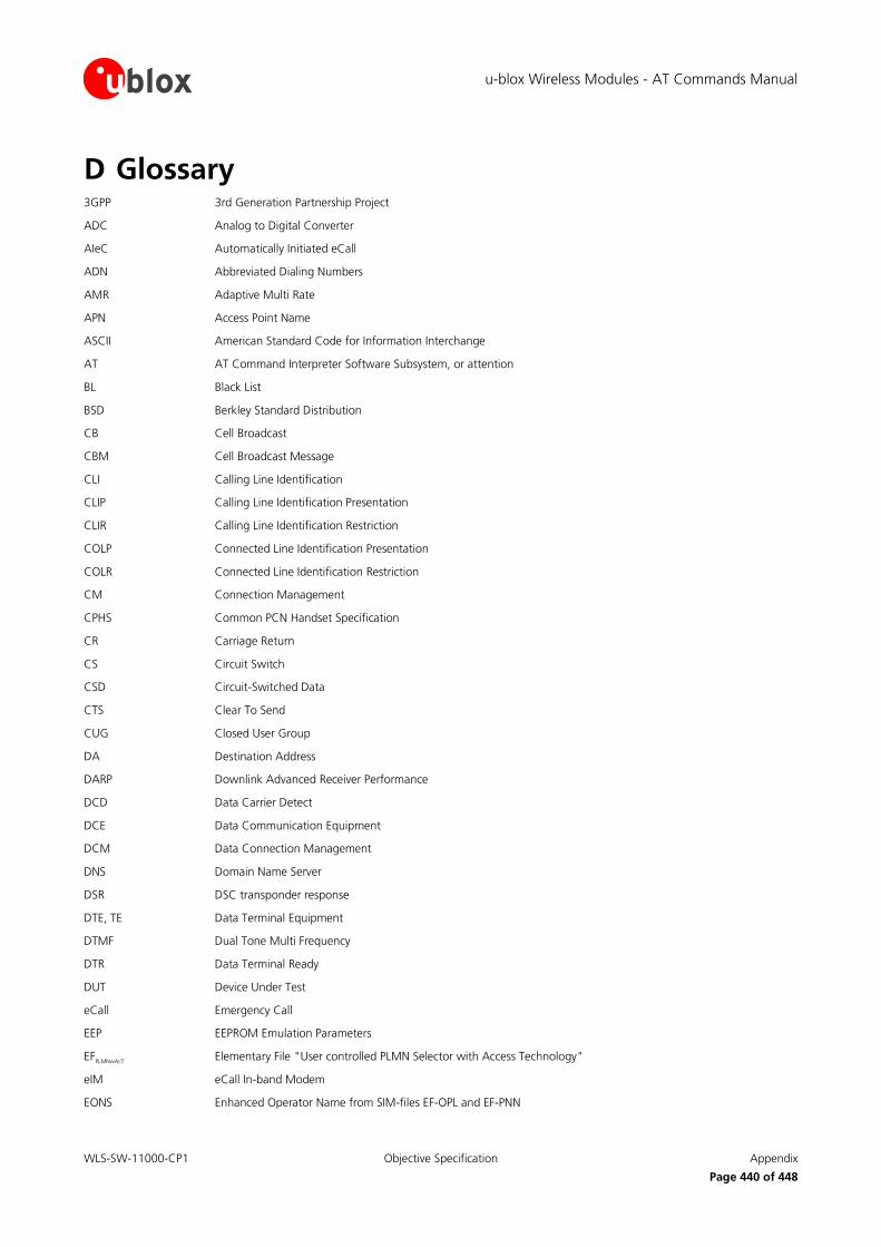
u-blox Wireless Modules - AT Commands Manual
WLS-SW-11000-CP1 Objective Specification Appendix
Page 440 of 448
D Glossary 3GPP 3rd Generation Partnership Project
ADC Analog to Digital Converter
AIeC Automatically Initiated eCall
ADN Abbreviated Dialing Numbers
AMR Adaptive Multi Rate
APN Access Point Name
ASCII American Standard Code for Information Interchange
AT AT Command Interpreter Software Subsystem, or attention
BL Black List
BSD Berkley Standard Distribution
CB Cell Broadcast
CBM Cell Broadcast Message
CLI Calling Line Identification
CLIP Calling Line Identification Presentation
CLIR Calling Line Identification Restriction
COLP Connected Line Identification Presentation
COLR Connected Line Identification Restriction
CM Connection Management
CPHS Common PCN Handset Specification
CR Carriage Return
CS Circuit Switch
CSD Circuit-Switched Data
CTS Clear To Send
CUG Closed User Group
DA Destination Address
DARP Downlink Advanced Receiver Performance
DCD Data Carrier Detect
DCE Data Communication Equipment
DCM Data Connection Management
DNS Domain Name Server
DSR DSC transponder response
DTE, TE Data Terminal Equipment
DTMF Dual Tone Multi Frequency
DTR Data Terminal Ready
DUT Device Under Test
eCall Emergency Call
EEP EEPROM Emulation Parameters
EFPLMNwAcT
Elementary File "User controlled PLMN Selector with Access Technology"
eIM eCall In-band Modem
EONS Enhanced Operator Name from SIM-files EF-OPL and EF-PNN

u-blox Wireless Modules - AT Commands Manual
WLS-SW-11000-CP1 Objective Specification Appendix
Page 441 of 448
EPD Escape Prompt Delay
ETSI European Telecommunications Standards Institute
FDN Fixed Dialling Number
FFS Flash File System
FOAT Firmware Over AT
FOTA Firmware Over The Air
FTP File Transfer Protocol
FW Firmware
GPIO General Purpose Input Output
GPRS General Packet Radio Service
GPS Global Positioning System
GSM Global System for Mobile Communications
HDLC High Level Data Link Control
HPLMN Home PLMN
HTTP HyperText Transfer Protocol
I Information
I2C or I2C Inter-Integrated Circuit
I2S or I2S Inter IC Sound or Integrated Interchip Sound
ICCID Integrated Circuit Card ID
ICMP Internet Control Message Protocol
ICP Inter Processor Communication
IMEI International Mobile Equipment Identity
IMSI International Mobile Station Identity
InBM In-Band Modem (generic)
IP Internet Protocol
IRA International Reference Alphabet
IRC Intermediate Result Code
ISDN Integrated Services Digital Network
ISP Internet Service Provider
IVS In-Vehicle System (eCall related)
L3 Layer 3
LCP Link Control Protocol
LF Line Feed
M2M Machine-To-Machine
MCC Mobile Country Code
ME Mobile Equipment
MIeC Manually Initiated eCall
MMI Man Machine Interface
MN Mobile Network Software Subsystem
MNC Mobile Network Code
MO Mobile Originated
MS Mobile Station

u-blox Wireless Modules - AT Commands Manual
WLS-SW-11000-CP1 Objective Specification Appendix
Page 442 of 448
MSD Minimum Set of Data (eCall related)
MSIN Mobile Subscriber Identification Number
MSISDN Mobile Systems International Subscriber Identity Number
MSPR Multi-Slot Power Reduction
MT Mobile Terminated
MWI Message Waiting Indication
NITZ Network Identity and Time Zone
NVM Non-Volatile Memory
NVRAM Not Volatile RAM
OLCM On Line Commands Mode
PAD Packet Assembler/Disassembler
PCN Personal Communication Network
PDP Packet Data Protocol
PDU Protocol Data Unit
PIN Personal Identification Number
PLMN Public Land Mobile Network
PPP Point-to-Point Protocol
PSAP Public Safety Answering Point (eCall related)
PSD Packet-Switched Data
PUK Personal Unblocking Key
QoS Quality of Service
RAM Random Access Memory
RDI Restricted Digital Information
RFU Reserved for Future Use
RI Ring Indicator
RTC Real Time Clock
RTP Real-time Transport Protocol
RTS Request To Send
Rx Receiver
SAP SIM Access Profile
SC Service Centre
SI SIM Application Part Software Subsystem
SIP Session Initiation Protocol
SIM Subscriber Identity Module
SMS Short Message Service
SMSC Short Message Service Center
SMTP Simple Mail Transfer Protocol
SoR Steering of Roaming
TA Terminal Adaptor
TCP Transfer Control Protocol
TE Terminal Equipment
TFT Traffic Flow Template

u-blox Wireless Modules - AT Commands Manual
WLS-SW-11000-CP1 Objective Specification Appendix
Page 443 of 448
TP Transfer layer Protocol
Tx Transmitter
TZ Time Zone
UCS2 Universal Character Set
UDI Unrestricted Digital Information
UDP User Datagram Protocol
UI Unnumbered Information
UIH Unnumbered Information with header Check
URC Unsolicited Result Code
USIM UMTS Subscriber Identity Module
UUS1 User-to-User Signalling Supplementary Service 1

u-blox Wireless Modules - AT Commands Manual
WLS-SW-11000-CP1 Objective Specification Related documents
Page 444 of 448
Related documents [1] Stevens. TCP/IP Illustrated Volume1 & 2 Addison-Wesley, 1994.
[2] 3GPP TS 27.007 - Technical Specification Group Core Network and Terminals; AT command set for User Equipment (UE)
[3] 3GPP TS 22.004 - General on supplementary services
[4] GSM 02.04 - Digital cellular telecommunication system (Phase 2+); Mobile Stations (MS) features
[5] 3GPP TS 22.030 - Man-Machine Interface (MMI) of the User Equipment (UE)
[6] 3GPP TS 22.090 - Unstructured Supplementary Service Data (USSD); Stage 1
[7] 3GPP TS 23.038 - Alphabets and language-specific information
[8] 3GPP TS 23.040 - Technical realization of Short Message Service (SMS)
[9] 3GPP TS 23.041 - Technical realization of Cell Broadcast Service (CBS)
[10] 3GPP TS 23.060 - Technical Specification Group Services and System Aspects; General Packet Radio Service (GPRS); Service description
[11] 3GPP TS 24.007 - Mobile radio interface signalling layer 3; General aspects
[12] 3GPP TS 24.008 - Mobile radio interface layer 3 specification
[13] 3GPP TS 24.011 - Point-to-point (PP) Short Message Service (SMS) support on mobile radio interface
[14] GSM 04.12 - Digital cellular telecommunications system (Phase 2+); Short Message Service Cell
Broadcast (SMSCB) Support on Mobile Radio Interface.
[15] 3GPP TS 22.030 - Digital cellular telecommunications system (Phase 2+); Universal Mobile
Telecommunications System (UMTS); Man-Machine Interface (MMI) of the User Equipment (UE)
[16] 3GPP TS 27.005 - Technical Specification Group Terminals; Use of Data Terminal Equipment - Data Circuit terminating Equipment (DTE-DCE) interface for Short Message Services (SMS) and Cell
Broadcast Service (CBS)
[17] 3GPP TS 27.060 - Technical Specification Group Core Network; Packet Domain; Mobile Station (MS) supporting Packet Switched Services
[18] GSM 11.11 - Digital cellular telecommunications system (Phase 2+); Specification of the Subscriber
Identity Module – Mobile Equipment (SIM – ME) interface
[19] 3GPP TS 31.102 - Characteristics of the Universal Subscriber Identity Module (USIM) application
[20] ITU-T Recommendation V250, 05-99.
[21] ITU-T V.25ter - ITU-T V.25 ter Recommendation: Data Communications over the Telephone Network; Serial asynchronous automatic Dialling and control.
[22] ITU-T T.32 - ITU-T Recommendation T.32 Asynchronous Facsimile DCE Control - Service Class 2
[23] ISO 639 (1988) Code for the representation of names of languages
[24] LEON-G100/G200 Datasheet Docu No GSM.G1-HW-10004
[25] LEON-G100/G200 System Integration Manual Docu No GSM.G1-HW-09002
[26] ITU-T Recommendation V24, 02-2000. List of definitions for interchange circuits between Data Terminal Equipment (DTE) and Data Connection Equipment (DCE).
[27] RFC 791 - Internet Protocol - http://www.ietf.org/rfc/rfc791.txt
[28] 3GPP TS 05.08 - Radio subsystem link control
[29] 3GPP TS 22.087 - User-to-User Signalling (UUS)
[30] 3GPP TS 24.008 - Mobile radio interface layer 3 specification
[31] 3GPP TS 22.022 - Personalisation of Mobile Equipment (ME)
[32] 3GPP TS 22.082 - Call Forwarding (CF) supplementary services
[33] 3GPP TS 22.083 - Call Waiting (CW) and Call Holding (HOLD)
[34] 3GPP TS 22.081 - Line identification Supplementary Services- Stage 1

u-blox Wireless Modules - AT Commands Manual
WLS-SW-11000-CP1 Objective Specification Related documents
Page 445 of 448
[35] 3GPP TS 23.081 - Line identification supplementary services- Stage 2
[36] 3GPP TS 22.086 - Advice of Charge (AoC) Supplementary Services
[37] 3GPP TS 22.024 - Description of Charge Advice Information (CAI)
[38] 3GPP TS 22.085 - Closed User Group (CUG) Supplementary Services
[39] 3GPP TS 22.096 - Name identification supplementary services
[40] 3GPP TS 04.18 - Mobile radio interface layer 3 specification; Radio Resource Control (RRC) protocol
[41] 3GPP TS 04.60 - General Packet Radio Service (GPRS); Mobile Station (MS) - Base Station System (BSS) interface; Radio Link Control/ Medium Access Control (RLC/MAC) protocol
[42] 3GPP TS 05.02 - Multiplexing and Multiple Access on the Radio Path
[43] EVK-G25H Evaluation Kit Getting Started Docu No. GSM.G1-EK-09022
[44] 3GPP TS 51.014 - Specification of the SIM Application Toolkit for the Subscriber Identity Module -
Mobile Equipment (SIM - ME) interface
[45] u-blox 5/6 Receiver Description including Protocol Specification, Docu. No GPS-SW-09017
[46] 3GPP TS 27.010 V3.4.0 - Terminal Equipment to User Equipment (TE-UE) multiplexer protocol (Release
1999)
[47] LEON Audio Application Note Docu No. GSM.G1-CS-10005
[48] EVK-U12 EVK-U13 Getting Started Docu No. 3G.G2-EK-10010
[49] LISA-U series System Integration Manual Docu No 3G.G2-HW-10002
[50] ETSI TS 102 221 - Smart Cards; UICC-Terminal interface; Physical and logical characteristics (Release 6)
[51] ETSI TS 102 223 - Smart cards; Card Application Toolkit (CAT)
[52] GPS Implementation Application Note, Docu No GSM.G1-CS-09007
[53] 3GPP TS 25.306 - UE Radio Access capabilities
[54] RFC3267 - Real-Time Transport Protocol (RTP) Payload Format and File Storage Format for the Adaptive
Multi-Rate (AMR) and Adaptive Multi-Rate Wideband (AMR-WB) Audio Codecs
[55] EVK-G20 Evaluation Kit Getting Started Docu No. GSM.G1-EK-11002
[56] LISA-U1 series Data sheet Docu No 3G.G2-HW-10001
[57] RFC 792 Internet Control Message Protocol (http://tools.ietf.org/html/rfc0792)
[58] 3GPP TS 22.002 - Circuit Bearer Services (BS) supported by a Public Land Mobile Network (PLMN)
[59] 3GPP TS 22.067 - enhanced Multi Level Precedence and Pre-emption service (eMLPP); Stage 1
[60] LISA-U2 series Data sheet Docu No 3G.G3-HW-11004
[61] AT&T: Device Requirements -- Requirements Document -- Document Number 13340 -- Revision 4.6 -- Revision Date 9/2/11
[62] 3GPP TS 23.972 - Circuit switched multimedia telephony
[63] 3GPP TS 26.267 - Technical Specification Group Services and System Aspects; eCall Data Transfer; In-band modem solution; General description
[64] 3GPP TS 25.101 - User Equipment (UE) radio transmission and reception (FDD)
[65] 3GPP TS 45.005 - Radio transmission and reception
[66] Common PCN Handset Specification v4.2
[67] SIM Access Profile – Interoperability Specification – Bluetooth Specification V11r00
[68] EVK-U20 EVK-U23 Getting Started Docu No. 3G.G3-EK-11002
[69] Maxim MAX9860 16-Bit Mono Audio Voice Codec datasheet, 19-4349; Rev 1; 9/09. Available from
the Maxim website (http://datasheets.maxim-ic.com/en/ds/MAX9860.pdf)
[70] 3GPP TS 23.122 - NAS Functions related to Mobile Station (MS) in idle mode
[71] SARA-G3 series System Integration Manual Docu No GSM.G2-HW-12003
[72] 3GPP TS 02.60 - General Packet Radio Service Stage 1 Description
u-blox Wireless Modules - AT Commands Manual
WLS-SW-11000-CP1 Objective Specification Related documents
Page 446 of 448
[73] EVK-G35 Getting Started Docu No. GSM.G2-EK-12001
[74] SARA-G3 Series Data Sheet, Docu No GSM.G2-HW-12001
For regular updates to u-blox documentation and to receive product change notifications, register on
our homepage.

u-blox Wireless Modules - AT Commands Manual
WLS-SW-11000-CP1 Objective Specification Revision history
Page 447 of 448
Revision history Revision Date Name Status / Comments
- Apr. 30, 2011 tgri Initial release
P1 May. 06, 2011 lpah Changed the title, removed “2G and 3.75G”
1 May. 11, 2011 lpah New commands for LEON-06x supported
2 May. 26, 2011 lpah Improvement for GPS and GPIO AT commands
3 Jul. 07, 2011 lpah Assistnow online and offline description in +ULOCGNSS corrected
Changed status to Preliminary
A Oct. 14, 2011 lpah Applicable to LISA-U1x0-01S and LISA-U200-00S
Added commands for STK raw mode and +PACSP
A1 Dec. 05, 2011 mtom / lpah Changed status to Advance Information
Improved the +UVTS command syntax
+CGDCONT setting stored in non volatile memory
Improved the primary and secondary PDP contexts description
New settings for the FW update over AT commands
Added number of allowed SIM locks
A2 Feb. 03, 2012 mtom / lpah Changed status to Preliminary
B May. 18, 2012 mtom / lpah Changed status to Objective Specification status
Extended audio AT commands for LISA-U200-01 and LISA-U230-01
Added description for +UCMGP, +UMCLK, +URXDIV, +UMWI I2C and SAP AT
commands
Extended applicability to LEON-G100-07
B1 Jul. 31, 2012 mtom Changed status to Preliminary
Added +UEXTDCONF command description and one shot automatic baud rate detection description
B2 Oct. 10, 2012 lpah Changed status to Advance Information
Applicable to LISA-U260 and LISA-U270 products
CP1 Nov. 14, 2012 lpah Initial revision that applies to SARA

u-blox Wireless Modules - AT Commands Manual
WLS-SW-11000-CP1 Objective Specification Contact
Page 448 of 448
Contact
For complete contact information visit us at www.u-blox.com
u-blox Offices
North, Central and South America
u-blox America, Inc.
Phone: +1 703 483 3180 E-mail: [email protected]
Regional Office West Coast:
Phone: +1 408 573 3640 E-mail: [email protected]
Technical Support:
Phone: +1 703 483 3185
E-mail: [email protected]
Headquarters Europe, Middle East, Africa
u-blox AG
Phone: +41 44 722 74 44 E-mail: [email protected]
Support: [email protected]
Asia, Australia, Pacific
u-blox Singapore Pte. Ltd.
Phone: +65 6734 3811 E-mail: [email protected]
Support: [email protected]
Regional Office China (Beijing):
Phone: +86 10 68 133 545 E-mail: [email protected]
Support: [email protected]
Regional Office China (Shenzhen):
Phone: +86 755 8627 1083
E-mail: [email protected] Support: [email protected]
Regional Office India:
Phone: +91 959 1302 450 E-mail: [email protected]
Support: [email protected]
Regional Office Japan:
Phone: +81 3 5775 3850 E-mail: [email protected]
Support: [email protected]
Regional Office Korea:
Phone: +82 2 542 0861
E-mail: [email protected]
Support: [email protected]
Regional Office Taiwan:
Phone: +886 2 2657 1090
E-mail: [email protected] Support: [email protected]