Embed Size (px)
Citation preview
NEO-5
u-blox 5 GPS Modules
Data Sheet
Abstract
Technical data sheet describing the cost effective, high-performance
u-blox 5 based NEO-5 series of GPS modules.
Features include AssistNow Online and AssistNow Offline A-GPS
services, KickStart accelerated acquisition, SuperSense® Indoor GPS
providing best-in-class acquisition and tracking sensitivity, small size and an innovative jamming-resistant RF architecture.
The miniature 12.2 x 16.0 mm form factor of the highly successful
NEO-4S module is maintained, enabling easy migration. NEO-5 modules support passive and active antennas.
The 1.8V NEO-5D and NEO-5G modules provide the exceptional
performance of u-blox 5 positioning while enabling power savings in the order of 40%.
16.0 x 12.2mm
loca
te,
com
mu
nic
ate
, acc
ele
rate
www.u-blox.com
NEO-5 - Data Sheet
GPS.G5-MS5-07025-B3 Page 2 of 24
Document Information
Title NEO-5
Subtitle u-blox 5 GPS Modules
Document type Data Sheet
Document number GPS.G5-MS5-07025-B3
Document status
This document applies to the following products:
Name Type number ROM/FLASH version PCN reference
NEO-5Q NEO-5Q-0-002 ROM5.00 N/A
NEO-5M NEO-5M-0-001 ROM5.00 N/A
NEO-5G NEO-5G-0-000 ROM5.00 N/A
NEO-5D NEO-5D-0-001 ROM5.00 N/A
This document and the use of any information contained therein, is subject to the acceptance of the u-blox terms and conditions. They can be downloaded from www.u-blox.com.
u-blox makes no warranties based on the accuracy or completeness of the contents of this document and reserves the right to make changes to specifications and product descriptions at any time without notice.
u-blox reserves all rights to this document and the information contained herein. Reproduction, use or disclosure to third parties without express permission is strictly prohibited. Copyright © 2010, u-blox AG.
u-blox® is a registered trademark of u-blox Holding AG in the EU and other countries. ARM
® is the registered trademark of ARM Limited in
the EU and other countries.
NEO-5 - Data Sheet
GPS.G5-MS5-07025-B3 Page 3 of 24
Contents
Contents .............................................................................................................................. 3
1 Functional description .................................................................................................. 5
1.1 Overview .............................................................................................................................................. 5
1.2 Product features ................................................................................................................................... 5
1.3 GPS performance .................................................................................................................................. 6
1.4 Block diagram ....................................................................................................................................... 7
1.5 Assisted GPS (A-GPS) ............................................................................................................................ 7
1.6 SuperSense Indoor GPS ......................................................................................................................... 7
1.7 KickStart / Oscillators ............................................................................................................................ 7
1.8 Protocols and interfaces ........................................................................................................................ 7
1.8.1 UART ............................................................................................................................................. 8
1.8.2 USB ............................................................................................................................................... 8
1.8.3 Serial Peripheral Interface (SPI) ....................................................................................................... 8
1.8.4 Display Data Channel (DDC) .......................................................................................................... 8
1.9 Antenna ............................................................................................................................................... 9
1.10 Power management .......................................................................................................................... 9
1.10.1 Operating modes .......................................................................................................................... 9
1.10.2 Maximum Performance mode ....................................................................................................... 9
1.10.3 Eco mode ...................................................................................................................................... 9
1.11 Configuration ................................................................................................................................. 10
1.11.1 Boot-time configuration .............................................................................................................. 10
1.12 External serial EEPROM ................................................................................................................... 10
2 Mechanical specifications .......................................................................................... 11
2.1 Pin assignment ................................................................................................................................... 12
3 Electrical specifications .............................................................................................. 13
3.1 Absolute maximum ratings ................................................................................................................. 13
3.2 Operating conditions .......................................................................................................................... 14
4 Design-in ..................................................................................................................... 15
5 Reliability tests and approvals .................................................................................. 15
5.1 Reliability tests .................................................................................................................................... 15
5.2 Approvals ........................................................................................................................................... 15
NEO-5 - Data Sheet
GPS.G5-MS5-07025-B3 Page 4 of 24
6 Product handling ........................................................................................................ 16
6.1 Packaging ........................................................................................................................................... 16
6.1.1 Reels ........................................................................................................................................... 16
6.1.2 Tapes .......................................................................................................................................... 17
6.2 Shipment, storage and handling ......................................................................................................... 17
6.2.1 Moisture Sensitivity Levels ........................................................................................................... 17
6.2.2 Shipment ..................................................................................................................................... 18
6.2.3 Storage and floor life ................................................................................................................... 19
6.2.4 Drying ......................................................................................................................................... 19
6.2.5 Reflow soldering ......................................................................................................................... 19
6.2.6 ESD handling precautions ............................................................................................................ 20
7 Default settings .......................................................................................................... 21
8 Labeling and ordering information ........................................................................... 22
8.1 Product labeling .................................................................................................................................. 22
8.2 Explanation of codes........................................................................................................................... 22
8.3 Ordering information .......................................................................................................................... 23
Related documents........................................................................................................... 23
Revision history ................................................................................................................ 23
Contact .............................................................................................................................. 24
NEO-5 - Data Sheet
GPS.G5-MS5-07025-B3 Page 5 of 24
1 Functional description
1.1 Overview
The NEO-5 module series is a family of stand-alone GPS receivers featuring the high performance u-blox 5
positioning engine. These flexible and cost effective receivers offer numerous connectivity options in a miniature
16 x 12.2 x 2.4mm package. Their compact architecture and power and memory options make NEO-5 modules ideal for battery operated mobile devices with very strict cost and space constraints.
The 50-channel u-blox 5 positioning engine boasts a Time-To-First-Fix (TTFF) of under 1 second. The dedicated
acquisition engine, with over 1 million correlators, is capable of massive parallel time/frequency space searches, enabling it to find satellites instantly. Innovative design and technology suppresses jamming sources and
mitigates multipath effects, giving NEO-5 GPS receivers excellent navigation performance even in the most
challenging environments.
NEO-5 modules are not designed for life saving or supporting devices or for aviation and should not be used in
products that could in any way negatively impact the security or health of the user or third parties or that could
cause damage to goods.
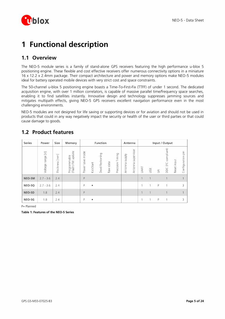
1.2 Product features
P= Planned
Table 1: Features of the NEO-5 Series
NEO-5 - Data Sheet
GPS.G5-MS5-07025-B3 Page 6 of 24
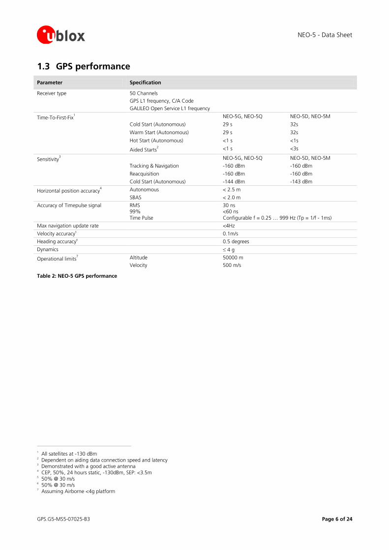
1.3 GPS performance
Parameter Specification
Receiver type 50 Channels
GPS L1 frequency, C/A Code
GALILEO Open Service L1 frequency
Time-To-First-Fix1 NEO-5G, NEO-5Q NEO-5D, NEO-5M
Cold Start (Autonomous) 29 s 32s
Warm Start (Autonomous) 29 s 32s
Hot Start (Autonomous) <1 s <1s
Aided Starts2 <1 s <3s
Sensitivity3 NEO-5G, NEO-5Q NEO-5D, NEO-5M
Tracking & Navigation -160 dBm -160 dBm
Reacquisition -160 dBm -160 dBm
Cold Start (Autonomous) -144 dBm -143 dBm
Horizontal position accuracy4 Autonomous < 2.5 m
SBAS < 2.0 m
Accuracy of Timepulse signal RMS 99%
Time Pulse
30 ns <60 ns
Configurable f = 0.25 … 999 Hz (Tp = 1/f - 1ms)
Max navigation update rate <4Hz
Velocity accuracy5 0.1m/s
Heading accuracy6 0.5 degrees
Dynamics 4 g
Operational limits7 Altitude
Velocity
50000 m
500 m/s
Table 2: NEO-5 GPS performance
1 All satellites at -130 dBm
2 Dependent on aiding data connection speed and latency
3 Demonstrated with a good active antenna
4 CEP, 50%, 24 hours static, -130dBm, SEP: <3.5m
5 50% @ 30 m/s
6 50% @ 30 m/s
7 Assuming Airborne <4g platform
NEO-5 - Data Sheet
GPS.G5-MS5-07025-B3 Page 7 of 24
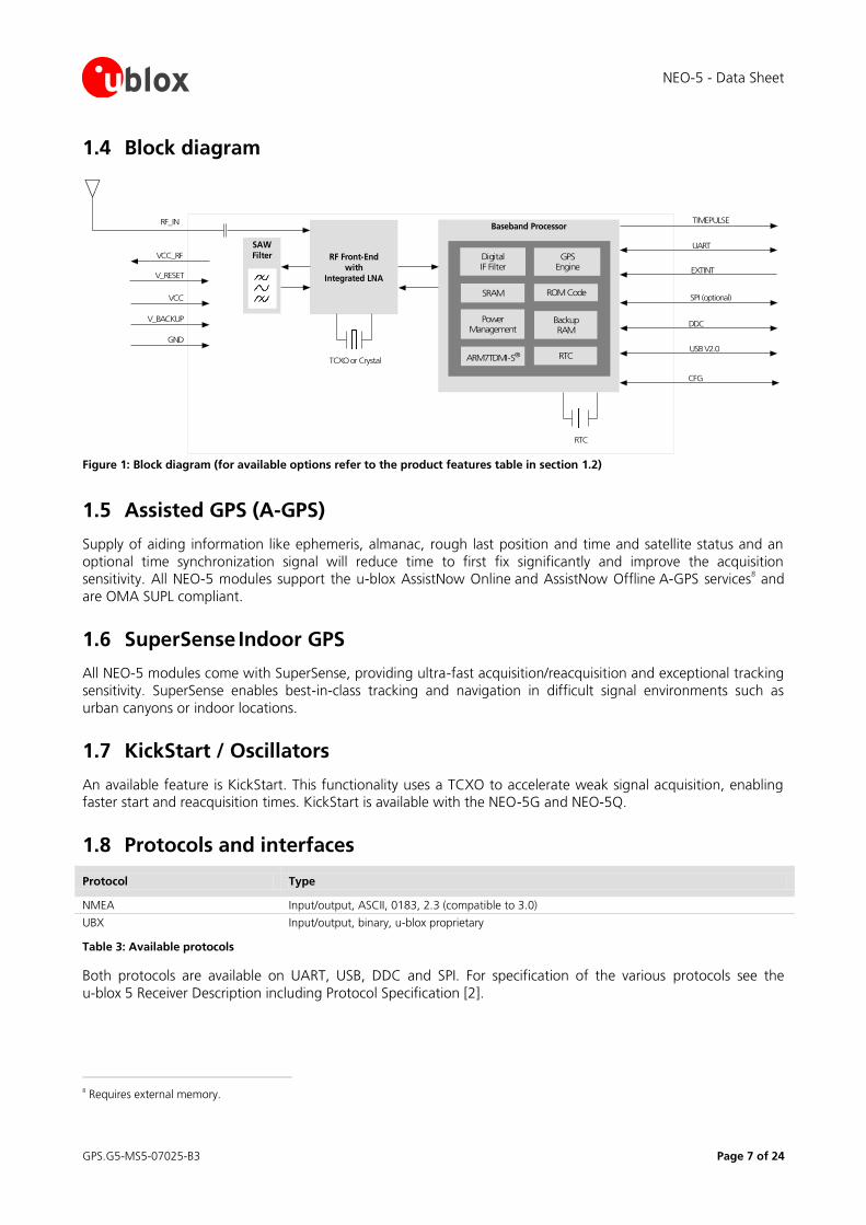
1.4 Block diagram
RF Front-End
withIntegrated LNA
Baseband Processor
PowerManagement
TCXO or Crystal
RTC
RF_IN
DigitalIF Filter
BackupRAM
ROM Code
GPSEngine
ARM7TDMI-S®
SRAM
SAW
Filter
RTC
VCC_RF
VCC
V_BACKUP
GND
SPI (optional)
DDC
TIMEPULSE
EXTINT
UART
USB V2.0
CFG
V_RESET
Figure 1: Block diagram (for available options refer to the product features table in section 1.2)
1.5 Assisted GPS (A-GPS)
Supply of aiding information like ephemeris, almanac, rough last position and time and satellite status and an
optional time synchronization signal will reduce time to first fix significantly and improve the acquisition sensitivity. All NEO-5 modules support the u-blox AssistNow Online
and AssistNow Offline
A-GPS services
8 and
are OMA SUPL compliant.
1.6 SuperSense Indoor GPS
All NEO-5 modules come with SuperSense, providing ultra-fast acquisition/reacquisition and exceptional tracking
sensitivity. SuperSense enables best-in-class tracking and navigation in difficult signal environments such as
urban canyons or indoor locations.
1.7 KickStart / Oscillators
An available feature is KickStart. This functionality uses a TCXO to accelerate weak signal acquisition, enabling faster start and reacquisition times. KickStart is available with the NEO-5G and NEO-5Q.
1.8 Protocols and interfaces
Protocol Type
NMEA Input/output, ASCII, 0183, 2.3 (compatible to 3.0)
UBX Input/output, binary, u-blox proprietary
Table 3: Available protocols
Both protocols are available on UART, USB, DDC and SPI. For specification of the various protocols see the
u-blox_5 Receiver Description including Protocol Specification [2].
8 Requires external memory.
NEO-5 - Data Sheet
GPS.G5-MS5-07025-B3 Page 8 of 24
NEO-5 modules support a number of peripheral interfaces for serial communication. The embedded firmware uses these interfaces according to their respective protocol specifications. For specific applications, the firmware
also supports the connection of peripheral devices, such as external memories, to some of the interfaces.
1.8.1 UART
NEO-5 modules include one configurable UART interface for serial communication (for information about
configuration see section 1.11).
1.8.2 USB
NEO-5 modules provide a USB version 2.0 FS (Full Speed, 12Mbit/s) interface as an alternative to the UART. The
pull-up resistor on USB_DP is integrated to signal a full-speed device to the host. The VDD_USB pin supplies the USB interface, independently from the VDD_IO pin.
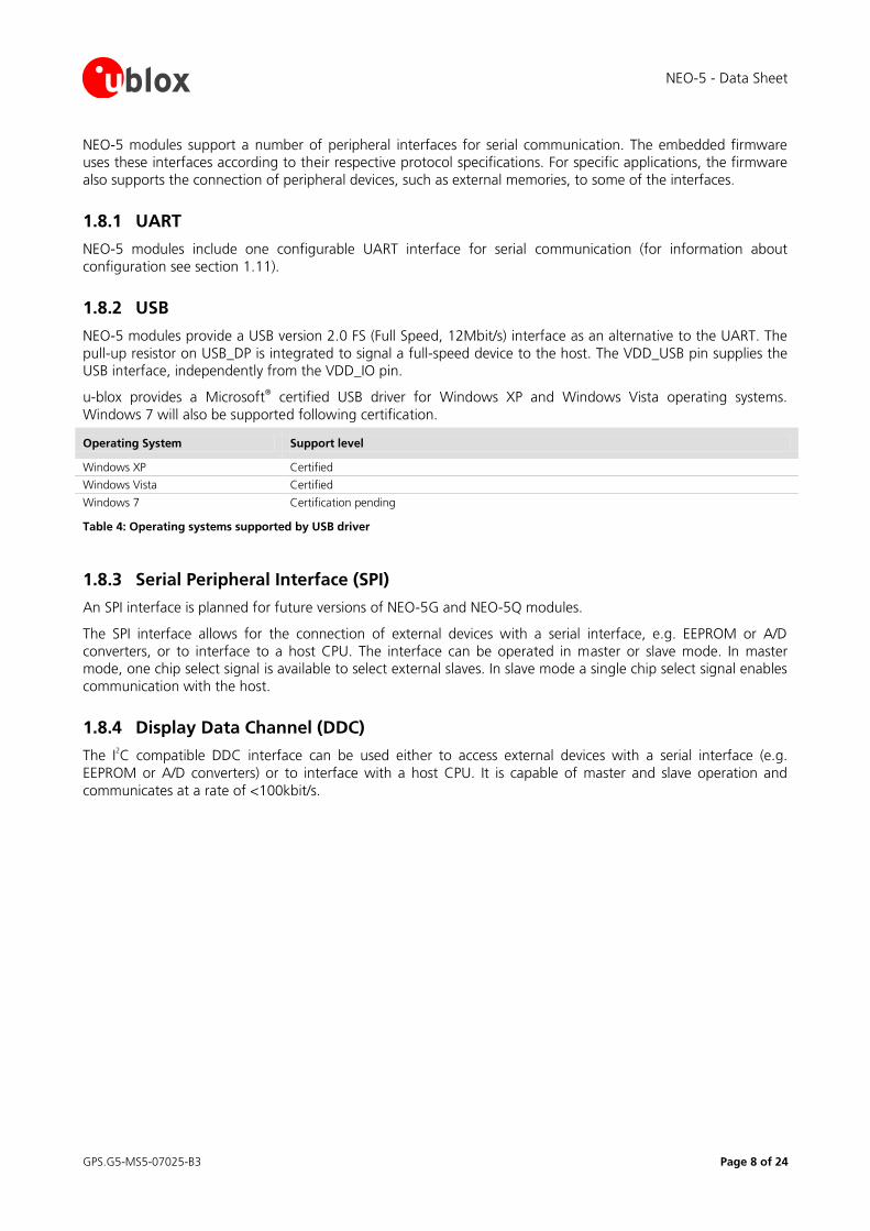
u-blox provides a Microsoft® certified USB driver for Windows XP and Windows Vista operating systems.
Windows 7 will also be supported following certification.
Operating System Support level
Windows XP Certified
Windows Vista Certified
Windows 7 Certification pending
Table 4: Operating systems supported by USB driver
1.8.3 Serial Peripheral Interface (SPI)
An SPI interface is planned for future versions of NEO-5G and NEO-5Q modules.
The SPI interface allows for the connection of external devices with a serial interface, e.g. EEPROM or A/D
converters, or to interface to a host CPU. The interface can be operated in master or slave mode. In master mode, one chip select signal is available to select external slaves. In slave mode a single chip select signal enables
communication with the host.
1.8.4 Display Data Channel (DDC)
The I2C compatible DDC interface can be used either to access external devices with a serial interface (e.g.
EEPROM or A/D converters) or to interface with a host CPU. It is capable of master and slave operation and
communicates at a rate of <100kbit/s.
NEO-5 - Data Sheet
GPS.G5-MS5-07025-B3 Page 9 of 24
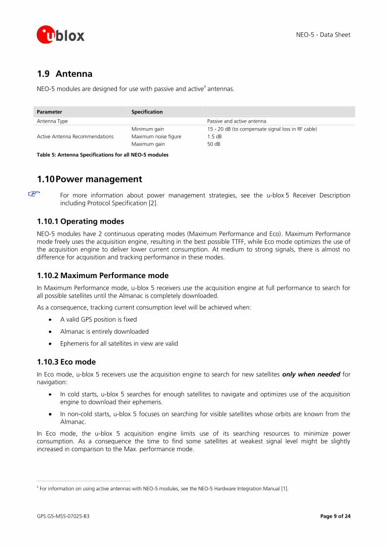
1.9 Antenna
NEO-5 modules are designed for use with passive and active9 antennas.
Parameter Specification
Antenna Type Passive and active antenna
Active Antenna Recommendations
Minimum gain
Maximum noise figure
Maximum gain
15 - 20 dB (to compensate signal loss in RF cable)
1.5 dB
50 dB
Table 5: Antenna Specifications for all NEO-5 modules
1.10 Power management
For more information about power management strategies, see the u-blox_5 Receiver Description
including Protocol Specification [2].
1.10.1 Operating modes
NEO-5 modules have 2 continuous operating modes (Maximum Performance and Eco). Maximum Performance
mode freely uses the acquisition engine, resulting in the best possible TTFF, while Eco mode optimizes the use of the acquisition engine to deliver lower current consumption. At medium to strong signals, there is almost no
difference for acquisition and tracking performance in these modes.
1.10.2 Maximum Performance mode
In Maximum Performance mode, u-blox 5 receivers use the acquisition engine at full performance to search for
all possible satellites until the Almanac is completely downloaded.
As a consequence, tracking current consumption level will be achieved when:
A valid GPS position is fixed
Almanac is entirely downloaded
Ephemeris for all satellites in view are valid
1.10.3 Eco mode
In Eco mode, u-blox 5 receivers use the acquisition engine to search for new satellites only when needed for navigation:
In cold starts, u-blox 5 searches for enough satellites to navigate and optimizes use of the acquisition
engine to download their ephemeris.
In non-cold starts, u-blox 5 focuses on searching for visible satellites whose orbits are known from the
Almanac.
In Eco mode, the u-blox 5 acquisition engine limits use of its searching resources to minimize power consumption. As a consequence the time to find some satellites at weakest signal level might be slightly
increased in comparison to the Max. performance mode.
9 For information on using active antennas with NEO-5 modules, see the NEO-5 Hardware Integration Manual [1].
NEO-5 - Data Sheet
GPS.G5-MS5-07025-B3 Page 10 of 24
u-blox 5 deactivates the acquisition engine as soon as a position is fixed and a sufficient number (at least 4) of satellites are being tracked. The tracking engine continues to search and track new satellites without orbit
information.
1.11 Configuration
1.11.1 Boot-time configuration
NEO-5 modules provide configuration pins for boot-time configuration. These become effective immediately after start-up. Once the module has started, the configuration settings may be modified with UBX configuration
messages. The modified settings remain effective until power-down or reset. If these settings have been stored
in battery-backup RAM, then the modified configuration will be retained, as long as the backup battery supply is not interrupted.
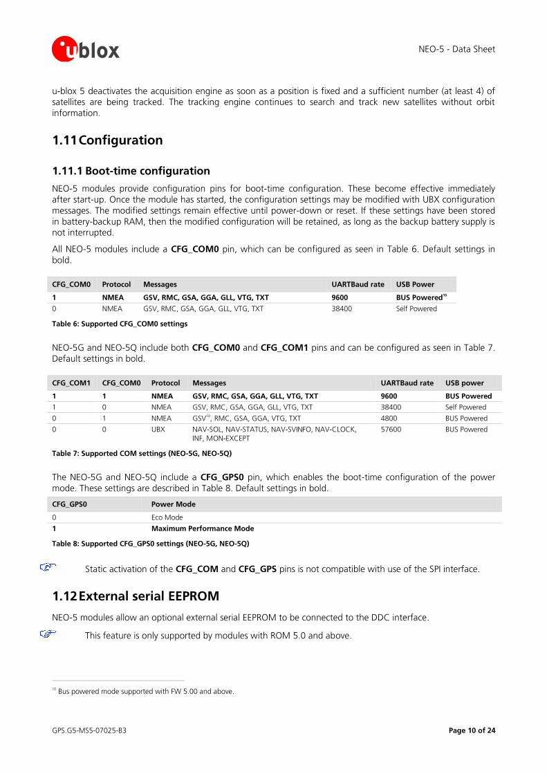
All NEO-5 modules include a CFG_COM0 pin, which can be configured as seen in Table 6. Default settings in
bold.
CFG_COM0 Protocol Messages UARTBaud rate USB Power
1 NMEA GSV, RMC, GSA, GGA, GLL, VTG, TXT 9600 BUS Powered10
0 NMEA GSV, RMC, GSA, GGA, GLL, VTG, TXT 38400 Self Powered
Table 6: Supported CFG_COM0 settings
NEO-5G and NEO-5Q include both CFG_COM0 and CFG_COM1 pins and can be configured as seen in Table 7. Default settings in bold.
CFG_COM1 CFG_COM0 Protocol Messages UARTBaud rate USB power
1 1 NMEA GSV, RMC, GSA, GGA, GLL, VTG, TXT 9600 BUS Powered
1 0 NMEA GSV, RMC, GSA, GGA, GLL, VTG, TXT 38400 Self Powered
0 1 NMEA GSV10, RMC, GSA, GGA, VTG, TXT 4800 BUS Powered
0 0 UBX NAV-SOL, NAV-STATUS, NAV-SVINFO, NAV-CLOCK,
INF, MON-EXCEPT
57600 BUS Powered
Table 7: Supported COM settings (NEO-5G, NEO-5Q)
The NEO-5G and NEO-5Q include a CFG_GPS0 pin, which enables the boot-time configuration of the power
mode. These settings are described in Table 8. Default settings in bold.
CFG_GPS0 Power Mode
0 Eco Mode
1 Maximum Performance Mode
Table 8: Supported CFG_GPS0 settings (NEO-5G, NEO-5Q)
Static activation of the CFG_COM and CFG_GPS pins is not compatible with use of the SPI interface.
1.12 External serial EEPROM
NEO-5 modules allow an optional external serial EEPROM to be connected to the DDC interface.
This feature is only supported by modules with ROM 5.0 and above.
10 Bus powered mode supported with FW 5.00 and above.
NEO-5 - Data Sheet
GPS.G5-MS5-07025-B3 Page 11 of 24
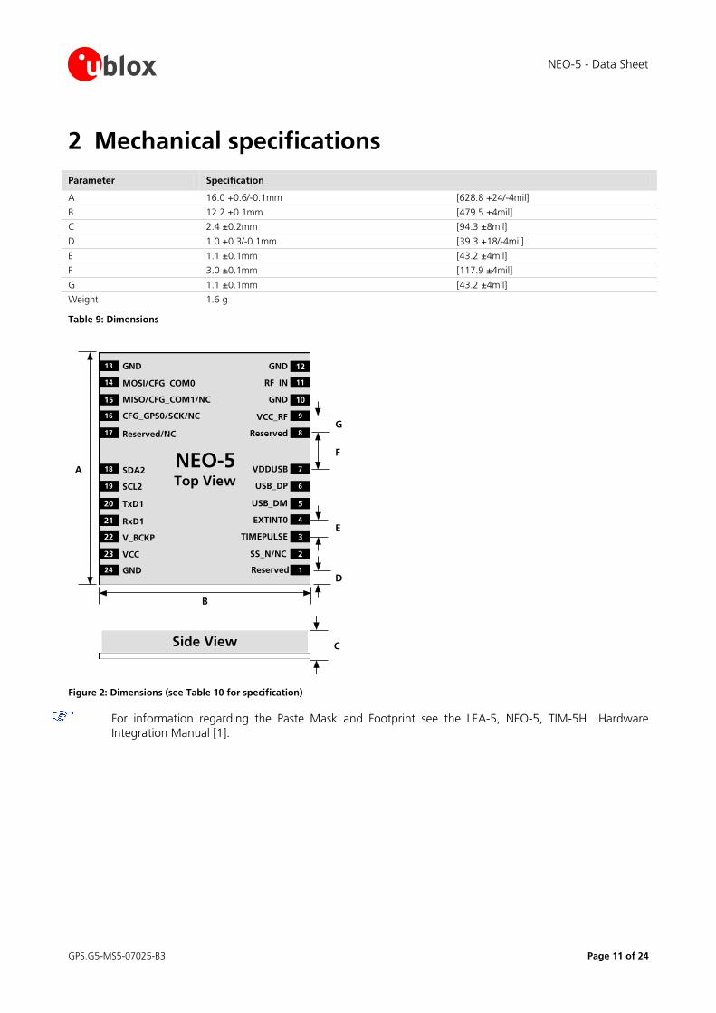
2 Mechanical specifications
Parameter Specification
A 16.0 +0.6/-0.1mm [628.8 +24/-4mil]
B 12.2 ±0.1mm [479.5 ±4mil]
C 2.4 ±0.2mm [94.3 ±8mil]
D 1.0 +0.3/-0.1mm [39.3 +18/-4mil]
E 1.1 ±0.1mm [43.2 ±4mil]
F 3.0 ±0.1mm [117.9 ±4mil]
G 1.1 ±0.1mm [43.2 ±4mil]
Weight 1.6 g
Table 9: Dimensions
Side View C
NEO-5Top View
B
1
2
3
4
5
6
7
8
9
10
11
12
24
22
21
20
19
18
17
16
15
14
13
23
GND Reserved
SS_N/NC
TIMEPULSE
EXTINT0
USB_DM
USB_DP
VDDUSB
Reserved
VCC_RF
GND
GND
RF_IN
GND
VCC
V_BCKP
RxD1
TxD1
SCL2
SDA2
Reserved/NC
CFG_GPS0/SCK/NC
MISO/CFG_COM1/NC
MOSI/CFG_COM0
E
F
A
D
G
Figure 2: Dimensions (see Table 10 for specification)
For information regarding the Paste Mask and Footprint see the LEA-5, NEO-5, TIM-5H Hardware
Integration Manual [1].
NEO-5 - Data Sheet
GPS.G5-MS5-07025-B3 Page 12 of 24
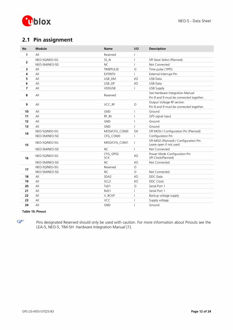
2.1 Pin assignment
No Module Name I/O Description
1 All Reserved I
2 NEO-5Q/NEO-5G SS_N I SPI Slave Select (Planned)
NEO-5M/NEO-5D NC I Not Connected
3 All TIMEPULSE O Time pulse (1PPS)
4 All EXTINT0 I External Interrupt Pin
5 All USB_DM I/O USB Data
6 All USB_DP I/O USB Data
7 All VDDUSB I USB Supply
8 All Reserved See Hardware Integration Manual
Pin 8 and 9 must be connected together.
9 All VCC_RF O Output Voltage RF section
Pin 8 and 9 must be connected together.
10 All GND I Ground
11 All RF_IN I GPS signal input
12 All GND I Ground
13 All GND I Ground
14 NEO-5Q/NEO-5G MOSI/CFG_COM0 O/I SPI MOSI / Configuration Pin (Planned)
NEO-5M/NEO-5D CFG_COM0 I Configuration Pin
15 NEO-5Q/NEO-5G MISO/CFG_COM1 I
SPI MISO (Planned) / Configuration Pin. Leave open if not used.
NEO-5M/NEO-5D NC I Not Connected
16 NEO-5Q/NEO-5G
CFG_GPS0 SCK
I/O Power Mode Configuration Pin SPI Clock(Planned)
NEO-5M/NEO-5D NC I/O Not Connected
17 NEO-5Q/NEO-5G Reserved O
NEO-5M/NEO-5D NC O Not Connected
18 All SDA2 I/O DDC Data
19 All SCL2 I/O DDC Clock
20 All TxD1 O Serial Port 1
21 All RxD1 I Serial Port 1
22 All V_BCKP I Backup voltage supply
23 All VCC I Supply voltage
24 All GND I Ground
Table 10: Pinout
Pins designated Reserved should only be used with caution. For more information about Pinouts see the
LEA-5, NEO-5, TIM-5H Hardware Integration Manual [1].
NEO-5 - Data Sheet
GPS.G5-MS5-07025-B3 Page 13 of 24
3 Electrical specifications
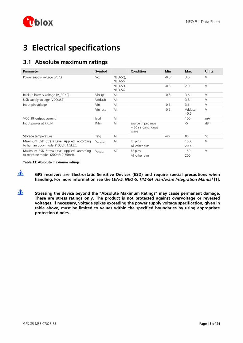
3.1 Absolute maximum ratings
Parameter Symbol Condition Min Max Units
Power supply voltage (VCC) Vcc NEO-5Q, NEO-5M
-0.5 3.6 V
NEO-5D, NEO-5G
-0.5 2.0 V
Backup battery voltage (V_BCKP) Vbckp All -0.5 3.6 V
USB supply voltage (VDDUSB) Vddusb All 3.8 V
Input pin voltage Vin All -0.5 3.6 V
Vin_usb All -0.5 Vddusb +0.5
V
VCC_RF output current Iccrf All 100 mA
Input power at RF_IN Prfin All source impedance
= 50 , continuous
wave
-5 dBm
Storage temperature Tstg All -40 85 °C
Maximum ESD Stress Level Applied; according
to human body model (100pF; 1.5k ).
VESD(HBM)
All RF pins
All other pins
1500
2000
V
Maximum ESD Stress Level Applied; according to machine model; (200pF; 0.75mH).
VESD(MM)
All RF pins
All other pins
150
200
V
Table 11: Absolute maximum ratings
GPS receivers are Electrostatic Sensitive Devices (ESD) and require special precautions when
handling. For more information see the LEA-5, NEO-5, TIM-5H Hardware Integration Manual [1].
Stressing the device beyond the “Absolute Maximum Ratings” may cause permanent damage. These are stress ratings only. The product is not protected against overvoltage or reversed
voltages. If necessary, voltage spikes exceeding the power supply voltage specification, given in
table above, must be limited to values within the specified boundaries by using appropriate protection diodes.
NEO-5 - Data Sheet
GPS.G5-MS5-07025-B3 Page 14 of 24
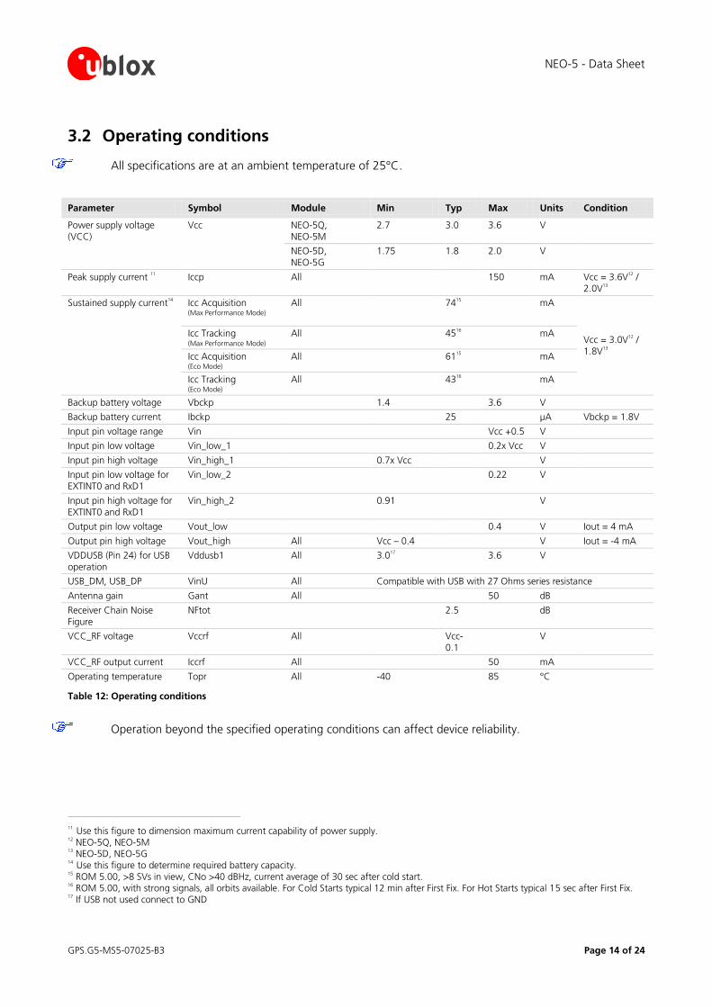
3.2 Operating conditions
All specifications are at an ambient temperature of 25°C.
Parameter Symbol Module Min Typ Max Units Condition
Power supply voltage (VCC)
Vcc NEO-5Q, NEO-5M
2.7 3.0 3.6 V
NEO-5D, NEO-5G
1.75 1.8 2.0 V
Peak supply current 11 Iccp All 150 mA Vcc = 3.6V
12 /
2.0V13
Sustained supply current14 Icc Acquisition
(Max Performance Mode) All 74
15 mA
Vcc = 3.0V12 /
1.8V13
Icc Tracking (Max Performance Mode)
All 4516 mA
Icc Acquisition (Eco Mode)
All 6115 mA
Icc Tracking (Eco Mode)
All 4316 mA
Backup battery voltage Vbckp 1.4 3.6 V
Backup battery current Ibckp 25 µA Vbckp = 1.8V
Input pin voltage range Vin Vcc +0.5 V
Input pin low voltage Vin_low_1 0.2x Vcc V
Input pin high voltage Vin_high_1 0.7x Vcc V
Input pin low voltage for EXTINT0 and RxD1
Vin_low_2 0.22 V
Input pin high voltage for EXTINT0 and RxD1
Vin_high_2 0.91 V
Output pin low voltage Vout_low 0.4 V Iout = 4 mA
Output pin high voltage Vout_high All Vcc – 0.4 V Iout = -4 mA
VDDUSB (Pin 24) for USB operation
Vddusb1 All 3.017 3.6 V
USB_DM, USB_DP VinU All Compatible with USB with 27 Ohms series resistance
Antenna gain Gant All 50 dB
Receiver Chain Noise Figure
NFtot 2.5 dB
VCC_RF voltage Vccrf All Vcc-0.1
V
VCC_RF output current Iccrf All 50 mA
Operating temperature Topr All -40 85 °C
Table 12: Operating conditions
Operation beyond the specified operating conditions can affect device reliability.
11 Use this figure to dimension maximum current capability of power supply.
12 NEO-5Q, NEO-5M
13 NEO-5D, NEO-5G
14 Use this figure to determine required battery capacity.
15 ROM 5.00, >8 SVs in view, CNo >40 dBHz, current average of 30 sec after cold start.
16 ROM 5.00, with strong signals, all orbits available. For Cold Starts typical 12 min after First Fix. For Hot Starts typical 15 sec after First Fix.
17 If USB not used connect to GND
NEO-5 - Data Sheet
GPS.G5-MS5-07025-B3 Page 15 of 24
4 Design-in
In order to obtain the necessary information to conduct a proper design-in, u-blox strongly recommends
consulting the LEA-5, NEO-5, TIM-5H Hardware Integration Manual [1].
5 Reliability tests and approvals
5.1 Reliability tests
Tests for product family qualifications according to ISO 16750.
5.2 Approvals
Products marked with this lead-free symbol on the product label comply with the
"Directive 2002/95/EC of the European Parliament and the Council on the Restriction of Use of certain Hazardous Substances in Electrical and Electronic Equipment" (RoHS).
All u-blox 5 GPS modules are RoHS compliant.
NEO-5 - Data Sheet
GPS.G5-MS5-07025-B3 Page 16 of 24
6 Product handling
6.1 Packaging
NEO-5 modules are delivered as hermetically sealed, reeled tapes in order to enable efficient production,
production lot set-up and tear-down.
Figure 3: Reeled u-blox 5 modules
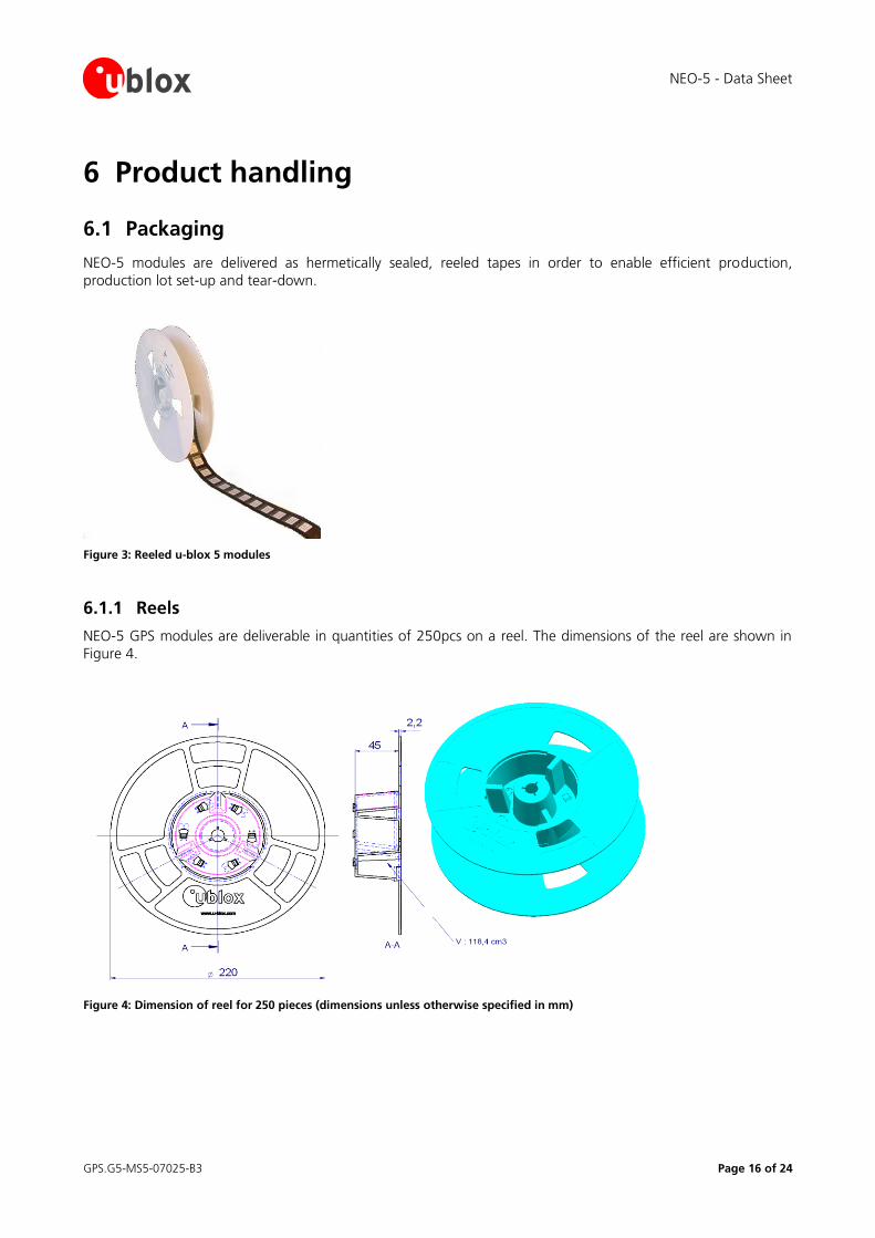
6.1.1 Reels
NEO-5 GPS modules are deliverable in quantities of 250pcs on a reel. The dimensions of the reel are shown in
Figure 4.
Figure 4: Dimension of reel for 250 pieces (dimensions unless otherwise specified in mm)
NEO-5 - Data Sheet
GPS.G5-MS5-07025-B3 Page 17 of 24
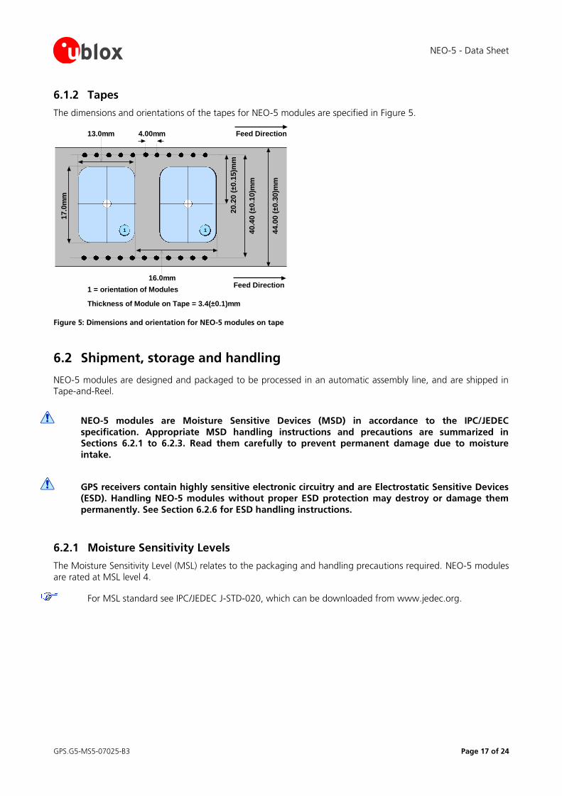
6.1.2 Tapes
The dimensions and orientations of the tapes for NEO-5 modules are specified in Figure 5.
1 1
17.0
mm
13.0mm
16.0mm
20.2
0 (
±0.1
5)m
m
40.4
0 (
±0.1
0)m
m
44.0
0 (
±0.3
0)m
m
4.00mm
1 = orientation of Modules
Thickness of Module on Tape = 3.4(±0.1)mm
Feed Direction
Feed Direction
Figure 5: Dimensions and orientation for NEO-5 modules on tape
6.2 Shipment, storage and handling
NEO-5 modules are designed and packaged to be processed in an automatic assembly line, and are shipped in Tape-and-Reel.
NEO-5 modules are Moisture Sensitive Devices (MSD) in accordance to the IPC/JEDEC
specification. Appropriate MSD handling instructions and precautions are summarized in Sections 6.2.1 to 6.2.3. Read them carefully to prevent permanent damage due to moisture
intake.
GPS receivers contain highly sensitive electronic circuitry and are Electrostatic Sensitive Devices (ESD). Handling NEO-5 modules without proper ESD protection may destroy or damage them
permanently. See Section 6.2.6 for ESD handling instructions.
6.2.1 Moisture Sensitivity Levels
The Moisture Sensitivity Level (MSL) relates to the packaging and handling precautions required. NEO-5 modules
are rated at MSL level 4.
For MSL standard see IPC/JEDEC J-STD-020, which can be downloaded from www.jedec.org.
NEO-5 - Data Sheet
GPS.G5-MS5-07025-B3 Page 18 of 24
6.2.2 Shipment
Table 13 summarizes the dry pack requirements for different MSL levels in the IPC/JDEC specification.
MSL Level Dry Pack Requirement
1 Optional
2 Required
2a Required
3 Required
4 Required
Table 13: JEDEC specification of dry pack requirements
According to IPC/JEDEC specification J-STD-020, if a device passes MSL level 1, it is classified as not moisture
sensitive and does not require dry pack. If a device fails level 1 but passes a higher numerical level, it is classified as moisture sensitive and must be dry packed in accordance with J-STD-033.
NEO-5 modules are delivered on Tape-and-Reels in a hermetically sealed package ("dry bag") to prevent
moisture intake and protect against electrostatic discharge. For protection from physical damage, the reels are individually packed in cartons.
Carrier materials such as trays, tubes, reels, etc., that are placed in the Moisture Barrier Bag (MBB) can affect the moisture level within the MBB. Therefore, the effect of these materials is compensated by adding additional
desiccant in the MBB to ensure the shelf life of the SMD packages.
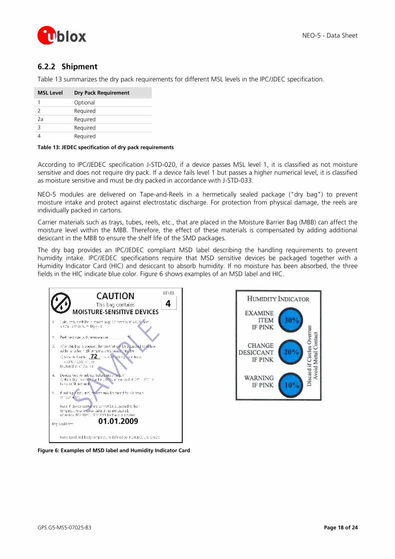
The dry bag provides an IPC/JEDEC compliant MSD label describing the handling requirements to prevent humidity intake. IPC/JEDEC specifications require that MSD sensitive devices be packaged together with a
Humidity Indicator Card (HIC) and desiccant to absorb humidity. If no moisture has been absorbed, the three
fields in the HIC indicate blue color. Figure 6 shows examples of an MSD label and HIC.
Figure 6: Examples of MSD label and Humidity Indicator Card
4
72
01.01.2009
NEO-5 - Data Sheet
GPS.G5-MS5-07025-B3 Page 19 of 24
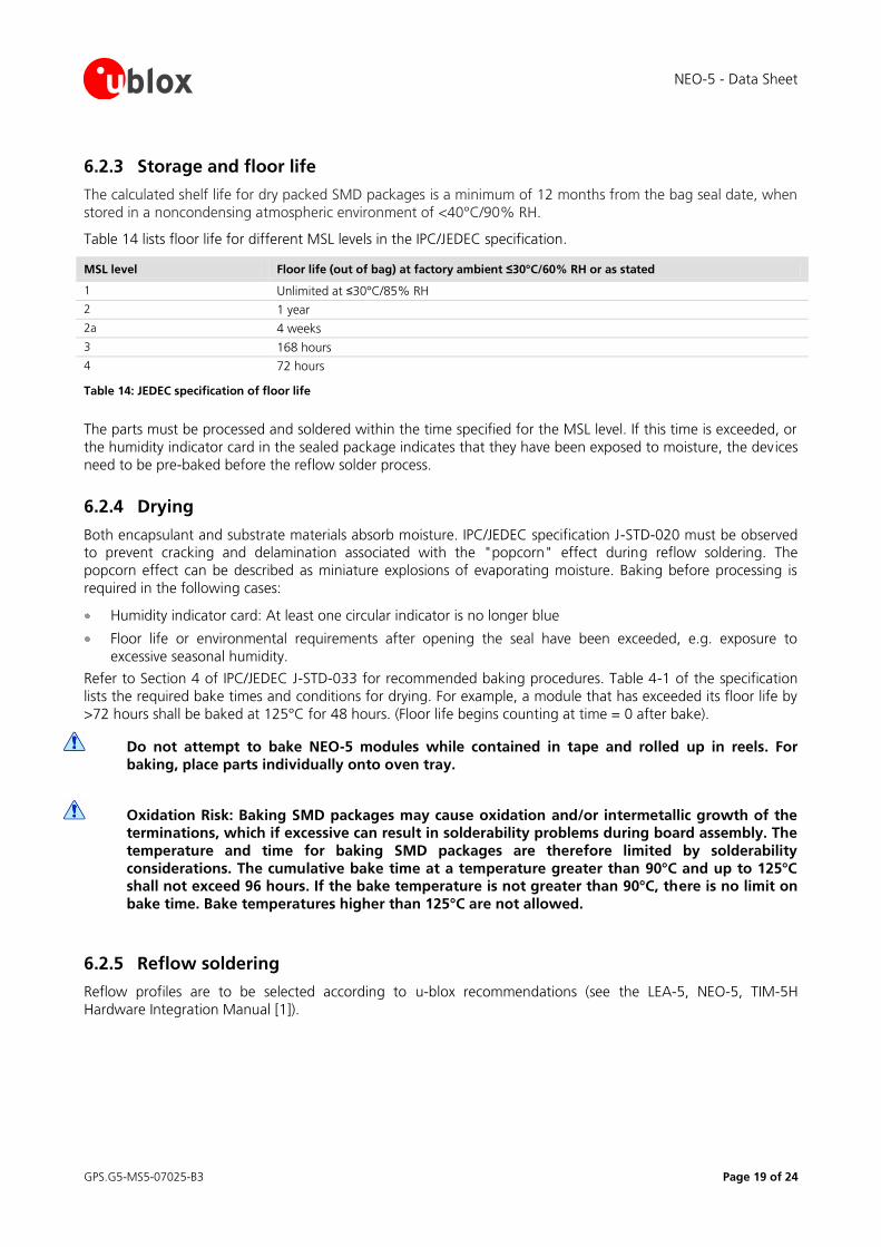
6.2.3 Storage and floor life
The calculated shelf life for dry packed SMD packages is a minimum of 12 months from the bag seal date, when
stored in a noncondensing atmospheric environment of <40°C/90% RH.
Table 14 lists floor life for different MSL levels in the IPC/JEDEC specification.
MSL level Floor life (out of bag) at factory ambient ≤30°C/60% RH or as stated
1 Unlimited at ≤30°C/85% RH
2 1 year
2a 4 weeks
3 168 hours
4 72 hours
Table 14: JEDEC specification of floor life
The parts must be processed and soldered within the time specified for the MSL level. If this time is exceeded, or
the humidity indicator card in the sealed package indicates that they have been exposed to moisture, the devices
need to be pre-baked before the reflow solder process.
6.2.4 Drying
Both encapsulant and substrate materials absorb moisture. IPC/JEDEC specification J-STD-020 must be observed to prevent cracking and delamination associated with the "popcorn" effect during reflow soldering. The
popcorn effect can be described as miniature explosions of evaporating moisture. Baking before processing is
required in the following cases:
Humidity indicator card: At least one circular indicator is no longer blue
Floor life or environmental requirements after opening the seal have been exceeded, e.g. exposure to
excessive seasonal humidity.
Refer to Section 4 of IPC/JEDEC J-STD-033 for recommended baking procedures. Table 4-1 of the specification
lists the required bake times and conditions for drying. For example, a module that has exceeded its floor life by
>72 hours shall be baked at 125°C for 48 hours. (Floor life begins counting at time = 0 after bake).
Do not attempt to bake NEO-5 modules while contained in tape and rolled up in reels. For
baking, place parts individually onto oven tray.
Oxidation Risk: Baking SMD packages may cause oxidation and/or intermetallic growth of the terminations, which if excessive can result in solderability problems during board assembly. The
temperature and time for baking SMD packages are therefore limited by solderability
considerations. The cumulative bake time at a temperature greater than 90°C and up to 125°C shall not exceed 96 hours. If the bake temperature is not greater than 90°C, there is no limit on
bake time. Bake temperatures higher than 125°C are not allowed.
6.2.5 Reflow soldering
Reflow profiles are to be selected according to u-blox recommendations (see the LEA-5, NEO-5, TIM-5H
Hardware Integration Manual [1]).
NEO-5 - Data Sheet
GPS.G5-MS5-07025-B3 Page 20 of 24
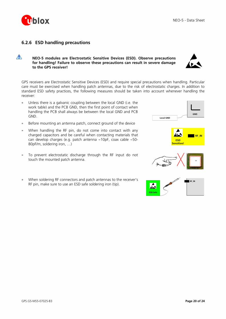
6.2.6 ESD handling precautions
NEO-5 modules are Electrostatic Sensitive Devices (ESD). Observe precautions for handling! Failure to observe these precautions can result in severe damage
to the GPS receiver!
GPS receivers are Electrostatic Sensitive Devices (ESD) and require special precautions when handling. Particular care must be exercised when handling patch antennas, due to the risk of electrostatic charges. In addition to
standard ESD safety practices, the following measures should be taken into account whenever handling the
receiver:
Unless there is a galvanic coupling between the local GND (i.e. the
work table) and the PCB GND, then the first point of contact when
handling the PCB shall always be between the local GND and PCB GND.
Before mounting an antenna patch, connect ground of the device
GND
Local GND
When handling the RF pin, do not come into contact with any
charged capacitors and be careful when contacting materials that
can develop charges (e.g. patch antenna ~10pF, coax cable ~50-80pF/m, soldering iron, …)
ESDSensitive!
RF_IN
To prevent electrostatic discharge through the RF input do not
touch the mounted patch antenna.
When soldering RF connectors and patch antennas to the receiver’s
RF pin, make sure to use an ESD safe soldering iron (tip). RF_IN
ESD Safe
NEO-5 - Data Sheet
GPS.G5-MS5-07025-B3 Page 21 of 24
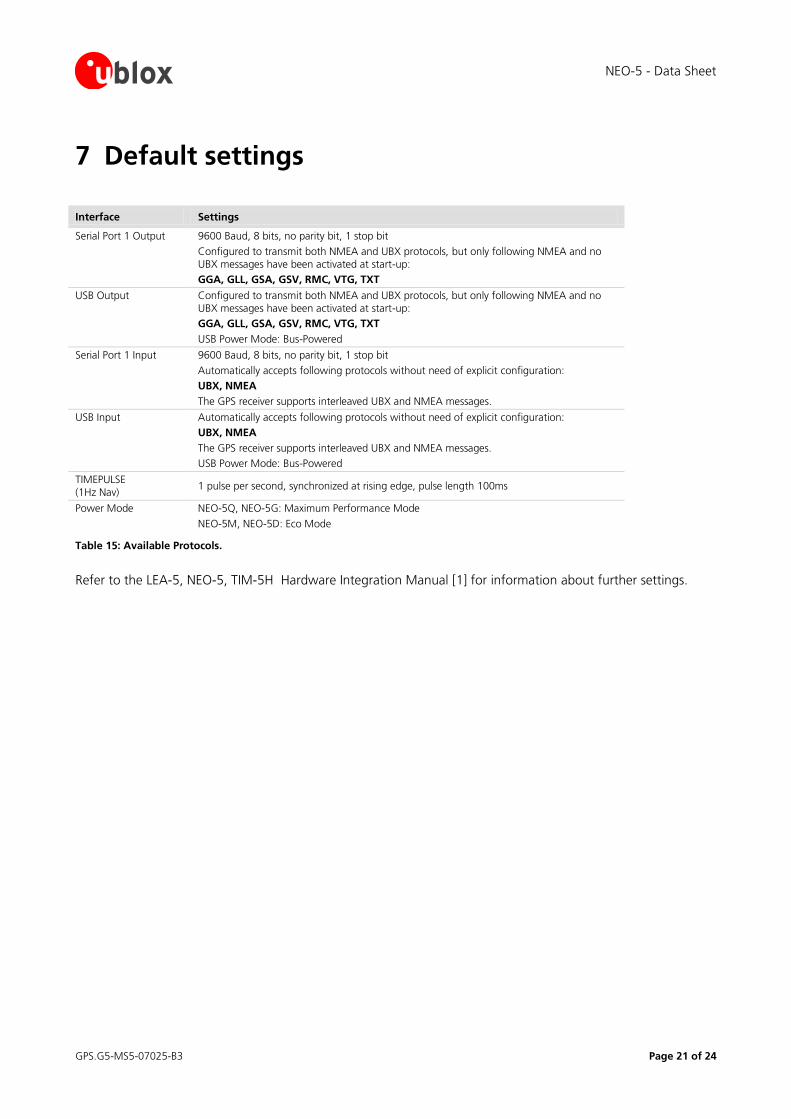
7 Default settings
Interface Settings
Serial Port 1 Output
9600 Baud, 8 bits, no parity bit, 1 stop bit
Configured to transmit both NMEA and UBX protocols, but only following NMEA and no UBX messages have been activated at start-up:
GGA, GLL, GSA, GSV, RMC, VTG, TXT
USB Output Configured to transmit both NMEA and UBX protocols, but only following NMEA and no UBX messages have been activated at start-up:
GGA, GLL, GSA, GSV, RMC, VTG, TXT
USB Power Mode: Bus-Powered
Serial Port 1 Input 9600 Baud, 8 bits, no parity bit, 1 stop bit
Automatically accepts following protocols without need of explicit configuration:
UBX, NMEA
The GPS receiver supports interleaved UBX and NMEA messages.
USB Input Automatically accepts following protocols without need of explicit configuration:
UBX, NMEA
The GPS receiver supports interleaved UBX and NMEA messages.
USB Power Mode: Bus-Powered
TIMEPULSE (1Hz Nav)
1 pulse per second, synchronized at rising edge, pulse length 100ms
Power Mode NEO-5Q, NEO-5G: Maximum Performance Mode
NEO-5M, NEO-5D: Eco Mode
Table 15: Available Protocols.
Refer to the LEA-5, NEO-5, TIM-5H Hardware Integration Manual [1] for information about further settings.
NEO-5 - Data Sheet
GPS.G5-MS5-07025-B3 Page 22 of 24
8 Labeling and ordering information
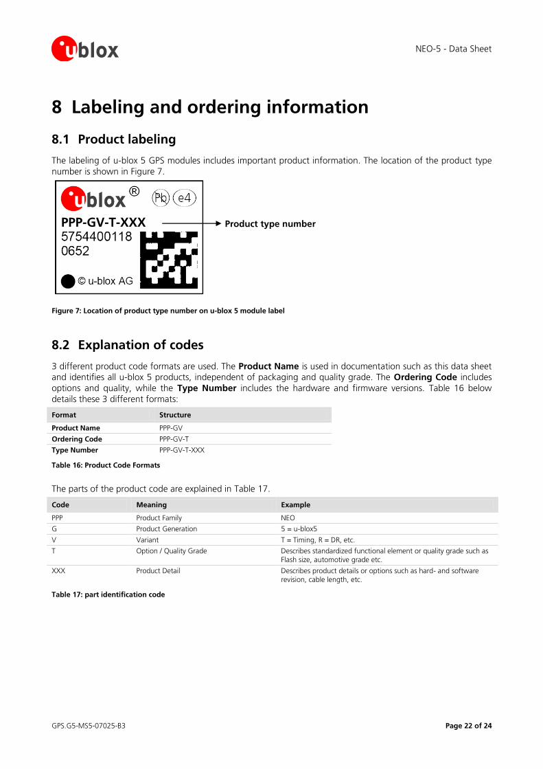
8.1 Product labeling
The labeling of u-blox 5 GPS modules includes important product information. The location of the product type
number is shown in Figure 7.
Product type number
Figure 7: Location of product type number on u-blox 5 module label
8.2 Explanation of codes
3 different product code formats are used. The Product Name is used in documentation such as this data sheet and identifies all u-blox 5 products, independent of packaging and quality grade. The Ordering Code includes
options and quality, while the Type Number includes the hardware and firmware versions. Table 16 below
details these 3 different formats:
Format Structure
Product Name PPP-GV
Ordering Code PPP-GV-T
Type Number PPP-GV-T-XXX
Table 16: Product Code Formats
The parts of the product code are explained in Table 17.
Code Meaning Example
PPP Product Family NEO
G Product Generation 5 = u-blox5
V Variant T = Timing, R = DR, etc.
T Option / Quality Grade Describes standardized functional element or quality grade such as Flash size, automotive grade etc.
XXX Product Detail Describes product details or options such as hard- and software revision, cable length, etc.
Table 17: part identification code
PPP-GV-T-XXX
NEO-5 - Data Sheet
GPS.G5-MS5-07025-B3 Page 23 of 24
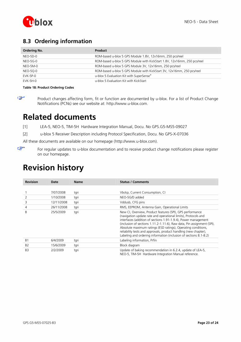
8.3 Ordering information
Ordering No. Product
NEO-5D-0 ROM-based u-blox 5 GPS Module 1.8V, 12x16mm, 250 pcs/reel
NEO-5G-0 ROM-based u-blox 5 GPS Module with KickStart 1.8V, 12x16mm, 250 pcs/reel
NEO-5M-0 ROM-based u-blox 5 GPS Module 3V, 12x16mm, 250 pcs/reel
NEO-5Q-0 ROM-based u-blox 5 GPS Module with KickStart 3V, 12x16mm, 250 pcs/reel
EVK-5P-0 u-blox 5 Evaluation Kit with SuperSense®
EVK-5H-0 u-blox 5 Evaluation Kit with KickStart
Table 18: Product Ordering Codes
Product changes affecting form, fit or function are documented by u-blox. For a list of Product Change Notifications (PCNs) see our website at: http://www.u-blox.com.
Related documents [1] LEA-5, NEO-5, TIM-5H Hardware Integration Manual, Docu. No GPS.G5-MS5-09027
[2] u-blox 5 Receiver Description including Protocol Specification, Docu. No GPS-X-07036
All these documents are available on our homepage (http://www.u-blox.com).
For regular updates to u-blox documentation and to receive product change notifications please register
on our homepage.
Revision history
Revision Date Name Status / Comments
1 7/07/2008 tgri Vbckp, Current Consumption, CI
2 1/10/2008 tgri NEO-5G/D added
3 12/11/2008 tgri Vddusb, CFG pins
4 26/11/2008 tgri RMS, EEPROM, Antenna Gain, Operational Limits
B 25/5/2009 tgri New CI, Overview, Product features (SPI), GPS performance (navigation update rate and operational limits), Protocols and interfaces (addition of sections 1.91-1.9.4), Power management (inclusion of sections 1.11.2-1.11.6), Raw data, Pin assignment (SPI), Absolute maximum ratings (ESD ratings), Operating conditions, reliability tests and approvals, product handling (new chapter),
Labeling and ordering information (inclusion of sections 8.1-8.2)
B1 6/4/2009 tgri Labeling information, Prfin
B2 15/6/2009 tgri Block diagram
B3 2/2/2009 tgri Update of baking recommendation in 6.2.4, update of LEA-5, NEO-5, TIM-5H Hardware Integration Manual reference.
NEO-5 - Data Sheet
GPS.G5-MS5-07025-B3 Page 24 of 24
Contact For complete contact information visit us at www.u-blox.com
Offices
North, Central and South America
u-blox America, Inc.
Phone: +1 (703) 483 3180
E-mail: [email protected]
Regional Office West Coast:
Phone: +1 (703) 483 3184
E-mail: [email protected]
Technical Support:
Phone: +1 (703) 483 3185
E-mail: [email protected]
Headquarters Europe, Middle East, Africa
u-blox AG
Phone: +41 44 722 74 44
E-mail: [email protected]
Technical Support:
Phone: +41 44 722 74 44 E-mail: [email protected]
Asia, Australia, Pacific
u-blox Singapore Pte. Ltd.
Phone: +65 6734 3811
E-mail: [email protected]
Support: [email protected]
Regional Office China:
Phone: +86 10 68 133 545 E-mail: [email protected]
Support: [email protected]
Regional Office Japan:
Phone: +81 03 5775 3850
E-mail: [email protected] Support: [email protected]
Regional Office Korea:
Phone: +82 2 542 0861 E-mail: [email protected]
Support: [email protected]
Regional Office Taiwan:
Phone: +886 2 2657 1090
E-mail: [email protected] Support: [email protected]