Embed Size (px)
Citation preview

C94-M8P u-blox RTK Application Board Package User Guide
Abstract
This document describes the structure and use of the C94-M8P RTK application board package and provides information for evaluating
and testing u-blox NEO-M8P high precision positioning modules.
www.u-blox.com
UBX-15031066 - R07

UBX-15031066 - R07 Early Production Information Page 2 of 47
Document Information
Title C94-M8P
Subtitle u-blox RTK Application Board Package
Document type User Guide
Document number UBX-15031066
Revision and date R07 07-Jul-2017
Document status Early Production Information
Document status explanation
Objective Specification Document contains target values. Revised and supplementary data will be published later.
Advance Information Document contains data based on early testing. Revised and supplementary data will be published later.
Early Production Information Document contains data from product verification. Revised and supplementary data may be published later.
Production Information Document contains the final product specification.
This document applies to the following products:
Product name Type number Firmware/FLASH version PCN reference
C94-M8P C94-M8P-1-10 FLASH FW3.01 HPG1.40 UBX-17023320
C94-M8P C94-M8P-1-11 FLASH FW3.01 HPG1.40 N/A
C94-M8P C94-M8P-2-10 FLASH FW3.01 HPG1.40 UBX-17023320
C94-M8P C94-M8P-2-11 FLASH FW3.01 HPG1.40 N/A
C94-M8P C94-M8P-3-10 FLASH FW3.01 HPG1.40 UBX-17023320
C94-M8P C94-M8P-3-11 FLASH FW3.01 HPG1.40 N/A
C94-M8P C94-M8P-4-10 FLASH FW3.01 HPG1.40 UBX-17023320
C94-M8P C94-M8P-4-11 FLASH FW3.01 HPG1.40 N/A
u-blox reserves all rights to this document and the information contained herein. Products, names, logos and designs described herein may in whole or in part be subject to intellectual property rights. Reproduction, use, modification or disclosure to third parties of this document or any part thereof without the express permission of u-blox is strictly prohibited.
The information contained herein is provided “as is” and u-blox assumes no liability for the use of the information. No warranty, either express or implied, is given, including but not limited, with respect to the accuracy, correctness, reliability and fitness for a particular purpose of the information. This document may be revised by u-blox at any time. For most recent documents, please visit www.u-blox.com.
Copyright © 2017, u-blox AG

C94-M8P - User Guide
UBX-15031066 - R07 Early Production Information Preface
Page 3 of 47
Preface
Using this guide
This guide assumes, the user has basic computer skills and is familiar with the Windows Graphical User Interface
(GUI) and GNSS receiver environments.
The following symbols are used in the document to highlight information:
A warning symbol indicates actions that could negatively impact or damage the device.
An index finger points out key information pertaining to device operation and performance.
Warnings and certifications
CAUTION! IN THE UNLIKELY EVENT OF A FAILURE IN THE INTERNAL PROTECTION
CIRCUITRY THERE IS A RISK OF AN EXPLOSION WHEN CHARGING FULLY OR PARTIALLY DISCHARGED BATTERIES. REPLACE THE BATTERY IF IT NO LONGER
HAS SUFFICIENT CHARGE FOR UNIT OPERATION. CONTROL THE BATTERY BEFORE
USING IF THE DEVICE HAS NOT BEEN OPERATED FOR AN EXTENDED PERIOD OF TIME.
Products marked with this lead-free symbol on the product label comply with the “Directive 2002/95/EC and Directive 2011/65/EU of the European Parliament and the
Council on the Restriction of Use of certain Hazardous Substances in Electrical and
Electronic Equipment” (RoHS).
C94-M8P application board is RoHS compliant.

C94-M8P - User Guide
UBX-15031066 - R07 Early Production Information Contents
Page 4 of 47
Contents
Preface ................................................................................................................................ 3
Using this guide ............................................................................................................................................... 3
Warnings and certifications ............................................................................................................................. 3
Contents .............................................................................................................................. 4
1 Introduction .................................................................................................................. 7
1.1 Overview .............................................................................................................................................. 7
1.2 C94-M8P package ................................................................................................................................ 7
1.3 Software requirements ......................................................................................................................... 7
1.4 System requirements ............................................................................................................................ 7
2 Specification ................................................................................................................. 8
3 Getting started ............................................................................................................. 9
3.1 Software installation ............................................................................................................................. 9
3.2 NEO-M8P and radio modem firmware .................................................................................................. 9
3.3 Hardware installation .......................................................................................................................... 10
3.3.1 GNSS antenna considerations ...................................................................................................... 10
4 Configuration ............................................................................................................. 11
4.1 GNSS constellation configuration ........................................................................................................ 11
4.2 Static RTK configuration ..................................................................................................................... 11
4.2.1 Base station operation ................................................................................................................. 12
4.2.2 Specifying a fixed position ........................................................................................................... 12
4.2.3 Using the self survey-in facility ..................................................................................................... 12
4.2.4 Configuring RTCM messages ....................................................................................................... 14
4.2.5 NEO-M8P UART settings for the Base .......................................................................................... 16
4.2.6 Rover configuration ..................................................................................................................... 16
4.2.7 NEO-M8P UART settings for the Rover ........................................................................................ 17
4.2.8 Navigation rates supported with standard RTK ............................................................................ 17
4.3 Moving baseline RTK Configuration .................................................................................................... 17
4.3.1 Base station operation ................................................................................................................. 17
4.3.2 NEO-M8P UART settings for Base ................................................................................................ 21
4.3.3 Navigation rates supported with moving baseline operation ........................................................ 22
4.3.4 Rover with moving baseline ......................................................................................................... 23
4.3.5 Message Latency ......................................................................................................................... 23
5 Operation .................................................................................................................... 24
5.1 Standard RTK mode ............................................................................................................................ 24
5.1.1 Base station in operation ............................................................................................................. 24
5.1.2 Rover in operation ....................................................................................................................... 24

C94-M8P - User Guide
UBX-15031066 - R07 Early Production Information Contents
Page 5 of 47
5.2 Moving baseline mode ....................................................................................................................... 25
5.2.1 Base station in operation ............................................................................................................. 25
5.2.2 Rover in operation ....................................................................................................................... 26
5.3 Monitoring the quality of the RTCM stream ........................................................................................ 27
5.3.1 Moving baseline .......................................................................................................................... 28
6 Evaluation interfaces ................................................................................................. 29
6.1 RS232/UART Interface ........................................................................................................................ 29
6.2 USB interface ...................................................................................................................................... 29
6.3 J8 connector ....................................................................................................................................... 29
6.4 Battery connector ............................................................................................................................... 30
6.5 LED ..................................................................................................................................................... 30
6.6 Antenna connectors ........................................................................................................................... 30
6.6.1 Radio antenna connector ............................................................................................................ 30
6.6.2 GNSS antenna connector ............................................................................................................ 31
6.7 Wired serial RTCM3 connection between Base and Rover ................................................................... 31
7 Block diagram ............................................................................................................. 32
8 Board layout ............................................................................................................... 33
9 Schematic .................................................................................................................... 34
Appendix .......................................................................................................................... 35
A Glossary ...................................................................................................................... 35
B Radio communication link configuration ................................................................. 35
B.1 Serial console terminal installation ...................................................................................................... 38
C Updating C94 radio modem firmware ...................................................................... 39
C.1 Updating procedure............................................................................................................................ 40
Please download the correct firmware for your C94 variant from the u-blox GitHub website:
https://github.com/u-blox/C94-application-board-radio-firmware/ ................................................................. 40
There are two parts to the firmware, a Boot loader (BL) and the Firmware itself (FW). ................................... 40
D Notes on FW3.01 HPG1.40 ......................................................................................... 41
E Notes on hardware .................................................................................................... 41
E.1 For C94 radio firmware not in current production low latency firmware as indicated in Table 9: ......... 41
E.2 For C94 radio firmware that is current production low latency firmware as indicated in Table 9: ........ 42
E.3 C94 Variants -00 ................................................................................................................................ 42
E.3.1 Overview ..................................................................................................................................... 42
E.3.2 Connectors.................................................................................................................................. 42
E.3.3 Dimensions.................................................................................................................................. 43
F Hardware modification .............................................................................................. 44

C94-M8P - User Guide
UBX-15031066 - R07 Early Production Information Contents
Page 6 of 47
Related documents........................................................................................................... 46
Revision history ................................................................................................................ 46
Contact .............................................................................................................................. 47

C94-M8P - User Guide
UBX-15031066 - R07 Early Production Information Introduction
Page 7 of 47
1 Introduction
1.1 Overview
The C94-M8P application board package provides the means for efficient integration and evaluation of
NEO-M8P, u-blox’s M8 high precision GNSS modules.
The NEO-M8P module series introduces the concept of a “Rover” and a “Base Station”. By using a correction data stream from the Base Station, the Rover can output its relative position with stunning cm-level accuracy in
good environments.
The C94-M8P board integrates the NEO-M8P-2 module with both Base Station and Rover functionality. The C94-M8P includes a UHF radio link, allowing for easy setup and fast prototyping. The board also provides
connector pins, enabling a simple wired connection or communication alternatives using u-blox cellular and
short-range technologies.
The C94-M8P application board package comes in four variants, each with an individually configured radio link
to meet different radio frequency requirements in different regions:
C94-M8P-1-10/11 for China (433 MHz)
C94-M8P-2-10/11 for USA and Canada (915 MHz)
C94-M8P-3-10/11 or C94-M8P-3-10 for Europe (433 MHz)
C94-M8P-4-10/11 for Japan (920 MHz)
A label showing the application variant (ordering code) is located at the top-right corner of the board. For
information about variants with the old board version (C94-M8P-1-00, C94-M8P-2-00 and C94-M8P-3-00) refer
to Appendix E.3.
1.2 C94-M8P package
The C94-M8P package includes:
2 application boards (both with a NEO-M8P-2 module)
2 external UHF antennas
2 external active GNSS antennas
2 antenna ground planes
2 USB cables
A RF-shield is attached on the top of the radio modem.
A plastic enclosure is attached on the top of the GNSS module. The purpose of the enclosure is to prevent
airflow affecting TCXO performance.
1.3 Software requirements
To comply with the instructions and examples in this document, the following software is required:
The latest version of u-center for Windows (currently version 8.26). You can download it from https://www.u-blox.com/en/product/c94-m8p
Serial console terminal, for example Putty
1.4 System requirements
The following system requirements are required to follow the instructions and examples in this document:
PC with USB interface
Operating system: Windows Vista onwards (x86 and x64 versions)
GNSS USB drivers are automatically installed when installing u-center.

C94-M8P - User Guide
UBX-15031066 - R07 Early Production Information Specification
Page 8 of 47
2 Specification
Parameter Specification
Interfaces 1 USB port for GNSS data and power supply
1 RS232, for radio link configuration
Connection pins for UART communication (e.g. C027), 3.3 V
SMA connector External GNSS antenna and UHF antenna
Dimensions 75 mm x 55 mm
Weight 35 g
Power Supply 5 V via USB or externally powered by battery (5.05 mm pitch 2-pin, 3.7 V – 20 V) powered
1 battery connector
Normal Operating temperature -40 °C to +65 °C
Table 1: C94-M8P application board specification

C94-M8P - User Guide
UBX-15031066 - R07 Early Production Information Getting started
Page 9 of 47
3 Getting started
3.1 Software installation
The latest version of u-center is needed for the examples and procedures described in this document. Internet
access is also required during the software installation to ensure that the most up-to-date components are
installed on your system. After installation, the u-center application can be found in the”u-blox” folder in the Start->Program menu.
3.2 NEO-M8P and radio modem firmware
Before starting evaluation, check that the application boards are using the latest firmware for both the NEO-M8P and radio modem modules.
If you have received C94-M8P-E PCB variants these units will have the latest HPG1.40 firmware on the NEO-M8P and the latest production radio modem firmware. If you are intending to use a wired RTCM3 serial connection,
the radio firmware will not need updating.
The following points describe the update rates possible using wireless or wired connection modes.
The NEO-M8P used in wireless connection mode will operate at up to 4 Hz (GPS only), 3 Hz (Dual
constellation) for standard RTK operation and 1 Hz for the moving baseline (MB) modes. However, the maximum rate the radio can transmit is range and environment dependent. It is recommended in
standard RTK mode that the Base is run at 1 Hz while the Rover is run at a higher rate if needed.
The NEO-M8P used in wired connection mode will operate at up to 5 Hz (Dual constellation) and 8 Hz (GPS only) in standard RTK mode. For moving baseline mode with M8P firmware HPG1.40, this reduces
to 4 Hz (Dual constellation and GPS only).
The latest NEO-M8P firmware is available on the u-blox web site. To find the NEO-M8P firmware variant use the
MON-VER message as shown in section 5.2.6 (Figure 25) of the u-center User Guide [4]. For updating the M8P
firmware, follow the steps described in section 8.1 in the u-center User Guide [4].
Note the following points when updating the NEO-M8P firmware:
All the changes in the M8P configuration are lost when the firmware is updated. The Base and Rover must be re-configured after updating.
Do not have more than one application board connected to your computer while updating
The M8P UART baud rate and the radio modem baud rate will need to be matched if the C94 radio
firmware is updated from the earlier delivered radio modem firmware. The current production radio
modem firmware defaults to 19200 Baud and the M8P UART speed will need this setting and not 9600 baud as used in the earlier radio modem firmware. Use the M8P CFG-PRT UART command as shown in
section 4.2.4.
The radio modem firmware needs to be the current production firmware for the C94 variant used. To see if the C94 radio modem needs a firmware update, check your C94 PCB version and the delivered M8P firmware
version shown in the Table 8 and Table 9.
You can verify the radio modem firmware version by using the AT 'I' command when connected to the radio modem through the standard 9 Pin D-type serial connector J1. See Appendix B Radio communication link
configuration.
For updating the radio modem firmware, see Appendix C.

C94-M8P - User Guide
UBX-15031066 - R07 Early Production Information Getting started
Page 10 of 47
3.3 Hardware installation
To test and evaluate the benefits of u-blox Real Time Kinematic (RTK) technology, two C94-M8P application
boards – “Base” and “Rover” – need to be set up as described below.
Connect the UHF antenna to the SMA connector marked with “UHF”
Connect the GNSS antenna to the SMA connector marked with ”GNSS”
Connect the micro USB cable to the micro USB port on the board (for power and configuration)
Depending on the evaluation purposes, the test connectors may be used differently
The two boards are identical. Select one of the boards to
act as a “Base” and one as a “Rover”.
3.3.1 GNSS antenna considerations In order to optimize the benefit of u-blox Real Time Kinematic (RTK) technology and achieve high accuracy performance, the antenna placement is extremely important. The recommendations for the GNSS antenna used
with the system are:
The antenna needs to be placed in an open sky environment with unobstructed sky visibility.
Care should be taken to minimize multipath. If the antenna installation does not provide a natural ground
plane, such as mounting on a car roof, using a seperate ground plane is strongly recommended. This can be achieved by mounting the antenna on the ground plane (supplied with the package) and placing as far as
possible from nearby buildings or other obstructions.
The ground plane should have a minimum diameter of 10 cm. If better performance is required due to multipath, then a larger ground plane will improve the performance. Moving to a lower multipath environment
might be required.
For more information, refer to Achieving Centimeter Level Performance with Low Cost Antennas [5].

C94-M8P - User Guide
UBX-15031066 - R07 Early Production Information Configuration
Page 11 of 47
4 Configuration The C94-M8P package includes two identical boards featuring u-blox NEO-M8P-2 modules. Configure one as a
Base Station, while the other operates as a Rover. You can configure the boards for either static or moving baseline RTK functionality.
4.1 GNSS constellation configuration
The NEO-M8P-2 positioning module on the C94-M8P application board is a concurrent GNSS receiver that can
receive and track multiple GNSS systems. The NEO-M8P module is configured by default for concurrent GPS and
GLONASS reception, where both constellations will be used in the RTK solution. For most users this is the optimal configuration and no further re-configuration is needed. Other configurations available are GPS-only and
GPS+BeiDou reception. A single constellation e.g. GPS-only must be used if the highest RTK update rate (8 Hz)
using a wired RTCM3 connection is required.
If the configuration is changed – the changes need to be made for both boards as Base and Rover should use
the same GNSS systems.
For GNSS module configuration, use the micro-A USB port to connect with a PC running u-center. Once it is
connected, configure the module on u-center (View -> Message View -> UBX-CFG-GNSS) as shown in Figure 1. For more information, refer to the u-center User Guide [4], and u-blox 8 / u-blox M8 Receiver Description including
Protocol Specification [1].
Always remember to store configuration changes by sending the UBX-CFG-CFG message in u-center, which can
be done with the shortcut, .
Figure 1: Configuration of the NEO-M8P-2 GNSS module on C94-M8P application board
4.2 Static RTK configuration
The board that is selected as the Base Station needs to be configured as described below. Configuring the base
station for moving baseline operation is described in section 4.3.

C94-M8P - User Guide
UBX-15031066 - R07 Early Production Information Configuration
Page 12 of 47
4.2.1 Base station operation
When the NEO-M8P functions as a Base Station, the receiver uses its measurements from the available satellites to
broadcast its position and satellite observation data to the rover. The Base Station must be configured with a fixed
position or have completed a survey-in operation before it can output the RTCM reference station position message.
By sending the UBX-CFG-TMODE3 message, the Base Station can be set to operate in a fixed position mode or to self survey-in its position, depending on the user’s knowledge of the Base Station’s antenna reference position.
When the base station coordinates are fixed the navigation solution type is denoted as type 'TIME'.
Disable NMEA output messages via USB (right mouse click on NMEA title in u-center Message View - select disable child messages) to enable a fixed TIME mode displayed in u-center.
4.2.2 Specifying a fixed position
In the u-center CFG-TMODE3 dialog, specify 'Fixed Mode' and the Base Station’s antenna reference point with
ECEF or Lat/Lon/Alt coordinates. The corresponding fields are shown in Figure 2 below. The parameter fields allow
coordinate specification up to 0.1 mm resolution. For more information, see the u-blox 8 / u-blox M8 Receiver Description including Protocol Specification [1].
The accuracy of the specified coordinates will reflect directly in the absolute accuracy of the Rover’s position.
Figure 2: Fixed Position Mode configuration for a Base Station
4.2.3 Using the self survey-in facility
If the coordinates of the Base Station antenna are not known to sufficient accuracy, the Base Station can be
configured to self survey its location. When working in Survey-in Mode the Base Station will determine its own position by building a weighted mean of all valid 3D position solutions.
The UBX-CFG-TMODE3 message has two fields to fill in for Survey-in Mode as shown in the u-center dialog below
in Figure 3. The first field - “Minimum Observation Time”, defines a minimum amount of observation time regardless of the actual number of valid fixes that were used for position calculation. Reasonable values range from
one day for applications that require high absolute accuracy, to a few minutes for applications that only require
high relative accuracy.

C94-M8P - User Guide
UBX-15031066 - R07 Early Production Information Configuration
Page 13 of 47
The second field, “Required Position Accuracy”, forces the calculated Base station position to be of at least the given 3D position accuracy. This 3D position accuracy is derived estimate from the survey algorithm. This can be
over-estimated, the actual absolute surveyed in accuracy will be no better than approximately 1 m.
Navigation Rate (UBX-CFB-RATE) should be 1 Hz during Survey-in.
Figure 3: Survey-in configuration for a Base Station
In operation, after both requirements are fulfilled, the Base station finishes the Survey-in mode and enters fixed
mode automatically. The Base operation status from Survey-in to Fixed can be monitored via the UBX-NAV-SVIN
message, as shown in Figure 4.

C94-M8P - User Guide
UBX-15031066 - R07 Early Production Information Configuration
Page 14 of 47
Figure 4: Base Station moving from Survey-in Mode to Fixed Mode
Users should be aware that the absolute accuracy derived from a survey in exercise is unlikely to be better than 1 m, even with the best antenna and sky view combination. If the antenna location is known more precisely users should
use this and preset them using the fixed mode.
The rover location is derived from an offset from the base and hence any inaccuracy in the base coordinates will be inherited plus the relative position uncertainty of typically less than 2 cm.
4.2.4 Configuring RTCM messages
The GNSS satellite configuration used will directly affect RTCM3 messages selection. The NEO-M8P module uses
GPS+GLONASS by default, otherwise other constellations can be selected if desired. A Base device should select the
RTCM Reference Station coordinates message and satellite observation messages for the configured GNSS constellations. For example, using the default GPS + GLONASS configuration, RTCM messages 1005 (Reference
Station coordinates message), 1077 (GPS observations), 1087 (GLONASS observations) plus 1230 (GLONASS code-
phase biases) are required. For a GPS + BeiDou GNSS configuration, 1005 (Reference Station coordinates), 1077 (GPS observations) and 1127 (BeiDou observations) are required.
The throughput of the RTCM communications link must be considered with respect to the amount of bytes required for the enabled RTCM messages and message rates. The C94 radio link has a fixed capacity for the amount of
messages sent through the radio link. If the Base receiver is set to run higher than 1 Hz the messages selected will
be sent over the radio link at higher than 1 Hz. If the message data rate exceeds the radio link capacity, delays will increase and messages can be lost. This can negatively impact the RTK performance of the Rover to a point where it
will not reach Float/Fixed operation.
RTCM 1230 is required to make GLONASS ambiguity fixing possible. This can be sent at a low rate (eg once every 10s) to save radio link capacity.
MSM4 observation messages (i.e. 1074 for GPS, 1084 for GLONASS, and 1124 for BeiDou) can be used instead
of MSM7 to reduce the communication bandwidth requirements. For moving baseline only MSM7 messages are supported. These are 1077 for GPS, 1087 for GLONASS and 1127 for BeiDou.

C94-M8P - User Guide
UBX-15031066 - R07 Early Production Information Configuration
Page 15 of 47
The NEO-M8P UART1 port is connected to the radio modem on the application board to transmit the correction data. Hence the UART1 port must be selected as the source for all RTCM messages. To do this, use the UBX-CFG-
MSG messages as shown in Figure 5 and Figure 6. The following points should be considered when selecting RTCM
message configuration:
A default of 1 Hz Navigation Rate is recommended for the Base and Rover.
It is recommended that RTCM messages should be configured to be output at 1 Hz. The output rate must match the Base station navigation rate, which is 1 Hz by default.
Individual RTCM messages should be configured at the same rate, except for message 1230.
For customers requiring a higher update than 1 Hz at the Rover, the Rover can be configured for either 5 Hz (Dual
constellation) or 8 Hz (GPS only) maximum rates but the Base must remain at a default of 1 Hz. The update rate of
the RTCM3 messages sent from the Base should remain at 1 Hz and will not affect the accuracy of the Rover. N.B This is not supported in moving baseline operation.
4.2.4.1 GPS + GLONASS RTCM3 message configuration
Figure 5: For a GPS+GLONASS setup, enable the RTCM messages 1005, 1077, 1087 and 1230 on UART1 port

C94-M8P - User Guide
UBX-15031066 - R07 Early Production Information Configuration
Page 16 of 47
4.2.4.2 GPS + BeiDou RTCM3 message configuration
Figure 6 For a GPS + BeiDou setup, enable the RTCM messages 1005, 1077, 1127.
4.2.5 NEO-M8P UART settings for the Base
The GNSS module UART needs to be configured on the Base. Use the UBX-CFG-PRT message to set “Protocol in” to
“none” and “Protocol out” to “RTCM3”, as shown in Figure 7. Make sure you only select "none" for protocol in and only"RTCM3" for protocol out.
Figure 7: Configuring Base radio link
4.2.6 Rover configuration
In its default state, the Rover will automatically apply the RTCM corrections it receives. When the navigation solution
has converged sufficiently it will enter RTK float mode and assuming circumstances allow for it, eventually reach
RTK fixed mode.

C94-M8P - User Guide
UBX-15031066 - R07 Early Production Information Configuration
Page 17 of 47
In order to mitigate position jumps when switching between fixed and float modes the rover can be set to remain in float mode selected using the message UBX-CFG-DGNSS. In this mode, the Rover will estimate the ambiguities as
float but will not attempt to fix them.
The firmware requires a minimum of five ambiguities to attempt fixing. RTK fixed status can be reached when
either of the following requirements is fulfilled: 1) six satellites from a single constellation are available, or 2)
eight satellites from two different constellations are available.
4.2.7 NEO-M8P UART settings for the Rover
The GNSS module UART needs to be configured on the Rover. Use UBX-CFG-PRT message to set “Protocol in” to “RTCM3” and “Protocol out” to “none”, as shown in Figure 8. Ensure "none" is selected for protocol out and only
RTCM3 for protocol in.
Figure 8: Configuring Rover radio link
4.2.8 Navigation rates supported with standard RTK
The following navigation rate constraints are advised when using the C94 boards for RTCM correction messages using the C94 radio modems.
A default of 1 Hz is recommended for the Base and Rover.
The Rover can be configured for either 5 Hz (dual constellation) or 8 Hz (GPS only) maximum rates but the Base must remain at a default of 1 Hz. The update rate of the RTCM3 messages sent from the Base should
remain at 1 Hz and will not affect the accuracy of the Rover. N.B This is not supported in moving baseline
operation.
4.3 Moving baseline RTK Configuration
A moving baseline (MB) configuration differs from standard RTK in that the base station is not necessarily stationary
and can move relative to the rover receiver. The rover position solution provides the user with a vector describing the difference between the base and rover locations. This is a useful solution for providing a vehicle attitude or
angular bearing when the receivers are co-located. This section covers the C94 configuration for MB operation.
Either a wired or the wireless (radio modem) data connection is possible between the base and rover receivers. Note
that the maximum achievable update rates are only possible with a wired connection compared to the radio
modem. A wired connection is a good solution for co-located Base and Rover devices.
4.3.1 Base station operation
When the NEO-M8P functions as a Base Station, the receiver uses measurements from all available satellites to
broadcast corrections. The Base Station is configured for MB operation by enabling the RTCM message 4072 and sending the CFG-TMODE3 message with 'Mode' disabled.
Disabling the fixed mode in CFG-TMODE3 is required to activate the moving baseline feature even if Message
4072 is enabled.

C94-M8P - User Guide
UBX-15031066 - R07 Early Production Information Configuration
Page 18 of 47
The CFG-TMODE3 message must be sent even though polling a CFG-TMODE3 message shows the mode is set to disable upon power-up.
With Message 4072 active, message 1005 is not output even if previously enabled.
A configuration flowchart shown below in Figure 9 details the procedure for enabling the default operation.
Figure 9: Moving baseline configuration flowchart using C94 radio GPS+GLONASS configuration

C94-M8P - User Guide
UBX-15031066 - R07 Early Production Information Configuration
Page 19 of 47
For the default GPS + GLONASS GNSS configuration, 4072 (u-blox proprietary MB message), 1077 (GPS
observations), 1087 (GLONASS observations) plus 1230 (GLONASS code-phase biases) are required. N.B. Message
1230 enables GLONASS ambiguities to be fixed. For a GPS + BeiDou GNSS configuration, 4072 (u-blox proprietary MB message) and 1077 (GPS observations), 1127 (BeiDou observations) are required. N.B. MSM7 messages are
required for all moving baseline cases.
The NEO-M8P UART1 port is connected to the radio modem on the application board to transmit the correction
data. Hence the UART1 port must be selected as the source for all RTCM messages. To do this, use the UBX-CFG-
MSG messages as shown in Figure 10 and Figure 11. The following points should be considered when selecting RTCM message configuration:-
RTCM message rates should be configured to be output at 1 Hz. The message rate must be the same as the
navigation rate of the Base station, which is 1 Hz by default.
The Base and Rover must be configured to the same Navigation Rate; this should be 1 Hz.
Individual RTCM messages should be configured at the same rate, except for message 1230 that can be configured at a lower rate, .e.g. once every 10 s.
RTCM 1230 is required to make GLONASS ambiguity fixing possible. This can be sent infrequenctly to save radio link capacity.
If BeiDou is used, RTCM message 1127 needs to be used instead of 1087 (GLONASS), and RTCM 1230 can be
omitted.
MSG 4072 must be set at the same rate as the GPS/GLONASS observables messages.

C94-M8P - User Guide
UBX-15031066 - R07 Early Production Information Configuration
Page 20 of 47
4.3.1.1 GPS + GLONASS RTCM3 message configuration
Figure 10: For a GPS+GLONASS setup, enable the RTCM messages 4072, 1077, 1087 and 1230 on UART1 port

C94-M8P - User Guide
UBX-15031066 - R07 Early Production Information Configuration
Page 21 of 47
4.3.1.2 GPS + BeiDou RTCM3 message configuration
4.3.2 NEO-M8P UART settings for Base
The GNSS module UART needs to be configured on the Base. Use the UBX-CFG-PRT message to set “Protocol in” to “none” and “Protocol out” to “RTCM3”, as shown in Figure 12. Make sure you only select "none" for protocol in
and only"RTCM3" for protocol out.
Figure 12: Configuring Base radio link
Figure 11 For a GPS+BeiDou setup, enable the RTCM messages 4072, 1077, 1127 on UART1 port

C94-M8P - User Guide
UBX-15031066 - R07 Early Production Information Configuration
Page 22 of 47
4.3.3 Navigation rates supported with moving baseline operation
Wired RTCM3 serial connection moving baseline (without C94 radio) = 4 Hz at UART speed of 115200 baud
Wireless RTCM3 moving baseline using C94 radio = 1 Hz at UART speed of 19200 baud
Figure 13: Navigation rate set to 1 Hz
Figure 14: Navigation rate set to 3 Hz by editing the Measurement Period
For 1Hz operation in wireless moving baseline mode it is necessary to have the current production version of the
C94 radio firmware for the radio region. See Appendix C for more details. If you have received C94-M8P-E PCB
variants these units will have HPG1.40 on the M8P and the latest production radio modem firmware and will run moving baseline mode at 1Hz using the C94 radio modems.
UART baud rate of 38400 or lower is not supported for a wired serial connection (without C94 radio) at 4 Hz in moving baseline mode.
Navigation rate in moving baseline mode is dependent on the NEO-M8P processor load which includes UART
throughput, amount of UBX messages enabled and amount of debug messages enabled. To achieve 4Hz (wired serial connection only) with a high repeatability ensure that the minimum number of protocols and messages
are used.
In moving baseline mode, the performance of the rover receiver can be significantly degraded if the latency of the communication link is too high or if the communication link is not reliable enough.

C94-M8P - User Guide
UBX-15031066 - R07 Early Production Information Configuration
Page 23 of 47
4.3.4 Rover with moving baseline
The Rover will switch automatically to moving baseline mode when receiving RTCM message 4072. Refer to Figure
9 for a configuration flowchart for the default mode.
The following Rover NEO-M8P UART settings are required when operating in the moving baseline mode:
Set to RTCM3 Protocol in and No protocol out.
Set to 19200 baud when using the C94 radio modem at 1Hz moving baseline mode.
The Rover UART baud rate must be the same as the Base UART baud rate.
Figure 15: Configuring Rover UART port
The Rover navigation rate, which is set using UBX-CFG-RATE must match the Base navigation rate. The maximum
rates for wireless and wired modes are:-
Wireless RTCM3 (using C94 radio) = 1 Hz, UART at 19200 baud
Wired RTCM3 serial connection (without C94 radio) = 4 Hz, UART at 115200 baud
Figure 16: Configuring Navigation rate
4.3.5 Message Latency
The RTCM communications link must be considered with respect to the data throughput requirements for the
enabled RTCM messages at the specified navigation rate. This is critical for moving baseline operation in which the message latency from Base to Rover must not exceed 700 ms, otherwise parameter propagation is carried out with
a possibility of reduced accuracy. The Rover will drop out of float/fixed mode if the overall message delay extends
beyond 3 s. The radio link capacity and therefore delay in the Rover receiving messages is affected by the amount of messages selected and navigation rate used.
A wired RTCM3 connection (if the application warrants it) will be less affected by the baud rate and individual
messages selected. However, there are constraints on the minimum baud rate required to minimise latency.

C94-M8P - User Guide
UBX-15031066 - R07 Early Production Information Operation
Page 24 of 47
5 Operation
5.1 Standard RTK mode
5.1.1 Base station in operation
When the Base device is in normal RTK operation, the Data View in u-center shows “TIME” as the fix mode. N.B
Ensure message UBX-NAV-STATUS is enabled to output the navigation solution type in use.
Figure 17: Data View shows “TIME” when Base is in FIXED mode
5.1.2 Rover in operation
When the Rover device is in normal operation, the Data View in u-center shows “FLOAT” or “FIXED” to indicate the
current RTK fix mode.
Figure 18: Data View shows “FLOAT” or “FIXED” on Rover
Additionally, the message “UBX-NAV-RELPOSNED” in u-center shows details about the base to rover relative
positions and accuracies. For more information, refer to the u-center User Guide [4], the u-blox 8 / u-blox M8
Receiver Description including Protocol Specification [1].

C94-M8P - User Guide
UBX-15031066 - R07 Early Production Information Operation
Page 25 of 47
Figure 19: UBX-NAV-RELPOSNED in u-center for Rover
To achieve the expected accuracy of positioning with u-blox RTK technology, continued carrier phase tracking is
important.
5.2 Moving baseline mode
5.2.1 Base station in operation
When the Base device is in moving baseline operation the Data View in u-center will show 3D Fix mode. It will not
show "TIME" mode as the base is not using a fixed position. N.B Ensure message UBX-NAV-STATUS is enabled to output the navigation solution type in use.
Figure 20: Base device in moving baseline mode

C94-M8P - User Guide
UBX-15031066 - R07 Early Production Information Operation
Page 26 of 47
5.2.2 Rover in operation
When the Rover device is in normal moving baseline RTK operation, the Data View in u-center shows “FLOAT” or “FIXED” to indicate the current fix mode.
Figure 21: Data View shows “FLOAT” or “FIXED” on Rover
Additionally, the message “UBX-NAV-RELPOSNED” in u-center shows more details about the base to rover relative
positions and accuracies. The UBX-NAV-RELPOSNED message and corresponding message view in u-center indicates
if it is in moving baseline mode and the two flags, Extrapolated Ref Position and Extrapolated Ref Observation show if the moving baseline message (4072) is missing/corrupted plus whether the GPS/GLONASS/BeiDou Observation
messages are missing/corrupted. These flags are used only in moving baseline mode and can be used to help
monitor the RTCM3 link quality. For more information, refer to the u-center User Guide [4], and u-blox 8 / u-blox M8 Receiver Description including Protocol Specification [1].
Figure 22: UBX-NAV-RELPOSNED in u-center for Rover

C94-M8P - User Guide
UBX-15031066 - R07 Early Production Information Operation
Page 27 of 47
5.3 Monitoring the quality of the RTCM stream
The RTCM message stream received by the rover can be monitored for overall quality. This is a helpful facility for
checking the operation in standard RTK mode and critical in moving baseline mode where the maximum message latency is 700 mS compared to 5 s for standard RTK.
If the messages are not received in completed groups of observation and associated reference station messages
(1005 for Standard and 4072 for MB operation) the system is not able to use the last partially received message group. In standard RTK this will result in degraded accuracy and poor time to Fixed/Float status or no possibility of
achieving Fixed status. The overall transmission delay for complete groups of messages reaching the Rover must be
less than 5 s for normal expected operation. In moving baseline mode the delay in the Rover receiving valid message groups must be less than 700 mS. If this delay exceeds 3 s the GNSS will fall back into 3D fix mode
preventing RTK operation.
Use UBX-RXM-RTCM message to see station ID, message type and CRC status as shown in Figure 23. Missing individual messages will be apparent as the messages are in repeating groups.
In standard RTK mode as shown below in Figure 23, message 1005 appears first followed by message 1077 and
message 1087. This process should repeat with no missing messages.
Figure 23: RTCM input status
In moving baseline mode the order of the messages will be opposite. Message 1077 and message 1087 will appear before message 4072.
Figure 24: Moving baseline RTCM input status.
In the left column of Figure 24, the index field "ix" shows the count of received messages. It is important to ensure
this number continues to increase at a steady rate, indicating a constant reception of messages. If this stops or is

C94-M8P - User Guide
UBX-15031066 - R07 Early Production Information Operation
Page 28 of 47
sporadic, there may be issues with the C94 radio link or the RTCM3 serial connection or the Base receiver and Rover configuration.
5.3.1 Moving baseline
The UBX-NAV-RELPOSNED message and associated u-center message view shown in Figure 25 indicate if the Rover is in moving baseline RTK mode. The two flags - Extrapolated Ref. Position and Extrapolated Ref. Observation show
respectively if the moving baseline message 4072 is missing/corrupted or if the GPS/GLONASS/BeiDou Observation
messages are missing/corrupted.
Figure 25: UBX-NAV-RELPOSNED showing flags Extrapolated Ref Position and Extrapolated Ref Observation
Low latency (< 5 s) of the RTCM3 stream is critical for achieving a standard RTK float/fixed solution at the Rover. Any communication issues will prevent RTK float/fixed being achieved.
For moving baseline the requirements are more stringent, latency must be less than 700 ms with a 1 Hz update
rate. Any communication issues will prevent RTK float/fixed being achieved.
C94-M8P - User Guide
UBX-15031066 - R07 Early Production Information Evaluation interfaces
Page 29 of 47
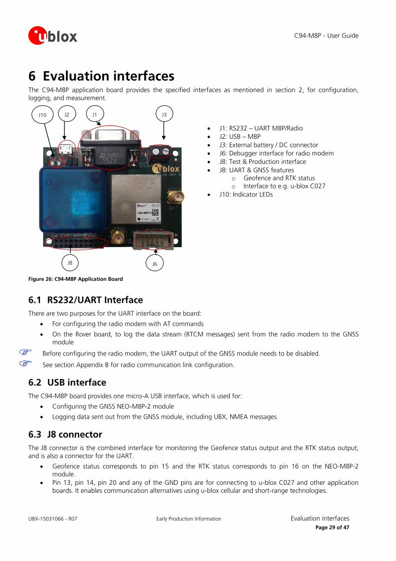
6 Evaluation interfaces The C94-M8P application board provides the specified interfaces as mentioned in section 2, for configuration,
logging, and measurement.
J1: RS232 – UART M8P/Radio
J2: USB – M8P
J3: External battery / DC connector
J6: Debugger interface for radio modem
J8: Test & Production interface
J8: UART & GNSS features o Geofence and RTK status
o Interface to e.g. u-blox C027
J10: Indicator LEDs
Figure 26: C94-M8P Application Board
6.1 RS232/UART Interface
There are two purposes for the UART interface on the board:
For configuring the radio modem with AT commands
On the Rover board, to log the data stream (RTCM messages) sent from the radio modem to the GNSS module
Before configuring the radio modem, the UART output of the GNSS module needs to be disabled.
See section Appendix B for radio communication link configuration.
6.2 USB interface
The C94-M8P board provides one micro-A USB interface, which is used for:
Configuring the GNSS NEO-M8P-2 module
Logging data sent out from the GNSS module, including UBX, NMEA messages.
6.3 J8 connector
The J8 connector is the combined interface for monitoring the Geofence status output and the RTK status output,
and is also a connector for the UART.
Geofence status corresponds to pin 15 and the RTK status corresponds to pin 16 on the NEO-M8P-2 module.
Pin 13, pin 14, pin 20 and any of the GND pins are for connecting to u-blox C027 and other application
boards. It enables communication alternatives using u-blox cellular and short-range technologies.
J8
J2 J1 J3
J6
J10

C94-M8P - User Guide
UBX-15031066 - R07 Early Production Information Evaluation interfaces
Page 30 of 47
The pin assignments of the 20-pin J8 connector are shown in Table 2. For more information, see the NEO-M8P Data Sheet [2].
Pin Nr. Assignment
1 V_BAT
2 GND
3 GND
4 RTK_STAT, monitor RTK status
5 GEOFENCE_STAT, monitor Geofence status
6 TIMEPULSE
7 GND
8 GND
9 RXD_GNSS
10 TXD_GNSS
11 GND
12 GND
13 RXD_EXT
14 TXD_EXT
15 GND
16 GND
17 SAFEBOOT_N
18 EXTINT
19 RESET_N
20 RADIO_OFF, apply 3.3 V to turn off the radio modem for external UART communication.
Table 2: Pin assignments of J8 connector
6.4 Battery connector
There is a 2-pin battery connector available on the C94-M8P for connecting the board to an external battery or DC
supply. This uses a standard 5.05 mm pitch 2-pin connector for supplying a 3.7-20 VDC source or external battery. The pin assignments of this 2-pin connector are shown in Table 3.
Pin Nr. Assignment
1 V_BAT, battery “+”
2 GND, battery “-”
Table 3: Pin assignments of battery connector
6.5 LED
The Blue LED (DS2), mounted on the C94-M8P application board, shows the time pulse output signal from the
NEO-M8P-2 module. The LED starts flashing one pulse per second during a GNSS fix. If there is no GNSS fix, the LED will light up without flashing.
The Green LED (DS1) indicates the RTK status. The LED flashes in float mode and stays on in fix mode. The LED is off
when there is no RTK fix.
6.6 Antenna connectors
6.6.1 Radio antenna connector
The radio antenna SMA connector on each board is used for connecting a UHF antenna. This connector is marked
with the text “UHF” on the board.

C94-M8P - User Guide
UBX-15031066 - R07 Early Production Information Evaluation interfaces
Page 31 of 47
6.6.2 GNSS antenna connector
The GNSS module SMA connector on each board is used to connect the external active GNSS antenna. This
connector is marked with the text “GNSS” on the board.
6.7 Wired serial RTCM3 connection between Base and Rover
To connect two C94 application boards without using the C94 radio modem a wired connection can be set up. The C94 radio modem needs to be disabled by applying 3.3V to the radio disable pin. This is important to prevent UART
interference.
C94-M8P-B PCB version
An external 3.3V source is needed. No voltage higher than 3.3V should be used.
Pin 13 on J8 needs to be pulled High to 3.3V
Pin 4 on J8 needs to be connected to the 3.3V source Ground.
C94-M8P-D PCB version
An external 3.3V source is needed. No voltage higher than 3.3V should be used.
Pin 20 of J8 needs to be pulled High to 3.3V
Pin 2 of J8 needs to be connected to the 3.3V source Ground.
Alternatively a hardware modification can be carried out. Refer to Appendix F.
The GNSS serial ports between the two C94 units need to be connected. Data is in one direction only from the Base to the Rover:
C94-M8P-B PCB version
Base C94 Pin 10 of J8 (TX_GNSS) connects to Rover C94 Pin 9 of J8 (RX_GNSS)
Base C94 Pin 3 of J8 (GND) connects to Rover C94 Pin 3 of J8 (GND)
C94-M8P-D PCB version
Base C94 Pin 10 J8 (TX_GNSS) connects to Rover C94 Pin 9 J8 (RX_GNSS)
Base C94 Pin 3 J8 (GND) connects to Rover C94 Pin 3 J8 (GND)
C94-M8P-B version shown above C94 -M8P-D/E version shown above

C94-M8P - User Guide
UBX-15031066 - R07 Early Production Information Block diagram
Page 32 of 47
7 Block diagram
Figure 27: Block diagram of the C94-M8P application board

C94-M8P - User Guide
UBX-15031066 - R07 Early Production Information Board layout
Page 33 of 47
8 Board layout
Figure 28: Board Layout of C94-M8P–D/E Application Board
C94-M8P - User Guide
UBX-15031066 - R07 Early Production Information Schematic
Page 34 of 47
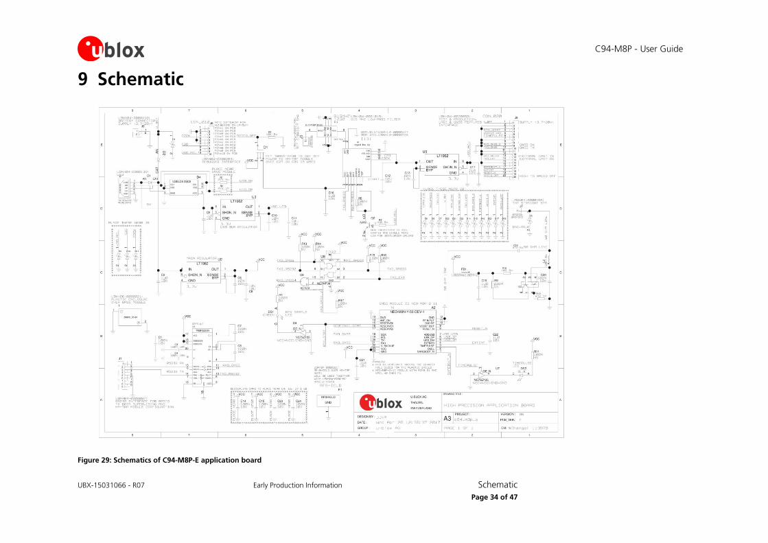
9 Schematic
Figure 29: Schematics of C94-M8P-E application board

C94-M8P - User Guide
UBX-15031066 - R07 Early Production Information Appendix
Page 35 of 47
Appendix
A Glossary Abbreviation Definition
BeiDou Chinese satellite system
ECEF Earth Center Earth Fixed format
GLONASS Russian satellite system
GND Ground
GNSS Global Navigation Satellite System
GPS Global Positioning System
MB Moving Baseline
PCB Printed circuit board
PLL Phase Locked Loop
PPS Pulse Per Second
QZSS Quasi-Zenith Satellite System
RAIM Receiver Autonomous Integrity Monitoring
RF Radio Frequency
RTCM Radio Technical Commission for Maritime Services
RTK Real Time Kinematic
TTFF Time To First Fix
UART Universal Asynchronous Receiver/Transmitter
Table 4: Explanation of abbreviations used
B Radio communication link configuration
Users do not need to make any configuration for the Radio communication link. The u-blox default
configurations are tested and verified.
Users need to take all responsibility for any changes against the default configuration.
By default, u-blox has configured the radio link module to meet local radio frequency requirements. The
C94-M8P application boards are labeled according to different radio modem variants as follows:
C94-M8P-1 for China
C94-M8P-2 for USA and Canada
C94-M8P-3 for Europe
C94-M8P-4 for Japan
The default radio-link configurations in shipped C94-M8P boards are listed below:

C94-M8P - User Guide
UBX-15031066 - R07 Early Production Information Appendix
Page 36 of 47
Parameters C94-M8P-1 for China C94-M8P-2 for USA/Canada C94-M8P-3 for Europe C94-M8P-4 for Japan
Minimum Frequency 433.180 MHz 902.5 MHz 433.230 MHz 922.8 MHz
Maximum Frequency 434.730 MHz 928.0 MHz 434.730 MHz 923.2 MHz
Air Speed 32 kbps 32 kbps 48 kbps 48 kbps
Serial baud rate 19.2 kbps 19.2 kbps 19.2kbps 19.2 kbps
TX Power 11 dBm 20 dBm 11 dBm 8 dBm
LBT_RSSI 0 0 71 78
Number of Channels 10 50 7 3
ECC 0 (off) 0 (off) 0 (off) 0 (off)
OpResend 0 (off) 0 (off) 0 (off) 0 (off)
Duty Cycle 100 % 100 % 20 % 100 %
Window width 66 66 66 66
MAVLink 0 0 0 0
Table 5: Default configuration for regional variants of the radio modem on C94-M8P application boards
The u-blox default configurations of the radio modem regional variants are tested and verified. Users need to
take all responsibility for any changes to the default configuration.
The C94-M8P application board uses a HM-TRP radio modem with SiK open source firmware, which supports a
subset variant of the Hayes “AT” modem commands for advance configuration.
Before configuring the radio modem, the GNSS module UART output needs to be disabled via u-center (View ->
Message View -> UBX-CFG-PRT), as shown in Figure 30. For more information, see the u-center User Guide [4],
and the u-blox 8 / u-blox M8 Receiver Description including Protocol Specification [1].
Figure 30: Disable UART output of NEO-M8P-2 GNSS module on C94-M8P application board
Use the serial-console application, Putty, on the PC to connect to the RS232/UART interface. Configure the serial
connection with baud rate 19200 Baud and COM port number assigned by Windows OS, as shown in Figure 31.
For more information about installing serial-console application, see chapter B.1.
Figure 31: Configuration of serial connection for Radio Modem on C94-M8P Application Board

C94-M8P - User Guide
UBX-15031066 - R07 Early Production Information Appendix
Page 37 of 47
Enable the AT command mode by sending sequence “+++” (quickly type “+++” and wait for 1 second) via the serial link. The radio modem sends “OK” to indicate entering the AT command mode.
Figure 32: Radio modem sends “OK” prompt through serial link when AT Command Mode is Enabled
In AT command mode, the radio modem accepts AT commands and gives response correspondingly. In case of wrong AT commands, the radio modem returns ERROR as the response.
Figure 33: Send AT commands to Radio Modem
Table 6 shows the AT command set that is supported by the C94-M8P application board.
Table 7 shows all radio parameters that are configurable. For more information about configuring the radio
modem used by C94-M8P, see http://copter.ardupilot.com/wiki/common-3dr-radio-advanced-configuration-and-technical-information/.
UHF operation needs to be on licensed bands according to regions.
Remember to enable GNSS module UART output on Base when finished with radio communication link configuration.
Un-plug any serial connection from the 9 Pin D-type serial connector otherwise there can be interuption of
the serial link between the M8P and C94 radio.

C94-M8P - User Guide
UBX-15031066 - R07 Early Production Information Appendix
Page 38 of 47
Commands Description
ATI Shows radio version
ATI2 Shows board type
ATI3 Shows board frequency
ATI4 Shows board version
ATI5 Shows radio parameters and the current settings.
ATI6 Displays timing report of TDM
ATI7 Displays signal report of RSSI
ATO Exits from AT command mode
ATS<n>? Displays radio parameter indicated by index number “<n>“. “<n>“ needs to specify by a user, which is listed in output of command ATI5.
ATS<n>=<X> Set radio parameter indexed by <n> to “<X>“. “<n>“ and “<X>“ need to specify by a user. “<n>“ is listed in output of command ATI5.
ATZ Reboots the radio modem
AT&W Writes the current parameters to EEPROM
AT&F Resets all parameters to default factory settings
AT&T=RSSI Enables debug reporting of RSSI
AT&T=TDM Enables debug reporting of TDM
AT&T Disables all debug reporting
Table 6: AT Command Set for Radio Modem on C94-M8P application board
Index<n> Parameter Name Description
1 SERIAL_SPEED Serial speed in “one byte form”, e.g. 19 corresponds to 19200 Bd configured for the C94-M8P board.
2 AIR_SPEED Air data rate in “one byte form”. Must be same for a pair of radios.
3 NETID Network ID. Must be same for the pair of C94-M8P boards. Must be same for a pair of radios.
4 TXPOWER Transmit power in dBm, maximum value is 20 dBm.
5 ECC Enables / disables the golay error correcting code. Must be same for a pair of radios.
6 MAVLINK Configure MAVLink framing and reporting,
0: no mavlink (default)
1: frame mavlink
2: low latency mavlink
8 MIN_FREQ Minimum frequency in kHz. Must be same for a pair of radios.
9 MAX_FREQ Maximum frequency in kHz. Must be same for a pair of radios.
10 NUM_CHANNELS Number of frequency hopping channels. Must be same for a pair of radios.
11 DUTY_CYCLE Percentage of time to allow transmit
12 LBT_RSSI Threshold of Listen Before Talk. Must be same for a pair of radios.
15 MAX_WINDOW Maximum transmitting window in ms,
default: 66ms
for low latency: 33ms
Must be same for a pair of radios.
Table 7: Configurable radio parameters
B.1 Serial console terminal installation Many serial console terminal programs are available, either as commercial software or from open source communities. In this user guide, the examples show the Putty terminal emulator running on Windows 7. Putty is
an open source stand-alone application that runs on multiple operating systems. Download and uncompress the
software package from http://www.putty.org, and then run the executable file.
For more information about Putty, see http://www.putty.org.

C94-M8P - User Guide
UBX-15031066 - R07 Early Production Information Appendix
Page 39 of 47
C Updating C94 radio modem firmware To operate moving baseline RTK with a 1 Hz update rate the latest production radio firmware must be used.
Refer to Table 8 to see if your PCB version needs to be updated.
Updating firmware on the C94 radio requires a Silicon Labs EC2 or EC3 USB debugger adapter. It is
recommended to use the Silicon Labs command line tool FlashUtilCL.exe. It is included with a software package
“FLASHUtil Installer”. You can download it from http://www.silabs.com/support/resources.ct-software.p-microcontrollers.p-wireless and search for FLASHUtil Installer.
PCB version Type Number C94-M8P-1 C94-M8P-2 C94-M8P-3 C94-M8P-4
PCB C94-M8P-B C94-M8P-X-00 Yes Yes Yes N/A
PCB C94-M8P-D and M8P FW = HPG1.20 or lower
C94-M8P-X-10 Yes Yes Yes
Yes
PCB C94-M8P-D and M8P FW = HPG1.30
C94-M8P-X-10 No No No
No
PCB C94-M8P-E C94-M8P-X-11 No No No No
Table 8: Radio firmware update requirements for a moving baseline. “M8P FW” refers to the FW received originally on the M8P.
C94-M8P-1 C94-M8P-2 C94-M8P-3 C94-M8P-4
HM_TRP_006_01 HM_TRP_006_02 HM_TRP_007_03 HM_TRP_TEST_007_04
Table 9: Current production C94 radio modem firmware versions.
For units C94-M8P-X-10 (PCB C94-M8P-D) that were delivered with M8P FW HPG1.20 or lower the radio will
report software versions as shown in Table 10 below:
C94-M8P-1 C94-M8P-2 C94-M8P-3 C94-M8P-4
SiK 1.9 on HM_TRP SiK 1.9 on HM_TRP FW_HM_TRP_006_03 FW_HM_TRP_TEST_006_04
Table 10: C94-M8P-X-10 radio firmware versions with HPG1.20 or lower
Figure 34: Silicon Labs USB debugger adapter

C94-M8P - User Guide
UBX-15031066 - R07 Early Production Information Appendix
Page 40 of 47
C.1 Updating procedure
Please download the correct firmware for your C94 variant from the u-blox GitHub website: https://github.com/u-blox/C94-application-board-radio-firmware/
There are two parts to the firmware, a Boot loader (BL) and the Firmware itself (FW).
1. Copy the C94 radio boot loader (BL) and firmware (FW) in the same folder as the Flash utility. For
example with C94-M8P-4 the correct FW is -4 version. Example of the file names:
BL_HM_TRP_006_04_083b97ece14eadc219bda775c5a6ccb07cfe9baf.hex
FW_HM_TRP_006_04_489d3e8fbb1663f253bc49d2d32794350eaa8749.hex
2. Connect the Silicon Labs debugger directly into C94 debugger interface for radio modem (J6). Note the Pin 1 location on the C94 board and the Pin 1 location on the debugger connector. The debugger will
power the C94 so no need to plug in a USB cable or any other power.
3. Connect the Silicon Labs debugger to a USB port on your computer 4. Open a command prompt in the folder where the Flash utility is.
5. For this example (a -4 radio) enter the following:
FlashUtilCL.exe downloadusb –E BL_HM_TRP_006_04_083b97ece14eadc219bda775c5a6ccb07cfe9baf.hex "" 0 1
Figure 35: Using the FlashUtilCL in Windows Command Prompt
6. The Silicon Labs Debugger will power the radio from the USB port once the command is executed. You
will see the Power and RUN/STOP LED's on the debugger light up as it is running and programming. The Flash utility will then exit if it has been successful. You might need to repeat this command if the PC did
not connect properly to the debugger.
7. Repeat the process for the firmware (FW):
FlashUtilCL.exe downloadusb –E FW_HM_TRP_006_04_489d3e8fbb1663f253bc49d2d32794350eaa8749.hex "" 0 1
8. The Debugger lights will again light up as it is programming the radio and the flash utility will then exit
if it has been successful. You might need to repeat this command if the PC did not connect properly to
the debugger.
9. The C94 radio will need a power cycle, if you have powered the radio through the debugger it will
power it off once completed. If you have the USB cable connected, remove it and connect it again.
The next step is to verify that the Radio modem runs with the new firmware. Power up the C94 board and verify
that the Green LED on the radio modem lights up. It will flash slowly if no other C94 radio connects to it. For the C94 version with a shield over the radio, simply lift off the shield. Refer to Figure 37 to see the location of the
LEDs on the radio modem. If the Green LED lights up all went well.
To verify the current radio firmware serial port speed, refer to Appendix B how to configure the radio. When connected with your terminal software, enter ATI5 and then ATI to check the firmware version.

C94-M8P - User Guide
UBX-15031066 - R07 Early Production Information Appendix
Page 41 of 47
Figure 36: Verifying radio firmware version
Finally, remember to enable the GNSS module UART output when finished with radio communication link
configuration. See Figure 7 and Figure 8. Ensure you also unplug any serial connection to the 9 Pin D-Type serial connector as this can interfere with the communication between the radio and the M8P. Re-power the C94 to
ensure the radio starts in data mode. Then ensure the M8P is using the same UART baud rate.
D Notes on FW3.01 HPG1.40 Users should note the following points when using HPG1.40:
Multiple base stations sharing the same network ID is not supported.
High multipath and poor or no ground planes and low signal levels on the Base or Rover will prevent the
Rover entering Fixed mode. An active GNSS antenna is required.
Do not enable both MSM7 and MSM4. Moving baseline is only supported with MSM7.
E Notes on hardware Users should refer to Table 8 and Table 9 to identify a particular variant:
E.1 For C94 radio firmware not in current production low latency firmware as indicated in Table 9:
The radio link latency of the C94 application board can extend up to 550 ms for a message content of 2 k bits, i.e. with MSM7 messages, this payload size would represent about 12 satellites, e.g. 6 GPS and 6 GLO - a fairly
typical scenario. Hence standard RTK update rates beyond 1 Hz should be contemplated carefully owing to the
radio modem latency; operating above 1 Hz might not be possible without affecting RTK performance. In any event, the modem interface rate of 9600 baud will present a hard limit depending on the number of satellites
and navigation update rate of the Base.
However it is allowable for the Rover to run at a rate of higher than 1 Hz if required limited to 5 Hz Dual constellation and 8 Hz GPS only. With a Base Navigation Rate setting of 1 Hz the RTCM3 update of 1 Hz will not
affect the Rover accuracy. This option is not allowable in moving baseline as this mode requires the Base and
Rover to use identical Navigation Rates.
Moving baseline operation at 1 Hz with this older radio firmware is not supported due to the latency. The radio
firmware should be updated to the latest production firmware. If you wish to use the moving baseline feature

C94-M8P - User Guide
UBX-15031066 - R07 Early Production Information Appendix
Page 42 of 47
without the radio in a application with a wired connection for the RTCM3 data, the NEO-M8P with FW HPG1.40 supports higher update rates of 4 Hz at 115200 baud.
E.2 For C94 radio firmware that is current production low latency firmware as indicated in Table 9:
This delay optimized radio firmware allows 1 Hz moving baseline operation. With standard RTK and applications
requiring higher than 1 Hz operation, it is recommended that the Rover runs at a rate of higher than 1 Hz. This
would be limited to 5 Hz Dual constellation and 8 Hz GPS only. While the Base runs at a Nav Rate of 1 Hz only. The RTCM3 update of 1 Hz will not affect the Rover accuracy. This is not supported in moving baseline as this
mode requires the Base and Rover to be at the same Navigation Rate. The modem interface speed of 19200
baud also presents a hard limit depending on the number of satellites and Navigation update rate of the Base. If you wish to use the moving baseline feature without the radio in a application with a wired connection for the
RTCM3 data, the M8P (FW HPG1.40 only) supports higher update rates of 4 Hz at 115200 baud.
E.3 C94 Variants -00 Variants using the old board version (C94-M8P-1-00, C94-M8P-2-00 and C94-M8P-3-00) have a different board
layout than the C94P-M8P-X-10 versions. This chapter describes the C94P-M8P-X-00 versions and how they
differ from the newer versions.
E.3.1 Overview
There is no RF-shield attached on the top of the radio modem and no plastic enclosure is attached on the top of the GNSS module.
E.3.2 Connectors
J1: RS232 – UART M8P/Radio
J2: USB – M8P
J3: External battery / DC connector
J4: Interface to u-blox C027
J6: Debugger interface for radio modem
J8: Test & Production interface
J9: Geofence and RTK status
J10: Indicator LEDs
Figure 37: C94-M8P Application Board
J4
J2 J1 J3
J6 J10 J9
J8

C94-M8P - User Guide
UBX-15031066 - R07 Early Production Information Appendix
Page 43 of 47
J9 connector
The J9 connector is the monitor interface for the Geofence status and the RTK status, which correspond to pin
15 and pin 16 on the NEO-M8P-2 module. Table 11 shows the pin assignments of this 2-pin connector. For
more information, refer to the NEO-M8P Data Sheet [2].
Pin Nr. Assignment
1 GEOFENCE_STAT, monitor Geofence status
2 RTK_STA, monitor RTK status
Table 11: Pin assignments of J9
J4 connector
The J4 connector is the interface for connecting to u-blox C027 and other application boards. It enables communication alternatives using u-blox cellular and short-range technologies. The pin assignments of this 4-pin
connector are shown in Table 12. For more details about C027, see https://www.u-blox.com/product/c027.
Table 12: Pin assignments of J4
LEDs
Four indicator LEDs are mounted on the C94-M8P application board:
The Blue LED shows the time pulse output signal from the NEO-M8P-2 module. The LED starts flashing
one pulse per second during a GNSS fix. If there is no GNSS fix, the LED will light up without flashing.
The Yellow LED indicates geofence status
The Red LED flashes when the radio modem is transmitting
The Green LED blinks when radio modem is ready to receive
E.3.3 Dimensions
Dimensions between screw holes on the older board are 69.6 and 48.2 mm.
Pin Nr. Assignment
1 GND
2 TXD
3 RXD
4 3.3 v

C94-M8P - User Guide
UBX-15031066 - R07 Early Production Information Appendix
Page 44 of 47
F Hardware modification Optionally one can carry out a wire modification to link a 3.3V source on the C94 PCB to the radio disable pin. A
wire link needs to be soldered from a capacitor to the corresponding pin on connector J8. This capacitor and J8
connector are located differently depending on the PCB version of C94 used.
For the C94-M8P-B:
Figure 38: C94-M8P-B radio disable modification
Capacitor C9 positive terminal (indicated by the short red line in Figure 38) needs to be connected to J8 Pin 13.
Solder a short wire link between the two points indicated by the arrows.
Pin 13

C94-M8P - User Guide
UBX-15031066 - R07 Early Production Information Appendix
Page 45 of 47
For the C94-M8P-D and the C94-M8P-E:
Figure 39: C94-M8P-D/E radio disable modification
The plastic cover over the M8P needs to be removed first to gain access to the capacitor C9. Unscrew the two
screws holding the plastic cover held in place by screws accessible from the bottom of the PCB. The two black arrows on the corners of the rectangular plastic cover indicate these screw locations. Solder a short wire
between the positive end of C9 (indicated by a short red line) and J8 Pin 20. This is shown by the red circles and
blue arrows above. If a corresponding slot for the wire link is cut in the plastic cover, it can be replaced carefully by aligning the screw holes and replacing the screws from the bottom. The plastic cover ensures that any rapid
temperature variations from air currents do not affect the M8P stability.
Pin 20

C94-M8P - User Guide
UBX-15031066 - R07 Early Production Information Appendix
Page 46 of 47
Related documents [1] u-blox 8 / u-blox M8 Receiver Description Including Protocol Specification (Public version), Docu. No. UBX-
13003221
[2] NEO-M8P Data Sheet, Docu. No. UBX-15016656
[3] NEO-M8P Hardware Integration Manual, Docu. No. UBX-15028081
[4] u-center User Guide, Docu. No. UBX-13005250
[5] Achieving Centimeter Level Performance with Low Cost Antennas, Docu. No. UBX-16010559
For regular updates to u-blox documentation and to receive product change notifications, register on our homepage (http://www.u-blox.com)
Revision history Revision Date Name Status / Comments
R01 19-Feb-2016 yzha Advance Information
R02 30-May-2016 jhak Restructuring chapters, more details on Base/Rover configuration, FW3.01 HPG1.11 related information
R03 19-Aug-2016 jhak Updated package contents, more details on GNSS antenna considerations and setting up RTCM messages
R04 14-Oct-2016 jhak HPG1.20 update. Added chapter D Notes on Hardware
R05 08-Dec-2016 jhak HPG1.30 update. Merged all variants into one user guide
R06 01-Feb-2017 jhak Updated board layout picture and radio settings
R07 07-Jul-2017 jhak/ghun HPG1.40 update including support for moving baseline and instructions how to update C94 radio modem firmware

C94-M8P - User Guide
UBX-15031066 - R07 Early Production Information Contact
Page 47 of 47
Contact For complete contact information, visit us at www.u-blox.com
u-blox Offices
North, Central and South America
u-blox America, Inc.
Phone: +1 703 483 3180
E-mail: [email protected]
Regional Office West Coast:
Phone: +1 408 573 3640
E-mail: [email protected]
Technical Support:
Phone: +1 703 483 3185
E-mail: [email protected]
Headquarters Europe, Middle East, Africa
u-blox AG
Phone: +41 44 722 74 44 E-mail: [email protected]
Support: [email protected]
Asia, Australia, Pacific
u-blox Singapore Pte. Ltd.
Phone: +65 6734 3811
E-mail: [email protected] Support: [email protected]
Regional Office Australia:
Phone: +61 2 8448 2016 E-mail: [email protected]
Support: [email protected]
Regional Office China (Beijing):
Phone: +86 10 68 133 545 E-mail: [email protected]
Support: [email protected]
Regional Office China (Chongqing):
Phone: +86 23 6815 1588
E-mail: [email protected]
Support: [email protected]
Regional Office China (Shanghai):
Phone: +86 21 6090 4832
E-mail: [email protected]
Support: [email protected]
Regional Office China (Shenzhen):
Phone: +86 755 8627 1083
E-mail: [email protected]
Support: [email protected]
Regional Office India:
Phone: +91 80 4050 9200
E-mail: [email protected] Support: [email protected]
Regional Office Japan (Osaka):
Phone: +81 6 6941 3660 E-mail: [email protected]
Support: [email protected]
Regional Office Japan (Tokyo):
Phone: +81 3 5775 3850 E-mail: [email protected]
Support: [email protected]
Regional Office Korea:
Phone: +82 2 542 0861
E-mail: [email protected]
Support: [email protected]
Regional Office Taiwan:
Phone: +886 2 2657 1090
E-mail: [email protected] Support: [email protected]