Embed Size (px)
Citation preview
1
Aug. 2017
Izumi MIKAMI, Koki ASARI, and Masayuki SAITO
Satellite Positioning Research & Application Center(SPAC)
General Incorporated Foundation of Japan
Bridging between RTK and PPP-RTK
to Develop New Survey Period
14th South East Asia Survey Congress
15-17 August 2017
Brunei Darussalam
2
Study motivation and abstract
1. Cabinet Office of Japan will launch 3 QZS in 2017, and continuous service by
4 satellite constellation will start form April, 2018 . This service is expected to
spread to South East Asia in the near future.
2. SPAC has been servicing cm class augmentation, named CMAS, for QZSS
demonstration purpose mainly in Japan for past 6 years, and strongly
supporting Japanese industry to utilize QZSS service, including cm class SSR
augmentation carried by L6 from QZSS. This can service any number of users
within 60kmX60km area by one set of augmentation data broadcasting.
3. SSR augmentation and its positioning method, PPP-RTK, seem still unfamiliar
to RTK users as well as non-professional people. For easier understanding of
PPP-RTK, we decided to clarify physical meaning of the method using
simplified diagrams and comparison with RTK.
4. The understanding above gave us a hint to develop “L6 Adaptor” which
receives CLAS/SSR augmentation data and drives existing RTK receivers with
cm class accuracy. This feature is expanded to new service on smartphones.
CMAS: Centi-Meter-class Augmentation System
QZSS: Quasi-Zenith Satellite System
SSR: State Space Representation
RTK: Real Time Kinematic
PPR-RTK: Precise Point Positioning in RTK networks
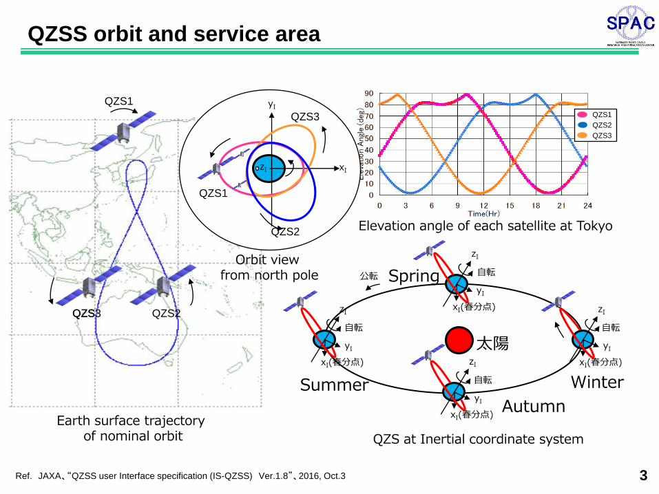
QZS at Inertial coordinate system
Ref. JAXA、“QZSS user Interface specification (IS-QZSS) Ver.1.8”、2016, Oct.3 3
Earth surface trajectory of nominal orbit
Elevation angle of each satellite at Tokyo
公転 自転 Spring
xI(春分点)
yI
zI
Summer
xI(春分点)
yI
zI
自転
Autumn xI(春分点)
yI
zI
自転 Winter
xI(春分点)
yI
zI
自転
太陽
QZS1
QZS QZS3 QZS2
yI
zI xI
QZS1
QZS3
QZS2
QZS1
QZS2
QZS3
Orbit view from north pole
QZSS orbit and service area
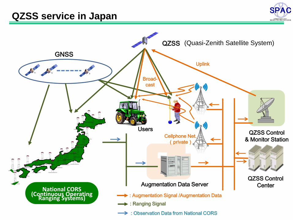
QZSS Control
Center National CORS
(Continuous Operating Ranging Systems)
Augmentation Data Server
QZSS service in Japan
: Augmentation Signal /Augmentation Data
: Ranging Signal
: Observation Data from National CORS
QZSS
GNSS
Uplink
Users QZSS Control
& Monitor Station Cellphone Net.
(private)
Broad-
cast
(Quasi-Zenith Satellite System)
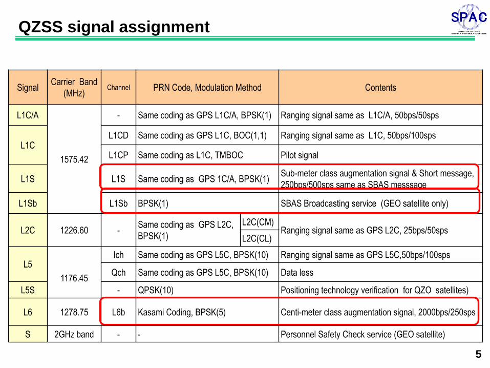
Signal Carrier Band
(MHz) Channel PRN Code, Modulation Method Contents
L1C/A
1575.42
- Same coding as GPS L1C/A, BPSK(1) Ranging signal same as L1C/A, 50bps/50sps
L1C L1CD Same coding as GPS L1C, BOC(1,1) Ranging signal same as L1C, 50bps/100sps
L1CP Same coding as L1C, TMBOC Pilot signal
L1S L1S Same coding as GPS 1C/A, BPSK(1) Sub-meter class augmentation signal & Short message,
250bps/500sps same as SBAS messsage
L1Sb L1Sb BPSK(1) SBAS Broadcasting service (GEO satellite only)
L2C 1226.60 - Same coding as GPS L2C,
BPSK(1)
L2C(CM) Ranging signal same as GPS L2C, 25bps/50sps
L2C(CL)
L5
1176.45
Ich Same coding as GPS L5C, BPSK(10) Ranging signal same as GPS L5C,50bps/100sps
Qch Same coding as GPS L5C, BPSK(10) Data less
L5S - QPSK(10) Positioning technology verification for QZO satellites)
L6 1278.75 L6b Kasami Coding, BPSK(5) Centi-meter class augmentation signal, 2000bps/250sps
S 2GHz band - - Personnel Safety Check service (GEO satellite)
5
QZSS signal assignment
6
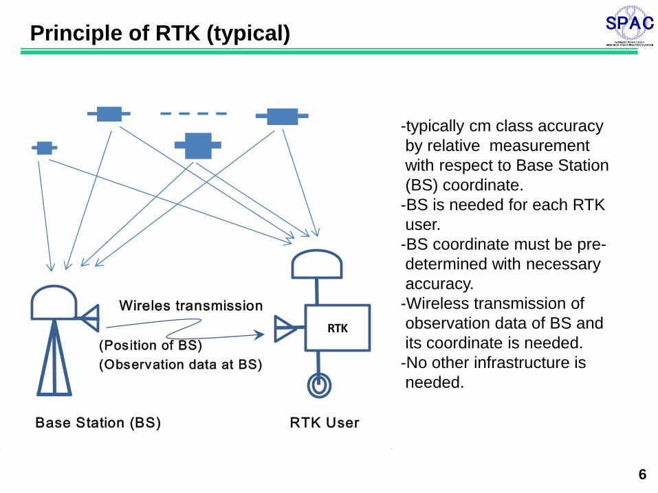
Principle of RTK (typical)
(Position of BS)
(Observation data at BS)
Base Station (BS) RTK User
Wireles transmission
RTK
-typically cm class accuracy
by relative measurement
with respect to Base Station
(BS) coordinate.
-BS is needed for each RTK
user.
-BS coordinate must be pre-
determined with necessary
accuracy.
-Wireless transmission of
observation data of BS and
its coordinate is needed.
-No other infrastructure is
needed.
7
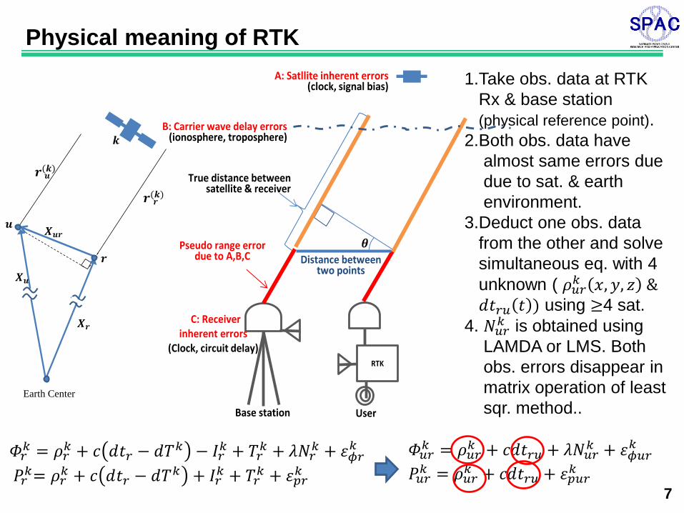
Physical meaning of RTK
Earth Center
1.Take obs. data at RTK
Rx & base station
(physical reference point).
2.Both obs. data have
almost same errors due
due to sat. & earth
environment.
3.Deduct one obs. data
from the other and solve
simultaneous eq. with 4
unknown ( 𝜌𝑢𝑟𝑘 𝑥, 𝑦, 𝑧 &
𝑑𝑡𝑟𝑢 𝑡 ) using ≥4 sat.
4. 𝑁𝑢𝑟𝑘 is obtained using
LAMDA or LMS. Both
obs. errors disappear in
matrix operation of least
sqr. method..
𝛷𝑟𝑘 = 𝜌𝑟
𝑘 + 𝑐 𝑑𝑡𝑟 − 𝑑𝑇𝑘 − 𝐼𝑟𝑘 + 𝑇𝑟
𝑘 + 𝜆𝑁𝑟𝑘 + 𝜀𝜙𝑟
𝑘
𝑃𝑟𝑘= 𝜌𝑟
𝑘 + 𝑐 𝑑𝑡𝑟 − 𝑑𝑇𝑘 + 𝐼𝑟𝑘 + 𝑇𝑟
𝑘 + 𝜀𝑝𝑟𝑘
𝛷𝑢𝑟𝑘 = 𝜌𝑢𝑟
𝑘 + 𝑐𝑑𝑡𝑟𝑢 + 𝜆𝑁𝑢𝑟𝑘 + 𝜀𝜙𝑢𝑟
𝑘
𝑃𝑢𝑟𝑘 = 𝜌𝑢𝑟
𝑘 + 𝑐𝑑𝑡𝑟𝑢 + 𝜀𝑝𝑢𝑟𝑘
RTK
Pseudo range error due to A,B,C
True distance between satellite & receiver
C: Receiver inherent errors
(Clock, circuit delay)
UserBase station
Distance between two points
B: Carrier wave delay errors(ionosphere, troposphere)
A: Satllite inherent errors(clock, signal bias)
8
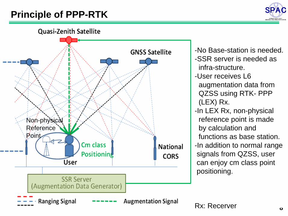
-No Base-station is needed.
-SSR server is needed as
infra-structure.
-User receives L6
augmentation data from
QZSS using RTK- PPP
(LEX) Rx.
-In LEX Rx, non-physical
reference point is made
by calculation and
functions as base station.
-In addition to normal range
signals from QZSS, user
can enjoy cm class point
positioning.
Rx: Recerver
Principle of PPP-RTK
Non-physical
Reference
Point
9
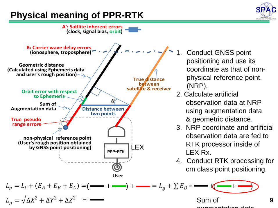
Physical meaning of PPR-RTK
1. Conduct GNSS point
positioning and use its
coordinate as that of non-
physical reference point.
(NRP).
2. Calculate artificial
observation data at NRP
using augmentation data
& geometric distance.
3. NRP coordinate and artificial
observation data are fed to
RTK processor inside of
LEX Rx.
4. Conduct RTK processing for
cm class point positioning.
LEX RTK-PPP
Sum of Augmentation data Distance between
two points
non-physical reference point(User's rough position obtained
by GNSS point positioning)
True pseudorange errors
Geometric distance (Calculated using Ephemeris data
and user's rough position)
Orbit error with respect to Ephemeris
True distance between
satellite & receiver
A': Satllite inherent errors(clock, signal bias, orbit)
B: Carrier wave delay errors(ionosphere, troposphere)
User
PPP-RTK
= +( + ) =( + ) +
= Sum of
augmentation data
10
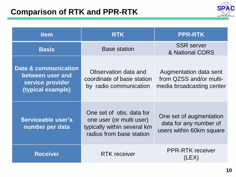
Comparison of RTK and PPR-RTK
item RTK PPR-RTK
Basis Base station SSR server
& National CORS
Data & communication
between user and
service provider
(typical example)
Observation data and
coordinate of base station
by radio communication
Augmentation data sent
from QZSS and/or multi-
media broadcasting center
Serviceable user’s
number per data
One set of obs. data for
one user (or multi user)
typically within several km
radius from base station
One set of augmentation
data for any number of
users within 60km square
Receiver RTK receiver PPR-RTK receiver
(LEX)
11
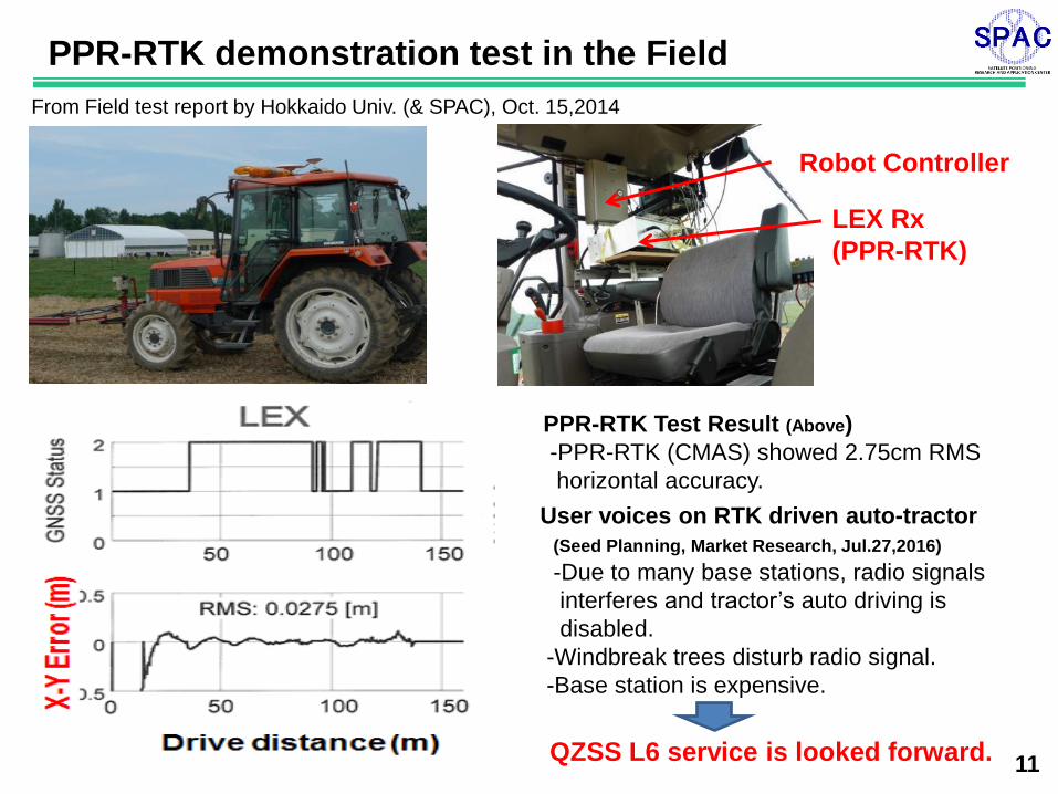
PPR-RTK demonstration test in the Field
From Field test report by Hokkaido Univ. (& SPAC), Oct. 15,2014
LEX Rx
(PPR-RTK)
Robot Controller
QZSS L6 service is looked forward.
PPR-RTK Test Result (Above)
-PPR-RTK (CMAS) showed 2.75cm RMS
horizontal accuracy.
User voices on RTK driven auto-tractor
(Seed Planning, Market Research, Jul.27,2016)
-Due to many base stations, radio signals
interferes and tractor’s auto driving is
disabled.
-Windbreak trees disturb radio signal.
-Base station is expensive.
12
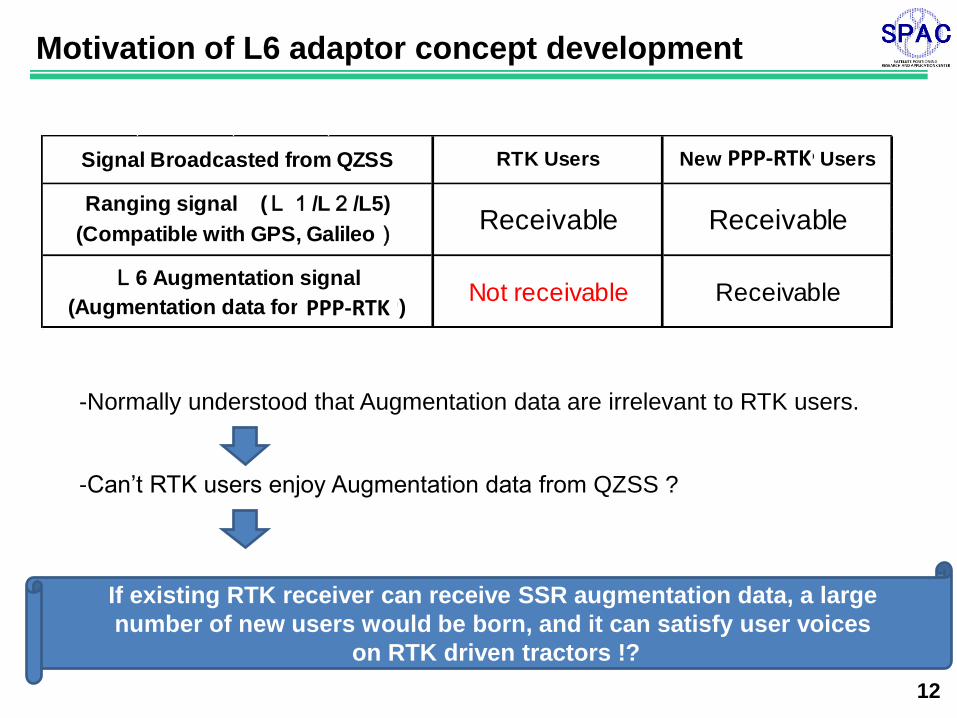
Motivation of L6 adaptor concept development
-Normally understood that Augmentation data are irrelevant to RTK users.
-Can’t RTK users enjoy Augmentation data from QZSS ?
If existing RTK receiver can receive SSR augmentation data, a large
number of new users would be born, and it can satisfy user voices
on RTK driven tractors !?
L6 Augmentation signal
(Augmentation data for RTK-PPP)Not receivable Receivable
Signal Broadcasted from QZSS RTK Users New RTK-PPP Users
Ranging signal (L1/L2/L5)
(Compatible with GPS, Galileo)Receivable Receivable
PPP-RTK
PPP-RTK
13
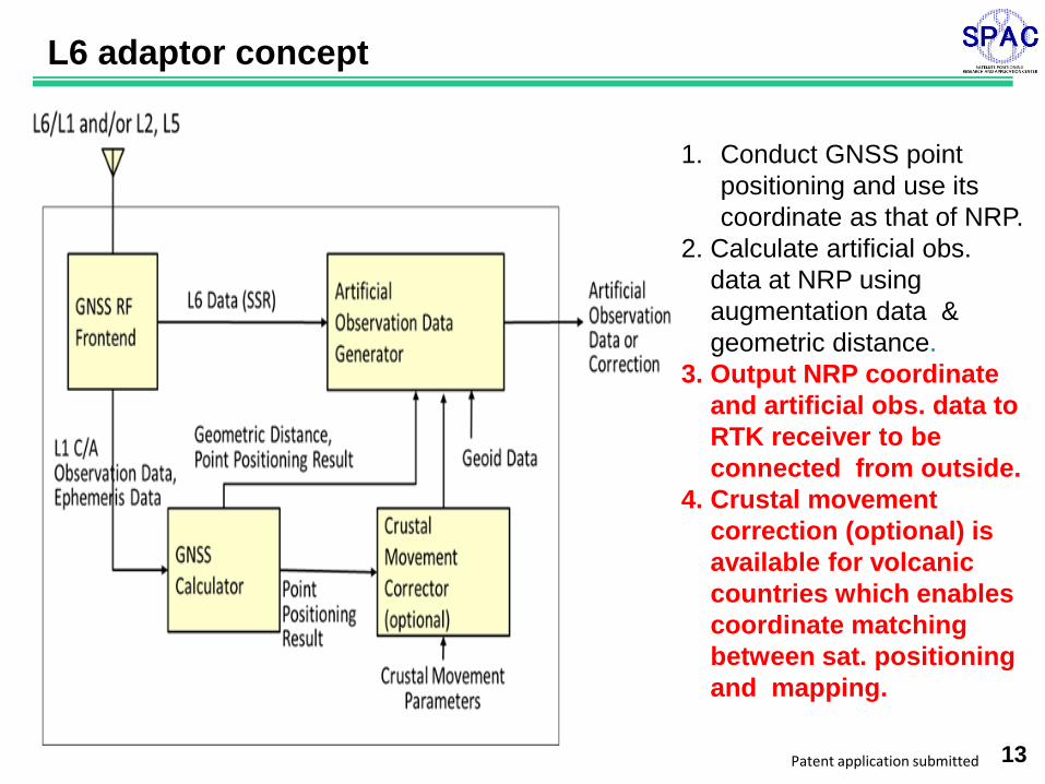
L6 adaptor concept
1. Conduct GNSS point
positioning and use its
coordinate as that of NRP.
2. Calculate artificial obs.
data at NRP using
augmentation data &
geometric distance.
3. Output NRP coordinate
and artificial obs. data to
RTK receiver to be
connected from outside.
4. Crustal movement
correction (optional) is
available for volcanic
countries which enables
coordinate matching
between sat. positioning
and mapping.
Patent application submitted
14
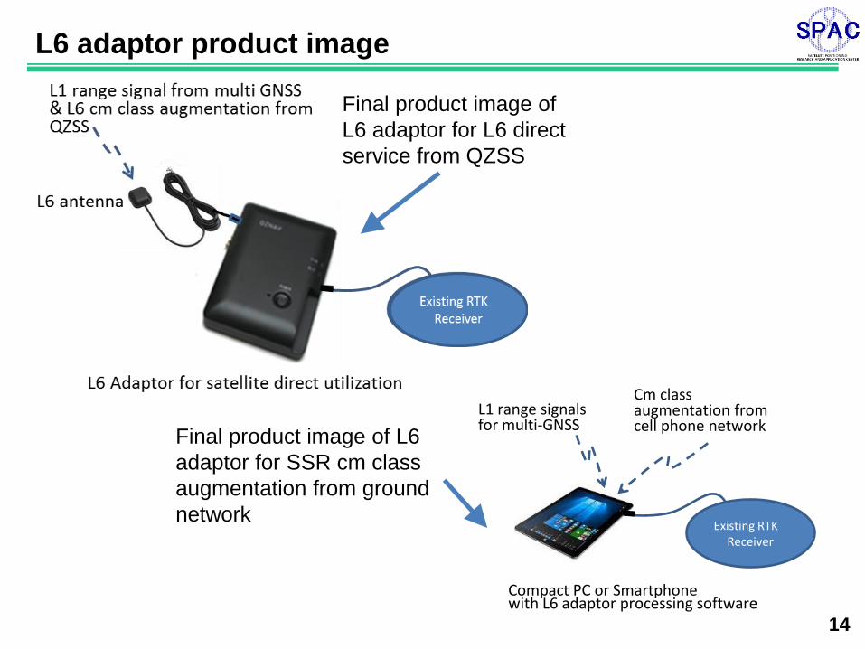
L6 adaptor product image
Final product image of
L6 adaptor for L6 direct
service from QZSS
Final product image of L6
adaptor for SSR cm class
augmentation from ground
network Existing RTK
Receiver
Compact PC or Smartphone with L6 adaptor processing software
Cm class augmentation from cell phone network
L1 range signals for multi-GNSS
15
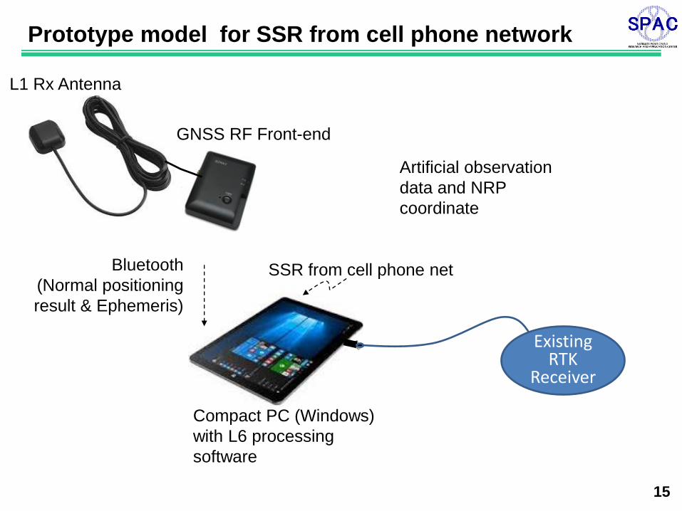
Prototype model for SSR from cell phone network
Bluetooth
(Normal positioning
result & Ephemeris)
GNSS RF Front-end
Compact PC (Windows)
with L6 processing
software
L1 Rx Antenna
SSR from cell phone net
Artificial observation
data and NRP
coordinate
Existing RTK
Receiver
16
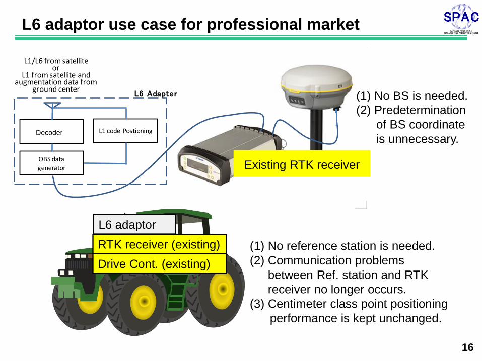
L6 adaptor use case for professional market
L6 adaptor
RTK receiver (existing)
Drive Cont. (existing)
(1) No reference station is needed.
(2) Communication problems
between Ref. station and RTK
receiver no longer occurs.
(3) Centimeter class point positioning
performance is kept unchanged.
L6 Adapter
DEC
OBS data generator
L1 code Postioning
L1/L6 from satelliteor
L1 from satellite and augmentation data from
ground center
Decoder
Existing RTK receiver
(1) No BS is needed.
(2) Predetermination
of BS coordinate
is unnecessary.
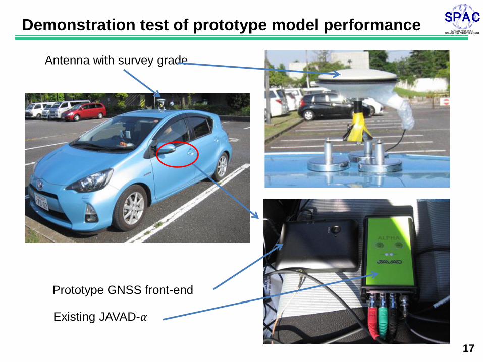
17
Demonstration test of prototype model performance
Antenna with survey grade
Prototype GNSS front-end
Existing JAVAD-𝛼
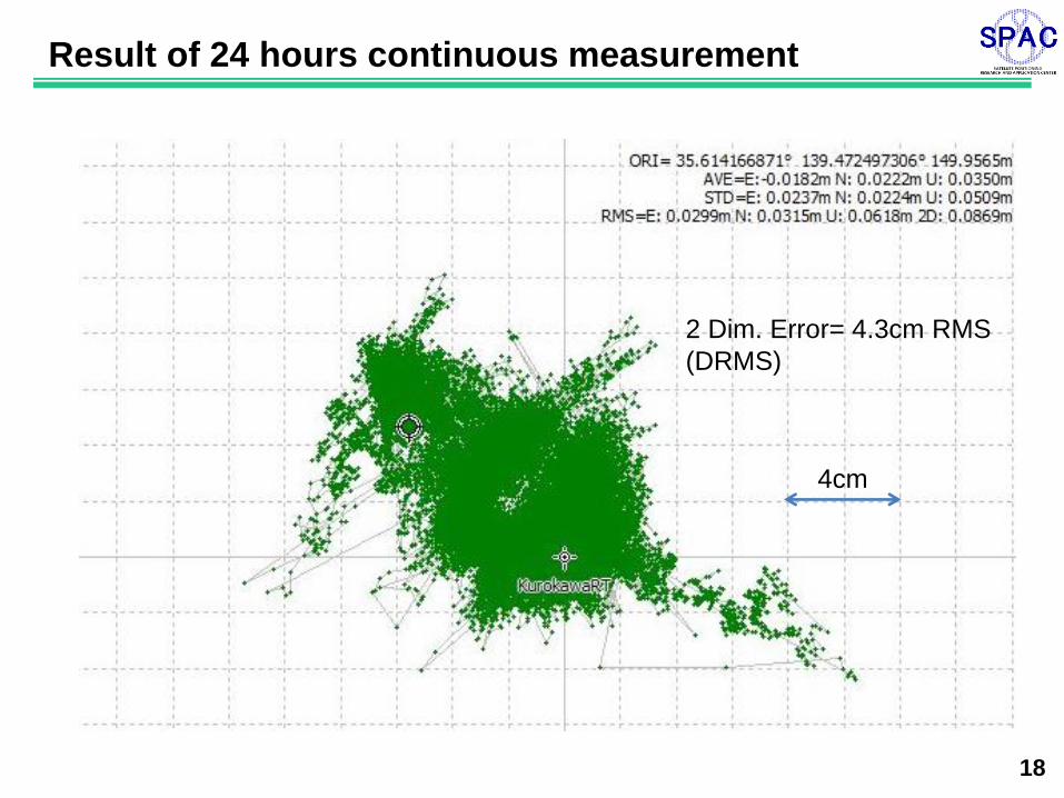
18
Result of 24 hours continuous measurement
4cm
2 Dim. Error= 4.3cm RMS
(DRMS)
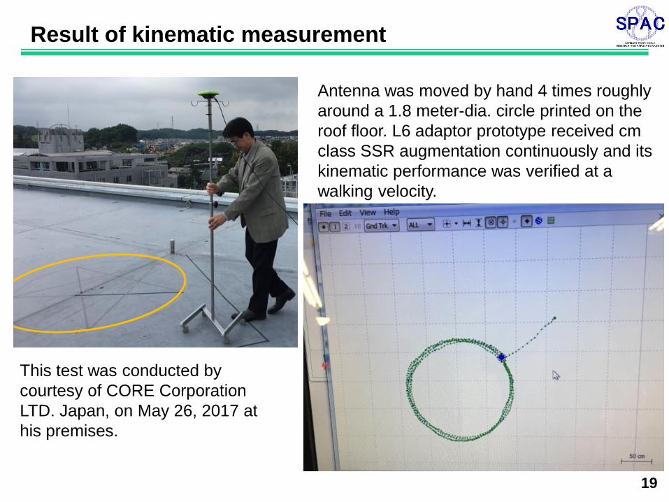
19
Result of kinematic measurement
This test was conducted by
courtesy of CORE Corporation
LTD. Japan, on May 26, 2017 at
his premises.
Antenna was moved by hand 4 times roughly
around a 1.8 meter-dia. circle printed on the
roof floor. L6 adaptor prototype received cm
class SSR augmentation continuously and its
kinematic performance was verified at a
walking velocity.
20
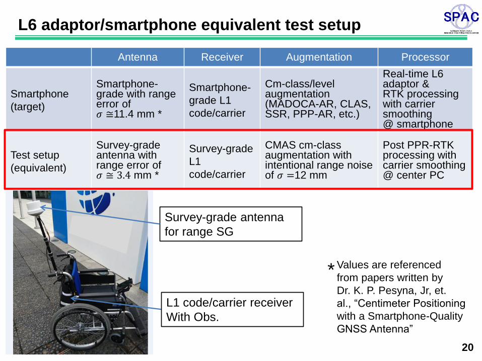
L6 adaptor/smartphone equivalent test setup
Antenna Receiver Augmentation Processor
Smartphone
(target)
Smartphone-grade with range error of 𝜎 ≅11.4 mm *
Smartphone-
grade L1
code/carrier
Cm-class/level augmentation (MADOCA-AR, CLAS, SSR, PPP-AR, etc.)
Real-time L6 adaptor & RTK processing with carrier smoothing @ smartphone
Test setup
(equivalent)
Survey-grade antenna with range error of 𝜎 ≅ 3.4 mm *
Survey-grade
L1
code/carrier
CMAS cm-class augmentation with intentional range noise of 𝜎 =12 mm
Post PPR-RTK processing with carrier smoothing @ center PC
Survey-grade antenna
for range SG
L1 code/carrier receiver
With Obs.
Values are referenced
from papers written by
Dr. K. P. Pesyna, Jr, et.
al., “Centimeter Positioning
with a Smartphone-Quality
GNSS Antenna”
*
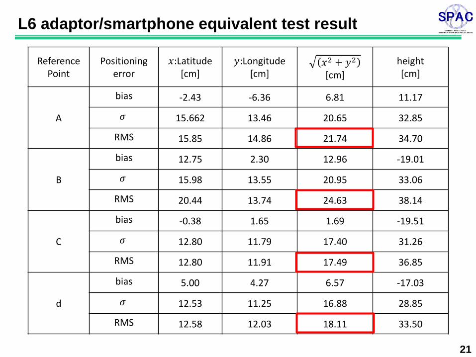
21
Reference
Point Positioning
error 𝑥:Latitude
[cm] 𝑦:Longitude
[cm] 𝑥2 + 𝑦2 [cm]
height [cm]
A
bias -2.43 -6.36 6.81 11.17
𝜎 15.662 13.46 20.65 32.85
RMS 15.85 14.86 21.74 34.70
B
bias 12.75 2.30 12.96 -19.01
𝜎 15.98 13.55 20.95 33.06
RMS 20.44 13.74 24.63 38.14
C
bias -0.38 1.65 1.69 -19.51
𝜎 12.80 11.79 17.40 31.26
RMS 12.80 11.91 17.49 36.85
d
bias 5.00 4.27 6.57 -17.03
𝜎 12.53 11.25 16.88 28.85
RMS 12.58 12.03 18.11 33.50
L6 adaptor/smartphone equivalent test result
22
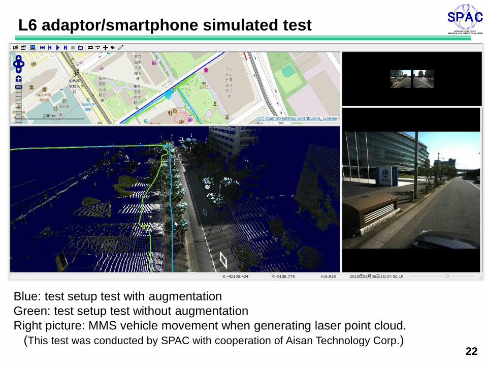
L6 adaptor/smartphone simulated test
Blue: test setup test with augmentation
Green: test setup test without augmentation
Right picture: MMS vehicle movement when generating laser point cloud.
(This test was conducted by SPAC with cooperation of Aisan Technology Corp.)
23
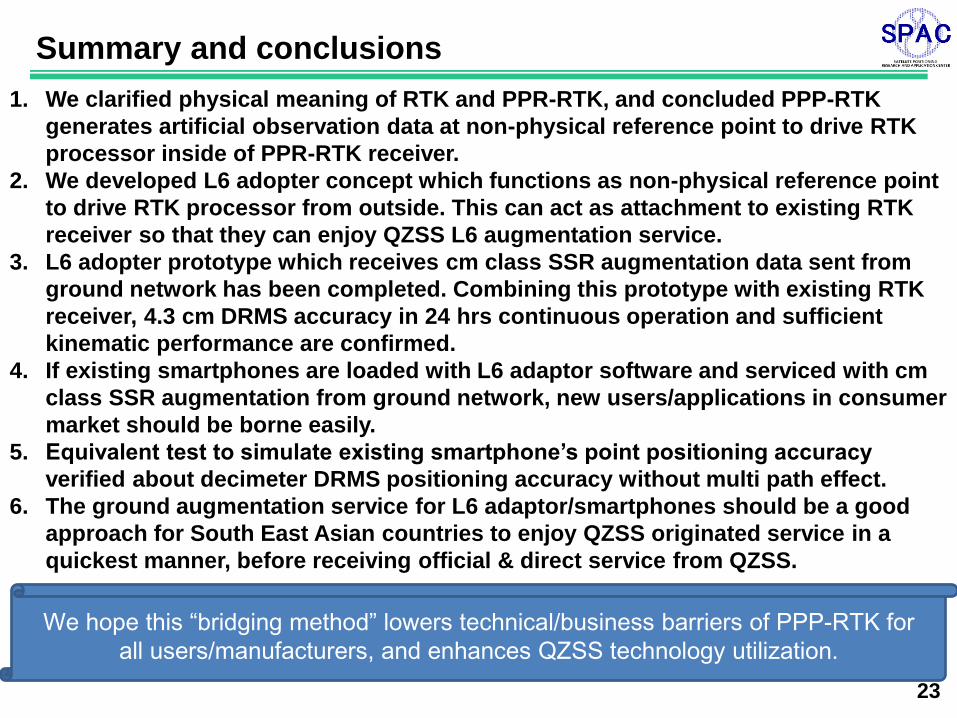
Summary and conclusions
1. We clarified physical meaning of RTK and PPR-RTK, and concluded PPP-RTK
generates artificial observation data at non-physical reference point to drive RTK
processor inside of PPR-RTK receiver.
2. We developed L6 adopter concept which functions as non-physical reference point
to drive RTK processor from outside. This can act as attachment to existing RTK
receiver so that they can enjoy QZSS L6 augmentation service.
3. L6 adopter prototype which receives cm class SSR augmentation data sent from
ground network has been completed. Combining this prototype with existing RTK
receiver, 4.3 cm DRMS accuracy in 24 hrs continuous operation and sufficient
kinematic performance are confirmed.
4. If existing smartphones are loaded with L6 adaptor software and serviced with cm
class SSR augmentation from ground network, new users/applications in consumer
market should be borne easily.
5. Equivalent test to simulate existing smartphone’s point positioning accuracy
verified about decimeter DRMS positioning accuracy without multi path effect.
6. The ground augmentation service for L6 adaptor/smartphones should be a good
approach for South East Asian countries to enjoy QZSS originated service in a
quickest manner, before receiving official & direct service from QZSS.
We hope this “bridging method” lowers technical/business barriers of PPP-RTK for
all users/manufacturers, and enhances QZSS technology utilization.
24
If any questions and inquiry, please visit
Soartech system booth
at exhibition hall,
or send E mail to
Dr. Izumi Mikami
Thank you for your
kind attention!