Embed Size (px)
Citation preview
TYPICAL INJECTION SYSTEM AND SILO DESIGN FOR
AMENDED SILICATES
Provided By
NOVINDA CORPORATION 999 18TH Street
Suite 1755, North Tower Denver, CO 80202
October 2013
DISCLAIMER:
The information provided within these documents has been provided by Novinda and its representatives, and is to be used for general
background informational purposes only. The information regarding the use, application, storage, or delivery of Novinda’s amended silicates
mercury sorbent material is conceptual only, and has not been demonstrated in full scale application. Novinda is unable to report on or
accurately predict events that may affect full scale application. Novinda and its representatives provide no warranty of any kind, implied or
expressed, regarding the accuracy or suitability of this information. As such, the Receiving Party acknowledges and agrees that Novinda and its
representatives will under no circumstances be liable for any damage or loss however incurred from this information.
Rev. 10/09/13 Page 1 of 9
AMENDED SILICATES INJECTION SYSTEM
Table of Contents
1. General Description 2. Scope of Work 3. Material Properties & Injection Rates 4. Technical Requirements 5. Performance Requirements 6. Typical Silo Design for Amended Silicates and Powdered Activated Carbon
Appendix A – Schematic Flow Diagram – Novinda Amended Silicates
Appendix B – MSDS Sheets – Novinda Amended Silicates
Appendix C – Instructions to Bidders
Appendix D – Terms and Conditions – Provided by Owner
Appendix E – Facility Details – Provided by Owner
Appendix F – Lance Details
Appendix G – Jenike & Johanson Typical Silo Design for Amended Silicates and Powdered Activated Carbon
Rev. 10/09/13 Page 2 of 9
AMENDED SILICATES INJECTION SYSTEM
1. General Description
This specification covers the overall description, work scope, technical and performance requirements of a reagent injection system for a mercury emission control project. The specification requirements listed herein are based primarily on the work by Jenike & Johanson for Novinda and represent the minimum requirements to achieve consistent flow of the amended silicates material, and Novinda retains the right to review Owner’s design and drawings prior to fabrication and installation of the injection system. Designs deviating from these specifications may be considered on a case by case basis.
2. Scope of Work
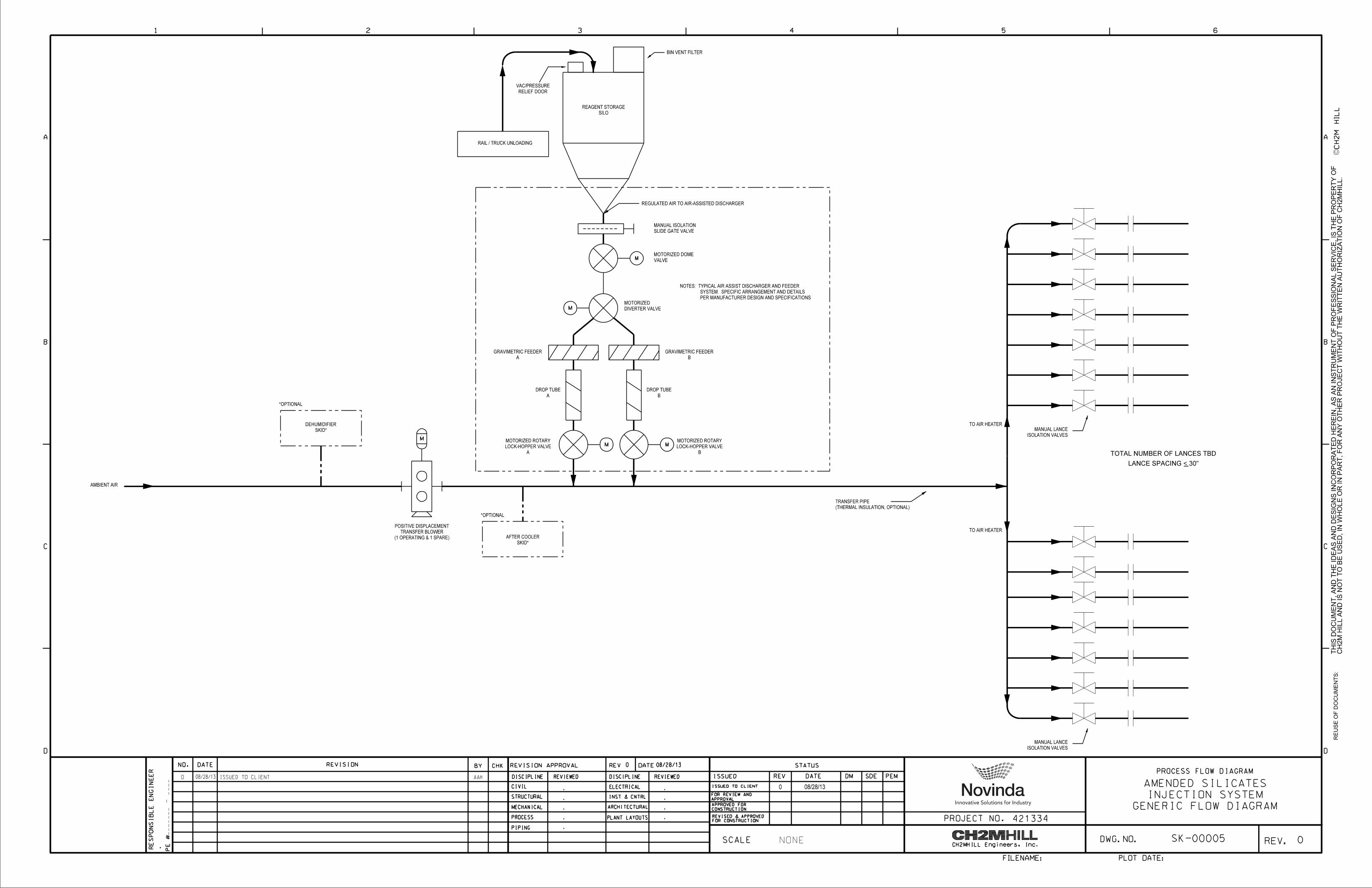
The scope of work is to design, engineer, procure, fabricate and deliver the specified reagent injection system, support start up and testing of a complete, fully functional and operational mercury emission control system, which includes at a minimum but not limited to the items and services listed below. A typical schematic flow diagram of the injection system with termination points for the scope of work is shown in Appendix A.
1. Reagent Injection System including transfer blowers, material metering and feeding equipment and all required manual and motorized valves.
2. Reagent storage silo with vacuum/pressure relief door, bin vent fabric filter & vent fan and transfer pipe suitable to receive and transfer material from either rail cars or delivery trucks.
3. Transfer pipes from blower discharge to lance inlets including manual isolation valve at each. 4. All auxiliary electric system and controls for above scope.
3. Material Properties
The injection system shall be capable of unloading, handling, feeding, and injecting multiple sorbent materials, including amended silicates and powdered activated carbon (PAC). Detailed material properties and injection equipment design criteria for amended silicates are provided by Jenike & Johanson (J&J) and are listed within this specification section. Equipment design and operational considerations for the explosive and flammable properties of any sorbent material is the responsibility of the Owner and Bidder. Bidder shall also be responsible for ensuring that other PAC materials can be also utilized by the injection system. The injection system silo shall be designed to allow mass flow instead of funnel flow. A mass flow silo allows for first-in-first-out material flow, eliminates ratholes and stagnant material, and minimizes material segregation effects. The following criterion represents typical limiting conditions for flow, therefore larger silo outlets, steeper hoppers, and flow rates summarized below are acceptable: Cohesive Strength Since sorbent materials are cohesive and have the capacity to form a rathole in the injection system storage silo, the following are minimum mass flow silo discharge outlet diameter dimensions for gravity feed (GF) and air assisted silo bin bottoms. Continuous flow (GF) 1.3 feet After 1 day at rest (GF) 2.1 feet
Rev. 10/09/13 Page 3 of 9
For air assisted silo bin bottom 0.5 feet Compressibility Bulk density shall be considered in the design for silo loads, silo capacities, and system feed density. The range of bulk density for the amended silicates material is as follows: Measured range of bulk density 32.2 to 58.5 pounds per cubic foot PAC assumed bulk density 30 pounds per cubic foot Mass Flow Hopper Angles Design of the mass flow silo hopper shall include hopper angle, materials of construction, and surface finish. Hopper material shall have interior sloping surfaces lined with 304 stainless steel and #2B finish (cold rolled mill finish which cannot be achieved by polishing). Maximum recommended mass flow wall angles 10 degrees (from vertical for both continuous flow and after 1 day storage at rest) The MSDS for the amended silicates material can be found in Appendix B.
4. Technical Requirements
4.1 General
4.1.1 Engineering
The Contractor shall be responsible for performing all engineering and design, necessary for a complete and operating facility designated to be within Contractor’s scope, as spelled out herein. All project documents shall be signed and sealed by an engineer or architect registered in the state where the installation shall be located.
4.1.2 Procurement
The Contractor shall be responsible for the procurement of all permanent materials and engineered equipment necessary for a complete and operating facility designated to be within Contractor’s scope, including freight to the site, unloading and/or safe storage,
unless materials are specifically spelled out as “Owner-provided” within this document.
4.2 Mechanical
4.2.1 Equipment
Major pieces of equipment, include but not limited to, are listed in the following table.
Table1. Equipment List
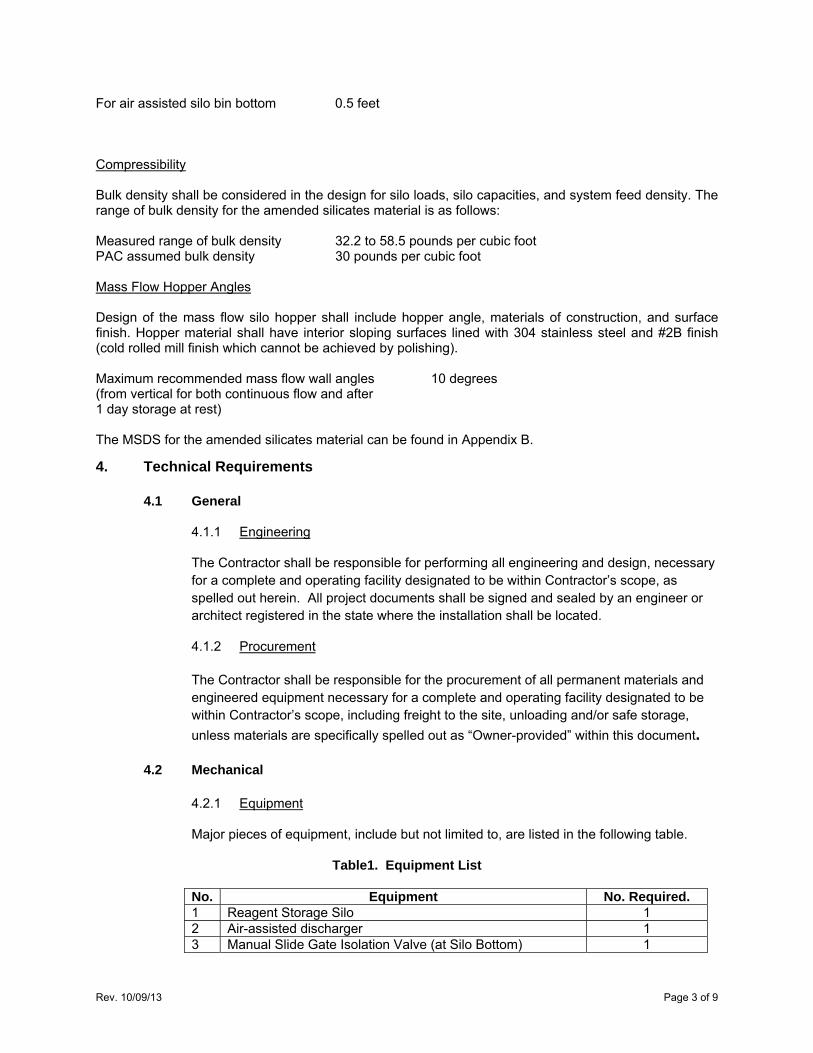
No. Equipment No. Required. 1 Reagent Storage Silo 1 2 Air-assisted discharger 1 3 Manual Slide Gate Isolation Valve (at Silo Bottom) 1
Rev. 10/09/13 Page 4 of 9
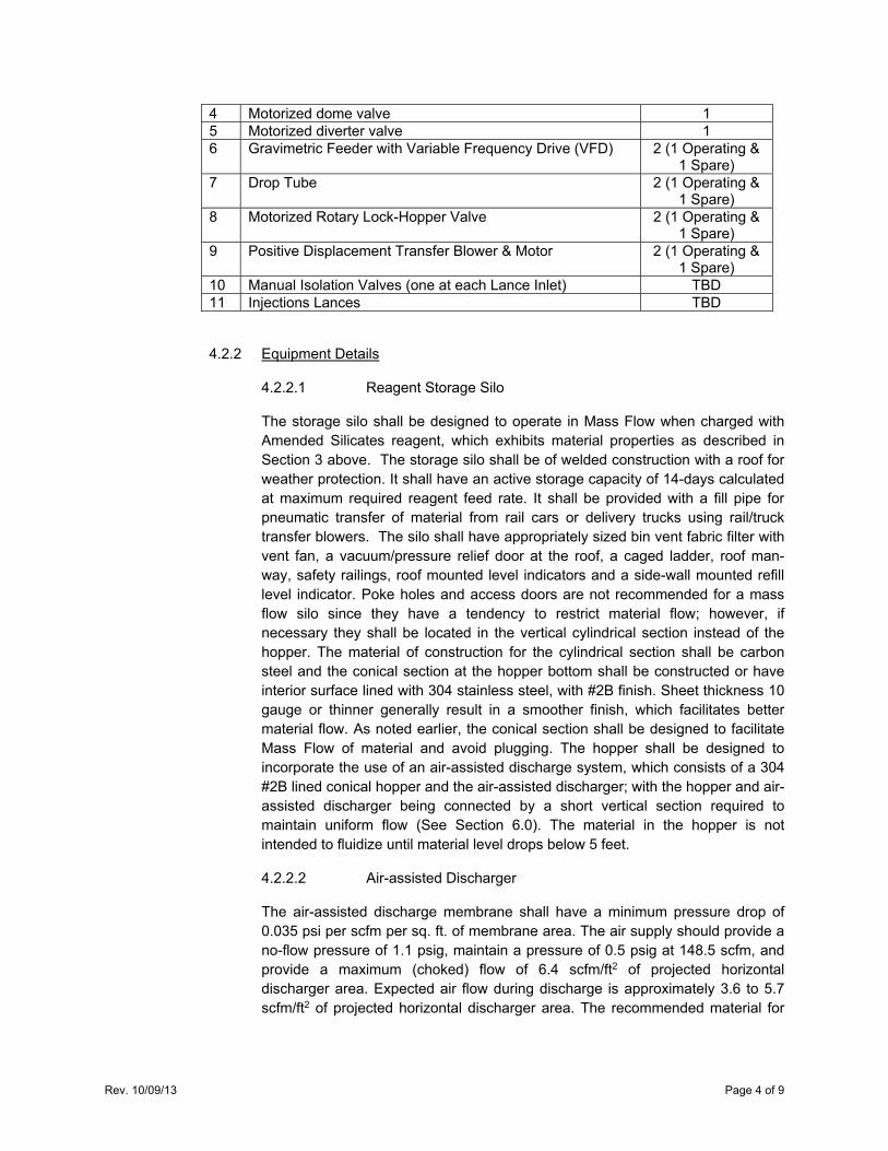
4 Motorized dome valve 1 5 Motorized diverter valve 1 6 Gravimetric Feeder with Variable Frequency Drive (VFD) 2 (1 Operating &
1 Spare) 7 Drop Tube 2 (1 Operating &
1 Spare) 8 Motorized Rotary Lock-Hopper Valve 2 (1 Operating &
1 Spare) 9 Positive Displacement Transfer Blower & Motor 2 (1 Operating &
1 Spare) 10 Manual Isolation Valves (one at each Lance Inlet) TBD 11 Injections Lances TBD
4.2.2 Equipment Details
4.2.2.1 Reagent Storage Silo
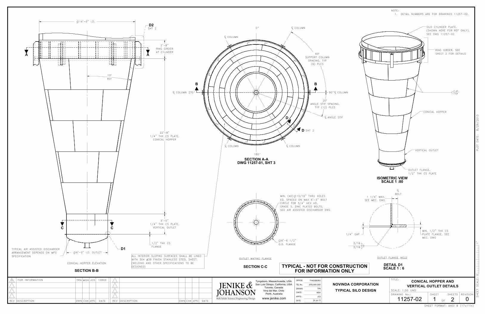
The storage silo shall be designed to operate in Mass Flow when charged with Amended Silicates reagent, which exhibits material properties as described in Section 3 above. The storage silo shall be of welded construction with a roof for weather protection. It shall have an active storage capacity of 14-days calculated at maximum required reagent feed rate. It shall be provided with a fill pipe for pneumatic transfer of material from rail cars or delivery trucks using rail/truck transfer blowers. The silo shall have appropriately sized bin vent fabric filter with vent fan, a vacuum/pressure relief door at the roof, a caged ladder, roof man-way, safety railings, roof mounted level indicators and a side-wall mounted refill level indicator. Poke holes and access doors are not recommended for a mass flow silo since they have a tendency to restrict material flow; however, if necessary they shall be located in the vertical cylindrical section instead of the hopper. The material of construction for the cylindrical section shall be carbon steel and the conical section at the hopper bottom shall be constructed or have interior surface lined with 304 stainless steel, with #2B finish. Sheet thickness 10 gauge or thinner generally result in a smoother finish, which facilitates better material flow. As noted earlier, the conical section shall be designed to facilitate Mass Flow of material and avoid plugging. The hopper shall be designed to incorporate the use of an air-assisted discharge system, which consists of a 304 #2B lined conical hopper and the air-assisted discharger; with the hopper and air-assisted discharger being connected by a short vertical section required to maintain uniform flow (See Section 6.0). The material in the hopper is not intended to fluidize until material level drops below 5 feet.
4.2.2.2 Air-assisted Discharger
The air-assisted discharge membrane shall have a minimum pressure drop of 0.035 psi per scfm per sq. ft. of membrane area. The air supply should provide a no-flow pressure of 1.1 psig, maintain a pressure of 0.5 psig at 148.5 scfm, and provide a maximum (choked) flow of 6.4 scfm/ft2 of projected horizontal discharger area. Expected air flow during discharge is approximately 3.6 to 5.7 scfm/ft2 of projected horizontal discharger area. The recommended material for
Rev. 10/09/13 Page 5 of 9
the membrane is Polyveyor 1950 which is available from BeltService Corporation, or J&J approved equal.
The air-assisted discharger shall be a standard 6 foot diameter unit with minimum 6 inch outlet, and be supplied by Premier Pneumatics, Kice Industries, Nol-Tec Systems, Young Industries, Clyde Bergemann, or J&J approved equal. Compressed air that is introduced to the silo and that can come in contact with the silo contents shall be dried to a maximum dew point of -40◦F. The compressed air supply to the air-assisted discharger shall be provided by a pilot operated low-pressure regulator, such as a Fisher-Rosemont 299 series, or J&J approved equal. A pressure gauge shall be connected to the membrane plenum to serve as an indicator of a plugged or damaged membrane. Alternative air supply methods include regenerative blowers, or lobed-type blowers if supplied with controls to maintain constant pressure output over the required range of flow rates. Regardless of air supply equipment, an overpressure protection device shall be installed to the membrane plenum for safety. As an additional safety precaution, the silo shall be vented and an overpressure protection device utilized to allow for air flow into the silo.
4.2.2.3 Manual Isolation Valve at Silo Bottom
Bidder’s standard design proven in similar applications is acceptable.
4.2.2.4 Motorized Dome Valve
The outlet valve shall be high duty cycle dome type valve, supplied by Gemco, RoValve, Clyde Industries, or J&J approved equal. The outlet valve shall be fully open or fully closed, and shall not be operated partially open to throttle flow.
4.2.2.5 Automated Diverter Valve
The outlet stream can be directed to multiple fill points with the use of 12 inch air slides and diverter valves. Bidder’s standard design proven in similar applications is acceptable.
4.2.2.6 Gravimetric Feeder
The gravimetric feeder shall be capable of supplying 10-500 lb/hr as delivered with the capability to change the feed rate range by changing out the feed screw and delivery tube. The gravimetric feeder screw shall be controlled by a Variable Frequency Drive (VFD) that provides finite local adjustment of the reagent feed rate. The feeder shall be accurate within + / - 1% or 1 lb/hr (whichever is more) over a one minute interval. Modulation of material flow shall be accomplished by the feeder and not by a valve.
4.2.2.7 Drop Tube
The drop tube connected downstream of the gravimetric feeder outlet and upstream of the motorized rotary lock-hopper valve inlet shall be equipped with an inlet air filter that shall also provide a barrier against material exiting the top of the drop tube.
Rev. 10/09/13 Page 6 of 9
4.2.2.8 Motorized Rotary Lock-Hopper Valves
The rotary lock hopper valve shall be designed to convey a fine powder of the quantity specified in the Section 3 above and the distance of the Transfer Pipe System. Valve body/cylinder clearances shall be a ‘close-tolerance’ design.
4.2.2.9 Positive Displacement Transfer Blowers
Two positive displacement transfer blowers (one operating and one in-line spare) capable of meeting the feed rates listed in the Facility Details found in Appendix E and conveying the distance of the Transfer Pipe System (distance to be determined by Contractor and Owner). Blowers shall be sized to maintain Industry-practice velocities in all transfer lines and lances. The blowers shall be equipped with an inlet filter/silencer and all appurtenances necessary for safe start-up, operation & maintenance, and shut-down.
4.2.2.10 Manual Lance Isolation Valve
Bidder’s standard design proven in similar applications is acceptable.
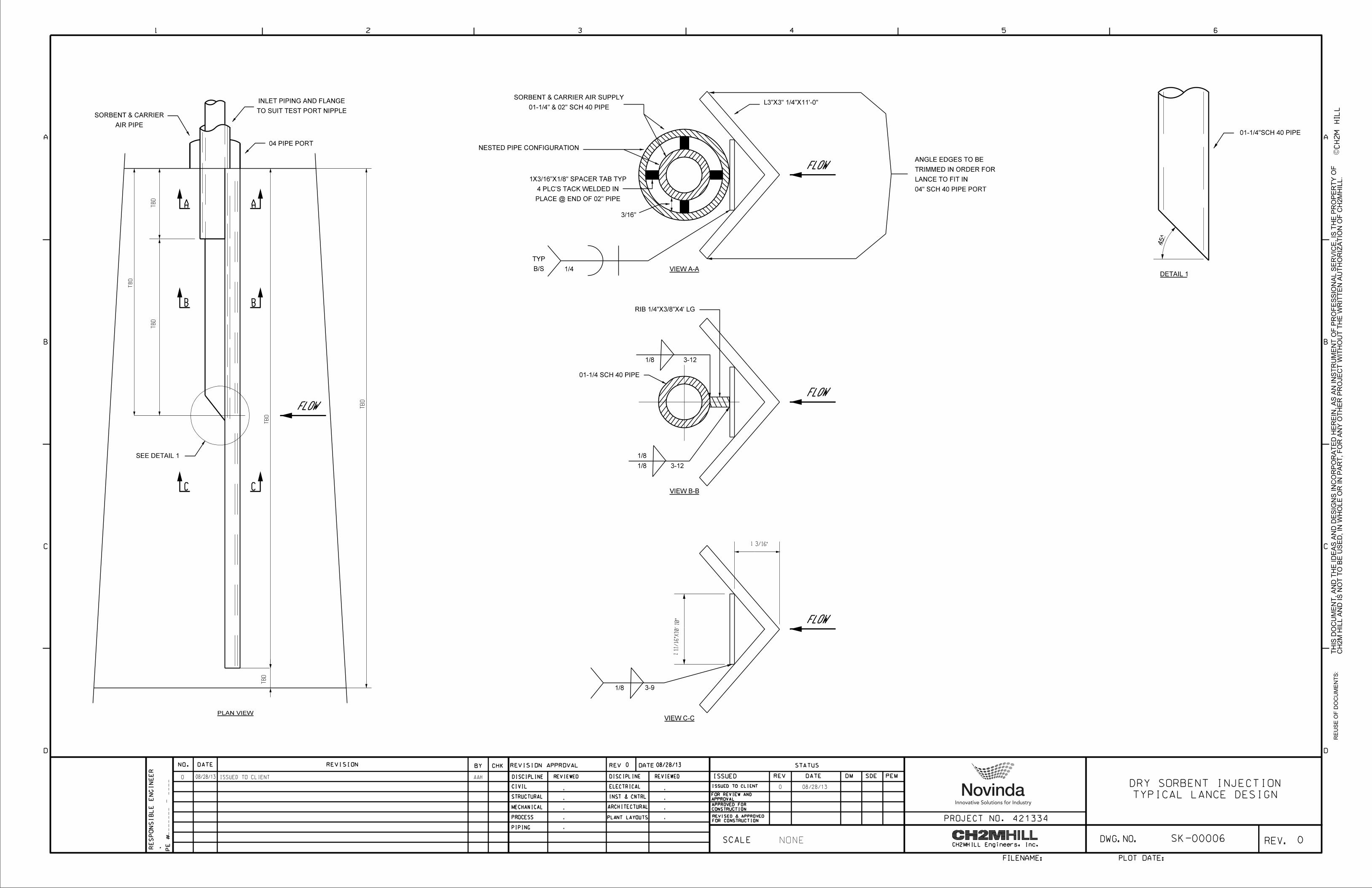
4.2.2.11 Injection Lances
The lance shall use a concentric tube design that incorporates a flat or angled baffle affixed to the upstream side of the lance, normal to the bulk flow of the flue gas. The concentric tubes shall terminate at various distances across the duct to promote uniform distribution of reagent downstream of the baffle plate. The baffle plate induces local turbulence near the lance discharge points and promotes distribution along the axis of the lance. A sketch showing lance details is included in Appendix F. The number and location of the injection lances are to be determined by Contractor and Owner; however, lance spacing shall not be greater than 30 inches.
4.2.3 Equipment O&M Manual
Contractor shall provide the operations and maintenance (O&M) manuals for the scope of work. The O&M manuals shall consist of hard-copy binders and CDs with operations and maintenance data and information for the scope of work.
4.3 Piping
4.3.1 Feed Pipe System
The feed pipe system connects the storage silo outlet, manual isolation slide gate valve, motorized dome valve, motorized diverter valve, gravimetric feeder, drop tube, and motorized rotary lock-hopper valve to the transfer pipe system. Equipment within the feed pipe system is arranged as shown in Appendix A, and shall be close-coupled so as to minimize the length of feed pipe required; no elbows are allowed. The feed pipe shall be Schedule 80 carbon steel.
A spare feed pipe system consisting of the gravimetric feeder, drop tube, and motorized rotary lock-hopper valve shall be installed for redundancy to allow for scheduled and unscheduled maintenance activities. The automated diverter valve will be used to select
Rev. 10/09/13 Page 7 of 9
the feed pipe system. In all locations that include two phase flow, i.e. transport air + solids, minimum acceptable gas velocity must be maintained in order to avoid saltation of the larger particles present in the solid material.
4.3.2 Transfer Pipe System
The transfer pipe system consists of transfer pipes from the discharges of the transfer blower and motorized rotary lock-hopper valve to the lances, inclusive. The downstream side of the lance isolation valves shall be flanged connections. The injection lances shall bolt up to these isolation valve flanged connections. The transfer pipe shall be Schedule 80 carbon steel, with a minimum of 2” bidder’s standard thermal insulation with cladding proven in similar applications. Long radius elbows shall be used to mitigate erosion and the elbows and tee sections shall have replaceable wear plates to facilitate maintenance. The system shall be designed with transport velocities that prevent settling in the pipes at all load conditions and shall accommodate a nominal flow of 35 scfm per lance. The conveying distance shall be specific to each site/installation. The Contractor shall work with the facility Owner to identify the optimum Transfer Pipe routing. The transfer pipe shall be routed to the lance locations, which shall be uniquely identified for each unit; however lance spacing shall not be greater than 30 inches. The transfer pipe system lay out shall consider flow balance to injection lances, access for existing plant equipment in the area for maintenance, and minimal interference with plant operation during construction.
4.4 Electrical
4.4.1 Power Supply
Contractor is to provide a single 480 V, 3 Phase, 60 Hz power supply to supply all of the necessary electrical functions of the system.
4.4.2 Power Distribution
A main disconnect breaker shall be provided in the control panel, which shall be utilized to protect and to de-energize all reagent injection system equipment. A motor circuit protector, a starter and overload protection shall be provided for the 480-volt transfer blower motor. Three phase breakers shall be provided for power distribution to the control power transformer.
4.4.3 Control Panel
The reagent injection system controls and power distribution shall be contained within a dedicated control panel(s), including Programmable Logic Controller (PLC), Human Machine Interface (HMI), power supply, control relays, lights, terminal blocks, motor circuit protectors, motor starters, circuit breakers, etc. The control panel(s) shall be mounted in a conveniently accessible location. Panels shall be rated NEMA 4X. Terminal blocks shall be installed for termination of all District installed cables. All devices that shall be visible on the front of the control panels shall have durable, tight- adhering nameplates. Wiring shall be stranded copper, 600 volt, insulated, extra flexible type. As a minimum, wire size shall be #12 American Wire Gauge (AWG) for all power wiring, #14 AWG for all control panel exterior control wiring, #16 for all control panel interior control wiring and #18 AWG twisted shielded pair for analog signal conductors.
Rev. 10/09/13 Page 8 of 9
4.5 Instrumentation and Control
The system shall have the capability to set the maximum feed rate locally and adjust the feed rate from zero to the maximum user defined feed rate via an external 4-20mA signal. The system shall be capable of storing and exporting time stamped operating data which shall include the system feed rate as measured by the gravimetric feeder. The system shall be capable of storing at least one week’s worth (seven x twenty-four hour days) of such data taken at one (1) minute intervals. The data must be formatted such that it can easily be imported to a PC and Windows Excel.
4.5.1 PLC
The PLC shall control all necessary system functions such as startup, shutdown, feed rate control, feed piping selection (via diverter valve position), alarm functions and trips.
4.5.2 HMI
All local control and alarm monitoring shall be provided through a local HMI. The HMI shall have sufficient screens to display the following controls as a minimum:
1. System Control
2. Feeder Control
3. Status Display
4. Fluidizing Control
5. Transfer Blower Control
6. Feed Rate Set Point
7. Feed Piping Selection (A/B Train)
8. Active Alarms
a. The following status and alarms shall be displayed on the HMI:
i. Transfer Blower Status ON/OFF
ii. Gravimetric Feeder Status (A & B trains) ON/OFF
iii. Reagent Storage Silo Level Status LOW
iv. Gravimetric Feeder Status (A & B trains) MALFUNCTION
v. Transfer Blower Discharge Pressure HIGH/LOW
vi. Rotary Lock Hopper Valve Inlet Pressure (A & B trains) HIGH/LOW
b. The following control functions shall be on the HMI:
i. Local Start Selection Key
ii. Local Stop Selection Key
iii. Gravimetric Feeder OFF/AUTO Selection Keys (A & B trains)
iv. Alarm Acknowledge Selection Key
v. System Operation Local/Remote Selection Key
vi. System Mode Non-Paced/Paced Selection Key
vii. Fluidization System HAND/OFF/AUTO Selection Key
c. The following control switches shall be located on the control panel:
Rev. 10/09/13 Page 9 of 9
i. System Stop Pushbutton Switch / Emergency Stop
4.5.3 Gravimetric Feeder Speed Controllers
Each gravimetric feeder screw shall be controlled by a Variable Frequency Drive (VFD) providing finite local adjustment of the reagent feeding rate. Based on the system operating mode selected, the controller shall follow a constant feed rate or an analog 4-20 mA signal provided by an external source.
4.5.4 Sensors and Trips
The following system sensors and trips shall be provided at a minimum:
1. Transfer Blower Outlet Pressure Sensor
2. Rotary Lock Hopper Valve Inlet Pressure Sensor (A & B trains)
3. Drop Tube pressure differential (A & B trains) - if this approaches zero, the trip shall at a minimum shutdown the Gravimetric Feeder.
4. Gravimetric Feeder Hopper Low level Switch (A & B trains)
5. Gravimetric Feeder Hopper High Level Switch (A & B trains)
5. Performance Requirements
The Performance Requirements shall include but not limited to:
The system shall be capable of delivering the maximum and the minimum reagent feed rates specified.
The reagent distribution between the lances shall be uniform at all injection rates, i.e., the reagent flow at each lance shall be the same
Noise level shall not exceed 85 dBA at 3 ft. from the blower and all rotary/other equipment.
6. Typical Silo Design for Amended Silicates and Powdered Activated Carbon
The J&J silo design drawings in Appendix G provide an example of a typical amended silicates mass flow silo. The design and other details are provided for information only and to facilitate the Bidder in designing a silo suitable for this application. Each injection system and silo shall be designed for specific facility site conditions, duty, and performance requirements. Alternative designs may be considered at the discretion of the Owner.
Rev. 10/09/13
APPENDIX A
Schematic Flow Diagram
Novinda Amended Silicates
08/28/13
_______ - ____
.
.
.
.
.
.
.
.
.
.
AAH08/28/13
NONE
SILO
REAGENT STORAGE
SLIDE GATE VALVE
MANUAL ISOLATION
*OPTIONAL
AMBIENT AIR
*OPTIONAL
SKID*
AFTER COOLER
BIN VENT FILTER
RELIEF DOOR
VAC/PRESSURE
M
M
ISOLATION VALVES
MANUAL LANCE
PROCESS FLOW DIAGRAM
INJECTION SYSTEM
SK-00005
ISOLATION VALVES
MANUAL LANCE
M
(1 OPERATING & 1 SPARE)
TRANSFER BLOWER
POSITIVE DISPLACEMENT
TO AIR HEATER
TO AIR HEATER
(THERMAL INSULATION, OPTIONAL)
TRANSFER PIPE
GENERIC FLOW DIAGRAM
AMENDED SILICATES
RAIL / TRUCK UNLOADING
SKID*
DEHUMIDIFIER
LANCE SPACING < 30"
TOTAL NUMBER OF LANCES TBD
REGULATED AIR TO AIR-ASSISTED DISCHARGER
M
VALVE
MOTORIZED DOME
DIVERTER VALVE
MOTORIZED
A
GRAVIMETRIC FEEDER
B
GRAVIMETRIC FEEDER
A
DROP TUBE
B
DROP TUBE
A
LOCK-HOPPER VALVE
MOTORIZED ROTARY
B
LOCK-HOPPER VALVE
MOTORIZED ROTARY
ISSUED TO CLIENT0
0
0
PER MANUFACTURER DESIGN AND SPECIFICATIONS
SYSTEM. SPECIFIC ARRANGEMENT AND DETAILS
NOTES: TYPICAL AIR ASSIST DISCHARGER AND FEEDER
M
08/28/130
THIS D
OC
UM
EN
T,
AN
D T
HE I
DE
AS A
ND D
ESIG
NS I
NC
OR
PO
RA
TE
D H
ER
EIN,
AS A
N I
NS
TR
UM
EN
T O
F P
RO
FE
SSIO
NA
L S
ER
VIC
E, IS T
HE P
RO
PE
RT
Y O
FC
H2
M HIL
L A
ND IS N
OT T
O B
E U
SE
D, IN W
HO
LE O
R I
N P
AR
T, F
OR A
NY O
TH
ER P
ROJE
CT W
ITH
OU
T T
HE W
RIT
TE
N A
UT
HO
RIZ
ATIO
N O
F C
H2
MHIL
L.
RE
US
E O
F D
OC
UM
EN
TS:
C
A
B
C
D
NO. REVISIONDATE
c
D
A
B
654321
CH2
M
HIL
L
FILENAME: PLOT DATE:
REV
DISCIPLINE
CIVIL
STRUCTURAL
MECHANICAL
PROCESS
DISCIPLINE
PIPING
ELECTRICAL
REVIEWED REVIEWED
REVISION APPROVAL DATE
REV.
PE #
SCALE
DATE
STATUS
FOR CONSTRUCTION
REVISED & APPROVED
CONSTRUCTION
APPROVED FOR
ISSUED REV SDE PEM
RE
SP
ON
SI
BL
E
EN
GI
NE
ER
DM
BY CHK
INST & CNTRL
PROJECT NO.
DWG. NO.
421334PLANT LAYOUTS
ARCHITECTURAL
CH2MHILL Engineers, Inc.
ISSUED TO CLIENT
APPROVAL
FOR REVIEW AND
Rev. 10/09/13
APPENDIX B
MSDS Sheets – Amended Silicates
MATERIAL SAFETY DATA SHEET
1. Product and Company Identification
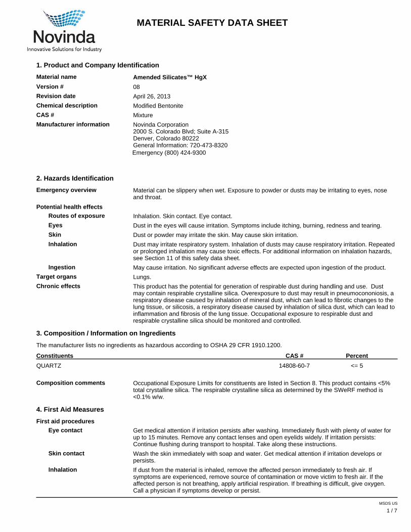
Material name Amended Silicates™ HgX
Version # 08
Revision date April 26, 2013
Chemical description Modified Bentonite
CAS # Mixture
Manufacturer information Novinda Corporation2000 S. Colorado Blvd; Suite A-315Denver, Colorado 80222General Information: 720-473-8320Emergency (800) 424-9300
2. Hazards Identification
Emergency overview Material can be slippery when wet. Exposure to powder or dusts may be irritating to eyes, noseand throat.
Potential health effects
Routes of exposure Inhalation. Skin contact. Eye contact.
Eyes Dust in the eyes will cause irritation. Symptoms include itching, burning, redness and tearing.
Skin Dust or powder may irritate the skin. May cause skin irritation.
Inhalation Dust may irritate respiratory system. Inhalation of dusts may cause respiratory irritation. Repeatedor prolonged inhalation may cause toxic effects. For additional information on inhalation hazards,see Section 11 of this safety data sheet.
Ingestion May cause irritation. No significant adverse effects are expected upon ingestion of the product.
Target organs Lungs.
Chronic effects This product has the potential for generation of respirable dust during handling and use. Dustmay contain respirable crystalline silica. Overexposure to dust may result in pneumocononiosis, arespiratory disease caused by inhalation of mineral dust, which can lead to fibrotic changes to thelung tissue, or silicosis, a respiratory disease caused by inhalation of silica dust, which can lead toinflammation and fibrosis of the lung tissue. Occupational exposure to respirable dust andrespirable crystalline silica should be monitored and controlled.
3. Composition / Information on Ingredients
The manufacturer lists no ingredients as hazardous according to OSHA 29 CFR 1910.1200.
Constituents CAS # Percent
QUARTZ 14808-60-7 <= 5
Composition comments Occupational Exposure Limits for constituents are listed in Section 8. This product contains <5%total crystalline silica. The respirable crystalline silica as determined by the SWeRF method is<0.1% w/w.
4. First Aid Measures
First aid procedures
Eye contact Get medical attention if irritation persists after washing. Immediately flush with plenty of water forup to 15 minutes. Remove any contact lenses and open eyelids widely. If irritation persists:Continue flushing during transport to hospital. Take along these instructions.
Skin contact Wash the skin immediately with soap and water. Get medical attention if irritation develops orpersists.
Inhalation If dust from the material is inhaled, remove the affected person immediately to fresh air. Ifsymptoms are experienced, remove source of contamination or move victim to fresh air. If theaffected person is not breathing, apply artificial respiration. If breathing is difficult, give oxygen.Call a physician if symptoms develop or persist.
MSDS US
1 / 7
Material Name: AS HgX Version #8; April 26, 2013
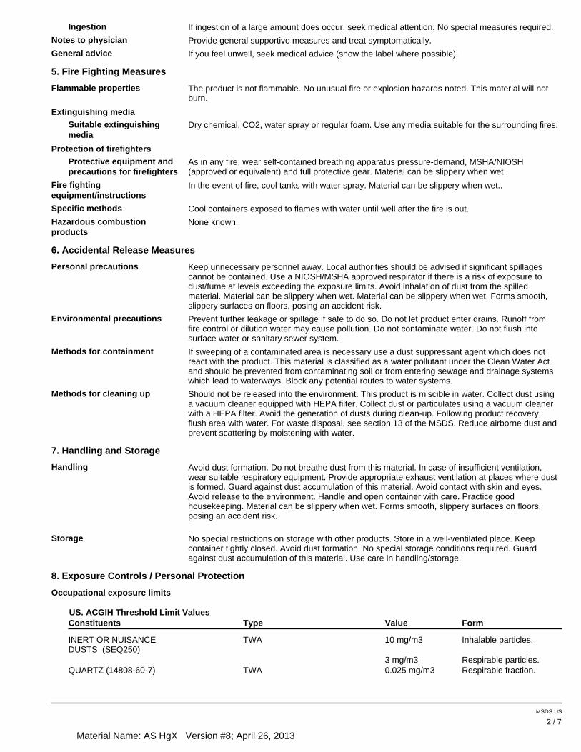
Ingestion If ingestion of a large amount does occur, seek medical attention. No special measures required.
Notes to physician Provide general supportive measures and treat symptomatically.
General advice If you feel unwell, seek medical advice (show the label where possible).
5. Fire Fighting Measures
Flammable properties The product is not flammable. No unusual fire or explosion hazards noted. This material will notburn.
Extinguishing media
Suitable extinguishing media
Dry chemical, CO2, water spray or regular foam. Use any media suitable for the surrounding fires.
Protection of firefighters
Protective equipment andprecautions for firefighters
As in any fire, wear self-contained breathing apparatus pressure-demand, MSHA/NIOSH(approved or equivalent) and full protective gear. Material can be slippery when wet.
Fire fighting equipment/instructions
In the event of fire, cool tanks with water spray. Material can be slippery when wet..
Specific methods Cool containers exposed to flames with water until well after the fire is out.
Hazardous combustionproducts
None known.
6. Accidental Release Measures
Personal precautions Keep unnecessary personnel away. Local authorities should be advised if significant spillagescannot be contained. Use a NIOSH/MSHA approved respirator if there is a risk of exposure todust/fume at levels exceeding the exposure limits. Avoid inhalation of dust from the spilledmaterial. Material can be slippery when wet. Material can be slippery when wet. Forms smooth,slippery surfaces on floors, posing an accident risk.
Environmental precautions Prevent further leakage or spillage if safe to do so. Do not let product enter drains. Runoff fromfire control or dilution water may cause pollution. Do not contaminate water. Do not flush intosurface water or sanitary sewer system.
Methods for containment If sweeping of a contaminated area is necessary use a dust suppressant agent which does notreact with the product. This material is classified as a water pollutant under the Clean Water Actand should be prevented from contaminating soil or from entering sewage and drainage systemswhich lead to waterways. Block any potential routes to water systems.
Methods for cleaning up Should not be released into the environment. This product is miscible in water. Collect dust usinga vacuum cleaner equipped with HEPA filter. Collect dust or particulates using a vacuum cleanerwith a HEPA filter. Avoid the generation of dusts during clean-up. Following product recovery,flush area with water. For waste disposal, see section 13 of the MSDS. Reduce airborne dust andprevent scattering by moistening with water.
7. Handling and Storage
Handling Avoid dust formation. Do not breathe dust from this material. In case of insufficient ventilation,wear suitable respiratory equipment. Provide appropriate exhaust ventilation at places where dustis formed. Guard against dust accumulation of this material. Avoid contact with skin and eyes.Avoid release to the environment. Handle and open container with care. Practice goodhousekeeping. Material can be slippery when wet. Forms smooth, slippery surfaces on floors,posing an accident risk.
Storage No special restrictions on storage with other products. Store in a well-ventilated place. Keepcontainer tightly closed. Avoid dust formation. No special storage conditions required. Guardagainst dust accumulation of this material. Use care in handling/storage.
8. Exposure Controls / Personal Protection
Occupational exposure limits
US. ACGIH Threshold Limit ValuesFormValue TypeConstituents
INERT OR NUISANCEDUSTS (SEQ250)
TWA 10 mg/m3 Inhalable particles.
3 mg/m3 Respirable particles.QUARTZ (14808-60-7) TWA 0.025 mg/m3 Respirable fraction.
MSDS US
2 / 7
Material Name: AS HgX Version #8; April 26, 2013
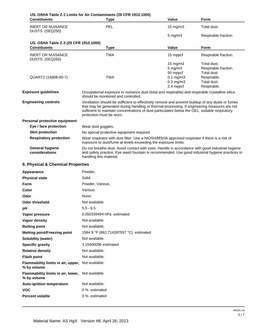
US. OSHA Table Z-1 Limits for Air Contaminants (29 CFR 1910.1000)FormValue TypeConstituents
INERT OR NUISANCEDUSTS (SEQ250)
PEL 15 mg/m3 Total dust.
5 mg/m3 Respirable fraction.
US. OSHA Table Z-3 (29 CFR 1910.1000)FormValue TypeConstituents
INERT OR NUISANCEDUSTS (SEQ250)
TWA 15 mppcf Respirable fraction.
15 mg/m3 Total dust.5 mg/m3 Respirable fraction.50 mppcf Total dust.
QUARTZ (14808-60-7) TWA 0.1 mg/m3 Respirable.0.3 mg/m3 Total dust.2.4 mppcf Respirable.
Exposure guidelines Occupational exposure to nuisance dust (total and respirable) and respirable crystalline silicashould be monitored and controlled.
Engineering controls Ventilation should be sufficient to effectively remove and prevent buildup of any dusts or fumesthat may be generated during handling or thermal processing. If engineering measures are notsufficient to maintain concentrations of dust particulates below the OEL, suitable respiratoryprotection must be worn.
Personal protective equipment
Eye / face protection Wear dust goggles.
Skin protection No special protective equipment required.
Respiratory protection Wear respirator with dust filter. Use a NIOSH/MSHA approved respirator if there is a risk ofexposure to dust/fume at levels exceeding the exposure limits.
General hygiene considerations
Do not breathe dust. Avoid contact with eyes. Handle in accordance with good industrial hygieneand safety practice. Eye wash fountain is recommended. Use good industrial hygiene practices inhandling this material.
9. Physical & Chemical Properties
Appearance Powder.
Physical state Solid.
Form Powder. Various.
Color Various.
Odor None.
Odor threshold Not available.
pH 5.5 - 6.5
Vapor pressure 0.050339494 hPa estimated
Vapor density Not available.
Boiling point Not available.
Melting point/Freezing point 1584.9 °F (862.714287557 °C) estimated
Solubility (water) Not available.
Specific gravity 3.15400096 estimated
Relative density Not available.
Flash point Not available.
Flammability limits in air, upper, % by volume
Not available.
Flammability limits in air, lower, % by volume
Not available.
Auto-ignition temperature Not available.
VOC 0 % estimated
Percent volatile 0 % estimated
MSDS US
3 / 7
Material Name: AS HgX Version #8; April 26, 2013
Other data
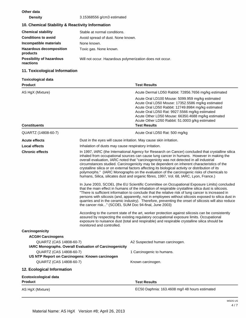
Density 3.15368556 g/cm3 estimated
10. Chemical Stability & Reactivity Information
Chemical stability Stable at normal conditions.
Conditions to avoid Avoid spread of dust. None known.
Incompatible materials None known.
Hazardous decompositionproducts
Toxic gas. None known.
Possibility of hazardous reactions
Will not occur. Hazardous polymerization does not occur.
Toxicological data
11. Toxicological Information
Product Test Results
Acute Dermal LD50 Rabbit: 72856.7656 mg/kg estimatedAS HgX (Mixture)
Acute Oral LD100 Mouse: 5099.959 mg/kg estimated Acute Oral LD50 Mouse: 17352.5586 mg/kg estimated Acute Oral LD50 Rabbit: 12749.8984 mg/kg estimated Acute Oral LD50 Rat: 9927.5566 mg/kg estimated Acute Other LD50 Mouse: 66350.4688 mg/kg estimated Acute Other LD50 Rabbit: 51.0003 g/kg estimated
Constituents Test Results
Acute Oral LD50 Rat: 500 mg/kgQUARTZ (14808-60-7)
Acute effects Dust in the eyes will cause irritation. May cause skin irritation.
Local effects Inhalation of dusts may cause respiratory irritation.
Chronic effects In 1997, IARC (the International Agency for Research on Cancer) concluded that crystalline silicainhaled from occupational sources can cause lung cancer in humans. However in making theoverall evaluation, IARC noted that "carcinogenicity was not detected in all industrialcircumstances studied. Carcinogenicity may be dependent on inherent characteristics of thecrystalline silica or on external factors affecting its biological activity or distribution of itspolymorphs." (IARC Monographs on the evaluation of the carcinogenic risks of chemicals tohumans, Silica, silicates dust and organic fibres, 1997, Vol. 68, IARC, Lyon, France.)
In June 2003, SCOEL (the EU Scientific Committee on Occupational Exposure Limits) concludedthat the main effect in humans of the inhalation of respirable crystalline silica dust is silicosis."There is sufficient information to conclude that the relative risk of lung cancer is increased inpersons with silicosis (and, apparently, not in employees without silicosis exposed to silica dust inquarries and in the ceramic industry). Therefore, preventing the onset of silicosis will also reducethe cancer risk..." (SCOEL SUM Doc 94-final, June 2003)
According to the current state of the art, worker protection against silicosis can be consistentlyassured by respecting the existing regulatory occupational exposure limits. Occupationalexposure to nuisance dust (total and respirable) and respirable crystalline silica should bemonitored and controlled.
Carcinogenicity
ACGIH Carcinogens
QUARTZ (CAS 14808-60-7) A2 Suspected human carcinogen.IARC Monographs. Overall Evaluation of Carcinogenicity
QUARTZ (CAS 14808-60-7) 1 Carcinogenic to humans.US NTP Report on Carcinogens: Known carcinogen
QUARTZ (CAS 14808-60-7) Known carcinogen.
Ecotoxicological data
12. Ecological Information
Product Test Results
EC50 Daphnia: 163.4608 mg/l 48 hours estimatedAS HgX (Mixture)
MSDS US
4 / 7
Material Name: AS HgX Version #8; April 26, 2013
Product Test Results
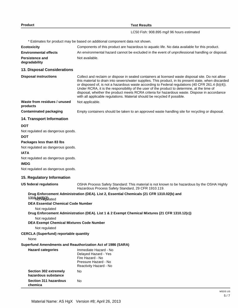
LC50 Fish: 908.895 mg/l 96 hours estimated
* Estimates for product may be based on additional component data not shown.
Ecotoxicity Components of this product are hazardous to aquatic life. No data available for this product.
Environmental effects An environmental hazard cannot be excluded in the event of unprofessional handling or disposal.
Persistence and degradability
Not available.
13. Disposal Considerations
Disposal instructions Collect and reclaim or dispose in sealed containers at licensed waste disposal site. Do not allowthis material to drain into sewers/water supplies. This product, in its present state, when discardedor disposed of, is not a hazardous waste according to Federal regulations (40 CFR 261.4 (b)(4)).Under RCRA, it is the responsibility of the user of the product to determine, at the time ofdisposal, whether the product meets RCRA criteria for hazardous waste. Dispose in accordancewith all applicable regulations. Material should be recycled if possible.
Waste from residues / unused products
Not applicable.
Contaminated packaging Empty containers should be taken to an approved waste handling site for recycling or disposal.
14. Transport Information
DOT
Not regulated as dangerous goods.
DOT
Packages less than 83 lbs
Not regulated as dangerous goods.
IATA
Not regulated as dangerous goods.
IMDG
Not regulated as dangerous goods.
15. Regulatory Information
US federal regulations OSHA Process Safety Standard: This material is not known to be hazardous by the OSHA HighlyHazardous Process Safety Standard, 29 CFR 1910.119.
Drug Enforcement Administration (DEA). List 2, Essential Chemicals (21 CFR 1310.02(b) and 1310.04(f)(2) Not regulatedDEA Essential Chemical Code Number
Not regulatedDrug Enforcement Administration (DEA). List 1 & 2 Exempt Chemical Mixtures (21 CFR 1310.12(c))
Not regulatedDEA Exempt Chemical Mixtures Code Number
Not regulated
CERCLA (Superfund) reportable quantity
None
Superfund Amendments and Reauthorization Act of 1986 (SARA)
Hazard categories Immediate Hazard - NoDelayed Hazard - YesFire Hazard - NoPressure Hazard - NoReactivity Hazard - No
Section 302 extremelyhazardous substance
No
Section 311 hazardous chemica
No
MSDS US
5 / 7
Material Name: AS HgX Version #8; April 26, 2013
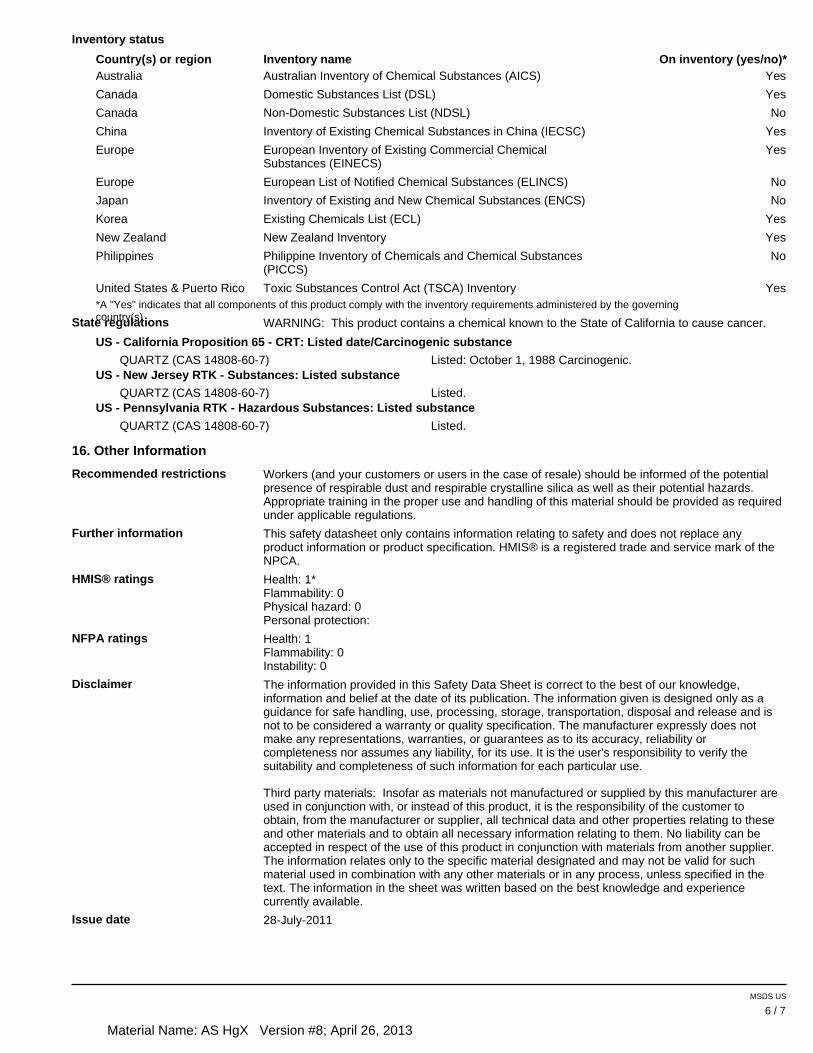
Inventory status
Country(s) or region Inventory name On inventory (yes/no)*YesAustralia Australian Inventory of Chemical Substances (AICS)
YesCanada Domestic Substances List (DSL)
NoCanada Non-Domestic Substances List (NDSL)
YesChina Inventory of Existing Chemical Substances in China (IECSC)
YesEurope European Inventory of Existing Commercial ChemicalSubstances (EINECS)
NoEurope European List of Notified Chemical Substances (ELINCS)
NoJapan Inventory of Existing and New Chemical Substances (ENCS)
YesKorea Existing Chemicals List (ECL)
YesNew Zealand New Zealand Inventory
NoPhilippines Philippine Inventory of Chemicals and Chemical Substances (PICCS)
YesUnited States & Puerto Rico Toxic Substances Control Act (TSCA) Inventory*A "Yes" indicates that all components of this product comply with the inventory requirements administered by the governingcountry(s) State regulations WARNING: This product contains a chemical known to the State of California to cause cancer.
US - California Proposition 65 - CRT: Listed date/Carcinogenic substance
QUARTZ (CAS 14808-60-7) Listed: October 1, 1988 Carcinogenic. US - New Jersey RTK - Substances: Listed substance
QUARTZ (CAS 14808-60-7) Listed.US - Pennsylvania RTK - Hazardous Substances: Listed substance
QUARTZ (CAS 14808-60-7) Listed.
16. Other Information
Recommended restrictions Workers (and your customers or users in the case of resale) should be informed of the potentialpresence of respirable dust and respirable crystalline silica as well as their potential hazards.Appropriate training in the proper use and handling of this material should be provided as requiredunder applicable regulations.
Further information This safety datasheet only contains information relating to safety and does not replace anyproduct information or product specification. HMIS® is a registered trade and service mark of theNPCA.
HMIS® ratings Health: 1*Flammability: 0Physical hazard: 0Personal protection:
NFPA ratings Health: 1 Flammability: 0Instability: 0
Disclaimer The information provided in this Safety Data Sheet is correct to the best of our knowledge,information and belief at the date of its publication. The information given is designed only as aguidance for safe handling, use, processing, storage, transportation, disposal and release and isnot to be considered a warranty or quality specification. The manufacturer expressly does notmake any representations, warranties, or guarantees as to its accuracy, reliability orcompleteness nor assumes any liability, for its use. It is the user's responsibility to verify thesuitability and completeness of such information for each particular use.
Third party materials: Insofar as materials not manufactured or supplied by this manufacturer areused in conjunction with, or instead of this product, it is the responsibility of the customer toobtain, from the manufacturer or supplier, all technical data and other properties relating to theseand other materials and to obtain all necessary information relating to them. No liability can beaccepted in respect of the use of this product in conjunction with materials from another supplier.The information relates only to the specific material designated and may not be valid for suchmaterial used in combination with any other materials or in any process, unless specified in thetext. The information in the sheet was written based on the best knowledge and experiencecurrently available.
Issue date 28-July-2011
MSDS US
6 / 7

Material Name: AS HgX Version #8; April 26, 2013
This data sheet containschanges from the previousversion in section(s):
Product and Company Identification: Alternate Trade NamesHazards Identification: Emergency overviewHazards Identification: Potential environmental effectsHazards Identification: OSHA regulatory statusToxicological InformationRegulatory Information: US federal regulationsRegulatory Information: State regulations
MSDS US
7 / 7

Rev. 10/09/13
APPENDIX C
Instructions to Bidders
Project (______) Page 1 of 6 Rev.0
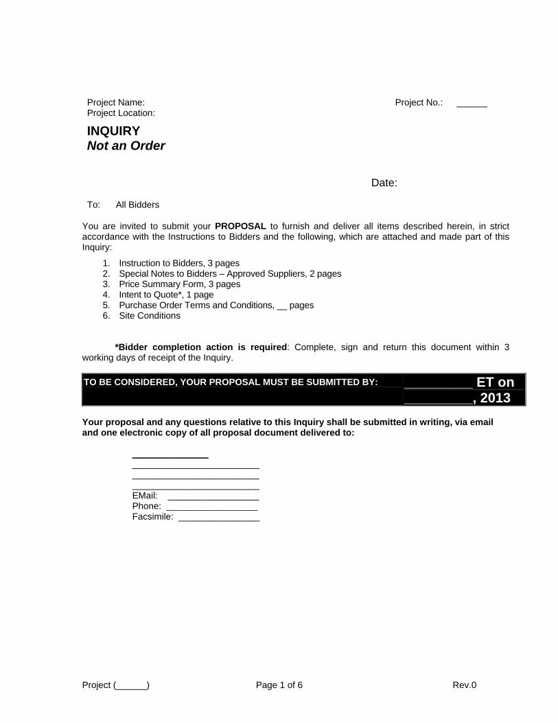
Project Name: Project No.: ______ Project Location:
To: All Bidders
You are invited to submit your PROPOSAL to furnish and deliver all items described herein, in strict accordance with the Instructions to Bidders and the following, which are attached and made part of this Inquiry:
1. Instruction to Bidders, 3 pages2. Special Notes to Bidders – Approved Suppliers, 2 pages3. Price Summary Form, 3 pages4. Intent to Quote*, 1 page5. Purchase Order Terms and Conditions, __ pages6. Site Conditions
*Bidder completion action is required: Complete, sign and return this document within 3working days of receipt of the Inquiry.
TO BE CONSIDERED, YOUR PROPOSAL MUST BE SUBMITTED BY: _________ ET on _________, 2013
Your proposal and any questions relative to this Inquiry shall be submitted in writing, via email and one electronic copy of all proposal document delivered to:
_______________ _________________________ _________________________ _________________________ EMail: __________________ Phone: __________________ Facsimile: ________________
INQUIRY Not an Order
Date:
Project (______) Page 2 of 6 Rev.0
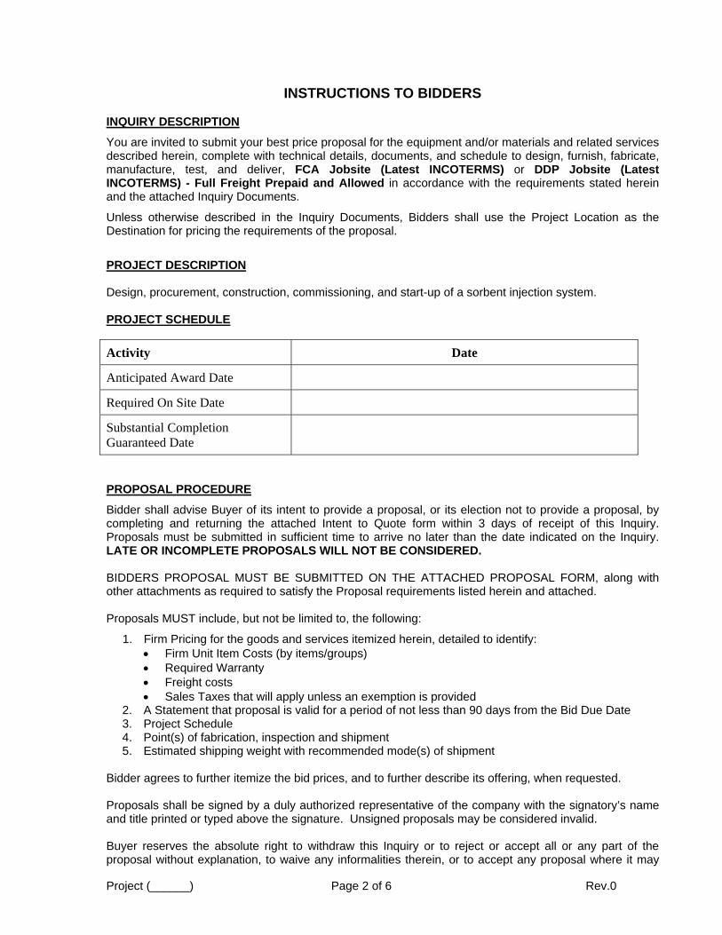
INSTRUCTIONS TO BIDDERS
INQUIRY DESCRIPTION
You are invited to submit your best price proposal for the equipment and/or materials and related services described herein, complete with technical details, documents, and schedule to design, furnish, fabricate, manufacture, test, and deliver, FCA Jobsite (Latest INCOTERMS) or DDP Jobsite (Latest INCOTERMS) - Full Freight Prepaid and Allowed in accordance with the requirements stated herein and the attached Inquiry Documents.
Unless otherwise described in the Inquiry Documents, Bidders shall use the Project Location as the Destination for pricing the requirements of the proposal.
PROJECT DESCRIPTION
Design, procurement, construction, commissioning, and start-up of a sorbent injection system.
PROJECT SCHEDULE
Activity Date
Anticipated Award Date
Required On Site Date
Substantial Completion Guaranteed Date
PROPOSAL PROCEDURE
Bidder shall advise Buyer of its intent to provide a proposal, or its election not to provide a proposal, by completing and returning the attached Intent to Quote form within 3 days of receipt of this Inquiry. Proposals must be submitted in sufficient time to arrive no later than the date indicated on the Inquiry. LATE OR INCOMPLETE PROPOSALS WILL NOT BE CONSIDERED.
BIDDERS PROPOSAL MUST BE SUBMITTED ON THE ATTACHED PROPOSAL FORM, along with other attachments as required to satisfy the Proposal requirements listed herein and attached.
Proposals MUST include, but not be limited to, the following:
1. Firm Pricing for the goods and services itemized herein, detailed to identify: Firm Unit Item Costs (by items/groups) Required Warranty Freight costs Sales Taxes that will apply unless an exemption is provided
2. A Statement that proposal is valid for a period of not less than 90 days from the Bid Due Date3. Project Schedule4. Point(s) of fabrication, inspection and shipment5. Estimated shipping weight with recommended mode(s) of shipment
Bidder agrees to further itemize the bid prices, and to further describe its offering, when requested.
Proposals shall be signed by a duly authorized representative of the company with the signatory’s name and title printed or typed above the signature. Unsigned proposals may be considered invalid.
Buyer reserves the absolute right to withdraw this Inquiry or to reject or accept all or any part of the proposal without explanation, to waive any informalities therein, or to accept any proposal where it may
Project (______) Page 3 of 6 Rev.0
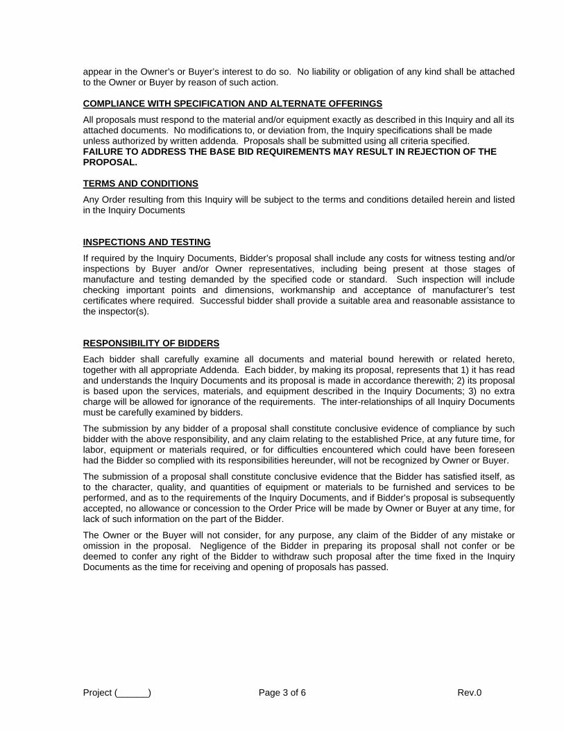
appear in the Owner’s or Buyer’s interest to do so. No liability or obligation of any kind shall be attached to the Owner or Buyer by reason of such action.
COMPLIANCE WITH SPECIFICATION AND ALTERNATE OFFERINGS
All proposals must respond to the material and/or equipment exactly as described in this Inquiry and all its attached documents. No modifications to, or deviation from, the Inquiry specifications shall be made unless authorized by written addenda. Proposals shall be submitted using all criteria specified. FAILURE TO ADDRESS THE BASE BID REQUIREMENTS MAY RESULT IN REJECTION OF THE PROPOSAL.
TERMS AND CONDITIONS
Any Order resulting from this Inquiry will be subject to the terms and conditions detailed herein and listed in the Inquiry Documents
INSPECTIONS AND TESTING
If required by the Inquiry Documents, Bidder’s proposal shall include any costs for witness testing and/or inspections by Buyer and/or Owner representatives, including being present at those stages of manufacture and testing demanded by the specified code or standard. Such inspection will include checking important points and dimensions, workmanship and acceptance of manufacturer’s test certificates where required. Successful bidder shall provide a suitable area and reasonable assistance to the inspector(s).
RESPONSIBILITY OF BIDDERS
Each bidder shall carefully examine all documents and material bound herewith or related hereto, together with all appropriate Addenda. Each bidder, by making its proposal, represents that 1) it has read and understands the Inquiry Documents and its proposal is made in accordance therewith; 2) its proposal is based upon the services, materials, and equipment described in the Inquiry Documents; 3) no extra charge will be allowed for ignorance of the requirements. The inter-relationships of all Inquiry Documents must be carefully examined by bidders.
The submission by any bidder of a proposal shall constitute conclusive evidence of compliance by such bidder with the above responsibility, and any claim relating to the established Price, at any future time, for labor, equipment or materials required, or for difficulties encountered which could have been foreseen had the Bidder so complied with its responsibilities hereunder, will not be recognized by Owner or Buyer.
The submission of a proposal shall constitute conclusive evidence that the Bidder has satisfied itself, as to the character, quality, and quantities of equipment or materials to be furnished and services to be performed, and as to the requirements of the Inquiry Documents, and if Bidder’s proposal is subsequently accepted, no allowance or concession to the Order Price will be made by Owner or Buyer at any time, for lack of such information on the part of the Bidder.
The Owner or the Buyer will not consider, for any purpose, any claim of the Bidder of any mistake or omission in the proposal. Negligence of the Bidder in preparing its proposal shall not confer or be deemed to confer any right of the Bidder to withdraw such proposal after the time fixed in the Inquiry Documents as the time for receiving and opening of proposals has passed.
Project (______) Page 4 of 6 Rev.0
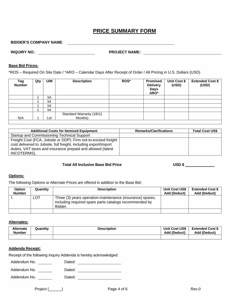
PRICE SUMMARY FORM
BIDDER’S COMPANY NAME:
INQUIRY NO.: PROJECT NAME:
Base Bid Prices:
*ROS – Required On Site Date / *ARO – Calendar Days After Receipt of Order / All Pricing in U.S. Dollars (USD)
Tag Number
Qty U/M Description ROS* Promised Delivery
Days ARO*
Unit Cost $ (USD)
Extended Cost $(USD)
1 lot1 lot1 lot1 lot
N/A 1 Lot Standard Warranty (18/12
Months)
Additional Costs for Itemized Equipment Remarks/Clarifications Total Cost US$Startup and Commissioning Technical Support Freight Cost (FCA, Jobsite or DDP): Firm not-to-exceed freight cost delivered to Jobsite, full freight, including export/import duties, VAT taxes and insurance prepaid and allowed (latest INCOTERMS).
Total All Inclusive Base Bid Price USD $
Options:
The following Options or Alternate Prices are offered in addition to the Base Bid:
Option Number
Quantity Description Unit Cost US$ Add (Deduct)
Extended Cost $Add (Deduct)
1 LOT Three (3) years operation-maintenance (insurance) spares, including required spare parts catalogs recommended by Bidder.
Alternates:
Alternate Number
Quantity Description Unit Cost US$ Add (Deduct)
Extended Cost $Add (Deduct)
Addenda Receipt:
Receipt of the following Inquiry Addenda is hereby acknowledged:
Addendum No. Dated:
Addendum No. Dated:
Addendum No. Dated:

Project (______) Page 5 of 6 Rev.0
Proposal Contents:
In addition to this Proposal Form, Bidders proposal consists of the following (insert Attachment Number/Title and Date):
Document Submittal:
Approval Drawings on or before: days ARO Certified/Record Drawings on or before: days ARO
Delivery Complete:
Complete delivery to the location specified in the Inquiry Documents on or before ________days ARO
Additional Terms and Provisions:
Bid Validity Period: 90 days after bid date FCA / DDP Point: Freight:
Payment Terms: Shipping Points: Shipping Method: Estimated Shipping Weight: Heaviest Component / Container: Number of Shipments:
Agreement to Accept the Terms and Provisions of the Inquiry Documents:
We have reviewed the provisions of the Inquiry, the Inquiry Documents attached to the Inquiry, and the Addenda received and agree to accept the provisions without exception on any Order resulting from this Inquiry.
YES NO
If NO, our exceptions are listed below or on a separate document attached hereto. We understand that exceptions may be grounds for rejection of the proposal:
Technical Exceptions:
Commercial Exceptions:

Project (______) Page 6 of 6 Rev.0
INTENT TO QUOTE
RETURN IMMEDIATELY VIA FAX OR E-MAIL
TO: __________________
E-MAIL: ___________________
FACSIMILE NO: _____________
PROJECT: ___________________
INQUIRY NO: ____________
INQUIRY TITLE: ASI
QUOTE DUE : By ___________ ET on _________________, 2012
We have received your INQUIRY invitation and will submit our Quotation on or before the required due date.
YES NO
If NO, please state reason:
(Please print the following information:) (Representing Manufacturer, if applicable:)
COMPANY:
CONTACT: TITLE:
DATE: PHONE: FAX:
Rev. 10/09/13
APPENDIX D
Terms and Conditions
Provided by Owner
Rev. 10/09/13
APPENDIX E
Facility Details
Provided by Owner

Rev. 10/09/13
APPENDIX F
Lance Details
PLAN VIEW
04 PIPE PORT
TO SUIT TEST PORT NIPPLE
INLET PIPING AND FLANGE
TB
D
A A
T
BD
TB
D
SEE DETAIL 1
C C
B B
AIR PIPE
SORBENT & CARRIER
TB
D
FLOW TB
D
T
BD
01-1/4" & 02" SCH 40 PIPE
SORBENT & CARRIER AIR SUPPLYL3"X3" 1/4"X11’-0"
FLOW
04" SCH 40 PIPE PORT
LANCE TO FIT IN
TRIMMED IN ORDER FOR
ANGLE EDGES TO BE
3/16"
B/S
TYP
1/4
NESTED PIPE CONFIGURATION
PLACE @ END OF 02" PIPE
4 PLC’S TACK WELDED IN
1X3/16"X1/8" SPACER TAB TYP
VIEW A-A
RIB 1/4"X3/8"X4’ LG
1/8 3-12
01-1/4 SCH 40 PIPE
FLOW
FLOW
1 11/16
"X10’ 10
"
1 3/16"
VIEW B-B
VIEW C-C
1/8
45°
01-1/4"SCH 40 PIPE
DETAIL 1
1/8
1/8
3-12
3-9
SK-00006
TYPICAL LANCE DESIGN
DRY SORBENT INJECTION
NONE
08/28/13
08/28/13 AAH
.
.
.
.
.
.
.
.
.
.
_______ - ____
08/28/130
0
0
ISSUED TO CLIENT0
THIS D
OC
UM
EN
T,
AN
D T
HE I
DE
AS A
ND D
ESIG
NS I
NC
OR
PO
RA
TE
D H
ER
EIN,
AS A
N I
NS
TR
UM
EN
T O
F P
RO
FE
SSIO
NA
L S
ER
VIC
E, IS T
HE P
RO
PE
RT
Y O
FC
H2
M HIL
L A
ND IS N
OT T
O B
E U
SE
D, IN W
HO
LE O
R I
N P
AR
T, F
OR A
NY O
TH
ER P
ROJE
CT W
ITH
OU
T T
HE W
RIT
TE
N A
UT
HO
RIZ
ATIO
N O
F C
H2
MHIL
L.
RE
US
E O
F D
OC
UM
EN
TS:
C
A
B
C
D
NO. REVISIONDATE
c
D
A
B
654321
CH2
M
HIL
L
FILENAME: PLOT DATE:
REV
DISCIPLINE
CIVIL
STRUCTURAL
MECHANICAL
PROCESS
DISCIPLINE
PIPING
ELECTRICAL
REVIEWED REVIEWED
REVISION APPROVAL DATE
REV.
PE #
SCALE
DATE
STATUS
FOR CONSTRUCTION
REVISED & APPROVED
CONSTRUCTION
APPROVED FOR
ISSUED REV SDE PEM
RE
SP
ON
SI
BL
E
EN
GI
NE
ER
DM
BY CHK
INST & CNTRL
PROJECT NO.
DWG. NO.
421334PLANT LAYOUTS
ARCHITECTURAL
CH2MHILL Engineers, Inc.
ISSUED TO CLIENT
APPROVAL
FOR REVIEW AND

Rev. 10/09/13
APPENDIX G
Jenike & Johanson
Typical Silo Design for Amended Silicates and Powdered Activated
Carbon
TYPICAL - NOT FOR CONSTRUCTION
FOR INFORMATION ONLY
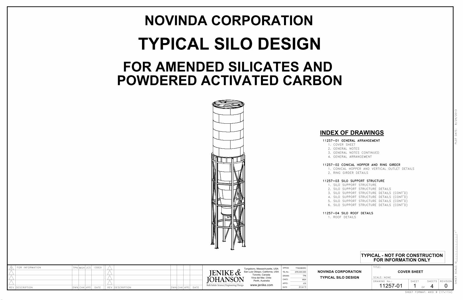
TYPICAL SILO DESIGN
NOVINDA CORPORATION
FOR AMENDED SILICATES AND
POWDERED ACTIVATED CARBON
INDEX OF DRAWINGS
11257-01 GENERAL ARRANGEMENT11257-01 GENERAL ARRANGEMENT11257-01 GENERAL ARRANGEMENT11257-01 GENERAL ARRANGEMENTCOVER SHEET1.GENERAL NOTES2.GENERAL NOTES CONTINUED3.GENERAL ARRANGEMENT4.
11257-02 CONICAL HOPPER AND RING GIRDER11257-02 CONICAL HOPPER AND RING GIRDER11257-02 CONICAL HOPPER AND RING GIRDER11257-02 CONICAL HOPPER AND RING GIRDERCONICAL HOPPER AND VERTICAL OUTLET DETAILS1.
2. RING GIRDER DETAILS
11257-03 SILO SUPPORT STRUCTURE11257-03 SILO SUPPORT STRUCTURE11257-03 SILO SUPPORT STRUCTURE11257-03 SILO SUPPORT STRUCTURESILO SUPPORT STRUCTURE1.SILO SUPPORT STRUCTURE DETAILS2.SILO SUPPORT STRUCTURE DETAILS (CONT'D)3.SILO SUPPORT STRUCTURE DETAILS (CONT'D)4.SILO SUPPORT STRUCTURE DETAILS (CONT'D)5.SILO SUPPORT STRUCTURE DETAILS (CONT'D)6.
11257-04 SILO ROOF DETAILS11257-04 SILO ROOF DETAILS11257-04 SILO ROOF DETAILS11257-04 SILO ROOF DETAILS1. ROOF DETAILS
MGH
24 Jun 13 0
TYPICAL SILO DESIGN
TYNGSBORO
TPN
11257-01
(978) 649-3300
4
NOVINDA CORPORATION
JCS
Perth, Australia
OF
DRAWING No.:
SCALE:
www.jenike.com
REVISION
TITLE:Tyngsboro, Massachusetts, USA
San Luis Obispo, California, USA
Toronto, Canada
Vina del Mar, Chile
SHEET FORMAT:
NONE
COVER SHEET
TPN JCS0 MGHFOR INFORMATION
1
130829
1"
SHEET SHEETS
DATEAPPDCHKDESCRIPTIONREV DWNDATECHK APPDDESCRIPTION DWNREV
TEL No.:
OFFICE:
APP'D:
DRAWN:
DATE:
CHK'D:
ANSI B (17x11in)
0
Bulk Solids: Science/Engineering/Design
SHEET SCALE:
PLOT DATE: 8/29/2013
JOHANSONJENIKE &
TYPICAL - NOT FOR CONSTRUCTION
FOR INFORMATION ONLY
General Notes
(978) 649-3300
11257-01
NONE
0
TYPICAL SILO DESIGN
TYNGSBORO
TPN
24 Jun 13
MGH
4
NOVINDA CORPORATION
JCS
Perth, Australia
OF
DRAWING No.:
SCALE:
www.jenike.com
REVISION
TITLE:Tyngsboro, Massachusetts, USA
San Luis Obispo, California, USA
Toronto, Canada
Vina del Mar, Chile
SHEET FORMAT:
130829
GENERAL NOTES
2
FOR INFORMATION MGH0 JCSTPN
1"
SHEET SHEETS
DATEAPPDCHKDESCRIPTIONREV DWNDATECHK APPDDESCRIPTION DWNREV
TEL No.:
OFFICE:
APP'D:
DRAWN:
DATE:
CHK'D:
ANSI B (17x11in)
0
Bulk Solids: Science/Engineering/Design
SHEET SCALE:
PLOT DATE: 8/29/2013
JOHANSONJENIKE &
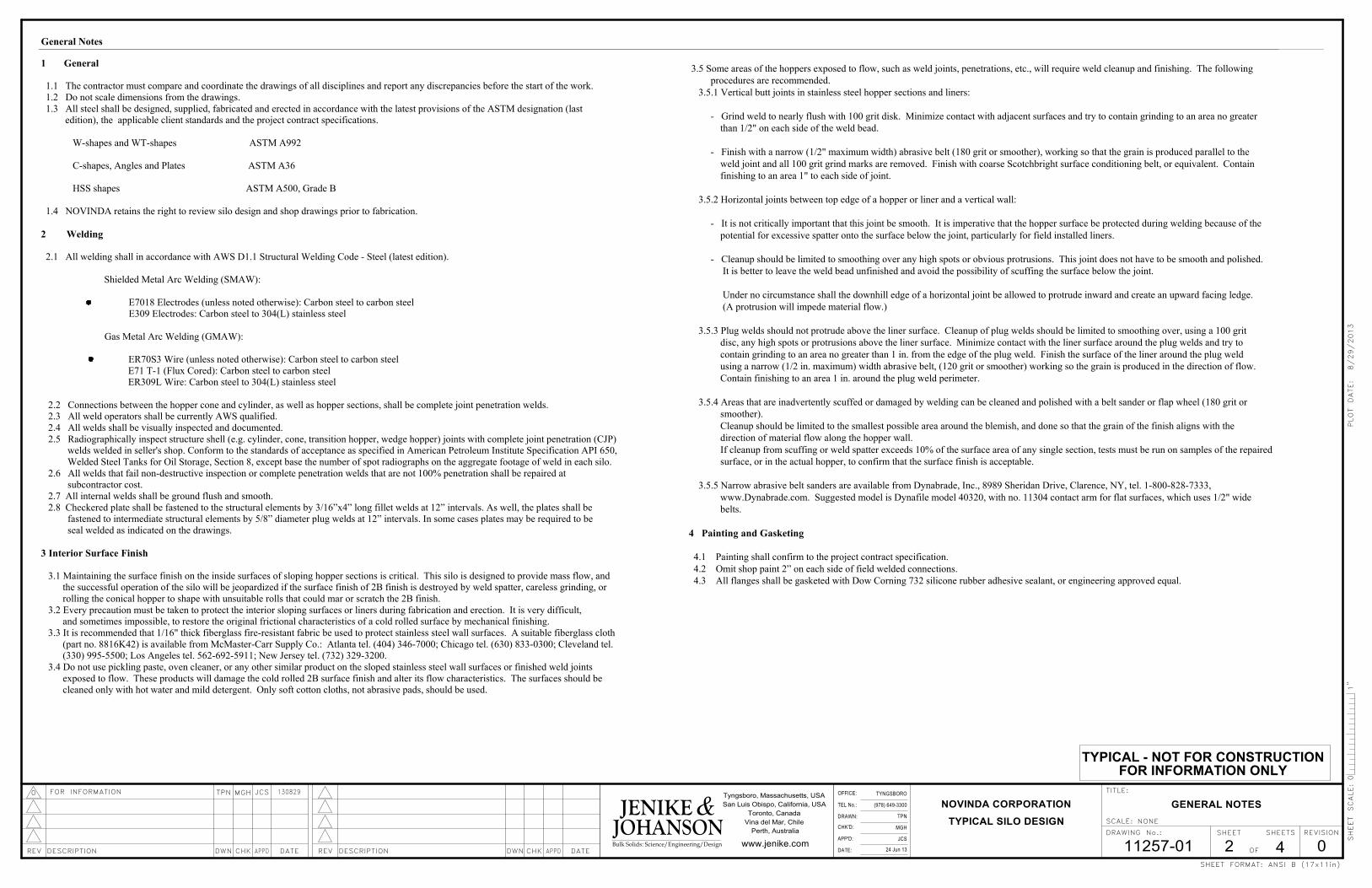
3.5 Some areas of the hoppers exposed to flow, such as weld joints, penetrations, etc., will require weld cleanup and finishing. The following
procedures are recommended.
3.5.1 Vertical butt joints in stainless steel hopper sections and liners:
- Grind weld to nearly flush with 100 grit disk. Minimize contact with adjacent surfaces and try to contain grinding to an area no greater
than 1/2" on each side of the weld bead.
- Finish with a narrow (1/2" maximum width) abrasive belt (180 grit or smoother), working so that the grain is produced parallel to the
weld joint and all 100 grit grind marks are removed. Finish with coarse Scotchbright surface conditioning belt, or equivalent. Contain
finishing to an area 1" to each side of joint.
3.5.2 Horizontal joints between top edge of a hopper or liner and a vertical wall:
- It is not critically important that this joint be smooth. It is imperative that the hopper surface be protected during welding because of the
potential for excessive spatter onto the surface below the joint, particularly for field installed liners.
- Cleanup should be limited to smoothing over any high spots or obvious protrusions. This joint does not have to be smooth and polished.
It is better to leave the weld bead unfinished and avoid the possibility of scuffing the surface below the joint.
Under no circumstance shall the downhill edge of a horizontal joint be allowed to protrude inward and create an upward facing ledge.
(A protrusion will impede material flow.)
3.5.3 Plug welds should not protrude above the liner surface. Cleanup of plug welds should be limited to smoothing over, using a 100 grit
disc, any high spots or protrusions above the liner surface. Minimize contact with the liner surface around the plug welds and try to
contain grinding to an area no greater than 1 in. from the edge of the plug weld. Finish the surface of the liner around the plug weld
using a narrow (1/2 in. maximum) width abrasive belt, (120 grit or smoother) working so the grain is produced in the direction of flow.
Contain finishing to an area 1 in. around the plug weld perimeter.
3.5.4 Areas that are inadvertently scuffed or damaged by welding can be cleaned and polished with a belt sander or flap wheel (180 grit or
smoother).
Cleanup should be limited to the smallest possible area around the blemish, and done so that the grain of the finish aligns with the
direction of material flow along the hopper wall.
If cleanup from scuffing or weld spatter exceeds 10% of the surface area of any single section, tests must be run on samples of the repaired
surface, or in the actual hopper, to confirm that the surface finish is acceptable.
3.5.5 Narrow abrasive belt sanders are available from Dynabrade, Inc., 8989 Sheridan Drive, Clarence, NY, tel. 1-800-828-7333,
www.Dynabrade.com. Suggested model is Dynafile model 40320, with no. 11304 contact arm for flat surfaces, which uses 1/2" wide
belts.
4 Painting and Gasketing
4.1 Painting shall confirm to the project contract specification.
4.2 Omit shop paint 2” on each side of field welded connections.
4.3 All flanges shall be gasketed with Dow Corning 732 silicone rubber adhesive sealant, or engineering approved equal.
3.2 Every precaution must be taken to protect the interior sloping surfaces or liners during fabrication and erection. It is very difficult, and sometimes impossible, to restore the original frictional characteristics of a cold rolled surface by mechanical finishing.
3.3 It is recommended that 1/16" thick fiberglass fire-resistant fabric be used to protect stainless steel wall surfaces. A suitable fiberglass cloth
(part no. 8816K42) is available from McMaster-Carr Supply Co.: Atlanta tel. (404) 346-7000; Chicago tel. (630) 833-0300; Cleveland tel. (330) 995-5500; Los Angeles tel. 562-692-5911; New Jersey tel. (732) 329-3200.
3.4 Do not use pickling paste, oven cleaner, or any other similar product on the sloped stainless steel wall surfaces or finished weld joints
exposed to flow. These products will damage the cold rolled 2B surface finish and alter its flow characteristics. The surfaces should be cleaned only with hot water and mild detergent. Only soft cotton cloths, not abrasive pads, should be used.
rolling the conical hopper to shape with unsuitable rolls that could mar or scratch the 2B finish.
the successful operation of the silo will be jeopardized if the surface finish of 2B finish is destroyed by weld spatter, careless grinding, or 3.1 Maintaining the surface finish on the inside surfaces of sloping hopper sections is critical. This silo is designed to provide mass flow, and
3 Interior Surface Finish
seal welded as indicated on the drawings.
fastened to intermediate structural elements by 5/8” diameter plug welds at 12” intervals. In some cases plates may be required to be 2.8 Checkered plate shall be fastened to the structural elements by 3/16”x4” long fillet welds at 12” intervals. As well, the plates shall be
2.7 All internal welds shall be ground flush and smooth.
subcontractor cost. 2.6 All welds that fail non-destructive inspection or complete penetration welds that are not 100% penetration shall be repaired at
Welded Steel Tanks for Oil Storage, Section 8, except base the number of spot radiographs on the aggregate footage of weld in each silo.
welds welded in seller's shop. Conform to the standards of acceptance as specified in American Petroleum Institute Specification API 650, 2.5 Radiographically inspect structure shell (e.g. cylinder, cone, transition hopper, wedge hopper) joints with complete joint penetration (CJP)
2.4 All welds shall be visually inspected and documented.
2.3 All weld operators shall be currently AWS qualified. 2.2 Connections between the hopper cone and cylinder, as well as hopper sections, shall be complete joint penetration welds.
ER309L Wire: Carbon steel to 304(L) stainless steel E71 T-1 (Flux Cored): Carbon steel to carbon steel
ER70S3 Wire (unless noted otherwise): Carbon steel to carbon steel
Gas Metal Arc Welding (GMAW):
1 General
1.1 The contractor must compare and coordinate the drawings of all disciplines and report any discrepancies before the start of the work.
1.2 Do not scale dimensions from the drawings.
1.3 All steel shall be designed, supplied, fabricated and erected in accordance with the latest provisions of the ASTM designation (last edition), the applicable client standards and the project contract specifications.
W-shapes and WT-shapes ASTM A992
C-shapes, Angles and Plates ASTM A36
HSS shapes ASTM A500, Grade B
1.4 NOVINDA retains the right to review silo design and shop drawings prior to fabrication.
2 Welding
2.1 All welding shall in accordance with AWS D1.1 Structural Welding Code - Steel (latest edition).
Shielded Metal Arc Welding (SMAW):
E7018 Electrodes (unless noted otherwise): Carbon steel to carbon steel E309 Electrodes: Carbon steel to 304(L) stainless steel
TYPICAL - NOT FOR CONSTRUCTION
FOR INFORMATION ONLY
TYNGSBORO
(978) 649-3300
11257-0124 Jun 13 0
TPN
MGHNONE
4
NOVINDA CORPORATION
TYPICAL SILO DESIGN
JCS
TITLE:
Perth, Australia
OF
DRAWING No.:
SCALE:
www.jenike.com
REVISION
Tyngsboro, Massachusetts, USA
San Luis Obispo, California, USA
Toronto, Canada
Vina del Mar, Chile
SHEET FORMAT:
130829
GENERAL NOTES CONTINUED
3
FOR INFORMATION JCSMGH0 TPN
JOHANSON
1"
SHEET SHEETS
DATEAPPDCHKDESCRIPTIONREV DWNDATECHK APPDDESCRIPTION DWNREV
TEL No.:
OFFICE:
APP'D:
DRAWN:
DATE:
CHK'D:
ANSI B (17x11in)
0
Bulk Solids: Science/Engineering/Design
SHEET SCALE:
PLOT DATE: 8/29/2013
JENIKE &
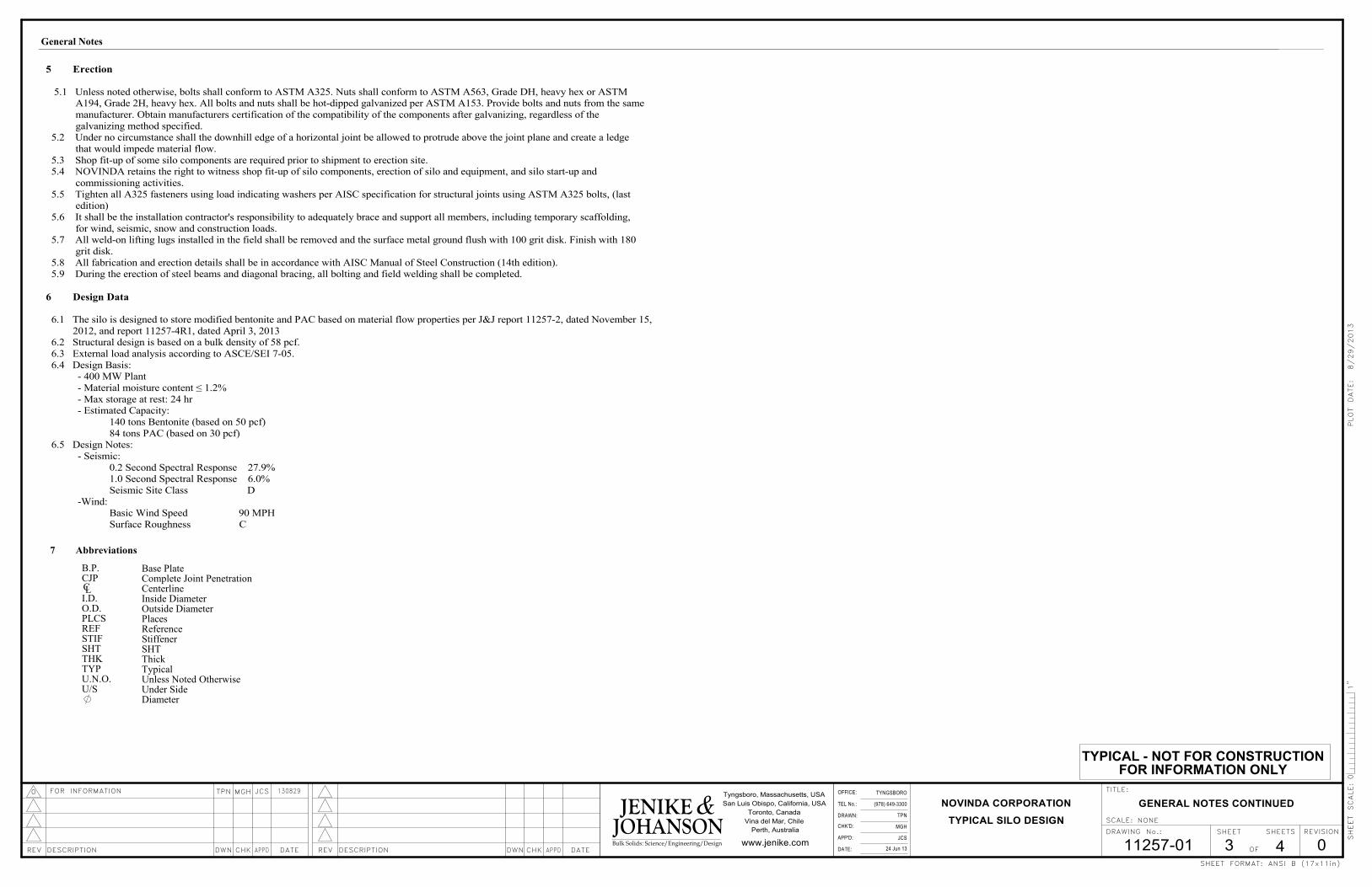
5 Erection
5.1 Unless noted otherwise, bolts shall conform to ASTM A325. Nuts shall conform to ASTM A563, Grade DH, heavy hex or ASTM A194, Grade 2H, heavy hex. All bolts and nuts shall be hot-dipped galvanized per ASTM A153. Provide bolts and nuts from the same
manufacturer. Obtain manufacturers certification of the compatibility of the components after galvanizing, regardless of the
galvanizing method specified. 5.2 Under no circumstance shall the downhill edge of a horizontal joint be allowed to protrude above the joint plane and create a ledge
that would impede material flow.
5.3 Shop fit-up of some silo components are required prior to shipment to erection site. 5.4 NOVINDA retains the right to witness shop fit-up of silo components, erection of silo and equipment, and silo start-up and
commissioning activities.
5.5 Tighten all A325 fasteners using load indicating washers per AISC specification for structural joints using ASTM A325 bolts, (last edition)
5.6 It shall be the installation contractor's responsibility to adequately brace and support all members, including temporary scaffolding,
for wind, seismic, snow and construction loads. 5.7 All weld-on lifting lugs installed in the field shall be removed and the surface metal ground flush with 100 grit disk. Finish with 180
grit disk.
5.8 All fabrication and erection details shall be in accordance with AISC Manual of Steel Construction (14th edition). 5.9 During the erection of steel beams and diagonal bracing, all bolting and field welding shall be completed.
6 Design Data
6.1 The silo is designed to store modified bentonite and PAC based on material flow properties per J&J report 11257-2, dated November 15,
2012, and report 11257-4R1, dated April 3, 2013 6.2 Structural design is based on a bulk density of 58 pcf.
6.3 External load analysis according to ASCE/SEI 7-05.
6.4 Design Basis:- 400 MW Plant
- Material moisture content ≤ 1.2%
- Max storage at rest: 24 hr- Estimated Capacity:
140 tons Bentonite (based on 50 pcf)
84 tons PAC (based on 30 pcf) 6.5 Design Notes:
- Seismic:
0.2 Second Spectral Response 27.9%1.0 Second Spectral Response 6.0%
Seismic Site Class D
-Wind:Basic Wind Speed 90 MPH
Surface Roughness C
B.P.
I.D.CL
CJP
O.D.PLCSREFSTIFSHTTHKTYPU.N.O.U/S
General Notes
7 Abbreviations
Base PlateComplete Joint PenetrationCenterlineInside DiameterOutside DiameterPlacesReferenceStiffenerSHTThickTypicalUnless Noted OtherwiseUnder SideDiameter
TYPICAL - NOT FOR CONSTRUCTION
FOR INFORMATION ONLY
RING GIRDER,
SEE DWG 11257-02
11257-0124 Jun 13 0
TYPICAL SILO DESIGN
TYNGSBORO
(978) 649-3300
TPN
MGH
4
NOVINDA CORPORATION
JCS
Perth, Australia
OF
DRAWING No.:
SCALE:
www.jenike.com
REVISION
TITLE:Tyngsboro, Massachusetts, USA
San Luis Obispo, California, USA
Toronto, Canada
Vina del Mar, Chile
SHEET FORMAT:
AS SHOWN
GENERAL ARRANGEMENT
TPN JCS0 MGHFOR INFORMATION
4
130829
1"
SHEET SHEETS
DATEAPPDCHKDESCRIPTIONREV DWNDATECHK APPDDESCRIPTION DWNREV
TEL No.:
OFFICE:
APP'D:
DRAWN:
DATE:
CHK'D:
ANSI B (17x11in)
0
Bulk Solids: Science/Engineering/Design
SHEET SCALE:
PLOT DATE: 8/29/2013
JOHANSONJENIKE &
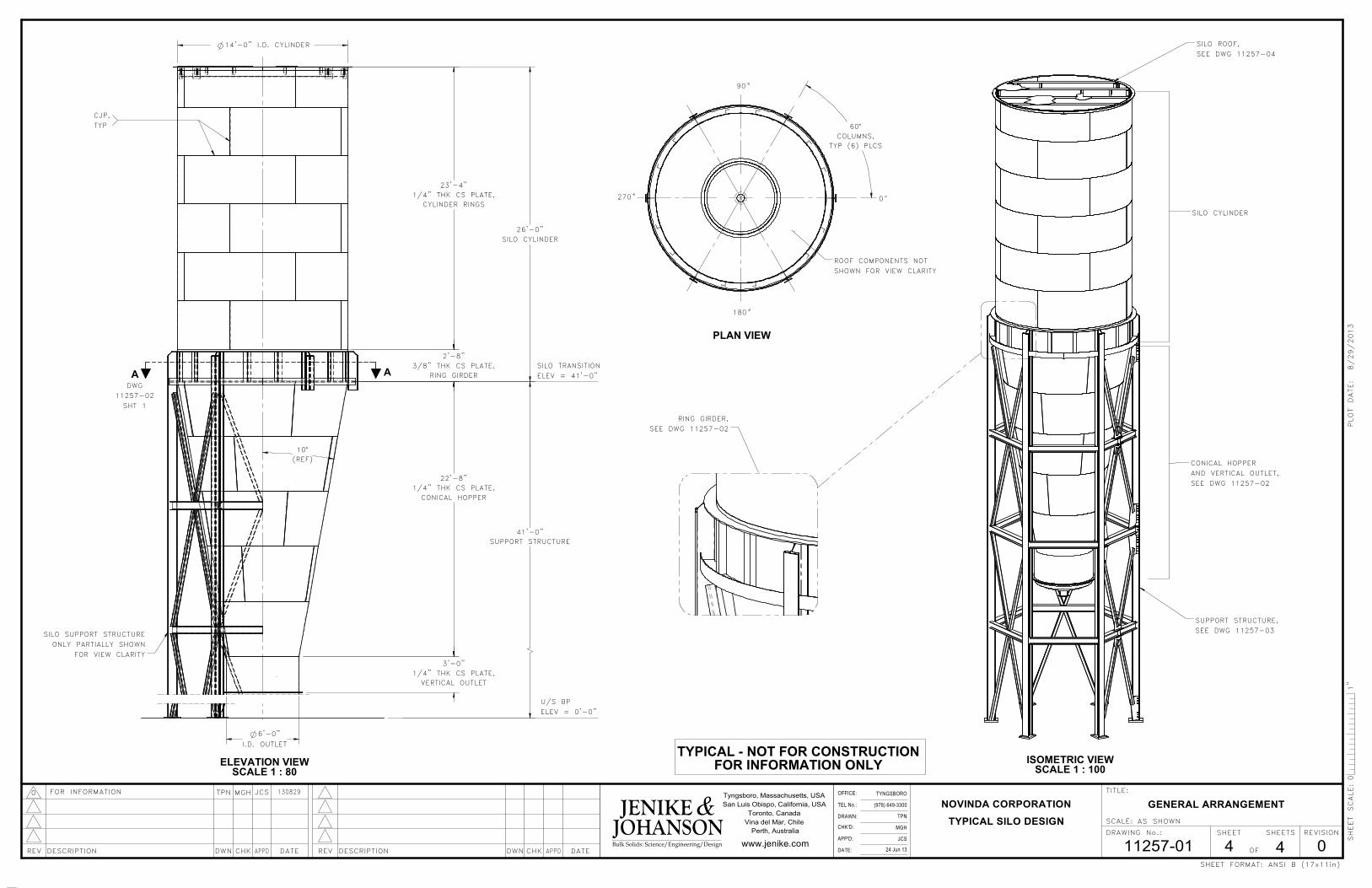
270 0
PLAN VIEW
180
90
ROOF COMPONENTS NOT
SHOWN FOR VIEW CLARITY
60°
COLUMNS,
TYP (6) PLCS
SILO CYLINDER
SEE DWG 11257-02
SEE DWG 11257-03
SUPPORT STRUCTURE,
AND VERTICAL OUTLET,
ISOMETRIC VIEW
SCALE 1 : 100
CONICAL HOPPER
SILO ROOF,
SEE DWG 11257-04
ONLY PARTIALLY SHOWN
FOR VIEW CLARITY
CJP,
SCALE 1 : 80
ELEVATION VIEW
DWG
SILO TRANSITION
ELEV = 0'-0"
SHT 1
SILO SUPPORT STRUCTURE
ELEV = 41'-0"
U/S BP
TYP
11257-02
3/8" THK CS PLATE,
2'-8"
RING GIRDER
SILO CYLINDER
26'-0"
VERTICAL OUTLET
1/4" THK CS PLATE,
3'-0"
14'-0" I.D. CYLINDER
1/4" THK CS PLATE,
23'-4"
6'-0"
I.D. OUTLET
CYLINDER RINGS
41'-0"
SUPPORT STRUCTURE
22'-8"
1/4" THK CS PLATE,
CONICAL HOPPER
A A
10°
(REF)
10°
REF
1 1/4" MAX.
SEE MEC. DWG
20°
ANGLE STIF SPACING,
TYP (12) PLCS
60°
SUPPORT COLUMN
SPACING, TYP
(6) PLCS
TYPICAL - NOT FOR CONSTRUCTIONFOR INFORMATION ONLY
D2
D1TYPICAL AIR ASSISTED DISCHARGER
ARRANGEMENT DEPENDS ON MFG
SPECIFICATION
SECTION B-B
CONICAL HOPPER ELEVATION
SHT 2
6'-0" I.D. OUTLET
22'-8"
1/4" THK CS PLATE,
CONICAL HOPPER
3'-0"
1/4" THK CS PLATE,
VERTICAL OUTLET
2'-8"
RING GIRDER
AT CYLINDER
1/2" THK CS
FLANGE
14'-0" I.D.
AA
C C
SECTION C-C
OUTLET MATING FLANGE
6'-6 1/2"
O.D. FLANGE
MIN. (40) 13/16" THRU HOLES
EQ. SPACED ON MAX 6'-3" BOLT
CIRCLE FOR 3/4" HEX HD,
GRADE 5, ZINC PLATED BOLTS,
SEE AIR ASSISTED DISCHARGER DWG
CLBOLT
SCALE 1 : 6DETAIL D1
OUTLET FLANGE WELD
3/16
3/16
1/4" GAP
MIN. 1/2" THK CS
PLATE FLANGE, SEE
MEC. DWG
CJP,TYP
SILO CYLINDER PLATE,
SCALE 1 :80ISOMETRIC VIEW
SHEET 2 FOR DETAILS
CONICAL HOPPER
VERTICAL OUTLET
RING GIRDER, SEE
1/2" THK CS PLATE
OUTLET FLANGE,
(SHOWN HERE FOR REF ONLY),
SEE DWG 11257-02
SHT 2
CL
DWG 11257-01, SHT 3SECTION A-A
90
0
180
270
CL COLUMN
CL ANGLE STIF
CL COLUMNCL COLUMN
CL COLUMNCL COLUMN
COLUMN
ALL INTERIOR SLOPING SURFACES SHALL BE LINED
WITH 304 #2B FINISH STAINLESS STEEL SHEET.
(WELDING AND OTHER SPECIFICATIONS TO BE
DESIGNED)
B B
D
D
11257-02 0
TYPICAL SILO DESIGN
NOVINDA CORPORATION
224 Jun 13
TPN
(978) 649-3300
TYNGSBORO
MGH
JCS
OF
DRAWING No.:
SCALE:
www.jenike.com
REVISION
TITLE:Tyngsboro, Massachusetts, USA
San Luis Obispo, California, USA
Toronto, Canada
Vina del Mar, Chile
Perth, Australia
SHEET FORMAT:
1:50 UNO
CONICAL HOPPER AND
VERTICAL OUTLET DETAILS
TPN JCS0 MGHFOR INFORMATION
1
130829
SHEET SHEETS
DATEAPPDCHKDESCRIPTIONREV DWNDATECHK APPDDESCRIPTION DWNREV
TEL No.:
OFFICE:
APP'D:
DRAWN:
DATE:
CHK'D:
ANSI B (17x11in)
01"
SHEET SCALE:
PLOT DATE: 8/29/2013
JOHANSON Bulk Solids: Science/Engineering/Design
JENIKE &
NOTE:
1. DETAIL NUMBERS ARE FOR DRAWINGS 11257-02.
TYPICAL - NOT FOR CONSTRUCTIONFOR INFORMATION ONLY
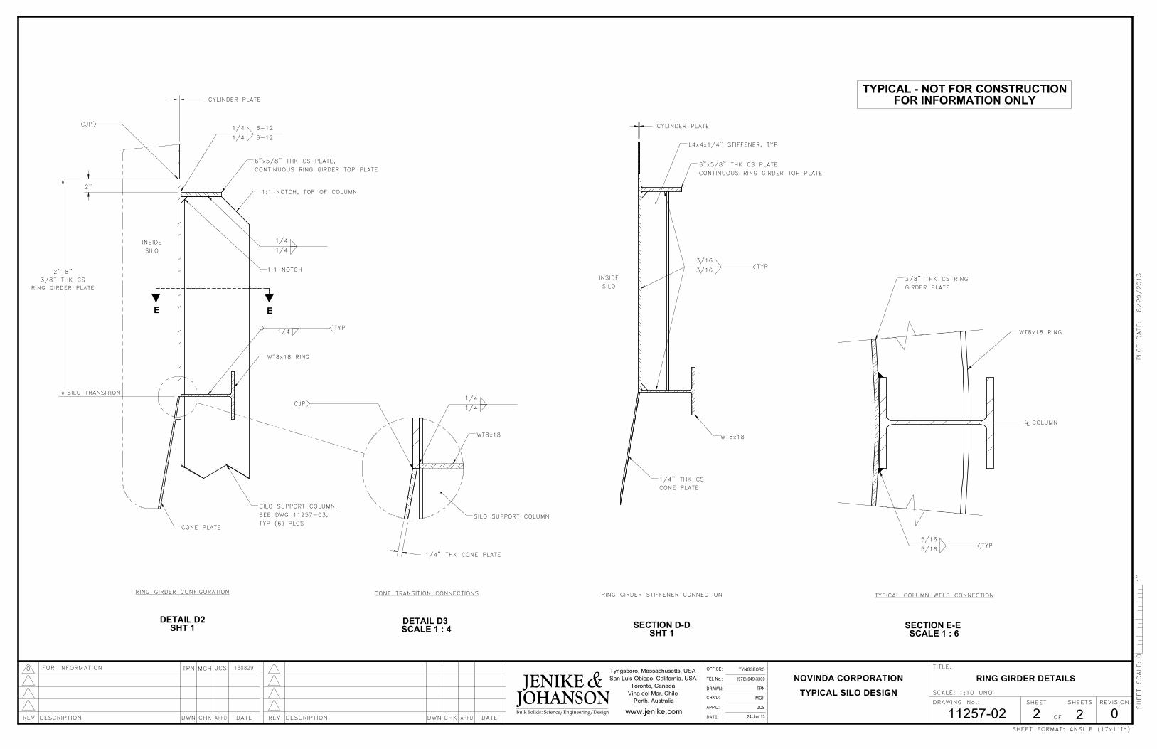
3/16
SHT 1SECTION D-D
CONE PLATE
WT8x18
1/4" THK CS
6"x5/8" THK CS PLATE,
RING GIRDER STIFFENER CONNECTION
CONTINUOUS RING GIRDER TOP PLATE
SILO
L4x4x1/4" STIFFENER, TYP
INSIDE
TYP3/16
CYLINDER PLATE
1/4
SCALE 1 : 4DETAIL D3
1/4
WT8x18
SILO SUPPORT COLUMN
CONE TRANSITION CONNECTIONS
CJP
1/4" THK CONE PLATE
1/4
SHT 1DETAIL D2
CONTINUOUS RING GIRDER TOP PLATE
SILO TRANSITION
1:1 NOTCH, TOP OF COLUMN
RING GIRDER CONFIGURATION
WT8x18 RING
6"x5/8" THK CS PLATE,
TYP (6) PLCS
1:1 NOTCH
SILO
SILO SUPPORT COLUMN,
INSIDE
CONE PLATE
1/4
SEE DWG 11257-03,
CJP6-12
1/4
1/4
6-12
1/4TYP
2'-8"
3/8" THK CS
RING GIRDER PLATE
2"
CYLINDER PLATE
E E
3/8" THK CS RING
GIRDER PLATE
CL
1 : 6SCALE E-E
TYPICAL COLUMN WELD CONNECTION
WT8x18 RING
SECTION
COLUMN
5/16
5/16TYP
11257-02 0
TYPICAL SILO DESIGN
NOVINDA CORPORATION
224 Jun 13
TPN
(978) 649-3300
TYNGSBORO
MGH
JCS
OF
DRAWING No.:
SCALE:
www.jenike.com
REVISION
TITLE:Tyngsboro, Massachusetts, USA
San Luis Obispo, California, USA
Toronto, Canada
Vina del Mar, Chile
Perth, Australia
SHEET FORMAT:
1:10 UNO
RING GIRDER DETAILS
TPN JCS0 MGHFOR INFORMATION
2
130829
SHEET SHEETS
DATEAPPDCHKDESCRIPTIONREV DWNDATECHK APPDDESCRIPTION DWNREV
TEL No.:
OFFICE:
APP'D:
DRAWN:
DATE:
CHK'D:
ANSI B (17x11in)
01"
SHEET SCALE:
PLOT DATE: 8/29/2013
JOHANSON Bulk Solids: Science/Engineering/Design
JENIKE &
TYPICAL - NOT FOR CONSTRUCTIONFOR INFORMATION ONLY
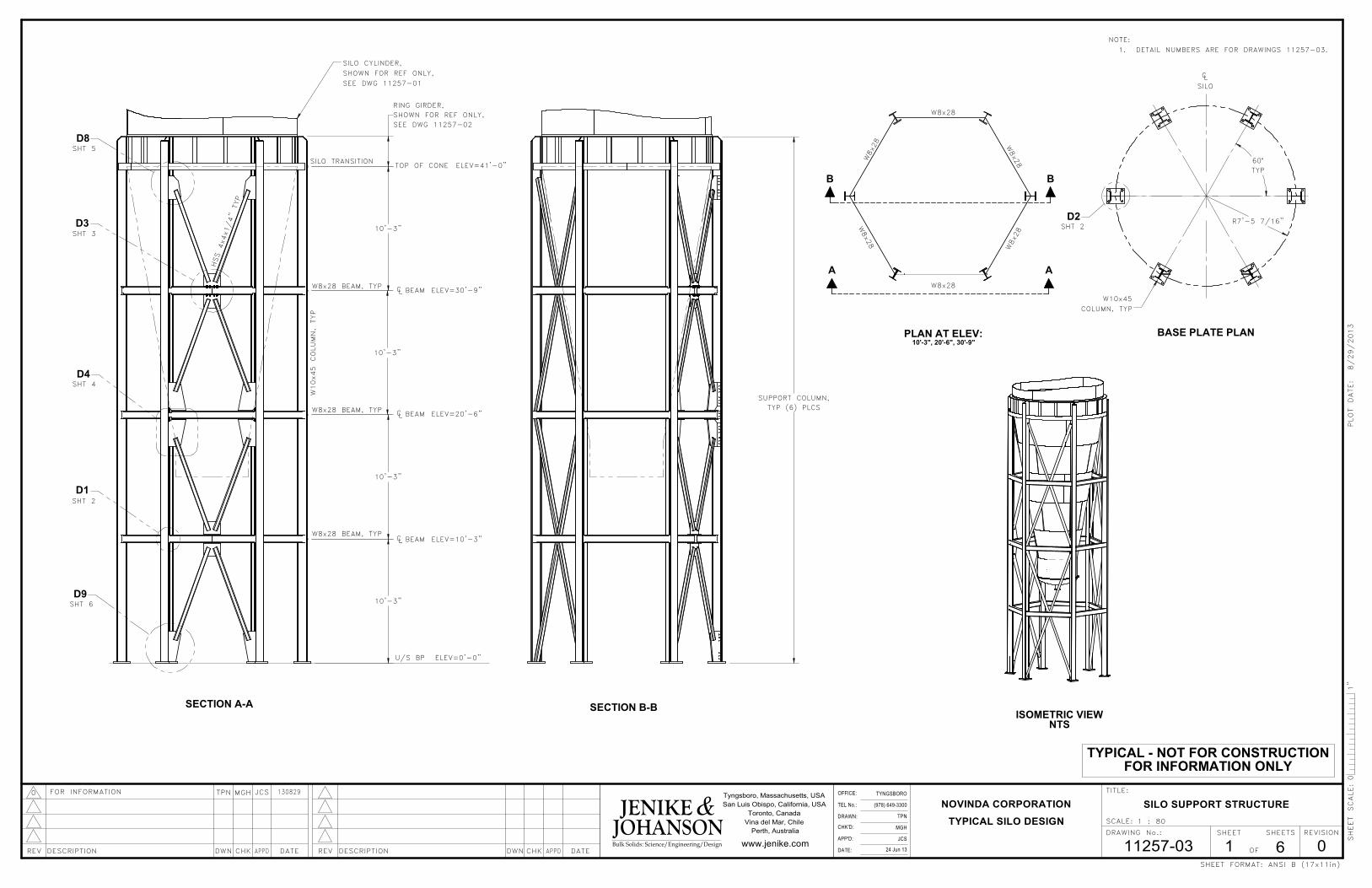
10'-3"
10'-3"
10'-3"
10'-3"
RING GIRDER,
SHOWN FOR REF ONLY,
SEE DWG 11257-02
R7'-5 7/16"
60°
TYP
TYNGSBORO
MGH
11257-03 0
(978) 649-3300
TPN
24 Jun 13 6
NOVINDA CORPORATION
TYPICAL SILO DESIGN
JCS
TITLE:
Perth, Australia
OF
DRAWING No.:
SCALE:
www.jenike.com
REVISION
Tyngsboro, Massachusetts, USA
San Luis Obispo, California, USA
Toronto, Canada
Vina del Mar, Chile
SHEET FORMAT:
130829
1 : 80
SILO SUPPORT STRUCTURE
TPN JCS0 MGHFOR INFORMATION
1JOHANSON Bulk Solids: Science/Engineering/Design
SHEET SHEETS
DATEAPPDCHKDESCRIPTIONREV DWNDATECHK APPDDESCRIPTION DWNREV
TEL No.:
OFFICE:
APP'D:
DRAWN:
DATE:
CHK'D:
ANSI B (17x11in)
01"
SHEET SCALE:
PLOT DATE: 8/29/2013
JENIKE &
ISOMETRIC VIEWNTS
SECTION B-B
SUPPORT COLUMN,
TYP (6) PLCS
D1
D8
D3
D4
D9
SECTION A-A
SHT 5
ELEV=0'-0"
SILO TRANSITION
HSS 4x4x1/4" TYP
W8x28 BEAM, TYP CL BEAM
BEAM
BEAM
TOP OF CONE
U/S BP
ELEV=10'-3"
ELEV=20'-6"
ELEV=30'-9"
W10x45 COLUMN, TYP
CL
CL
SHT 3
SHT 4
W8x28 BEAM, TYP
W8x28 BEAM, TYP
SHT 2
ELEV=41'-0"
SILO CYLINDER,
SHOWN FOR REF ONLY,
SEE DWG 11257-01
SHT 6
D2
SILO
CL
BASE PLATE PLAN
SHT 2
W10x45
COLUMN, TYP
NOTE:
1. DETAIL NUMBERS ARE FOR DRAWINGS 11257-03.
W8x28
W8x28
W8x28
W8x28
10'-3", 20'-6", 30'-9"
W8x28
PLAN AT ELEV:
W8x28
A A
BB
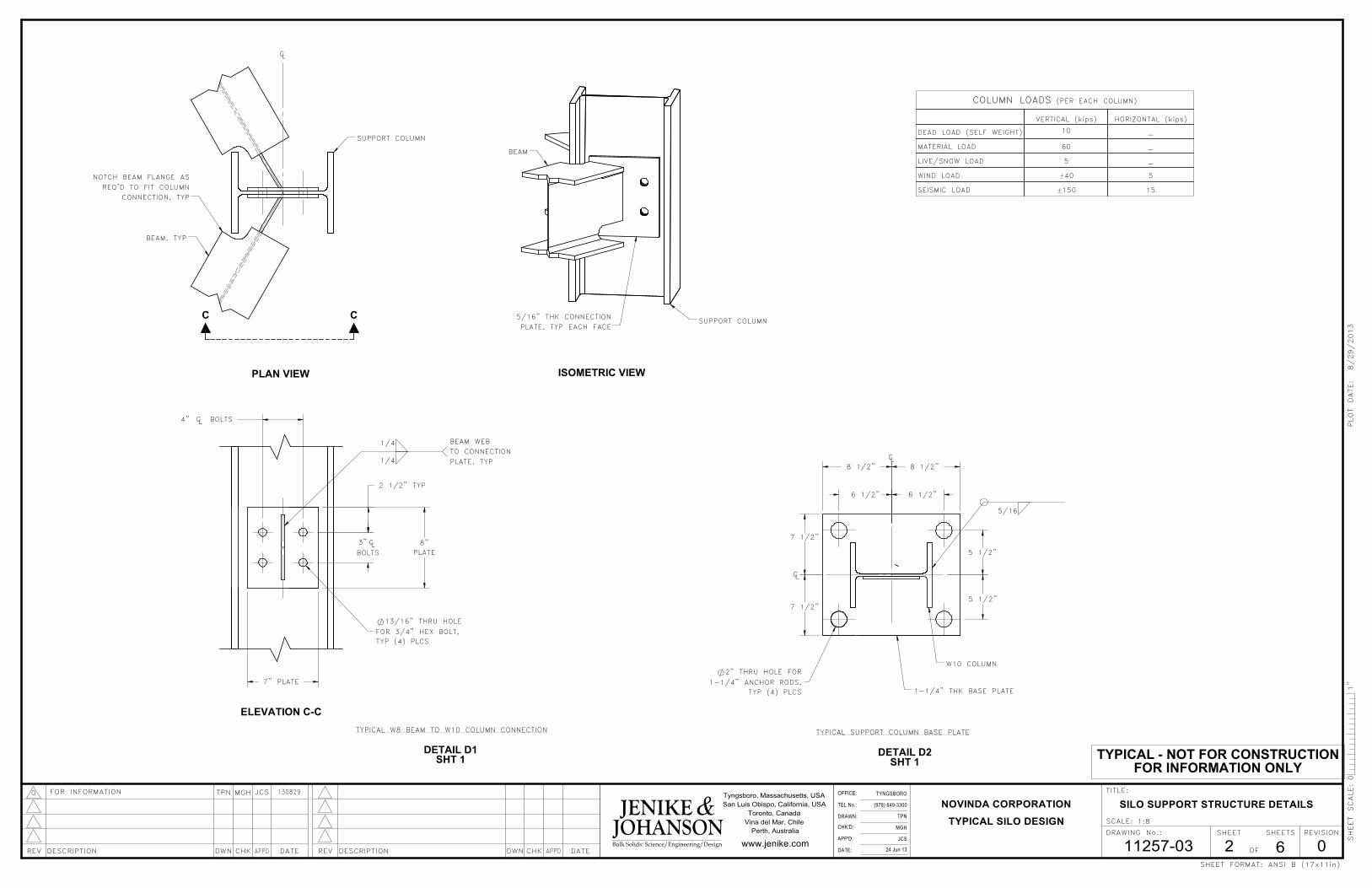
TYPICAL - NOT FOR CONSTRUCTIONFOR INFORMATION ONLY
7" PLATE
2" THRU HOLE FOR
1-1/4" ANCHOR RODS,
TYP (4) PLCS
TYPICAL W8 BEAM TO W10 COLUMN CONNECTION
SHT 1DETAIL D2
TYPICAL SUPPORT COLUMN BASE PLATE
COLUMN LOADS (PER EACH COLUMN)
VERTICAL (kips) HORIZONTAL (kips)
DEAD LOAD (SELF WEIGHT) 10-
MATERIAL LOAD 60 -
LIVE/SNOW LOAD 5 -
WIND LOAD 40 5
SEISMIC LOAD 150 15
MGH
11257-03
1:8
0
TYPICAL SILO DESIGN
TYNGSBORO
(978) 649-3300
TPN
24 Jun 13 6
NOVINDA CORPORATION
JCS
Perth, Australia
OF
DRAWING No.:
SCALE:
www.jenike.com
REVISION
TITLE:Tyngsboro, Massachusetts, USA
San Luis Obispo, California, USA
Toronto, Canada
Vina del Mar, Chile
SHEET FORMAT:
SILO SUPPORT STRUCTURE DETAILS
TPN JCS0 MGHFOR INFORMATION
2
130829
Bulk Solids: Science/Engineering/Design
SHEET SHEETS
DATEAPPDCHKDESCRIPTIONREV DWNDATECHK APPDDESCRIPTION DWNREV
TEL No.:
OFFICE:
APP'D:
DRAWN:
DATE:
CHK'D:
ANSI B (17x11in)
01"
SHEET SCALE:
PLOT DATE: 8/29/2013
JOHANSONJENIKE &
DETAIL D1
PLAN VIEW
SHT 1
SUPPORT COLUMN
BEAM, TYP
NOTCH BEAM FLANGE AS
REQ'D TO FIT COLUMN
CONNECTION, TYP
CL
CCSUPPORT COLUMN
PLATE, TYP EACH FACE
ISOMETRIC VIEW
5/16" THK CONNECTION
BEAM
ELEVATION C-C
1/4
1/4
BEAM WEB
TO CONNECTION
PLATE, TYP
CL3"
FOR 3/4" HEX BOLT,
BOLTSCL
8"
PLATEBOLTS
13/16" THRU HOLE
TYP (4) PLCS
4"
2 1/2" TYP
1-1/4" THK BASE PLATE
W10 COLUMN
CL
CL
5/16
7 1/2"
7 1/2"
6 1/2"
5 1/2"
5 1/2"
8 1/2" 8 1/2"
6 1/2"
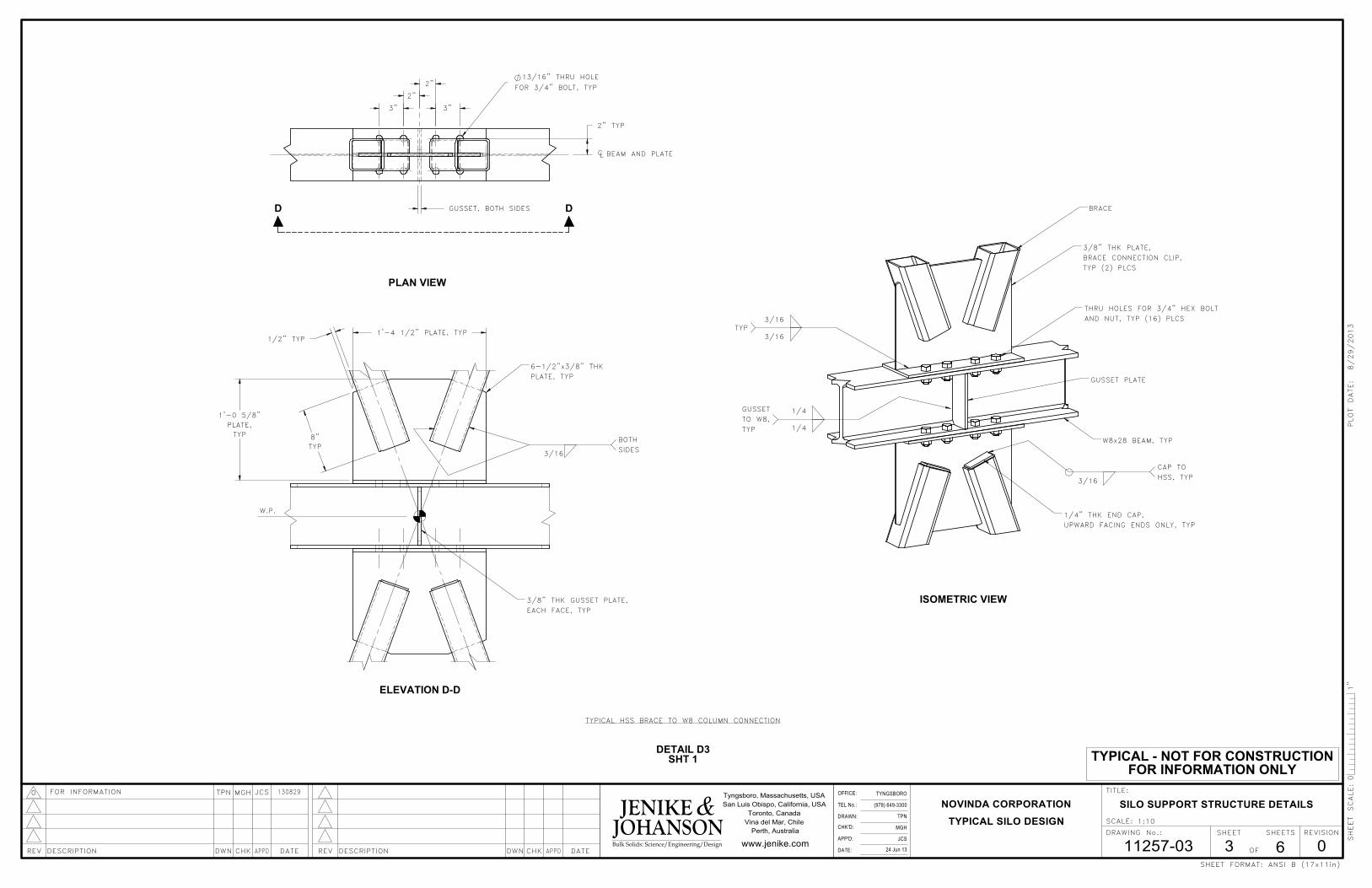
TYPICAL - NOT FOR CONSTRUCTIONFOR INFORMATION ONLY
DETAIL D3SHT 1
TYPICAL HSS BRACE TO W8 COLUMN CONNECTION
MGH
11257-03
1:10
0
TYPICAL SILO DESIGN
TYNGSBORO
(978) 649-3300
TPN
24 Jun 13 6
NOVINDA CORPORATION
JCS
Perth, Australia
OF
DRAWING No.:
SCALE:
www.jenike.com
REVISION
TITLE:Tyngsboro, Massachusetts, USA
San Luis Obispo, California, USA
Toronto, Canada
Vina del Mar, Chile
SHEET FORMAT:
SILO SUPPORT STRUCTURE DETAILS
TPN JCS0 MGHFOR INFORMATION
3
130829
Bulk Solids: Science/Engineering/Design
SHEET SHEETS
DATEAPPDCHKDESCRIPTIONREV DWNDATECHK APPDDESCRIPTION DWNREV
TEL No.:
OFFICE:
APP'D:
DRAWN:
DATE:
CHK'D:
ANSI B (17x11in)
01"
SHEET SCALE:
PLOT DATE: 8/29/2013
JOHANSONJENIKE &
PLAN VIEW
CL BEAM AND PLATE
2"
3"
FOR 3/4" BOLT, TYP
13/16" THRU HOLE
3"
2"
2" TYP
GUSSET, BOTH SIDES DD
SIDES
BOTH
EACH FACE, TYP
W.P.
PLATE, TYP
3/8" THK GUSSET PLATE,
3/16
ELEVATION D-D
6-1/2"x3/8" THK
1'-4 1/2" PLATE, TYP
TYP
8"TYP
PLATE,
1'-0 5/8"
1/2" TYP
TYP
HSS, TYP
TYP
1/4
ISOMETRIC VIEW
W8x28 BEAM, TYP
BRACE
3/16
3/8" THK PLATE,
3/16
GUSSET PLATE
1/4
TYP (2) PLCS
1/4" THK END CAP,
TO W8,
THRU HOLES FOR 3/4" HEX BOLT
AND NUT, TYP (16) PLCS
UPWARD FACING ENDS ONLY, TYP
GUSSET
BRACE CONNECTION CLIP,
3/16
CAP TO
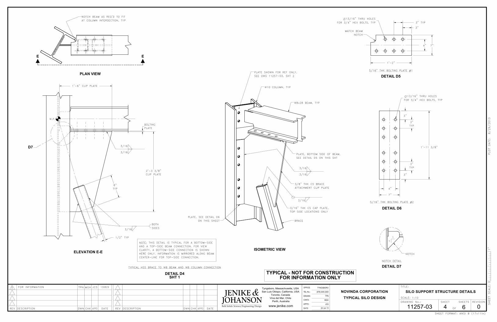
TYPICAL - NOT FOR CONSTRUCTIONFOR INFORMATION ONLYSHT 1
HERE ONLY. INFORMATION IS MIRRORED ALONG BEAM
3/16
THIS DETAIL IS TYPICAL FOR A BOTTOM-SIDE
DETAIL D4
CLARITY, A BOTTOM-SIDE CONNECTION IS SHOWN
W.P.
AND A TOP-SIDE BEAM CONNECTION. FOR VIEW
CENTER-LINE FOR TOP-SIDE CONNECTION.
TYPICAL HSS BRACE TO W8 BEAM AND W8 COLUMN CONNECTION
NOTE:
3/16
MGH
11257-03
1:10
0
TYPICAL SILO DESIGN
TYNGSBORO
(978) 649-3300
TPN
24 Jun 13 6
NOVINDA CORPORATION
JCS
Perth, Australia
OF
DRAWING No.:
SCALE:
www.jenike.com
REVISION
TITLE:Tyngsboro, Massachusetts, USA
San Luis Obispo, California, USA
Toronto, Canada
Vina del Mar, Chile
SHEET FORMAT:
SILO SUPPORT STRUCTURE DETAILS
TPN JCS0 MGHFOR INFORMATION
4
130829
Bulk Solids: Science/Engineering/Design
SHEET SHEETS
DATEAPPDCHKDESCRIPTIONREV DWNDATECHK APPDDESCRIPTION DWNREV
TEL No.:
OFFICE:
APP'D:
DRAWN:
DATE:
CHK'D:
ANSI B (17x11in)
01"
SHEET SCALE:
PLOT DATE: 8/29/2013
JOHANSONJENIKE &
PLATE, BOTTOM SIDE OF BEAM,
SEE DWG 11257-03, SHT 2
ISOMETRIC VIEW
ON THIS SHEET
3/16
ATTACHMENT CLIP PLATE
W10 COLUMN, TYP
PLATE, SEE DETAIL D6
BRACE
3/16" THK CS CAP PLATE,
TOP SIDE LOCATIONS ONLY
W8x28 BEAM, TYP
3/8" THK CS BRACE
SEE DETAIL D5 ON THIS SHT
PLATE SHOWN FOR REF ONLY,PLAN VIEW
NOTCH BEAM AS REQ'D TO FIT
AT COLUMN INTERSECTION, TYP
EE
5/16" THK BOLTING PLATE #1
DETAIL D5
MATCH BEAM
NOTCH
4"
3"
3" TYP
1'-2"
7"
13/16" THRU HOLES
FOR 3/4" HEX BOLTS, TYP
5/16" THK BOLTING PLATE #2
DETAIL D6
3"
3"
TYP
1'-11 3/8"
3"
TYP
7"
4"
3"
13/16" THRU HOLES
FOR 3/4" HEX BOLTS, TYP
D7
ELEVATION E-E
SIDES
3/16
3/16
BOTH
3/16
TYP
1'-6" CLIP PLATE
2'-3 3/8"
8"
PLATE
CLIP PLATE
BOLTING
1/2" TYP
DETAIL D7
1
1
NOTCH
NOTCH DETAIL
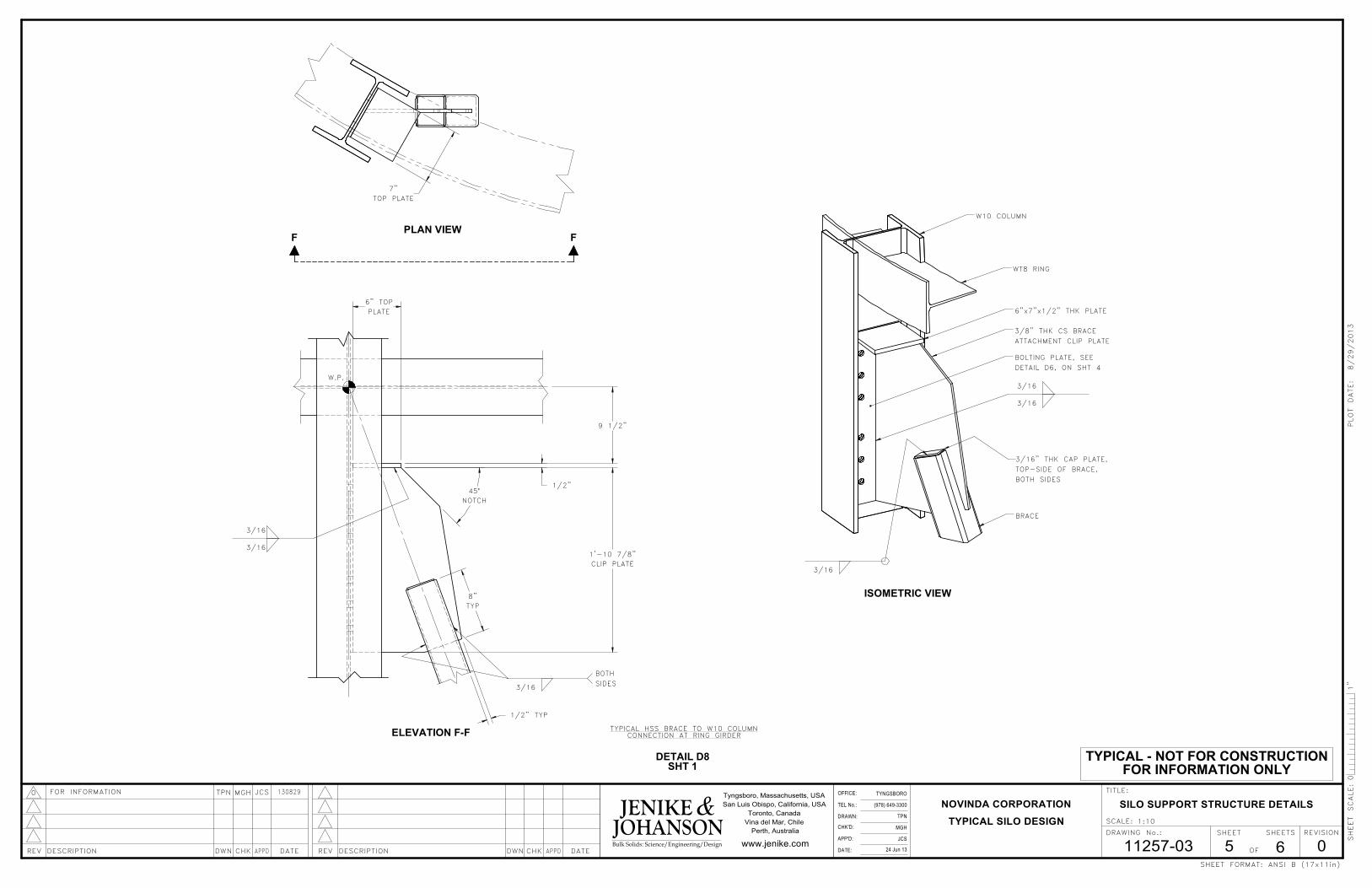
9 1/2"
TYPICAL - NOT FOR CONSTRUCTIONFOR INFORMATION ONLY
PLAN VIEW
7"
TOP PLATE
F F
BOTH
W.P.
SIDES
3/16
ELEVATION F-F
3/16
3/16
NOTCH
45°
1/2" TYP
CLIP PLATE
1'-10 7/8"
1/2"
6" TOP
PLATE
8"
TYP
DETAIL D8SHT 1
TYPICAL HSS BRACE TO W10 COLUMNCONNECTION AT RING GIRDER
MGH
11257-03
1:10
0
TYPICAL SILO DESIGN
TYNGSBORO
(978) 649-3300
TPN
24 Jun 13 6
NOVINDA CORPORATION
JCS
Perth, Australia
OF
DRAWING No.:
SCALE:
www.jenike.com
REVISION
TITLE:Tyngsboro, Massachusetts, USA
San Luis Obispo, California, USA
Toronto, Canada
Vina del Mar, Chile
SHEET FORMAT:
SILO SUPPORT STRUCTURE DETAILS
TPN JCS0 MGHFOR INFORMATION
5
130829
Bulk Solids: Science/Engineering/Design
SHEET SHEETS
DATEAPPDCHKDESCRIPTIONREV DWNDATECHK APPDDESCRIPTION DWNREV
TEL No.:
OFFICE:
APP'D:
DRAWN:
DATE:
CHK'D:
ANSI B (17x11in)
01"
SHEET SCALE:
PLOT DATE: 8/29/2013
JOHANSONJENIKE &
BOLTING PLATE, SEE
DETAIL D6, ON SHT 4
ATTACHMENT CLIP PLATE
3/8" THK CS BRACE
3/16
3/16
3/16
WT8 RING
ISOMETRIC VIEW
W10 COLUMN
6"x7"x1/2" THK PLATE
TOP-SIDE OF BRACE,
3/16" THK CAP PLATE,
BRACE
BOTH SIDES

TYPICAL - NOT FOR CONSTRUCTIONFOR INFORMATION ONLY
MGH
11257-03
1:10
0
TYPICAL SILO DESIGN
TYNGSBORO
(978) 649-3300
TPN
24 Jun 13 6
NOVINDA CORPORATION
JCS
Perth, Australia
OF
DRAWING No.:
SCALE:
www.jenike.com
REVISION
TITLE:Tyngsboro, Massachusetts, USA
San Luis Obispo, California, USA
Toronto, Canada
Vina del Mar, Chile
SHEET FORMAT:
SILO SUPPORT STRUCTURE DETAILS
TPN JCS0 MGHFOR INFORMATION
6
130829
Bulk Solids: Science/Engineering/Design
SHEET SHEETS
DATEAPPDCHKDESCRIPTIONREV DWNDATECHK APPDDESCRIPTION DWNREV
TEL No.:
OFFICE:
APP'D:
DRAWN:
DATE:
CHK'D:
ANSI B (17x11in)
01"
SHEET SCALE:
PLOT DATE: 8/29/2013
JOHANSONJENIKE &
3/8" THK BRACE
COLUMN BASE PLATE,
ATTACHMENT CLIP PLATE
BOLTING PLATE, SEE
SEE DETAIL D2, ON SHT 2
DETAIL D10, ON THIS SHT
W10 COLUMN
3/16
3/16
3/16
BRACE
ISOMETRIC VIEW
3/16
PLAN VIEW
GG
ELEVATION G-G
W.P.
SIDES
BOTH
3/16
2'-6"
CLIP PLATE
8"
1/2" TYP
DETAIL D10
5/16" THK BOLTING PLATE #3
3"
3"
TYP
TYP
13/16" THRU HOLES
FOR 3/4" HEX BOLTS, TYP
3"
7"
2'-6"
3"
4"
SHT 1DETAIL D9
TYPICAL HSS BRACE TO W10 COLUMNCONNECTION AT BASE PLATE
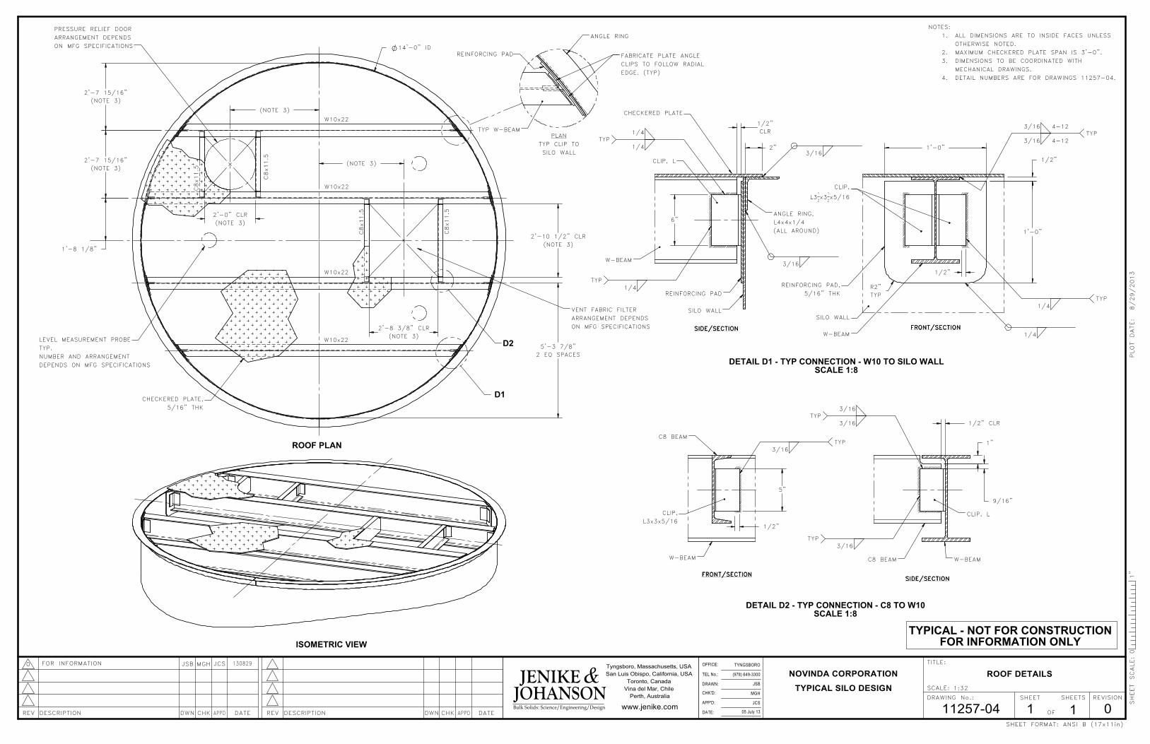
2'-7 15/16"
(NOTE 3)
5'-3 7/8"
2 EQ SPACES
TYPICAL - NOT FOR CONSTRUCTION
FOR INFORMATION ONLY
1/2"
1/2"
CHECKERED PLATE
NOTES:
ALL DIMENSIONS ARE TO INSIDE FACES UNLESS 1.
OTHERWISE NOTED.
MAXIMUM CHECKERED PLATE SPAN IS 3'-0".2.
DIMENSIONS TO BE COORDINATED WITH3.
MECHANICAL DRAWINGS.
DETAIL NUMBERS ARE FOR DRAWINGS 11257-04.4.
(978) 649-3300
TYNGSBORO
MGH
11257-04
JSB
05 July 13 1
NOVINDA CORPORATION
TYPICAL SILO DESIGN
0JCS
REVISION
TITLE:
Perth, Australia
OF
DRAWING No.:
SCALE:
www.jenike.com
Tyngsboro, Massachusetts, USA
San Luis Obispo, California, USA
Toronto, Canada
Vina del Mar, Chile
SHEET FORMAT:
130829
1:32
ROOF DETAILS
JSB JCS0 MGHFOR INFORMATION
1
SHEET SCALE:
PLOT DATE: 8/29/2013
JOHANSON Bulk Solids: Science/Engineering/Design
SHEET SHEETS
DATEAPPDCHKDESCRIPTIONREV DWNDATECHK APPDDESCRIPTION DWNREV
TEL No.:
OFFICE:
APP'D:
DRAWN:
DATE:
CHK'D:
ANSI B (17x11in)
01"
JENIKE &
ISOMETRIC VIEW
D2W10x22
5/16" THK
W10x22
C8x11.5
DEPENDS ON MFG SPECIFICATIONS
C8x11.5
W10x22
CHECKERED PLATE,
W10x22
C8x11.5
NUMBER AND ARRANGEMENT
D1
TYP.
ROOF PLANC8x11.5
LEVEL MEASUREMENT PROBE
PRESSURE RELIEF DOOR
ARRANGEMENT DEPENDS
ON MFG SPECIFICATIONS
2'-7 15/16"
(NOTE 3)
1'-8 1/8"
2'-10 1/2" CLR
(NOTE 3) (NOTE 3)
(NOTE 3)
(NOTE 3)
2'-8 3/8" CLR
(NOTE 3)
2'-0" CLR
14'-0" ID
VENT FABRIC FILTER
ARRANGEMENT DEPENDS
ON MFG SPECIFICATIONS
PLAN
SILO WALL
ANGLE RING
REINFORCING PAD
TYP CLIP TO
FABRICATE PLATE ANGLE
CLIPS TO FOLLOW RADIAL
EDGE. (TYP)
TYP W-BEAM
FRONT/SECTIONFRONT/SECTIONFRONT/SECTIONFRONT/SECTION
5/16" THK
2
1
TYP
W-BEAM
TYP
REINFORCING PAD,
1/4
3/16
x5/16
4-12
SILO WALL
4-12
CLIP,
L31
2x3
3/16
1/4
1'-0"
1/2"
1'-0"
R2"
TYP
W-BEAM
1/4TYP
SILO WALL
1/4
3/16
DETAIL D1 - TYP CONNECTION - W10 TO SILO WALL
SCALE 1:8
(ALL AROUND)
3/16
SIDE/SECTIONSIDE/SECTIONSIDE/SECTIONSIDE/SECTION
CLIP, L
REINFORCING PAD
L4x4x1/4
ANGLE RING,
1/4TYP
CLR
6"
1/2"
2"
SCALE 1:8
L3x3x5/16
FRONT/SECTIONFRONT/SECTIONFRONT/SECTIONFRONT/SECTION
CLIP,
DETAIL D2 - TYP CONNECTION - C8 TO W10
C8 BEAM
W-BEAM
3/16TYP
5"
C8 BEAM
TYP
SIDE/SECTIONSIDE/SECTIONSIDE/SECTIONSIDE/SECTION
3/16
W-BEAM
CLIP, L
3/16
3/16TYP
1"
9/16"
1/2" CLR