Embed Size (px)
Citation preview


1
CONTENT
CONTENT .................................................................................................................... 1
INTRODUCTION ......................................................................................................... 5
1. AQUEOUS SOLUTIONS OF HIGH MODULUS SILICATE SYSTEMS........... 11
1.1. Liquid Glass ..................................................................................................... 11
1.2. Alkali Metal Polysilicates ................................................................................ 13
1.3. Colloidal Solutions - Silica Sols ...................................................................... 15
1.4. Metal Alkoxides ............................................................................................... 20
1.5. Metal organic siloxanes - Intermediate Products between ChemicalCompounds and Nanocomposites ................................................................... 27
2. SOL-GEL TECHNOLOGY .................................................................................... 37
2.1. Alkoxide Method of Sol-Gel Synthesis ........................................................... 38
2.2. Non-Hydrolytic Method of Sol-Gel Synthesis ................................................. 48
2.3. Colloidal Method of Sol-Gel Synthesis ........................................................... 50
2.4. Soluble Silicates as Precursors are in the Sol-Gel Technology ofNanocomposites .............................................................................................. 52
2.5. Preparation of Nanocomposites Through Aerogels ......................................... 54
3. HARDENING SYSTEMS ON THE BASIS OF LIQUID GLASS AND WATERSOLUTIONS OF SILICATES ....................................................................... 61
3.1. Hardening at Normal Temperatures by Removing Moisture .......................... 61
3.2. Hardening of Liquid Glass Using Reagents ..................................................... 64
3.3. Silica Sol Gelation ............................................................................................ 67
3.4. Influence of Characteristics of Silica Sol on the Properties of the ResultingXerogels .......................................................................................................... 73
4. SIMULATION OF HARDENING PROCESSES, IN SILICATE SYSTEMS ...... 75
4.1. Quasi-homogeneous Approximation to Describe the Properties of DisperseSystems ............................................................................................................ 75
4.2. Statistical Polymer Method. Main Notions, Definitions and Equations .......... 77
2
4.3. Crosslink Formation ......................................................................................... 80
4.4. Thermodynamic Functions of Non-Crosslinked Statistical Polimers. Non-Equilibrium ...................................................................................................... 82
4.5. Combination of the Statistical Polymer and Fractal Methods ......................... 83
4.6. Description of the State of Colloidal Solutions of Silicon Oxide from theViewpoint of Statistical Physics. .................................................................... 86
4.7. Analysis of the Behavior of Silica Sol, in Terms of Maxwell-BoltzmannDistribution ...................................................................................................... 92
4.8. The Mean Free Path of the Colloidal Particles ................................................ 99
4.9. Basic Approaches to Modeling of the Sol-Gel Transition Kinetics .............. 111
4.10. Formal Kinetic Description of the Sol-Gel Process ..................................... 120
5. DIFFERENT TYPES OF NANOPHASES .......................................................... 127
5.1. Nano-Sized Filler ........................................................................................... 127
5.2. Nano-Sized Binder ......................................................................................... 134
5.3. Synthesis of Nano-Phase in the Matrix of the Composite Structure ............. 139
6. INFLUENCE OF VARIOUS FACTORS ON STRUCTURE AND PROPERTIESOF HYBRID MATERIALS ......................................................................... 143
6.1. Packing of Spherical Nanoparticles of the Filler ........................................... 143
6.2. Packing of Fibrous Nanoparticles of the Filler .............................................. 151
6.3. Nanomaterials Based on Layered Particles .................................................... 156
6.4. Mixing Technologies of Nanocomposites ..................................................... 159
6.5. Fractal and Hierarchical Structure of Nanostructured Composite Materials . 162
6.6. Properties of Nanostructured Agents ............................................................. 169
7. PERSPECTIVE DIRECTIONS OF APPLICATION OF LIQUID GLASS ANDWATER SOLUTIONS OF HIGH MODULUS OF SILICATES INCONSTRUCTION AND INDUSTRY ......................................................... 177
7.1. The Use of Liquid Glass and Water Solutions of Silicates in the Rocket-SpaceTechnology .................................................................................................... 177
7.2. Materials based on quaternary ammonium silicates ...................................... 180
7.3. Nanostructured Silicate Polymer Concrete .................................................... 181
7.4. Deposition of Protective Coatings on the Surface ......................................... 188
3
7.5. Silicate Nanomiaterials Coatings for Protection of Monuments of History, Architecture and cultural heritage ................................................................. 193
7.6. Application of Sols to Obtain Inorganic Composites and Ceramics ............. 197
7.7. Obtaining Monolithic Blocks of Silica .......................................................... 199
7.8. Production of Thin Films ............................................................................... 202
7.9. Refractory Ultra-Lightweight Materials ........................................................ 204
7.9.1. Application of Silica as a Binder Prepared by Chemical Vapor Depositionof Sodium Silicates .............................................................................................. 204
7.9.2. Application of Silica Sol as a Binder ........................................................ 206
7.10. Production of Acid-Resistant Materials and Linings ................................... 211
7.11. Biological synthesis of multifunctional inorganic and bio-organic hybridmaterials ........................................................................................................ 212
CONCLUSION ......................................................................................................... 217
REFERENCES .......................................................................................................... 219

4
5
INTRODUCTION
Development of humankind since the ancient times was associated with the useof natural and then synthetic composite materials. The first instruments of labor thatwere used by people have been made from wood - lignin polymer, which wasreinforced with fiber and from bone - a composite consisting of inorganicmicrocrystals and protein polymer. Later it was found that, flint and nephrite - mostsolid from all varieties of stones encountered by people in nature. So nephrite iscomposed of tangled masses of fibrous crystals [1]. Flint is composed ofmicrocrystalline quartz [2], and its crystals have a size less than 100 nm and linkedtogether by amorphous silica. Also, agate, which is a relative of quartz ismicrocrystalline quartz containing rod-like crystals of cristobalite. Flint has a tensilestrength of 207 MPa, and nephrite - 275 MPa [3]. These materials were ancientprototypes of modern reinforced plastics, composites, and, in fact, were thenanocomposite materials.
The composite material, the composite – is inhomogeneous solid materialconsisting of two or more components with a clear boundary between them, which iscreated artificially. Most composites (except layered) components can be divided intoa matrix or binder, and included in it reinforcing elements or fillers. In compositesconstructional purposes, reinforcing elements normally provide the necessarymechanical characteristics of the material (strength, stiffness etc.), and the matrix, inturn, enables collaboration reinforcing elements, and protecting them frommechanical damage and corrosive chemical environment. Also, composites are calledmulti-component systems which consist of a polymer, metal, carbon, ceramic or othersubstrate (matrix) reinforced with fillers of fibers, whiskers, particles, etc. [4,5]. Theuse of composite materials in various engineering applications has become almost anart.
Inorganic non-metallic materials such as glass or ceramics, people receivethousands of years from the solids using high temperatures. As raw materials, naturalminerals used and the processing of these materials usually includes shredded of solidraw materials, and sintering a mixture thereof at temperatures exceeding 700 . Inparticular, oxide ceramics and glass have attracted attention in the last century due to
6
their thermal longevity and chemical inertness. They are generally is obtained fromoxide minerals, by mixing with different additives to obtain specified compositions. High temperatures are usually necessary for carrying out of these solid-statereactions. This is due to the fact that the feedstock used in the form of powders, andthey react in the solid state or in the melt to form the final product. Product formationin the solid state is possible only if ionic components of reagents diffuse through thegrains of material. For this purpose they have to overcome the relatively high bindingforces in crystals, and this requires an increase in temperature. Many modernelectronic and optical devices require special forms or application proceduresbonding of ceramic parts, and it is inadmissible to use of high-temperature treatment. Furthermore, for some ceramic products is not available application of powdertechnology, for example, of thin oxide films. Therefore, classic solid reactions havethe following disadvantages:
• High temperatures and long reaction time associated with the necessity of ionsmovement through the solid phase or the formation of melts,
• The reaction conditions and product quality are largely dependent on theconditions of raw material preparation (grinding, pressing, etc.),
• Specific morphology, in many cases not available through classical techniques(thin films, porous materials, etc.)
• A combination of organic or biological materials is impossible due to theextreme conditions of materials manufacture.
These problems have been solved with the use of composite materials. A specialplace in this group of materials is occupied by nanomaterials and nanocomposites [5].
Nanomaterials - materials made by using nanoparticles and / or by means ofnanotechnology, and have some unique properties due to the presence of theseparticles in the material. To nanomaterials belong objects that have one of the typicaldimensions is between 1 and 100 nm [6]. There are two basic ways to create ofnanoobjects:
1. Reduce the size of macroscopic objects (dispersing, disintegrating, grinding tothe cluster level using a ball mills or using the mechanochemical synthesis);
2. Creating nanostructures from atoms and molecules (crystallization) clustering, nanostructuring, nucleation, condensation, coagulation, polymerization, etc.
In the group of nano-materials are the following types:• Nanoporous structure;• Nanoparticles;• Nanotubes and nanofibers;• Nanodispersions (colloids);• Nanostructured surfaces and films;• Nanocrystals and nanoclusters;
7
• Nanocomposites. Nanocomposite - multicomponent material consisting of a base (matrix) and
filler - nanomaterial surface modified and having a new and improved complex ofproperties. In some cases there may be an inversion nanodimension at the binder andfiller.
Nanomaterials themselves are divided on the appointment to the: functional, compositional, and constructional.
By the number of measurements, they are divided into:• Zero-dimensional / quasi-zero-dimensional (quantum dots, spheroid
nanoparticles);• One-dimensional / quasi-one-dimensional (quantum wires, nanotubes);• Two-dimensional / quasi-two-dimensional (thin films, phase boundary);• Three-dimensional / quasi-three-dimensional (multilayer structures with
nanoscale dislocations, superlattices, nanoclusters, nanocomposites, supramolecularcompounds).
Properties of nanomaterials are usually differing from similar materials in thebulk state. For example, nanomaterials may be observed change of the optical, magnetic, thermal and conductive properties. For very fine materials can observe thechange in melting temperature towards its reduction.
In this review, we discuss a particular group of nanocomposites - organic-hybridcomposites. In practice, the nanocomposite materials contain reinforcing elementswith an extremely high specific surface area, immersed, for example, in a polymermatrix. In this case, the organic and inorganic components form independent phases, so the contact is achieved at the phase boundary. [7]
Promising modern composite materials are those in which the organic andinorganic components interact at the molecular level. They were called "polymerhybrids" [8,9]; the concept of "hybrid" was made in order to emphasize the nature ofthe molecular interaction between the components.
Hybrid materials - materials produced due to the interaction of components withdifferent chemical properties. Most often it is the organic and inorganic substanceswhich form a certain spatial structure. These structures differ from that of the initialreagents, but often inherit certain motives and functions of the original structures.
Feature of the new composite materials is the fact that they have nanometerparameters of their structural elements. The size of at least one of the directions is notmore than 100 nm. This is either nanometer distances between the lattices and thelayers which formed by polymer and inorganic ingredients or nanometer size formedof particles including particles containing metals [10].
As inorganic compounds - precursor - typically used: oxides of silicon, aluminum, titanium, zirconium, vanadium, molybdenum, clays, layered silicates and
8
zeolites, phosphates, and metal chalcogenides, iron oxychloride, graphite, variousmetals, etc. As the polymer component used carbochain and organometallicpolymers, usually silicone polymers.
From an environmental point of view are optimal drainless methods of obtainingcomposite materials, in particular, sol-gel or spin-on-glass process. This method isallows to exclude multiple washing steps, as used as starting material a compoundwithout introducing impurities into the final product composition [11].
Sol - a colloidal dispersion of solid particles in a liquid. Colloids - this is asuspension in which the dispersed phase is so small (1÷1000 nm), that thegravitational forces may be neglected. Here are dominant short-range forces, such asvan der Waals, and also the Coulomb forces, attraction and repulsion between thesurface charges. The inertia of the dispersed phase is small, so there is a Brownianmotion of the particles (Brownian diffusion), ie random jumps caused by the kineticenergy imparted by the collision of the sol particles with each other and with themolecules of the dispersion medium. The important factor is that the dispersedparticles are not molecules that are aggregates consisting of a plurality of molecules[13].
Colloidal gel formation occurs by a different mechanism. The particles of thedispersed phase (micelles) under the influence of attraction dispersion forces interactwith each other to form a skeleton of the inorganic polymer.
The gel obtained from a polymeric sol formed during polymerization of themonomers and the polymers are in sol. In this process, gradually from polymerizablebranched oligomers is formed a gigantic cluster. When the cluster reachesmacroscopic size and will spread to the entire volume of the sol, said that there was asol-gel transition. In this case, the gel will comprise, on the one hand, of a continuousstructural grid - solid skeleton (core) and on the other - of a continuous liquid phase.
The gel comprises continuous solid and fluid phases which are of colloidal size(from 1 to 1000 nm) [12]. These phases are continuous interpenetrating systems.
Are currently researchers published a large number of reviews devoted to theobtaining, investigation of the properties and the use of nanocomposite materials. Inmany monographs and individual chapters are devoted to the topic ofnanocomposites.
However, as noted by Y.D. Tretyakov [13], the researchers still no consensus onthe understanding that relates to the concept of nanomaterials and nanotechnology. So, recently published monograph Guglielmi M., Kickelbick G., and Martucci A. «The sol-gel + Nanocomposites" [11] is devoted to a fairly narrow range of alkoxidetechnology of nanocomposite materials. In the present work we would like tohighlight a separate area of nanocomposite materials - hybrid nanocomposites, and, inparticular, a separate area of these materials based on silicate systems. In this area,
9
too, there is no coherent and common understanding of terms and concepts. In theliterature often uses the term organic-inorganic hybrids. On one hand, this term is toogeneral and does not give understand the essence of the phenomenon. Thus, atpresent to inorganic chemistry attributed such broad field of chemistry, chemistry ofcomplex chemical compounds with organic ligands, or chemistry of metalcarboxylate compounds and alkoxides chemistry of chemical elements. All thesecompounds fall under the category of organic-inorganic hybrids. But thosecompounds are not composite materials, although widely used in the preparationthereof. Main distinguishing feature of the composite material, from, albeitcomplicated, but still a chemical compound is the presence of the interface betweenthe phases that are part of the material. Thus, for nanocomposites, at least one of thelinear dimensions of these phases should are in the range of nanometers. As anexample, when considering the general laws we chose a class of materialsexceptionally on the basis of silicate systems, because it is a typical representative ofextensive class of nanomaterials. Furthermore, in the present work are reflected, andsummarized results of investigations conducted by the authors during many years insilicate systems, and independently of each other.

10
11
1. AQUEOUS SOLUTIONS OF HIGH MODULUSSILICATE SYSTEMS
1.1. Liquid Glass
The term "liquid glass" is very broad and includes the aqueous solutions ofalkali silicates, regardless of the kind of cation, the concentration of silica, polymerstructure and its method for preparation of such solutions. Thus, in addition todissolving the water-soluble glasses, the liquid glass was obtained by dissolving silicain alkalis, but also by dissolving amorphous or crystalline powders, hydrated oranhydrous alkali silicates. Liquid glass can be potassium, sodium, lithium, andquaternary ammonium, or other strong organic bases. A region of compositions ofliquid glasses covers a wide variety. They start with a highly alkaline systems, andhighly siliceous polysilicate solutions, and end in the stabilized silica sols.
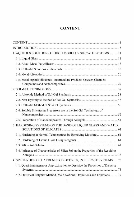
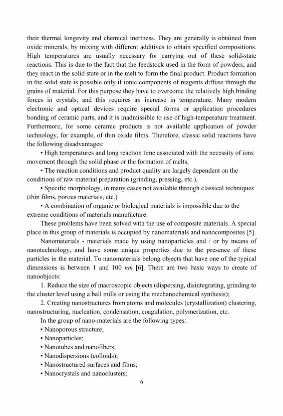
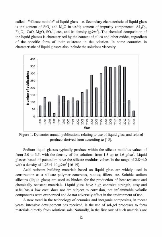
As water soluble glass and liquid glass are large-products of organic synthesisand produced in all industrialized countries. Interest to these technical products hasincreased significantly in recent years. It detects a wide range of valuable properties, environmental friendliness of their production and use, non-flammability and non-toxicity, and in many cases the cheapness and availability of raw materials. Figure 1shows the changes in the number of publications devoted to the application of liquidglass and related products in various technological processes of different materials[15]. In recent years, the number of publications devoted to the water glassmonotonically increased to about 2005, and now has reached a certain level of stableand varies in the range 315 ± 36 publications per year.
Soluble glass (soluble sodium and potassium silicates) is a substances in anamorphous glassy state, characterized by a certain content of — 2 and SiO2, where — is Na and . SiO2/M2O molar ratio is 2.6 ÷ 3.5 when the content of SiO2
69 ÷ 76 wt. % of sodium water glass and 65 ÷ 69 wt. % - for potassium glass. Liquid glass can be subdivided by type of alkali cations on the sodium,
potassium, lithium, organic bases. By mass or molar ratio in the glass: SiO2 and M2O, where M - is K, Na, Li, or an organic base. In this case, the molar ratio SiO2/M2O
12
called - "silicate module" of liquid glass – n. Secondary characteristic of liquid glassis the content of SiO2 and M2O in wt.%; content of impurity components: A12O3, Fe2O3, CaO, MgO, SO4
2-, etc., and its density (g/cm3). The chemical composition ofthe liquid glasses is characterized by the content of silica and other oxides, regardlessof the specific form of their existence in the solution. In some countries incharacteristic of liquid glasses also include the solutions viscosity.
Figure 1. Dynamics annual publications relating to use of liquid glass and relatedproducts derived from according to [15].
Sodium liquid glasses typically produce within the silicate modulus values offrom 2.0 to 3.5, with the density of the solutions from 1.3 up to 1.6 g/cm3. Liquidglasses based of potassium have the silicate modulus values in the range of 2.8÷4.0with a density of 1.25÷1.40 g/cm3 [16-19].
Acid resistant building materials based on liquid glass are widely used inconstruction as a silicate polymer concretes, putties, fillers, etc. Soluble sodiumsilicates (liquid glass) are used as binders for the production of heat-resistant andchemically resistant materials. Liquid glass have high cohesive strength, easy andsafe, has a low cost, does not are subject to corrosion, not inflammable volatilecomponents were evaporated and do not adversely affect in the environment of use.
A new trend in the technology of ceramics and inorganic composites, in recentyears, intensive development has received, is the use of sol-gel processes to formmaterials directly from solutions sols. Naturally, in the first row of such materials are
13
the products based on the silica sol, which in this case are a continuation of a numberof liquid glasses while striving to infinity silicate module [20].
Practical use of liquid glasses is realized in the following directions. The firstdirection is the manifestation in the liquid glass binding properties - the ability toself-hardening to form an artificial of silicate rock. The unique ability of the liquidglass is its high adhesive properties to substrates of different chemical nature. In thesecases, the liquid glass acting as a binder for a chemical gluing different materials usedin coatings and production of the composite materials of wide application.
The second direction involves the use of liquid glasses as a soluble source ofsilica, i.e. raw source component for the synthesis of various siliceous materials - ofsilica gel, white carbon, zeolites, catalysts and carriers for them, silica sol, etc.
The third area relates to the use of alkali metal silicates, as chemical componentsin various substances. This direction provides for the use liquid glass in themanufacture of synthetic detergents, for bleaching and cloth dying, in papermaking, etc.
1.2. Alkali Metal Polysilicates
Liquid Glass - alkaline solutions of sodium and potassium silicates arerepresentatives of a wider class of water-soluble silicates and liquid glasses producedon an industrial scale. The group of water-soluble silicates includes crystallineanhydrous sodium and potassium silicates, and crystalline and amorphous sodiumand potassium hydrosilicates in the form of powders, etc. Amorphous powdershydrosilicates of alkali metals [21], characterized by compositions within theSiO2/M2O = 2÷3.5, when the content of bound water is 15 ÷ 20%. Such powders areusually obtained by spray drying the concentrated liquid glasses and high hydrationof glassy silicates. They are loose, quickly dissolved in hot and cold water. Crystalline hydrosilicates manufacturing, usually represented crystalline hydratedisubstituted sodium orthosilicate Na2H2SiO4, containing from 4 to 9 molecules ofcrystalline hydrate water. This is also known as hydrated metasilicate formulasNa2O•SiO2•5H2O and Na2O•SiO2•9H2O.
The above products - liquid glass, glassy silicates, hydro silicates in crystallineand amorphous state - are so-called low-modulus silicates with a molar ratioSiO2/M2O=l÷4. The need to improve certain properties of composite materials basedon them, such as water resistance and thermal properties have led to the developmentof "high-modulus liquid glass" - polysilicates of alkali metals. Polysilicates groupincludes alkali metal silicates (silicate module 4 to 25), representing the transition
14
region of compositions from liquid glass to silica sol stabilized by alkali [18]. Polysilicates have a wide range of polymerization degree of the anions and they arecolloidal silica dispersions in an aqueous solution of alkali metal silicate. Synthesisand practical application of polysilicates as the binder allowed filling the spaceexisting among the alkali silicate binders are thus three groups represented bydecreasing alkalinity: soluble (liquid), glass, polysilicates, silica sols.
Relatively new field of water-soluble silicates, which found currentlyconsiderable practical output amounted silicates organic bases. The synthesis of thisclass of compounds is based on the ability to dissolve silica, at a pH above 11.5, inthe organic bases of different nature, above all in the quaternary ammonium bases. Quaternary ammonium bases - are sufficiently strong bases for dissolution of silica intheir solutions. Water-soluble silicates of this class - quaternary ammonium silicate -are characterized by the general formula [N(R1, R2, R3, R4)]2O1-nSiO2, where R1, R2, R3, R4 — is H, alkyl-, aryl-, or alkanolgroups [22,23].
Quaternary ammonium silicate solutions - it is usually highly siliceous lipophilicstable dispersion systems in which the silica is present in colloidal forms, and formsspecific to true solutions. They often produce in those cases when the sodium orpotassium analogues of such systems are not sufficiently stable [18]. The dissolvedsilica in such systems is an oligomer with a polymerization degree of 10 ÷ 25, theparticle size of the colloidal silica increases from 2 to 100 nm depending on the valueof the silicate modulus in the range n = 2 ÷ 12. Greatest practical application wasfound lower alkyl- and alkanolderivatives - tetrabutylammonium silicate, tetraethylsilicate, tetraethanolammonium silicate. Absence of alkali metal ions in this group ofwater-soluble silicates, and the ability to control a wide composition of organic bases, have opened up new areas of application such water-soluble silicates that differsignificantly from traditional applications.
Thus, the group of liquid glasses - alkali silicate solutions is very extensive. Included in this group of silicate systems are classified by the following features.
By degree of polymerization (l) silica - average number of silicon atoms formingthe siloxane bonds continuous system Si— —Si during polymerization. In thepolymerization of silica occurs increase of its molecular weight (M), and at highdegrees of polymerization of - increasing the size (d) of colloidal silica particles. At acertain degree of polymerization (l) in the alkali silicate systems appears colloidalsilica as a sol or as highly dispersed hydrated silica:
Monomers
Loweroligomers
Higher oligomersColloidal silica,
sols
(l = 1) (l = 1÷25) (polysilicic acids,
<105)( >105 or, d>2
nm)
15
According to chemical composition with increasing alkalinity, alkali silicatesystem characterized by a certain molar ratio SiO2/M2O (silicate system module n), and form a series corresponding to the four previously listed forms of silica:
Overbased systems Liquid glasses Polysilicates Sols(n<2) (n = 2÷4) (n=4÷25) (n>25)
The type of cation liquid glass is divided into potassium, sodium, lithium silicateand silicates of organic bases. Synthesize mixed liquid glass inside these four groups[17].
1.3. Colloidal Solutions - Silica Sols
A new trend in the technology of ceramics and inorganic composites is theirformation from colloidal solutions, using sol-gel processes. The nature of theseprocesses is to use sols - of colloidal solutions corresponding oxides and metaloxyhydrates having an ability to transform certain conditions from liquid systems tothe solids.
From the perspective of ceramic technology greatest interest are processes forthe production of sols more refractory metal oxides and a primarily aluminum andsilicon oxides [24].
The most important factors that characterize the perfection of the synthesisprocess sols are: aggregate stability, the maximum obtainable concentration andmonodispersity of sol.
Classical methods of producing sols are dialysis and electrodialysis, ionexchange, peptization of gels, hydrolysis and electrolysis metal compounds. The mostcommon method of obtaining of hydrosols, in particular silicon oxide and zirconiumoxide is the method of ion exchange. Ion exchange method is simple, does not requirepre-treatment of raw materials, get enough concentrated sols containing a smallamount of electrolyte impurities. Subject of many papers is ion exchange process forpreparing of silica sols [25-29]. In [28] was given a standard procedure for preparingsilica sol, which provides the most reproducible properties of sorbents - the endproducts of its use. The resulting sol differs in that it contains no extraneouselectrolytes and can be stabilized with an alkali. The authors of [29] proposed to carryout alkalization of sol obtained by ion-exchange method, a specially preparedalkaline sol, which avoids high alkali metal content. There are several variants of thepreparation of sol of silicic acid by ion exchange [26,27]. The sodium silicate
16
solution is passed through a fixed bed of the cation exchanger from the top or bottom, the latter allows better use of the ion exchange resin. The ion exchange resin may beadded to the sodium silicate solution using ordinary stirred tank reactor or fedtogether into the reaction medium which is maintained at a necessary constant pH[25]. In the last case it is possible to simultaneously process of growing particles.
Electrodialysis method compares favorably with the fact that the process can becarried out continuously, getting concentrated, substantially pure sols [30,32]. Withthe successful implementation of the method eliminates the need for regeneration anddisposal of wastewater. However, use of this method is in Russia at the stage ofresearch and experimental development. Electrodialysis method not yet receivedwidespread due to stringent requirements to the sol against the sodium content andparticle size on the electrodes [26,27]. In [33], the authors have proposed a processfor preparing sol of the chemical elements (silicon, aluminum, antimony, chromium, manganese, tin) including electrodialysis transfer of alkali metal cations contained inthe aqueous salt solution with vigorous and continuous regulation pH of the resultingsolution.
Given the shortcomings of the above methods, a method was developed, representing a combination of electrodialysis and ion exchange resin regeneration. These processes occur simultaneously, allowing one loaded resin was used forcontinuous production of solution of silicic acids. Product recovery is alkali solutionwhich can be used in the same production.
In [34] described this method to obtain sols of SiO2 and ZrO2. Industrial application finds the pre-cooking method of gel and its subsequent
peptization. Preparation of silica sol is performed by reacting sodium silicate andacid. After washing of the salts-precipitated gel is mixed with aqueous ammoniaunder pressure and peptized at temperatures of 200 . The resulting sol containing3% SiO2, evaporated to a content of 20 ÷ 25% SiO2 [26]. In connection with the needto obtain stable sols high concentration used two varieties peptization [35]:adsorption and dissolution.
Disadvantages peptization method is relatively large amount of equipment thatis required for its implementation, as well as incomplete dispersion, and the existenceof aggregates in a sol.
Metal oxide sols can be prepared by hydrolysis of compounds howl examplealumosol - hydrolytic decomposition of sodium aluminate and silica sol - hydrolyticdecomposition of alkali silicate [36].
One of the new processes described in the literature [37-39] is based on thehydrolysis of metal alkoxides and the polycondensation reaction product leading tothe formation of the gel and then a solid gel. The hydrolysis proceeds at action ofacids (HCl) or base (NH4OH) as catalysts. The simplest system used to produce sols
17
of polysilicic acids is a three-component system of tetraethoxysilane (TEOS)-water-ethanol. The catalyst affects not only the rate of hydrolysis, but also the structure ofthe polycondensation product: in acidic medium yields the linear polymers in a basicenvironment - branched clusters. Interrelation of hydrolysis and polycondensationcannot accurately capture the transition point of the sol-gel. Furthermore, thehydrolyzable organometallic compounds are quite expensive and difficult to obtain.
Thus, the choice of a method for producing metal hydroxide sols will depend onthe application of the final product (sorbents, catalysts, binders, etc.) which in turn isdetermined by the properties of sols such as concentration, dispersion, pH, purity, andetc.
In many cases, the properties depend on the size of the sol particles, forexample, is set to [26], that the optimal binding properties are observed in silica solparticle size in the range 6 ÷ 12 nm, while providing a large contact surface.
In this paper, the particle diameter was determined by titration of the adsorption[40] and by ultracentrifugation. Initial freshly prepared acid sol (pH 2.5) has theparticle size 2.0÷2.2 nm. Growth kinetics of the silica particles it is appropriate toconsider the two areas in the acidic (pH 2.5) and alkaline (pH 7.5) at roomtemperature.
Life expectancy of acid sol (SiO2 - 3%) is 14 days. It was found that during thistime the particles do not grow substantially, and their average size is maintained at2.0 ÷ 2.4 nm. In the sol was alkali stabilized to pH 8 by the polymerization proceedsuntil the value of the specific surface reaches the value of 500 m2/g, whichcorresponds to the particle size 4.5÷5.0 nm. The polycondensation reaction is flowingbetween the silanol groups in the sol during the aging process leads to an increase inpH.
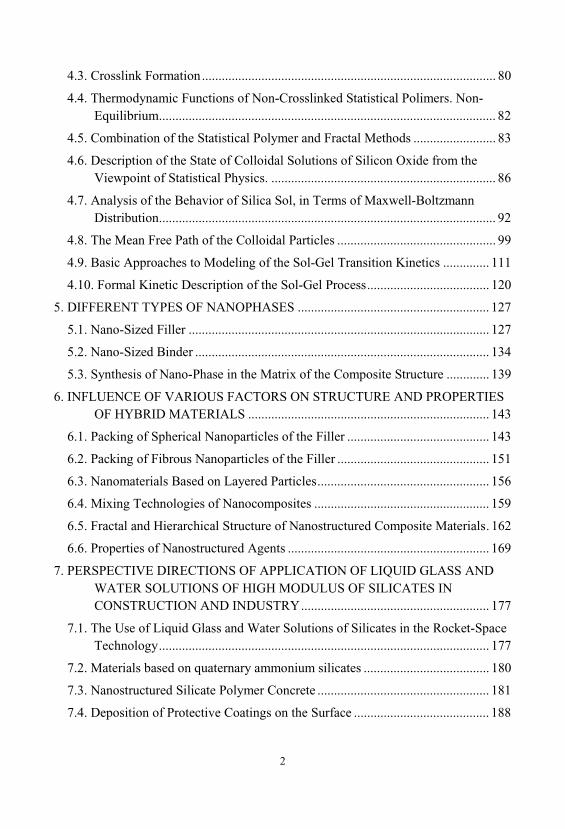
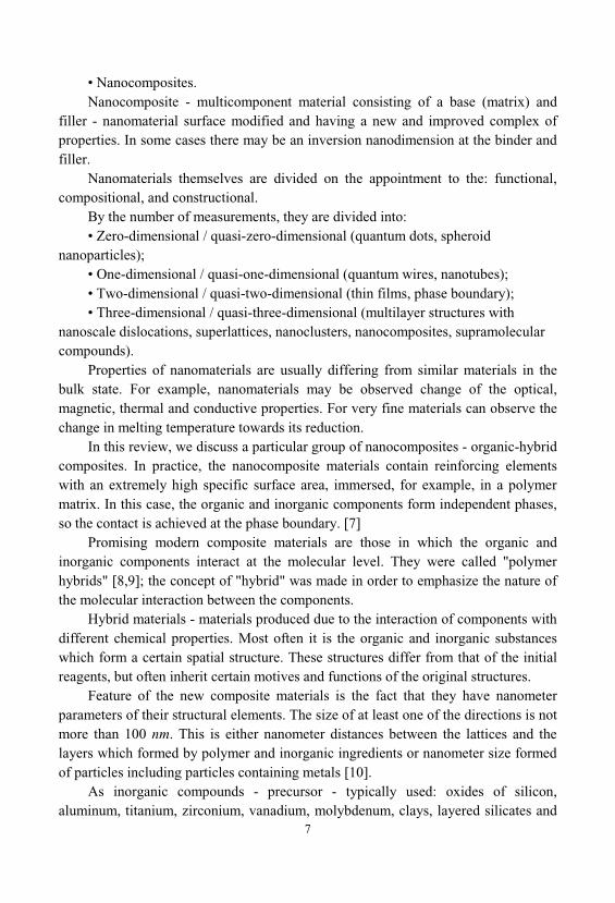
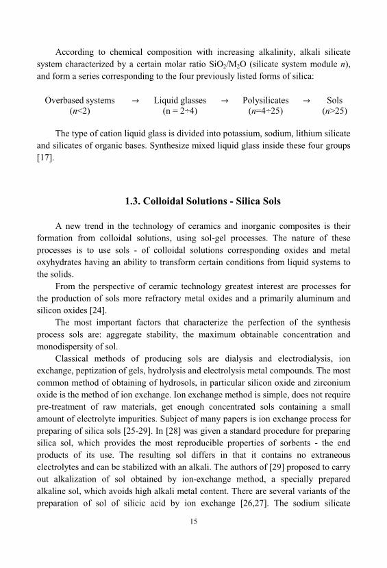
The following experiments investigated the influence of the polymerization ofsilica at a temperature in the alkaline region. It was established experimentally thatthe growth of particles under the influence of temperature occurs mainly in the first60 minutes (Figure 2). Then the rate of decrease of the specific surface sharplyreduced. Thus, during the first 60 minutes, the particle size increases 2÷2.5 times andfurther it does not change significantly [41].
Effect of temperature was investigated in the range of 60 ÷ 100 sols samplesproduced based on the liquid glass and sodium metasilicate with a concentration of3% silica. Thermostating was carried out for 60 minutes, pH 8 of the sols.
As seen from Figure 2, the temperature increases the particle size values in theentire range is significantly increased, each temperature corresponds to the finalparticle size (3 to 7 nm). Particle size growth occurs due to acceleration of thepolymerization reaction and increase the solubility of SiO2, wherein the dispersionmedium enriched in hydroxyl ions, which further speeds up the process.
18
Figure 2. The influence of thetime temperature control on thesize of colloidal particles of silicasol.
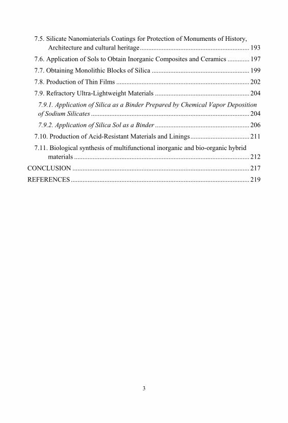
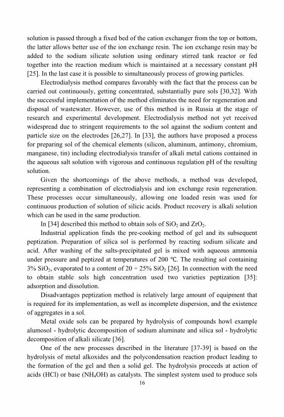
In addition, experimental data showed (Figure 3), the average size of thecolloidal particles in the sols obtained from liquid glass at all temperatures somewhatmore than in the case of sodium metasilicate, which is likely related to greater degreeof polymerization of the silicon-oxygen skeleton for higher silica modulus in liquidglass than sodium metasilicate.
Figure 3. Effect of temperatureand the time temperature controlon the particle size of the colloidalsilica sol: 1 - of liquid glass; 2 - of sodium metasilicate.
Thus, the experimentally obtained time and temperature dependences of theparticle size, showing the so-called the aging process of sols. The aging process of sol- is relatively slow, with respect to the gelation process of changing its properties
19
associated with the polycondensation reactions and aggregation. The aging processwithout additional effects may go into the process of gelation. Aging of acid silica solappears to change its effective viscosity due to aggregation of particles. The agingprocess alkaline silica sol manifests itself in the change of the distribution function ofthe size of its particles, increasing the average size of its particles.
Solutions for a number of technological problems using sol-gel technology andfor long experimental work are often necessary to have a batch of sol unchangedproperties. Stability or change the properties of low concentrated of acid silica sol canbe identified by a change in its effective viscosity [42]. To illustrate this methodfollowing experiment was performed [43].
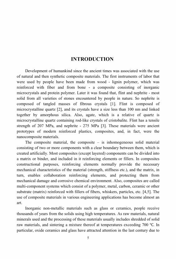
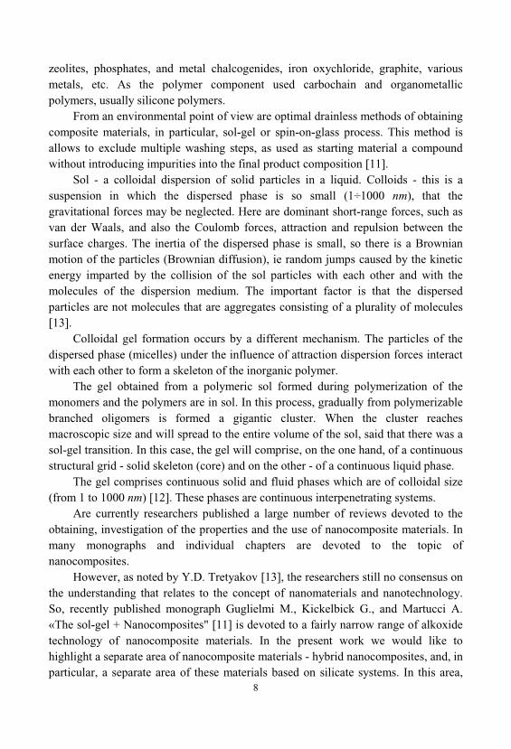
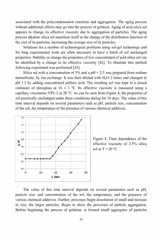
Silica sol with a concentration of 5% and a pH = 2.5 was prepared from sodiummetasilicate, by ion exchange. It was then diluted with H2O 2 times and changed topH 1.2 by adding concentrated sulfuric acid. The resulting sol was kept in a closedcontainer of plexiglass at 18 ± 1 . Its effective viscosity is measured using acapillary viscometer VPL-2 at 20 . As can be seen from Figure 4, the properties ofsol practically unchanged under these conditions during for 16 days. The value of thistime interval depends on several parameters such as pH, particle size, concentrationof the sol, the temperature of the presence of various chemical additives.
Figure 4. Time dependence of theeffective viscosity of 2.5% silicasol at T = 20 .
The value of this time interval depends on several parameters such as pH, particle size, and concentration of the sol, the temperature, and the presence ofvarious chemical additives. Further, processes begin dissolution of small and increasein size, the larger particles. Begin to show the processes of particle aggregation. Before beginning the process of gelation, is formed small aggregates of particles
20
which are moving freely in the volume of the sol. This increase in particle size andappearance of the aggregates results in an increase in viscosity of the entire system.
1.4. Metal Alkoxides
The alkoxides of chemical elements form a class of compounds, the practicalvalue of which are large and are growing [39].
After the publication of the first review on metal alkoxides [1] in 1960 thischemistry field started to develop intensively; the review [2] (1967) already containsmore than 300 links and the review [3] 1978 contains 320 links. The most significantsuccesses of recent years include studies of transition metals alkoxides [3], usingmethods of electron spectroscopy, magnetochemistry, x-ray and NMR spectroscopyon the basis of the representations of the ligand-field theory. Industrial value ofalkoxides associated with their use as components soluble catalysts Ziegler-Natta inthe process of olefins polymerization, as well as source materials for the productionof pure metal oxides [3]. In the journal of the Russian Academy of Sciences RussianChemical Reviews in the period after 2003 was published on 13 reviews on thesynthesis and application of the various metals alkoxides.
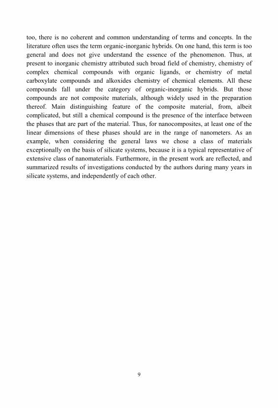
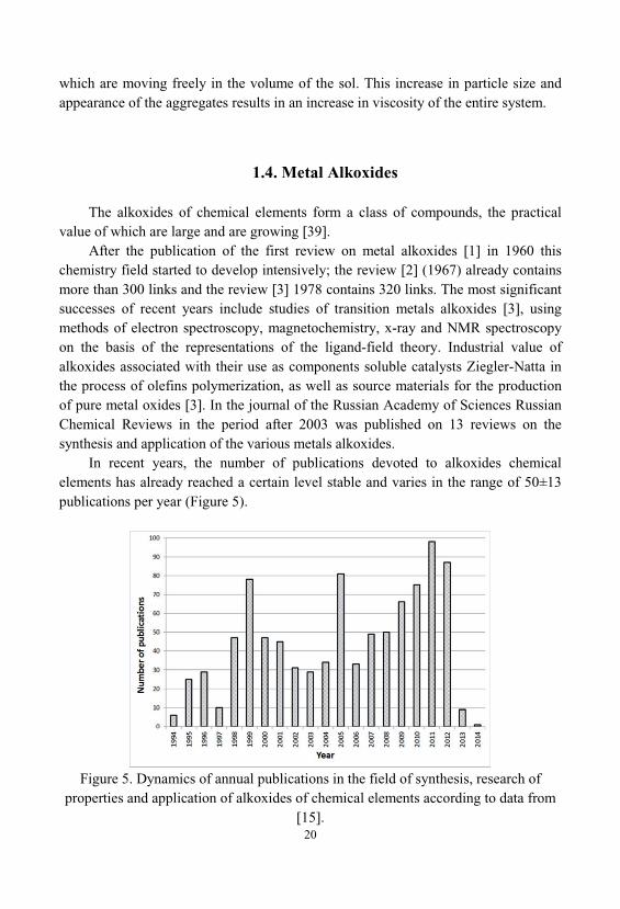
In recent years, the number of publications devoted to alkoxides chemicalelements has already reached a certain level stable and varies in the range of 50±13publications per year (Figure 5).
Figure 5. Dynamics of annual publications in the field of synthesis, research ofproperties and application of alkoxides of chemical elements according to data from
[15].
21
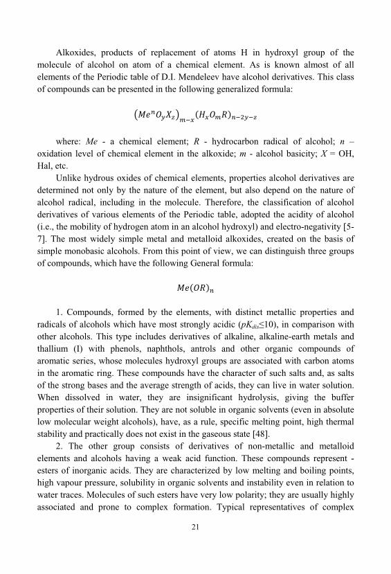
Alkoxides, products of replacement of atoms H in hydroxyl group of themolecule of alcohol on atom of a chemical element. As is known almost of allelements of the Periodic table of D.I. Mendeleev have alcohol derivatives. This classof compounds can be presented in the following generalized formula:
where: Me - a chemical element; R - hydrocarbon radical of alcohol; n –oxidation level of chemical element in the alkoxide; m - alcohol basicity; X = OH, Hal, etc.
Unlike hydrous oxides of chemical elements, properties alcohol derivatives aredetermined not only by the nature of the element, but also depend on the nature ofalcohol radical, including in the molecule. Therefore, the classification of alcoholderivatives of various elements of the Periodic table, adopted the acidity of alcohol(i.e., the mobility of hydrogen atom in an alcohol hydroxyl) and electro-negativity [5-7]. The most widely simple metal and metalloid alkoxides, created on the basis ofsimple monobasic alcohols. From this point of view, we can distinguish three groupsof compounds, which have the following General formula:
1. Compounds, formed by the elements, with distinct metallic properties andradicals of alcohols which have most strongly acidic (pKdis 10), in comparison withother alcohols. This type includes derivatives of alkaline, alkaline-earth metals andthallium (I) with phenols, naphthols, antrols and other organic compounds ofaromatic series, whose molecules hydroxyl groups are associated with carbon atomsin the aromatic ring. These compounds have the character of such salts and, as saltsof the strong bases and the average strength of acids, they can live in water solution. When dissolved in water, they are insignificant hydrolysis, giving the bufferproperties of their solution. They are not soluble in organic solvents (even in absolutelow molecular weight alcohols), have, as a rule, specific melting point, high thermalstability and practically does not exist in the gaseous state [48].
2. The other group consists of derivatives of non-metallic and metalloidelements and alcohols having a weak acid function. These compounds represent -esters of inorganic acids. They are characterized by low melting and boiling points, high vapour pressure, solubility in organic solvents and instability even in relation towater traces. Molecules of such esters have very low polarity; they are usually highlyassociated and prone to complex formation. Typical representatives of complex
22
ethers can be, for example, alkylborates, whose properties are considered in detail in[51-55]. However, it should be noted that the above General characteristics of thecompounds of this group largely inherent in alcohol-derived metals III-VIII group ofthe Periodic table [44,48-50,56,61-63].
3. Typical representatives of compounds of the third group of alkoxides, arecompounds, which include the active metal and alkoxide radical of alcohol, aciddissociation constant of which pKa>>10. This group includes derivatives of metals I, II main subgroup of the Periodic table, thallium(I) and aliphatic alcohols. The natureof chemical bonds Me—OR they occupy an intermediate position between the polarphenolates and nonpolar esters, which determines the peculiarities of their properties. These alkoxides, as esters of inorganic acids, extremely sensitive to the action of amoisture, and sometimes (as in the case of Li) associated and they often observedcomplex formation. By analogy with the phenolates, alkoxides this group is capableof electrolytic dissociation. Their alcoholic solutions have significantelectroconductivity and sometimes react in ionic form; they are not soluble in organicsolvents (except alcohols). However, unlike the compounds of the first two classes, these alkoxides not melt and not distillate, their thermal decomposition occurs at 200-300° [48]. Comparative properties of alkoxides various elements presented in table 1.
In recent years began to develop intensively work on the synthesis of mixedalkoxide compounds. This is due, primarily, to the development of such industries asnanotechnology, technology of high-temperature superconductors, electronics, etc. [39,58-60].
Consider the basic methods for the synthesis of metal alkoxides. Some of thesemethods are used to produce alkoxy derivatives of silicon. Other substances arenecessary for the preparation of intermediates in the synthesis of complex, polynuclear alkoxides of silicon and other elements.
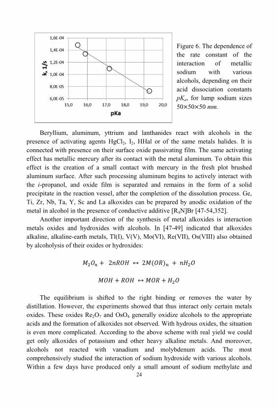
The main direction of the synthesis of metal alkoxides is direct synthesis in theinteraction of metal and alcohol. Alkali and alkaline earth metals alkoxides producedby interaction of metal with alcohol. Sometimes this reaction occurs in solution ofhydrocarbon or liquid NH3 [47]. This is the easiest and most reliable way of thesemetals alkoxides preparation. However, the industrial implementation of this processis associated with a number of technical troubles, due to the high activity of thesemetals. Already with the same metal as potassium is almost impossible to work undernormal conditions, in connection with the self-ignition in the air. The most commonare very developed and industrial processes for the manufacture of sodium alkoxides. The process of interaction of metallic sodium with alcohols occurs rapidly; however, this process is well regulated. The main factor determining the rate of interaction ofsodium with alcohols is the surface area of contact between the solid and liquidphases. The second important factor is the degrees of acidity have used alcohol.
23
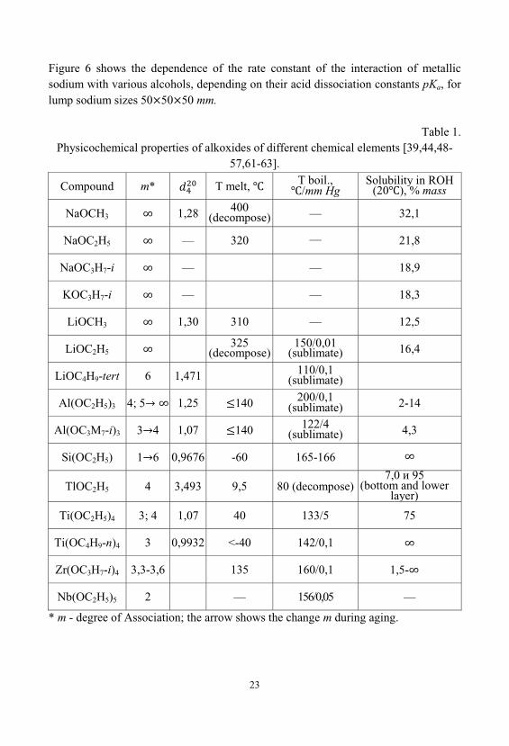
Figure 6 shows the dependence of the rate constant of the interaction of metallicsodium with various alcohols, depending on their acid dissociation constants pKa, forlump sodium sizes 50 50 50 mm.
Table 1. Physicochemical properties of alkoxides of different chemical elements [39,44,48-
57,61-63].
Compound m* T melt, T boil., /mm Hg
Solubility in ROH(20 ), % mass
NaOCH3 1,28 400(decompose) — 32,1
NaOC2H5 — 320 — 21,8
NaOC3H7-i — — 18,9
KOC3H7-i — — 18,3
LiOCH3 1,30 310 — 12,5
LiOC2H5325
(decompose)150/0,01
(sublimate) 16,4
LiOC4H9-tert 6 1,471 110/0,1(sublimate)
Al( 2H5)3 4; 5 1,25 140 200/0,1(sublimate) 2-14
Al( 3 7-i)3 3 4 1,07 140 122/4(sublimate) 4,3
Si(OC2H5) 1 6 0,9676 -60 165-166
TlOC2H5 4 3,493 9,5 80 (decompose)7,0 95
(bottom and lowerlayer)
Ti(OC2H5)4 3; 4 1,07 40 133/5 75
Ti( 4 9-n)4 3 0,9932 <-40 142/0,1
Zr(OC3H7-i)4 3,3-3,6 135 160/0,1 1,5-
Nb(OC2H5)5 2 — 156/0,05 —
* m - degree of Association; the arrow shows the change m during aging.
24
Figure 6. The dependence ofthe rate constant of theinteraction of metallicsodium with variousalcohols, depending on theiracid dissociation constantspKa, for lump sodium sizes50 50 50 mm.
Beryllium, aluminum, yttrium and lanthanides react with alcohols in thepresence of activating agents HgCl2, I2, HHal or of the same metals halides. It isconnected with presence on their surface oxide passivating film. The same activatingeffect has metallic mercury after its contact with the metal aluminum. To obtain thiseffect is the creation of a small contact with mercury in the fresh plot brushedaluminum surface. After such processing aluminum begins to actively interact withthe i-propanol, and oxide film is separated and remains in the form of a solidprecipitate in the reaction vessel, after the completion of the dissolution process. Ge, Ti, Zr, Nb, Ta, Y, Sc and La alkoxides can be prepared by anodic oxidation of themetal in alcohol in the presence of conductive additive [R4N]Br [47-54,352].
Another important direction of the synthesis of metal alkoxides is interactionmetals oxides and hydroxides with alcohols. In [47-49] indicated that alkoxidesalkaline, alkaline-earth metals, Tl(I), V(V), Mo(VI), Re(VII), Os(VIII) also obtainedby alcoholysis of their oxides or hydroxides:
The equilibrium is shifted to the right binding or removes the water bydistillation. However, the experiments showed that thus interact only certain metalsoxides. These oxides Re2O7 and OsO4 generally oxidize alcohols to the appropriateacids and the formation of alkoxides not observed. With hydrous oxides, the situationis even more complicated. According to the above scheme with real yield we couldget only alkoxides of potassium and other heavy alkaline metals. And moreover, alcohols not reacted with vanadium and molybdenum acids. The mostcomprehensively studied the interaction of sodium hydroxide with various alcohols. Within a few days have produced only a small amount of sodium methylate and
25
ethylate, with a yield less than 0.5%. Ethanol and other heavier alcohols themselvesacted as a dehydrating agent, and the resulting distilled water in the form azeotrope. The use of such azeotropic agents of water distillation, as benzene and toluene, practically not changed the situation.
This scheme was developed only technology of production of potassiumbutoxide. The potassium hydroxide solution was loaded into a reactor. Heredownload the estimated amount of the i-butanol and benzene. Benzene is used as acomponent forming azeotrope with water and butanol. Boiling point azeotropebenzene-water-butanol 92-94 .
When you start, fill the measuring tank-separator by i-butanol, once on severalsyntheses. In the reactor start the mixer and send superheated steam in steam-waterjacket. Benzene and i-butanol circulates in the synthesis process. Formed ternaryazeotrope (water-benzene-butanol) out of the top of the reactor and gets in therectification column, which is enriched azeotropic mixtures. The speed and extent ofthe process are controlled by means of thermocouples installed on top of the columnand allocation of water in the measuring tank-separator. Temperature 92-107 onthe top of the column corresponds with the beginning and end of the reaction. Theazeotropic vapors are condensed in the heat exchanger cooled by water. From a heatexchanger, separated liquid phase of water, butanol and benzene, leaving the tubespace, should have temperature of about 25 . Benzene, butanol and water go inmeasuring tank-separator, a pre-filled i-butanol. In the process of synthesis of theproduct, benzene and butanol from the measuring tank-separator is returned via thehydraulic lock back into the system of synthesis. The water through the lower fittingof measuring tank-separator, excreted from the cycle.
The process is complete when the measuring tank-separator ceases to stand outof the water and the temperature of the top of the column is 98-99 . After the end ofthe synthesis distilled benzene and excess of i-butanol, and the finished products pourout.
Also common direction of synthesis of metal alkoxides is interaction of alcoholwith the halides of the chemical elements. Rather universal synthesis of alkoxidesusing the method of alcoholysis of a number of compounds:
where X = N, Hal R', NH2, NO2, N[Si(CH3)3]2. Alcoholysis is the exchange reaction between chemical compound and alcohol.
This forms the hydride of the corresponding compounds, which can be removed fromreaction medium in the form of gas. In this case, the reaction was going to end. If thecorresponding hydride soluble in alcohol, which is used for the alkoxide synthesis,
26
during the reaction comes chemical equilibrium and the product yield is reduced. Inaddition, the application of this method is limited by the difficulty of synthesis of
n. Even when alcoholysis of such compounds troubles appear disconnecting the
last X-groups; they are conditioned by steric factor. A typical example is the reactionof synthesis of tetra-butoxytitanium. In the case of the interaction of titanium tetra-chloride and n-butanol only the process of alcoholysis first three chlorine atomspasses completely.
To replace the last chlorine atom is a need for further shift the equilibrium underthe action of NH3 or different substituted amines:
A modification of this method of synthesis of metal alkoxides is their synthesisthrough interaction pyridinium salts of halide metallates with NH3:
where = pyridine, = Zr, Ce(IV), Pu(IV), UO3+, UO22+. However,
application of this method is limited by the number of compounds that give stablehalide metallates compounds with pyridinium bases.
Another common direction of synthesis of metal alkoxides is exchange reactionswith alcohols, transesterification. The most easily derived alkoxides metals with lightalcohols, however, the process of synthesis of alkoxides based on fatty and complexalcohols, much more difficult. The decision of problems of synthesis of suchalkoxides is achieved by using the exchange reactions with the correspondingalcohols, by analogy with the process of esters transesterification. These processesare as follows:
The equilibrium of the reaction of transesterification alkoxide other alcohol shiftto the right distillation more easily boiling of alcohol or distillation of azeotrope ROHwith benzene or frequent introduction of new portions ROH. In case when both ofalcohols have similar boiling point, suitable replacement ROH on an ester:
27
The displacement of equilibrium to the right side is usually by distillation of themore volatile alcohol or ester. This process was performed on a process plant issimilar to that described in section 2.2.
An important direction of synthesis of metal alkoxides is exchange reactionsbetween the halides of chemical elements and metal alkoxides with highelectronegativity. Alkoxides polyvalent metals synthesized by alkoxysilation of theirhalides by alkoxides metals with high electronegativity, primarily alkali metals ormixture of anhydrous ammonia and appropriate alcohols, usually in the alcohol oralcohol-benzene solution, for example:
where = Na, K, Li, NR4; n 3. At synthesis of soluble alkoxides use sodiumalkoxides, with NaCl precipitates. In conditions of industrial implementation of thisprocess there are problems of separation of the reaction mass from the formed NaClprecipitate. This sediment is fine character with a particle size less than 1 mkm, whichcreates troubles in the implementation of filtration process and capture sediment largeamount of target product, due to capillary forces. This problem has been solved byapplication of the additional dilution of the reaction medium appropriate alcohol or acombination of these processes with the processes of direct interaction of alcoholwith the halides of chemical elements.
At synthesis of insoluble metal alkoxides, such as methylate use lithiumalkoxides - LiOR (LiCl soluble in CH3OH). This reaction occurs through theformation of bimetallic alkoxides.
For the industrial processes of synthesis of various alkoxides of chemicalelements was designed manufacturing plant for synthesis of organometalliccompounds with great performance, with high reliability and operational safety [26].
1.5. Metal organic siloxanes - Intermediate Products betweenChemical Compounds and Nanocomposites
Metal organic siloxanes represent a new class of compounds, extremelyinteresting both from a theoretical and practical point of view. Their main feature isthat they occupy an intermediate position between molecular compounds and
28
nanocomposites, due to their structure. The most detailed review of the chemistry ofthese compounds is made in [289].
Metal organic siloxanes (MOS) - compounds containing fragment =Si(R)OM, where M - metal. This area of chemistry arose as a branch of chemistry oforganosilicon compounds and gradually evolved into an independent scientificdiscipline. Most transformations of metal organic siloxanes occur with participationof fragment SiOM, and coordination properties of metals included in them, play acrucial role the formation of their structure.
Intensive study of individual metal organosiloxanes began in the 1950s., and themain results of these studies are reflected in a number of reviews and monographs[47,290]. The study took place in parallel of oligomeric and polymeric metal organicsiloxanes which contained of metal siloxane fragments in the composition oforganosiloxane chain [291]. Some of these compounds, it is literally in the first yearsafter receiving them, became the objects of industrial production [292]. Polymericmetal organic siloxanes found various applications in technique, such as stabilizers, heat-resistant coatings, auxiliary substances for polymer composites, and polymertonnage products such as building materials water repellents.
The development modern materials science, led to the creation of functionalmaterials having special properties that have been made on the basis of polymermetal organic siloxanes. So were created: heat resistant ceramics and a newgeneration of nanocomposite materials that have unusual electrophysical, nonlinearoptical, magnetic and other properties, as well as polymeric semiconductors. Fornanocomposites with paramagnetic and ferromagnetic properties, was demonstratedability to use high temperature oligomeric transformations in metal organic siloxanes. Another area of application of metal organic siloxanes is to obtain polymericprecursors for production of high-temperature-resistant ceramics.
Found that in the synthesis of metal organic siloxanes in their structure, the self-organization of metal atoms takes place, which leads to the formation of specificclusters. Such metal clusters are of exceptional interest for the control of magnetic, electrophysical and other useful properties of nanosystems obtained by using metalorganic siloxanes, as precursors of metal nanoparticles.
Over the past 20 years, the most interesting results in the chemistry of metalorganosiloxanes were obtained in research in the following areas:
- Development of new methods of forming metal siloxane fragment. This led tothe discovery of new structural type metal organic siloxanes and allowed to expandthe range of metal ions introduced into the siloxane fragment;
- The study of unique chemical transformations of metal organic siloxanes;- Development of general concepts that describe the formation of metal organic
siloxanes structure;
29
- Creation of the concept, which interprets the regularities of rearrangement ofmetal organosiloxane fragments in the structure of metal organic siloxanes;
- Application of metal organic siloxanes as catalyst systems for organicsynthesis processes.
Ways of creation the metal siloxane fragment are very diverse. Some techniquesdeveloped in previous years, are used in modern works in a modified form. One ofthe first methods based on the reaction of organo-silanols with active metals such asalkali metals, zinc and aluminum.
M = K, Na, Zn, Al; n — the metal oxidation level. Currently, this method has retained, the practical significance, especially to
obtain organic silanolates alkali metal, by analogy with their alkoxides. Lessprevalent technique using organo-silanols reaction with organometallic compounds:
R1 = Me, Et, Ph; R2 = Me, Et; M = Zn, Cd. Typically, such reaction is accompanied by evolution of the corresponding
hydrocarbon, but in some cases there is a change of the structure of the hydrocarbonligands of the metal.
The most versatile method for the synthesis of metal organic siloxanes, is basedon the heterofunctional condensation. It can be implemented in various ways. Thismethod allows you to receive both individual and oligomeric MOS (R1, R2, R3, R4
R5 — organic substituents).
X = H, R5, Ac; Y = Hal, R4O, AcO;
Z = H, R4. The combination of X = R, Y = Hal useful for producing polymeric metal
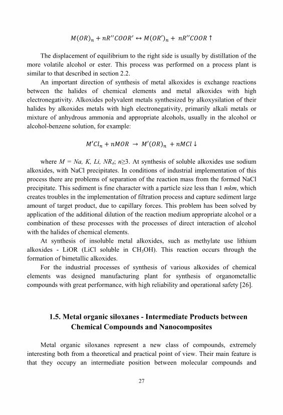
organic siloxanes. This is due to the fact that low molecular weight product which isformed by condensation (R4Hal), does not lead to degradation of the polymer chainof the final product [293]. If the self-condensation of silanol R3SiOH difficult thenused, for example, organometallic derivatives with Y = OR [294]:
30
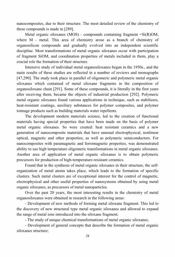
Heterofunctional condensation of silanols with metal halides (X = H, Y = Hal)are used in those cases where the silicon atom (or a metal atom) is a branched group(isopropyl or tert-butyl) [295]:
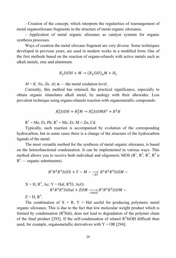
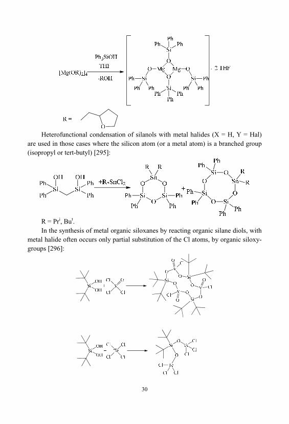
R = Pri, But. In the synthesis of metal organic siloxanes by reacting organic silane diols, with
metal halide often occurs only partial substitution of the Cl atoms, by organic siloxy-groups [296]:
31
If the initial organosilicon compound is Si atom with Bu-group, it is possible toobtain derivatives with one or two Cp groups around the metal atom, which isunattainable by using of starting compounds with Et- and Ph-substituents at thesilicon atom Presence of branched groups at the silicon atom can be used in suchreactions, not only the diorganosilanediols and organosilanetriols. For triols, in thiscase, self-condensation, will be hindered [297]:
. Widespread variant heterofunctional condensation through the interaction of
organo-silanolates of alkali metals with halides of polyvalent metals (M1). Thisprocess is called an exchange reaction:
This reaction is the most universal with its help, were prepared metal organicsiloxanes containing Mg, Zn, Al, Ga, Ti, Zr, Fe, Co, Ni, Cu and other metals [291]. Thus was significantly extended, the number of metal introduced in the metalsiloxane fragment [298,299]. Crucial role in the development possibilities of thismethod has played using of volumetric organic groups at the silicon atom. Furthermore, the exchange reaction allowed to synthesize polyhedral metal organicsiloxanes -based trifunctional organosilicon fragments RSiO1,5. As a result, has beensynthesized new group of metal organic siloxanes with unusual architecture ofwireframes.
General reaction scheme comprises the following steps:- Hydrolysis of organic derivatives of trichlorosilane;- Basic cleavage of polysiloxane;- Exchange interaction of obtained organic silanolates with polyvalent metal
halides. The product of the first stage of the process - the polysiloxane contains silanol
groups Si-OH, which are capable of self-condensation accompanied by elimination ofwater. This results in a partial removal of the metal from the reaction medium in theform of hydroxide. Therefore, at the cleavage step of the polysiloxane, it is necessaryto introduce a metered amount of metallic sodium together with an alkali (in thefollowing reaction scheme it is not shown). Introduced metallic sodium reacts withsilanol groups; it allows you to minimize their possible self-condensation.
32
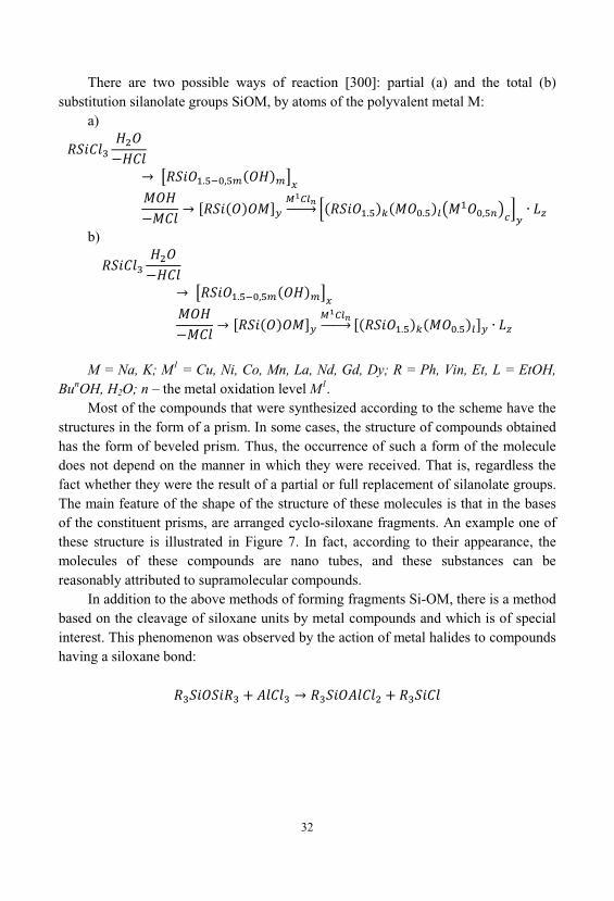
There are two possible ways of reaction [300]: partial (a) and the total (b)substitution silanolate groups SiOM, by atoms of the polyvalent metal M:
a)
b)
M = Na, K; M1 = Cu, Ni, Co, Mn, La, Nd, Gd, Dy; R = Ph, Vin, Et, L = EtOH, BunOH, H2O; n – the metal oxidation level M1.
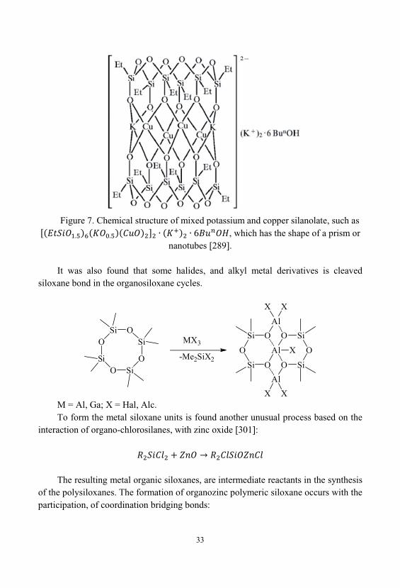
Most of the compounds that were synthesized according to the scheme have thestructures in the form of a prism. In some cases, the structure of compounds obtainedhas the form of beveled prism. Thus, the occurrence of such a form of the moleculedoes not depend on the manner in which they were received. That is, regardless thefact whether they were the result of a partial or full replacement of silanolate groups. The main feature of the shape of the structure of these molecules is that in the basesof the constituent prisms, are arranged cyclo-siloxane fragments. An example one ofthese structure is illustrated in Figure 7. In fact, according to their appearance, themolecules of these compounds are nano tubes, and these substances can bereasonably attributed to supramolecular compounds.
In addition to the above methods of forming fragments Si-OM, there is a methodbased on the cleavage of siloxane units by metal compounds and which is of specialinterest. This phenomenon was observed by the action of metal halides to compoundshaving a siloxane bond:
33
Figure 7. Chemical structure of mixed potassium and copper silanolate, such as, which has the shape of a prism or
nanotubes [289].
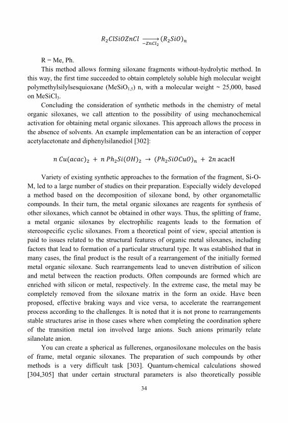
It was also found that some halides, and alkyl metal derivatives is cleavedsiloxane bond in the organosiloxane cycles.
O
SiO Si
O
SiOSi
SiO
Al
O Si
O
OSi
O
Si O
Al
Al
X X
X X
XMX3
-Me2SiX2
M = Al, Ga; X = Hal, Alc. To form the metal siloxane units is found another unusual process based on the
interaction of organo-chlorosilanes, with zinc oxide [301]:
The resulting metal organic siloxanes, are intermediate reactants in the synthesisof the polysiloxanes. The formation of organozinc polymeric siloxane occurs with theparticipation, of coordination bridging bonds:
34
R = Me, Ph. This method allows forming siloxane fragments without-hydrolytic method. In
this way, the first time succeeded to obtain completely soluble high molecular weightpolymethylsilylsesquioxane (MeSiO1,5) n, with a molecular weight ~ 25,000, basedon MeSiCl3.
Concluding the consideration of synthetic methods in the chemistry of metalorganic siloxanes, we call attention to the possibility of using mechanochemicalactivation for obtaining metal organic siloxanes. This approach allows the process inthe absence of solvents. An example implementation can be an interaction of copperacetylacetonate and diphenylsilanediol [302]:
Variety of existing synthetic approaches to the formation of the fragment, Si-O-M, led to a large number of studies on their preparation. Especially widely developeda method based on the decomposition of siloxane bond, by other organometalliccompounds. In their turn, the metal organic siloxanes are reagents for synthesis ofother siloxanes, which cannot be obtained in other ways. Thus, the splitting of frame, a metal organic siloxanes by electrophilic reagents leads to the formation ofstereospecific cyclic siloxanes. From a theoretical point of view, special attention ispaid to issues related to the structural features of organic metal siloxanes, includingfactors that lead to formation of a particular structural type. It was established that inmany cases, the final product is the result of a rearrangement of the initially formedmetal organic siloxane. Such rearrangements lead to uneven distribution of siliconand metal between the reaction products. Often compounds are formed which areenriched with silicon or metal, respectively. In the extreme case, the metal may becompletely removed from the siloxane matrix in the form an oxide. Have beenproposed, effective braking ways and vice versa, to accelerate the rearrangementprocess according to the challenges. It is noted that it is not prone to rearrangementsstable structures arise in those cases where when completing the coordination sphereof the transition metal ion involved large anions. Such anions primarily relatesilanolate anion.
You can create a spherical as fullerenes, organosiloxane molecules on the basisof frame, metal organic siloxanes. The preparation of such compounds by othermethods is a very difficult task [303]. Quantum-chemical calculations showed[304,305] that under certain structural parameters is also theoretically possible
35
formation of structures in the form of nanotubes. In the future, we should expect theappearance of a class of organic metal catenane siloxanes. This compound has a veryunusual topology its molecule comprises two interpenetrating bicyclic fragments[306].
The main practical use, metal organic siloxanes are find as catalysts, and as arule, their catalytic properties, are due the nature of the transition metal. In recentyears, received a special development works on the synthesis of metal complexeswith low coordination numbers containing bulky organic substituents at the siliconatom. They have specific physical and chemical properties due to unusual electronicstructure. In particular, these compounds have been found in tungsten, and they arepromising for the development of modern materials for electronic devices.
Significant potential as a catalyst systems have oligomeric metal organicsiloxanes. Initially, they were used as analogues of inorganic silicates in the processesof petrochemical synthesis. Subsequently, their activity was found in othercommercially important reactions, in particular in the conversion of halogenatedhydrocarbons and exchange halogenation processes. It should be noted that in thecase of oligomeric metal organic siloxanes, plays an important role, not only thenature of the metal, but the type of the siloxane matrix, which determines theavailability of the catalytic center.

36
37
2. SOL-GEL TECHNOLOGY
The most studied of the sol-gel chemistry, certainly system based on silica thatalso appeared historic starting chemistry of sol-gel processes [64]. For the first timein 1845 Ebelmen transparent material received by the slow hydrolysis of the ester ofsilicic acid. In this case the formation of silica gel in the acidification of alkali metalsilicates has been known to scientist’s chemists earlier, but the practical value of thisprocess, no one gave. At the first stage of the sol-gel process, pure silica is mainlyformed ceramic. In the early stages of the sol-gel process study, of pure silicondioxide was mostly formed ceramics. However, it soon became clear that the processmay also be used for the formation of other metal oxides [65]. Furthermore, it wasshown that the mixture of several starting materials, allows obtaining the materials ofa more complex composition. However, in such complicated systems for achievingmaterial homogeneity, it is necessary to know the properties and behavior of eachindividual component in the conditions of the synthesis implementation.
With respect to other methods for synthesis of inorganic oxide materials, including nanoparticles [12,13], the sol-gel process have a number of significantadvantages [10], in particular, these include:
• Ensuring high purity as the starting material, and the resulting product(especially in the case of alkoxides);
• The homogeneity of the distribution of components, including the smallmodifying additives;
• The possibility of achieving homogeneity of the resulting compounds, whichcan go down to the molecular and ionic levels of the material structure;
• The possibility of obtaining new crystalline and amorphous phases, materialswith cations in unusual oxidation States, the synthesis of which traditional methods isdifficult or impossible;
• Regulation of the rheological properties of sols and nanoparticle dispersions, which allows obtaining a wide range of products ranging from coatings to monoliths.
Typically, for the implementation a sol-gel processes use two traditionalapproaches [13], which, however, have a number of branches:
38
• Colloidal method - hydrosols gelation occurring due to the association ofparticles in water suspension (for example, through hydrogen bonds between groupsbelonging to different particles). A variation of this method is the direct depositionand polymerization of the hydrated oxides of chemical elements from solutions oftheir salts, such as soluble silicates;
• Alkoxide method - hydrolytic polycondensation of the starting compounds inaqueous-organic media. The starting materials for this process may be alkoxides, nitrates, etc. Removal of the liquid phase from the obtained products structures iscarried out either under atmospheric, or under supercritical conditions. In recentyears, began to use - non-hydrolytic method. This is an alternative way whichconsists in the interaction a metal halide with oxygen donors - the metal alkoxide inan anhydrous medium.
2.1. Alkoxide Method of Sol-Gel Synthesis
There are alternative reaction scheme when forming the oxide material byprecipitation [66], the hydrothermal treatment [67,68] or using a sol-gel process[69,70]. The Sol-gel process is the most interesting process, due to high technologyapplications in such advanced areas as thin films in electronic or optical devices [71-74]. It begins with a molecular precursors and the formation of oxide grid occurs atrather low temperatures [75]. In contrast to classical solid-phase reactions, thematerial formation is usually carried out in solution. Thus, reactive reagents aredispersed at the molecular level, which provides a low diffusion length of reactingsubstances and thus high reaction rates under mild conditions. In addition, themolecular precursors show the advantage that they can be purified by conventionalmethods such as rectification and chromatography. Consequently, for the formationof materials, are available very pure starting substances, which are very important inapplication areas such as electronics, optics, or biomedical devices.
One of the bases of nanotechnology is that the primary size, initial structuralelements formed in a sol-gel process, is in the nanometer size range. There areseveral technologies, where the sol-gel process is the most advanced state of the art, for example, wear resistant or anti-reflective coatings [76,77]. At present, this processis widely used in the production of nanoparticles [78,79].
The sol-gel process provides control of the structure of various length scales andthus enables to form hierarchically structured materials [80]. The advantages of thesol-gel process with respect to the production of nanocomposite materials are theability to control the mechanism and kinetics of the existing reaction steps. This
39
allows to form the hierarchical materials, for example, to control the properties ofmaterials ranging from the macroscopic and ending, the molecular level. Moreover, because this process takes place under mild conditions, it is possible to makemodifications of materials that are not possible in case of the classical high-temperature ceramic synthesis. For example, due to the low temperature and thepresence of solvent, may be included in the material structure, organic or biologicalcomponents and groups. This makes it possible to carry out the formationorganomineral hybrid materials or nanocomposites those exhibit properties that arecompletely different from conventional materials [81].
Thus, the sol-gel process is more similar to the polymerization process leadingto formation of a three-dimensional ceramic structure, as in the case of formation ofthe polymer network. In this it differs from the classical high-temperature inorganicsolid-phase process. Due to this similarity, the sol-gel process is ideally suited for theformation of nanocomposites, which contain both inorganic and organic polymerstructures.
The sol-gel process is a chemical reaction which starts from an ion or molecularcompound, and allows forming a three-dimensional polymeric network, through theoccurrence of bridging oxo-bonds between the ions (Figure 8), and the release ofwater or other small molecules. Thus, this process is the polycondensation reaction, which leads to a three-dimensional polymer network.
When applying sol-gel process in an aqueous solution, a special kind of a radicalis formed in the first stage, M-OH bond which is unstable and reacts with other typesof radicals.
This first step is hydrolysis. In the second step, the labile group M-OHcondenses with other M-OH or M-OR (when the initial product of the sol-gel processwas used alkoxides of elements) groups to form M-O-M bonds and elimination ofwater or alcohol. Thus is formed a three-dimensional lattice. Typically, the obtainedintermediate not completely condensed in the process, as a consequence of steric andkinetic difficulties. They include into its structure water or OH-groups. Therefore, theproducts obtained correctly be classified as hydrated oxides [82,83].
The progress of hydrolysis and condensation, leads at first to the formation ofsolid particles which are suspended in a liquid, the so-called sol. Particles on thecondensation stages contain at their surface active groups and, therefore, they arecrosslinked to gel. The gel is formed as a solid openwork net and framework whichcontain the liquid phase in the pores.
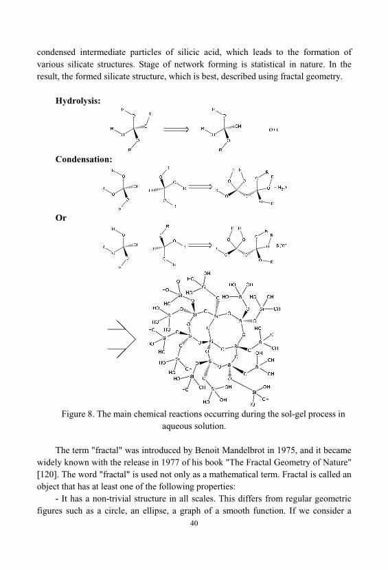
As a rule, the hydrolysis of silicon alkoxides is a pretty slow process. Thus, typically to accelerate the sol-gel processes are used as catalysts, acid or base. Thecatalysts have a significant impact on the final structure of the resulting network. Furthermore, there is also a different reactivity, with no condensed or partially
40
condensed intermediate particles of silicic acid, which leads to the formation ofvarious silicate structures. Stage of network forming is statistical in nature. In theresult, the formed silicate structure, which is best, described using fractal geometry.
Hydrolysis:
Condensation:
Or
Figure 8. The main chemical reactions occurring during the sol-gel process inaqueous solution.
The term "fractal" was introduced by Benoit Mandelbrot in 1975, and it becamewidely known with the release in 1977 of his book "The Fractal Geometry of Nature"[120]. The word "fractal" is used not only as a mathematical term. Fractal is called anobject that has at least one of the following properties:
- It has a non-trivial structure in all scales. This differs from regular geometricfigures such as a circle, an ellipse, a graph of a smooth function. If we consider a
41
small fragment of a regular figure in a very large scale, it will be like a fragment ofthe line. For fractal, zoom in, does not lead to the simplification of the structure, thatis, at all scales, we can see the same complicated picture.
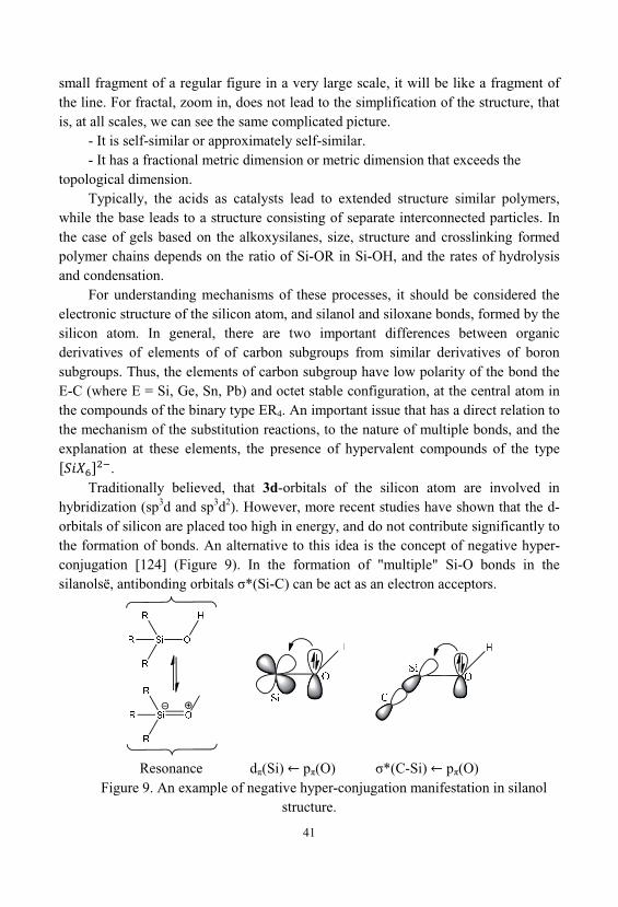
- It is self-similar or approximately self-similar. - It has a fractional metric dimension or metric dimension that exceeds the
topological dimension. Typically, the acids as catalysts lead to extended structure similar polymers,
while the base leads to a structure consisting of separate interconnected particles. Inthe case of gels based on the alkoxysilanes, size, structure and crosslinking formedpolymer chains depends on the ratio of Si-OR in Si-OH, and the rates of hydrolysisand condensation.
For understanding mechanisms of these processes, it should be considered theelectronic structure of the silicon atom, and silanol and siloxane bonds, formed by thesilicon atom. In general, there are two important differences between organicderivatives of elements of of carbon subgroups from similar derivatives of boronsubgroups. Thus, the elements of carbon subgroup have low polarity of the bond theE-C (where E = Si, Ge, Sn, Pb) and octet stable configuration, at the central atom inthe compounds of the binary type ER4. An important issue that has a direct relation tothe mechanism of the substitution reactions, to the nature of multiple bonds, and theexplanation at these elements, the presence of hypervalent compounds of the type
. Traditionally believed, that 3d-orbitals of the silicon atom are involved in
hybridization (sp3d and sp3d2). However, more recent studies have shown that the d-orbitals of silicon are placed too high in energy, and do not contribute significantly tothe formation of bonds. An alternative to this idea is the concept of negative hyper-conjugation [124] (Figure 9). In the formation of "multiple" Si-O bonds in thesilanols , antibonding orbitals *(Si-C) can be act as an electron acceptors.
Resonance d (Si) p (O) *(C-Si) p (O)Figure 9. An example of negative hyper-conjugation manifestation in silanol
structure.
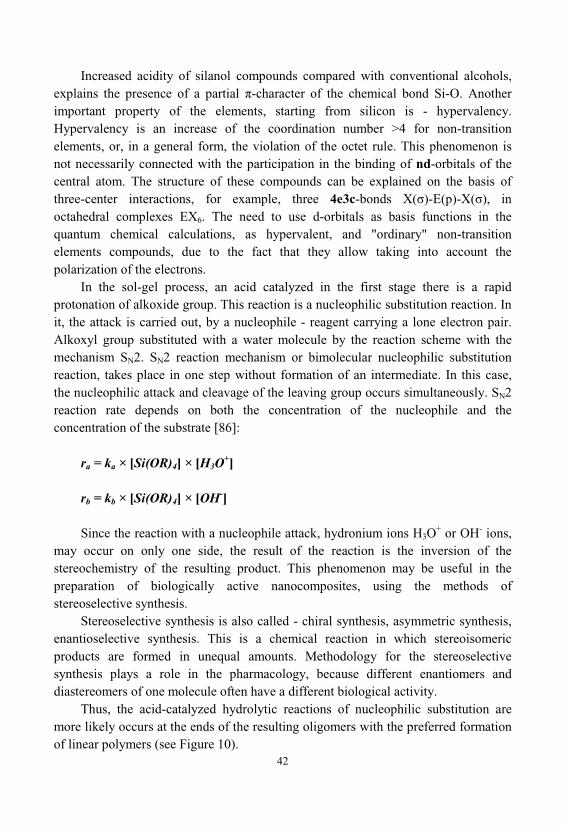
42
Increased acidity of silanol compounds compared with conventional alcohols, explains the presence of a partial -character of the chemical bond Si-O. Anotherimportant property of the elements, starting from silicon is - hypervalency. Hypervalency is an increase of the coordination number >4 for non-transitionelements, or, in a general form, the violation of the octet rule. This phenomenon isnot necessarily connected with the participation in the binding of nd-orbitals of thecentral atom. The structure of these compounds can be explained on the basis ofthree-center interactions, for example, three 4e3c-bonds X( )-E(p)-X( ), inoctahedral complexes EX6. The need to use d-orbitals as basis functions in thequantum chemical calculations, as hypervalent, and "ordinary" non-transitionelements compounds, due to the fact that they allow taking into account thepolarization of the electrons.
In the sol-gel process, an acid catalyzed in the first stage there is a rapidprotonation of alkoxide group. This reaction is a nucleophilic substitution reaction. Init, the attack is carried out, by a nucleophile - reagent carrying a lone electron pair. Alkoxyl group substituted with a water molecule by the reaction scheme with themechanism SN2. SN2 reaction mechanism or bimolecular nucleophilic substitutionreaction, takes place in one step without formation of an intermediate. In this case, the nucleophilic attack and cleavage of the leaving group occurs simultaneously. SN2reaction rate depends on both the concentration of the nucleophile and theconcentration of the substrate [86]:
ra = ka × [Si(OR)4] × [H3O+]
rb = kb × [Si(OR)4] × [OH-]
Since the reaction with a nucleophile attack, hydronium ions H3O+ or OH- ions,
may occur on only one side, the result of the reaction is the inversion of thestereochemistry of the resulting product. This phenomenon may be useful in thepreparation of biologically active nanocomposites, using the methods ofstereoselective synthesis.
Stereoselective synthesis is also called - chiral synthesis, asymmetric synthesis, enantioselective synthesis. This is a chemical reaction in which stereoisomericproducts are formed in unequal amounts. Methodology for the stereoselectivesynthesis plays a role in the pharmacology, because different enantiomers anddiastereomers of one molecule often have a different biological activity.
Thus, the acid-catalyzed hydrolytic reactions of nucleophilic substitution aremore likely occurs at the ends of the resulting oligomers with the preferred formationof linear polymers (see Figure 10).
43
Acid catalysis:
Basic catalysis:
Figure 10. Mechanism of formation of silanol groups, depending on the catalystwhich is used.
From the foregoing, it becomes clear why there is no nucleophilic substitution atthe silicon atom by a dissociative mechanism (D, SN1), which was to take placethrough the formation of intermediate silyl-cations. Instead, it is assumed associativemechanism participation (A, SN2). This assumption is confirmed, the dependence ofthe rate of substitution, the nature of the attacking nucleophile, slowing the reactionin the presence of electron-donating substituents R, while also often observed, inversion of configuration, at the silicon atom.
The direct use of the criterion of inversion of symmetry in silicon chemistry isnot possible, because of the possible increase in the coordination number of thecentral atom and the rearrangement of trigonal bipyramidal intermediates, throughpseudorotation. Such a frontal attack is possible, due to the presence of free siliconatom d-orbitals and low-lying antibonding * orbitals, which stabilize thecoordination number 5. Often observed in nucleophilic substitution reactions, racemization, can lead to an erroneous conclusion about the dissociative mechanism. Actually, however, the racemization is no evidence for the formation of intermediatesilyl-cation as hypercoordinate intermediates can undergo rearrangements(pseudorotation), which may lead to loss of chirality in the resulting inversion orpreservation of chirality from a statistical probability.
In an alkaline medium, polycondensation occurs much faster, and the reactivityincreases with the decreasing number of alkoxy-groups associated with, a siliconatom. Mechanism, in this case, based on the interactions of the nucleophilic hydroxylanion, with, silicon atom, which belongs to the alkoxysilanes. The hydrolysis reactionoccurs through the formation of negatively charged, an intermediate product with a
44
coordination number of 5. The condensation of silanol groups preferably occurs notat the chain ends, and the internal centers of oligomers, which leads to highlybranched, dense structure. Thus, the small spherical particles are formed.
Usually, as the catalyst used simple mineral acids or metal hydroxides, but alsocan also be used fluoride ions F-.
Sol-gel transition depends upon the concentration of the starting reactant, theamount of water, catalyst, temperature and pH. The final solid material has a pluralityof surface OH groups, which can be stabilized by hydrogen bonds with the solventand residual water. Furthermore, after completion of gelation in a large amount in theobtained material are present residual alkoxide groups and free OH groups that arenot participating in the condensation reaction. In the aging step, these groups reactwith each other to form additional quantities of water and alcohols. Furthermore, inthe aging process is observed substance transfer of gel particles from the outer zoneto the contact zone between the particles and thus increase the size of the particlesthat formed a gel. The aging time has great influence on textural properties of thematerial. Further condensation step leads to compaction of the material andcompression of the gel. The aging can be accelerated by increasing the temperature. But it can lead to crack formation in pure gels.
For subsequent applications, the gel should be dried. Removing the liquid from agel is a sharp compression of the gel structure; as a result, a product gets mostshrinkage as compared original form. Compression of the gel structure is known assyneresis. Shrinkage of the gel at syneresis can be up to 50-70% of its original size. During the syneresis occur two types of processes. First - substance transfer from theoutside of the gel particles which form a gel in the inner part of their zone of contactbetween them. Thus, in the contact area of the particles takes place the formation ofbridges between particles, which are formed out of gel material. The second processis determined by the movement of the particles relative to each other, with a gradualdecrease in the pore spaces in the gel. This process is also caused by the transfer ofsubstances of the gel, and certain fluidity, of the gel material.
Upon receipt of a nanocomposite volatile components must be removed out ofthe final material, before its application in the respective products. This process isalso important to obtain a high quality material. When removing the liquid phasefrom the gel structure in the gel pores have a free liquid surface, and thus thecapillary forces arise, they tend to destroy the gel structure. If the resulting capillaryforces exceed the strength of the gel structure, is a phenomenon of decryptation - thedestruction of the gel structure, due to its cracking. In some cases, even the formationof a powdered material. Therefore, the proper conduct of the operation of aging thegel, and the proper carrying out of syneresis and drying processes, provides high-
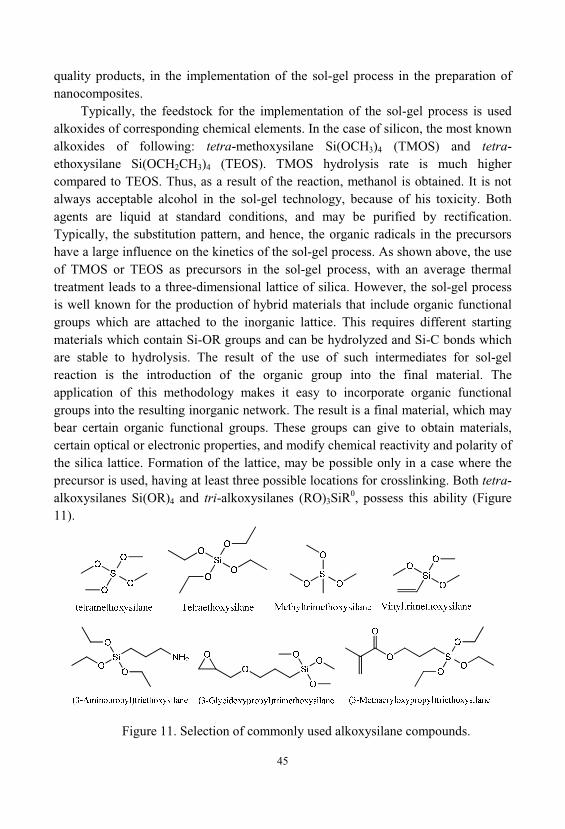
45
quality products, in the implementation of the sol-gel process in the preparation ofnanocomposites.
Typically, the feedstock for the implementation of the sol-gel process is usedalkoxides of corresponding chemical elements. In the case of silicon, the most knownalkoxides of following: tetra-methoxysilane Si(OCH3)4 (TMOS) and tetra-ethoxysilane Si(OCH2CH3)4 (TEOS). TMOS hydrolysis rate is much highercompared to TEOS. Thus, as a result of the reaction, methanol is obtained. It is notalways acceptable alcohol in the sol-gel technology, because of his toxicity. Bothagents are liquid at standard conditions, and may be purified by rectification. Typically, the substitution pattern, and hence, the organic radicals in the precursorshave a large influence on the kinetics of the sol-gel process. As shown above, the useof TMOS or TEOS as precursors in the sol-gel process, with an average thermaltreatment leads to a three-dimensional lattice of silica. However, the sol-gel processis well known for the production of hybrid materials that include organic functionalgroups which are attached to the inorganic lattice. This requires different startingmaterials which contain Si-OR groups and can be hydrolyzed and Si-C bonds whichare stable to hydrolysis. The result of the use of such intermediates for sol-gelreaction is the introduction of the organic group into the final material. Theapplication of this methodology makes it easy to incorporate organic functionalgroups into the resulting inorganic network. The result is a final material, which maybear certain organic functional groups. These groups can give to obtain materials, certain optical or electronic properties, and modify chemical reactivity and polarity ofthe silica lattice. Formation of the lattice, may be possible only in a case where theprecursor is used, having at least three possible locations for crosslinking. Both tetra-alkoxysilanes Si(OR)4 and tri-alkoxysilanes (RO)3SiR0, possess this ability (Figure11).
Figure 11. Selection of commonly used alkoxysilane compounds.
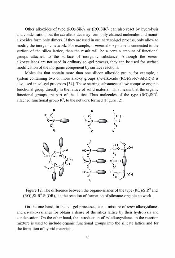
46
Other alkoxides of type (RO)2SiR02 or (RO)SiR0
3 can also react by hydrolysisand condensation, but the bis-alkoxides may form only chained molecules and mono-alkoxides form only dimers. If they are used in ordinary sol-gel process, only allow tomodify the inorganic network. For example, if mono-alkoxysilane is connected to thesurface of the silica lattice, then the result will be a certain amount of functionalgroups attached to the surface of inorganic substance. Although the mono-alkoxysilanes are not used in ordinary sol-gel process, they can be used for surfacemodification of the inorganic component by surface reactions.
Molecules that contain more than one silicon alkoxide group, for example, asystem containing two or more alkoxy groups (tri-alkoxide (RO)3Si-R0-Si(OR)3) isalso used in sol-gel processes [34]. These starting substances allow comprise organicfunctional group directly in the lattice of solid material. This means that the organicfunctional groups are part of the lattice. Thus molecules of the type (RO)3SiR0, attached functional group R0, to the network formed (Figure 12).
Figure 12. The difference between the organo-silanes of the type (RO)3SiR0 and(RO)3Si-R0-Si(OR)3, in the reaction of formation of siloxane-organic network.
On the one hand, in the sol-gel processes, use a mixture of tetra-alkoxysilanesand tri-alkoxysilanes for obtain a dense of the silica lattice by their hydrolysis andcondensation. On the other hand, the introduction of tri-alkoxysilanes in the reactionmixture is used to include organic functional groups into the silicate lattice and forthe formation of hybrid materials.
47
An important parameter for optimization of the sol-gel process, are ratios of thevarious components, for example, the ratio of water to alkoxide C = H2O / M(OR)n;the use of catalysts; and the nature of the alkoxide precursor. The kinetics of theprocess can change significantly, depending on the type of the alkoxy-group used inthe precursor [88].
Materials based on silicon oxide, obtained by the sol-gel process, are oftenporous, in connection with that the final material is a gel. Its pores are filled withsolvent, water and alcohol, formed from the initial silicon alkoxide. Furthermore, theformation of gel in the process of gelation of the sol does not mean that thehydrolysis and condensation reactions are stopped in the reaction vessel. Gelationpoint determines only the time point when there is a sharp increase in viscosity of thereaction mixture due to the three-dimensional crosslinking of the sol particles, andformation an infinite cluster of them. Therefore, as a rule for obtained materials iscarried out aging procedure, over time at ambient or elevated temperature. During theaging, there is a further sealing of material which is conditioned by the continuinghydrolysis and condensation reactions. As a result, the gel is shrunk. Removal of thesolvent from the unmodified gel, for example by its evaporation at elevatedtemperature, generally results in destruction of the gel structure, and ends with theformation of the powder. The reason for this is the high capillary forces that ariseduring the evaporation process of the liquid phase, which destroy the filigree gelnetwork. To eliminate or reduce this phenomenon, the liquid in the pores of the gelcan be replaced by a solvent which provides a low capillary force. One such processis the exchange of solvent in the composition of the gel to a substance that is in itssupercritical condition and thus may be introduced into the material directly in thegas phase. This technique is called drying in the supercritical region. Application ofthis method leads to the preservation of the gel structure. The thus obtained lightmaterials called aerogels. In addition to above described morphology for the gelnetwork, depending on the treatment conditions, can also be prepared differentparticles, fibers, and thin films.
If tetra-alkoxysilanes are the only ones precursors used in the formation of thestructure of the silica, the obtained materials have a hydrophilic surface. Thus, thesematerials can actively interact with water and atmospheric moisture. This isparticularly the case when the materials have high porosity, such as aerogels [89]. The hydrophilic properties of the surface can be changed, if the silanol groups on thesurface are replaced with hydrophobic organic groups. This process can occur afterthe preparation of the material as well as the process of obtaining of the material. Inthe latter case it is possible, if the material is prepared by co-condensation in thepresence of a second functional organic substance.
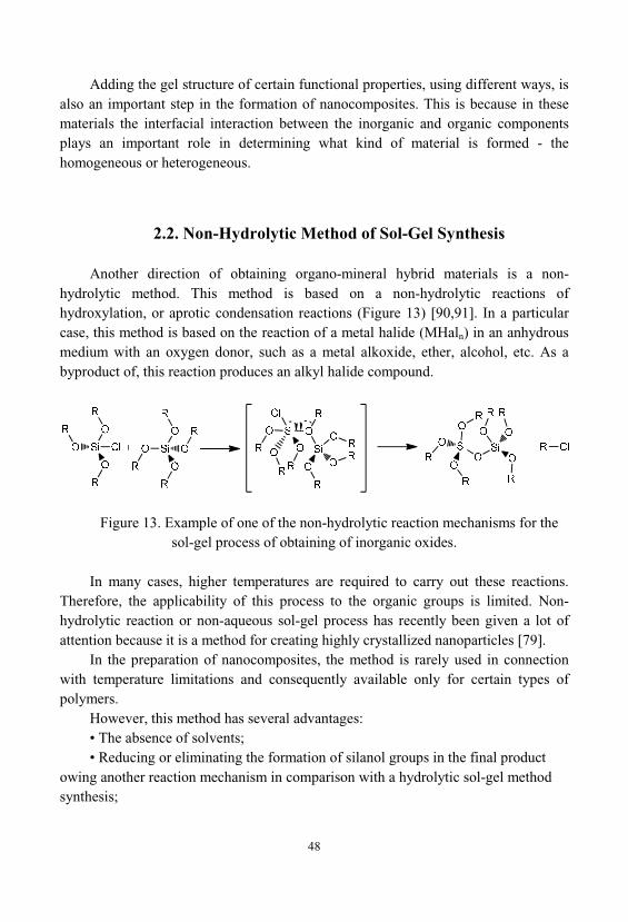
48
Adding the gel structure of certain functional properties, using different ways, isalso an important step in the formation of nanocomposites. This is because in thesematerials the interfacial interaction between the inorganic and organic componentsplays an important role in determining what kind of material is formed - thehomogeneous or heterogeneous.
2.2. Non-Hydrolytic Method of Sol-Gel Synthesis
Another direction of obtaining organo-mineral hybrid materials is a non-hydrolytic method. This method is based on a non-hydrolytic reactions ofhydroxylation, or aprotic condensation reactions (Figure 13) [90,91]. In a particularcase, this method is based on the reaction of a metal halide (MHaln) in an anhydrousmedium with an oxygen donor, such as a metal alkoxide, ether, alcohol, etc. As abyproduct of, this reaction produces an alkyl halide compound.
Figure 13. Example of one of the non-hydrolytic reaction mechanisms for thesol-gel process of obtaining of inorganic oxides.
In many cases, higher temperatures are required to carry out these reactions. Therefore, the applicability of this process to the organic groups is limited. Non-hydrolytic reaction or non-aqueous sol-gel process has recently been given a lot ofattention because it is a method for creating highly crystallized nanoparticles [79].
In the preparation of nanocomposites, the method is rarely used in connectionwith temperature limitations and consequently available only for certain types ofpolymers.
However, this method has several advantages:• The absence of solvents;• Reducing or eliminating the formation of silanol groups in the final product
owing another reaction mechanism in comparison with a hydrolytic sol-gel methodsynthesis;
49
• Easy to achieve homogeneity of the mixture of starting substances, inparticular for non-polar molecules.
At the same time it should be borne in mind that:• It is necessary to take extreme caution when dealing with some highly reactive
reagents, which are used in a non-hydrolytic method;• The interaction of oxygen-containing molecules can be complicated by their
participation in other reactions as oxygen donor. Nonhydrolytic method has been the subject of research in a number of studies
[92-98], which were carried out to identify its advantages in order to obtain inorganicoxides. However, it extremely small used for the synthesis of organo-mineral hybrids. In 1955 has been described the synthesis of several alkyl-and aryl-modified silicates(and linear polyorganosiloxanes) by various combinations of di-methyl-di-chlorosilane, methylphenyldichlorosilane, phenyltrichlorosilane, phenyltriethoxy-silane and feniletildietoksisilana in the presence of iron chloride (III), or aluminumchloride (III), at t = 95÷100 [99]. Checking the obtained results showed that thesereactions occur by the mechanism of hetero functional, stepwise polycondensation, toform an insoluble branched organo-modified silicate. Such passage of processobserved in the case when di- and tri-functional alkoxysilanes are used as the silicon-containing precursor. But additional studies of the samples were not conducted.
Nonhydrolytic sol-gel method of synthesis was studied in the formation of theorgano-modified silicates (called ORMOSIL) with various organic radicals [100]. Forthe formation of the silica lattice were used mono- and di-substituted alkoxy-precursors with alkyl groups of various lengths, from –CH3 to – 10 21. Althoughsimilar hybrids can be obtained, including, and hydrolytic method neverthelessnonhydrolytic approach has some advantages, especially in the synthesis ofhydrophobic hybrids. For example, there is a limitation to the introduction of thecompound containing – 8 17 groups during the synthesis of the hybrid by hydrolysis, this is due to the fact that with increasing in their concentration, the observed phaseseparation of the mixture in the system [101]. Such problems do not arise in theprocess of non-hydrolytic synthesis of silicon-containing compounds having assubstituents even 10 21– groups. The only restriction such interactions the bulkysubstituents is a steric effect that can affect the rate of the condensation reaction, andthe overall degree of condensation.
For example, hybrids of SiO2 – polydimethylsiloxane can be obtained as ahydrolytic or non-hydrolytic sol-gel method. Using the method of hydrolytic sol-gelsynthesis, can be obtained materials which exhibit a different degrees of hardness[102]. Properties of the resulting materials depend on the ratio of precursors, and mayvary, ranging from solid and up to rubber-products [102]. With non-hydrolyticprocess may be synthesized hybrid materials based on silicon-containing compound
50
and polydimethylsiloxane, using as catalyst iron chloride (III). Thus, reactionproducts do not have elastic properties, even when the content of siloxane of 50%.
2.3. Colloidal Method of Sol-Gel Synthesis
The first step in the preparation of nanocomposites of silica is a sol-gel processpreparation of the gel. The colloidal sol-gel method of synthesis involves apreliminary synthesis of colloidal particles, the colloidal particles binding togetherand formation three-dimensional gel networks.
Benefits of colloidal method in comparison with an alkoxide method are asfollows:
• The use of ready-made, aggregately stable sols of polysilicic acid withdifferent particle sizes from 5 to 100 nm;
• Low cost of silicon-containing precursor;• The ability to use various modifying agents that promote changes in: adhesion,
strength, electrical and other properties of the resulting material. The term "colloidal silica" refers to stable dispersions of discrete particles of
amorphous silica (SiO2). It is usually considered hydrophilic sol because particlesstabilized by "solvation" or "hydration". Such a definition excludes from this group, the solutions of polysilicic acids in which the polymer molecules or particles are sosmall that they are unstable. In aqueous solution, the silica at t=25 and pH 7 existsas Si (OH)4 and its solubility is about 0.001 wt. %. At pH 2, it is increased by 1.5times, and at pH 10 - nearly 10-fold. When the monomer concentration in solutionexceeds the value corresponding to the equilibrium solubility, and there is no solidphase on which soluble silica might be precipitate, then the monomer is polymerizedby polycondensation [18]. As a result, the polycondensation of low molecular weightsilicic acid sol the germinal is formed, and takes place growth of its particles. Aggregation of the particles does not occur if the electrolyte concentration is less than0.1÷0.2 N, depending on the silica concentration. In silica sols, the free energy ofinterfacial interaction amorphous silica-water is 50 erg/cm2 [18].
Silica gels are synthesized from molecular silicon-containing precursors. Twogeneral methods are used to initiate of gelation water glass solution:
1. Acidification or partial neutralization of a sodium silicate solution by addingBrönsted acids.
2. Replacing the sodium ions Na+ on hydroxonium ions H3O+ using an ion
exchange resin in acid form, forming thereby a solution of silicic acid and initiatinggelation by addition of a Lewis base (F–) or Brönsted base (OH–).
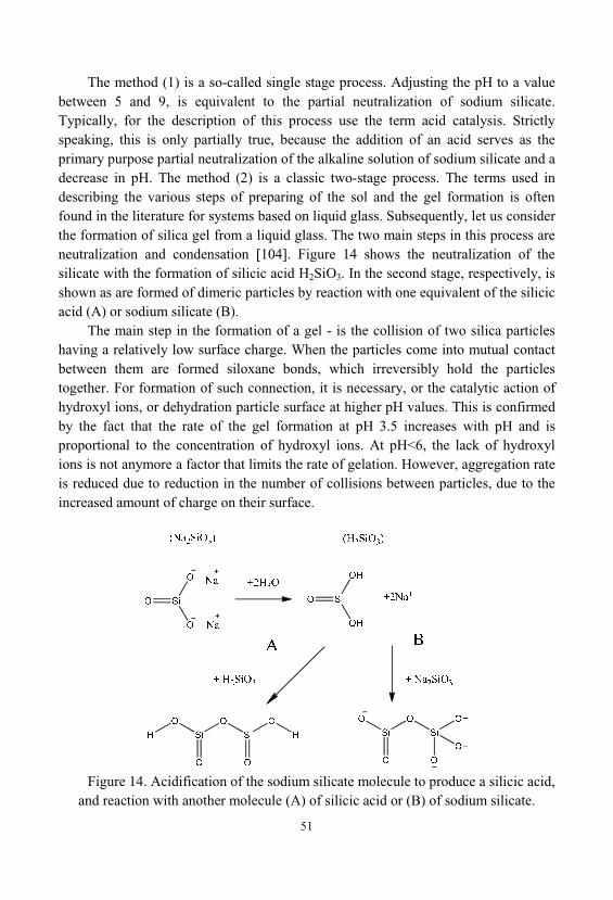
51
The method (1) is a so-called single stage process. Adjusting the pH to a valuebetween 5 and 9, is equivalent to the partial neutralization of sodium silicate. Typically, for the description of this process use the term acid catalysis. Strictlyspeaking, this is only partially true, because the addition of an acid serves as theprimary purpose partial neutralization of the alkaline solution of sodium silicate and adecrease in pH. The method (2) is a classic two-stage process. The terms used indescribing the various steps of preparing of the sol and the gel formation is oftenfound in the literature for systems based on liquid glass. Subsequently, let us considerthe formation of silica gel from a liquid glass. The two main steps in this process areneutralization and condensation [104]. Figure 14 shows the neutralization of thesilicate with the formation of silicic acid H2SiO3. In the second stage, respectively, isshown as are formed of dimeric particles by reaction with one equivalent of the silicicacid (A) or sodium silicate (B).
The main step in the formation of a gel - is the collision of two silica particleshaving a relatively low surface charge. When the particles come into mutual contactbetween them are formed siloxane bonds, which irreversibly hold the particlestogether. For formation of such connection, it is necessary, or the catalytic action ofhydroxyl ions, or dehydration particle surface at higher pH values. This is confirmedby the fact that the rate of the gel formation at pH 3.5 increases with pH and isproportional to the concentration of hydroxyl ions. At pH<6, the lack of hydroxylions is not anymore a factor that limits the rate of gelation. However, aggregation rateis reduced due to reduction in the number of collisions between particles, due to theincreased amount of charge on their surface.
Figure 14. Acidification of the sodium silicate molecule to produce a silicic acid, and reaction with another molecule (A) of silicic acid or (B) of sodium silicate.
52
The overall result of the simultaneous action of these two effects is the highestrate of the gelation at pH 5. As soon as between the particles forming siloxane bondsbegins further deposition of silica at the contact point due to a negative radius ofcurvature of the surface, the resulting particles [105]. This process goes fast above pH5 and slowly at pH 1.5. The rate of gelation, appears proportional to the total surfacearea of the silica present in a given volume of the sol, and increases with increasingtemperature. Substantial data relating to the activation energy of the particleaggregation can only be obtained when the particles have already completed theirgrowth, and stabilized at a higher temperature than provided for in the experiments. Below pH 3.5, the presence of salts of weakly affects the rate of gelation, whereaswater-miscible organic liquids like alcohols slow this process.
Once the sol turns into a gel, at first, increases viscosity of the system, since theparticles bonded together to form branched chains that fill the whole volume, andthen, the gel solidifies. In this case, you must always bear in mind that such anetwork, by capillary structure can hold a significant amount of fluid.
2.4. Soluble Silicates as Precursors are in the Sol-Gel Technologyof Nanocomposites
Soluble silicates of sodium and potassium (water soluble glass) are substanceswhich, in the amorphous glassy state are characterized by particular oxides content -M2O and SiO2, where M - is Na and K. The molar ratio SiO2/M2O is 2.6 ÷ 3.5, whenthe content of SiO2 69 ÷ 76 wt. % of sodium water glass and 65 ÷ 69 wt. % - forpotassium.
Liquid glass can be subdivided by type of alkali cations on the sodium, potassium, lithium, organic bases. By mass or molar ratio in the glass: SiO2 and M2O, where M - is K, Na, Li, or an organic base. In this case, the molar ratio SiO2/M2Ocalled - "silicate module" of liquid glass – n. Secondary characteristic of liquid glassis the content of SiO2 and M2O in wt.%; content of impurity components: A12O3, Fe2O3, CaO, MgO, SO4
2-, etc., and its density (g/cm3). The chemical composition ofthe liquid glasses is characterized by the content of silica and other oxides, regardlessof the specific form of their existence in the solution. In some countries incharacteristic of liquid glasses also include the solutions viscosity.
Sodium liquid glasses typically produce within the silicate modulus values offrom 2.0 to 3.5, with the density of the solutions from 1.3 up to 1.6 g/cm3. Liquidglasses based of potassium have the silicate modulus values in the range of 2.8÷4.0with a density of 1.25÷1.40 g/cm3 [16,17,19,39].
53
Acid resistant building materials based on liquid glass are widely used inconstruction as a silicate polymer concretes, putties, fillers, etc. Soluble sodiumsilicates (liquid glass) are used as binders for the production of heat-resistant andchemically resistant materials. Liquid glass have high cohesive strength, easy andsafe, has a low cost, does not are subject to corrosion, not inflammable volatilecomponents were evaporated and do not adversely affect in the environment of use.
A new trend in the technology of ceramics and inorganic composites, in recentyears, intensive development has received, is the use of sol-gel processes to formmaterials directly from solutions sols. Naturally, in the first row of such materials arethe products based on the silica sol, which in this case are a continuation of a numberof liquid glasses while striving to infinity silicate module [20].
Processes that occur during the curing are complex and diverse. Modern view ofthe general idea of hardening liquid glass itself and in the various homogeneous andheterogeneous systems, the most commonly encountered in practice, presented inseveral reviews [17,19,109]. System based on liquid glass, acting as adhesive orbinding material changes from a liquid to a solid state, in many ways. They can bedivided into three types:
1) The loss of moisture by evaporation at ordinary temperatures;2) Loss of moisture from the system, followed by heating above 100 ;3) The transition to the solid state by introducing specific reagents, which are
called curing agents. Naturally, these three types are used in combination. In solution the degree of polymerization of silicate anions is known to depend
on two factors - the silica modulus and the solution concentration. Each solution has adistribution of degree of polymerization of anions. These two factors determine thedistribution of the degree of polymerization of the anions and imposed on it chargedistribution of the anions.
Sodium metasilicate Na2SiO3, sodium silicates and high modulus, also known aswater glass or liquid glass are inorganic compounds which are readily soluble inwater. Their saturated solution is a viscous liquid with a density of about 1.4 g/cm3
and a pH of about 12.5. Liquid glass is synthesized by the reaction of commercialquartz sand with sodium hydroxide and / or sodium carbonate at elevated temperatureand pressure. Given the wide abundance and inexpensive nature of these reagents, liquid glass is probably is the cheapest source of soluble silicon in the industry. Thepolar nature of the molecule (the presence of ionic pairs, Si-O- and Na+), on the onehand makes it readily soluble in water and, on the other hand, prevents thespontaneous formation of large silica polycondensate or gelling due to electrostaticeffects. In addition, it is simple to use and does not constitute an ignition hazard thatcan occur with silicon alkoxides such as TEOS or TMOS. It is chemically stable inthe long term, under standard conditions of use and storage. Consequently, this type
54
of precursor combines most of, the key advantages needed to produce silicate-basednanocomposites in the industrial scale.
2.5. Preparation of Nanocomposites Through Aerogels
Composite materials obtained by combining two different materials. In general, the composites are developing precisely in order to use to the maximum advantagesof each of the types of materials used and to minimize their disadvantages. Forexample, silica aerogels are brittle substances. Thus, the other component in theobtained material can increase the strength of the material and, in turn, has, forexample, the desired optical properties, high surface area and low density, as a silicaairgel.
In addition to these methods of synthesis and processing, it should beemphasized that the flexibility of the sol-gel processes can increase the variety ofaerogels, except silicon dioxide, aero-gels based materials such that are at themoment still available. Architecture of bulk materials can be adapted by using thetemplate methods [10]. Chemistry of gel may be modified by grafting, either beforeor during [111] or after gelation [112].
Composites and nanocomposites can be created by impregnating the foams orfibrous meshes, dispersing particles [113], powder [104], the polymers [114], or bysynthesis of mixed oxides based on silica [115,116], or other metal oxides [20,39]. Organic silica hybrids [117] can also be produced using plurality techniques such asco-gelling and crosslinking [118] or by reaction with functionalized particles [119].
For the recent years has been a large body of research in the field of preparationof energetic materials. Work was carried out for application of aerogels and sol-gelderivatives, for the preparation of nanostructured composites of energetic (e.g., explosives, propellants and pyrotechnics) and studied their characteristics. Aerogelsare a unique density, composition, porosity and particle size, and low temperature andmild conditions chemical synthesis techniques, all of which makes them attractivecandidates for creating energy nanomaterials.
Using these materials and methods in this field of technology has led to threeprincipal types of energy sol-gel materials [89]:
1) Pyrotechnics - inorganic sol-gel oxidants / metallic fuel (thermitecomposites);
2) A sol-gel derivatives of porous pyrophoric metal powders and films;3) An organic sol-gel fuel / inorganic nanocomposite oxidants (composite solid
propellants and explosives). The behavior of all sol-gel nano energy materials to a large extent depends on
several factors including the surface area, the degree of mixing between phases, the
55
type of mixing (a sol-gel or physical mixing of solids) ways of loading solids, andpresence of impurities. Sol-gel methods are attractive for the field, preparation ofnanostructured energetic materials. These methods offer many options for the form, of the obtained materials, such as monoliths, powders, and films and have a widecompositional flexibility. These attributes, combined with the severity of thesynthetic control of microstructural properties of sol-gel matrix, ensure thepreparation of energetic nanocomposites with reconfigures characteristics.
Energetic materials are divided into three classes [120]:1) Explosives;2) Solid rocket propellants;3) Pyrotechnic materials. Thus, materials may be classified based on their speed of interfacial interaction
of reactants and the type of the energy output. Explosives are materials that react to asupersonic velocity (detonation), and whose reaction products primarily are gaseoussubstances. Rocket propellants are also reacting quickly and give mainly gaseousreaction products, but react unlike explosives at subsonic speeds. Pyrotechnicmaterials tend to react most slowly from all three types of energetic materials andgenerate high-temperature, solid reaction products and few gas, and therebygenerating an intense visible light output.
At least the past two decades, the field of nano researches was one of the mostactive areas of research in various scientific disciplines, and energetic materials werenot an exception to this [120,121]. Nano energy composites were synthesized throughthe use of nano-materials and advanced manufacturing techniques, which arepromising opportunities. Nano Energy composites are defined as a mixture ofoxidizer and fuel particles which have dimensions or at least one critical dimension ofless than 100 nm [122]. Reducing the size increases the surface area of contactbetween the phases of reactants. This has been achieved using a variety of methods, including vapor condensation [123], micellar synthesis, chemical reduction, ultrasonic mixing [124], as well as mechanical mixing methods [125]. Have beenreceived very good results [126]. For example, for the pyrotechnic nanocompositesAl/MoO3 were fixed burning rates by almost three orders of magnitude higher thanconventional mixtures [127]. Such properties of energetic materials as sensitivity toimpact or shock, depends on particle size. Energetic materials with smaller particlesizes may be less sensitive to ignition and thus have better properties in terms ofsafety [128]. These examples provide a good stimulus for the use of nanomaterials, and technologies in the energy fields. With this in mind, aerogels and other gelatinousmaterials obtained from sols were investigated in the last decade as a nanostructuredof energetic materials.
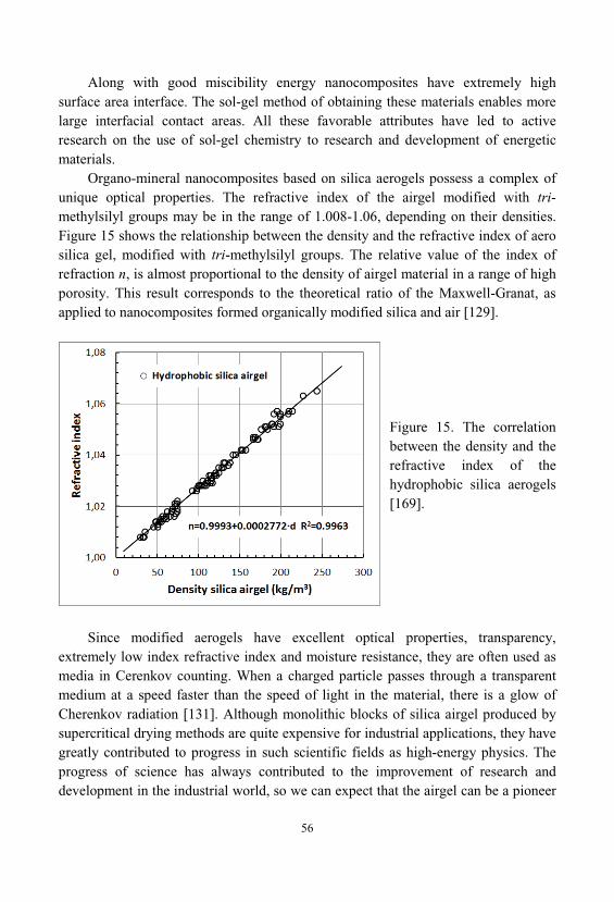
56
Along with good miscibility energy nanocomposites have extremely highsurface area interface. The sol-gel method of obtaining these materials enables morelarge interfacial contact areas. All these favorable attributes have led to activeresearch on the use of sol-gel chemistry to research and development of energeticmaterials.
Organo-mineral nanocomposites based on silica aerogels possess a complex ofunique optical properties. The refractive index of the airgel modified with tri-methylsilyl groups may be in the range of 1.008-1.06, depending on their densities. Figure 15 shows the relationship between the density and the refractive index of aerosilica gel, modified with tri-methylsilyl groups. The relative value of the index ofrefraction n, is almost proportional to the density of airgel material in a range of highporosity. This result corresponds to the theoretical ratio of the Maxwell-Granat, asapplied to nanocomposites formed organically modified silica and air [129].
Figure 15. The correlationbetween the density and therefractive index of thehydrophobic silica aerogels[169].
Since modified aerogels have excellent optical properties, transparency, extremely low index refractive index and moisture resistance, they are often used asmedia in Cerenkov counting. When a charged particle passes through a transparentmedium at a speed faster than the speed of light in the material, there is a glow ofCherenkov radiation [131]. Although monolithic blocks of silica airgel produced bysupercritical drying methods are quite expensive for industrial applications, they havegreatly contributed to progress in such scientific fields as high-energy physics. Theprogress of science has always contributed to the improvement of research anddevelopment in the industrial world, so we can expect that the airgel can be a pioneer
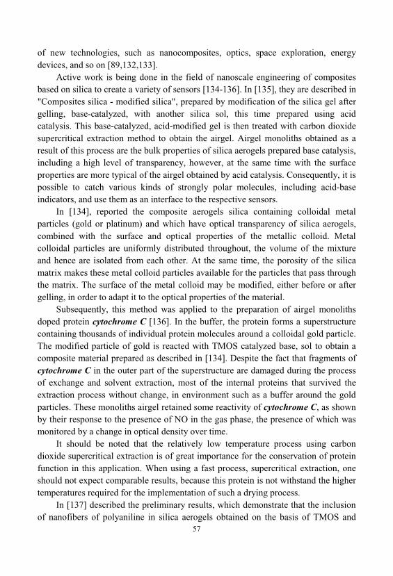
57
of new technologies, such as nanocomposites, optics, space exploration, energydevices, and so on [89,132,133].
Active work is being done in the field of nanoscale engineering of compositesbased on silica to create a variety of sensors [134-136]. In [135], they are described in"Composites silica - modified silica", prepared by modification of the silica gel aftergelling, base-catalyzed, with another silica sol, this time prepared using acidcatalysis. This base-catalyzed, acid-modified gel is then treated with carbon dioxidesupercritical extraction method to obtain the airgel. Airgel monoliths obtained as aresult of this process are the bulk properties of silica aerogels prepared base catalysis, including a high level of transparency, however, at the same time with the surfaceproperties are more typical of the airgel obtained by acid catalysis. Consequently, it ispossible to catch various kinds of strongly polar molecules, including acid-baseindicators, and use them as an interface to the respective sensors.
In [134], reported the composite aerogels silica containing colloidal metalparticles (gold or platinum) and which have optical transparency of silica aerogels, combined with the surface and optical properties of the metallic colloid. Metalcolloidal particles are uniformly distributed throughout, the volume of the mixtureand hence are isolated from each other. At the same time, the porosity of the silicamatrix makes these metal colloid particles available for the particles that pass throughthe matrix. The surface of the metal colloid may be modified, either before or aftergelling, in order to adapt it to the optical properties of the material.
Subsequently, this method was applied to the preparation of airgel monolithsdoped protein cytochrome C [136]. In the buffer, the protein forms a superstructurecontaining thousands of individual protein molecules around a colloidal gold particle. The modified particle of gold is reacted with TMOS catalyzed base, sol to obtain acomposite material prepared as described in [134]. Despite the fact that fragments ofcytochrome C in the outer part of the superstructure are damaged during the processof exchange and solvent extraction, most of the internal proteins that survived theextraction process without change, in environment such as a buffer around the goldparticles. These monoliths airgel retained some reactivity of cytochrome C, as shownby their response to the presence of NO in the gas phase, the presence of which wasmonitored by a change in optical density over time.
It should be noted that the relatively low temperature process using carbondioxide supercritical extraction is of great importance for the conservation of proteinfunction in this application. When using a fast process, supercritical extraction, oneshould not expect comparable results, because this protein is not withstand the highertemperatures required for the implementation of such a drying process.
In [137] described the preliminary results, which demonstrate that the inclusionof nanofibers of polyaniline in silica aerogels obtained on the basis of TMOS and
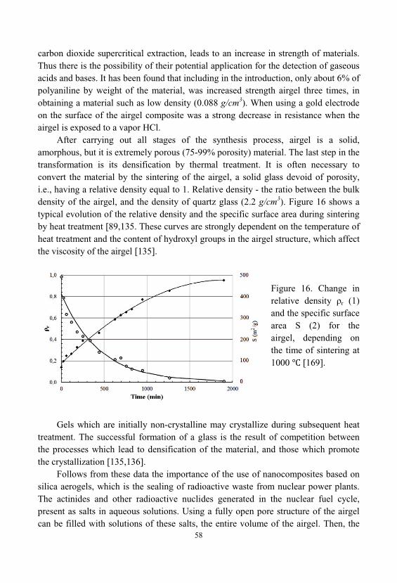
58
carbon dioxide supercritical extraction, leads to an increase in strength of materials. Thus there is the possibility of their potential application for the detection of gaseousacids and bases. It has been found that including in the introduction, only about 6% ofpolyaniline by weight of the material, was increased strength airgel three times, inobtaining a material such as low density (0.088 g/cm3). When using a gold electrodeon the surface of the airgel composite was a strong decrease in resistance when theairgel is exposed to a vapor HCl.
After carrying out all stages of the synthesis process, airgel is a solid, amorphous, but it is extremely porous (75-99% porosity) material. The last step in thetransformation is its densification by thermal treatment. It is often necessary toconvert the material by the sintering of the airgel, a solid glass devoid of porosity, i.e., having a relative density equal to 1. Relative density - the ratio between the bulkdensity of the airgel, and the density of quartz glass (2.2 g/cm3). Figure 16 shows atypical evolution of the relative density and the specific surface area during sinteringby heat treatment [89,135. These curves are strongly dependent on the temperature ofheat treatment and the content of hydroxyl groups in the airgel structure, which affectthe viscosity of the airgel [135].
Figure 16. Change inrelative density r (1)and the specific surfacearea S (2) for theairgel, depending onthe time of sintering at1000 [169].
Gels which are initially non-crystalline may crystallize during subsequent heattreatment. The successful formation of a glass is the result of competition betweenthe processes which lead to densification of the material, and those which promotethe crystallization [135,136].
Follows from these data the importance of the use of nanocomposites based onsilica aerogels, which is the sealing of radioactive waste from nuclear power plants. The actinides and other radioactive nuclides generated in the nuclear fuel cycle, present as salts in aqueous solutions. Using a fully open pore structure of the airgelcan be filled with solutions of these salts, the entire volume of the airgel. Then, the
59
liquid phase was removed by evaporation and the porous composite material (airgel +salt) completely sintered, leading to the synthesis of multicomponent material. Theporous structure of the airgel is used as the receiving vessel. In accordance with thesmall pore size of the airgel, the preparation of such nanocomposites is a very simpleprocess. The size of the domains being formed will depend on the size of the pores inthe airgel, and the content of actinides and other radionuclides in the liquid phase.
However, if trying to fill an airgel with a liquid such as water, capillary forcesmay cause destruction of the airgel [138]. Due to the complexity of the texture of theairgel, a detailed calculation of the local stresses at filling it with liquid to makedifficult, it depends on the surface energy of the liquid-vapor and pore size.
Thus, to avoid cracking of the material during filling, can be offered differentstrategies:
1) Synthesis of airgel with large pores that reduce the magnitude of capillaryforces;
2) Increase the mechanical strength of the airgel due to aging and its partialsintering;
3) Surface functionalization, due to the imparting surface of the airgel ofchelating groups.

60
61
3. HARDENING SYSTEMS ON THE BASIS OF LIQUIDGLASS AND WATER SOLUTIONS OF SILICATES
Processes that occur during the curing are complex and diverse. Modern view ofthe general idea of hardening liquid glass itself and in the various homogeneous andheterogeneous systems, the most commonly encountered in practice, presented inseveral reviews [17,18,109]. System based on liquid glass, acting as adhesive orbinding material changes from a liquid to a solid state, in many ways. They can bedivided into three types:
1) the loss of moisture by evaporation at ordinary temperatures;2) loss of moisture from the system, followed by heating above 100 ;3) the transition to the solid state by introducing specific reagents, which are
called curing agents. Naturally, these three types are used in combination. In solution the degree of polymerization of silicate anions is known to depend
on two factors - the silica modulus and the solution concentration. Each solution has adistribution of degree of polymerization of at anion. These two factors determine thedistribution of the degree of polymerization of the anions and imposed on him thecharge distribution of the anions.
3.1. Hardening at Normal Temperatures by Removing Moisture
The processes occurring in the silicate solution, determined by two reversiblereactions that shown in Figure 17. Polymers formed by the second reaction arepreferably spherical structure, and are formed during polymerization as colloidalparticles charged negatively [18]. Therefore, they do not come together to interact, ifnot created the conditions for coagulation.
62
Figure 17. The silanol groups’ dissociation and polysilicic acids condensationprocesses.
Dimensions of colloidal particles and thus their concentrations are regulated byinternal distillation process. It lies in the fact that the solubility of small silicaparticles in the solution depends on the particle size, and if the particle size isincreased, solubility is decreased. During the internal distillation process, the largeparticles grow due to the dissolution of the smaller particles. For larger particles, theirsolubility is not dependent on size. Therefore, internal distillation, at a certain point, slowing down, and further, stops absolutely. This leads to some particle sizedistribution. This phenomenon is especially characteristic for cases where theformation a silicate solution started from monomeric particles. If a silicate solution isformed by dissolving large polymeric forms of silica, the internal distillation processmay not be developed, or as a secondary process, to obtain a solution and the polymerdistribution of the anions other than the first case. The internal distillation process, especially in the later stages, proceeds rather sluggishly, so old and freshly preparedsolutions may be very different from each other, although the module and theconcentration of the solutions are the same. Sharp dilutions of solutions ortemperature change also lead to changes in the anionic composition.
If evaporate dilute solution having a large silicate unit, the liquid phase isrepresented only by ionic forms of silica. However, because of the hydrolysis causedby a lower concentration of hydroxyl ions in the first reaction, there will be a greateramount of ions of the type, but in much smaller quantities ions . During the evaporation of the solution will start to change in the direction of reducingthe module, since the module is a solid phase are higher than the module sourcesolution (Figure 18). Concentration of will be smaller, and ions more, as it evaporates, will the emergence of new solid phases and, ultimately, would be tofall phase Na4SiO4•mH2O.
63
Figure 18. The initial solutionconcentration of tetrabutylammoniumsilicate and anionic composition ofcrystals obtained from it [139,140]. nL - composition of the liquid phase;nS - composition of the solid phase.
At some concentration of hydroxide ions in a solution of ionic forms of silicahydrolysis goes so far that there are completely hydrolyzed forms have reacheduncharged molecular state Si( )4. If the interaction between the two ions, thesecond type of reaction, it is unlikely due to electrostatic repulsion, then between themolecular and ionic forms, it is possible. So may be obtained polymeric forms ofsilica. They are already in the early stages can take a three-dimensional structurewhere the silicon atoms are connected inside the Si— —Si, and the outer atomshave at least one bond Si—OH. The latter may also exist in the ionic form . With a length of chain, equal to 4÷5, there is a formation of ring structures, whichsubsequently acquire a three-dimensional structure.
Slow evaporation at elevated temperature increases the degree of polymerizationof silicates. Therefore, for obtaining readily soluble alkali silicate powders from theviewpoint of product quality, the process is advantageously carried out at a lowtemperature rapidly using not very concentrated solutions.
Further conversion to the hardened silicate system associated with the slow lossof hydration water in the atmospheric conditions and the absorption of carbon dioxide
that causes the migration of sodium ions to the surface to form the crystallinecarbonate structure, and forming a silica frame with a low water content. This leadsto an increase of water resistance.
For example, a self-hardened, high temperature-resistant, foamed composite isdescribed. An alkali metal silicate-based matrix devoid of chemical water hasdispersed therein inorganic particulates, organic particulates, or a mixture ofinorganic and organic particulates, and is produced at ambient temperature by
64
activating the silicates of an aqueous, air-entrained gel containing matrix-formingsilicate, particulates, flyash, surfactant, and a pH-lowering and buffering agent [102].
3.2. Hardening of Liquid Glass Using Reagents
A special place among hardeners that increase module of liquid glass, take alkalimetal hexafluorosilicates. Their peculiarity lies in the fact that they not only interactwith the alkali, reducing its content, but also to form the silicic acid with itsdecomposition, which significantly plumping a hardening system, lowering itsporosity. Hexafluorosilicate ion is an example of substances that demonstrate theability of the silicon atom to the manifestation of the properties of hypervalent, through the use of free d-orbitals. This phenomenon causes their high activity, particularly in alkaline media. The reaction takes place between hexafluorosilicateion and hydroxide ions according to the following conditional scheme:
This is a typical reaction of the ligand substitution in the complexes, but it isaccompanied by a change in the coordination number of the silicon atom and, asoften happens in such cases, complexes with mixed ligands are very unstable. Thereaction is reversible and takes place in acidic media in the opposite direction. Introduction Na2SiF6 powder in sodium liquid glass, as in other cases, mixing withsolid acidic hardeners immediately causes coagulation of silicate and then gelationoccurs around the hardener grain surface. Therefore, usually sodiumhexafluorosilicate powder is premixed with filler and then a liquid glass.
Upon receipt acid resistant concretes and putties, hexafluorosilicate sodiumadministered in an amount greater than needed to neutralize all the alkali of liquidglass [141]. For example, to neutralize all the alkali contained in the sodium liquidglass (n = 3, = l, 45 g/cm3), sodium hexafluorosilicate requires slightly less than16% by weight of the glass, when n = 2, and = 1.40 g/cm3 need 18 wt. % of Sodiumhexafluorosilicate. Featured recipes offer 25÷ 0 wt.% Na2SiF6 for acid putties[16,17,19,109,141-143]. After neutralization all the alkali entering the liquid glasscomposition, decomposition of sodium hexafluorosilicate is completely stopped, andit is probably that the hardened system practicable simultaneous presence of Na2SiF6, and silica. It is also important to note that in an acidic environment, this reaction goesin the opposite direction when NaF, formed during the manufacture of putties, will bepresent in sufficient concentration in the system. Therefore washing of NaF after
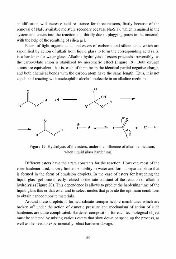
65
solidification will increase acid resistance for three reasons, firstly because of theremoval of NaF, available moisture secondly because Na2SiF6, which remained in thesystem and enters into the reaction and thirdly due to plugging pores in the material, with the help of the resulting of silica gel.
Esters of light organic acids and esters of carbonic and silicic acids which aresaponified by action of alkali from liquid glass to form the corresponding acid salts, is a hardener for water glass. Alkaline hydrolysis of esters proceeds irreversibly, asthe carboxylate anion is stabilized by mesomeric effect (Figure 19). Both oxygenatoms are equivalent, that is, each of them bears the identical partial negative charge, and both chemical bonds with the carbon atom have the same length. Thus, it is notcapable of reacting with nucleophilic alcohol molecule in an alkaline medium.
Figure 19. Hydrolysis of the esters, under the influence of alkaline medium, when liquid glass hardening.
Different esters have their rate constants for the reaction. However, most of theester hardener used, is very limited solubility in water and form a separate phase thatis formed in the form of emulsion droplets. In the case of esters for hardening theliquid glass gel time directly related to the rate constant of the reaction of alkalinehydrolysis (Figure 20). This dependence is allows to predict the hardening time of theliquid glass this or that ester and to select modes that provide the optimum conditionsto obtain nanocomposite materials.
Around these droplets is formed silicate semipermeable membranes which arebroken off under the action of osmotic pressure and mechanism of action of suchhardeners are quite complicated. Hardener composition for each technological objectmust be selected by mixing various esters that slow down or speed up the process, aswell as the need to experimentally select hardener dosage.
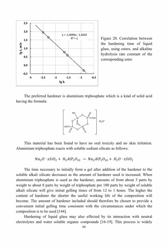
66
Figure 20. Correlation betweenthe hardening time of liquidglass, using esters, and alkalinehydrolysis rate constant of thecorresponding ester.
The preferred hardener is aluminium triphosphate which is a kind of solid acidhaving the formula:
PO
HO
O
O
POO
O
PO
OH
O
Al-
HO
H3O+
This material has been found to have no oral toxicity and no skin irritation. Aluminium triphosphate reacts with soluble sodium silicate as follows:
The time necessary to initially form a gel after addition of the hardener to thesoluble alkali silicate decreases as the amount of hardener used is increased. Whenaluminium triphosphate is used as the hardener, amounts of from about 3 parts byweight to about 8 parts by weight of triphosphate per 100 parts by weight of solublealkali silicate will give initial gelling times of from 12 to 1 hours. The higher thecontent of hardener the shorter the useful working life of the composition willbecome. The amount of hardener included should therefore be chosen to provide aconvenient initial gelling time consistent with the circumstances under which thecomposition is to be used [144].
Hardening of liquid glass may also effected by its interaction with neutralelectrolytes and water soluble organic compounds [16-19]. This process is widely
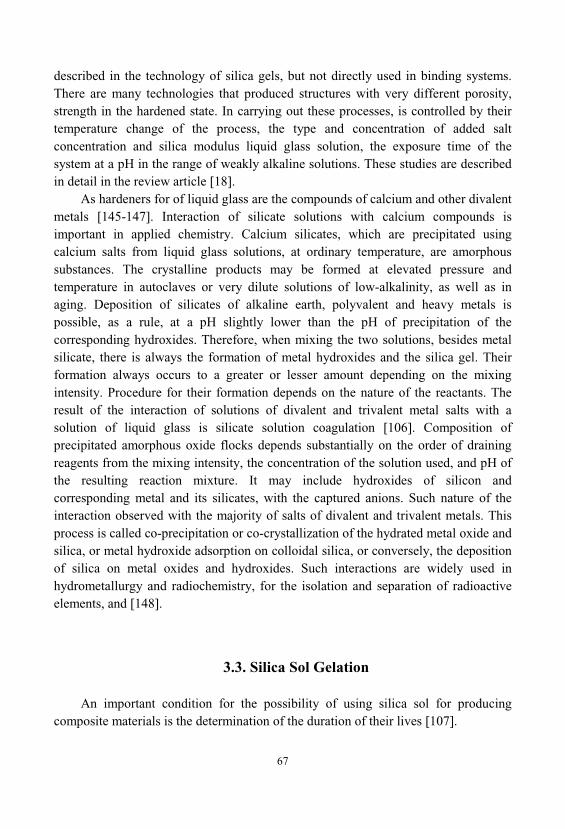
67
described in the technology of silica gels, but not directly used in binding systems. There are many technologies that produced structures with very different porosity, strength in the hardened state. In carrying out these processes, is controlled by theirtemperature change of the process, the type and concentration of added saltconcentration and silica modulus liquid glass solution, the exposure time of thesystem at a pH in the range of weakly alkaline solutions. These studies are describedin detail in the review article [18].
As hardeners for of liquid glass are the compounds of calcium and other divalentmetals [145-147]. Interaction of silicate solutions with calcium compounds isimportant in applied chemistry. Calcium silicates, which are precipitated usingcalcium salts from liquid glass solutions, at ordinary temperature, are amorphoussubstances. The crystalline products may be formed at elevated pressure andtemperature in autoclaves or very dilute solutions of low-alkalinity, as well as inaging. Deposition of silicates of alkaline earth, polyvalent and heavy metals ispossible, as a rule, at a pH slightly lower than the pH of precipitation of thecorresponding hydroxides. Therefore, when mixing the two solutions, besides metalsilicate, there is always the formation of metal hydroxides and the silica gel. Theirformation always occurs to a greater or lesser amount depending on the mixingintensity. Procedure for their formation depends on the nature of the reactants. Theresult of the interaction of solutions of divalent and trivalent metal salts with asolution of liquid glass is silicate solution coagulation [106]. Composition ofprecipitated amorphous oxide flocks depends substantially on the order of drainingreagents from the mixing intensity, the concentration of the solution used, and pH ofthe resulting reaction mixture. It may include hydroxides of silicon andcorresponding metal and its silicates, with the captured anions. Such nature of theinteraction observed with the majority of salts of divalent and trivalent metals. Thisprocess is called co-precipitation or co-crystallization of the hydrated metal oxide andsilica, or metal hydroxide adsorption on colloidal silica, or conversely, the depositionof silica on metal oxides and hydroxides. Such interactions are widely used inhydrometallurgy and radiochemistry, for the isolation and separation of radioactiveelements, and [148].
3.3. Silica Sol Gelation
An important condition for the possibility of using silica sol for producingcomposite materials is the determination of the duration of their lives [107].
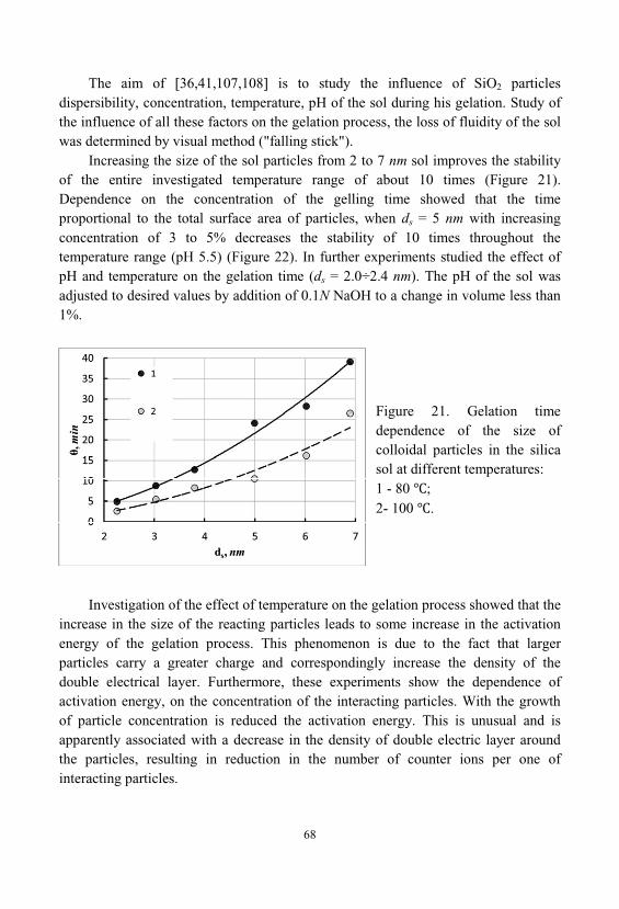
68
The aim of [36,41,107,108] is to study the influence of SiO2 particlesdispersibility, concentration, temperature, pH of the sol during his gelation. Study ofthe influence of all these factors on the gelation process, the loss of fluidity of the solwas determined by visual method ("falling stick").
Increasing the size of the sol particles from 2 to 7 nm sol improves the stabilityof the entire investigated temperature range of about 10 times (Figure 21). Dependence on the concentration of the gelling time showed that the timeproportional to the total surface area of particles, when ds = 5 nm with increasingconcentration of 3 to 5% decreases the stability of 10 times throughout thetemperature range (pH 5.5) (Figure 22). In further experiments studied the effect ofpH and temperature on the gelation time (ds = 2.0÷2.4 nm). The pH of the sol wasadjusted to desired values by addition of 0.1N NaOH to a change in volume less than1%.
Figure 21. Gelation timedependence of the size ofcolloidal particles in the silicasol at different temperatures: 1 - 80 ; 2- 100 .
Investigation of the effect of temperature on the gelation process showed that theincrease in the size of the reacting particles leads to some increase in the activationenergy of the gelation process. This phenomenon is due to the fact that largerparticles carry a greater charge and correspondingly increase the density of thedouble electrical layer. Furthermore, these experiments show the dependence ofactivation energy, on the concentration of the interacting particles. With the growthof particle concentration is reduced the activation energy. This is unusual and isapparently associated with a decrease in the density of double electric layer aroundthe particles, resulting in reduction in the number of counter ions per one ofinteracting particles.
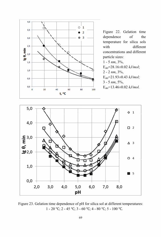
69
Figure 22. Gelation timedependence of thetemperature for silica solswith differentconcentrations and differentparticle sizes: 1 - 5 nm, 3%,
akt=28.16±0.02 kJ/mol; 2 - 2 nm, 3%,
akt=21.93±0.43 kJ/mol;3 - 5 nm, 5%,
akt=13.46±0.02 kJ/mol.
Figure 23. Gelation time dependence of pH for silica sol at different temperatures:1 - 20 ; 2 - 45 ; 3 - 60 ; 4 - 80 ; 5 - 100 .
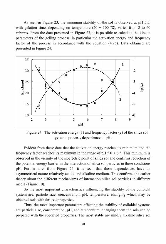
70
As seen in Figure 23, the minimum stability of the sol is observed at pH 5.5, with gelation time, depending on temperature (20 ÷ 100 ), varies from 2 to 60minutes. From the data presented in Figure 23, it is possible to calculate the kineticparameters of the gelling process, in particular the activation energy and frequencyfactor of the process in accordance with the equation (4.95). Data obtained arepresented in Figure 24.
Figure 24. The activation energy (1) and frequency factor (2) of the silica solgelation process, dependence of pH.
Evident from these data that the activation energy reaches its minimum and thefrequency factor reaches its maximum in the range of pH 5.0 ÷ 6.5. This minimum isobserved in the vicinity of the isoelectric point of silica sol and confirms reduction ofthe potential energy barrier in the interaction of silica sol particles in these conditionspH. Furthermore, from Figure 24, it is seen that these dependences have anasymmetrical nature relatively acidic and alkaline medium. This confirms the earliertheory about the different mechanisms of interaction silica sol particles in differentmedia (Figure 10).
So the most important characteristics influencing the stability of the colloidalsystem are: particle size, concentration, pH, temperature, changing which may beobtained sols with desired properties.
Thus, the most important parameters affecting the stability of colloidal systemsare particle size, concentration, pH, and temperature; changing them the sols can beprepared with the specified properties. The most stable are mildly alkaline silica sol
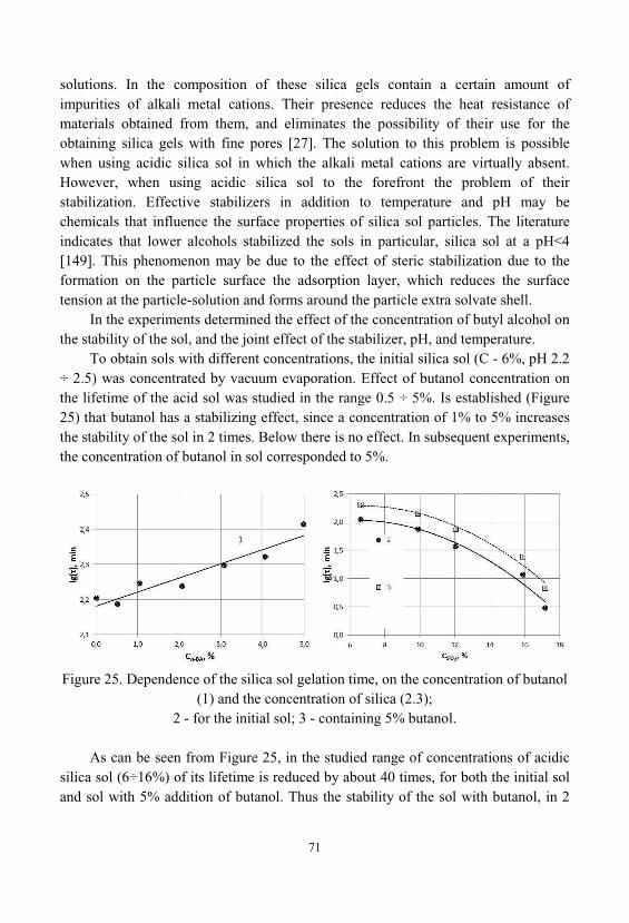
71
solutions. In the composition of these silica gels contain a certain amount ofimpurities of alkali metal cations. Their presence reduces the heat resistance ofmaterials obtained from them, and eliminates the possibility of their use for theobtaining silica gels with fine pores [27]. The solution to this problem is possiblewhen using acidic silica sol in which the alkali metal cations are virtually absent. However, when using acidic silica sol to the forefront the problem of theirstabilization. Effective stabilizers in addition to temperature and pH may bechemicals that influence the surface properties of silica sol particles. The literatureindicates that lower alcohols stabilized the sols in particular, silica sol at a pH<4[149]. This phenomenon may be due to the effect of steric stabilization due to theformation on the particle surface the adsorption layer, which reduces the surfacetension at the particle-solution and forms around the particle extra solvate shell.
In the experiments determined the effect of the concentration of butyl alcohol onthe stability of the sol, and the joint effect of the stabilizer, pH, and temperature.
To obtain sols with different concentrations, the initial silica sol ( - 6%, pH 2.2÷ 2.5) was concentrated by vacuum evaporation. Effect of butanol concentration onthe lifetime of the acid sol was studied in the range 0.5 ÷ 5%. Is established (Figure25) that butanol has a stabilizing effect, since a concentration of 1% to 5% increasesthe stability of the sol in 2 times. Below there is no effect. In subsequent experiments, the concentration of butanol in sol corresponded to 5%.
Figure 25. Dependence of the silica sol gelation time, on the concentration of butanol(1) and the concentration of silica (2.3);
2 - for the initial sol; 3 - containing 5% butanol.
As can be seen from Figure 25, in the studied range of concentrations of acidicsilica sol (6÷16%) of its lifetime is reduced by about 40 times, for both the initial soland sol with 5% addition of butanol. Thus the stability of the sol with butanol, in 2
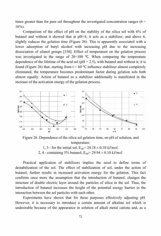
72
times greater than for pure sol throughout the investigated concentration ranges (6 ÷16%).
Comparison of the effect of pH on the stability of the silica sol with 6% ofbutanol and without it showed that at pH<4, it acts as a stabilizer, and above 6, slightly reduces the gelation time (Figure 26). This is apparently associated with alower adsorption of butyl alcohol with increasing pH due to the increasingdissociation of silanol groups [150]. Effect of temperature on the gelation processwas investigated in the range of 20÷100 . When comparing the temperaturedependence of the lifetime of the acid sol (pH = 2.5), with butanol and without it, it isfound (Figure 26) that, starting from t = 60 influence stabilizer almost completelyeliminated, the temperature becomes predominant factor during gelation sols bothalmost equally. Action of butanol as a stabilizer additionally is manifested in theincrease of the activation energy of the gelation process.
Figure 26. Dependence of the silica sol gelation time, on pH of solution, andtemperature:
1, 3 - for the initial sol, akt= 24.18 ± 0.10 kJ/mol; 2, 4 - containing 5% butanol, akt= 29.94 ± 0.10 kJ/mol.
Practical application of stabilizers implies the need to define terms ofdestabilization of the sol. The effect of stabilization of sol, under the action ofbutanol, further results in increased activation energy for the gelation. This factconfirms once more the assumption that the introduction of butanol, changes thestructure of double electric layer around the particles of silica in the sol. Thus, theintroduction of butanol increases the height of the potential energy barrier in theinteraction between the sol particles with each other.
Experiments have shown that for these purposes effectively adjusting pH. However, it is necessary to introduce a certain amount of alkaline sol which isundesirable because of the appearance in solution of alkali metal cations and, as a
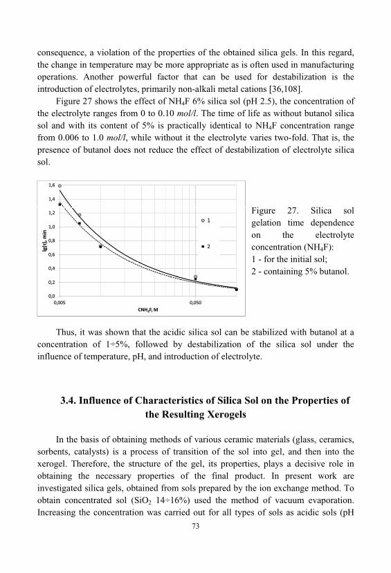
73
consequence, a violation of the properties of the obtained silica gels. In this regard, the change in temperature may be more appropriate as is often used in manufacturingoperations. Another powerful factor that can be used for destabilization is theintroduction of electrolytes, primarily non-alkali metal cations [36,108].
Figure 27 shows the effect of NH4F 6% silica sol (pH 2.5), the concentration ofthe electrolyte ranges from 0 to 0.10 mol/l. The time of life as without butanol silicasol and with its content of 5% is practically identical to NH4F concentration rangefrom 0.006 to 1.0 mol/l, while without it the electrolyte varies two-fold. That is, thepresence of butanol does not reduce the effect of destabilization of electrolyte silicasol.
Figure 27. Silica solgelation time dependenceon the electrolyteconcentration (NH4F): 1 - for the initial sol; 2 - containing 5% butanol.
Thus, it was shown that the acidic silica sol can be stabilized with butanol at aconcentration of 1÷5%, followed by destabilization of the silica sol under theinfluence of temperature, pH, and introduction of electrolyte.
3.4. Influence of Characteristics of Silica Sol on the Properties ofthe Resulting Xerogels
In the basis of obtaining methods of various ceramic materials (glass, ceramics, sorbents, catalysts) is a process of transition of the sol into gel, and then into thexerogel. Therefore, the structure of the gel, its properties, plays a decisive role inobtaining the necessary properties of the final product. In present work areinvestigated silica gels, obtained from sols prepared by the ion exchange method. Toobtain concentrated sol (SiO2 14÷16%) used the method of vacuum evaporation. Increasing the concentration was carried out for all types of sols as acidic sols (pH
74
2.5) and sols stabilized with ions of Na+ (pH 8.5). To obtain gels, sols were kept atroom temperature in closed jars to form a gel, and then were subjected to drying at t =120 for 12÷13 hours. For comparison investigated gels prepared from acid andalkaline sols and sols containing additives of butanol.
To estimate the specific surface area of the sols and silica xerogels were used themethod of potentiometric titration, developed by Sears [25]. The porosity of the silicagels was controlled by mercury porosimetry and pycnometrically. Determinationresults of specific surface and pore structure of the samples showed the followingvalues. The values of the specific surface of initial silica sol with a pH of 2.5 and 8.5respectively equal 1088 m2/g and 774 m2/g. Decrease in the specific surface area withincreasing pH due to acceleration of the polycondensation process of polysilicic acidsand accordingly increasing the size of the colloidal particles.
Specific surface xerogels significantly less than the initial sol: 40% in the acidsol and 60% in the alkaline sol. This may be due to the growth of the colloidalparticles and the occurrence of bridging contacts between the particles. Thus, samplesobtained from the acid sol, have a microporous structure, and increasing pH of the solcontributes to the development macroporous structure obtained xerogels.
Mercury porosimetry data, however, do not allow determining thecharacteristics in microporous samples.
Texture of xerogels depends not only on the pH and the time of thepolycondensation reaction, but the composition of the liquid phase. As mentionedabove, additives butanol in acid sol have a stabilizing effect on it, in turn, to an alkalisol reverse effect is observed, it gelation time decreases due to compression of theelectric double layer.
We have found that the specific surface of the xerogels obtained from acid solswith butanol to 20% less, compared with the specimens obtained without the additionof alcohol. For the samples obtained from the alkaline sols, the effect is somewhatless (10%). In both cases there is a decrease in the specific surface area, particlegrowth and increased porosity of the samples, respectively, due to the increase in thetime and the reaction rate of polycondensation of silicic acid.
Thus, research has shown that adjusting the pH and accordingly the reactiontime of the polycondensation, as well as the composition of the liquid phase can beobtained xerogels with different characteristics of the porous structure.
75
4. SIMULATION OF HARDENING PROCESSES, INSILICATE SYSTEMS
4.1. Quasi-homogeneous Approximation to Describe theProperties of Disperse Systems
Lots of real systems are distinguished by extremely irregular geometricstructure, which is characterized by a wide range of spatial scales. These systemsinclude - various aerosols, colloidal solutions, suspensions, gas suspension, emulsion, bubble layers, composite materials and porous layers of catalysts, nanocomposites, etc.
Heterogeneity (structural levels) in these systems differs considerably in order ofmagnitude. For example, in a reactor with a fixed catalyst bed can distinguish at leastthree characteristic spatial scales: the height of the layer, radius of the grain, theradius of the pores. Determinations of rates of the individual stages of the processobserved in such systems are often carried out in the framework of the so-calledquasi-homogeneous approximation. It is based on the representation of theinhomogeneous system as a combination of interpenetrating and interactingcontinuums with effective distributed parameters. Such a representation can be donephenomenologically, based on empirical laws (such as Darcy's law for the filteringprocess) [307].
Another variant of approach is a hierarchical model building, and is associatedwith a serial and independent consideration of the process on each of the structurallevels. Irregular geometric structure of the space causes a random (fluctuating) thenature of the distribution of temperature, concentrations, reactant streams etc.. Moreover, the range of spatial scales of the fluctuations of the parameters correlatedwith the spectrum of the characteristic spatial scale of the system. For example, in thecase of heterogeneous catalytic reactions, the reactants flows fluctuate on the scale ofgrain radius due to the random orientation of the pores in the catalyst grains, on thescale of, the pore radius respectively - because the gas filtering features in the spaces
76
between adjacent grains on scale of altitude layer - due to accidental nature of thepacking of grains in the layer [308].
With the hierarchical construction of quasi-homogeneous approximation, produce operation averaging (smoothing) fluctuations of the order, it whichcorrespond to the previous small-scale structural level. To do this it is necessary thatthe characteristic scale of the previous level l was much smaller than thecharacteristic scale L next level, and the system comprises at the level L, macroscopically large number of irregularities of scale l. In addition, there must be anintermediate size (l << << L) such that after averaging over the volume ~ 3 (orsurface ~ 2) measured parameters , presented not fluctuating, and regular functionsof the spatial coordinates, the characteristic scale of changes L. Scale has the valueat which it is much longer than the characteristic distance over which interactfluctuations of scale l and is called the correlation radius. Averaging area of size iscalled an elementary physical volume or macropoint [306]. For example, thechemical absorption process of gas by liquid in two-phase bubble type reactor, lcorresponds to the scale of a gas bubble, a L - reactor size.
Averaging concentrations of the components in each phase is carried out byelementary volume 3, containing a sufficiently large number of bubbles, butsignificantly inferior to the reactor volume. Linear dimension is chosen taking intoaccount the intensity of the local hydrodynamic mixing. Volume 3 regarded asmacropoint with efficient (i.e., averaged over the observation time) values of masstransfer coefficients, specific heat release, the distribution of substances between thephases, etc. These parameters are required for the compilation of kinetic equations ofindividual stages. Then make up the balance equations of mass and energy, takinginto account mixing, at a scale of the entire reactor.
In describing the processes in porous materials with liquid or gaseous substancesor immiscible liquids, the researchers successfully used a hierarchical approach withthe operation of averaging. An example of this approach is to describe the processessuch as gas-phase reactions on supported liquid catalysts, catalytic hydrogenation andoxidation of liquid hydrocarbons, electrochemical decomposition of the liquidreactants with the evolution of gaseous products, and drying the impregnated porousmaterials a multiphase filtering. Under this approach, it was possible to calculate thecoefficients of the effective component transport in the porous material, and explainmany experimental effects, e.g., removal of the dissolved components on the outersurface, and in macropores during the drying process [309].
Quasi-homogeneous approximation may not be applicable in the study ofmacrokinetics, of disordered systems, with a wide range of spatial scales, if thecorrelation radius of the fluctuations, the order of magnitude is comparable to the sizeof the system L. Such a situation may arise, for example, in chemical reactions in
77
turbulent flow, in a bubbling, and developed fluidized layers. , , ,
. Also, similar situations occur when multiphaseprocesses in porous media, ion exchange membranes and others. First of all, reliableexperimental criterion, indicating the presence of large-scale fluctuations, is theemergence of dependence of effective empirical constants on the system size L, instudies of various systems and processes. This phenomenon is observed for theinterfacial exchange coefficients and longitudinal diffusion, for fluidized andbubbling layers [310].
For quantitative analysis of strongly fluctuating systems are promising methodsdeveloped in the theory of phase transitions of the second kind, and in the study ofcritical phenomena. In these systems, near the critical point there are strongfluctuations of the order parameters. In these systems, in the vicinity of the criticalpoint, the experimentally are observed strong fluctuations of the order parameters.
In this paper, we tried to apply the approach quasi-homogeneous approximationto describe the behavior of colloidal solutions such as silica sol. We emphasize thatthis approach is approximate and may give some deviations in the evaluation ofcertain parameters. This is due primarily to the nature of the scaling, and the degreeof averaging fluctuations. Also in this method, there are limitations on the number ofparameters used, which also contributes to the restriction of accuracy of the estimateof design parameters. However, this method gives a fairly accurate assessment of thedirection and nature of the influence of various factors on the properties of thestudied systems.
4.2. Statistical Polymer Method. Main Notions, Definitions andEquations
Theoretical description of branched crosslinked polymers, gels and aggregatesformed in random processes was traditionally very problematic for polymer scienceand related disciplines because of difficulties of taking into account all possiblestructures. Classic methods elaborated by Flory for linear macromolecules [312] arenot applicable, in most cases, to branched, especially crosslinked structures [313]. Moreover, if systems of branched crosslinked polymers are in non-equilibrium, theirdescription is impossible without combination of special statistical methods[168,314] and non-linear dynamics of chaos [315].
The problem of modeling of branched cross-linked macromolecules andaggregates was solved recently by the statistical polymer method [168,314].
78
Let us consider the statistical polymer method in the following order:(I) modeling of separate macromolecules without crosslinking; (2) modeling of equilibrium polymeric systems, evaluation of thermodynamic
functions, first of all chemical potential;(3) modeling of complex systems (crosslinking and/or non-equilibrium state,
etc.);(4) possible applications. Statistical Polymer. Statistical N-mer is defined as the averaged structure
formed by all possible structures of N-mers and exhibiting all possible structuresofpolymers containing the same number of monomeric units. In the light of thisdefinition, polymeric systems are considered as sets of assemblages possessingstructures averaged on all polymers containing the same numbers of monomeric units- statistical polymers. All interactions in polymeric systems are considered as resultof interactions of statistical polymers, and the evaluation of additive (extensive)parameters like energy, entropy etc. may be carried out through statistical polymersinstead of branched crosslinked ones.
For large values of A, the number of possible structures is, obviously, muchmore than the number of monomeric units through the system, and most of thepossible structures cannot realize, that could seem to be a drawback of the statisticalpolymer method. However, if the relaxation time of reactions is much shorter than themeasurement duration, one may assume the dynamic equilibrium between variousstructures that determines correctness of the statistical polymer method even for largeenough N. Moreover, because of quantum effects the traditional description ofmacromolecules (as specified structures) is not exact, and this factor of eventual errorcaused by quantum features of the system allows application of the statisticalpolymer method for very large macromolecules.
Now, let us consider characteristics of statistical polymer which determine itsability to interact with other statistical polymers and monomers.
Vacancy of the statistical polymer is defined as the capacity of the statisticalpolymer to capture a monomeric unit. The number of vacancies is denoted as V(N). Itis obvious that the capture of an additional monomeric unit by statistical N-mer leadsto the formation of (N + 1)-mer.
Extreme unit of the statistical polymer is defined as the monomeric unit whichhas one only bond with the main structure of the statistical polymer. Let us denote thenumber of extreme units in statistical N-mer as U(N). It is obvious that breaking ofthe bond of the extreme unit with the main structure of statistical N-mer leads to theformation of (N-1)-mer.
Processes of polymerization-destruction in a polymeric system are described ascombinations of reactions of statistical polymers:
79
(4.1)
(4.2)where Pol(N) is the statistical polymer containing N units; M is a monomer.
Since reactions (4.2), in their turn, can be written as combinations of reactions (4.1), these can be considered as independent reactions. Since the process of polymerizationis determined by vacancies, whereas destruction - by extreme units, reactions (4.1)can be written in the following form:
(4.3)where Ex is the extreme unit. If no crosslink forms, the values of V(N), U(N) are
given by the following recurrent equations [314]:
(4.4)
(4.5)where m is the maximal number of possible branches (functionality minus one). The kinetics of independent reactions like (4.1) is given by
(4.6)where W+, W , and K+, are the rates and the rates constants of the direct and the
inverse reactions, respectively, and CN is the concentration (mole fraction) of the N-mer. For equilibrium,
(4.7)
(4.8)
(4.9)
80
(4.10)where T - Temperature, R - gas constant;
and
(4.11)For large values of N, one obtains
, (for M=1, m>1)
(4.12)
(4.13)The statistical polymer method can be employed also for the description of
multicomponent systems, the relevant equations are derived in [168].
4.3. Crosslink Formation
Let us consider crosslink as the bond between two monomeric units inside thesame macromolecule. Hence, crosslink can form only between monomeric unitspossessing vacancies. Each vacancy can participate in the formation of crosslink withmonomeric units which possess vacancies. Hence, the sum number of possibilities ofring formation is
(4.14)where B0(N) is the number of monomeric units which have no vacancies. The
value of B0(N) can be estimated from
(4.15)
taking into account that for monomeric units with s vacancies :
81
(4.16)
(4.17)The rate of reaction of crosslink formation is
(4.18)The rate of reaction of crosslink destruction is
(4.19)where Gr(N) is the number of crosslinks, whereas Kc+ and Kc are the constants
of crosslink formation and destruction, respectively. In equilibrium:
(4.20)
(4.21)The crosslink formation reduces the number of vacancies and extreme units:
(4.22)
(4.23)or
(4.24)where index “0” means the non-crosslinked state, l - the number of crosslinks. The ring formation reduces both the number of vacancies and that of extreme
units, therefore one may assume that the weak ring formation does not significantlyinfluence the weight distribution of polymers.
82
4.4. Thermodynamic Functions of Non-Crosslinked StatisticalPolimers. Non-Equilibrium
From Eq. (4.10) one obtains
(4.25)However, the heat effect of a reaction of polymerization
(4.26)where is the energy of a vacancy (all vacancies are assumed to be
equivalent!). From Eqs. (4.25) and (4.26) one obtains
(4.27)However
(4.28)Taking into account that , and [314], one obtains
(4.29)
(4.30)The chemical potential of statistical N-mer is given by
(4.31)where CN is the concentration of N-mer; - the entropy of monomer. Now, let us consider a non-equilibrium chemical process in a polymeric system
described in linear approximation:
83
(4.32)where indexes “1” and “2” correspond to the initial and final states, respectively.
The Gibbs’ energy in these states is given by
(4.33)
(4.34)The moving force of the process (32) is
(4.35)where . Description of non-linear situations can be carried out in the same style, using
methods of dynamic of chaos [315].
4.5. Combination of the Statistical Polymer and Fractal Methods
Let us consider statistical N-mer ( ) as the fractal with dimensionality Df . Such approach can be compared to the accepted practice of the construction of fractalclusters by the Monte-Carlo method of random addition of new units; only difference- the statistical polymer is automatically random and contains all possible structuresof randomly constructed clusters (of course, if they contain the same number A ofunits). We may assume that the statistical N-mer can be considered as the averagedstructure obtained after the infinite number of operations of constructions of N-mericclusters.
We note some obvious advantages of the statistical polymer approach incomparison with the Monte-Carlo method of the construction of cluster: (1) Monte-Carlo method is not strictly random, that causes several errors which are reduced anddisappear only for -meric clusters; (2) the application of the Monte-Carlo method tothe 3-dimensional systems is too difficult, whereas the statistical polymer method is
84
applicable in all situations, that offers much more freedom to the researcher; (3) theMonte-Carlo method furnishes numerical results, whereas the statistical polymermethod allows the obtainment of analytical ones (at least, for all additive parametersof macromolecules and polymeric systems); (4) for the obtainment of the same result, the Monte-Carlo method requires much more calculations.
Since we consider statistical N-mers (at very large N) as random fractal-likeobjects, we need to define the characteristic dimension (size) of the fractal statisticalpolymer. Let us define the characteristic size of fractal statistical N-mer (at very largeN) as follows:
(4.36)
where d0 is the characteristic size of monomeric unit ( , 0 is the
volume of monomer unit), and the parameter Rk(N) (presence) characterizes thedistribution of monomeric units inside the statis- deal polymer [314]. Since thevalidity of the fractal approach is assumed, the volume and the surface area of suchN-mer are given by
(4.37)
(4.38)where Df is the fractal dimensionality. On the other hand, the same parameters are easily estimated from the total
number of monomeric units:
(4.39)
(4.40)where a0 is the surface area per monomeric unit, and as a normalization
coefficient. According to assumptions made above, Eqs. (4.36)-(4.38) should be correct at
very large N, while for low and moderate values of N, they should not. This meansthat the total divergence between the values obtained from Eqs. (4.37)-(4.40) is large
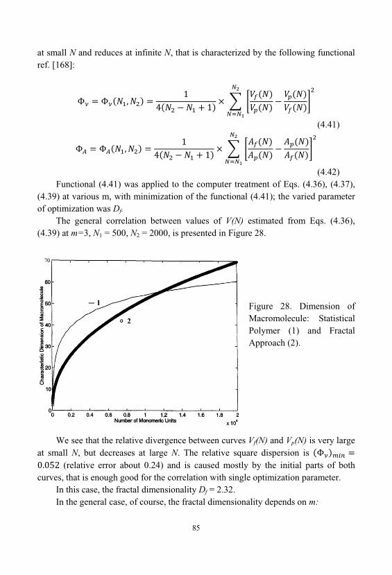
85
at small N and reduces at infinite N, that is characterized by the following functionalref. [168]:
(4.41)
(4.42)Functional (4.41) was applied to the computer treatment of Eqs. (4.36), (4.37),
(4.39) at various m, with minimization of the functional (4.41); the varied parameterof optimization was Df.
The general correlation between values of V(N) estimated from Eqs. (4.36), (4.39) at m=3, N1 = 500, N2 = 2000, is presented in Figure 28.
Figure 28. Dimension ofMacromolecule: StatisticalPolymer (1) and FractalApproach (2).
We see that the relative divergence between curves Vf(N) and Vp(N) is very largeat small N, but decreases at large N. The relative square dispersion is
(relative error about 0.24) and is caused mostly by the initial parts of bothcurves, that is enough good for the correlation with single optimization parameter.
In this case, the fractal dimensionality Df = 2.32. In the general case, of course, the fractal dimensionality depends on m:
86
APPLICABILITY OF THE STATISTICAL POLYMER METHOD. Thestatistical polymer method allows modeling of not only polymers but also gels, several composites, associates in polar liquids, etc.
The combined fractal- statistical polymer method is applicable to all objectsdescribed by fractal theory, first of all random fractals.
The statistical polymer method can be very effective for the solution ofnumerous problems of materials science, because many of widespread materialsexhibit macromolecule-like fragments. However, in such cases one should take intoaccount that there are two kinds of interactions: inside macromolecule-like fragments(“strong” interactions) and between them (“weak” internetions). “Weak” interactionsdetermine first of all mechanical stability, permeability and sometimes adhesionproperties of the material.
The statistical polymer method is based on the consideration of averagedstructures of all possible macromolecules of the same weight. One has derivedequations allowing evaluation of all additive parameters of macromolecules and theirsystems. The statistical polymer method allows modeling of branched crosslinkedmacromolecules and their systems in equilibrium or non-equilibrium. The fractalconsideration of statistical polymer allows modeling of all kinds of random fractaland other objects studied by fractal theory. The statistical polymer method isapplicable not only to polymers but also composites, gels, asso- dates in polar liquidsand other aggregates.
4.6. Description of the State of Colloidal Solutions of Silicon Oxidefrom the Viewpoint of Statistical Physics.
This section is based on the idea lies in the fact that a colloidal solution of silica- silica sol consists of a very large number of interacting with each other particles thatare in continuous motion.
It is devoted to the study of an idealized system of colliding, but non-interactingparticles of sol. To simplify the approach, consider the ideal system of monodispersecolloidal particles. Since the sol particles much larger than the molecules of thesolvent in which they are located, their interactions with solvent molecules can beneglected and consider this system as a suspension of the sol particles in a certain
87
continuous environment - continuum. Sol particles most of the time are runningfreely and do not collide with each other. They interact only during collisions, causing the speed and direction of movement, each of the colliding particles varies. Therefore, trajectory of motion of particles in the sol is a broken line.
With certain assumptions, the ideal gas laws can be applied to such a system. Consider a system of N particles filling a certain volume of space V. The distributionof particles in space is described by the function:
(4.1)(4.43)depending on the time and coordinates. This function is called countable
concentration and is defined as follows. We partition the space filled with solparticles, into small pieces and look at one of these parts, the volume of which wedenote by dV. Volume dV called physically infinitely small if the number of dN ofparticles therein substantially smaller than the total number N of particles in volumeV, but in this case, many times greater than unity: . The position ofvolume dV in space can be set using the radius vector one of its points. The rationumber dN of particles in the volume dV to the value of this volume, called acountable particle concentration, in the area of space:
(4.2) (4.44)Since in its motion particles can enter into the volume dV and out of it, the
number of particles dN, in this volume, strictly speaking, will change over time. Therefore, the concentration is a function not only of the radius vector , but also thetime t. By integrating the equation (4.2) (4.44), we obtain the number N, equal to thenumber of particles in the volume V:
(4.3)(4.45)When the particles are distributed throughout the volume of the vessel, on
average uniformly whilst their concentration everywhere is identical, and equation(4.3)(4.45) becomes:
(4.4)(4.46)
88
The physical meaning of countable concentration can be defined as the numberof particles per unit volume. In fact, putting V = 1 m3, we obtain Cn=N.
Let us consider the probability that a randomly selected one of sol particle intime t will be in a volume dV:
(4.5)(4.47)Thus it is possible to get a value of the probability density:
(4.6)(4.48)Probability density, also called the distribution function, of the sol particles in
space. This function is related to the countable concentration of sol, the followingsimple equation:
(4.7)(4.49)For the case of monodisperse particles, can can obtain the equation for the mass
concentration of particles in a unit volume of sol:
(4.8)(4.50)Where: mp - the mass of one particle of sol. For the spherical sol particles with a
diameter Dp, when of sol substance density , it is equal to:
(4.9.)(4.51)In the case of polydisperse systems, it is necessary to introduce a new function
for a countable concentration which also depends on the mass of particles of the
appropriate size - . Accordingly, the expression for the mass
concentration will be:
(4.10)(4.52)
89
Where: - distribution function of particle mass in the sol. However, to
simplify the description and analysis of the system of the sol particles we consider thesimplified case of a monodisperse of sol.
To describe the microscopic state of the sol, we use the function:
(4.11)(4.53)This function depends on the time t, the radius vector and the speed vector ,
and called the distribution function. It is defined as follows. Let us consider a particlethat at time t were in the volume dV at the radius vector . The number of suchparticles is - dN. The movement of each particle is characterized by a certain speedvector , where i - number of the particle.
We construct an imaginary rectangular coordinate system, on the axes of whichwe plot the values of projections , and of the velocity vector of each particle
in this volume. Space formed by using this coordinate system, called the space ofvelocities. Single out small volume in the velocity space, which is physicallyinfinitesimal, the value of this volume is denoted . Speed of some particles fromthe dN end in this volume: . Let their number be dN'. And this valuesatisfies the inequalities . The distribution function (4.11)(4.53) isdefined as the ratio of the number of particles dN', to the product of volumes of dVand :
(4.12)(4.54)From this definition it follows that the number of particles dN', which at time t,
appeared in volume dV, with the radius vector , and their velocity vectors ending inthe volume of , with the vector , can be calculated if we know the distributionfunction (4.11)(4.53). Separating the variables and integrating the equation(4.12)(4.54) in terms of volume, and then dividing it by dV, and considering that theintegration is performed over the velocity space, we obtain the equation:
(4.13)(4.55)This equation relates the concentration of the particles and their distribution
function. The value of the elementary volume in velocity space can be
90
represented as the product of differentials of the projections of the velocity vectoron the coordinate axes, which makes the integral (4.13)(4.55) in the triple integral:
(4.14)(4.56)Where: integration is performed over all possible values of variables , and
. According to the definition (4.5)(4.47), we can determine the probability that
one randomly selected particle of the sol at time t stored in the volume dV, and itsvelocity - in the volume of space velocity. The corresponding probability densityis defined as the ratio
(4.15)(4.57)As follows from formula (4.12)(4.54), the probability density associated with
the distribution function (4.11)(4.53) by the relation
(4.16)(4.58)Particle velocity distribution is isotropic, if the distribution function depends
only on the modulus of the velocity vector , and does not depend on its direction:. With such velocity distribution of particles, the particle fluxes moving
in different directions are the same. In other words, all the directions of particlemotion in the space are equal. In this case, the average velocity of the directed motionof the particles obviously must be equal to zero: . This means that the directionof motion of the particles is absent. This situation is typical in cases where the systemdoes when mixing and sol particles are small enough, and the effect of sedimentationof particles under the influence of gravity can be neglected.
An important factor in determining the behavior of the sol is the averagevelocity of the of the sol particles. To determine them, we assume that dN is thenumber of particles in the volume dV. We find the average value of module ofvelocity vector of particles. For this purpose, it is necessary to sum the modules ofvelocities of particles in a volume dV, and the resulting sum divide into the numberof particles:
91
(4.17)(4.59)where the index i denotes the number of particles in a volume dV. As the
volume of in velocity space sufficiently small for those particles whose velocity, end up in this volume, we can put with , where - arbitrary vectorending in volume . Therefore, the sum of modules velocities of the particles isequal to the product of the module velocity of one particle on the number dN':
(4.18)(4.59)Sum of modules velocities of all particles in the volume dV will be equal to the
integral over velocity space of this expression:
(4.19)(4.60)Substituting of this sum in (4.17)(4.59) with (4.2)(4.44) yields
(4.20)(4.60)Actually, this equation represents the moment of the 1st order of the function of
three-dimensional probability distributions. Similarly, we can derive formulas for themoments of other orders of the probability distribution function. For example, the
mean values of and of the velocity vector and the square of its module, we havethe following formulas
(4.21)(4.61)
(4.22)(4.62)In the general case, the vector average particle velocity is not zero and is a
function of time and the radius vector. This means that at any given time in a givenplace of space, the whole weight of the sol, as a whole moves in a certain direction. Figuratively speaking, sol flows along the guide, or it is stirred in the reaction vessel.
92
In solving some problems it is convenient to assume that the sol particles areinvolved in two movements: the random thermal motion and direction of motion, which is characterized by a vector of average speed .
Note that the integration in (4.20)(4.60)-(4.22)(4.62) is performed over the spaceof velocities for given values of t and . Therefore, the expressions obtained afterintegration generally will represent some functions of the time and the coordinates.
Value
(4.23)(4.63)called the mean square velocity of the particle.
4.7. Analysis of the Behavior of Silica Sol, in Terms of Maxwell-Boltzmann Distribution
Let us consider silica sol, which is in a state of thermodynamic quasi-equilibrium. Function (4.11), which describes the distribution of the sol particles inspace and velocity, can be found using the Gibbs canonical distribution. For thisshould be considered a colloidal solution, as an ensemble, each of sol particles, it isone of the systems. The parameter in the canonical Gibbs distribution, should beunderstood as an aggregate of the spatial coordinates x, , z, and projections vx, vy, vz
of the velocity vector of the particle:
According to the law Gibbs probability density for a particle in the ideal gasapproximation for a system in a state of thermodynamic equilibrium or near-equilibrium state will have the form
(4.24)(4.63)Where - the inverse temperature, and
(4.25)(4.64)
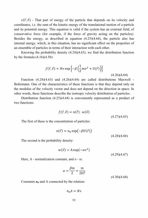
93
- That part of energy of the particle that depends on its velocity andcoordinates, i.e. the sum of the kinetic energy of the translational motion of a particleand its potential energy. This equation is valid if the system has an external field, ofconservative force (for example, if the force of gravity acting on the particles). Besides the energy, as described in equation (4.25)(4.64), the particle also hasinternal energy, which, in this situation, has no significant effect on the properties ofan ensemble of particles in terms of their interaction with each other.
Knowing the probability density (4.24)(4.63), we find the distribution functionby the formula (4.16)(4.58):
(4.26)(4.64)Function (4.24)(4.63) and (4.26)(4.64) are called distributions Maxwell -
Boltzmann. One of the characteristics of these functions is that they depend only onthe modulus of the velocity vector and does not depend on the direction in space. Inother words, these functions describe the isotropic velocity distribution of particles.
Distribution function (4.25)(4.64) is conveniently represented as a product oftwo functions:
(4.27)(4.65)The first of these is the concentration of particles:
(4.28)(4.66)The second is the probability density:
(4.29)(4.67)Here, A - normalization constant, and - is:
(4.30)(4.68)Constants n0 and A connected by the relation:
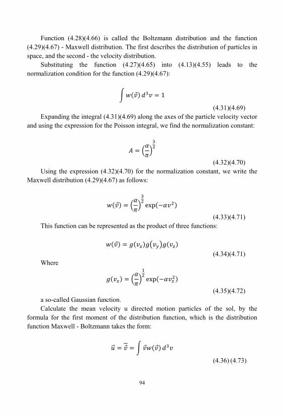
94
Function (4.28)(4.66) is called the Boltzmann distribution and the function(4.29)(4.67) - Maxwell distribution. The first describes the distribution of particles inspace, and the second - the velocity distribution.
Substituting the function (4.27)(4.65) into (4.13)(4.55) leads to thenormalization condition for the function (4.29)(4.67):
(4.31)(4.69)Expanding the integral (4.31)(4.69) along the axes of the particle velocity vector
and using the expression for the Poisson integral, we find the normalization constant:
(4.32)(4.70)Using the expression (4.32)(4.70) for the normalization constant, we write the
Maxwell distribution (4.29)(4.67) as follows:
(4.33)(4.71)This function can be represented as the product of three functions:
(4.34)(4.71)Where
(4.35)(4.72)a so-called Gaussian function. Calculate the mean velocity u directed motion particles of the sol, by the
formula for the first moment of the distribution function, which is the distributionfunction Maxwell - Boltzmann takes the form:
(4.36) (4.73)
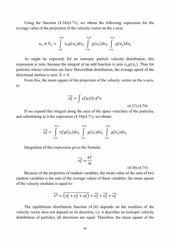
95
Using the function (4.34)(4.71), we obtain the following expression for theaverage value of the projection of the velocity vector on the x-axis:
As might be expected, for an isotropic particle velocity distribution, thisexpression is zero, because the integral of an odd function is zero . Thus forparticles whose velocities are have Maxwellian distribution, the average speed of thedirectional motion is zero: .
From this, the mean square of the projection of the velocity vector on the x-axis, is:
(4.37) (4.74)If we expand this integral along the axes of the space velocities of the particles,
and substituting in it the expression (4.34)(4.71), we obtain:
Integration of this expression gives the formula:
(4.38) (4.75)Because of the properties of random variables, the mean value of the sum of two
random variables is the sum of the average values of these variables; the mean squareof the velocity modulus is equal to:
The equilibrium distribution function (4.26) depends on the modulus of thevelocity vector does not depend on its direction, i.e. it describes an isotropic velocitydistribution of particles, all directions are equal. Therefore, the mean square of the
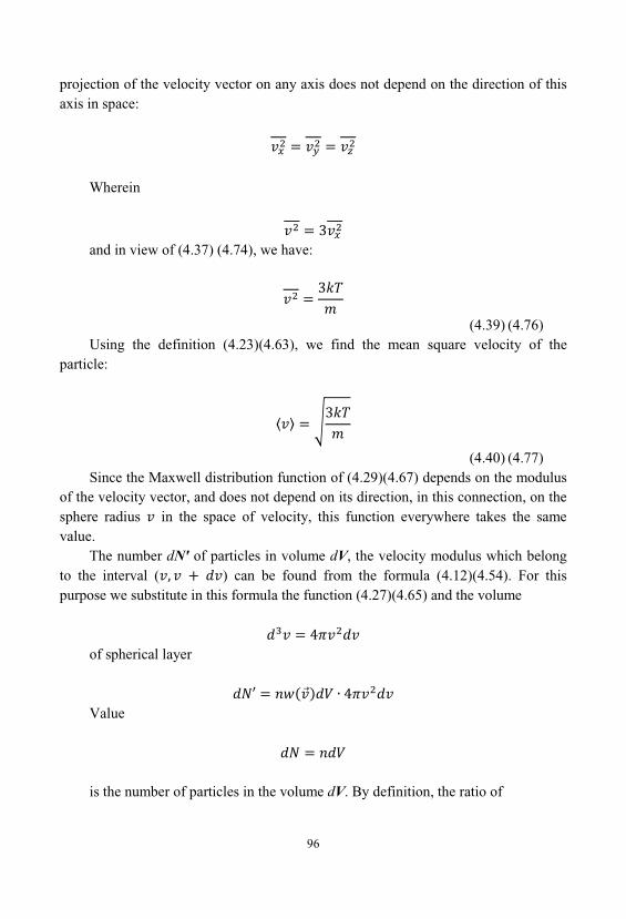
96
projection of the velocity vector on any axis does not depend on the direction of thisaxis in space:
Wherein
and in view of (4.37) (4.74), we have:
(4.39) (4.76)Using the definition (4.23)(4.63), we find the mean square velocity of the
particle:
(4.40) (4.77)Since the Maxwell distribution function of (4.29)(4.67) depends on the modulus
of the velocity vector, and does not depend on its direction, in this connection, on thesphere radius in the space of velocity, this function everywhere takes the samevalue.
The number dN' of particles in volume dV, the velocity modulus which belongto the interval ( ) can be found from the formula (4.12)(4.54). For thispurpose we substitute in this formula the function (4.27)(4.65) and the volume
of spherical layer
Value
is the number of particles in the volume dV. By definition, the ratio of
97
there is a possibility that one of the particles has a velocity whose modulus is inthe range from to .
We introduce the function , depending on the modulus of the vectorvelocity by the relation
(4.41) (4.78)
Using the expression (4.34), we have
(4.42) (4.79)Equation (4.42) is called, the Maxwell function. For , the function (4.42)
(4.79) is equal to zero: . If the value of speed module, which is called themost probable velocity of the particle, Maxwell functions has a maximum. In theinterval it is monotonically increasing, and in the interval it ismonotone decreasing, tends to zero as .
Because the expression represents the probability respectively integralof this expression is equal to one:
(4.43) (4.80)The physical meaning of the function Maxwell relations for sol can be explained
as follows. According to the definition of probability expression is thefraction of particles, modules velocities are in the range of The relativenumber of particles whose velocities are in the range of to v_ , will be expressedby the integral
98
where N - the total number of particles considered, - number ofparticles, modules velocities are in the range . Let us find the most probablevelocity of the particles. The necessary condition for an extremum function, thederivative of for this value is zero. Equating to zero the derivative withrespect to the parameter , from the expression (4.42) (4.79) we find required valueof the most probable velocity of the particles, which is equal to:
(4.44) (4.81)Substituting this value into the formula (4.42) (4.79), we obtain the maximum
value of the Maxwell function
(4.45) (4.82)Maxwell function (4.42) (4.79) contains as a parameter value , which
according to formula (4.30)(4.68) depends on the temperature of the sol. Therefore, the Maxwell function change when there is a change in temperature of the sol. Thesame is a change in the particle velocity distribution. The most probable velocity ofparticles (4.43) (4.80) increases with increasing temperature. Thus, the maximumvalue of the Maxwell function (4.45) (4.82) decreases with an increasing temperature. The form of the graphic depending of the Maxwell function with increasingtemperature is altered so that the maximum of the curve shifts to the right (towardshigh velocities) and becomes lower, but the area under the curve, however, remainsequal to unity.
We will analyze how changes with temperature, the particle velocitydistribution. For this purpose we choose some arbitrary value of velocity . Therelative number of particles and at speeds respectively, smaller and larger than , expressed by integrals of Maxwell functions:
(4.46) (4.83)and
99
(4.47) (4.84)It is easy to see that with increase in temperature the amount of
particles with velocities monotonically decreases, and the amount ofparticles with velocities increases. This property is allows us to calculate the number of particles with velocities
above a certain level, and thus determine the number of particles that are able tointeract with each other or with other objects if necessary to overcome some potentialbarriers.
4.8. The Mean Free Path of the Colloidal Particles
Colloidal particles in a solution are in continuous motion. Consider firstapproximation model colloidal particle motion in the approximation of an ideal gas. We believe that the solvent is a continuum, does not affect the nature of theinteraction between the particles. The particles can be represented in the form ofsmall solid elastic spheres of diameter d, the collision of which there is no interaction. The entire system is also represented in the form of an infinitely large vessel, thewalls of which have no effect on the behavior of colloidal particles in the system. Allparticles in the system have the same size.
Each particle moves uniformly and rectilinearly, as long as does not collide withany other particle. As a result of the collision, the particle abruptly changes itsdirection of motion, and then again moves in a straight line at a constant speed untilthe next collision.
Using this model, we calculate the average time between two successivecollisions of one arbitrarily selected particle with other particles of the colloidalsolution. Selected particle collision with another particle will occur only when centerof the particle, would be at the moment of convergence between the particles at adistance from the line of movement of the first particle less than particle diameter d(Figure 29). Therefore, the centers of all the particles encountered on line trajectoryselected particle, for some time t, and forcing it to change its direction of motionturns out at the appropriate time, inside a cylinder of radius , whose axis is thetrajectory of considered particle. Of course, this model is meaningful only in the casewhen the average mean free path of particle , is much greater than its diameter:
.
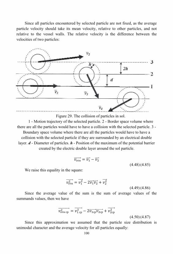
100
Since all particles encountered by selected particle are not fixed, as the averageparticle velocity should take its mean velocity, relative to other particles, and notrelative to the vessel walls. The relative velocity is the difference between thevelocities of two particles:
Figure 29. The collision of particles in sol. 1 - Motion trajectory of the selected particle. 2 - Border space volume where
there are all the particles would have to have a collision with the selected particle. 3 -Boundary space volume where there are all the particles would have to have a
collision with the selected particle if they are surrounded by an electrical doublelayer. d - Diameter of particles. h - Position of the maximum of the potential barrier
created by the electric double layer around the sol particle.
(4.48) (4.85)We raise this equality in the square:
(4.49) (4.86)Since the average value of the sum is the sum of average values of the
summands values, then we have
(4.50) (4.87)Since this approximation we assumed that the particle size distribution is
unimodal character and the average velocity for all particles equally:
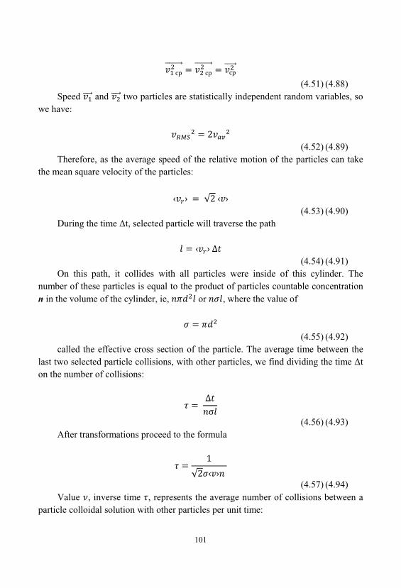
101
(4.51) (4.88)Speed and two particles are statistically independent random variables, so
we have:
(4.52) (4.89)Therefore, as the average speed of the relative motion of the particles can take
the mean square velocity of the particles:
(4.53) (4.90)During the time t, selected particle will traverse the path
(4.54) (4.91)On this path, it collides with all particles were inside of this cylinder. The
number of these particles is equal to the product of particles countable concentrationn in the volume of the cylinder, ie, or , where the value of
(4.55) (4.92)called the effective cross section of the particle. The average time between the
last two selected particle collisions, with other particles, we find dividing the time ton the number of collisions:
(4.56) (4.93)After transformations proceed to the formula
(4.57) (4.94)Value , inverse time , represents the average number of collisions between a
particle colloidal solution with other particles per unit time:
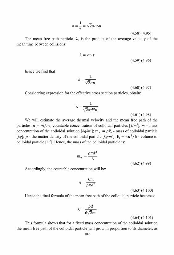
102
(4.58) (4.95)The mean free path particles , is the product of the average velocity of the
mean time between collisions:
(4.59) (4.96)
hence we find that
(4.60) (4.97)Considering expression for the effective cross section particles, obtain:
(4.61) (4.98)We will estimate the average thermal velocity and the mean free path of the
particles. countable concentration of colloidal particles [1/m3]; m – massconcentration of the colloidal solution [kg/m3]; - mass of colloidal particle[kg]; - the matter density of the colloidal particle [kg/m3]; - volume ofcolloidal particle [m3]. Hence, the mass of the colloidal particle is:
(4.62) (4.99)Accordingly, the countable concentration will be:
(4.63) (4.100)Hence the final formula of the mean free path of the colloidal particle becomes:
(4.64) (4.101)This formula shows that for a fixed mass concentration of the colloidal solution
the mean free path of the colloidal particle will grow in proportion to its diameter, as
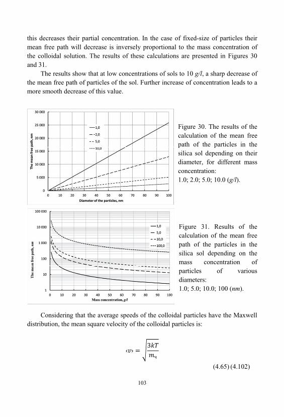
103
this decreases their partial concentration. In the case of fixed-size of particles theirmean free path will decrease is inversely proportional to the mass concentration ofthe colloidal solution. The results of these calculations are presented in Figures 30and 31.
The results show that at low concentrations of sols to 10 g/l, a sharp decrease ofthe mean free path of particles of the sol. Further increase of concentration leads to amore smooth decrease of this value.
Figure 30. The results of thecalculation of the mean freepath of the particles in thesilica sol depending on theirdiameter, for different massconcentration:1.0; 2.0; 5.0; 10.0 (g/l).
Figure 31. Results of thecalculation of the mean freepath of the particles in thesilica sol depending on themass concentration ofparticles of variousdiameters:1.0; 5.0; 10.0; 100 (nm).
Considering that the average speeds of the colloidal particles have the Maxwelldistribution, the mean square velocity of the colloidal particles is:
(4.65) (4.102)

104
Here, k - Boltzmann constant, and T - absolute temperature. Consideringformula for the mass of colloidal particle, we obtain:
(4.66) (4.103)The calculation results of average particle velocity for silica sol presented in Figures32 and 33.
Figure 32. The calculationresults of average particlevelocity for silica sol.
Figure 33. The calculationresults of the massconcentration influence on thevalue of the average speed ofthe particles silica sol, forparticles with differentdiameters:1.0; 5.0; 10.0; 100 (nm).
Now you can easily find the average collision rate of colloidal particle withother particles:
(4.67) (4.104)
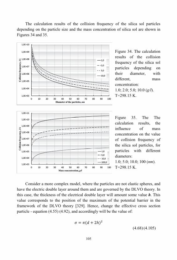
105
The calculation results of the collision frequency of the silica sol particlesdepending on the particle size and the mass concentration of silica sol are shown inFigures 34 and 35.
Figure 34. The calculationresults of the collisionfrequency of the silica solparticles depending ontheir diameter, withdifferent, massconcentration:1.0; 2.0; 5.0; 10.0 (g/l). T=298.15 K.
Figure 35. The Thecalculation results, theinfluence of massconcentration on the valueof collision frequency ofthe silica sol particles, forparticles with differentdiameters:1.0; 5.0; 10.0; 100 (nm). T=298.15 K.
Consider a more complex model, where the particles are not elastic spheres, andhave the electric double layer around them and are governed by the DLVO theory. Inthis case, the thickness of the electrical double layer will amount some value h. Thisvalue corresponds to the position of the maximum of the potential barrier in theframework of the DLVO theory [329]. Hence, change the effective cross sectionparticle - equation (4.55) (4.92), and accordingly will be the value of:
(4.68) (4.105)
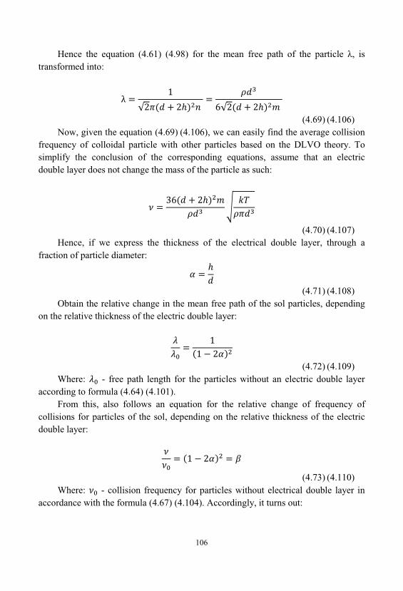
106
Hence the equation (4.61) (4.98) for the mean free path of the particle , istransformed into:
(4.69) (4.106)Now, given the equation (4.69) (4.106), we can easily find the average collision
frequency of colloidal particle with other particles based on the DLVO theory. Tosimplify the conclusion of the corresponding equations, assume that an electricdouble layer does not change the mass of the particle as such:
(4.70) (4.107)Hence, if we express the thickness of the electrical double layer, through a
fraction of particle diameter:
(4.71) (4.108)Obtain the relative change in the mean free path of the sol particles, depending
on the relative thickness of the electric double layer:
(4.72) (4.109)Where: - free path length for the particles without an electric double layer
according to formula (4.64) (4.101). From this, also follows an equation for the relative change of frequency of
collisions for particles of the sol, depending on the relative thickness of the electricdouble layer:
(4.73) (4.110)Where: - collision frequency for particles without electrical double layer in
accordance with the formula (4.67) (4.104). Accordingly, it turns out:
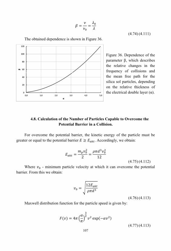
107
(4.74) (4.111)The obtained dependence is shown in Figure 36.
Figure 36. Dependence of theparameter , which describesthe relative changes in thefrequency of collisions andthe mean free path for thesilica sol particles, dependingon the relative thickness ofthe electrical double layer ( ).
4.8. Calculation of the Number of Particles Capable to Overcome thePotential Barrier in a Collision.
For overcome the potential barrier, the kinetic energy of the particle must begreater or equal to the potential barrier . Accordingly, we obtain:
(4.75) (4.112)Where - minimum particle velocity at which it can overcome the potential
barrier. From this we obtain:
(4.76) (4.113)Maxwell distribution function for the particle speed is given by:
(4.77) (4.113)
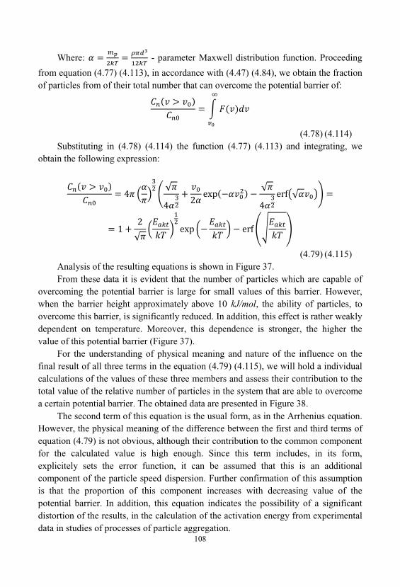
108
Where: - parameter Maxwell distribution function. Proceeding
from equation (4.77) (4.113), in accordance with (4.47) (4.84), we obtain the fractionof particles from of their total number that can overcome the potential barrier of:
(4.78) (4.114)Substituting in (4.78) (4.114) the function (4.77) (4.113) and integrating, we
obtain the following expression:
(4.79) (4.115)Analysis of the resulting equations is shown in Figure 37. From these data it is evident that the number of particles which are capable of
overcoming the potential barrier is large for small values of this barrier. However, when the barrier height approximately above 10 kJ/mol, the ability of particles, toovercome this barrier, is significantly reduced. In addition, this effect is rather weaklydependent on temperature. Moreover, this dependence is stronger, the higher thevalue of this potential barrier (Figure 37).
For the understanding of physical meaning and nature of the influence on thefinal result of all three terms in the equation (4.79) (4.115), we will hold a individualcalculations of the values of these three members and assess their contribution to thetotal value of the relative number of particles in the system that are able to overcomea certain potential barrier. The obtained data are presented in Figure 38.
The second term of this equation is the usual form, as in the Arrhenius equation. However, the physical meaning of the difference between the first and third terms ofequation (4.79) is not obvious, although their contribution to the common componentfor the calculated value is high enough. Since this term includes, in its form, explicitely sets the error function, it can be assumed that this is an additionalcomponent of the particle speed dispersion. Further confirmation of this assumptionis that the proportion of this component increases with decreasing value of thepotential barrier. In addition, this equation indicates the possibility of a significantdistortion of the results, in the calculation of the activation energy from experimentaldata in studies of processes of particle aggregation.
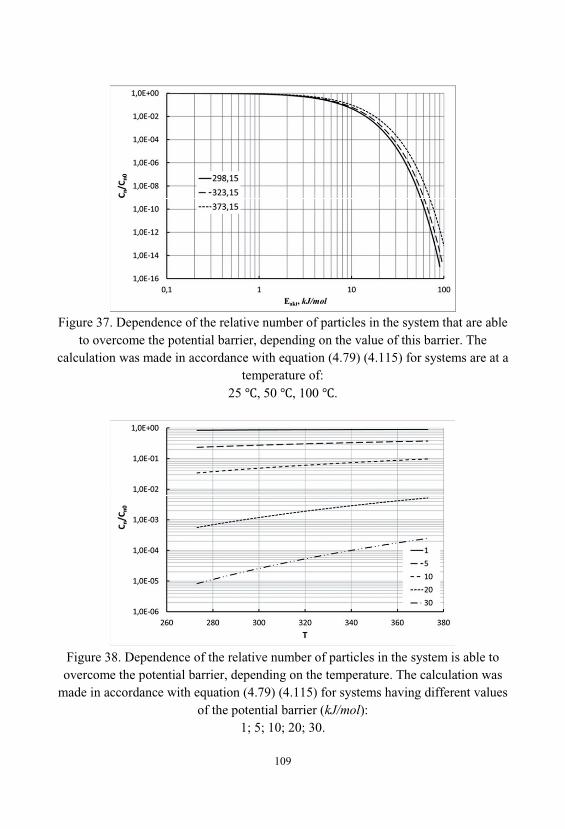
109
Figure 37. Dependence of the relative number of particles in the system that are ableto overcome the potential barrier, depending on the value of this barrier. The
calculation was made in accordance with equation (4.79) (4.115) for systems are at atemperature of:
25 , 50 , 100 .
Figure 38. Dependence of the relative number of particles in the system is able toovercome the potential barrier, depending on the temperature. The calculation was
made in accordance with equation (4.79) (4.115) for systems having different valuesof the potential barrier (kJ/mol):
1; 5; 10; 20; 30.
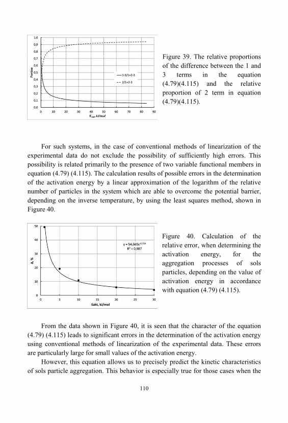
110
Figure 39. The relative proportionsof the difference between the 1 and3 terms in the equation(4.79)(4.115) and the relativeproportion of 2 term in equation(4.79)(4.115).
For such systems, in the case of conventional methods of linearization of theexperimental data do not exclude the possibility of sufficiently high errors. Thispossibility is related primarily to the presence of two variable functional members inequation (4.79) (4.115). The calculation results of possible errors in the determinationof the activation energy by a linear approximation of the logarithm of the relativenumber of particles in the system which are able to overcome the potential barrier, depending on the inverse temperature, by using the least squares method, shown inFigure 40.
Figure 40. Calculation of therelative error, when determining theactivation energy, for theaggregation processes of solsparticles, depending on the value ofactivation energy in accordancewith equation (4.79) (4.115).
From the data shown in Figure 40, it is seen that the character of the equation(4.79) (4.115) leads to significant errors in the determination of the activation energyusing conventional methods of linearization of the experimental data. These errorsare particularly large for small values of the activation energy.
However, this equation allows us to precisely predict the kinetic characteristicsof sols particle aggregation. This behavior is especially true for those cases when the
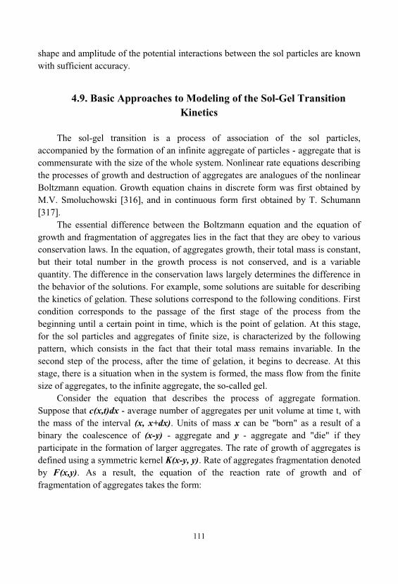
111
shape and amplitude of the potential interactions between the sol particles are knownwith sufficient accuracy.
4.9. Basic Approaches to Modeling of the Sol-Gel TransitionKinetics
The sol-gel transition is a process of association of the sol particles, accompanied by the formation of an infinite aggregate of particles - aggregate that iscommensurate with the size of the whole system. Nonlinear rate equations describingthe processes of growth and destruction of aggregates are analogues of the nonlinearBoltzmann equation. Growth equation chains in discrete form was first obtained byM.V. Smoluchowski [316], and in continuous form first obtained by T. Schumann[317].
The essential difference between the Boltzmann equation and the equation ofgrowth and fragmentation of aggregates lies in the fact that they are obey to variousconservation laws. In the equation, of aggregates growth, their total mass is constant, but their total number in the growth process is not conserved, and is a variablequantity. The difference in the conservation laws largely determines the difference inthe behavior of the solutions. For example, some solutions are suitable for describingthe kinetics of gelation. These solutions correspond to the following conditions. Firstcondition corresponds to the passage of the first stage of the process from thebeginning until a certain point in time, which is the point of gelation. At this stage, for the sol particles and aggregates of finite size, is characterized by the followingpattern, which consists in the fact that their total mass remains invariable. In thesecond step of the process, after the time of gelation, it begins to decrease. At thisstage, there is a situation when in the system is formed, the mass flow from the finitesize of aggregates, to the infinite aggregate, the so-called gel.
Consider the equation that describes the process of aggregate formation. Suppose that c(x,t)dx - average number of aggregates per unit volume at time t, withthe mass of the interval (x, x+dx). Units of mass x can be "born" as a result of abinary the coalescence of (x-y) - aggregate and y - aggregate and "die" if theyparticipate in the formation of larger aggregates. The rate of growth of aggregates isdefined using a symmetric kernel K(x-y, y). Rate of aggregates fragmentation denotedby F(x,y). As a result, the equation of the reaction rate of growth and offragmentation of aggregates takes the form:
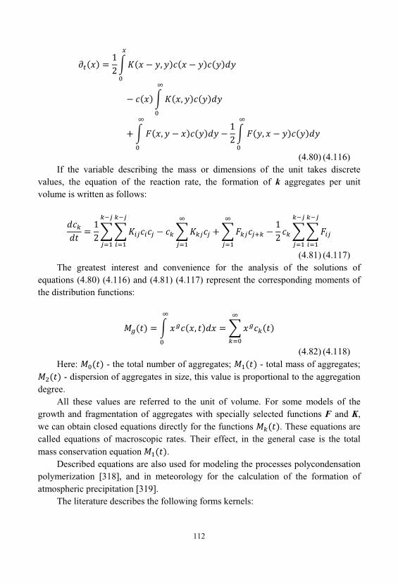
112
(4.80) (4.116)If the variable describing the mass or dimensions of the unit takes discrete
values, the equation of the reaction rate, the formation of k aggregates per unitvolume is written as follows:
(4.81) (4.117)The greatest interest and convenience for the analysis of the solutions of
equations (4.80) (4.116) and (4.81) (4.117) represent the corresponding moments ofthe distribution functions:
(4.82) (4.118)Here: - the total number of aggregates; - total mass of aggregates;
- dispersion of aggregates in size, this value is proportional to the aggregationdegree.
All these values are referred to the unit of volume. For some models of thegrowth and fragmentation of aggregates with specially selected functions F and K, we can obtain closed equations directly for the functions . These equations arecalled equations of macroscopic rates. Their effect, in the general case is the totalmass conservation equation .
Described equations are also used for modeling the processes polycondensationpolymerization [318], and in meteorology for the calculation of the formation ofatmospheric precipitation [319].
The literature describes the following forms kernels:
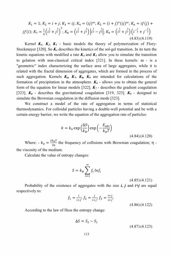
113
; ; ; ; ;
; ; ;
(4.83) (4.119)Kernel K1, K2, K3 - basic models the theory of polymerization of Flory-
Stockmayer [320]. So K3 describes the kinetics of the sol-gel transition. In its turn thekinetic equations with modified a rate K4 and K5 allow you to simulate the transitionto gelation with non-classical critical index [321]. In these kernels: ω - is a"geometric" index characterizing the surface area of large aggregates, while it isrelated with the fractal dimension of aggregates, which are formed in the process ofsuch aggregation. Kernels K6, K7, K8, K9 are intended for calculations of theformation of precipitation in the atmosphere. K6 - allows you to obtain the generalform of the equation for linear models [322]. K7 - describes the gradient coagulation[323]. K8 - describes the gravitational coagulation [319, 323]. K9 - designed tosimulate the Brownian coagulation in the diffusion mode [323].
We construct a model of the rate of aggregation in terms of statisticalthermodynamics. For colloidal particles having a double-well potential and be with acertain energy barrier, we write the equation of the aggregation rate of particles:
(4.84) (4.120)
Where: - the frequency of collisions with Brownian coagulation; η -
the viscosity of the medium. Calculate the value of entropy changes:
(4.85) (4.121)Probability of the existence of aggregates with the size i, j and i+j are equal
respectively to:
; ; ;
(4.86) (4.122)According to the law of Hess the entropy change:
(4.87) (4.123)
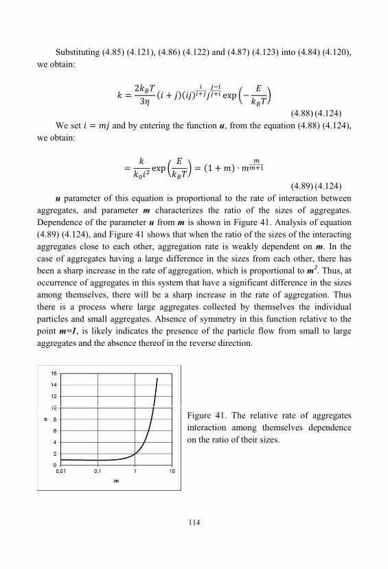
114
Substituting (4.85) (4.121), (4.86) (4.122) and (4.87) (4.123) into (4.84) (4.120), we obtain:
(4.88) (4.124)We set and by entering the function u, from the equation (4.88) (4.124),
we obtain:
(4.89) (4.124)u parameter of this equation is proportional to the rate of interaction between
aggregates, and parameter m characterizes the ratio of the sizes of aggregates. Dependence of the parameter u from m is shown in Figure 41. Analysis of equation(4.89) (4.124), and Figure 41 shows that when the ratio of the sizes of the interactingaggregates close to each other, aggregation rate is weakly dependent on m. In thecase of aggregates having a large difference in the sizes from each other, there hasbeen a sharp increase in the rate of aggregation, which is proportional to m2. Thus, atoccurrence of aggregates in this system that have a significant difference in the sizesamong themselves, there will be a sharp increase in the rate of aggregation. Thusthere is a process where large aggregates collected by themselves the individualparticles and small aggregates. Absence of symmetry in this function relative to thepoint m=1, is likely indicates the presence of the particle flow from small to largeaggregates and the absence thereof in the reverse direction.
Figure 41. The relative rate of aggregatesinteraction among themselves dependenceon the ratio of their sizes.
115
For determining the time of the formation of an infinite aggregate investigate theasymptotic properties of the functions of the size distribution of aggregates for themodel with the kernel K3. For this purpose let us write system of equations for themoment M2, which follows from equations (4.80) (4.116) and (4.82) (4.118), and isreduced to an ordinary differential equation:
(4.90) (4.125)In this model, at time t = tc is formed superparticle - an infinite aggregate. Tc
parameter value is determined from the condition that the moment M2(t), which is thedegree of aggregation of reacting particles, becomes infinite. From (4.90) (4.125) wefind:
(4.91) (4.126)Hence we have:
Further consideration we will carry the model for monodispersed particles ofunit size:
(4.92) (4.127)
(4.93) (4.128)If , we have . To go from the dimensionless time to the true, we
introduce aggregation time - the time interval between the individual elementary actsof aggregation:
(4.94) (4.129)where: N - number of particles per unit volume. Hence the real aggregation time when i=j=1 is equal to:
116
(4.95) (4.130)Analysis of equation (4.95) (4.130) shows that the gelation time is directly
proportional to the viscosity of the medium is inversely proportional to thetemperature and concentration of particles. Increase of the potential barrier in theinteraction of particles leads to an increase in gelation time.
In order to determine the effect of hydrodynamic flows on the aggregationprocess, we consider the case when the unit is growing by consecutive attachment ofindividual particles to it. This process can occur due to the diffusive motion of theparticles, and by the movement of aggregate under the action of hydrodynamic flows. In the latter case the speed of large aggregates is small compared with the thermalvelocity of the particles, with the result that attachment of particles caused only bytheir diffusion.
Given the both processes, the balance equation for the number of particles in theaggregate n has the form:
(4.96) (4.131)where: - frequency of sol particles sticking to the formed aggregate, with
their diffusive motion; - frequency of particle sticking to this aggregate, due totheir introduction into the traffic lane of the aggregate as it moves along a lineartrajectory.
For , assuming that size of the aggregate is large enough , we have:
(4.97) (4.132)here - diffusion coefficient of particles, N - particle concentration.
In a second case:
(4.98) (4.133)where V - speed of the aggregate under the action of hydrodynamic flow. Aggregate, which is formed at the sol-gel transition has fractal geometry, hence
the number of particles in it, respectively, equal to:
117
(4.99) (4.134)Where: - fractal dimension.
Substituting equations (4.97) (4.132)– (4.99) (4.134) into equation (4.96) (4.131)we obtain:
(4.100) (4.135)Where: , . Determine the time in which all the sol particles gather in one aggregate, which
is equal to the size of the whole system:
(4.101) (4.136)Compared to (4.95) (4.130), equation (4.101) (4.136) gives more overestimated
results in gelation time, since it does not account the coalescence of aggregates. However, an analysis of the asymptotic behavior of equation (4.101) (4.136) showsthat it gives results similar to the equation (4.95) (4.130). Thus, from equation (4.101)(4.136) implies that the gelation time is inversely proportional to the particleconcentration:
(4.102) (4.137)Where: – is the particle diameter. So from (4.102) (4.137) that the gelation time is inversely proportional to
countable concentration of particles:
(4.103) (4.138)Accordingly, speed of movement of aggregates has the following proportion
from the gelation time:
118
(4.104) (4.139)To determine the nature of the proportionality of the particle size, it is necessary
to determine the nature of the influence of other factors on this relationship, such asthe diffusion coefficient D. The diffusion coefficient of the particles depends on theaverage speed of movement of particles and their mean free path [330] and usingequations (4.64) (4.101) and (4.66) (4.103) will have the form:
(4.105) (4.140)In view of the above factors for the size the precursor particles we have the
following proportionality if the concentration of the sol is constant and is expressedin counting units:
(4.106) (4.141)If the experiment is kept constant mass concentration, this formula will change
the appearance and will look as follows:
(4.107) (4.142)The shape of the aggregate and its fractal dimension may be different,
depending on the nature of aggregation, and takes values from literature data from the1.75 to 2.5 ÷ 3.0 [324,325].
To assess this relationship experiments were performed to study the effect ofparticle size of the sol, on its gelation time. In all experiments, was maintainedconstant mass concentration of the sol. Obtained dependences are presented in Figure42.
Figure 42 shows that the obtained dependences are well fit into a linearcorrelation. In this case, using the relation (4.106), we can calculate the fractaldimension of the resulting gels. So for a temperature of 80 , it is
=1.4407 0.0023, and for a temperature of 100 - =1.4100 0.0095. Such
small values of fractal dimension, of emerging gels indicate their very open structure.Significant cause of such differences in the value of the fractal dimension ascompared with literature data can only be explained by the fact that in the publishedliterature were investigated gels which have been dried and at them have already
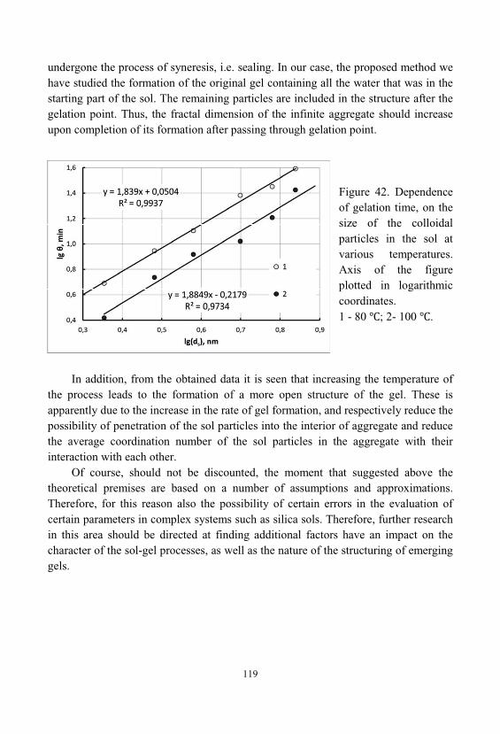
119
undergone the process of syneresis, i.e. sealing. In our case, the proposed method wehave studied the formation of the original gel containing all the water that was in thestarting part of the sol. The remaining particles are included in the structure after thegelation point. Thus, the fractal dimension of the infinite aggregate should increaseupon completion of its formation after passing through gelation point.
Figure 42. Dependenceof gelation time, on thesize of the colloidalparticles in the sol atvarious temperatures. Axis of the figureplotted in logarithmiccoordinates. 1 - 80 ; 2- 100 .
In addition, from the obtained data it is seen that increasing the temperature ofthe process leads to the formation of a more open structure of the gel. These isapparently due to the increase in the rate of gel formation, and respectively reduce thepossibility of penetration of the sol particles into the interior of aggregate and reducethe average coordination number of the sol particles in the aggregate with theirinteraction with each other.
Of course, should not be discounted, the moment that suggested above thetheoretical premises are based on a number of assumptions and approximations. Therefore, for this reason also the possibility of certain errors in the evaluation ofcertain parameters in complex systems such as silica sols. Therefore, further researchin this area should be directed at finding additional factors have an impact on thecharacter of the sol-gel processes, as well as the nature of the structuring of emerginggels.
120
4.10. Formal Kinetic Description of the Sol-Gel Process
It must be recognized that in order to describe the system in the process ofgelation, it is necessary to know the way that it goes in the conversion of the startingsols into the products - gels, nanocomposite materials. Such knowledge would allowconscious control sol-gel transformation. In other words, we must know themechanism of this transformation. It is also important and the time evolution of thetransition of the reaction system from the initial state (initial sols or precursors) to thefinal state - products sol-gel synthesis. This indicates the fact that is necessaryinformation about how quickly occurs, the process of their formation. For answers tothese questions can be used independent field of chemical knowledge, studies thereaction mechanisms and patterns of their occurrence in time - chemical kinetics.
The fundamental concept of chemical kinetics is the concept of reaction rate. The reaction rate is defined as the change in the amount of reactant per unit time, andis related to one of the reaction space.
Strictly speaking, the colloidal system is inherently heterogeneous system. However, because the size of the colloidal particles is very small compared to the sizeof the entire system, therefore, with certain assumptions, for the application to thesesystems may be used to describe the laws of molecular systems. Such a system can beregarded as quasi-homogeneous.
This approach has long been used in physics. So there is the term "quasiparticle"- a concept in quantum mechanics, the introduction of which can significantlysimplify the description of complex quantum systems with internal interaction, suchas solids and quantum liquids.
For example, an extremely complex description of the motion of electrons insemiconductors can be simplified by introducing a quasiparticle called electronconductivity different from the electron mass, and moving in free space. For thedescription of vibrations of the atoms in the lattice sites in the theory of condensedmatter, use phonons to describe the propagation of elementary magnetic excitationsin the system of interacting spins - Magnons.
The idea of using the quasiparticles was first proposed by Landau, to Fermi-liquid theory, to describe the liquid helium-3, and later it was used in the theory ofcondensed matter. To describe status of such systems directly solving theSchrödinger equation for 1023 interacting particles, it is impossible. Circumvent thisdifficulty can be by reducing the problem of interaction of a plurality of particles to asimple problem with a non-interacting quasiparticles [326]. Similarly, we canconsider other systems, in particular - colloidal systems.
As an example of quasi-homogeneous approach to the description ofheterogeneous systems, we can give an example of the description of processes in
121
porous media. In accordance with the quasi-homogeneous model, the dispersemedium is represented as a continuous [327]. Thus, the most traditional method ofdescribing transport processes in porous media is a quasi-homogeneousapproximation, based on replacing the real dispersion medium by a continuousmedium with effective parameters. For this purpose we introduce the effectiveparameters - coefficients of heat transfer, and mass transfer in volume of quasi-homogeneous porous body, the effective reaction rate constants. In this case, theheterogeneous reaction, formally regarded as homogeneous. To account for theinfluence of the geometry of the phase interface often used corresponding simplifiedgeometric models for the structure of the medium. However, the quasi-homogeneousapproximation in some cases is not sufficiently precise [328].
Depending on whether the process is quasi-homogeneous or heterogeneous, thereaction space concept is different. In the quasi-homogeneous system process isperformed in the entire volume of the system, in a heterogeneous system, - at theinterface. An example of such a system is the deposition of the sol particles on a solidsubstrate. Mathematically, this is written as:
quasi-homogeneous process:
heterogeneous process:
The sign in front of the derivative is formally reflects the situation taking placeduring the process, namely, what is happening with this substance, it is expended oraccumulated. n - Number of particles participating in this moment in this process, inthis system. If in the process of quasi-homogeneous system volume remains constant(closed system), we have:
Therefore the rate associated with a change in the countable concentration ( )of the reactant with time:
Assumed that the rate of reaction - positive value. The mathematical basis for aquantitative description of the reaction is the basic postulate of chemical kinetics - the
122
law of mass action. In the kinetic formulation of the law expresses proportional to therate with concentrations of the reactants:
Where: k - rate constant of the reaction. This is an important kinetic parameter, formally reflecting the values of the reaction rate at the concentrations of thereactants are equal to one. The rate constant is independent of concentration and time, but for most of the reactions is temperature dependent. The index i - refers to the i-thtype of reacting particles.
In formal kinetics is believed that if the conversion of the starting reactants intoproducts is not accompanied by any intermediate materials or particles, i.e. proceedsin one step, such a reaction is simple or elementary. This approach can also beapplied to describe the kinetics of the interaction of the colloidal particles.
Consider the direct kinetic problem for the cases of passing in a simple reactionsbetween the particles in a closed isothermal system (volume and temperature areconstant). In this case, a simple reaction scheme, which goes in one step, and whereinonly one reagent is involved, the particles of type A, can be written as:
Where: n - the order of the reaction in this case are the same in magnitude, withparticle numbers that participate in interaction of elementary act. Depending on thevalue of n, can be distinguished cases of mono-, bi-, and three-particle interactionsinvolving one type of the reacting particles. Mathematical model of such reactionscan be represented by a differential equation:
(4.108) (4.143)With initial conditions corresponding to the concentration of the particles A at
the start of the reaction : . Concentration called initial concentration and the value at each time -
the current concentration. Analytical solution of the direct kinetic problem is toestablish a functional relationship of current concentration with time.
123
After a number of obvious transformations we obtain the general solution of thedirect kinetic problem, which allows us to write the current dependence of theconcentration of the reagent depending on time:
(4.109) (4.144)Obviously, depending on the order of the reaction, the concentration of the
precursor particles decreases with time in various ways. For example, if for the orderof the reaction is formally to attribute the values 0, 2, or 3, and then we obtain thefollowing expression. As we see, the equation in the form (4.109), is not applicablefor a first order reaction because for n = 1, it comprises uncertainty of the 0/0 type. This uncertainty can be opened by L’Hospital’s rule. Thus, in a first order reaction, the flowing reagent concentration decreases with time according to the exponentiallaw:
(4.110) (4.145)
(4.111) (4.146)
(4.112) (4.147)
(4.113) (4.148)Obtained according to (4.110) (4.145)-(4.113) (4.148) is called the equation of
the kinetic curves. In practical terms, the kinetic curves can be convenientlyrepresented in the form of graphs. So in the figure 43 shows the form of the kineticcurves showing the consumption of reagent in hypothetical reactions having differentorders, but equal, numerical values of the rate constants, and the initial concentrationof the reacting substance. In fact, these equations analysis was conducted for theirdimensionless form. This indicates that they are universal and can be used to solvedifferent problems.
From the dimensional and similarity theory it is known that the numerical valuesof the variables and coefficients of the equations depend on the choice of scales, dimensions or characteristic values. Bad choice of dimensions, because of the limitednumber of bits to represent numbers in computers, can lead to loss of accuracy when
124
performing arithmetic operations with very large and very small numbers. Therefore, it is important to have a good scaling of the variables, that is, to move fromdimensional to dimensionless variables with a reasonable choice of scale dimensionalvariables. Selection of scale or, in other words, the choice of the characteristic valuesof the physical quantities made so that the dimensionless variables did not differgreatly from unity. This procedure was done above.
In dimensionless variables the equations retain their shape. Therefore, whenwriting algorithms and programs, can use the original form of the dimensionalequations and dimensionless variables, used in the calculations by specifying theinput data, for the coefficients of the equations and boundary conditions, inaccordance with the variant of nondimensionalization variables.
The data show that with the increase of the order, decrease in the concentrationof the reagent with time becomes less intense.
Based on these kinetic curves for the particles in the process of gelation in thereaction of zero order, with n = 0, and the rate constant is corresponds to thefrequency of collisions. Hence, using equation (4.92) (4.127) and (4.93) (4.128) forthe model in the framework of statistical thermodynamics (Section 4.9), for thedimensionless parameters we have degree of conversion of primary particles of 0.5. Accordingly, the dimensionless concentration will also be equal to 0.5. As a result, we obtain the dimensionless gel time for the cases of processes with different order ofthe reaction. The results are shown in Figures 42, 43 and in Table 2.
Table 2. Dimensionless time for the gelation process, with a different order of the
reaction. The number of particles in the elementary act
n=0 n=1 n=2 n=3tc 0.500000 0.693147 1.000000 1.500000
Considering the elementary act of interaction of particles sols each other, we canconclude that the case of the reaction order and , have more likelyasymptotic and the theoretical value. Since their physical meaning in this case is notclear enough. However, a deeper physical meaning bear in themselves model of theprocesses of the second and third orders. This is due to the fact that the second-orderreaction is the interaction of two identical particles with each other, and the thirdorder - the simultaneous collision of three particles. Naturally the probability of thesecond process is significantly lower. Such processes will likely determine theappearance of particles with a coordination number of 3 or more in the gel structure. They will also lead to an increase of the fractal dimension of the emerging gel,
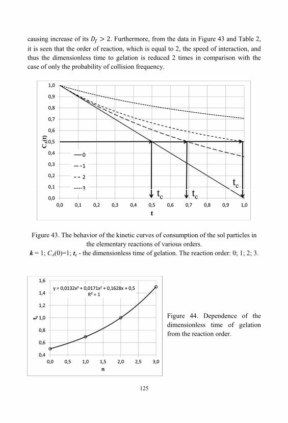
125
causing increase of its . Furthermore, from the data in Figure 43 and Table 2,
it is seen that the order of reaction, which is equal to 2, the speed of interaction, andthus the dimensionless time to gelation is reduced 2 times in comparison with thecase of only the probability of collision frequency.
Figure 43. The behavior of the kinetic curves of consumption of the sol particles inthe elementary reactions of various orders.
k = 1; CA(0)=1; tc - the dimensionless time of gelation. The reaction order: 0; 1; 2; 3.
Figure 44. Dependence of thedimensionless time of gelationfrom the reaction order.

126
As seen in Figure 44 , the dependence of the dimensionless time of gelationfrom the reaction order is nonlinear and is well approximated by a polynomial ofdegree 3. This once again confirms the probabilistic nature of the interaction of thesol particles, with each other, in the process of gelation.
127
5. DIFFERENT TYPES OF NANOPHASES
5.1. Nano-Sized Filler
Long time to obtain the nano particles were a core part of nanotechnology. Tothe same subject, belonged basic postulates of nanotechnology, those were laid downat the beginning of the last century, in the ideas of R. Zsigmondy and T. Svedberg. However, the essence of nanotechnology and nanomaterials formulated R. Feynman, who offered two diametrically opposed approaches to the creation of nanomaterials"bottom - up" and "top - down". The first of these methods is linked to theimplementation of processes in atomic and molecular self-assembly or assemblytechnology of the final products. The second is related to the processes of mechanicaldisintegration, severe plastic deformation, decomposition of solid solutions, etc. [14,151-153]. Actually other technological approaches do not exist.
"Top - down" is based on reducing the size of the physical bodies, bymechanical or other treatment, up to objects with ultra-microscopic, nanometricparameters. This variant obtaining nanomaterials has fundamental physicallimitations. For example when using photolithography techniques is the dimensionallimitations associated with the wavelength of incident radiation. By mechanicalaction on the material requires the application of sufficiently high energy to create anew surface when the particles break down to the submicron level. In addition, anymechanical impact has a bilateral in nature by virtue of Newton's third law. If youdestroy some material, you are destroyed simultaneously, instrument of destroying. Thus, you bring to the product obtained as a result of this impact, the particles of theinstrument itself. On the nanometric scale, these contamination even in an amount ofabout several ppm, prove fatal.
The idea of technology "bottom - up" is that the assembly of produced"construction", is carried out directly from the lower-level elements (atoms, molecules, etc.), which are stacked to the desired order.
An important aspect of this approach is that it has been included in the essenceof the nature of the chemicals. For centuries, chemists were engaged in obtainingnew, more complex chemicals, by assembling them out of individual atoms or groups
128
of atoms, complicated molecules from more simple molecules. Giant crystalsobtained by laying in the correct order of individual atoms or molecules. The mainproblem is only how, to control this process to stop it at the desired level, whichcorresponds to the desired level of nanometer dimensions.
Of course, the first path is not closed today. There are a lot of technologicalmethods, and is constantly create new methods of crushing of materials withoutcontamination of their by foreign impurities. There are methods involving the use ofexplosive technology, and high-energy flows, plasma, radiation, laser, acoustic andother methods.
But nevertheless assembly "bottom - up", the most natural process in whichthere are no fundamental limitations and physical prohibitions on the possibility ofobtaining structures in the range from the atomic to the macroscopic level.
In connection with this, we consider the chemical methods for the preparation ofnanoparticles which may be the fillers in nanocomposites.
There are many chemical methods that can be used to obtain nanoparticles ofvarious materials. Naturally, different classes of chemical substances and compoundsobtained by various methods appropriate to the chemical properties of substancesfrom which are obtained nanoparticles.
For example, to obtain the metal nanoparticles can be applied several types ofreducing agents, e.g. complex hydrides, alkyl hydrides, etc. Thus, molybdenumnanoparticles can be prepared by reduction of a molybdenum salt using sodium tri-ethylhydroborate NaB(C2H5)3H, dissolved in toluene. This reaction gives a goodyield of molybdenum nanoparticles with dimensions of 1 ÷ 5 nm. Reaction equationis as follows:
Nanoparticles of alumina can be obtained by decomposition of adduct, tri-ethylamine and aluminum hydride (C2H5)3N:AlH3, dissolved in toluene, followed byheating to 105 °C for two hours. As a catalyst for this reaction is used titanium iso-propoxide. The choice of catalyst, determines the size of the nanoparticles formed bythis reaction. When using titanium iso-propoxide possible to obtain particles with adiameter of 80 nm. To prevent agglomeration of nanoparticles to solution may also beadded surfactants such as oleic acid [151].
Obtaining metal nanoparticles in the conditions of highly energy impacts on thechemical system are associated with the appearance of strong reducing agents withhigh activity, such as hydrated electrons, radicals and excited particles.
Photochemical (photolysis) and radiation-chemical (radiolysis) recovery differby energy. For photolysis, are typical of energy less than 60 eV, and for radiolysis -
129
more than 100 eV. The main features of chemical processes under the influence ofhigh energy radiation include: non-equilibrium in the distribution of particles byenergy, the overlap of the characteristic times of physical and chemical processes. Decisive role for the chemical transformations of the active particles has amultichannel, and non-stationary processes occurring in reacting systems.
Photo- and radiation-chemical reduction, when compared with the chemicalmethod has certain advantages. These processes are different higher puritynanoparticles produced by such recovery, as there are no impurities are obtainedusing conventional chemical reducing agents. Moreover, using techniques photo- andradiation-chemical reduction is possible synthesis of nanoparticles in solids at lowtemperatures.
Photochemical reduction in solution most often used for the synthesis of noblemetal particles. Upon receipt of such particles from the corresponding salts, as themedium use their solutions in water, alcohol and organic solvents. In these media byexposure to light are formed active species. However, as a result of photoreduction isnot only a process of preparation of nanoparticles of a certain size, but there is aformation of larger aggregates.
As an example of photochemical production of films of metals, nanometerthickness, discloses a method for applying a metallic coating to a substrate. Thesubstrate is placed in a reactor with a pressure of about 10 Pa. Next, the substrate isheated to a temperature of 50-70 °C, is fed into a reaction zone a mixture of hydrogenand precursor vapor, and the substrate was subjected to UV radiation in thewavelength range 126-172 nm. Here the flux of hydrogen was fed at a rate 0.3-4.0 l/h, and vapors of the precursor at a temperature of 25-50 °C was fed at a rate of 2 ÷ 4 l/h, with the help of the carrier gas, argon. As a result, takes place chemical reaction ofreducing the corresponding metal from the precursor to the metallic state. In this case, on the surface of the substrate, a film is formed, consisting of grains of metal, thesizes of 100 ÷ 150 nm. Decomposition of the precursor is achieved through the photodissociation of hydrogen and oxygen with the formation of highly reactive particlessuch as the H, O, O3, which sharply reduce its decomposition temperature. In themetallic coatings can be prepared from Pd, Pt, Ni and Cu. As the substrate, usecopper, polymers, ceramics, silicon. As precursors using volatile organometalliccompounds such as fluorinated -diketonates (hexa-fluoro- -diketonate - HFA)palladium (Pd(HFA)2), platinum (Pt(HFA)2), nickel and copper, as well as volatile, trimetilnyh derivatives Pt (IV)((CH3)3Pt (HFA)Py) [285].
Radiation-chemical reduction for the synthesis of metal nanoparticles, due totheir availability and reproducibility, is becoming more widespread. In the synthesisof metal nanoparticles in a liquid phase, are of great importance issues related to thespatial distribution of the primary and intermediate products. When radiolysis unlike
130
photolysis for the intermediate active particles or radicals observed uniformdistribution by volume, it promotes the synthesis of nanosized particles with a narrowsize distribution.
Currently, for the formation of metal nanoparticles are widely used porousinorganic materials such as zeolites. Solid zeolites having pores and channels arestrictly certain size, are convenient matrices for stabilizing the nanoparticles withdesired properties. Typically use two basic methods for preparation of nanoparticlesin the pores of the zeolite. One of them is related to the direct adsorption of metalvapor in the pores, thoroughly dehydrated zeolites. Another more widely usedmethod is based on chemical transformations of precursors introduced into the poresin the form of metal salts, metal carboxylates, metal complexes and organometalliccompounds. In a similar way, for example in the channels of the molecular sieveswere obtained nano-wire with a diameter of 3 nm and a length of hundreds of timeslarger.
High thermal and chemical stability of zeolites with introduced inside thenanoparticles can be considered as the most promising catalysts.
To chemical methods for the synthesis of oxides and sulfides nanoparticles, relate different versions of the sol-gel synthesis. When implementing the process ofthe sol-gel synthesis are also used various precursors, such as salts, alkoxides, chelatecompounds, etc. The process is catalyzed by a change in pH, of the initial solution. Inacidic media are formed linear chains in alkaline media - having branched chains. Replacing metal alkoxides the corresponding compound of thioalcohols M(SR)n, andreacted with hydrogen sulfide can be obtained nanoparticles of metal sulfides.
A separate group of methods for the synthesis of nanoparticles are reactions inmicelles, emulsions, suspensions, and dendrimers (nanoreactors). Micelles - particlesin colloidal systems consisting of insoluble in this medium of the nucleus, which isvery small in size, surrounded by a stabilizing shell of the adsorbed ions and solventmolecules. They are associates of the characteristic structure, the shell of which isconstructed of a plurality of amphiphilic molecules consisting of long-chain radicalslyophobic and lyophilic polar groups.
For the preparation of nanoparticles of metals and their compounds usedmicelles, emulsions, and dendrimers, which can be regarded as a kind of nanoreactorsit possible to synthesize particles of a certain size.
In section 1.3., of the present monograph, some questions on the production ofsolutions, of SiO2 colloidal particles - silica sols, been described in details. However, for various fillers for nanocomposites, is important to obtain a wide range of particlesizes, from a few nanometers to hundreds of nanometers. Therefore, to obtainconcentrated and stable silica sols are necessary enlargement of particles and ensure amonodisperse of system.
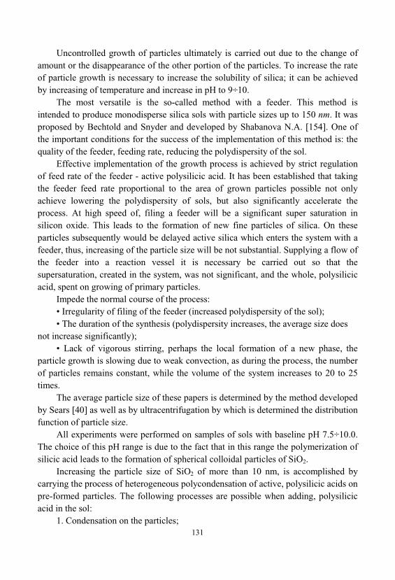
131
Uncontrolled growth of particles ultimately is carried out due to the change ofamount or the disappearance of the other portion of the particles. To increase the rateof particle growth is necessary to increase the solubility of silica; it can be achievedby increasing of temperature and increase in pH to 9÷10.
The most versatile is the so-called method with a feeder. This method isintended to produce monodisperse silica sols with particle sizes up to 150 nm. It wasproposed by Bechtold and Snyder and developed by Shabanova N.A. [154]. One ofthe important conditions for the success of the implementation of this method is: thequality of the feeder, feeding rate, reducing the polydispersity of the sol.
Effective implementation of the growth process is achieved by strict regulationof feed rate of the feeder - active polysilicic acid. It has been established that takingthe feeder feed rate proportional to the area of grown particles possible not onlyachieve lowering the polydispersity of sols, but also significantly accelerate theprocess. At high speed of, filing a feeder will be a significant super saturation insilicon oxide. This leads to the formation of new fine particles of silica. On theseparticles subsequently would be delayed active silica which enters the system with afeeder, thus, increasing of the particle size will be not substantial. Supplying a flow ofthe feeder into a reaction vessel it is necessary be carried out so that thesupersaturation, created in the system, was not significant, and the whole, polysilicicacid, spent on growing of primary particles.
Impede the normal course of the process:• Irregularity of filing of the feeder (increased polydispersity of the sol);• The duration of the synthesis (polydispersity increases, the average size does
not increase significantly);• Lack of vigorous stirring, perhaps the local formation of a new phase, the
particle growth is slowing due to weak convection, as during the process, the numberof particles remains constant, while the volume of the system increases to 20 to 25times.
The average particle size of these papers is determined by the method developedby Sears [40] as well as by ultracentrifugation by which is determined the distributionfunction of particle size.
All experiments were performed on samples of sols with baseline pH 7.5÷10.0. The choice of this pH range is due to the fact that in this range the polymerization ofsilicic acid leads to the formation of spherical colloidal particles of SiO2.
Increasing the particle size of SiO2 of more than 10 nm, is accomplished bycarrying the process of heterogeneous polycondensation of active, polysilicic acids onpre-formed particles. The following processes are possible when adding, polysilicicacid in the sol:
1. Condensation on the particles;
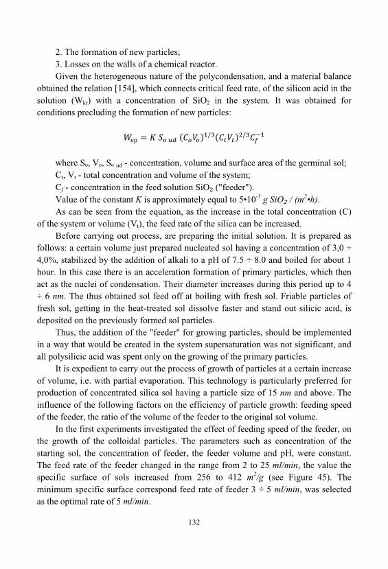
132
2. The formation of new particles;3. Losses on the walls of a chemical reactor. Given the heterogeneous nature of the polycondensation, and a material balance
obtained the relation [154], which connects critical feed rate, of the silicon acid in thesolution (Wkr) with a concentration of SiO2 in the system. It was obtained forconditions precluding the formation of new particles:
where S , V , S ud - concentration, volume and surface area of the germinal sol;Ct, Vt - total concentration and volume of the system;Cf - concentration in the feed solution SiO ("feeder"). Value of the constant K is approximately equal to 5•10-3 g SiO / (m2•h). As can be seen from the equation, as the increase in the total concentration (C)
of the system or volume (Vt), the feed rate of the silica can be increased. Before carrying out process, are preparing the initial solution. It is prepared as
follows: a certain volume just prepared nucleated sol having a concentration of 3,0 ÷4,0%, stabilized by the addition of alkali to a pH of 7.5 ÷ 8.0 and boiled for about 1hour. In this case there is an acceleration formation of primary particles, which thenact as the nuclei of condensation. Their diameter increases during this period up to 4÷ 6 nm. The thus obtained sol feed off at boiling with fresh sol. Friable particles offresh sol, getting in the heat-treated sol dissolve faster and stand out silicic acid, isdeposited on the previously formed sol particles.
Thus, the addition of the "feeder" for growing particles, should be implementedin a way that would be created in the system supersaturation was not significant, andall polysilicic acid was spent only on the growing of the primary particles.
It is expedient to carry out the process of growth of particles at a certain increaseof volume, i.e. with partial evaporation. This technology is particularly preferred forproduction of concentrated silica sol having a particle size of 15 nm and above. Theinfluence of the following factors on the efficiency of particle growth: feeding speedof the feeder, the ratio of the volume of the feeder to the original sol volume.
In the first experiments investigated the effect of feeding speed of the feeder, onthe growth of the colloidal particles. The parameters such as concentration of thestarting sol, the concentration of feeder, the feeder volume and pH, were constant. The feed rate of the feeder changed in the range from 2 to 25 ml/min, the value thespecific surface of sols increased from 256 to 412 m2/g (see Figure 45). Theminimum specific surface correspond feed rate of feeder 3 ÷ 5 ml/min, was selectedas the optimal rate of 5 ml/min.
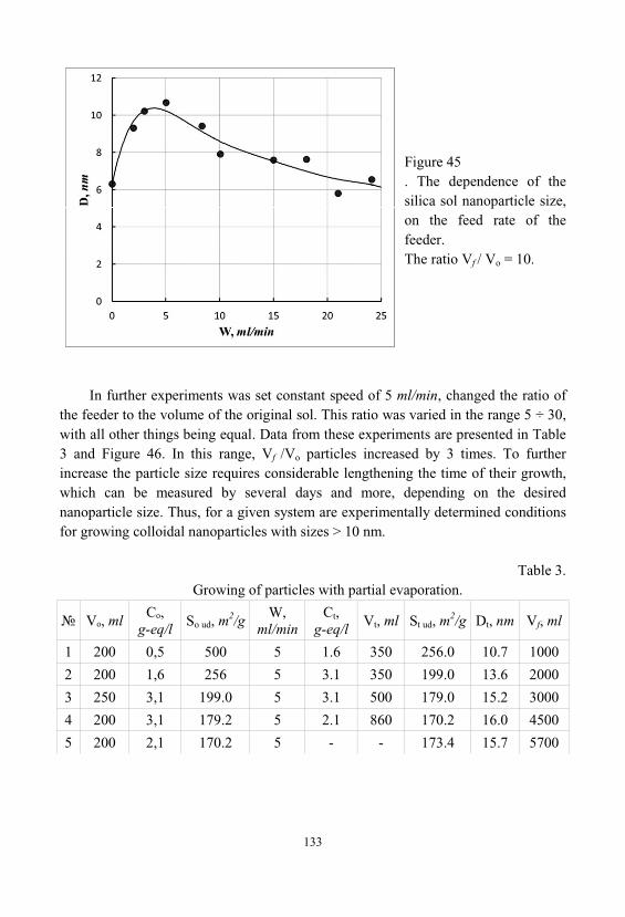
133
Figure 45. The dependence of thesilica sol nanoparticle size, on the feed rate of thefeeder. The ratio Vf / Vo = 10.
In further experiments was set constant speed of 5 ml/min, changed the ratio ofthe feeder to the volume of the original sol. This ratio was varied in the range 5 ÷ 30, with all other things being equal. Data from these experiments are presented in Table3 and Figure 46. In this range, Vf /Vo particles increased by 3 times. To furtherincrease the particle size requires considerable lengthening the time of their growth, which can be measured by several days and more, depending on the desirednanoparticle size. Thus, for a given system are experimentally determined conditionsfor growing colloidal nanoparticles with sizes > 10 nm.
Table 3. Growing of particles with partial evaporation.
V , ml,
g-eq/lS ud, m
2/gW,
ml/minCt,
g-eq/lVt, ml St ud, m
2/g Dt, nm Vf, ml
1 200 0,5 500 5 1.6 350 256.0 10.7 1000
2 200 1,6 256 5 3.1 350 199.0 13.6 2000
3 250 3,1 199.0 5 3.1 500 179.0 15.2 3000
4 200 3,1 179.2 5 2.1 860 170.2 16.0 4500
5 200 2,1 170.2 5 - - 173.4 15.7 5700
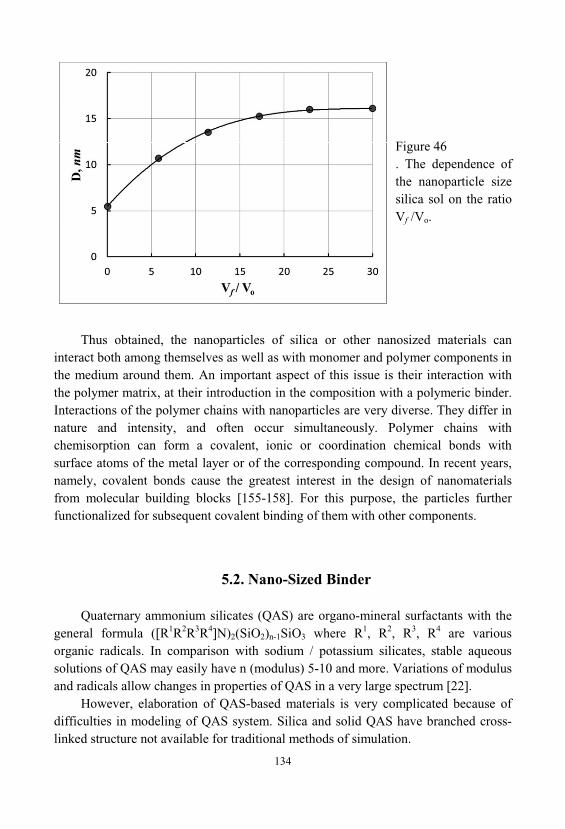
134
Figure 46. The dependence ofthe nanoparticle sizesilica sol on the ratioVf /Vo.
Thus obtained, the nanoparticles of silica or other nanosized materials caninteract both among themselves as well as with monomer and polymer components inthe medium around them. An important aspect of this issue is their interaction withthe polymer matrix, at their introduction in the composition with a polymeric binder. Interactions of the polymer chains with nanoparticles are very diverse. They differ innature and intensity, and often occur simultaneously. Polymer chains withchemisorption can form a covalent, ionic or coordination chemical bonds withsurface atoms of the metal layer or of the corresponding compound. In recent years, namely, covalent bonds cause the greatest interest in the design of nanomaterialsfrom molecular building blocks [155-158]. For this purpose, the particles furtherfunctionalized for subsequent covalent binding of them with other components.
5.2. Nano-Sized Binder
Quaternary ammonium silicates (QAS) are organo-mineral surfactants with thegeneral formula ([R1R2R3R4]N)2(SiO2)n-1SiO3 where R1, R2, R3, R4 are variousorganic radicals. In comparison with sodium / potassium silicates, stable aqueoussolutions of QAS may easily have n (modulus) 5-10 and more. Variations of modulusand radicals allow changes in properties of QAS in a very large spectrum [22].
However, elaboration of QAS-based materials is very complicated because ofdifficulties in modeling of QAS system. Silica and solid QAS have branched cross-linked structure not available for traditional methods of simulation.
135
Existing methods of study of such processes comprise two principal approaches:modeling by Monte-Carlo random simulation, and the thermodynamic description.
The Monte-Carlo approach considers the solid-phase process of microporouscluster formation as a random process, in which the initially empty space is dividedinto cells every of which can be eventually filled with a solid particle (silica). Theprobability of such event is assumed independent of the pre-history of the process. The main drawback of this approach consists in the ignorance of the determination ofthis process. Therefore, such approximation is applicable only to solid structures withvery low density, in which the probability of neighborhood of two or more emptycells is negligible [164-166]. The applicability of Monte-Carlo approach is limited bythree principal factors: finite size of the studied system (for various capacities ofcomputers, from some thousand to some million cells), negligibility of surfacetension, and absolute randomness of micropore formation processes. Therefore, thevalidity of Monte-Carlo approach for major part of real systems is very doubtable.
The alternative approach deals with the thermodynamic determination of theconsidered process, without taking into account the eventuality of silica precipitation[167,168]. Thermodynamic approach uses macroscopic description based mostly onsuch or such distribution of structural elements in energy. This approach is wellapplicable to a system consisting of a very large number of cells and allowsobtainment of very important information about microporous system and dependenceof its properties on preparation conditions. However, since energy distribution is notdirectly related to internal surface area, this one cannot be found from equations ofthermodynamic model [23,170].
The problem of silica aggregation from quaternary ammonium solution inlimited volume has been considered. The system has been described by a modelcombining Monte-Carlo approach with thermodynamic limitations. Thermodynamiccharacteristics have been estimated by statistical polymer method (equilibriumversion). The model has been employed for estimation of such properties as monomerconcentration and tortuosity. The results of computer simulation have been used forforecasting of properties of coatings and practical preparation of samples coated withquaternary ammonium silicate-based composition [171].
In recent years begun to develop application silicate polymer compositematerials, which are water soluble silicates with additives of active substances furanseries. They operate under acidic and neutral media and under the influence ofelevated temperatures. The materials are cheap and easy to manufacture non-toxic, non-flammable. Cost of polymer silicate materials commensurate with the cost ofcement concrete and several times lower than the cost of polymer concrete. SilicatePolymer materials as concrete, mortar, putties used for making constructions of
136
various purpose, monolithic and tile lining. There is a certain perspective, incomposite materials based on liquid glass binder modified with furfuryl alcohol.
A significant increase in strength, thermal and fire resistance, of silicate matrixis achieved by introducing into the composition of esters of orthosilicic acid andfurfuryl alcohol (tetra-furfuryloxysilanes - TFS). Effect is achieved by strengtheningof contacts between the globules of silica gel and modification of the alkalinecomponent, due to the "inoculation" of the furan radical. Introduction to the binder, additives TFS leads to the formation of nanoparticles of SiO2, and furfuryl alcohol, which fills the matrix, and forms the crosslinked polymer. These particles act ascenters of nucleation and crystallization. Adding TFS increases the mechanical andchemical resistance of the binder, and this approach began to be widely used for thepreparation of acid-resistant concrete and coatings [23,172].
Can be explained this effect by the following considerations. On the thermalstability of oxo-compounds can be judged by the relative strength of the interatomicbonds M O and C O, in their crystal-structure. The length of the M O and C O, within the coordination polyhedron, can vary significantly, indicating that theirenergy non-equivalence. During the dehydration and with thermal influence maychange denticity, of a certain part of the ligands. In the forming structure, they canbegin simultaneously to perform the function as a ligand, and a solvate that is absentin the system. Increasing denticity of ligands leads to distortion of the oxygenenvironment of the matrix element, or filler, with a corresponding change in thedistance M O and C O in the structure, and hence to changes in their strength.
For increasing the strength, the acid resistance, heat resistance and flameresistance of construction materials and structures of them tetra-furfuryloxysilane(TFS) are input to the binder composition. They are synthesized by trans-esterification of tetra-ethoxysilane, and furfuryl alcohol.
Composition of the resulting binder comprises: a liquid glass - 80 ÷ 95 wt.%tetra-furfuryloxysilane (TFS) - 2÷7 wt.%, hardener, sodium hexafluorosilicate - 13wt.%. Thus as part of the liquid glass used organic alkali liquid glass, wherein theorganic cation is taken 1,4-diazabicyclo[2.2.2]octane-1,4-diium or 1,5-diazabicyclo[3.3.3]undecane-1,5-diium silicates - 2÷4 wt.%. (Figure 47).
Water-soluble silicate containing an organic alkali cation was prepared byreaction the salt of an organic quaternary ammonium derivative with amorphoussilica. A soluble organic alkali silicate, such as tetra-butylammonium silicate (TBAS)was used as a binder component for self-extinguishing [181,182].
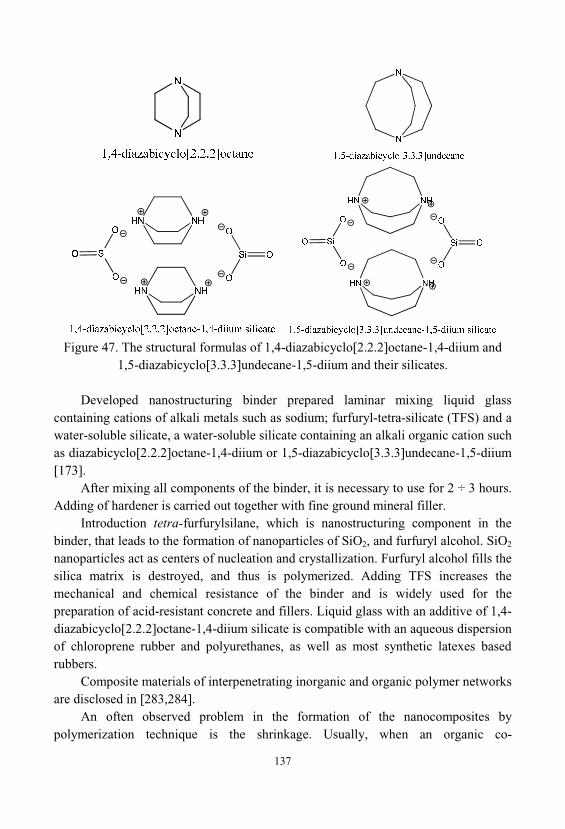
137
Figure 47. The structural formulas of 1,4-diazabicyclo[2.2.2]octane-1,4-diium and
1,5-diazabicyclo[3.3.3]undecane-1,5-diium and their silicates.
Developed nanostructuring binder prepared laminar mixing liquid glasscontaining cations of alkali metals such as sodium; furfuryl-tetra-silicate (TFS) and awater-soluble silicate, a water-soluble silicate containing an alkali organic cation suchas diazabicyclo[2.2.2]octane-1,4-diium or 1,5-diazabicyclo[3.3.3]undecane-1,5-diium[173].
After mixing all components of the binder, it is necessary to use for 2 ÷ 3 hours. Adding of hardener is carried out together with fine ground mineral filler.
Introduction tetra-furfurylsilane, which is nanostructuring component in thebinder, that leads to the formation of nanoparticles of SiO2, and furfuryl alcohol. SiO2
nanoparticles act as centers of nucleation and crystallization. Furfuryl alcohol fills thesilica matrix is destroyed, and thus is polymerized. Adding TFS increases themechanical and chemical resistance of the binder and is widely used for thepreparation of acid-resistant concrete and fillers. Liquid glass with an additive of 1,4-diazabicyclo[2.2.2]octane-1,4-diium silicate is compatible with an aqueous dispersionof chloroprene rubber and polyurethanes, as well as most synthetic latexes basedrubbers.
Composite materials of interpenetrating inorganic and organic polymer networksare disclosed in [283,284].
An often observed problem in the formation of the nanocomposites bypolymerization technique is the shrinkage. Usually, when an organic co-
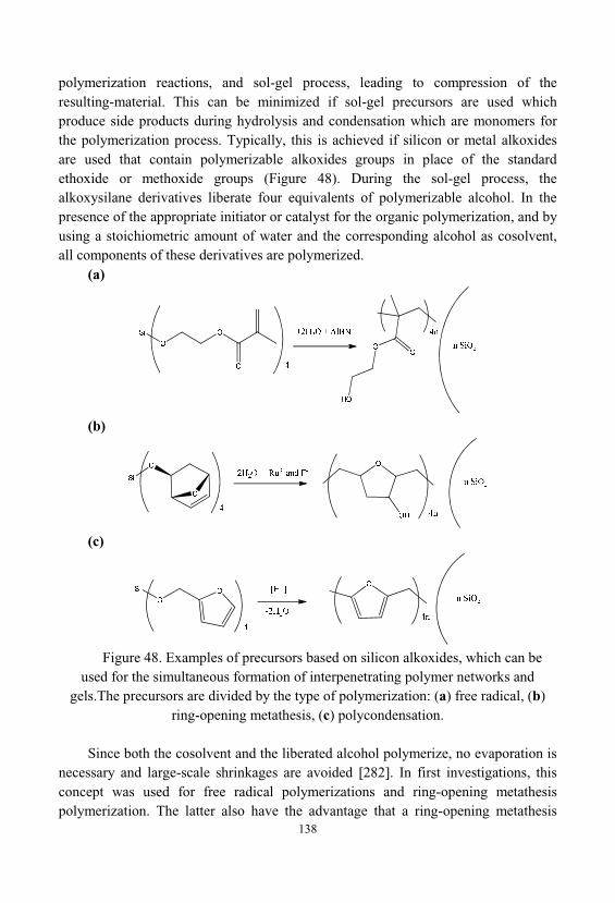
138
polymerization reactions, and sol-gel process, leading to compression of theresulting-material. This can be minimized if sol-gel precursors are used whichproduce side products during hydrolysis and condensation which are monomers forthe polymerization process. Typically, this is achieved if silicon or metal alkoxidesare used that contain polymerizable alkoxides groups in place of the standardethoxide or methoxide groups (Figure 48). During the sol-gel process, thealkoxysilane derivatives liberate four equivalents of polymerizable alcohol. In thepresence of the appropriate initiator or catalyst for the organic polymerization, and byusing a stoichiometric amount of water and the corresponding alcohol as cosolvent, all components of these derivatives are polymerized.
(a)
(b)
(c)
Figure 48. Examples of precursors based on silicon alkoxides, which can beused for the simultaneous formation of interpenetrating polymer networks and
gels.The precursors are divided by the type of polymerization: (a) free radical, (b)ring-opening metathesis, (c) polycondensation.
Since both the cosolvent and the liberated alcohol polymerize, no evaporation isnecessary and large-scale shrinkages are avoided [282]. In first investigations, thisconcept was used for free radical polymerizations and ring-opening metathesispolymerization. The latter also have the advantage that a ring-opening metathesis
139
polymerization shows much less shrinkage compared to a usual additionpolymerization (Figure 48 b). Water-based Ring opening metathesis polymerizationis also compatible with the typical sol-gel conditions. Recently, the concept ofcombination of sol-gel process and polymerization was extended to polycondensationreactions, the so-called twin polymerizations (Figure 48 c) [281]. For all thesepolymerization reactions, the matching of the polymerization rates between theorganic polymerization and the sol-gel process is necessary. Significant deviationsbetween the reaction rates result in inhomogeneous systems. Polymer precipitationoccurs when the organic polymerization rates are greater than the sol-gelcondensation rate, and inorganic gels swollen with unreacted monomer when thecondensation rate is much faster. If both polymerization rates match each other well, transparent inorganic–polymer composites are obtained.
5.3. Synthesis of Nano-Phase in the Matrix of the CompositeStructure
It is of interest, the introduction of the carbon material in a sol-gel process forobtaining, of nanocomposites, as additives for modifying the functional properties ofthe nanocomposite, as well as the kind of pore-forming component
. Pore-forming components are substances that disappear at various stages offorming and processing of materials to form pores. Carbon materials in the process ofannealing in an oxygen atmosphere, converted into gaseous products. Ability tocontrol the nano sizes of the objects consisting of carbon materials during theirintroduction to the structure of the nanocomposite, determines the feasibility of theiruse to obtain the structures with specified pore sizes [151].
For these technological methods, uses the term "template synthesis" and inputparticles is called a template. New materials with a narrow pore size distribution arenecessary to create semiconductor gas sensor devices a new generation compositemembranes, sorbents for chromatography and others.
Highlight the role of porous materials obtained by the sol-gel method, in thedevelopment of technological operations applying dielectric coatings with low valuesof relative dielectric permittivity, in micro and nanoelectronics [174].
At the present stage of development of silicon nanoelectronics carried outintensive works to decrease the values of resistance of materials by replacingaluminum in conventional conductive materials on the copper conductors (or copperin a shell from TiO2). To reduce the capacitance values are intensively developingresearch on materials with low values of the effective relative dielectric permittivity
140
[175]. One of the main technological methods to reduce the average value of thedielectric permittivity is the formation of an insulating layer with nanopores of sol-gel method.
Another promising area of technology is the formation of the catalytically activenanoparticles on the pore structure. The use of such substrates gives the material inthe form of "nano grass" from the silicon, or heterostructure nano-wires [176,177]. On the basis of obtained in this manner nano-wire manufactured devices, for nano-electronics and nano-opto-electronics [178], for sensor techniques [179] and forphotonics [180]. To date, developed the technology of heterostructure nanowires(nanofilaments) with a change in the composition of both along the growth axis (axialnanowire heterostructures), and in the radial direction (radial nanowireheterostructures). In the review [178] summarizes the data on such structures onsemiconductor compounds A3B5, A2B6 and solid solutions based on them. As thecatalyst, usually used nanoparticles Au, and nanofilaments growth occurs by amechanism "vapor-liquid-crystal".
Interest to metal-polymer nanocomposites obtained by the method ofsynthesizing nano-phase in the structure of the composite matrix, is caused by acombination of unique properties of nanoparticles of metals, their oxides andchalcogenides. Furthermore, these materials also possess unique mechanical, filmforming, and other properties and possibilities of their use as magnetic materials forrecording and storage of information, as sorbents, catalysts and sensors. Monomericand polymeric metal carboxylates are classic examples of such starting materials[183]. Carboxylate compounds such as monomeric or polymeric structure may beused as molecular precursors of nanocomposite materials. In addition, the carboxylategroups belonging to macroligands are effective stabilizers of nanoscale particles. Sometimes, these properties are manifested in the form of a polyfunctionality of onesystem. The amphiphilic nature of carboxylated polymers and copolymers, allowsencapsulating the metal nanoparticles and combining them with the polymer andinorganic matrices, as well as with biological objects. It also allows you to attach tothe nanoparticles properties such as solubility in different environments, the ability toself-organization, etc. [184].
Processes of steric stabilization, flocculation, phase separation, electrostatic andvan der Waals interactions determine, the aggregative stability of the particles in thepolymer matrix. In the work, [185] it was shown that the van der Waals attractiveforce act between the two surfaces of the nanoparticles that are not coated with apolymer, up to 200 nm, causing their aggregation. At the same time, the presence ofan adsorbed layer of polyacrylate or polymethacrylate of ammonium on the surfaceof nanoparticles leads to the appearance repulsive forces between the two surfaces ata distance of 35 nm. Moreover, ammonium polymethacrylate provides more strong
141
repulsion than ammonium polyacrylate. This effect is apparently connected with anadditional steric barrier due CH3-group. Conformational effects of polymer chain areparticularly sensitive to reaction conditions such as pH of the medium.
Accordingly, the thermal conversion processes of unsaturated carboxylate metalcomplexes allow combining the synthesis of nanoparticles with their simultaneousstabilization in a polymer matrix formed by the decarboxylation. Possible to assumethat almost complete homogeneity of thermal conversion processes of monomericcarboxylates is the cause of a fairly narrow character size distribution of metalnanoparticles, and also their morphological features associated with the sphericalshape. In this case there is only a partial heterogeneity in the macroscopic defectsarea [186].
Other monomeric carboxylates, most frequently used as starting products in thepreparation of nanostructured metals are metal octanoates and oleates. Thermolysis oftheir complexes, in combination with surfactants, and other reagents, usually carriedout in a solution of high-boiling solvents (octadecane, octadecene, docosane, octylesters, etc.). The undoubted advantage of the process of thermal decomposition of thecarboxylate compounds in an inert solvent is the possibility of controlled synthesis ofmonodisperse nanocrystals, with a high yield, a narrow size distribution and highdegree of crystallinity [187-190].
A promising direction is to conduct these processes, in the pores of silica gelmatrix, which will allow obtaining materials with unique optical and sensoryproperties. There is the possibility of combining these processes, with processes ofthe sol-gel synthesis.
Thus, methacrylate substituted metalloclusters Hf4O2(OOCC(CH3)=CH2)12 andmethacrylo-yl-propyl-tri-methoxysilane CH2=C(CH3)(COO)-(CH2)3Si(OCH3)3, usedfor hybrid thin films based on silica gel with embedded oxo-clusters hafnium [190-192].
Chemical bonding of the components was carried out with the use ofphotochemical polymerization of methacrylate groups. Alkoxysilane undergoeshydrolysis and condensation with the formation of oxide grid SiO2. Heat treatment at
800 , of the hybrid nanocomposite is accompanied by pyrolysis of the organicpart, and sealing of the oxide network. This leads to the formation of nanostructuredoxide material. Thus it is possible to obtain a monolithic gels and thin films. Carboxylate ligands in organo-mineral composites offer a high degree of cross-linking, through coordination bonds between the polymer and the mineralcomponent.
In [286] has proposed a new synthesis method of organo-mineralnanocomposites on the silicon oxide matrix, using borane compounds ashomogeneous catalysts that promote Si-H bond activation. Describes an innovative
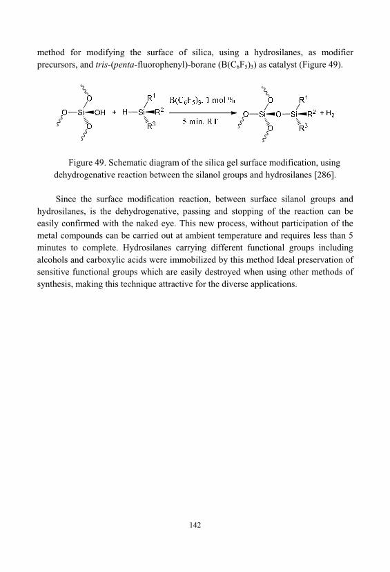
142
method for modifying the surface of silica, using a hydrosilanes, as modifierprecursors, and tris-(penta-fluorophenyl)-borane (B(C6F5)3) as catalyst (Figure 49).
Figure 49. Schematic diagram of the silica gel surface modification, usingdehydrogenative reaction between the silanol groups and hydrosilanes [286].
Since the surface modification reaction, between surface silanol groups andhydrosilanes, is the dehydrogenative, passing and stopping of the reaction can beeasily confirmed with the naked eye. This new process, without participation of themetal compounds can be carried out at ambient temperature and requires less than 5minutes to complete. Hydrosilanes carrying different functional groups includingalcohols and carboxylic acids were immobilized by this method Ideal preservation ofsensitive functional groups which are easily destroyed when using other methods ofsynthesis, making this technique attractive for the diverse applications.
143
6. INFLUENCE OF VARIOUS FACTORS ONSTRUCTURE AND PROPERTIES OF HYBRID
MATERIALS
6.1. Packing of Spherical Nanoparticles of the Filler
The system of pores in a solid is entirely determined by the nature of thepacking of the primary particles. For example, when the hexagonal closest packing ofspherical particles between disposed in a plane, the three nearest tetrahedral cavitiesis octahedral cavity. In subsequent accretions over the octahedral cavity occurs againoctahedral cavity. Superimposed on top of each other octahedral cavities are formedchannels that permeate the whole body of matter in the orthogonal directions [193].
In cubic structures of, the closest packing can also to point out the formation ofinterconnected channels. A package of this type, the void volume is 25.95%. Fromhere is possible to calculate the bulk density of the material ( ):
(6.1)where: k - crystallographic density of the material used as a basis. L - void fraction in the structure of the package. If the lightest of refractory materials have crystallographic density close to 3
g/cm3, the bulk density of the product with the densest packing of 2.2 g/cm3. Fromhere, to obtain materials with a bulk density less than 0.5 g/cm3, it is necessary toachieve a greater porosity of 83%.
Let's try to analyze what the particle packing, can achieve the desired porosity. Typically with decrease in the coordination of number of particles packed in the
packaging structures of particles increases the pore volume. In the case of the densestpackings, the coordination number of the package is 12. Consider the followingoptions for the coordination numbers of the package. Classically, such a packingdensity was 74%, respectively; the porosity of such a package is 26%. Formonodisperse materials denser packaging does not happen.
144
The coordination number is 8. Cubic volume-centered packing. In contrast to thedense packing it has a loose structure. Here, the balls in a flat layer, not touching eachother, and are at a distance 0,155R. Motive construction of this structure ischaracterized in that the balls of the second layer are omitted in the voids of theunderlying layer. Third layer repeats the first and the fourth - the second, etc. Thistype of packaging is a optimal variant spatial arrangement of spheres with acoordination number of 8, and has a lower percentage of its filling volume. The porevolume is 31.98%.
The coordination number is 6. Simple cubic packing. Globular structure, with acoordination number of 6, are built by successive overlay balls packed in a squaregrid so that the centers of the balls of the second layer are located directly above thecenters of the balls first, third - above the centers of the second, etc. Pores in thispackage, enclosed between eight balls in contact, and has six throats, close in shapeto a quadrangular. In this case formed is looser structure in which the pore volume is47.64%
The coordination number is 4. Packing type of diamond and ice. The customizedpackaging is the most loose of all considered regular packages. It is constructed fromlayers of balls of spaced from each other in a plane. Balls next layer are between theballs of the first layer. Centers of the balls of the third layer are located directly abovethe centers of the spheres of the second layer. The fourth layer is located exactlyabove the first, etc. As a result of such packing of balls, the volume of voids producedis 65.99%. In the limit, with a decrease in the coordination number, eachsymmetrically constructed structure with a predetermined pore system should go intoa chaotic folded body with a set of pores which will differ in both shape and size. Boundary of such a transition can be considered packing with a coordination numberof 3.
The coordination number is 3. This package is a very fishnet, loose formationswith a continuous three-dimensional framework. The porosity of this structure is81.5%. Thus, relying solely on the various kinds of packing of spherical particles, isnot possible achieve the desired porosity, and, moreover, to achieve the density lessthan 0.2 g/cm3.
However, if we admit the formation of mixed packing with a coordinationnumber of 2 and 3, i.e., when some particles in the considered package present in theform of short chains consisting of at least three particles. For such packages can beachieved porosity - 95%. The dependence of the porosity from the coordinationnumber, for different methods of stacking spheres is shown in Figure 50, whichshows that the porosity is inversely proportional to the magnitude of the coordinationnumber.
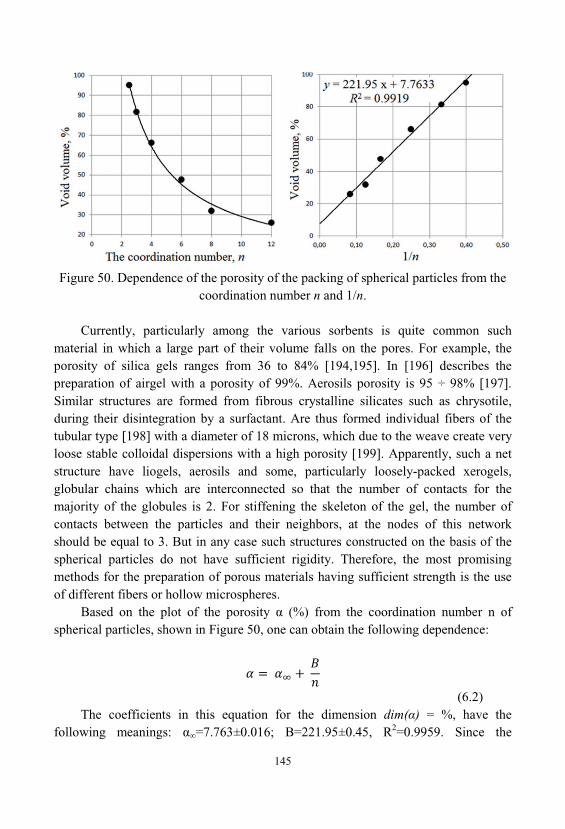
145
Figure 50. Dependence of the porosity of the packing of spherical particles from thecoordination number n and 1/n.
Currently, particularly among the various sorbents is quite common suchmaterial in which a large part of their volume falls on the pores. For example, theporosity of silica gels ranges from 36 to 84% [194,195]. In [196] describes thepreparation of airgel with a porosity of 99%. Aerosils porosity is 95 ÷ 98% [197]. Similar structures are formed from fibrous crystalline silicates such as chrysotile, during their disintegration by a surfactant. Are thus formed individual fibers of thetubular type [198] with a diameter of 18 microns, which due to the weave create veryloose stable colloidal dispersions with a high porosity [199]. Apparently, such a netstructure have liogels, aerosils and some, particularly loosely-packed xerogels, globular chains which are interconnected so that the number of contacts for themajority of the globules is 2. For stiffening the skeleton of the gel, the number ofcontacts between the particles and their neighbors, at the nodes of this networkshould be equal to 3. But in any case such structures constructed on the basis of thespherical particles do not have sufficient rigidity. Therefore, the most promisingmethods for the preparation of porous materials having sufficient strength is the useof different fibers or hollow microspheres.
Based on the plot of the porosity (%) from the coordination number n ofspherical particles, shown in Figure 50, one can obtain the following dependence:
(6.2)The coefficients in this equation for the dimension dim( ) = %, have the
following meanings: =7.763±0.016; B=221.95±0.45, R2=0.9959. Since the
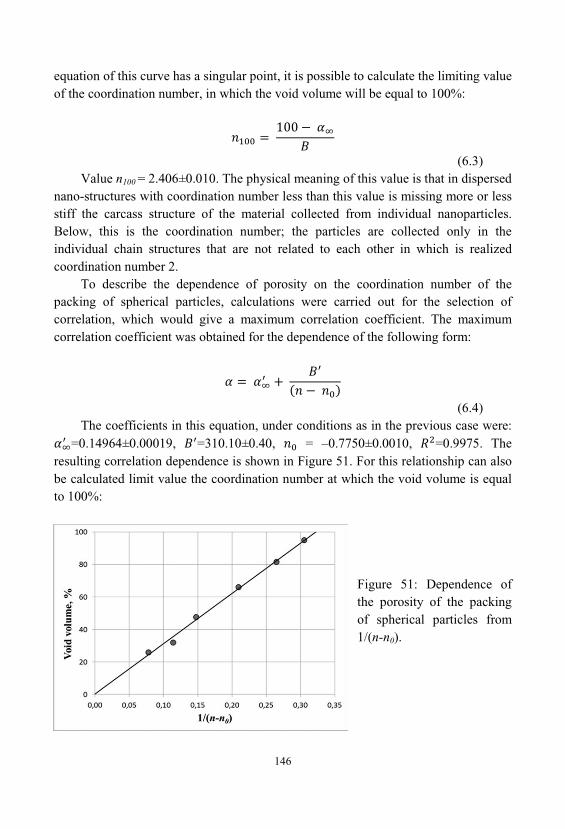
146
equation of this curve has a singular point, it is possible to calculate the limiting valueof the coordination number, in which the void volume will be equal to 100%:
(6.3)Value n100 = 2.406±0.010. The physical meaning of this value is that in dispersed
nano-structures with coordination number less than this value is missing more or lessstiff the carcass structure of the material collected from individual nanoparticles. Below, this is the coordination number; the particles are collected only in theindividual chain structures that are not related to each other in which is realizedcoordination number 2.
To describe the dependence of porosity on the coordination number of thepacking of spherical particles, calculations were carried out for the selection ofcorrelation, which would give a maximum correlation coefficient. The maximumcorrelation coefficient was obtained for the dependence of the following form:
(6.4)The coefficients in this equation, under conditions as in the previous case were:
=0.14964±0.00019, =310.10±0.40, = –0.7750±0.0010, =0.9975. Theresulting correlation dependence is shown in Figure 51. For this relationship can alsobe calculated limit value the coordination number at which the void volume is equalto 100%:
Figure 51: Dependence ofthe porosity of the packingof spherical particles from1/(n-n0).
147
(6.5)Value n100 = 2.331±0.006. Interpret these results more difficult, even though
they give a more accurate result, and several are expanding the range of coordinationnumbers, to which still may form rigid skeleton, with openwork packing of sphericalparticles.
In recent decades, the rapid development of computer technology has led to thecreation of fundamentally a new powerful means of investigating the physicalprocesses - computational experiment. Numerical simulation is the only way to studythese processes in conditions when theoretical methods meet with serious difficulties, and practical experiments or overly laborious, or fundamentally impossible. Creationof computer models has now become a recognized and rapidly developing directionof science and technology. Application of simulation compared to traditionallaboratory methods saves money and time. In studies based on computationalexperiments, the crucial role played by the representation of the physicalphenomenon in the form of an appropriate mathematical model, computationalalgorithm, a computer program. Mathematical model in the computationalexperiment is simultaneously a test material and the algorithm of the experiment. In[200] it is shown that one of the most common methods of constructing mathematicalmodels is the simulation by means of particles or particle method.
It is also indicated that, when used properly particle method is able todemonstrate its clear advantages. On the basis of the accumulated theoretical andexperimental data [200-202] was built a computer model of disperse systems, basedon the particle method.
Particles method is common to the class of models in which discrete descriptionof physical phenomena, including consideration of the interacting particles. Anyclassical system consisting of particles can be described, knowing the law of theirinteraction, their coordinates and velocities. Each particle has a number of fixedcharacteristics (e.g., weight and size) and changing characteristics (e.g., position andvelocity).
As an object of numerical study of disperse systems by computer simulation waschosen aluminum powder. This is due to the fact that the aluminum particles have aspherical shape. As a result of these calculations were obtained varying degrees of, the volumetric filling of system under the external pressing force. From the presentedin Figure 52 data on the distribution of the coordination numbers for differentvolumetric filling of the powder follows that the limit volumetric filling of powderequal to 64% corresponds to a state where more than 40% of the particles has acoordination number of 12.
148
Figure 52: Distribution of coordination numbers for different volumetric fillingof powder:
1 - 0.56; 2 - 0.58; 3 - 0.60; 4 - 0.62; 5 - 0.64.
The computer model also makes it possible to study the nature of the contactsbetween the particles in the dispersion. To investigate the distance between"contacting particles" were conducted corresponding computational experiments. Figure 53 shows the distribution of the number of pair contacts depending on thedistance between the particles for different volumetric filling. From this figure, itfollows that for all volumetric filling dependence of the distribution of pair contactsbetween the particles of the distance between them has two peaks. Reducing thevolume filling of the system leads to a shift of the maxima in the region of the greaterdistance between the particles.
Storage and processing of a powder in real conditions, is accompanied byabsorption of moisture from the surrounding medium as a result of water vaporadsorption on the particle surface and its capillary condensation in the pores of thematerial. The formation of the liquid phase, leads to the appearance of liquid"bridges" and capillary forces between the particles of the powdered material. Theseforces have a significant impact on the behavior and properties of the powders anddispersion compositions, both in storage and when using in industrial processes. Inthis case, the various parameters of the particles have a significant impact on the
149
amount of capillary forces, in particular, the size and shape of the liquid "bridges", causing a type of particle "contacts". Consequently, the determination of the effect ofgeometrical parameters of the powder particles, by an amount of the capillary forcesacting between them, allow better predict the properties and behavior of theparticulate components and will also contribute to obtaining, based on them, dispersematerials with specified properties.
Figure 53: Distribution of the pair of contacts of the particles as a function of thedistance between them for different volumetric filling of system:
1 - 0.64; 2 - 0.62; 3 - 0.60; 4 - 0.56
The proposed method also allows determining the amount of liquid in a capillary"bridges" between the particles, and the magnitude of the capillary pressure as aparameter, which determines one of the components of capillary forces [203]. As thecomputational cell, has been considered capillary interaction of two particlesconnected by a liquid "bridge", and having the shape of a sphere, a cone and a plane. In real disperse systems using the selected forms can be described a large number ofvarious types of "contact" between the particles.
In this case, as in the case of spherical particles of the same size, the magnitudeof capillary forces it is dependent on two components. The first component isdetermined by the surface tension of the liquid, which acts along the wettedperimeter. The second component is caused by the presence, rarefaction or pressure
150
arising due to the curvature of the surface of the "bridge" liquid, and is described bythe Laplace equation.
It is seen that in all cases, growth of quantity of the liquid accompanied by theappearance maximum of capillary forces. Growth of the capillary force occurs inaccordance with the increase of the ratio of particle sizes (Figure 54), the magnitudeof this force is committed to the values corresponding the type of "contact" particle, such as a "sphere-plane." This effect is particularly noticeable with large volumes ofliquid "bridge" when the differences in the values of force are negligible. Based onthe obtained data, it was not only qualitatively confirmed and quantitatively showsthe influence of differences in particle size by an amount of capillary forces actingbetween them.
Figure 54. The dependence of the capillary force of the volume of liquid "bridge" inthe interaction of particles of type "sphere-sphere." Radius of the particle is equal to 5
microns. Ratio of the radii of the particles is equal to:1 - 100, 2 - 10, 3 - 5, 4 - 2.5, 5 - 1.
Using these equations was determined depending of capillary forces, on thevalue of the amount of liquid in the "bridge" for the considered types of "contact" ofthe particles (Figure 55). Water is considered as a capillary liquid. For all types of"contact", the size of the gap between the particles is equal to 0.01 mkm, the wettingangle was 0°. From Figure 55 seen, that type of "contact" of particles has a significanteffect on the magnitude of the capillary force. Its influence increases with increasingvolume of "bridge".
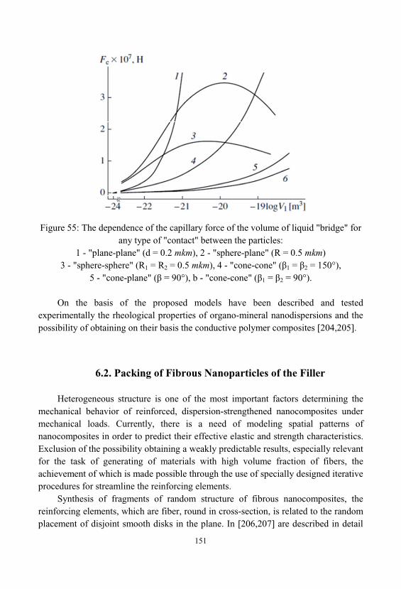
151
Figure 55: The dependence of the capillary force of the volume of liquid "bridge" forany type of "contact" between the particles:
1 - "plane-plane" (d = 0.2 mkm), 2 - "sphere-plane" (R = 0.5 mkm)3 - "sphere-sphere" (R1 = R2 = 0.5 mkm), 4 - "cone-cone" ( 1 = 2 = 150°),
5 - "cone-plane" ( = 90°), b - "cone-cone" ( 1 = 2 = 90°).
On the basis of the proposed models have been described and testedexperimentally the rheological properties of organo-mineral nanodispersions and thepossibility of obtaining on their basis the conductive polymer composites [204,205].
6.2. Packing of Fibrous Nanoparticles of the Filler
Heterogeneous structure is one of the most important factors determining themechanical behavior of reinforced, dispersion-strengthened nanocomposites undermechanical loads. Currently, there is a need of modeling spatial patterns ofnanocomposites in order to predict their effective elastic and strength characteristics. Exclusion of the possibility obtaining a weakly predictable results, especially relevantfor the task of generating of materials with high volume fraction of fibers, theachievement of which is made possible through the use of specially designed iterativeprocedures for streamline the reinforcing elements.
Synthesis of fragments of random structure of fibrous nanocomposites, thereinforcing elements, which are fiber, round in cross-section, is related to the randomplacement of disjoint smooth disks in the plane. In [206,207] are described in detail
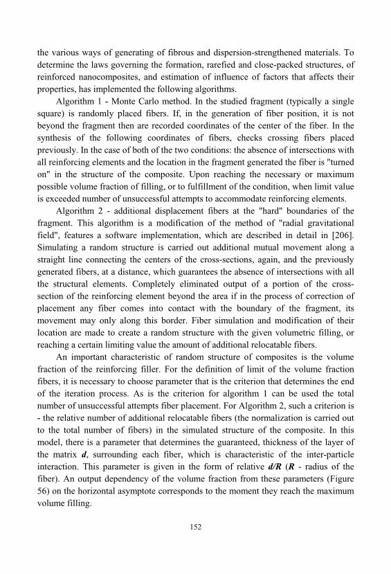
152
the various ways of generating of fibrous and dispersion-strengthened materials. Todetermine the laws governing the formation, rarefied and close-packed structures, ofreinforced nanocomposites, and estimation of influence of factors that affects theirproperties, has implemented the following algorithms.
Algorithm 1 - Monte Carlo method. In the studied fragment (typically a singlesquare) is randomly placed fibers. If, in the generation of fiber position, it is notbeyond the fragment then are recorded coordinates of the center of the fiber. In thesynthesis of the following coordinates of fibers, checks crossing fibers placedpreviously. In the case of both of the two conditions: the absence of intersections withall reinforcing elements and the location in the fragment generated the fiber is "turnedon" in the structure of the composite. Upon reaching the necessary or maximumpossible volume fraction of filling, or to fulfillment of the condition, when limit valueis exceeded number of unsuccessful attempts to accommodate reinforcing elements.
Algorithm 2 - additional displacement fibers at the "hard" boundaries of thefragment. This algorithm is a modification of the method of "radial gravitationalfield", features a software implementation, which are described in detail in [206]. Simulating a random structure is carried out additional mutual movement along astraight line connecting the centers of the cross-sections, again, and the previouslygenerated fibers, at a distance, which guarantees the absence of intersections with allthe structural elements. Completely eliminated output of a portion of the cross-section of the reinforcing element beyond the area if in the process of correction ofplacement any fiber comes into contact with the boundary of the fragment, itsmovement may only along this border. Fiber simulation and modification of theirlocation are made to create a random structure with the given volumetric filling, orreaching a certain limiting value the amount of additional relocatable fibers.
An important characteristic of random structure of composites is the volumefraction of the reinforcing filler. For the definition of limit of the volume fractionfibers, it is necessary to choose parameter that is the criterion that determines the endof the iteration process. As is the criterion for algorithm 1 can be used the totalnumber of unsuccessful attempts fiber placement. For Algorithm 2, such a criterion is- the relative number of additional relocatable fibers (the normalization is carried outto the total number of fibers) in the simulated structure of the composite. In thismodel, there is a parameter that determines the guaranteed, thickness of the layer ofthe matrix d, surrounding each fiber, which is characteristic of the inter-particleinteraction. This parameter is given in the form of relative d/R (R - radius of thefiber). An output dependency of the volume fraction from these parameters (Figure56) on the horizontal asymptote corresponds to the moment they reach the maximumvolume filling.
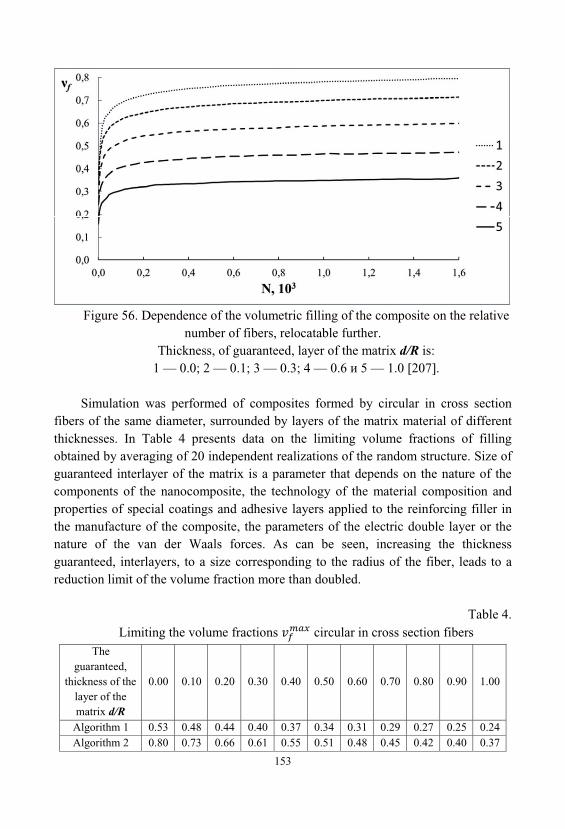
153
Figure 56. Dependence of the volumetric filling of the composite on the relativenumber of fibers, relocatable further.
Thickness, of guaranteed, layer of the matrix d/R is:1 — 0.0; 2 — 0.1; 3 — 0.3; 4 — 0.6 5 — 1.0 [207].
Simulation was performed of composites formed by circular in cross sectionfibers of the same diameter, surrounded by layers of the matrix material of differentthicknesses. In Table 4 presents data on the limiting volume fractions of fillingobtained by averaging of 20 independent realizations of the random structure. Size ofguaranteed interlayer of the matrix is a parameter that depends on the nature of thecomponents of the nanocomposite, the technology of the material composition andproperties of special coatings and adhesive layers applied to the reinforcing filler inthe manufacture of the composite, the parameters of the electric double layer or thenature of the van der Waals forces. As can be seen, increasing the thicknessguaranteed, interlayers, to a size corresponding to the radius of the fiber, leads to areduction limit of the volume fraction more than doubled.
Table 4. Limiting the volume fractions circular in cross section fibers
Theguaranteed,
thickness of thelayer of thematrix d/R
0.00 0.10 0.20 0.30 0.40 0.50 0.60 0.70 0.80 0.90 1.00
Algorithm 1 0.53 0.48 0.44 0.40 0.37 0.34 0.31 0.29 0.27 0.25 0.24Algorithm 2 0.80 0.73 0.66 0.61 0.55 0.51 0.48 0.45 0.42 0.40 0.37
154
In real composites the volume fraction of the reinforcing filler is typically 0,60 ÷0,70, and in highly materials – 0.80 ÷ 0.85. To obtain fragments of random structure, with the volume, degree of filling, exceeding = 0.50, was used by Algorithm 2, in
which, provides an iterative procedure, the additional displacement of the fibers. Itwas found that the value = 0.80 (same cross-sectional fiber without guaranteed
layer) exceeds the highest possible degree of filling of the composite with a periodicarrangement of fibers in the tetragonal grid nodes ( = 0,785). However, it does
not reach the limit of the volume fraction, typical of the material with a periodichexagonal structure ( = 0,907). Recorded values coincides with the value
of the maximum filling, for random dense packings of "smooth" disjoint disks of thesame diameter, obtained by the authors [208].
In these papers were presented data, especially for materials with a high filling, which is particularly important for structural materials. However nanocomposites arealso important low degree of filling of the fibers. Such a calculation was presented in[130].
Comparing the packing of spheres described in the previous section, and thefibers can be represented by the following analogy between openwork packing ofspherical particles, and, fiber packing. If the, chain of bonded spheres represented inthe form as described around them, cylinders, it is possible, in this structure, build arelationship between the average coordination number of spheres, and the ratio offiber diameter and the average distance between the points of contact between twoadjacent unidirectional fibers intersecting and touch the third fiber . For n = 3, = = where -fiber diameter, and for n = 2, = .
Character of packaging of fibrous particles can be determined by the structuralparameter having the form:
(6.6)Tracing the analogy of packing fiber and spherical particles, the effective
coordination number of the packing can be represented as follows:
(6.7)where c - is a constant quantity. From the equation (6.2) of porosity, in Section 6.1., we obtain:
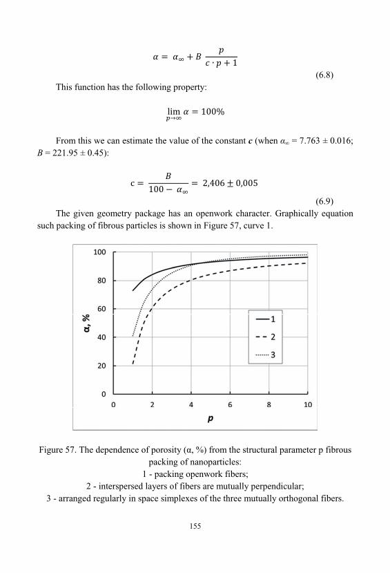
155
(6.8)This function has the following property:
From this we can estimate the value of the constant c (when = 7.763 ± 0.016;B = 221.95 ± 0.45):
(6.9)The given geometry package has an openwork character. Graphically equation
such packing of fibrous particles is shown in Figure 57, curve 1.
Figure 57. The dependence of porosity ( , %) from the structural parameter p fibrouspacking of nanoparticles:
1 - packing openwork fibers;2 - interspersed layers of fibers are mutually perpendicular;
3 - arranged regularly in space simplexes of the three mutually orthogonal fibers.
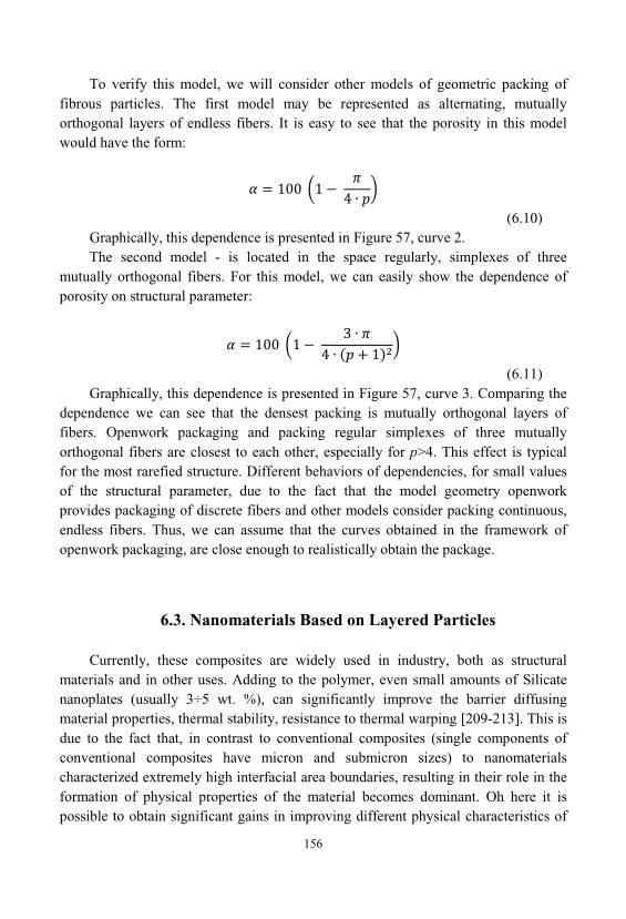
156
To verify this model, we will consider other models of geometric packing offibrous particles. The first model may be represented as alternating, mutuallyorthogonal layers of endless fibers. It is easy to see that the porosity in this modelwould have the form:
(6.10)Graphically, this dependence is presented in Figure 57, curve 2. The second model - is located in the space regularly, simplexes of three
mutually orthogonal fibers. For this model, we can easily show the dependence ofporosity on structural parameter:
(6.11)Graphically, this dependence is presented in Figure 57, curve 3. Comparing the
dependence we can see that the densest packing is mutually orthogonal layers offibers. Openwork packaging and packing regular simplexes of three mutuallyorthogonal fibers are closest to each other, especially for p>4. This effect is typicalfor the most rarefied structure. Different behaviors of dependencies, for small valuesof the structural parameter, due to the fact that the model geometry openworkprovides packaging of discrete fibers and other models consider packing continuous, endless fibers. Thus, we can assume that the curves obtained in the framework ofopenwork packaging, are close enough to realistically obtain the package.
6.3. Nanomaterials Based on Layered Particles
Currently, these composites are widely used in industry, both as structuralmaterials and in other uses. Adding to the polymer, even small amounts of Silicatenanoplates (usually 3÷5 wt. %), can significantly improve the barrier diffusingmaterial properties, thermal stability, resistance to thermal warping [209-213]. This isdue to the fact that, in contrast to conventional composites (single components ofconventional composites have micron and submicron sizes) to nanomaterialscharacterized extremely high interfacial area boundaries, resulting in their role in theformation of physical properties of the material becomes dominant. Oh here it ispossible to obtain significant gains in improving different physical characteristics of
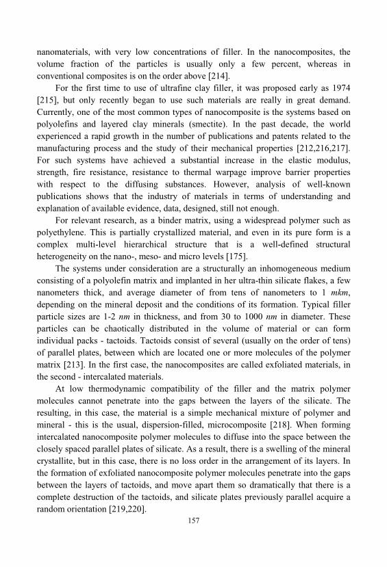
157
nanomaterials, with very low concentrations of filler. In the nanocomposites, thevolume fraction of the particles is usually only a few percent, whereas inconventional composites is on the order above [214].
For the first time to use of ultrafine clay filler, it was proposed early as 1974[215], but only recently began to use such materials are really in great demand. Currently, one of the most common types of nanocomposite is the systems based onpolyolefins and layered clay minerals (smectite). In the past decade, the worldexperienced a rapid growth in the number of publications and patents related to themanufacturing process and the study of their mechanical properties [212,216,217]. For such systems have achieved a substantial increase in the elastic modulus, strength, fire resistance, resistance to thermal warpage improve barrier propertieswith respect to the diffusing substances. However, analysis of well-knownpublications shows that the industry of materials in terms of understanding andexplanation of available evidence, data, designed, still not enough.
For relevant research, as a binder matrix, using a widespread polymer such aspolyethylene. This is partially crystallized material, and even in its pure form is acomplex multi-level hierarchical structure that is a well-defined structuralheterogeneity on the nano-, meso- and micro levels [175].
The systems under consideration are a structurally an inhomogeneous mediumconsisting of a polyolefin matrix and implanted in her ultra-thin silicate flakes, a fewnanometers thick, and average diameter of from tens of nanometers to 1 mkm, depending on the mineral deposit and the conditions of its formation. Typical fillerparticle sizes are 1-2 nm in thickness, and from 30 to 1000 nm in diameter. Theseparticles can be chaotically distributed in the volume of material or can formindividual packs - tactoids. Tactoids consist of several (usually on the order of tens)of parallel plates, between which are located one or more molecules of the polymermatrix [213]. In the first case, the nanocomposites are called exfoliated materials, inthe second - intercalated materials.
At low thermodynamic compatibility of the filler and the matrix polymermolecules cannot penetrate into the gaps between the layers of the silicate. Theresulting, in this case, the material is a simple mechanical mixture of polymer andmineral - this is the usual, dispersion-filled, microcomposite [218]. When formingintercalated nanocomposite polymer molecules to diffuse into the space between theclosely spaced parallel plates of silicate. As a result, there is a swelling of the mineralcrystallite, but in this case, there is no loss order in the arrangement of its layers. Inthe formation of exfoliated nanocomposite polymer molecules penetrate into the gapsbetween the layers of tactoids, and move apart them so dramatically that there is acomplete destruction of the tactoids, and silicate plates previously parallel acquire arandom orientation [219,220].
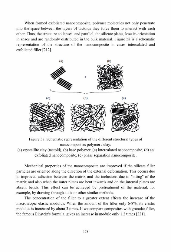
158
When formed exfoliated nanocomposite, polymer molecules not only penetrateinto the space between the layers of tactoids they force them to interact with eachother. Thus, the structure collapses, and parallel, the silicate plates, lose its orientationin space and are randomly distributed in the bulk material. Figure 58 is a schematicrepresentation of the structure of the nanocomposite in cases intercalated andexfoliated filler [212].
Figure 58. Schematic representation of the different structural types ofnanocomposites polymer / clay:
(a) crystallite clay (tactoid), (b) base polymer, (c) intercalated nanocomposite, (d) anexfoliated nanocomposite, (e) phase separation nanocomposite.
Mechanical properties of the nanocomposite are improved if the silicate fillerparticles are oriented along the direction of the external deformation. This occurs dueto improved adhesion between the matrix and the inclusions due to "biting" of thematrix and also when the outer plates are bent inwards and on the internal plates areabsent bends. This effect can be achieved by pretreatment of the material, forexample, by drawing through a die or other similar methods.
The concentration of the filler to a greater extent affects the increase of themacroscopic elastic modulus. When the amount of the filler only 6-8%, its elasticmodulus is increased by about 3 times. If we compare composites with granular filler, the famous Einstein's formula, gives an increase in module only 1.2 times [221].
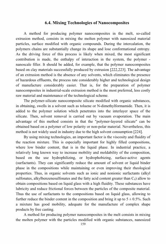
159
6.4. Mixing Technologies of Nanocomposites
A method for producing polymer nanocomposites in the melt, so-calledextrusion method, consists in mixing the molten polymer with nanosized materialparticles, surface modified with organic compounds. During the intercalation, thepolymers chains are substantially change its shape and lose conformational entropy. As the driving force of this process is likely when mixed, the most significantcontribution is made, the enthalpy of interaction in the system, the polymer -nanoscale filler. It should be added, for example, that the polymer nanocompositesbased on clay materials successfully produced by extrusion [222,223]. The advantageof an extrusion method is the absence of any solvents, which eliminates the presenceof hazardous effluents, the process rate considerably higher and technological designof manufacture considerably easier. That is, for the preparation of polymernanocomposites in industrial-scale extrusion method is the most preferred, less costlyraw material and maintenance of the technological scheme.
The polymer-silicate nanocomposite silicate modified with organic substances, in obtaining, swells in a solvent such as toluene or N-dimethylformamide. Then, it isadded to the polymer solution which penetrates into the interlayer space of thesilicate. Then, solvent removal is carried out by vacuum evaporation. The mainadvantage of this method consists in that the "polymer-layered silicate" can beobtained based on a polymer of low polarity or non-polar material. Nevertheless, thismethod is not widely used in industry due to the high solvent consumption [224].
By using mixing technologies, an important factor is the viscosity and fluidity ofthe reaction mixture. This is especially important for highly filled compositions, where low binder content, that is in the liquid phase. In industrial practice, arelatively long known way to increase mobility and moldability of the composition, based on the use hydrophilizing, or hydrophobizing, surface-active agents(surfactants). They can significantly reduce the amount of solvent or liquid binderphase in the compositions while maintaining or even improving their rheologicalproperties. Thus, in organic solvents such as ionic and nonionic surfactants (alkylsulfonates, alkylbenzenesulfonates and the fatty acid content greater than C9) allow toobtain compositions based on liquid glass with a high fluidity. These substances havelubricity and reduce frictional forces between the particles of the composite material. Thus the use of surfactants to the compositions based on liquid glass, allowing tofurther reduce the binder content in the composition and bring it up to 5 ± 0.5%. Sucha mixture has good mobility, adequate for the manufacture of complex shapeproducts by free casting.
A method for producing polymer nanocomposites in the melt consists in mixingthe molten polymer with the particles modified with organic substances, nanosized
160
dispersed material. Preparation of polymer nanocomposites such as clay filler in thesynthesis of the polymer is the intercalation of the monomer in the clay layers. Monomer migrates through the galleries organo-clay material and polymerizationtakes place within the layers. The polymerization reaction may be initiated byheating, irradiation or appropriate initiator [225].
The nature of the rheological properties of the compositions is influenced byvarious factors - the size of the starting particle agglomerates; microstructures formedby them; forces acting between the particles and contribute to the formation ofagglomerates; processes that take place in a structured composition on flowing. Afterhaving been applied shear forces, macroscopic agglomerates of filler destroyed in thefirst place, this is reflected in the results of rheological measurements. Transitionalperiod, corresponding to the period of time from the beginning of the destruction ofmacroscopic agglomerates until the equilibrium, is characterized by a gradual changein the intensity of the scattered light. In the systems studied, the destruction of theagglomerates, to form separate particles, and their stable compounds, and to achievetheir uniform distribution in volume of binder was confirmed by microscopicobservation of samples dispersion compositions [204].
Particles of fine filler are also capable of forming a continuous structure, penetrating the entire volume of the system and lead to changes in the macroscopicproperties of the oligomeric composition. Primarily it is an increase energydissipation during flow, and hence the change of rheological properties, namely toincrease the viscosity of the composition. In case of use, electrically conductive fillersuch as carbon black, when creating continuous spatial structures will happensignificantly change of the properties of the composition, the material becomeselectrically conductive. Obviously, the length of the continuous chains must becommensurate with the distance between the electrodes. Consequently, theconductivity of filled compositions is more sensitive parameter creation processcontinuous spatial structures of particles than the viscosity of the composition. Thesharp increase in viscosity appears to occur during the formation of the localstructures of the filler particles. The dimensions of such structural formations notcommensurate with the size of the space between the electrodes, hence, thecomposite retains dielectric properties.
Thus, to obtain conductive compositions on the basis of highly dispersed;components necessary to construct chains of particle sizes which are many ordersexceed the sizes of the particles themselves, and the number of particles in the chainof thousands or tens of thousands. It is obvious that such complex associates easilysusceptible to damage. Possible to assume that these large particles, in turn, couldbecome centers of structure formation carbon black particles. Dimensions of
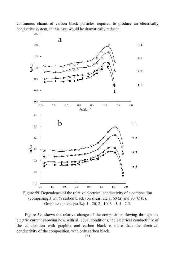
161
continuous chains of carbon black particles required to produce an electricallyconductive system, in this case would be dramatically reduced.
Figure 59. Dependence of the relative electrical conductivity of a composition(comprising 3 wt. % carbon black) on shear rate at 60 (a) and 80 °C (b).
Graphite content (wt.%): 1 - 20, 2 - 10, 3 - 5, 4 - 2.5.
Figure 59, shows the relative change of the composition flowing through theelectric current showing how with all equal conditions, the electrical conductivity ofthe composition with graphite and carbon black is more than the electricalconductivity of the composition, with only carbon black.
162
These studies showed that introduction in oligomer 22 wt.% graphite does notproduce electrical conductivity of the test composition, but an oligomer containing 3wt.% carbon black has conductive properties (Figure 59 a). However, theintroduction of graphite into the composition containing 3 wt. % carbon black, leadsto a sharp increase in the electrical conductivity of the whole system. The increase ofthe shear rate leads to the destruction of the internal structure of the composition andreduction of its electrical conductivity. Figure 59-b, shows similar curves for elevatedtemperature. As follows from the data presented the effect of graphite increases withincreasing shear rate. The maximum effect of graphite at a temperature of 60 °Ccorresponds to a shear rate of 10 s-1. Increasing the temperature to 80 °C, leads to anincrease in this value to a shear rate, approximately, 20 s-1 [205].
6.5. Fractal and Hierarchical Structure of NanostructuredComposite Materials
Gels are the foundation of the structure of nanostructured silica compositematerials. The silica gel in its structure is a system of interconnected solid particles, and the volume occupied by the particles is a small fraction of the volume of the gel. Almost the entire volume is necessary to void - the pores. The characteristic size ofthe individual particles that make up of silica gel, typically of the order of 2 ÷ 200nm. The simplest model of the gel can be constructed from spherical particles of thesame size, and the relationship between them is where the particles are almosttouching each other. Any piece of gel comprising a large number of individualparticles in this model represents the fractal cluster [331].
Such a structure is determined by the mechanism of gel formation, the growth ofwhich is due to the sticking of individual particles moving in the solution to formgrowing aggregates. In accordance with one of the characteristics of a fractalaggregate, the average mass density of the material in the sphere of radius R is equalto:
(6.12)- density of the particle material constituting the aggregate; - the average
radius of the particles formed aggregate, - the fractal dimension of the aggregate.
Presented dependence means that with growth of the selected volume, in it will be
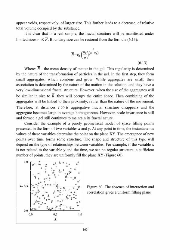
163
appear voids, respectively, of larger size. This further leads to a decrease, of relativetotal volume occupied by the substance.
It is clear that in a real sample, the fractal structure will be manifested under
limited sizes . Boundary size can be restored from the formula (6.13):
(6.13)
Where: - the mean density of matter in the gel. This regularity is determinedby the nature of the transformation of particles in the gel. In the first step, they formsmall aggregates, which combine and grow. While aggregates are small, theirassociation is determined by the nature of the motion in the solution, and they have avery low-dimensional fractal structure. However, when the size of the aggregates will
be similar in size to , they will occupy the entire space. Then combining of theaggregates will be linked to their proximity, rather than the nature of the movement.
Therefore, at distances aggregative fractal structure disappears and theaggregate becomes large in average homogeneous. However, scale invariance is stilland formed a gel still continues to maintain its fractal nature.
Consider the example of a purely geometrical model of space filling pointspresented in the form of two variables x and y. At any point in time, the instantaneousvalues of these variables determine the point on the plane XY. The emergence of newpoints over time forms some structure. The shape and structure of this type willdepend on the type of relationships between variables. For example, if the variable xis not related to the variable y and the time, we see no regular structure: a sufficientnumber of points, they are uniformly fill the plane XY (Figure 60).
Figure 60. The absence of interaction andcorrelation gives a uniform filling plane
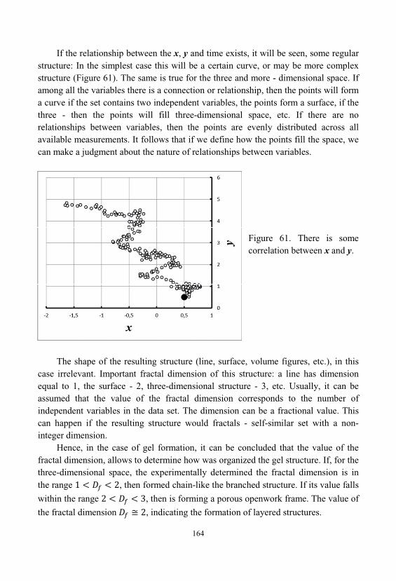
164
If the relationship between the x, y and time exists, it will be seen, some regularstructure: In the simplest case this will be a certain curve, or may be more complexstructure (Figure 61). The same is true for the three and more - dimensional space. Ifamong all the variables there is a connection or relationship, then the points will forma curve if the set contains two independent variables, the points form a surface, if thethree - then the points will fill three-dimensional space, etc. If there are norelationships between variables, then the points are evenly distributed across allavailable measurements. It follows that if we define how the points fill the space, wecan make a judgment about the nature of relationships between variables.
Figure 61. There is somecorrelation between x and y.
The shape of the resulting structure (line, surface, volume figures, etc.), in thiscase irrelevant. Important fractal dimension of this structure: a line has dimensionequal to 1, the surface - 2, three-dimensional structure - 3, etc. Usually, it can beassumed that the value of the fractal dimension corresponds to the number ofindependent variables in the data set. The dimension can be a fractional value. Thiscan happen if the resulting structure would fractals - self-similar set with a non-integer dimension.
Hence, in the case of gel formation, it can be concluded that the value of thefractal dimension, allows to determine how was organized the gel structure. If, for thethree-dimensional space, the experimentally determined the fractal dimension is inthe range , then formed chain-like the branched structure. If its value falls
within the range , then is forming a porous openwork frame. The value of
the fractal dimension , indicating the formation of layered structures.
165
We define the possible values for the fractal dimension during the formation ofgels from the silica sols. The equations (6.12) and (6.13), given above reduce to therelation (4.99) (4.134), presented earlier. For calculations it is more convenient to useequation (4.99) (4.134), which binds the properties of sols with fractal dimension ofgels that are formed during the synthesis. We represent this equation in the followingform:
(6.14)Here, n - the number of monodisperse particles in the sphere with a diameter, that is, within the sphere circumscribed around one of the forming aggregates.
In the case of the formation of an infinite aggregate, corresponds to the size of
the entire system. – the particle diameter of the sol. – fractal dimension.
In order to evaluate which the maximum value of the fractal dimension can beformed in the sol with a given mass concentration of particles (M) in a volume ofdiameter and given mass of a single particle of sol ( ), write down the
expression for the calculation of the number of particles in a unit volume of the sol. After substitution of values of the relevant parameters we obtain:
(6.15)Where: m - the mass concentration of the sol. – particle density of sol
substance. Combining equations (6.14) and (6.15)we obtain:
(6.16)This equation is very similar to the equation (6.12). However, the equation
(6.16), unlike the equation (6.12) does not describe the structure of the gel beenformed. It describes the asymptotic structure that can be formed from this sol, in theprocess of gelation. Thus, it describes the asymptotic structure of the fractaldimension, above which no other structure cannot be formed from the sol with thedesired properties. That is, it is the fractal dimension, to which seeks the gel structure
166
in the process of aggregation of the sol and forming a gel structure after passing thepoint of the sol-gel transition:
(6.17)Thus, fractal dimension may be different for one and the same system at
different scales and at different time points. This is also clearly seen from equation(4.112) (4.147), and curve 2 in Figure 43
. From these data it is seen that by the moment of gelation, only about half of theparticles of the sol included in the structure of infinite aggregate formed by thisprocess. That is the fractal dimension of the gel at the time of gelation, has not yetreached the critical value, which will be formed at the gel - the equation (6.17).
Thus, from equation (6.16), we can obtain an equation describing thedependence of the limiting value of the fractal dimension of the gel structure, whichcan be formed from this sol:
(6.18)The results of calculations carried out by the equation (6.18) for the sols with
different particle sizes and different mass concentration, are presented in Figures 62and 63.
Previously, in section 6.1, was demonstrated relationship porosity packing ofspherical particles in a globular structure, depending on the coordination number ofthese particles. Therefore, using the equations given in Section 6.1, in particular theequation (6.15) and (6.18), we can calculate the dependence of the limiting value ofthe fractal dimension , the coordination number of particles in globular package.
The results of these calculations for particles with different diameters are shown inFigures 64 and 65.
The obtained results, on the relationship of the structural parameters of gels donot only apply to freshly prepared wet gel, but also to materials passed syneresis anddrying. From, Figure 64 shows that of coordination numbers from 3 to 12, there isalmost a direct correlation between the coordination number of particles in thestructure and its fractal dimension. At the time when the coordination number lessthan 2.5, its value has almost no effect on the fractal dimension of the emergingstructure.
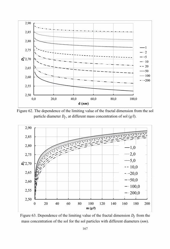
167
Figure 62. The dependence of the limiting value of the fractal dimension from the solparticle diameter , at different mass concentration of sol (g/l).
Figure 63. Dependence of the limiting value of the fractal dimension from the
mass concentration of the sol for the sol particles with different diameters (nm).
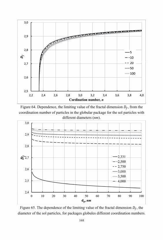
168
Figure 64. Dependence, the limiting value of the fractal dimension , from the
coordination number of particles in the globular package for the sol particles withdifferent diameters (nm).
Figure 65. The dependence of the limiting value of the fractal dimension , the
diameter of the sol particles, for packages globules different coordination numbers.
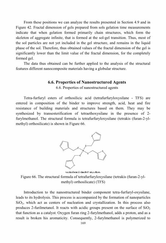
169
From these positions we can analyze the results presented in Section 4.9 and inFigure 42. Fractal dimension of gels prepared from sols gelation time measurementsindicate that when gelation formed primarily chain structures, which form theskeleton of aggregate infinite, that is formed at the sol-gel transition. Thus, most ofthe sol particles are not yet included in the gel structure, and remains in the liquidphase of the sol. Therefore, thus obtained values of the fractal dimension of the gel issignificantly lower than the limit value of the fractal dimension, for the completelyformed gel.
The data thus obtained can be further applied to the analysis of the structuralfeatures different nanocomposite materials having a globular structure.
6.6. Properties of Nanostructured Agents6.6. Properties of nanostructured agents
Tetra-furfuryl esters of orthosilicic acid (tetrafurfuryloxysilane - TFS) areentered in composition of the binder to improve strength, acid, heat and fireresistance of building materials and structures based on them. They may besynthesized by transesterification of tetraethoxysilane in the presence of 2-furylmethanol. The structural formula is tetrafurfuryloxysilane (tetrakis (furan-2-yl-methyl) orthosilicate) is shown in Figure 66.
Figure 66. The structural formula of tetrafurfuryloxysilane (tetrakis (furan-2-yl-methyl) orthosilicate) (TFS)
Introduction to the nanostructured binder component tetra-furfuryl-oxysilane, leads to its hydrolysis. This process is accompanied by the formation of nanoparticlesSiO2, which act as centers of nucleation and crystallization. In this process alsoproduces 2-furilmetanol. It reacts with acidic groups present on the surface of SiO2
that function as a catalyst. Oxygen furan ring 2-furylmethanol, adds a proton, and as aresult is broken his aromaticity. Consequently, 2-furylmethanol is polymerized to
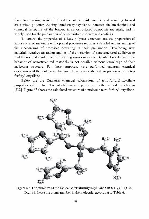
170
form furan resins, which is filled the silicic oxide matrix, and resulting formedcrosslinked polymer. Adding tetrafurfuryloxysilane, increases the mechanical andchemical resistance of the binder, in nanostructured composite materials, and iswidely used for the preparation of acid-resistant concrete and coatings.
To control the properties of silicate polymer concretes and the preparation ofnanostructured materials with optimal properties requires a detailed understanding ofthe mechanisms of processes occurring in their preparation. Developing newmaterials requires an understanding of the behavior of nanostructured additives tofind the optimal conditions for obtaining nanocomposites. Detailed knowledge of thebehavior of nanostructured materials is not possible without knowledge of theirmolecular structure. For these purposes, were performed quantum chemicalcalculations of the molecular structure of used materials, and, in particular, for tetra-furfuryl-oxysilane.
Below are the Quantum chemical calculations of tetra-furfuryl-oxysilaneproperties and structure. The calculations were performed by the method described in[332]. Figure 67 shows the calculated structure of a molecule tetra-furfuryl-oxysilane.
Figure 67. The structure of the molecule tetrafurfuryloxysilane Si(OCH2(C4H3O))4. Digits indicate the atoms number in the molecule, according to Table 6.
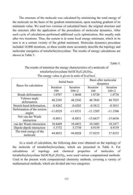
171
The structure of the molecule was calculated by minimizing the total energy ofthe molecule on the basis of the gradient minimization, upon reaching gradient of itsminimum value. We used two versions of calculated basis: the original structure andthe structure after the application of the procedures of molecular dynamics. Aftereach cycle of calculations performed additional cycle optimization, this usually endsafter two iterations. Thus, the system is in some local energy minimum, which in itsturn is in a certain vicinity of the global minimum. Molecular dynamics procedureincluded 10,000 iterations, so these results more accurately describe the topology andmolecular energetics of tetrafurfuryloxysilane. The results of energy calculations areshown in Table 5.
Table 5. The results of minimize the energy characteristics of a molecule of
tetrafurfuryloxysilane Si(OCH2(C4H3O))4. The energy value is given in units of kcal/mol.
Bases for calculationInitial basis
Basis after moleculardynamics
Iteration599
Iteration599+2
Iteration189
Iteration189+2
Bonds deformation 1.0707 1.0648 1.0720 1.0738Valence angledeformation
48.2545 48.2542 48.7845 48.7835
Stretch-bend deformation, -0.4262 -0.4203 -0.3812 -0.3815Deformation of the torsion
angles-11.0329 -11.0331 -11.1505 -11.1506
Not van der Waalsinteraction
-8.8831 -8.8831 -15.6637 -15.6636
van der Waals interaction 10.4449 10.4452 10.2485 10.2477Dipole-dipole interaction 5.3752 5.3750 4.9159 4.9159The total energy of the
molecule44.8032 44.8028 37.8255 37.8252
As a result of calculation, the following data were obtained on the topology ofthe molecule of tetrafurfuryloxysilane, which are presented in Table 6. Forcalculations of topology and chemical properties of molecules oftetrafurfuryloxysilane Si(OCH2(C4H3O))4, were used various computational methods. Used in the present work computational chemistry methods, covering a variety ofmathematical methods, which are divided into two categories:
172
• Molecular mechanics - applies the laws of classical physics to the atoms in themolecule without explicit consideration of the electrons. For these calculations, weused the method MM2 and MMFF94.
• Quantum mechanics - based on the Schrödinger equation for the description ofa molecule with an explicit treatment of the electronic structure. In its turn thequantum-mechanical methods can be divided into two classes: Ab initio (non-empirical) and semi-empirical. In Ab initio method was used the process GAMESSInterface - The General Atomic and Molecular Electronic Structure System. Forthe implementation of semiempirical methods of calculations was used Huckeldeployed method.
For this molecule were calculated atomic charges, which have been obtainedfrom electrostatic potentials. These data provide valuable information about thechemical activity. For example, the atomic point charges give a better understandingof the likely locations of attack by chemical interaction of the molecule with externalagents. The results of these calculations are presented in Table 7.
These results indicate functional irregularity of furfuryl-oxide groups. This, inturn, points to the possibility of interactions between molecules stepwise mechanismof tetra-furfuryl-oxysilane as between themselves and with the surroundingmolecules. Besides, the molecule of tetrafurfuryloxysilane is not symmetrical, whichalso provides the possibility of stepwise mechanism for the formation of nanoscalephases and nanostructuring of silicate polymer concrete in its preparation.
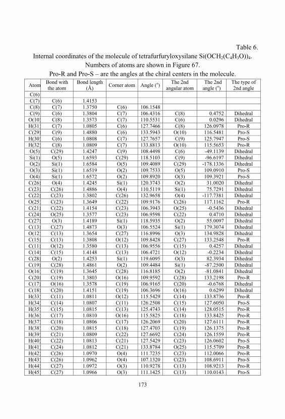
173
Table 6. Internal coordinates of the molecule of tetrafurfuryloxysilane Si(OCH2(C4H3O))4.
Numbers of atoms are shown in Figure 67. Pro-R and Pro-S – are the angles at the chiral centers in the molecule.
AtomBond withthe atom
Bond length(Å)
Corner atom Angle (o)The 2nd
angular atomThe 2nd
angle (o)The type of2nd angle
C(6) C(7) C(6) 1.4153 C(8) C(7) 1.3750 C(6) 106.1548 C(9) C(6) 1.3804 C(7) 106.4316 C(8) 0.4752 Dihedral
O(10) C(8) 1.3573 C(7) 110.5531 C(6) 0.0296 DihedralH(31) C(7) 1.0805 C(6) 127.7466 C(8) 126.0978 Pro-RC(29) C(9) 1.4880 C(6) 133.5943 O(10) 116.5481 Pro-SH(30) C(6) 1.0808 C(7) 127.7657 C(9) 125.7947 Pro-SH(32) C(8) 1.0809 C(7) 133.8813 O(10) 115.5653 Pro-RO(5) C(29) 1.4247 C(9) 108.4498 C(6) -49.1139 DihedralSi(1) O(5) 1.6593 C(29) 118.5103 C(9) -96.6197 DihedralO(2) Si(1) 1.6584 O(5) 109.4089 C(29) -178.1336 DihedralO(3) Si(1) 1.6519 O(2) 109.7533 O(5) 109.0910 Pro-SO(4) Si(1) 1.6572 O(2) 109.8920 O(3) 109.3921 Pro-SC(26) O(4) 1.4245 Si(1) 120.3743 O(2) 31.0020 DihedralC(23) C(26) 1.4886 O(4) 110.5119 Si(1) 75.7291 DihedralC(22) C(23) 1.3802 C(26) 132.9658 O(4) -117.7381 DihedralO(25) C(23) 1.3649 C(22) 109.9176 C(26) 117.1162 Pro-RC(21) C(22) 1.4154 C(23) 106.3943 O(25) -0.5436 DihedralC(24) O(25) 1.3577 C(23) 106.9598 C(22) 0.4710 DihedralC(27) O(3) 1.4189 Si(1) 118.5935 O(2) 55.0097 DihedralC(13) C(27) 1.4873 O(3) 106.5524 Si(1) 179.3074 DihedralO(12) C(13) 1.3654 C(27) 116.8996 O(3) 134.9828 DihedralC(15) C(13) 1.3808 O(12) 109.8428 C(27) 133.2548 Pro-RC(11) O(12) 1.3580 C(13) 106.9556 C(15) 0.4257 DihedralC(14) C(15) 1.4148 C(13) 106.4721 O(12) -0.2234 DihedralC(28) O(2) 1.4253 Si(1) 119.6095 O(3) 82.3934 DihedralC(19) C(28) 1.4861 O(2) 109.4484 Si(1) -87.2500 DihedralO(16) C(19) 1.3645 C(28) 116.8185 O(2) -81.0841 DihedralC(20) C(19) 1.3803 O(16) 109.9592 C(28) 133.2198 Pro-RC(17) O(16) 1.3578 C(19) 106.9165 C(20) -0.6768 DihedralC(18) C(20) 1.4151 C(19) 106.3696 O(16) 0.6299 DihedralH(33) C(11) 1.0811 O(12) 115.5429 C(14) 133.8736 Pro-RH(34) C(14) 1.0807 C(11) 126.2508 C(15) 127.6050 Pro-SH(35) C(15) 1.0815 C(13) 125.4743 C(14) 128.0515 Pro-RH(36) C(17) 1.0810 O(16) 115.5825 C(18) 133.8425 Pro-RH(37) C(18) 1.0806 C(17) 126.2069 C(20) 127.6111 Pro-RH(38) C(20) 1.0815 C(18) 127.4703 C(19) 126.1375 Pro-RH(39) C(21) 1.0809 C(22) 127.6692 C(24) 126.1559 Pro-RH(40) C(22) 1.0813 C(21) 127.5429 C(23) 126.0602 Pro-SH(41) C(24) 1.0812 C(21) 133.8784 O(25) 115.5709 Pro-RH(42) C(26) 1.0970 O(4) 111.7235 C(23) 112.0066 Pro-RH(43) C(26) 1.0962 O(4) 107.1320 C(23) 108.6911 Pro-SH(44) C(27) 1.0972 O(3) 110.9278 C(13) 108.9213 Pro-RH(45) C(27) 1.0966 O(3) 111.1425 C(13) 110.0143 Pro-S
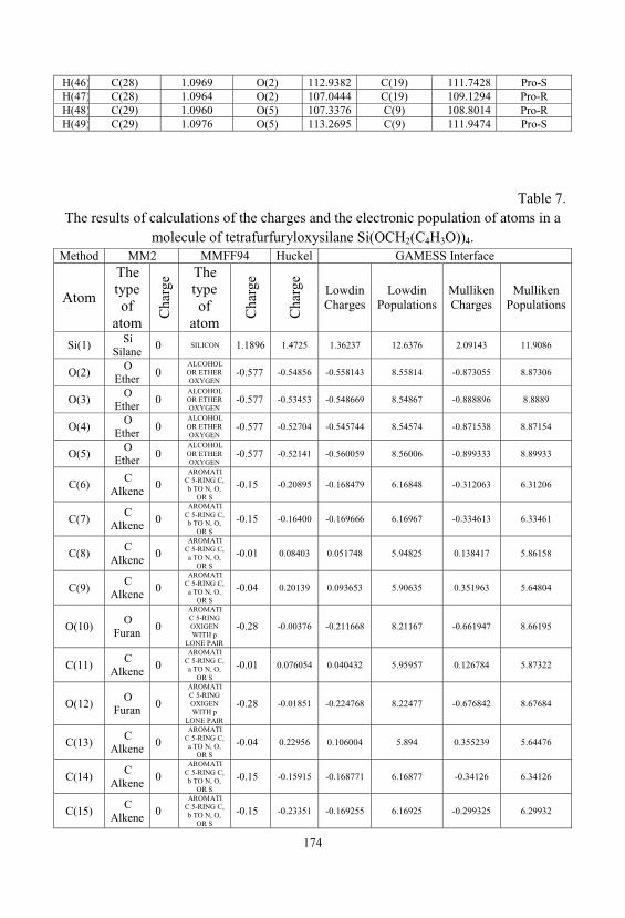
174
H(46) C(28) 1.0969 O(2) 112.9382 C(19) 111.7428 Pro-SH(47) C(28) 1.0964 O(2) 107.0444 C(19) 109.1294 Pro-RH(48) C(29) 1.0960 O(5) 107.3376 C(9) 108.8014 Pro-RH(49) C(29) 1.0976 O(5) 113.2695 C(9) 111.9474 Pro-S
Table 7. The results of calculations of the charges and the electronic population of atoms in a
molecule of tetrafurfuryloxysilane Si(OCH2(C4H3O))4. Method MM2 MMFF94 Huckel GAMESS Interface
Atom
Thetypeof
atom
Cha
rge The
typeof
atom
Cha
rge
Cha
rge
LowdinCharges
LowdinPopulations
MullikenCharges
MullikenPopulations
Si(1)Si
Silane0 SILICON 1.1896 1.4725 1.36237 12.6376 2.09143 11.9086
O(2)O
Ether0
ALCOHOLOR ETHEROXYGEN
-0.577 -0.54856 -0.558143 8.55814 -0.873055 8.87306
O(3)O
Ether0
ALCOHOLOR ETHEROXYGEN
-0.577 -0.53453 -0.548669 8.54867 -0.888896 8.8889
O(4)O
Ether0
ALCOHOLOR ETHEROXYGEN
-0.577 -0.52704 -0.545744 8.54574 -0.871538 8.87154
O(5)O
Ether0
ALCOHOLOR ETHEROXYGEN
-0.577 -0.52141 -0.560059 8.56006 -0.899333 8.89933
C(6)C
Alkene0
AROMATIC 5-RING C, b TO N, O,
OR S
-0.15 -0.20895 -0.168479 6.16848 -0.312063 6.31206
C(7)C
Alkene0
AROMATIC 5-RING C, b TO N, O,
OR S
-0.15 -0.16400 -0.169666 6.16967 -0.334613 6.33461
C(8)C
Alkene0
AROMATIC 5-RING C, a TO N, O,
OR S
-0.01 0.08403 0.051748 5.94825 0.138417 5.86158
C(9)C
Alkene0
AROMATIC 5-RING C, a TO N, O,
OR S
-0.04 0.20139 0.093653 5.90635 0.351963 5.64804
O(10)O
Furan0
AROMATIC 5-RINGOXIGENWITH p
LONE PAIR
-0.28 -0.00376 -0.211668 8.21167 -0.661947 8.66195
C(11)C
Alkene0
AROMATIC 5-RING C, a TO N, O,
OR S
-0.01 0.076054 0.040432 5.95957 0.126784 5.87322
O(12)O
Furan0
AROMATIC 5-RINGOXIGENWITH p
LONE PAIR
-0.28 -0.01851 -0.224768 8.22477 -0.676842 8.67684
C(13)C
Alkene0
AROMATIC 5-RING C, a TO N, O,
OR S
-0.04 0.22956 0.106004 5.894 0.355239 5.64476
C(14)C
Alkene0
AROMATIC 5-RING C, b TO N, O,
OR S
-0.15 -0.15915 -0.168771 6.16877 -0.34126 6.34126
C(15)C
Alkene0
AROMATIC 5-RING C, b TO N, O,
OR S
-0.15 -0.23351 -0.169255 6.16925 -0.299325 6.29932
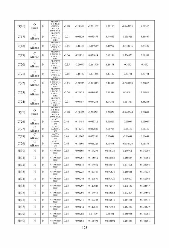
175
O(16)O
Furan0
AROMATIC 5-RINGOXIGENWITH p
LONE PAIR
-0.28 -0.00309 -0.211132 8.21113 -0.663125 8.66313
C(17)C
Alkene0
AROMATIC 5-RING C, a TO N, O,
OR S
-0.01 0.08520 0.053473 5.94653 0.135915 5.86409
C(18)C
Alkene0
AROMATIC 5-RING C, b TO N, O,
OR S
-0.15 -0.16480 -0.169669 6.16967 -0.333216 6.33322
C(19)C
Alkene0
AROMATIC 5-RING C, a TO N, O,
OR S
-0.04 0.20131 0.078614 5.92139 0.334033 5.66597
C(20)C
Alkene0
AROMATIC 5-RING C, b TO N, O,
OR S
-0.15 -0.20697 -0.161779 6.16178 -0.3092 6.3092
C(21)C
Alkene0
AROMATIC 5-RING C, b TO N, O,
OR S
-0.15 -0.16487 -0.171865 6.17187 -0.33741 6.33741
C(22)C
Alkene0
AROMATIC 5-RING C, b TO N, O,
OR S
-0.15 -0.20973 -0.165915 6.16592 -0.308128 6.30813
C(23)C
Alkene0
AROMATIC 5-RING C, a TO N, O,
OR S
-0.04 0.20425 0.084057 5.91594 0.33081 5.66919
C(24)C
Alkene0
AROMATIC 5-RING C, a TO N, O,
OR S
-0.01 0.08487 0.054238 5.94576 0.137517 5.86248
O(25)O
Furan0
AROMATIC 5-RINGOXIGENWITH p
LONE PAIR
-0.28 -0.00552 -0.208741 8.20874 -0.660044 8.66004
C(26)C
Alkane0
ALKYLCARBON,
SP30.46 0.10484 0.083711 5.91629 -0.05909 6.05909
C(27)C
Alkane0
ALKYLCARBON,
SP30.46 0.11275 0.082839 5.91716 -0.06319 6.06319
C(28)C
Alkane0
ALKYLCARBON,
SP30.46 0.10767 0.073556 5.92644 -0.09444 6.09444
C(29)C
Alkane0
ALKYLCARBON,
SP30.46 0.10108 0.085224 5.91478 -0.058726 6.05873
H(30) H 0H
ATTACHEDTO C
0.15 0.03195 0.114274 0.885726 0.249995 0.750005
H(31) H 0H
ATTACHEDTO C
0.15 0.03267 0.115012 0.884988 0.250834 0.749166
H(32) H 0H
ATTACHEDTO C
0.15 0.02178 0.114952 0.885048 0.271605 0.728395
H(33) H 0H
ATTACHEDTO C
0.15 0.02235 0.109169 0.890831 0.260665 0.739335
H(34) H 0H
ATTACHEDTO C
0.15 0.03240 0.109579 0.890421 0.239807 0.760193
H(35) H 0H
ATTACHEDTO C
0.15 0.03297 0.127023 0.872977 0.275153 0.724847
H(36) H 0H
ATTACHEDTO C
0.15 0.02204 0.114916 0.885084 0.272404 0.727596
H(37) H 0H
ATTACHEDTO C
0.15 0.03241 0.117384 0.882616 0.254585 0.745415
H(38) H 0H
ATTACHEDTO C
0.15 0.03172 0.120537 0.879463 0.263361 0.736639
H(39) H 0H
ATTACHEDTO C
0.15 0.03268 0.11509 0.88491 0.250935 0.749065
H(40) H 0H
ATTACHEDTO C
0.15 0.03164 0.116498 0.883502 0.254839 0.745161
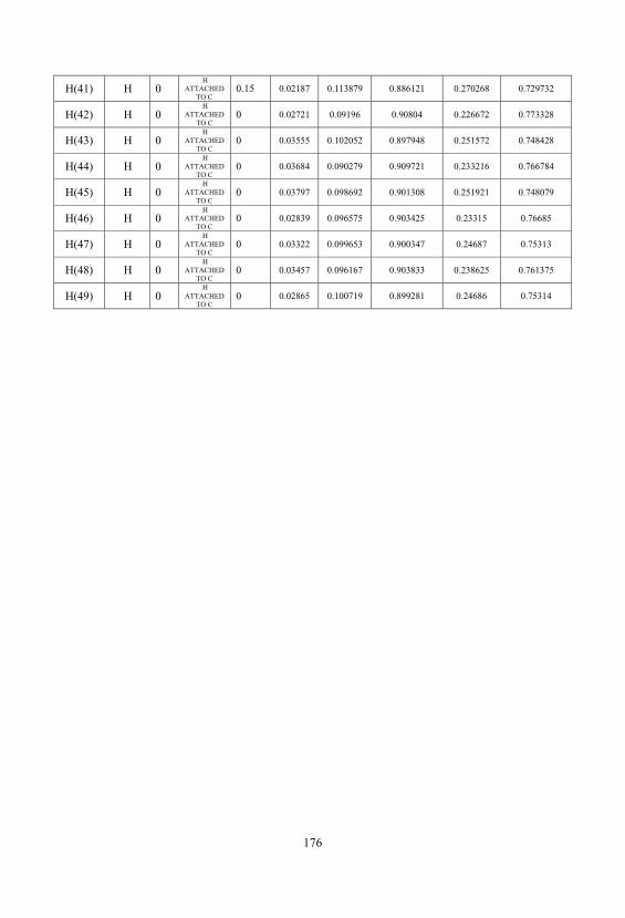
176
H(41) H 0H
ATTACHEDTO C
0.15 0.02187 0.113879 0.886121 0.270268 0.729732
H(42) H 0H
ATTACHEDTO C
0 0.02721 0.09196 0.90804 0.226672 0.773328
H(43) H 0H
ATTACHEDTO C
0 0.03555 0.102052 0.897948 0.251572 0.748428
H(44) H 0H
ATTACHEDTO C
0 0.03684 0.090279 0.909721 0.233216 0.766784
H(45) H 0H
ATTACHEDTO C
0 0.03797 0.098692 0.901308 0.251921 0.748079
H(46) H 0H
ATTACHEDTO C
0 0.02839 0.096575 0.903425 0.23315 0.76685
H(47) H 0H
ATTACHEDTO C
0 0.03322 0.099653 0.900347 0.24687 0.75313
H(48) H 0H
ATTACHEDTO C
0 0.03457 0.096167 0.903833 0.238625 0.761375
H(49) H 0H
ATTACHEDTO C
0 0.02865 0.100719 0.899281 0.24686 0.75314
177
7. PERSPECTIVE DIRECTIONS OF APPLICATION OFLIQUID GLASS AND WATER SOLUTIONS OF HIGHMODULUS OF SILICATES IN CONSTRUCTION AND
INDUSTRY
7.1. The Use of Liquid Glass and Water Solutions of Silicates inthe Rocket-Space Technology
Scientific and technical progress is associated with the development and broadintroduction of new structural materials, among them the important place occupied byfibrous composite materials. The continuous power winding – is one of the mostcommon and highly effective methods of creating compositional shells of rotation. When manufacturing such articles by winding, machining attachments are the shape-generating constructions or the mandrel. In this tape, system of formed by filamentsimpregnated polymer binder, and with a specified initial tension is placed on themandrel. The unique properties of non-metallic composite materials can not onlysignificantly improve the quality of Solid Rocket Motor design, reduce the passivemass, but also reduce the expensive and time consuming of manufacture. To ensurethe manufacturability of designs, which are made of fiberglass and carbon fiberwinding method, commonly used reusable mandrel - metal and plastic.
The mandrel, in turn, should provide the desired shape and dimensions of themanufactured structures in the conditions of the contact pressures on the shell side, formed on its surface. It should be a simple form with a minimal number ofconnectors and overhead or extra inserts, and allows you to shoot a hardened detail;provide details of axisymmetric shape without sharp changes in thickness, whichprovides a uniform shrinkage and eliminates warping.
Housing design Solid Rocket Motor with its elements should allow the use ofsuch mandrels on which the cuff handling charges (ending reducing stressconcentration at the ends of the solid charge) and internal heat-protective coating can
178
be manufactured in a single process of manufacturing Solid Rocket Motor body, i.e., do not require separate gluing listed elements of the finished body.
Thus it is necessary always be borne in mind that, unlike metallic structures, wherein defects detected after manufacture (e.g., in the weld seams) may beeliminated, the quality of the finished fiberglass plastic hull cannot be changed. Thisplaces unique demands to the winding technological processes used equipment andtooling process. When you create a material for the mandrel should take into accountthe shrink material characteristics of the structural envelope and thermal protectioncoatings. This is due to the fact that during long-term (30 days), heat (50÷70 ) andpower (2.0÷3.0 MPa) impact the manufacture of the motor housing shrink’sstructural envelope material [39,226-228].
Such requirements can be provided only mandrels are made of compositematerials. Thus, they must have a unique set of combined chemical and physical-mechanical properties such as high strength, high elasticity, low coefficient ofthermal expansion and simultaneously easy water solubility. This property isparticularly important to remove the mandrel from the finished housing “cocoon”, after of all technological processes.
The greatest development in Russian companies has received mandrel basedcomposite material of quartz sand and a binder of polyvinyl alcohol. However, theirmajor shortcoming was that after thermal exposure during the process of manufactureof Solid Rocket Motor housing took place partial destruction of polyvinyl alcohol, result of which is significant decrease of its solubility in water. Thus, almost unableto increase the dissolution rate by increasing the temperature, and processing it with ajet of superheated steam, too, does not give much effect. Sometimes the process ofdissolution of the mandrel dragged on for nearly a week.
To solve this problem has been by creating a composite material based on waterglass, which solidified under normal conditions, due to the removal of moisture.
For various molding mixes used sodium liquid glass following characteristics: ahigh modulus silicate liquid glass modulus n = 2.7÷3.0 and a higher density glass1400÷1420 kg/m3. The process of solidification of liquid glass accompanied by theemergence of adhesive properties to quartz sand filler and implemented with natural(in the air) or artificial (heating, blowing warm air) drying the mixture. Unlikemaking molds [229-231], in this process as much as possible tried to avoid thedestruction of liquid glass binder that, in the future, not to reduce its solubility inwater.
Furthermore, to achieve high strength of the system, it is first necessary toachieve the densest packing of the sand grains that besides the molding pressure, requires a specific grain size distribution, and an optimum viscosity of the liquidglass. Thus, the strength properties of the resulting material depend on the content
179
liquid glass in the composition, and they pass through a sharp maximum. Thisdependence is shown in Figure 68.
Figure 68. Dependence of tensile strength on the content of the liquid glass(Na2O•3.3SiO2, =1.39 g/cm3) in a mixture of sand (0.625 mm) and compacted by
vibration, after drying to constant weight at 130 .
To reduce the content liquid glass in the composition and maintaining its tensileproperties were applied to additional steps to increase the density of the composition. The maximum density was achieved using a polydisperse mixture of sand, decreasein the concentration of liquid glass and using the method of pressing the crudemixture at a pressure of 1.0÷1.2 MPa. These actions helped to reduce the content ofliquid glass in the composition.
Thus, the composition was developed with the following composition: 87%silica sand, ground quartz sand 8%, 5% liquid glass. The strength of the resultingcomposite material after drying was 5÷8 MPa, by the bending test. After constructionof the body Solid Rocket Motor, mandrel managed to dissolve in a few hours.
The main way to improve the degradability of liquid glass compositions of themandrel is to reduce the content of liquid glass in the starting mixture. Productionexperience has shown that improving destructibility of such mixtures becomesnoticeable at lower mass fraction of liquid glass in the mixture of 8÷6 to 3% or less. Such a reduction in the binder content in the mixture without impairing its strengthproperties is possible on condition that the binding properties of the binder or thedevelopment of new binder’s compositions based on it. The principal ways ofreducing the content liquid glass in the compositions are as follows:
180
- Improving the stability of composition and properties of liquid glass;- Improving the quality of molding sands, primarily from the standpoint of
content of dust fractions;- The use of special methods of surface activation of quartz sand grains that
provide the appearance of high-strength adhesive contacts at the "liquid glass -Quartz";
- Optimization of compounding techniques, in terms of ensuring the full andtimely interaction between the components of the mixture (the sequence introductionof components, route of introduction, etc.); improving units, providing thoroughmixing of the mixture components with the low content of liquid glass and lowhumidity of the mixture;
- Ensuring the conditions of uniform pressure distribution during compressionproducts;
- The direction of improving the destructibility of compositions based on ofliquid glass includes a fundamental change in the composition and physico-chemicalnature of the liquid glass. Implementation of such an approach is possible due the useof high-modulus liquid glass (polysilicates) which have silicate module 4 ÷ 40 and byreducing the impurity content of calcium and aluminum.
As a prospective modifying additive to create composite materials based onliquid glass, offered technical lignosulfonates [232,233]. Our studies have shown thatlignosulfonates have a significant impact on the processes of hardening andstructuring compositions based on liquid glass. They improve the strengthcharacteristics of the material. Introduction of the composition, based on of liquidglass, lignosulphonate (3%), higher molecular weight, results in a fine pore structureof the gel formed, high waterproofness, strength of the material and to achieve highoperational parameters.
7.2. Materials based on quaternary ammonium silicates
Quaternary ammonium silicates (QAS) are organo-mineral surfactants with thegeneral formula ([R1R2R3R4]N)2(SiO2)n-1SiO3 where R1, R2, R3, R4 are variousorganic radicals. In comparison with sodium / potassium silicates, stable aqueoussolutions of QAS may easily have n (modulus) 5-10 and more. Variations of modulusand radicals allow changes in properties of QAS in a very large spectrum [22]. QASare compatible with many of mineral and organic compounds with pH enough high toavoid precipitation of silica [170]. QAS have good adhesion to hydrophilic andhydrophobic surfaces and have the following applications:
181
1) as quaternary ammonium compounds:- as biocides; as catalysts;- in textiles (if two long chains) - as textile softeners for home use;- as the final rinse in the washing machine; as a rinse after shampooing,
emulsifiers;- in metal working - as additives to acid used in the cleaning and pickling of
steel to prevent hydrogen corrosion;- in road building, bentonite treatment, oilfields;- as antistatic in polymers - e.g., in PVC belting;- for the preparation of excellent quality toner;- as components in special systems of water purification [159];- as components in self-setting aqueous mixtures for the manufacture of
chemically resisting materials as additives in concrete and coatings [160];- in structure-directing agents, e.g., for the synthesis of molecular sieves with
high-modulus silica [161];- as raw material for preparation of organosiloxanes [162];- with aggregated titanium dioxides pigment products containing QAS - for
pigment preparation [234];2) as silicates:- for blends of hydrophilic medical use [161]; - as binders for concrete;- for reinforcement of concrete, other building destinations;- for coatings, linings and claddings. QAS-based compositions provide coatings characterized by excellent adhesion,
thermal stability, fire- and corrosion resistance. Depending on additives, they may beinsulators or electric conductors.
7.3. Nanostructured Silicate Polymer Concrete
It is known that the silicate polymer concrete (SPC) consists of a binder, hardener, polymer additive, fine and coarse filler. Water soluble sodium or potassiumsilicate glass having a density of 1.38 ÷ 1.4 g/cm3 is used as the binder. Technicalsodium fluorosilicate used in most cases as a hardener. The fillers are natural orartificial materials having a high, not less than 90% of the acid resistance, particularlydiabase, basalt, granite, andesite etc. [234].
182
SPC has a number of important performance characteristics: high density, fireresistance, resistance to acids, by which is widely used as a cladding material ofchemical apparatus and installations.
However, a serious drawback of these concretes is their low durability and highshrinkage. Introduction of special organic silicate additives such astetrafurfuriloxysilane (TFS), you can achieve a significant increase in density andstrength of the silicate matrix in aggressive environments by strengthening contactsbetween silicate gel globules binder and an alkaline component due to the"inoculation" furan radical [173].
During hydration TFS it forms active nanoparticles silicate SiO2, of orthosilicicacid, and furfuryl alcohol (FA) thereby, oligomeric nanofilm on the surface of thesilicate matrix grains. TFS is a kind of microcrystalline nucleator which blocks thepores of the silicate matrix surface and reduces shrinkage of the concrete.
Was obtained an optimal composition of the SPC It has a high strength, durability, density and fracture toughness. Diffusion of concrete and its chemicalresistance in various corrosive media was investigated.
The criterions for the optimal composition of the SPC were the conditions of thesmallest flow of liquid glass, good workability, high density and strength of concrete. Optimization of the process, in general, was preceded determination of the optimalamount of silicate binder and monomer additive, in accordance with Polystructuraltheory of polymer composite materials [237]. The results of the experiments areshown in Table. 8.
Table. 8. Influence of the content of liquid glass on the mobility and stiffness of a mixture
of SPCLiquid glass
content%SPC mobility of
mixture, cmStiffness SPC
mixture, sCharacteristics SPC
mixture13 15 15
The good workability12 12 1011 6 23 Plastic mixture10 0 30 Dry mix
It can be seen that even a small change in the amount of liquid glassdramatically alters technological characteristics SPC. Reducing the amount of binder15% reduces the mobility of the mixture in 2.5 times and about 5 times increase itsstiffness. Effect of the monomer additive TFS investigated for plastic concretecontaining 11% binder (Table 9).
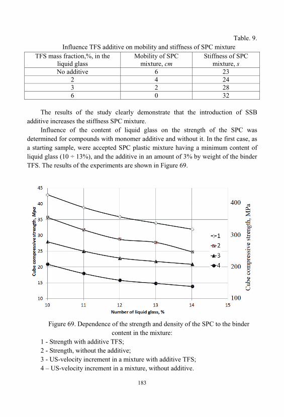
183
Table. 9. Influence TFS additive on mobility and stiffness of SPC mixture
TFS mass fraction,%, in theliquid glass
Mobility of SPCmixture, cm
Stiffness of SPCmixture, s
No additive 6 232 4 243 2 286 0 32
The results of the study clearly demonstrate that the introduction of SSBadditive increases the stiffness SPC mixture.
Influence of the content of liquid glass on the strength of the SPC wasdetermined for compounds with monomer additive and without it. In the first case, asa starting sample, were accepted SPC plastic mixture having a minimum content ofliquid glass (10 ÷ 13%), and the additive in an amount of 3% by weight of the binderTFS. The results of the experiments are shown in Figure 69.
Figure 69. Dependence of the strength and density of the SPC to the bindercontent in the mixture:
1 - Strength with additive TFS; 2 - Strength, without the additive; 3 - US-velocity increment in a mixture with additive TFS; 4 – US-velocity increment in a mixture, without additive.
184
Experiments have shown that the strength and density of the samples SPCincreases with decreasing content of liquid glass in the whole range of change. Reducing the amount of binder only 3% leads to an increase in strength SPCapproximately 25%. It can be assumed that this phenomenon is associated with thefilm thickness of cementations binder, which envelops grain filler as with decreasingthickness increase its adhesive properties, thereby helping to increase the strength anddensity of the mixture.
It should be noted that the introduction of the SPC 0.3% additive TPS increasesthe strength and density of the material by approximately 50% over the entire rangestudied content of liquid glass [173,238].
SPC plastic mixture allows to make any design of geometric shapes in crampedconditions concrete placement, therefore, further optimization procedure of SPC wascarried out while maintaining the content of liquid glass in an amount of 11 ÷ 11.5, and 3% by weight of the binder, monomer additives: furfuryl alcohol (FS) or TFS.
Optimization variables were:
1 - the weight ratio of the binder: filler;
2 - the percentage of sand in the mixture of fillers;
3 - percentage of liquid glass in a mixture of SPC. Optimization objective functions were compressive strength SPC aged 28 days,
st and mixtures stiffness, hr while limiting hr 30 s.
The result of the optimization process was the regression equations:
st = 37,6 – 5,7 1 – 1,5 2 + 17 1 3;
hr = 23 – 4,5 1 – 15 3 + 7,4 x12 + 4,4 x2
2, They allow you to get the optimum composition of the SPC mixture (Table 10).
Table. 10. Optimum composition SPC
ComponentsComposition number
1 2 3Mass fraction, %
Liquid glass (1,4 g/cm3) 11.23 11.23 11.23Na2SiF6 (2700 cm2/g) 1.68 1.68 1.68
Diabase powder (2400 2/ ) 20.06 20.06 20.06Quartz sand 26.71 26.71 26.71
Granite rubble (5÷10 ) 40.32 30.98 30.98FA - 0.34 -TFS - - 0.34
TOTAL 100 100 100
185
Physical and mechanical properties of the optimal composition of the SPC areshown in Table. 11.
Table 11. Physical and mechanical characteristics of the optimal composition of the SPC
ParameterUnits of
measurementNumber optimal composition
1 2 3Cube compressivestrength
MPa
20÷25 28 36÷41
Prism compressivestrength
- 20÷22 30÷35
Tensile strength 1.5 3.2 4.1Tensile strength inbending
- 6 10
Elastic modulus (1.6÷1.7)·104 (1.9÷2.1)·104 (2.4÷2.6)·104
Poisson's ratio - - 0.23 0.21Longitudinaldeformation
mm/m-
(140÷150)·10-
5(150÷165)·10-
5
Lateraldeformation
- (30÷40)·10-5 (55÷60)·10-5
Impact elasticity kJ/m2 - 2.3 5.5Thermal expansioncoefficient
1/ - 8·10-6 8.7·10-6
Shrinkagedeformation after28 days
% 0.39 0.22 0.06
It should be noted that the compressive strength and deformability of samples ofthe mixture SPC modified additive TFS were maximized.
The study showed that the introduction of monomer additives leads to a drasticreduction of shrinkage strain. Shrinkable deformations SPC 28 days old amounted toonly 0.06% at a content in a mixture of 3% TFS.
The trend in the shrinkage strain SPC samples containing additive TFS andwithout it, the time is shown in Figure 70. Samples of the SPC mixture withoutadditives are characterized by exponential growth shrinkage deformations during thesetting of the concrete. Education of the concrete structure is accompanied by intensecompression of the gel by capillary forces intermicellar liquid. To the monomermixture without additives, such liquid is water. Compression of the gel results in a
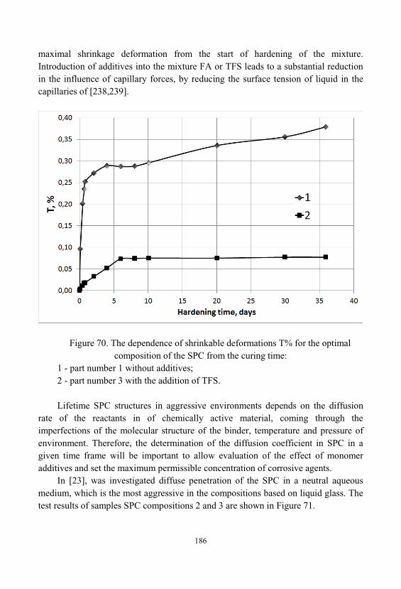
186
maximal shrinkage deformation from the start of hardening of the mixture. Introduction of additives into the mixture FA or TFS leads to a substantial reductionin the influence of capillary forces, by reducing the surface tension of liquid in thecapillaries of [238,239].
Figure 70. The dependence of shrinkable deformations T% for the optimalcomposition of the SPC from the curing time:
1 - part number 1 without additives; 2 - part number 3 with the addition of TFS.
Lifetime SPC structures in aggressive environments depends on the diffusionrate of the reactants in of chemically active material, coming through theimperfections of the molecular structure of the binder, temperature and pressure ofenvironment. Therefore, the determination of the diffusion coefficient in SPC in agiven time frame will be important to allow evaluation of the effect of monomeradditives and set the maximum permissible concentration of corrosive agents.
In [23], was investigated diffuse penetration of the SPC in a neutral aqueousmedium, which is the most aggressive in the compositions based on liquid glass. Thetest results of samples SPC compositions 2 and 3 are shown in Figure 71.
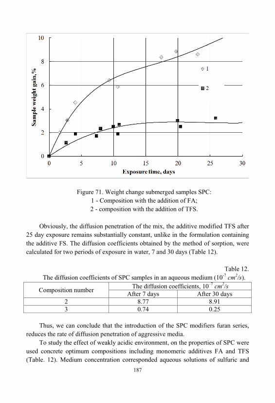
187
Figure 71. Weight change submerged samples SPC:1 - Composition with the addition of FA;2 - composition with the addition of TFS.
Obviously, the diffusion penetration of the mix, the additive modified TFS after25 day exposure remains substantially constant, unlike in the formulation containingthe additive FS. The diffusion coefficients obtained by the method of sorption, werecalculated for two periods of exposure in water, 7 and 30 days (Table 12).
Table 12. The diffusion coefficients of SPC samples in an aqueous medium (10-7 cm2/s).
Composition numberThe diffusion coefficients, 10–7 cm2/s
After 7 days After 30 days2 8.77 8.913 0.74 0.25
Thus, we can conclude that the introduction of the SPC modifiers furan series, reduces the rate of diffusion penetration of aggressive media.
To study the effect of weakly acidic environment, on the properties of SPC wereused concrete optimum compositions including monomeric additives FA and TFS(Table. 12). Medium concentration corresponded aqueous solutions of sulfuric and
188
hydrochloric acids used for etching metals. Corrosion resistance of the SPC assessedby change of the compressive strength of concrete samples after 3 ÷ 18 monthsexposure in environments with an interval of 3 months.
Effect of the monomer type additives the strength of SP after 18-monthexposure concrete samples in a weakly acidic aqueous medium are shown in Table. 13.
Table. 13. Compressive strength of samples SPC (MPa) after exposure to the corrosive
environment
Type of additivesAggressive environment
- 2 % H2SO4 2 % HClTFS 33.8 36.3 34.6FA 25.3 25.0 24.8
This show that a small change in the content of liquid glass, dramaticallychanges technological characteristics of SP . With the decrease in the amount ofliquid glass, increase the strength and density of the SPC; optimum composition ofSPC includes 11.23% liquid glass and 0.34% monomeric additives (FS or TFS); SPCcomposition modified with TFS additive has high compressive strength and highdeformability; the introduction of the SPC monomeric additives TFS increases thestiffness mixture, and very substantial, decrease of shrinkable deformations; additivesof furan series, reduce the diffusion penetration of aggressive environment in SPCstructure and improve its corrosion resistance.
7.4. Deposition of Protective Coatings on the Surface
In existing technical solution is regarding QAS-based compositions, the coatingsare prepared by sedimentation from binary (aqueous) or tertiary (water + QAS +organic compounds) solutions onto the treated surface (metal, concrete, ceramics andwood) and drying at temperatures up to 150÷200°C [240,241]. However, the furthertreatment of the fresh coating depends on the properties needed [242].
FIRE PREVENTION. QAS-based compositions can be effectively used for thefire prevention, for example, impregnation of paper. The mechanical tests of theimpregnated paper were accomplished by tension loading and gave the result 0.023kg/mm2; breaking took place on the paper (the tests were accomplished inPOLYMATE Ltd., Migdal Emek, Israel). Fire retarding found from fire tests was 5min.
189
Depending on the regime of the impregnation, the mechanical properties of theimpregnated paper may vary in a wide spectrum.
It is widely known that most of organic coatings, particularly epoxy-basedcoatings are excellent and cheap but extremely flammable. Using of QAS- basedcompositions allows solution of this problem.
Tests accomplished in AMSIL Ltd. (Migdal Emek, Israel) showed that thecombination of organic adhesive (e.g., epoxy resin) with QAS reduced theflammability, whereas the organic adhesive determines the adhesive properties of themixture. As result, the flammability of the adhesive composition is neutralized, without significant change in adhesive properties.
In the case of the preparation of corrosion / bio / fire-resistant coating, theprimary composition containing a tertiary solution "water - QAS - organiccompound", after being dried, is heated on purpose to remove the rest of water. Theprocess of water removal is accompanied by the formation of very narrow pores(micropores). The obtained solid structure is microporous, characterized by a verylow permeability. Such coatings resist to an oxidation and (due to the silicate base)also UV. With time, the protective properties are not lost but seriously improved, dueto a self-stabilization of the silicate structure. This factor makes QAS-based coatingsvery effective in the protection of buildings and historical and cultural objects fromcarbon / sulfur / nitrogen oxides, humidity, UV and other destructive factors fromenvironment.
INDUSTRIAL PROTECTIVE COATINGS. QAS-based coatings have a verygood adhesion hydrophilic and most of hydrophobic surfaces, due to surfactantproperties of QAS. For testing the proposed adhesive composition, the glued samplesof aluminum-aluminum, iron-iron, concrete-concrete and wood-wood were prepared. The adhesive properties were tested on the breaking tension-loading machine. Theinflammation and self-extinguishing properties have been studied with the directcontact of coated samples with fire of burner, in identical conditions of inflammation[181,182].
As follows from the data, the optimal combination of fire resistance to themechanical stability is obtained for n=7÷10.
In the light of the danger of bacteriological terrorism, QAS-based coatingsprepared at low or moderate temperatures (up to 200°C) get an additional advantageas biologically-safe coverage.
CONDUCTIVE COATINGS. A different situation is observed in the case ofconductive QAS-based coatings prepared by sedimentation onto ceramic or metalsurface from aqueous suspensions containing QAS and conductive components(preferably amphoteric metal powders), drying under temperature up to 200°C forremoval of water and volatile organic components and then heating to high
190
temperatures (650-700°C), stimulating the reaction between the fresh silicate with therest of alkali groups and the conductive component, that leads to the formation of avery compact coating. Depending on the preparation conditions, the coating can bestable under high temperatures (1100°C for 40 min.), while its conductivity can behigh (comparable to metals), moderate or very low.
An assembly includes an integrated circuit die coupled to another component ofthe assembly with an alkali silicate glass material. The alkali silicate material mayinclude particles for modifying the thermal, mechanical, and/or electricalcharacteristics of the material [287].
Low-conductivity modification is fire / temperature resistant. It is also resistantagainst water (pure and saline), oxidation and UV and can be used as a protectivecoating applied at high temperature. For QAS-based coating containing Al-powder, treated up to 400°C and exposed (twice) in water for 24 hs. with further drying, theloss of weight was less 1%. In saline water (NaCl up to 300 g/l) there was found inchange of the adhesive characteristics either color or other visible characteristics ofthe coating during 3 months. The conductive modification is also very resistive andcan be used in heating elements. Such heating elements are not sensitive to eventualdrops, which make them effective for needs of domestic exploitation, good for dryingdevices in textile industry, various furnaces etc.
Multiple heating / cooling cyc.es do not significantly change the electricalcharacteristics of this kind of coatings (thermal hysteresis is negligible), that allowsconclusion their high resistance to oxidation under high temperatures.
Conductive temperature-resistant coatings can get various applications, including military technique, electronic industry, space applications, measuringequipment operating at high temperatures, e.g. measuring data of volcanic lava, heating equipment, fire sources, etc. Conductive compositions are commonly used forcoating of various flat and curved substrates, e.g. heating elements, integrated circuitboards used for electronic components etc.
As conductive components in the conductive coating, one may use knowncommercially available inorganic metallic or non-metallic fillers, e.g. nickel, cobalt, iron, graphite, etc. Viscosity by Ford Viscosity Cup: 40-92 s. (depends on the contentof the filler). Scratching adhesion: on sled - good, aluminum, ceramics – satisfactory.
The thickness of the layer is up to 1.5 mm; the coating is applied to a surface bybrushing spray or analogous technique. The composition car is kept without changesfor 3 years and larger as a binary system (Liquid + Solid) closed (Table 14.).
Advanced waterborne environmentally friendly and weather resistant fire-protective coating composition was elaborated. The composition consists from acombination of intumenscent organic and inorganic particles, an inorganic water
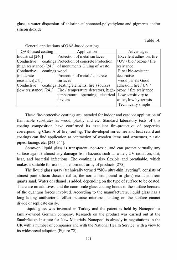
191
glass, a water dispersion of chlorine-sulphonated-polyethylene and pigments and/orsilicon dioxide.
Table 14. General applications of QAS-based coatings
QAS-based coating Application AdvantagesIndustrial [240]Conductive coatings(high resistance) [241]Conductive coatings(moderateresistance[241]Conductive coatings(low resistance) [241]
Protection of metal surfacesProtection of concrete Protectionof monuments Gluing of wastewoodProtection of metal / concretesurfacesHeating elements, fire ) sourcesFire / temperature detectors, high-temperature operating electricaldevices
Excellent adhesion, fire/ UV / bio / ozone / fireresistanceFire / bio-resistant
decorativewood panels Good
adhesion, fire / UV /ozone / fire resistanceLow sensitivity to
water, low hysteresisTechnically simple
These fire-protective coatings are intended for indoor and outdoor application offlammable substrates as wood, plastic and etc. Standard laboratory tests of thiscoating composition have confirmed its excellent fire-protective of propertiescorresponding Class A of fireproofing. The developed series fire and beat retard antcoatings can find application at contraction of wooden items and structures, plasticpipes, facings etc. [243,244].
Spray-on liquid glass is transparent, non-toxic, and can protect virtually anysurface against almost any damage from hazards such as water, UV radiation, dirt, heat, and bacterial infections. The coating is also flexible and breathable, whichmakes it suitable for use on an enormous array of products [275].
The liquid glass spray (technically termed “SiO2 ultra-thin layering”) consists ofalmost pure silicon dioxide (silica, the normal compound in glass) extracted fromquartz sand. Water or ethanol is added, depending on the type of surface to be coated. There are no additives, and the nano-scale glass coating bonds to the surface becauseof the quantum forces involved. According to the manufacturers, liquid glass has along-lasting antibacterial effect because microbes landing on the surface cannotdivide or replicate easily.
Liquid glass was invented in Turkey and the patent is held by Nanopool, afamily-owned German company. Research on the product was carried out at theSaarbrücken Institute for New Materials. Nanopool is already in negotiations in theUK with a number of companies and with the National Health Service, with a view toits widespread adoption (Figure 72).
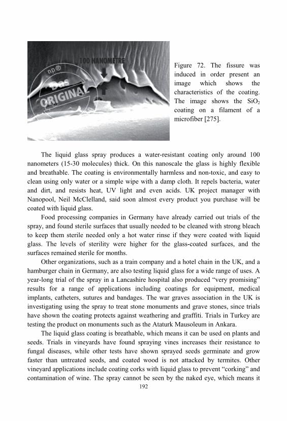
192
Figure 72. The fissure wasinduced in order present animage which shows thecharacteristics of the coating. The image shows the SiO2
coating on a filament of amicrofiber [275].
The liquid glass spray produces a water-resistant coating only around 100nanometers (15-30 molecules) thick. On this nanoscale the glass is highly flexibleand breathable. The coating is environmentally harmless and non-toxic, and easy toclean using only water or a simple wipe with a damp cloth. It repels bacteria, waterand dirt, and resists heat, UV light and even acids. UK project manager withNanopool, Neil McClelland, said soon almost every product you purchase will becoated with liquid glass.
Food processing companies in Germany have already carried out trials of thespray, and found sterile surfaces that usually needed to be cleaned with strong bleachto keep them sterile needed only a hot water rinse if they were coated with liquidglass. The levels of sterility were higher for the glass-coated surfaces, and thesurfaces remained sterile for months.
Other organizations, such as a train company and a hotel chain in the UK, and ahamburger chain in Germany, are also testing liquid glass for a wide range of uses. Ayear-long trial of the spray in a Lancashire hospital also produced “very promising”results for a range of applications including coatings for equipment, medicalimplants, catheters, sutures and bandages. The war graves association in the UK isinvestigating using the spray to treat stone monuments and grave stones, since trialshave shown the coating protects against weathering and graffiti. Trials in Turkey aretesting the product on monuments such as the Ataturk Mausoleum in Ankara.
The liquid glass coating is breathable, which means it can be used on plants andseeds. Trials in vineyards have found spraying vines increases their resistance tofungal diseases, while other tests have shown sprayed seeds germinate and growfaster than untreated seeds, and coated wood is not attacked by termites. Othervineyard applications include coating corks with liquid glass to prevent “corking” andcontamination of wine. The spray cannot be seen by the naked eye, which means it
193
could also be used to treat clothing and other materials to make them stain-resistant. McClelland said you can “pour a bottle of wine over an expensive silk shirt and itwill come right off”.
In the home, spray-on glass would eliminate the need for scrubbing and makemost cleaning products obsolete. Since it is available in both water-based andalcohol-based solutions, it can be used in the oven, in bathrooms, tiles, sinks, andalmost every other surface in the home and one spray is said to last a year.
Liquid glass spray is perhaps the most important nanotechnology product toemerge to date. It will be available in DIY stores in Britain soon, with prices startingat around £5 ($8 US). Other outlets, such as many supermarkets, may be unwilling tostock the products because they make enormous profits from cleaning products thatneed to be replaced regularly, and liquid glass would make virtually all of themobsolete.
7.5. Silicate Nanomiaterials Coatings for Protection ofMonuments of History, Architecture and cultural heritage
Nanotechnology is considered as a new technological revolution, one soprofound that will touch all the aspects of human society. Research groups believethat nanotechnologies could be successfully applied for the conservation of culturalheritage which is the base of our history and culture. In the past 20 years manyresearches have focused on developing suitable materials for consolidating andprotecting materials as well as structures success, but the result of most of thesemethods is the increasing of decay or the rejection of the intervention.
A very perspective field of the use of QAS-based coatings is the protection ofhistorical and cultural ancient monuments and buildings from damaging componentsin the air and rains - SO2, NO2, CO2 [16,130].
Experiments realized in AMSIL Ltd. show that QAS-based coating prevents theacid corrosion of calcium / magnesium-based material ("Jerusalem stone"), fromwhich most known monuments are built. "Jerusalem stone" samples were coated withAMSIL and treated by various acid solutions during 24 h, the results were comparedwith the control (non-coated) sample. As follows from Table 15, QAS-based coatingssignificantly reduce the rate of acid corrosion of carbonate-based mate
194
Table 15. Influence of QAS-based coatings on the rate of acid corrosion of "Jerusalem
Stone"Corrosive solution Coated sample Non-coated sampleAcetic acid, pH 3 No changes in weight, sight 4.5% weight loss
Sulfuric acid, 30 wt. % 2% weight loss 8.6% wt. loss
In [276] the Author was focused on the problems in conservation of ancientmaterials, identifying some possibilities in the applications of nanotechnologies in thefield of conservation of architectural cultural heritage. Nanoparticles have dimensionsthat are less than 100 nm. As a result of their very small size, they possess differentproperties to their corresponding bulk material. Their small dimensions areresponsible for their large surface area, and this in turn results in a considerablyincreased surface to volume ratio, which then affects the nanoparticles physico-chemical properties. In particular they have distinctive optical, electronic, electrical, magnetic, chemical and mechanical properties.
The aim of this contribution is to evaluate the effectiveness of inorganiccompatible treatments, based on nanosized particles of silicon dioxide as consolidantsfor ancient stones and wooden surfaces affected by different kinds of decay. Both insitu and laboratory tests were carried out and the re-aggregating effects of thedeposited phase were investigated by superficial area analyses (BET) and SEM-EDX;it was also possible to obtain an estimation of the depth of penetration of the productinside the porous matrix. All the results converged in individuating these nanometricparticles as an innovative, completely compatible, and efficient material for theconsolidation of ancient and architectural surfaces.
The new patent, invented in 2011 and entitled Innovative sonochemical processthat employs ultrasonic cavitation for the synthesis of mono-dispersed amorphoussilicon dioxide nanoparticles, and a method for producing high-performance water-soluble lithium silicate compounds, for the application in the consolidation in situ ofancient stone and wood structures [277], represents a powerful breakthrough in thesynthesis of new materials for the protection of buildings, therefore for theimprovement of the built environment. This invention relates to a process forsynthesizing amorphous nanoparticles and mono-dispersed of silicon dioxide (SiO2), and a method for preparing a compound water-soluble inorganic compound oflithium silicate by reaction, in water, of lithium hydroxide and/or carbonate with saidnanoparticles and mono-dispersed of silicon dioxide.
Process and method are in place through the use of ultrasonic energy with afrequency between 10 kHz and 100 kHz. That compound of high-performancelithium silicate is applied in situ for the consolidation of ancient stone and wooden
195
structures. In particular, the innovation of the present invention is that of creatingeconomically and conveniently nanoparticles of silicon dioxide, through a newprocess of synthesis which employs ultrasonic cavitation, totally unknown in the stateof the art of science and technology. Ultrasonic cavitation is the energetic effectwhich is basically used by ultrasound.
To be more precise, the ultrasonic cavitation is a physical phenomenonconsisting in the creation of vacuum “tears” commonly referred to as “bubbles” in afluid which immediately and violently implode. This compound of silicon dioxide innanoscale structure can subsequently react with lithium hydroxide and/or carbonate, in water, to form a specific inorganic material of high-performance having newcharacteristics. The nanoparticles of silicon dioxide have a crucial role in the creationof a new form of water-soluble lithium silicate, to be applied in situ improving theperformance of stone and wood materials of ancient structures, essential for a lot ofapplications in numerous fields of technology. This new material of lithium silicateperforms the task perfectly respecting the environment, without changing thephysico-chemical and mechanical structures of the treated materials, and all with nolasting effects. This new process belongs to a field of nanoscience and is directed tothe creation and utilization of materials, with dimensions at the molecular level, withfeatures not only greatly improved compared to the traditional ones, but evencompletely innovative.
In fact, the properties and behavior of nanoscale material, obtained according tothe teachings of the present invention, provides an opportunity to create inorganiccompounds of lithium silicate that operate in a completely different way than thosewith macro dimensions. In the following example, it is described an economicalmethod for synthesizing nanoparticles of silicon dioxide, through the use ofultrasonic cavitation and use of sodium silicate as a precursor. Further characteristicsand advantages of the object of the present invention will become more apparentthrough the example of a preferred embodiment, but not exclusive, of the invention, described by way of non-limitative example of the nature of the invention.
In order to what has been described in detail, the experts in the field canunderstand that variations in the way of realization of the invention described in theexample here shown are possible without thereby alter the technical concepts and/orthe essential characteristics of the invention.
Therefore, it must be expressly understood that the above example has beenproposed only for illustrative and not limitative model of the present invention.
Finally, the invention includes all modifications; additions and substitutionsderived from the purpose and spirit of the invention are well declared in the includedfollowing claims:
196
1) Sonochemical process that uses ultrasonic cavitation for the synthesis of silica(SiO2) in the form of amorphous mono-dispersed nanoparticles, characterized in thatsaid silicon dioxide is prepared by use of hydrochloric acid (HCl) and sodium silicateas a precursor.
2) Process as claimed in Claim 1, characterized in that the hydrochloric acidconcentration should be from 0.1% to 5.0 %.
3) Process as claimed in Claims 1 to 2, characterized in that it uses ultrasonicenergy at a frequency between 10 KHz to 100 KHz, and more particularly between20KHz and 40 KHz.
4) Process as claimed in Claims 1 to 3, characterized in that the size of silicananoparticles can be controlled by varying the frequency of the ultrasonic energy.
5) Process as claimed in Claims 1 to 4, characterized in that the mono-dispersedsilica nanoparticles have sizes ranging from 1 nm to 100 nm and more particularlyfrom 10 nm to 50 nm.
6) Process as claimed in Claims 1 to 5, characterized in that these silicananoparticles can react with lithium hydroxide and/or carbonate in aqueous solutionto obtain water-soluble lithium silicate with nanoscale structure.
7) Process as claimed in Claim 6, characterized in that said water-solublelithium silicate can be applied in situ for the consolidation and protection of stone andwooden of ancient structures.
8) Method for preparing a water-soluble inorganic compound of lithium silicateby use of ultrasonic energy having a frequency between 10 kHz and 100 kHz, characterized in that said lithium silicate compound is obtained by reaction, in water, of lithium hydroxide and/or carbonate with silica nanoparticles synthesized accordingto the above Claims 1 to 5.
9) Method as claimed in Claim 8, characterized in that for the preparation ofsaid water-soluble lithium silicate can be used ultrasonic energy having a frequencybetween 20 KHz and 60 KHz.
10) Method as claimed in Claim 9, characterized in that said water-solublelithium silicate can be present in aqueous solution with a maximum solids content of40 wt.% and a max viscosity of 20 mPas.
11) Method as claimed in Claims 8 to 10, characterized in that the consolidationof natural stones, historic plasters and wooden structures, is produced in situ using anaqueous solution of lithium silicate, whose maximum concentration is less than 20wt.% and is characterized by a Li2O:SiO2 ratio of 1.0: 1.0 ÷ 20.0.
12) Method as claimed in Claims 8 to 11, characterized in that the aqueoussolution consisting of lithium silicate has maximum concentration less than 10 wt%.
The consolidating power of water-soluble lithium silicate is highly dependent onthe size of the amorphous and mono-dispersed nanoparticles of silicon dioxide. The
197
sonochemical technique, which uses ultrasonic cavitation, has the followingadvantages in the synthesis of nanoparticles of silicon dioxide: versatility and ease ofexecution, purity, consistency and high performance of the material obtained. In fact, the self-cleaning ability of this new type of silicon dioxide, having a nanoscalestructure, applied directly to the stone and wooden surfaces, allows us to preservetheir condition unchanged, without any alterations to their appearance of technicalfeatures, preventing biological pollutants and corrosion impurities, effectivelycounteracting the deterioration of the surfaces of stone materials [278].
This invention, with numerous studies in the field, demonstrate a commitmentand interest in the research for innovative materials and the most reliable systems toensure the consolidation and restoration of ancient structures, significantly reducingmaintenance costs. Several lines of research have developed innovative methods andnew production processes that allow nanostructured materials to become anadvantageous and indispensable component for the preservation, enhancement andappreciation of the ancient built environment. These new nanomaterials can besuccessfully tested and verified to help bringing history to life, to protect our builtenvironment, setting the stage for a really accessible and safeguarded city in thefuture.
7.6. Application of Sols to Obtain Inorganic Composites andCeramics
Application of sols to obtain inorganic composites widely covered in theliterature. Previously, it was described the use of a binder as silicic acid sols with theSiO2 concentration of from 3 to 12% and a particle size of from 4 to 10 nm [245]. There is also shown data for shrinkage in relation to temperature. Thus, withincreasing temperature from 1000 to 1400 shrinkage increases from 1.22 to 3.4%.
To increase the tensile strength during the manufacture of the refractory heatinsulating material, it is proposed to use components in the following order:aluminosilicates fiber - 75 ÷ 95% silicic acid sols is 5÷15% [246]. In [247] the usesof alumina gel for bonding the ceramic fibers in the preparation of the liquid mass. The review [37] examined the technological problems encountered in obtainingmonolithic glass by sol-gel method. The main technological problem is to preservethe integrity of the material (to prevent cracking), when implementing of transitions:sol - hydrogel - xerogel - glass [248].
In [251,252] analysis was made of specific features produce ultrafine powdersby sol-gel technology using both soluble silicates and sols.
198
Authors [246] developed the production technology of heat-resistant tiles on thebasis of silicic acid sols. Prepared plate size 1000 × 500 mm, density 200-230 kg/m3, compressive strength at 10% deformation 0.08-0.1 MPa.
Thus, the use of sols as binders to obtain ceramics requires, above all, resolvethe following issues. Selection of method for producing of binder materials, the studyof their properties (dispersity, pH, concentration, gelation time) and studying ofinfluence their properties on the structural characteristics of the gels formed fromthem.
Precipitation. This method - one of the most common methods of producingporous materials accompanied usually transitions sol-gel xerogel. Each of thesetransitions, the sol-gel, gel-xerogel, regardless of its mechanism of action, contributesto the overall process of pore formation. These passages, as shown in [253], are verysensitive to external influences: pH, nature intermicellar fluid and the presence ofsurfactants. These factors greatly affect the aggregation of particles to form or loose, fishnet of spatial patterns or dense structures. Therefore purposefully influencing thepassage of these processes, adjusting their depth and direction can be controlledstructure formation, synthesizing materials with predetermined porosity andmechanical strength.
Deposition method was studied in detail to obtain adsorbents, catalysts, inorganic ion exchangers. To obtain them, are most often used, the solutions of saltsof mineral and carboxylic acids. The deposition may be carried out with aqueoussolutions of ammonia or alkali carbonates, in the cold or by heating in concentratedor diluted solutions. The concentration, temperature and deposition rate can bechanged in a wide range established empirically. Freshly precipitated hydroxides aregenerally amorphous (gels SiO2, MnO2, ZrO2, Nd2O5, Ta2O5), and only some of them(gels Al2O3, MgO, TiO2) crystallize with time, becoming a faceted particles [254]. Gel aging leads to a redistribution of matter, whereby the particles closer together, and in some cases become larger, and their contacts grow together. This leads to astrengthening of the skeleton of the gel, reducing its dispersity, and thus to reduce theshrinkage during drying. According to the type and shape of particles comprising thegel and the xerogel, can be subdivided into globular (silica gel and alumina gel), rod-like (gel tungsten oxide), spindly (barium sulfate), rod-like and filamentous (an oxideof vanadium (V)), etc. Mixed materials are often used, which in most cases exhibit asynergistic effect [193].
Thermal decomposition. This method is used to obtain porous oxide materialsby thermal decomposition of a variety of compounds: hydroxides, carbonates, oxalates, hydrides, etc. The resulting products - highly dispersed substance with awell-developed system of capillaries, sometimes quite definite size and shape. Sometimes there are cases topotaxial mechanism processes of decomposition when
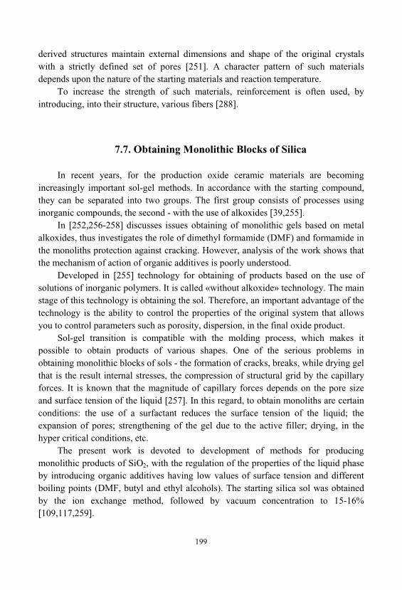
199
derived structures maintain external dimensions and shape of the original crystalswith a strictly defined set of pores [251]. A character pattern of such materialsdepends upon the nature of the starting materials and reaction temperature.
To increase the strength of such materials, reinforcement is often used, byintroducing, into their structure, various fibers [288].
7.7. Obtaining Monolithic Blocks of Silica
In recent years, for the production oxide ceramic materials are becomingincreasingly important sol-gel methods. In accordance with the starting compound, they can be separated into two groups. The first group consists of processes usinginorganic compounds, the second - with the use of alkoxides [39,255].
In [252,256-258] discusses issues obtaining of monolithic gels based on metalalkoxides, thus investigates the role of dimethyl formamide (DMF) and formamide inthe monoliths protection against cracking. However, analysis of the work shows thatthe mechanism of action of organic additives is poorly understood.
Developed in [255] technology for obtaining of products based on the use ofsolutions of inorganic polymers. It is called «without alkoxide» technology. The mainstage of this technology is obtaining the sol. Therefore, an important advantage of thetechnology is the ability to control the properties of the original system that allowsyou to control parameters such as porosity, dispersion, in the final oxide product.
Sol-gel transition is compatible with the molding process, which makes itpossible to obtain products of various shapes. One of the serious problems inobtaining monolithic blocks of sols - the formation of cracks, breaks, while drying gelthat is the result internal stresses, the compression of structural grid by the capillaryforces. It is known that the magnitude of capillary forces depends on the pore sizeand surface tension of the liquid [257]. In this regard, to obtain monoliths are certainconditions: the use of a surfactant reduces the surface tension of the liquid; theexpansion of pores; strengthening of the gel due to the active filler; drying, in thehyper critical conditions, etc.
The present work is devoted to development of methods for producingmonolithic products of SiO2, with the regulation of the properties of the liquid phaseby introducing organic additives having low values of surface tension and differentboiling points (DMF, butyl and ethyl alcohols). The starting silica sol was obtainedby the ion exchange method, followed by vacuum concentration to 15-16%[109,117,259].
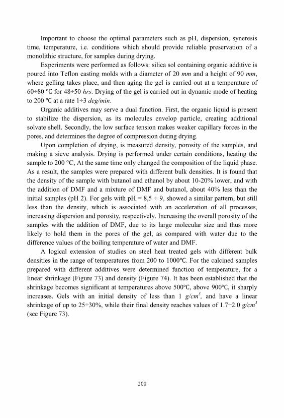
200
Important to choose the optimal parameters such as pH, dispersion, syneresistime, temperature, i.e. conditions which should provide reliable preservation of amonolithic structure, for samples during drying.
Experiments were performed as follows: silica sol containing organic additive ispoured into Teflon casting molds with a diameter of 20 mm and a height of 90 mm, where gelling takes place, and then aging the gel is carried out at a temperature of60÷80 for 48÷50 hrs. Drying of the gel is carried out in dynamic mode of heatingto 200 at a rate 1÷3 deg/min.
Organic additives may serve a dual function. First, the organic liquid is presentto stabilize the dispersion, as its molecules envelop particle, creating additionalsolvate shell. Secondly, the low surface tension makes weaker capillary forces in thepores, and determines the degree of compression during drying.
Upon completion of drying, is measured density, porosity of the samples, andmaking a sieve analysis. Drying is performed under certain conditions, heating thesample to 200 °C, At the same time only changed the composition of the liquid phase. As a result, the samples were prepared with different bulk densities. It is found thatthe density of the sample with butanol and ethanol by about 10-20% lower, and withthe addition of DMF and a mixture of DMF and butanol, about 40% less than theinitial samples (pH 2). For gels with pH = 8,5 ÷ 9, showed a similar pattern, but stillless than the density, which is associated with an acceleration of all processes, increasing dispersion and porosity, respectively. Increasing the overall porosity of thesamples with the addition of DMF, due to its large molecular size and thus morelikely to hold them in the pores of the gel, as compared with water due to thedifference values of the boiling temperature of water and DMF.
A logical extension of studies on steel heat treated gels with different bulkdensities in the range of temperatures from 200 to 1000 . For the calcined samplesprepared with different additives were determined function of temperature, for alinear shrinkage (Figure 73) and density (Figure 74). It has been established that theshrinkage becomes significant at temperatures above 500 , above 900 , it sharplyincreases. Gels with an initial density of less than 1 g/cm3, and have a linearshrinkage of up to 25÷30%, while their final density reaches values of 1.7÷2.0 g/cm3
(see Figure 73).
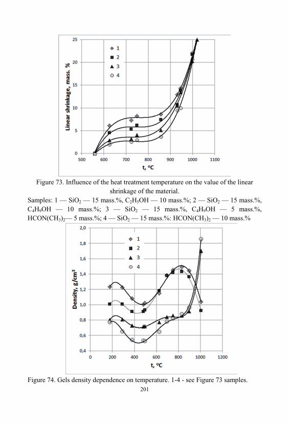
201
Figure 73. Influence of the heat treatment temperature on the value of the linearshrinkage of the material.
Samples: 1 — SiO2 — 15 mass.%, 2 5 — 10 mass.%; 2 — SiO2 — 15 mass.%,
4 9 — 10 mass.%; 3 — SiO2 — 15 mass.%, 4 9 — 5 mass.%, N( 3)2— 5 mass.%; 4 — SiO2 — 15 mass.%: H N( 3)2 — 10 mass.%
Figure 74. Gels density dependence on temperature. 1-4 - see Figure 73 samples.
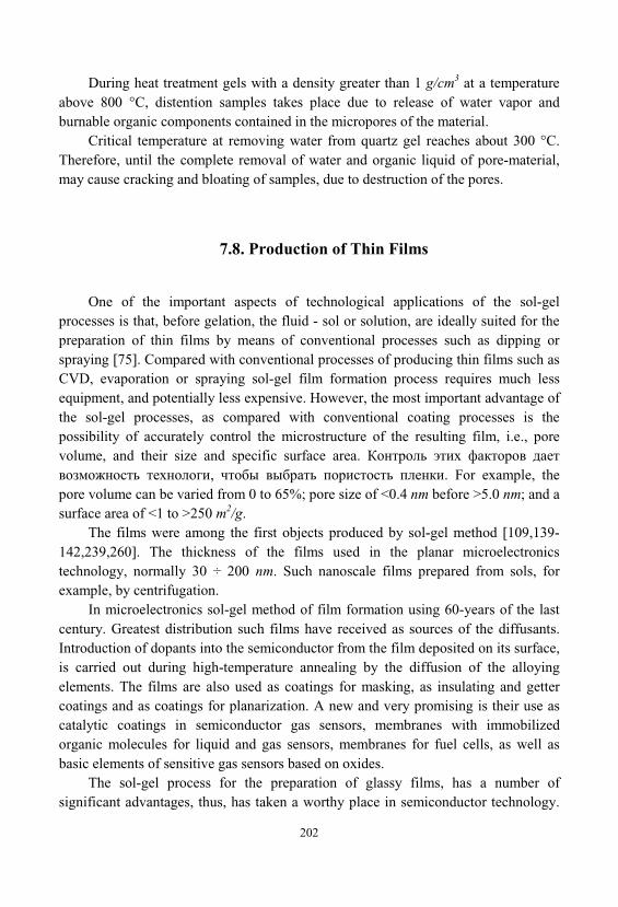
202
During heat treatment gels with a density greater than 1 g/cm3 at a temperatureabove 800 °C, distention samples takes place due to release of water vapor andburnable organic components contained in the micropores of the material.
Critical temperature at removing water from quartz gel reaches about 300 °C. Therefore, until the complete removal of water and organic liquid of pore-material, may cause cracking and bloating of samples, due to destruction of the pores.
7.8. Production of Thin Films
One of the important aspects of technological applications of the sol-gelprocesses is that, before gelation, the fluid - sol or solution, are ideally suited for thepreparation of thin films by means of conventional processes such as dipping orspraying [75]. Compared with conventional processes of producing thin films such asCVD, evaporation or spraying sol-gel film formation process requires much lessequipment, and potentially less expensive. However, the most important advantage ofthe sol-gel processes, as compared with conventional coating processes is thepossibility of accurately control the microstructure of the resulting film, i.e., porevolume, and their size and specific surface area.
, . For example, thepore volume can be varied from 0 to 65%; pore size of <0.4 nm before >5.0 nm; and asurface area of <1 to >250 m2/g.
The films were among the first objects produced by sol-gel method [109,139-142,239,260]. The thickness of the films used in the planar microelectronicstechnology, normally 30 ÷ 200 nm. Such nanoscale films prepared from sols, forexample, by centrifugation.
In microelectronics sol-gel method of film formation using 60-years of the lastcentury. Greatest distribution such films have received as sources of the diffusants. Introduction of dopants into the semiconductor from the film deposited on its surface, is carried out during high-temperature annealing by the diffusion of the alloyingelements. The films are also used as coatings for masking, as insulating and gettercoatings and as coatings for planarization. A new and very promising is their use ascatalytic coatings in semiconductor gas sensors, membranes with immobilizedorganic molecules for liquid and gas sensors, membranes for fuel cells, as well asbasic elements of sensitive gas sensors based on oxides.
The sol-gel process for the preparation of glassy films, has a number ofsignificant advantages, thus, has taken a worthy place in semiconductor technology.
203
Sol-gel technology enables the implementation of many technological processes incontrolled conditions. For example, well-functioning protective, insulating, and otherfilms in electronic devices can be formed at a temperature below 250 ÷ 450 °C. Because the sources of diffusion are, the film with a predetermined, adjustableconcentration of dopant, distortion and defects in the crystal lattice of dopedsemiconductor is minimized [151].
An important advantage of this method of alloying is possible to introduce, atfirst in these films, and then in semiconductor materials, a number of dopants that aredifficult or impossible to introduce by other methods, for example by doping duringgrowth, ion implantation or diffusion from other sources.
The products of partial hydrolysis and pyrolysis, metal alkoxides - polyorgano-metalloxanes, are components of the heat-resistant coatings, and also surfaceactivators, for bonding, it is difficult to be bonded materials.
Solid and fl exible ionogel-based membranes are obtained by a simple onestepprocess. Tuning the composition of the silica–polymer hybrid membranes allows theattainment of highly specifi c properties. The high ionic conductivities of the solidmembranes are in the range of those of the ionic liquid electrolytes on which they arebased. Good mechanical properties and high transparency from 250 to 1000 nm arealso observed. The membranes are successfully applied within entirely solid lithiumbatteries [279].
Encapsulated solid-state dye-sensitized Solar Cells (ssDSSCs) show a reversibleand quick deterioration in performance while aging under inert atmosphere. This isattributed to the activation of deep traps and the change in Schottky barrier at theTiO2 surface. This is remedied by forming an insulating alumino-silicate “shell”around the TiO2 nanocrystals, and by introducing an insulating mesoporous SiO2
“buffer layer” between the top electrode and TiO2 [280].
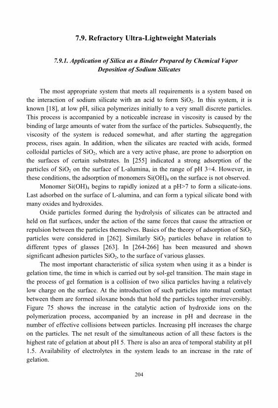
204
7.9. Refractory Ultra-Lightweight Materials
7.9.1. Application of Silica as a Binder Prepared by Chemical VaporDeposition of Sodium Silicates
The most appropriate system that meets all requirements is a system based onthe interaction of sodium silicate with an acid to form SiO2. In this system, it isknown [18], at low pH, silica polymerizes initially to a very small discrete particles. This process is accompanied by a noticeable increase in viscosity is caused by thebinding of large amounts of water from the surface of the particles. Subsequently, theviscosity of the system is reduced somewhat, and after starting the aggregationprocess, rises again. In addition, when the silicates are reacted with acids, formedcolloidal particles of SiO2, which are a very active phase, are prone to adsorption onthe surfaces of certain substrates. In [255] indicated a strong adsorption of theparticles of SiO2 on the surface of L-alumina, in the range of pH 3÷4. However, inthese conditions, the adsorption of monomers Si(OH)4 on the surface is not observed.
Monomer Si(OH)4 begins to rapidly ionized at a pH>7 to form a silicate-ions. Last adsorbed on the surface of L-alumina, and can form a typical silicate bond withmany oxides and hydroxides.
Oxide particles formed during the hydrolysis of silicates can be attracted andheld on flat surfaces, under the action of the same forces that cause the attraction orrepulsion between the particles themselves. Basics of the theory of adsorption of SiO2
particles were considered in [262]. Similarly SiO2 particles behave in relation todifferent types of glasses [263]. In [264-266] has been measured and shownsignificant adhesion particles SiO2, to the surface of various glasses.
The most important characteristic of silica system when using it as a binder isgelation time, the time in which is carried out by sol-gel transition. The main stage inthe process of gel formation is a collision of two silica particles having a relativelylow charge on the surface. At the introduction of such particles into mutual contactbetween them are formed siloxane bonds that hold the particles together irreversibly. Figure 75 shows the increase in the catalytic action of hydroxide ions on thepolymerization process, accompanied by an increase in pH and decrease in thenumber of effective collisions between particles. Increasing pH increases the chargeon the particles. The net result of the simultaneous action of all these factors is thehighest rate of gelation at about pH 5. There is also an area of temporal stability at pH1.5. Availability of electrolytes in the system leads to an increase in the rate ofgelation.
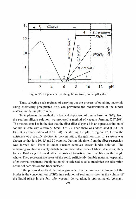
205
Figure 75. Dependence of the gelation time, on the pH value
Thus, selecting such regimes of carrying out the process of obtaining materialsusing chemically precipitated SiO2 can prevented the redistribution of the bindermaterial in the sample volume.
To implement the method of chemical deposition of binder based on SiO2, fromthe sodium silicate solution, we proposed a method of vacuum forming [267,268]. The method consists in the fact that the fiber filler dispersed in an aqueous solution ofsodium silicate with a ratio SiO2/Na2O = 2/3. Then there was added acid (H2SO4 orHCl at a concentration of 0.5÷1 M) for shifting the pH to region <7. Given theexistence of a specific electrolyte concentration, the gelation time in a system waschosen so that it is 10, 15 and 30 minutes. During this time, from the fiber suspensionwas formed felt. From it under vacuum removes excess binder solution. Theremaining solution is evenly distributed in the contact zone of fibers, due to capillaryforces. Bridges gel formed after the sol-gel transition bind the fiber in the singlewhole. They represent the areas of the solid, sufficiently durable material, especiallyafter thermal treatment. Precipitation pH is selected so as to maximize the adsorptionof the sol particles on the fiber surface.
In the proposed method, the main parameter that determines the amount of thebinder is the concentration of SiO2 in a solution of sodium silicate, as the volume ofthe liquid phase in the felt, after vacuum dehydration, is approximately constant.
206
Figure 76 shows the dependence of the density of material formed during thedeposition of SiO2 concentration from sodium silicate binder solution. Presenteddependence is a monotonically increasing and thereby confirms made aboveassumption. Received so lightweight materials represent the sturdy enough fiberblocks.
Figure 76. Dependence of material density on concentration SiO2, in the deposition ofthe binder, from Na2O•mSiO2.
7.9.2. Application of Silica Sol as a Binder
Application of sol as a binder in forming inorganic composites widely coveredin the literature [269]. For example, [270], used as the binder sols of silicic acid witha SiO2 concentration of 3%, 5%, 9%, 12%, and a particle size of 4.7; 6.9; 10.1; 10.9nm.
Change binder concentration from 3 to 6%, resulting in significant changes inthe properties of the material. Thus, the density is increased from 0.49 to 0.58 g/cm3, and the strength is increased from 0.54 to 1.90 MPa. To improve the tensile strengthin the manufacture of refractory heat insulating material, it is proposed to use [147]the components, as follows: aluminosilicates fiber - 75 ÷ 95% silica sol 5 ÷ 25%. Inother works also describe the technologies of production of heat-resistant slabs onsilica sols.
In the studies to obtain heat-insulating refractory materials [272] in thelaboratory used silica sol obtained by the ion exchange method. It had the following
207
characteristics: the concentration of SiO2 - 3%; pH 2 ÷ 8; particle size of 2 ÷ 4 nm. Aluminosilicates fiber has the following composition: Al2O3 - 55 ÷ 49%; SiO2 - 45 ÷99%; SiO2 + Al2O3 not less than 98%. Preparing the samples consists of thefollowing operations [273,274]:
1. Preparation of silica sol;2. Preparation of hydro mass from fibers and silica sol solution in the mixer;3. Formation of products from material;4. Drying, structural fixation;5. Heat treatment and sintering. Preparation of hydro mass comprises: preparation of the fiber homogenization
fibers to remove aggregates and not fibrous inclusions in the sol solution. Preparation of the fiber comprises heat treating it to remove a finish coat from
the surface of the fibers. Complete removal of the finish coat takes place at atemperature of 400 . Finish coat is located on the fiber surface leads to aconsiderable hydrophobization of surfaces, sharp decrease of the adsorption andadhesion interaction of SiO2 particles with a surface of the filler.
After calcination, and removing the finish coat, the fiber filler is placed in water, or a sol solution for homogenization, and removal of aggregates and not fibrousinclusions. Thermally treated fiber is well moistened with water and a solution of thesol. In a mixer with a high-speed stirrer it is within a few minutes is transformed intoa homogeneous suspension. On the character of this process has practically no effectthe disintegration time (in the range from 5 to 30 minutes) and the filler content in theliquid phase (in the range from 4 to 10%) Some influence is the solution temperatureat which homogenization is carried out. The most homogeneous material is obtainedat a temperature of 80÷98 . Such a phenomenon is explained by the fact that at lowtemperatures there is no destruction of the fiber balls into separate fibrils and formedby a structure formed of the fiber balls.
A second step of obtaining lightweight heat-proof materials is forming of blocksfrom the suspension of fibers and binder. At this stage, the pH of the sol is corrected, and it is setting in the range of 5.5÷6.0. The gelation time, most of investigatedsystems are in the range from 20 to 60 minutes. During this time it is necessary toform a block of material, and it is necessary to remove an excess amount of the liquidphase. Block molding process can be implemented in two ways: first - vacuumforming; second - centrifugal casting. Most prevalent in preparation technology, oflightweight fibrous materials have found ways vacuum casting as technologicallymore simple.
To apply the method vacuum casting was developed and producedcorresponding accessories. It was destined for the manufacture of products in theform of tiles measuring 150 × 190 × 19. To equalize the density of the material along
208
the tile thickness, additional compression is applied fibrous felt, with a force of 1 to27 kPa, depending on the desired material density.
Another method acceptable to the block molding lightweight heat-proofmaterials is the method of centrifugal casting. However, this method is rarely used. The advantage of centrifugal casting method is that if the size of the mold muchsmaller than the radius of rotation and at equal mass of all particles, centrifugal forceacts equally on all the particles in the mold. All of the fibers under the action ofcentrifugal forces begin to move uniformly. This allows forming the gradientmaterial, using a suspension with a set of fibers of different masses. Speeds ofmovement of the particles of different masses are different. The most severe particlesmove faster. Thus, the resulting material is formed with a distribution of the particleswith a gradient of mass. Accordingly, in the material occurs the density gradient. Thus, most dense part of the material is located at the greatest distance from thecenter of rotation.
Important technological step is the process of drying the material. At this stage, in the final material, is laid bulk of its strength properties. Character of its passagedepends on, quantity and uniformity of distribution of the binder in the materialstructure. Thus, the presence of large amounts of binder may lead to the, occurrenceof separate sites, which concentrates the binder phase. This results in large internalstresses and cracking of the material during drying and during exploitation ofproducts in the absorption of moisture from the air, and also when a decryptationeffect.
There are several possible ways to enhance the strength characteristics of thefibrous composite materials. The first way - is to increase the content of thecomposite binder. The second way - is the increase in strength, due to additionalsintering. The first way is difficult to implement for several reasons. This, forexample, the technical side is the difficulty of introducing uniform and homogeneouslarge quantity of binder. Therefore, to solve the problem of increasing the materialstrength has been proposed a method of sintering.
Sintering is a process of strengthening and compacting of the starting mixturesdispersed components that are relatively weakly connected to each other. It is due tothe physicochemical transport processes substances which begin and occur, at anappreciable rate at elevated temperatures and in some instances at elevated pressures.
In accordance with the ideas developed in [236,271], a complex series ofprocesses occurring during sintering can be divided into three stages. The first stageoccurs, the mutual sintering of the particles, which is accompanied by an increase intheir contact surface. The total contact surface formed at the same time is still small, and the pores are, cohesive system. In the second stage, the material is converted intoa continuous porous body, where the pore and solid phase are practically cohesive
209
systems. The third stage is characterized by having isolated pores included in thecontinuous solid phase. Sealing material occurs at this stage due to the reduction ofthe number of pores and their size.
For high-strength materials with a density of 0.3÷1.0 g/cm3 is necessary toconduct the sintering, with a stop at the second stage of the process. The maincondition is the formation and growth of contacts between particles. Sinteringlightweight heat-proof refractory materials can only be due to the diffusionmechanism that can wear both surface and volume character.
The driving force of the transfer compound at the diffusion mechanism is thedifference in free energy at the contact point of the particles and on their surfaces, due to the presence of defects. By increasing the number of defects on the particlesurface increases the surface energy. Dislocations and other defects of the internalstructure of the particle, the bulk diffusion increases. However, it is known that glassfibers are an amorphous phase having a very low bulk and surface defects. Aluminosilicate fiber refers to such materials. Thus, among, all the components usedin the preparation of composites, the greatest structure imperfection, have binderphase - gel. Therefore, the maximum sintering rate will be observed in the contactzone of binder and fiberfill. The very same fiber is not very sensitive to the sinteringprocess. The driving force of the sintering process is more pronounced near the smallpores, which leads to overgrowing of smaller pores, and to increase the total volumeof large pores.
In this connection, during sintering products such lightweight thermal protectionmaterials can be expected manifestations aggregation processes of binder and filler. The process should lead to a decrease in the proportion of smaller pores, and at thesame time to increase the overall density of the material. To test this proposal, experiments were conducted to study the effect of heat treatment on the density of thematerial obtained on the basis of silica mullite fibers and binder, aluminum oxide andsilicon oxide. Samples of material were placed in a high temperature furnace with anatmosphere of hydrogen. Heating was carried at a rate of 10 deg/min. Upon reachingthe desired temperature, the samples were kept within 4 hours and then cooled with anatural rate up to 200 . Research results are presented in Figure 77.
The data show that for the samples obtained with the binder Al2O3, heattreatment to 1480 , has practically no effect on the density of the samples. When oftheir porosity of more than 91%, the density rises by only 20%. This fact againindicates high thermal stability materials, received through, mullite silica fibers andbinder Al2O3.
A different situation is observed for materials with a binder SiO2, depositedfrom sodium silicate. As can be seen from Figure 77 to a temperature of 1300 , heattreatment is weakly affected by the density of the material, increasing it only by 15%.
210
However, calcination at higher temperatures there is a sharp increase in the intensityof the sintering process. This phenomenon is due to the lower melting temperature ofthe binder of the silica, as well as the presence of impurities in the solution of thesematerials, and due to this, their lower thermal stability, compared with a binder, alumina.
Figure 77. Sample densitydependence on the temperature ofheat treatment:1 - sample with a binder SiO2;
2 - sample with a binder 12O3.
Thus, using the method of sintering can further improve the strength of thematerials, with a slight increase in their density in a certain range.
To achieve good contact between the particles forming the structure of thematerial, often employ hot pressing. Therefore, it was of considerable interest tostudy the influence of mechanical loading on the density of the material. The testsamples were placed into the furnace under some preset weights, and burned at 1400
for 4 hours. The experimental results are presented in Figure 78. These dataindicate a negligible effect of loading on the strength of materials with a binder Al2O3
compared with a binder SiO2.
Figure. 78. The dependence of thedensity of the sample from thecompaction pressure, the temperature of1400 :1 - sample with a binder SiO2;
2 - sample with a binder 12O3.
211
7.10. Production of Acid-Resistant Materials and Linings
Despite the development of new types of corrosion-resistant materials - specialtypes of steel, polymer composites, polymer cements, glass-reinforced plastics, etc., materials based on liquid glass not lost their significance [17,142,143]. This is due tothe fact that effective new polymeric materials, road deficient require much labor inmany cases do not have the necessary resource base to have enhanced toxicity. Acid-resistant, prepared with liquid glass, devoid of these shortcomings.
The main types of acid-resistant materials are acid-resistant cements, putties, concretes. Acid and chemical resistant concretes are divided into two main groups -polymer concrete made with organic synthetic resins (furan, polyester, urea, etc.), andsilicate polymer concrete based on sodium or potassium liquid glass.
Silicate polymer concrete is prepared from acid-resistant placeholders ofdifferent granulometric composition. Coarse aggregate - crushed granite, fine - quartzsand fine ground placeholder curing initiator - sodium hexafluorosilicate and specialadditives of plasticizers, sealants, water repellents, etc. [17]. In industry, the greatestdistribution has an acid-resistant quartz cement hexafluorosilicate. It is a mixtureconsisting of fine silica sand and sodium hexafluorosilicate. The mixture shuts withpotassium or sodium liquid glass, after which hardening the air forms an acid-stone. The content of sodium hexafluorosilicate, then cement is 4% (cement type I cementsfor acid) or 8% (cement type II for acid, mortars and concretes). The content ofsodium hexafluorosilicate, then cement is 4% (cement type I cements for acid) or 8%(cement type II for acid-resistant, mortars and concretes). Acid-quartz cementhexafluorosilicate is used as a binder for styling piece of chemically resistantmaterials (bricks, tiles) in the protection of buildings of chemical equipment, as wellas for the production of acid-resistant mortars and concretes.
The most difficult task is the protection of chemical equipment operating in anenvironment of 70% sulfuric acid at its boiling point. Such processes are widely usedin fine chemical, such as decarboxylation processes of organic acids, estersaponification process, the depolymerization of polyesters, etc. To protect suchapparatus we have developed a composition comprising from fine zircon ZrSiO4
(88%), sodium hexafluorosilicate (2%) and liquid glass (10%). Such a composition issustained, in real conditions, up to 50 cycles in a medium of 70% sulfuric acid, with acycle time of 10÷12 hours.
In recent years begun to develop application silicate polymer compositematerials, which are water soluble silicates with additives of active substances furanseries. They operate under acidic and neutral media and under the influence ofelevated temperatures. The materials are cheap and easy to manufacture non-toxic, non-flammable. Cost of polymer silicate materials commensurate with the cost of
212
cement concrete and several times lower than the cost of polymer concrete. SilicatePolymer materials as concrete, mortar, putties used for making constructions ofvarious purpose, monolithic and tile lining. There is a certain perspective, incomposite materials based on liquid glass binder modified with furfuryl alcohol.
A significant increase in strength, thermal and fire resistance, of silicate matrixis achieved by introducing into the composition of esters of orthosilicic acid andfurfuryl alcohol (tetrafurfuryloxysilanes - TFS). Effect is achieved by strengtheningof contacts between the globules of silica gel and modification of the alkalinecomponent, due to the "inoculation" of the furan radical. Introduction to the binder, additives TFS leads to the formation of nanoparticles of SiO2, and furfuryl alcohol, which fills the matrix, and forms the crosslinked polymer. These particles act ascenters of nucleation and crystallization. Adding TFS increases the mechanical andchemical resistance of the binder, and this approach began to be widely used for thepreparation of acid-resistant concrete and coatings [23,172].
7.11. Biological synthesis of multifunctional inorganic and bio-organic hybrid materials
Owing to their physical and chemical properties, inorganic functional materialshave tremendous impacts on key technologies such as energy generation and storage, information, medicine, and automotive engineering. However, nature, on the otherhand, provides evolution-optimized processes, which lead to multifunctionalinorganic–bio-organic materials with complex structures. Their formation occursunder physiological conditions, and is governed by a combination of highly regulatedbiological processes and intrinsic chemical properties. Nevertheless, insights into themolecular mechanisms of biomineralization open up promising perspectives forbioinspired and biomimetic design and the development of inorganic–bioorganicmultifunctional hybrids. Therefore, biomimetic approaches may disclose newsynthetic routes under ambient conditions by integrating the concept of gene-regulated biomineralization principles. The skeletal structures of marine spongesprovide an interesting example of biosilicification via enzymatically controlled andgene-regulated silica metabolism. Spicule formation is initiated intracellularly by afine-tuned genetic mechanism, which involves silica deposition in vesicles(silicassomes) under the control of the enzyme silicatein, which has both catalytic andtemplating functions. In this review, we place an emphasis on the fabrication ofbiologically inspired materials with silicatein as a biocatalyst [333].
213
In biological mineralizing systems, the formation of inorganic structures occursin aqueous media at neutral pH by a set of biomolecules, such as proteins andpolysaccharides. A prototypical case is provided by marine sponges and diatoms[335,336]. The control over mineralization achieved in biological systems has beenan inspiration for the development of new synthetic routes to materials oftechnological interest [337,338]. Organisms are able to synthesize a variety ofinorganic materials (calcium carbonate, calcium phosphate, silica, iron oxide, etc.)from simple precursors under mild reaction conditions, resulting in highly complexstructures with several levels of hierarchy, ranging from the nano-level to the macro-level [339,340]. These mineralized inorganic–bio-organic composite materials areformed either by controlled condensation in specific compartments or by regulationof the concentration of the inorganic precursors with the help of enzymes. Diatoms[341] sponges [342] and grasses [343] provide classical examples of biosilicificationprocess whereby complex and unique 3D structures are synthesized even with verylow concentrations of silicon present in the surrounding environment.
The interest in biosilicification has led to great efforts to isolate, purify andcharacterize proteins and other biomolecules, especially from diatoms and marinesponges, driving the mild synthetic route of silica polymerization in vivo. Prominentexamples include long-chain polyamines and sillafins from diatom shells [344], andsilicateins from marine sponges [339,345]. The formation of silica in these organismsproceeds through different reaction mechanisms: in diatoms, silica is depositedpassively via electrostatic interactions, whereas in sponges silica deposition isgoverned by an enzymatic process. The formation of silica spicules in marinesponges is of particular interest, because of their hierarchical structures and theresulting properties; that is, the spicules have high mechanical strength and areexcellent optical waveguides. Spicules are structural elements found in most sponges. They provide structural support and deter predators. Large spicules that are visible tothe naked eye are referred to as megascleres, while smaller, microscopic ones aretermed microscleres. (Figure 79). Other examples are the hexactinellid spongeEuplectella marshalli, whose skeletal structure is composed of elaborate cylindricalstructures with six hierarchical levels, and the giant basal spicules of Monoraphischunii (also a hexactinellid), which can reach a length of up to 3 m and a thickness ofup to 8.5 mm [345].
Nature can easily fabricate hybrid materials under ambient conditions; thesehave intricate structures and more sophisticated combined properties than materialssynthesized in the laboratory, where conventional synthetic methods involve usuallyhigh temperatures for procedures such as thermolysis or sol–gel processes combinedwith subsequent calcination.
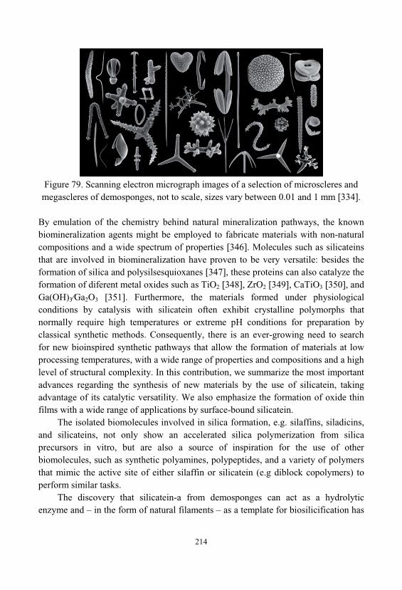
214
Figure 79. Scanning electron micrograph images of a selection of microscleres andmegascleres of demosponges, not to scale, sizes vary between 0.01 and 1 mm [334].
By emulation of the chemistry behind natural mineralization pathways, the knownbiomineralization agents might be employed to fabricate materials with non-naturalcompositions and a wide spectrum of properties [346]. Molecules such as silicateinsthat are involved in biomineralization have proven to be very versatile: besides theformation of silica and polysilsesquioxanes [347], these proteins can also catalyze theformation of diferent metal oxides such as TiO2 [348], ZrO2 [349], CaTiO3 [350], andGa(OH)3 Ga2O3 [351]. Furthermore, the materials formed under physiologicalconditions by catalysis with silicatein often exhibit crystalline polymorphs thatnormally require high temperatures or extreme pH conditions for preparation byclassical synthetic methods. Consequently, there is an ever-growing need to searchfor new bioinspired synthetic pathways that allow the formation of materials at lowprocessing temperatures, with a wide range of properties and compositions and a highlevel of structural complexity. In this contribution, we summarize the most importantadvances regarding the synthesis of new materials by the use of silicatein, takingadvantage of its catalytic versatility. We also emphasize the formation of oxide thinfilms with a wide range of applications by surface-bound silicatein.
The isolated biomolecules involved in silica formation, e.g. silaffins, siladicins, and silicateins, not only show an accelerated silica polymerization from silicaprecursors in vitro, but are also a source of inspiration for the use of otherbiomolecules, such as synthetic polyamines, polypeptides, and a variety of polymersthat mimic the active site of either silaffin or silicatein (e.g diblock copolymers) toperform similar tasks.
The discovery that silicatein-a from demosponges can act as a hydrolyticenzyme and – in the form of natural filaments – as a template for biosilicification has
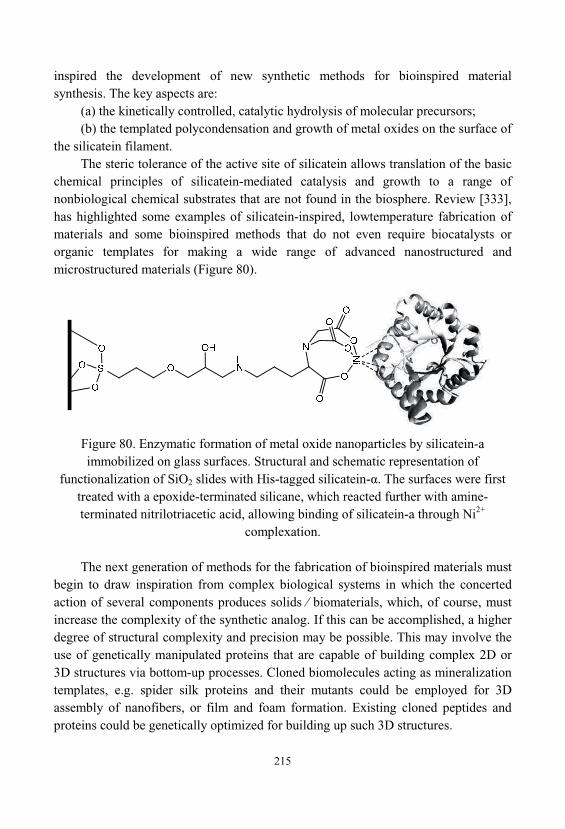
215
inspired the development of new synthetic methods for bioinspired materialsynthesis. The key aspects are:
(a) the kinetically controlled, catalytic hydrolysis of molecular precursors; (b) the templated polycondensation and growth of metal oxides on the surface of
the silicatein filament. The steric tolerance of the active site of silicatein allows translation of the basic
chemical principles of silicatein-mediated catalysis and growth to a range ofnonbiological chemical substrates that are not found in the biosphere. Review [333], has highlighted some examples of silicatein-inspired, lowtemperature fabrication ofmaterials and some bioinspired methods that do not even require biocatalysts ororganic templates for making a wide range of advanced nanostructured andmicrostructured materials (Figure 80).
Figure 80. Enzymatic formation of metal oxide nanoparticles by silicatein-aimmobilized on glass surfaces. Structural and schematic representation of
functionalization of SiO2 slides with His-tagged silicatein- . The surfaces were firsttreated with a epoxide-terminated silicane, which reacted further with amine-terminated nitrilotriacetic acid, allowing binding of silicatein-a through Ni2+
complexation.
The next generation of methods for the fabrication of bioinspired materials mustbegin to draw inspiration from complex biological systems in which the concertedaction of several components produces solids biomaterials, which, of course, mustincrease the complexity of the synthetic analog. If this can be accomplished, a higherdegree of structural complexity and precision may be possible. This may involve theuse of genetically manipulated proteins that are capable of building complex 2D or3D structures via bottom-up processes. Cloned biomolecules acting as mineralizationtemplates, e.g. spider silk proteins and their mutants could be employed for 3Dassembly of nanofibers, or film and foam formation. Existing cloned peptides andproteins could be genetically optimized for building up such 3D structures.

216
217
CONCLUSION
Synthesis and studying of properties of new organic-mineral hybridnanocomposites is of great importance. On the basis of these studies can be foundsolutions to many specific technological problems. Promising areas in the field oforganic-mineral hybrid nanocomposite materials will be methods of synthesis ofmulticomponent materials, as well as materials such as «net in net» and «host-guest». Are promising ways of using alkoxides of various metals, including complex, polynuclear and multi-functional, into the sol-gel processes.
Promising direction of the creation of new nanocomposites is the combination ofinorganic, organic and metal-organic compounds. Especially interesting is the use insuch compositions metallocene compounds. Based on them, may be created chiralmetallocene heterogeneous catalysts. Supramolecular chelate compounds are capableof the cations transport, controlled, by the electrochemical method. Biosensors willbe used for monitoring of industrial fermentation processes, and manufacturing ofanti-cancer drugs with prolonged action. Using this approach can be creatednanocomposite materials with nonlinear optical properties. Also, in this area, there isa fundamental possibility of creating molecular magnets based nanocomposites. Suchmaterials will be able, as a result of external influences, exercise and change theirmagnetic properties. They will be able to exhibit the properties of ferromagnets andantiferromagnets.
The fundamental problem with the chemistry and physics of nanocompositesremains the dependent "composition - structure - property". An important direction inthis area is the development of a theory describing the processes of production andstructure of nanocomposite materials. Solution of this problem allows passing fromresearch of materials to their purposeful designing. At experts from various scientificfields, all over the world, this task causes huge interest and encourages them toactively work on a solution.

218
219
REFERENCES1. Rowcliffe D.J., Fruhauf V. The Fracture of Jade, J. Mater. Sci., Vol. 12, (1977),
pp. 35-42. 2. Iler R.K., Inorganic Colloids for Forming Ultrastructures, Sci. Ceram. Chem.
Process: Proc. 2-nd Int. Conf. Ultrastruct. Process. Ceram, Glasses andCompos., Palm Coast, (1986), pp. 3-20.
3. Iler R.K., Strength and Structure of Flint, Nature, Vol. 199, (1963), pp. 1278-1279. 4. Kerber M.L., Polymer composite materials. Structure. Properties. Technology. – S-
Pb.: Occupation, (2008), 560 p. 5. Friedrich K., Fakirov S., Zhang Z. Polymer composites: from nano-to-macro-scale,
(2005), Springer. 6. Kobayashi N. Introduction to nanotechnology. - M.: BINOM, (2005), – 134 p. 7. Kajiwara Y., Chujo Y. Microwave-enhanced hybridizations of biopolymers with
silica: effective method for rapid preparation and homogeneous dispersion, Polymer Bulletin, (2011), Vol. 66, 8, pp. 1039-1050.
8. Kickelbick G. Introduction to Hybrid Materials, in Hybrid Materials: Synthesis, Characterization, and Applications (ed G. Kickelbick), Wiley-VCH VerlagGmbH & Co. KGaA, Weinheim, Germany, (2007). DOI:10.1002/9783527610495.ch1
9. Pomogailo A.D. Hybrid polymer-inorganic nanocomposites. Russian ChemicalReviews. (2000), Vol. 69, 1, pp. 53-80.
10. Pomogailo A.D., Rosenberg A.S., Uflyand I.E. Metal nanoparticles in polymers, M.: "Chemistry", (2000).
11. Guglielmi M., Kickelbick G., Martucci A. (Eds.), Sol-Gel Nanocomposites, Series: Advances in Sol-Gel Derived Materials and Technologies, (2014), IX, 227p.
12. Hench L.L., West J.K. The sol-gel process, Chem. Rev., (1990), 90, 1, pp. 33–72, DOI: 10.1021/cr00099a003.
13. Sergeev G.B. Nanochemistry, M.: Moscow State University Press, (2003). 14. Tretyakov Y.D., Goodilin E.A. Main directions of fundamental and oriented
research in the field of nanomaterials, Russian Chemical Reviews, 78, 9, (2009), pp. 867-888.
15. http://e-library.ru16. Figovsky O., Beilin D., Advanced Polymer Concretes and Compounds @ CRC
Press, Tailor &Francis Group, 2013, 245 pp.
220
17. Korneev V.I., Danilov V.V. Soluble and waterglass. St. Petersburg: Stroyizdat, 1996.
18. Ayler R. Chemistry of silica, vol. 1-2, M.: MIR, (1982), 416 p. 19. Grigoriev P.N., Matveev M.A. Water glass (production, properties and
application) - Moscow, 1956. 20. Kudryavtsev P.G., Volkhin V.V. The sol-gel process and some of its
technological applications, Sol-gel Processes for the Production of InorganicMaterials, Dokl. seminar, Perm, 1991, pp. 3-5.
21. Christophlienk P. Glastechn. Ber., 1985, 85, N 11, S. 308. 22. Porter M.R., Handbook of Surfactants. Blackie, Glasgow (UK), 1994. 23. Figovsky O.L., Beilin D.A., Ponomarev A.N. Successful application of
nanotechnology in construction materials, Nanotechnology in Construction(Nanobuild), 3, (2012), pp. 6-21.
24. Kudryavtsev P.G., Kavalerova O.B. Methods for the preparation of solsoxyhydrates metals used as binders for forming inorganic composites, Proc. Scien. works. Composite materials based on dispersed systems, Ekaterinburg, Ural Branch of Russian Academy of Sciences, 1994, pp. 21-29.
25. Bazhenov A.V. Colloid-chemical basis of continuous ion exchange technologyhydrosol silica, Diss. cand. chem. Sciences. M .. MChTI them. D.I. Mendeleev, 1978.
26. Dzisko V.A. Fundamentals of catalyst preparation. Novosibirsk: Nauka, 1983, 263 p.
27. Preparation and use of silica hydrosols. Ed. prof. Frolov Yu.G. ProceedingsMChTI them. D.I. Mendeleev, M., 1979, 137 p.
28. Pospelov A.A., Skorokhodova I.E. Method of preparation of the sol of silicic acidused for forming the inorganic sorbents. Proc.: Chemistry and technology ofinorganic sorbents, Perm, PPI, 1979, pp. 92-94.
29. Pospelov A.A., Galkin Y.M. Analysis of the methods of preparation anddevelopment of non-waste technology acidic silica sol. In Coll.: Chemicalpreparation of refractory materials. L.: LTI, 1984, pp. 33 - 41.
30. Laib D.F. U.S. Patent No. 4,124,471. Controlling the size of particles of silica sol. 22.08.77, publ. 11/07/78, MKI 01 D 13/02.
31. Lacy R.I., Loeb S. in the book: Processes using membranes. M.: Mir, 1976. 32. Lipkind V.A., Drozhzhennikov S.V. Production of silica sol electrodialysis
method. Proceedings MChTI them. D.I. Mendeleyev, M., 1979, pp. 26-31. 33. Schenker X.A. US Patent 4147605 A method of manufacturing an electrodialysis
sols. Appl. 14.04.77., Publ. 03.04.79, MKI 01 13/02.
221
34. Frolov Yu.G., Grodsky A.S. Preparation hydrosols of silica and zirconia by ionexchange, electrodialysis combined with. Proceedings MChTI them. D.I. Mendeleev, M., 1979.
35. Pospelov A.A., Krylov V.N. Application of sol and sol-gel methods in synthesistechnology 20. sorbents. Proc.: Chemistry and technology of inorganic sorbents. Perm, PPI, 1979.
36. Kudryavtsev P.G., Kavalerova O.B. Kazakova I.L., Volkhin V.V. Preparation andstabilization of solutions of metal oxides Seminar: The sol-gel processes for theproduction of inorganic materials, Perm, 1991, p.33.
37. Gordova I.R., Kondratiev Yu., Kurkin V.P. Inorganic glass and products based onthem for the fiber-optic communication systems and sensors. In Sat: Technologyof silicate and refractory nonmetallic materials (in Science and TechnologyVINITI)., 1989, vol. 2, p. 175.
38. Preparation of high purity aluminum oxide: an overview. Series: The reagents andhighly purified substances. M.: NIITHIM, 1987, 40 p.
39. Kudryavtsev P.G. Alkoxides of chemical elements - promising class of chemicalcompounds wich are raw materials for Hi-Tech industries; Journal "ScientificIsrael - Technological Advantages", Vol. 16, N 2, 2014, p. 147-170
40. Sears G.W. Determination of Specific Surface Area of Colloidal Silica byTitration with Sodium Hydroxide, Anal. Chem., 1956, 28 (12), pp 1981–1983, DOI: 10.1021/ac60120a048.
41. Kudryavtsev P.G., Kavalerova O.B. The dynamics of changes in the particle sizeof polymers in inorganic solutions Conf.: Formation of surface and interfacialinteraction composites Izhevsk, 1988, p.58.
42. Frolov Yu.G., Shabanov N.A., Molodchikova S.I. Patterns of change in theviscosity of silica hydrosols // Colloid. Zh., 1983. V. 45, 5. pp. 970-975.
43. Kudryavtsev P.G., Koltakov A.I. Rheological studies gelation Reofizika andthermal physics of nonequilibrium systems - 4.1 Non-equilibrium processes inheterogeneous environments: materials Intern. School-Seminar, Minsk, 1991, p.164.
44. Levitsky M., Zavin B.G., Bilyachenko A.N. Chemistry metallorganosiloksanov. Modern trends and new concepts, Russian Chemical Reviews, 76 (2007), s.907-926
45. Bradley D.C., Mehrotra R.C., Rothwell I., Singh A. Aryloxo Derivatives ofMetals, Academic Press, 2001.
46. Mehrotra R. ., Singh A.. Organometallic Chemistry, NAI, 2004, 617p. 47. Bradley D. , Fisher .J., . .P. International Rev. Sci. General Chem. of
Transition Metals, ed. D.W.A. Sharp, 5, part 1, Butterworths, London, (1972), 65.
222
48. Turova N.Y., Novoselova A.V. Alcohol derivatives of alkali, alkaline earthmetals, magnesium and thallium (I), Russian Chemical Reviews, V.34, 3, 1965, pp. 385-433.
49. Penckos R. Aluminum alkoxides, Russian Chemical Reviews, 37, 4, (1968), pp. 647-676.
50. Bradley D.C. Metal Alkoxides and Dialkylamides, Advances in Inorg. Chem. andRadiochem., 15, (1972), 259.
51. ussaint R., Rev. chim. industr., 39, (1930), 162. 52. ussaint R., Rev. chim. industr., 39, (1930), 226. 53. ussaint R., Rev. chim. industr., 39, (1930), 290. 54. ussaint R., Rev. chim. industr., 39, (1930), 322. 55. Byrkit G.D., Soule E. ., Chem. and Eng. News, 22, 1903 (1944). 56. Ivanov, S.V. Preparation of very pure starting materials for nanotechnology,
Moscow, RF, (2005). 57. Strelnikova, I.E. Highly purified metal alcoholates to obtain oxide systems,
Moscow (2005). 58. Roco M.K., Williams R.S. and Alivisatos P. Nanotechnology in the next decade.
Forecast research directions. M., MIR, (2002). 59. Belyakov A.B. Methods of preparation of inorganic non-metallic nanoparticles.
M., Ed. Center RCTU. D.I.Mendeleev (2003). 60. Pool B., Owens F. Nanotechnology, M., Technosphere, (2004). 61. Andrianov K.A. Methods of Hetero-organic Chemistry. Silicon - Nauka, Moscow
(1968)62. Tretyakov Yu.D. Self-organization processes in the chemistry of materials, Russ.
Chem. Rev., 72, (2003), 65163. Suzdalev I.P., Suzdalev P.I. Discreteness of nanostructures and critical
dimensions of nanoclusters, Russian Chemical Reviews, 75, (2006), pp. 715. 64. Dimitriev Y. Ivanova Y. Iordanova R. History of sol-gel science and technology
(review). J. Univ. Chem. Technol. Metall., (2008), 43, pp.181–19265. Livage J., Henry M., Sanchez C. Sol-gel chemistry of transition metal oxides.
Prog. Solid State., (1988), 18, 4, pp. 259–341. doi:10.1016/0079-6786(88)90005-2
66. Blesa M.A., Candal R.J. Powder production from aqueous solutions for ceramicsapplication. Miguel A. Blesa et al., Key Engineering Materials, 1991, 58, 107–128. doi:10.4028/www.scientific.net/KEM.58.107
67. Hirano S.. Hydrothermal processing of ceramics. Am. Ceram. Soc. Bull., 1987, Vol. 66, 9, pp. 1342–1344
68. Somiya S., Roy R. Hydrothermal synthesis of fine oxide powders. Bull. Mater. Sci., (2000), 23, 6, p.453–460. doi:10.1007/BF02903883
223
69. Lakeman C.D.E., Payne D.A.. Sol-gel processing of electrical and magneticceramics. Mater. Chem. Phys., (1994), 38, 4, p. 305–324. doi:10.1016/0254-0584(94)90207-0
70. Livage J., Beteille F., Roux C., Chatry M., Davidson P. Sol-gel synthesis of oxidematerials. Acta. Mater., (1998), 46, 3, pp.743–750. doi:10.1016/S1359-6454(97)00255-3
71. Komarneni S., Abothu I.R., Rao A.V.P. Sol-gel processing of someelectroceramic powders. J Sol-Gel Sci. Technol., (1999), 15, 3, pp.263–270
72. Lee G.R., Crayston J.A. Sol-gel processing of transition-metal alkoxides forelectronics. Adv. Mater. (Weinheim, Fed Repub Ger), (1993), 5, 6, (1993), 434–442. doi:10.1002/adma.19930050604
73. Sakka S. Sol-gel coating films for optical and electronic application. StructBonding (Berlin) 85(Optical and electronic phenomena in sol-gel glasses andmodern application), (1996), 1–49
74. Levy D., Esquivias L. Sol-gel processing of optical and electrooptical materials. Adv Mater (Weinheim, Ger), (1995), 7, 2, pp.120–129. doi: 10.1002/adma. 19950070204
75. Brinker C.J., Scherer G.W. Sol-gel science: the physics and chemistry of sol-gelprocessing. Access online via Elsevier, (1990).
76. Nemeth S.. Processing and mechanical properties of hybrid sol-gel-derivednanocomposite coatings. CRC Press, Boca Raton, (2010), pp. 147–204
77. Glaubitt W., Loebmann P. Antireflective coatings prepared by sol-gel processing:principles and applications. J Eur Ceram Soc., (2012), 32(11),p.2995–2999. doi:10.1016/j.jeurceramsoc.2012.02.032
78. Cushing B..L, Kolesnichenko V.L, O’Connor C.J. Recent advances in the liquid-phase syntheses of inorganic nanoparticles. Chem. Rev. (Washington, DC, U S), (2004), 104, 9, pp.3893–3946. doi:10.1021/cr030027b
79. Niederberger M. Nonaqueous sol-gel routes to metal oxide nanoparticles. AccChem Res., (2007), 40(9):793–800. doi:10.1021/ar600035e
80. Sanchez C., Rozes L., Ribot F., Laberty-Robert C., Grosso D., Sassoye C., Boissiere C., Nicole L. ‘‘Chimie douce’’: a land of opportunities for thedesigned construction of functional inorganic and hybrid organic-inorganicnanomaterials. C.R.Chim., (2010), 13, 1–2, pp.3–39. doi:10.1016/j.crci. 2009.06.001
81. Kickelbick G. (Editor). Hybrid Materials: Synthesis, Characterization, andApplications, (2007), Wiley, 516 p.
82. Amphlett C.B.. Inorganic ion exchangers, Elsevier, Amsterdam, 1964. 83. Tanabe K. Solid Acids and basis. Their catalytic properties, Kodansha, Tokyo,
1970.
224
84. Mandelbrot B. - Fractal Geometry of Nature - M., IKI, 2002, 656 p. 85. Elshenbroyh K. Organometallic chemistry, M., BINOM, 2011, 746 p. 86. Smith M.B. March's Advanced Organic Chemistry: Reactions, Mechanisms, and
Structure, 7th Edition, (2013), 2080 p. 87. Loy D.A., Shea K.J. Bridged polysilsesquioxanes. Highly porous hybrid organic-
inorganic materials. Chem Rev (Washington, D C), (1995), 95(5), pp.1431–1442. doi:10.1021/cr00037a013
88. Pomogailo A.D. Polymer sol-gel synthesis of hybrid nanocomposites, ColloidJournal. (2005), Vol. 67. 6. pp. 658-677.
89. Aegerter M.A. Leventis N. Koebel M.M. eds. Aerogels handbook, Springer, (2011), 965 p.
90. Yoshiki Chujo, Takeo Saegusa Advances in Polymer Science, (1992), Vol. 100, .11 - 29.
91. Hay J.N., Raval H.M. Synthesis of organic-inorganic hybrids via thenonhydrolytic solgel process. Chem. Mater., (2001), 13(10), pp.3396–3403. doi:10.1021/cm011024n
92. Acosta S., Arnal P., Corriu R.J P., Leclercq D., Mutin P. H. and Vioux A.J. Mater. Res. Soc. Symp. Proc., (1994), Vol. 43, P. 346.
93. Corriu R.J.P., Leclercq D., Lefèvre P., Mutin P.H., ViouxA. Preparation ofmonolithic gels from silicon halides by a non-hydrolytic sol-gel process, J. Non-Cryst. Solids, Vol. 146, (1992), P. 301–303.
94. Andrianainarivelo M., Corriu R.J.P., Leclercq D., Mutin P.H., Vioux A. Nonhydrolytic Sol-Gel process: Aluminium and zirconium titanate gelsJournalof Sol-Gel Science and Technology, (1997), Volume 8, Issue 1-3, pp 89-93.
95. Anil K.P.S., Alias J.P., Date S.K. Effect of compositional homogeneity on themagnetic propertiesof La0.7Ca0.3MnO3. J. Mater. Chem., (1998), 8, 1219-1223, DOI: 10.1039/A708235E .
96. Hay J.N., Raval H.M. Preparation of Inorganic Oxides via a Non-Hydrolytic Sol-Gel Route, Journal of Sol-Gel Science and Technology, (1998), Vol. 13, Issue 1-3, pp 109-112.
97. Arnal P., Corriu R.J.P., Leclercq D., Mutin P.H. and Vioux A. Preparation ofanatase, brookite and rutile at low temperature by non-hydrolytic sol–gelmethods. J. Mater. Chem., (1996), 6, p.1925-1932, DOI:10.1039/JM9960601925.
98. Jansen M., Guenther E. Oxide Gels and Ceramics Prepared by a NonhydrolyticSol-Gel Process, Chemistry of Materials, 1995, Vol. 7, 11, pp.2110-2114, DOI:10.1021/cm00059a019
99. Andrianov K.A. Silicone compounds. - M.: State Scientific - TechnicalPublishing chemical literature (1955).
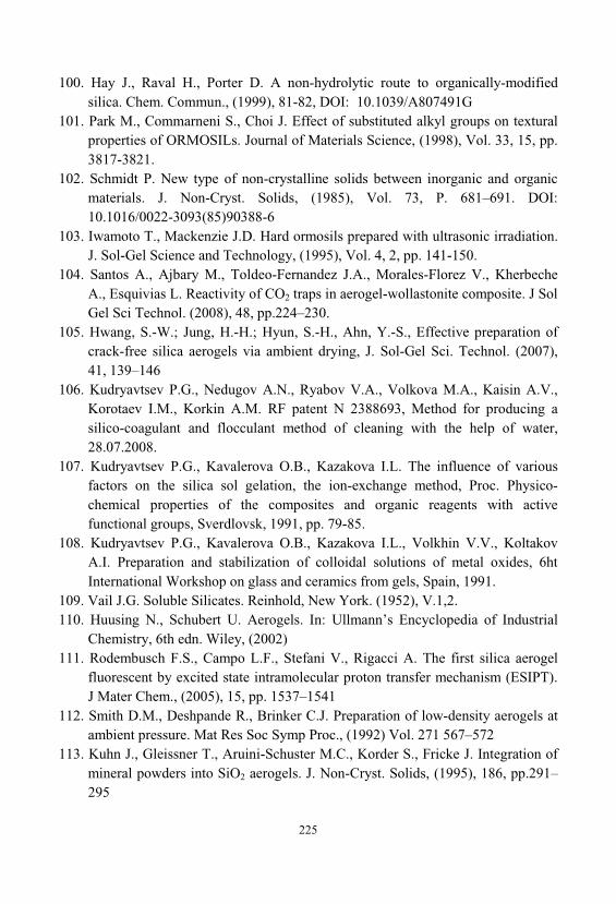
225
100. Hay J., Raval H., Porter D. A non-hydrolytic route to organically-modifiedsilica. Chem. Commun., (1999), 81-82, DOI: 10.1039/A807491G
101. Park M., Commarneni S., Choi J. Effect of substituted alkyl groups on texturalproperties of ORMOSILs. Journal of Materials Science, (1998), Vol. 33, 15, pp. 3817-3821.
102. Schmidt . New type of non-crystalline solids between inorganic and organicmaterials. J. Non-Cryst. Solids, (1985), Vol. 73, P. 681–691. DOI:10.1016/0022-3093(85)90388-6
103. Iwamoto T., Mackenzie J.D. Hard ormosils prepared with ultrasonic irradiation. J. Sol-Gel Science and Technology, (1995), Vol. 4, 2, pp. 141-150.
104. Santos A., Ajbary M., Toldeo-Fernandez J.A., Morales-Florez V., KherbecheA., Esquivias L. Reactivity of CO2 traps in aerogel-wollastonite composite. J SolGel Sci Technol. (2008), 48, pp.224–230.
105. Hwang, S.-W.; Jung, H.-H.; Hyun, S.-H., Ahn, Y.-S., Effective preparation ofcrack-free silica aerogels via ambient drying, J. Sol-Gel Sci. Technol. (2007), 41, 139–146
106. Kudryavtsev P.G., Nedugov A.N., Ryabov V.A., Volkova M.A., Kaisin A.V., Korotaev I.M., Korkin A.M. RF patent N 2388693, Method for producing asilico-coagulant and flocculant method of cleaning with the help of water, 28.07.2008.
107. Kudryavtsev P.G., Kavalerova O.B., Kazakova I.L. The influence of variousfactors on the silica sol gelation, the ion-exchange method, Proc. Physico-chemical properties of the composites and organic reagents with activefunctional groups, Sverdlovsk, 1991, pp. 79-85.
108. Kudryavtsev P.G., Kavalerova O.B., Kazakova I.L., Volkhin V.V., KoltakovA.I. Preparation and stabilization of colloidal solutions of metal oxides, 6htInternational Workshop on glass and ceramics from gels, Spain, 1991.
109. Vail J.G. Soluble Silicates. Reinhold, New York. (1952), V.1,2. 110. Huusing N., Schubert U. Aerogels. In: Ullmann’s Encyclopedia of Industrial
Chemistry, 6th edn. Wiley, (2002)111. Rodembusch F.S., Campo L.F., Stefani V., Rigacci A. The first silica aerogel
fluorescent by excited state intramolecular proton transfer mechanism (ESIPT). J Mater Chem., (2005), 15, pp. 1537–1541
112. Smith D.M., Deshpande R., Brinker C.J. Preparation of low-density aerogels atambient pressure. Mat Res Soc Symp Proc., (1992) Vol. 271 567–572
113. Kuhn J., Gleissner T., Aruini-Schuster M.C., Korder S., Fricke J. Integration ofmineral powders into SiO2 aerogels. J. Non-Cryst. Solids, (1995), 186, pp.291–295
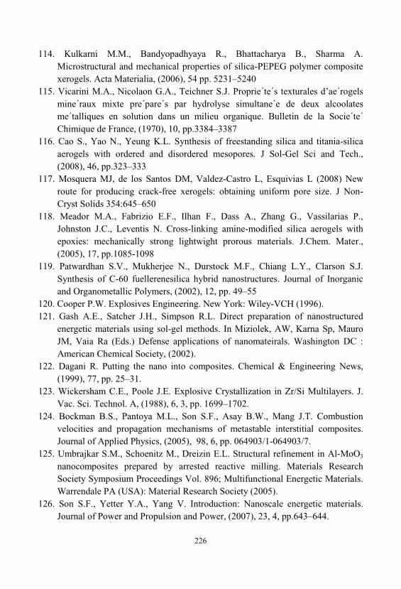
226
114. Kulkarni M.M., Bandyopadhyaya R., Bhattacharya B., Sharma A. Microstructural and mechanical properties of silica-PEPEG polymer compositexerogels. Acta Materialia, (2006), 54 pp. 5231–5240
115. Vicarini M.A., Nicolaon G.A., Teichner S.J. Proprie´te´s texturales d’ae´rogelsmine´raux mixte pre´pare´s par hydrolyse simultane´e de deux alcoolatesme´talliques en solution dans un milieu organique. Bulletin de la Socie´te´Chimique de France, (1970), 10, pp.3384–3387
116. Cao S., Yao N., Yeung K.L. Synthesis of freestanding silica and titania-silicaaerogels with ordered and disordered mesopores. J Sol-Gel Sci and Tech., (2008), 46, pp.323–333
117. Mosquera MJ, de los Santos DM, Valdez-Castro L, Esquivias L (2008) Newroute for producing crack-free xerogels: obtaining uniform pore size. J Non-Cryst Solids 354:645–650
118. Meador M.A., Fabrizio E.F., Ilhan F., Dass A., Zhang G., Vassilarias P., Johnston J.C., Leventis N. Cross-linking amine-modified silica aerogels withepoxies: mechanically strong lightwight prorous materials. J.Chem. Mater., (2005), 17, pp.1085-1098
119. Patwardhan S.V., Mukherjee N., Durstock M.F., Chiang L.Y., Clarson S.J. Synthesis of C-60 fuellerenesilica hybrid nanostructures. Journal of Inorganicand Organometallic Polymers, (2002), 12, pp. 49–55
120. Cooper P.W. Explosives Engineering. New York: Wiley-VCH (1996). 121. Gash A.E., Satcher J.H., Simpson R.L. Direct preparation of nanostructured
energetic materials using sol-gel methods. In Miziolek, AW, Karna Sp, MauroJM, Vaia Ra (Eds.) Defense applications of nanomateirals. Washington DC :American Chemical Society, (2002).
122. Dagani R. Putting the nano into composites. Chemical & Engineering News, (1999), 77, pp. 25–31.
123. Wickersham C.E., Poole J.E. Explosive Crystallization in Zr/Si Multilayers. J. Vac. Sci. Technol. A, (1988), 6, 3, pp. 1699–1702.
124. Bockman B.S., Pantoya M.L., Son S.F., Asay B.W., Mang J.T. Combustionvelocities and propagation mechanisms of metastable interstitial composites. Journal of Applied Physics, (2005), 98, 6, pp. 064903/1-064903/7.
125. Umbrajkar S.M., Schoenitz M., Dreizin E.L. Structural refinement in Al-MoO3
nanocomposites prepared by arrested reactive milling. Materials ResearchSociety Symposium Proceedings Vol. 896; Multifunctional Energetic Materials. Warrendale PA (USA): Material Research Society (2005).
126. Son S.F., Yetter Y.A., Yang V. Introduction: Nanoscale energetic materials. Journal of Power and Propulsion and Power, (2007), 23, 4, pp.643–644.

227
127. Aumann C.E., Skofronick G.L., Martin J.A. Oxidation behavior of aluminumnanopowders. J. Vac. Sci. Technol. B. (1993), 13, 2, pp.1178–1183.
128. Armstrong R.W., Coffey C.S., DeVost V.F., Elban W.L. Crystal sizedependences for the impact initiation of cyclotrimethylenetrimitramineexplosive. J. Appl. Phys., (1990), 68, pp. 979–984.
129. Maxwell Garnett J.C. Colors in metal glasses and in metallic films. Philosophical Transactions Royal Society of London, (1904), A203, pp. 385–420.
130. Figovsky O., Kudryavtsev P. Advanced nanomaterials based on soluble silicates, Journal "Scientific Israel - Technological Advantages", Vol.16, no.3, 2015, pp.36-76.
131. Cherenkov PA Visible radiation produced by electrons moving in a mediumwith velocities exceeding that of light. Phys. Rev. (1937). 52. Pp. 378–379.
132. Carlson P. Aerogel Cherenkov counters: construction principles andapplications. Nucl. Instrum. Methods Phys. Res., (1986), Sect A248, pp. 110–117.
133. Gunter P. Aerogel Cherenkov counters at DESY. Nucl Instr. and Meth., (1986), A248, pp.118–129
134. Anderson M.L., Rolison D.R., Merzbacher C.I. Composite aerogels for sensingapplications. Proc. SPIE. (1999), 3790, pp. 38–42.
135. Woignier T., Phalippou J., and Prassas M. Glasses from aerogels part 2: Theaerogel glass transformation. J. Mater. Sci., (1990), 25 pp. 3118–3126.
136. Zanotto E.D. The formation of unusual glasses by sol-gel processing. J. Non-Cryst. Solids, (1992), 147&148, pp. 820–823
137. Boday D.J. Loy D.A. Poly aniline nanofiber/silica aerogel composites withimproved strength and sensor applications. Polymer Preprints, (2009), 50, p. 282.
138. Woignier T., Reynes J., Phalippou J., Dussossoy J.L., Jacquet-Francillon N. Sintered silica aerogel: a host matrix for long live nuclear wastes. J. Non-Cryst. Solids, (1998), 225, pp. 353–357
139. Hoebbel, D., Garzó, G., Engelhardt, G., Ebert, R., Lippmaa, E. and Alla, M. (1980), Über die Silicatanionenkonstitution in Tetraethylammoniumsilicatenund ihren wäßrigen Lösungen. Z. anorg. allg. Chem., 465: 15–33. doi:10.1002/zaac.19804650103
140. Hoebbel, D., Vargha, A., Engelhardt, G. and Ujszászy, K. (1984), ZumAnionenaufbau von Tetra-n-butylammoniumsilicaten und ihren wäßrigenLösungen. Z. anorg. allg. Chem., 509: 85–94. doi: 10.1002/zaac.19845090209
141. Schulze B., Tisher B., Ettel V.P. Mortars and concretes on non cementitiousbinders. M.: Stroyizdat, 1990. 240 p.
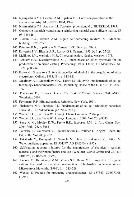
228
142. Nyanyushkin Y.I., Levshin A.M., Epstein V.S. Corrosion protection in thechemical industry, M., NIITEKHIM, 1976.
143. Nyanyushkin Y.I., Anatsky F.I. Corrosion protection, M., NIITEKHIM, 1983. 144. Composite materials comprising a reinforcing material and a silicate matrix, EP
0310354 B1. 145. Borsuk P.A., Ribbon A.M. Liquid self-hardening mixture. M.: Machine-
building, 1979. 255 p. 146. Petrakov B.N., Lopatkin A.V. Cement, 1993. 9. pp. 38-39. 147. Krivenko P.V., Blazhis A.R., Rostov G.S. Cement, 1993. 1, pp 27-29. 148. Melikhov I.V., Merkulov M.S., Co-crystallization, Nauka, Moscow, 1975. 149. Lebtsev E.N., Kleschevnikova S.I., Binder based on silica hydrosols for the
production of precision casting. Proceedings MChTI them. D.I.Mendeleev. M., 1979, p. 83-84.
150. Frolov G., Shabanova N. Sensitizing effect of alcohol in the coagulation of silicaelectrolytes. Coll.zh., 1983, N 4, p. 818-821.
151. Maximov A.I., Moshnikov V.A., Tairov M., Shilov O. Fundamentals of sol-geltechnology nanocomposites S-Pb.: Publishing House of the ETU "LETI", 2007. 156 p.
152. Platikanov D., Exerova D. eds. The Best of Colloid Science, Wiley-VCH, Weinheim, 2009.
153. Feynmann R.P. Miniaturization, Reinhold, New York, 1961. 154. Shabanova N.A., Sarkisov P.D. Fundamentals of sol-gel technology nanosized
silica, M., ICC "Akademkniga", 2004, 208 p. 155. Worden J.G., Shaffer A.W., Huo Q. Chem. Commun., 2004, p.518. 156. Worden J.G., Shaffer A.W., Huo Q. Langmuir, 2004, Vol. 20, p.8343. 157. Sung K.-M., Mosley D.W., Peelle B.R., Jacobson J.M. J. Am. Chem. Soc.,
2004, Vol. 126, p. 5064158. Patolsky F., Weizmann Y., Lioubashevshi O., Willner I. Angew. Chem. Int.
Ed., 2002, Vol. 41, p. 2323. 159. Takahashi Y„ Kobayashi I., Noguchi M., Hirai N„ Nakanishi K„ Hattori M.
Water purifying apparatus. EP 504597. AO 1K63/04, (1992). 160. Self-setting aqueous mixtures for the manufacture of chemically resistant
materials, and their manufacture and use. (Woellner-Werke GmbH und Co.) DE4104596, C04B28/24, (1992).
161. Kubota Y., Helmkamp M.M., Zones S.I., Davis M.E. Properties of organiccations that lead to the structure-direction of high-silica molecular sieves. Microporous Materials, (1996), 6, 4, 213-229.
162. Westall S. Process for producing organosiloxanes. EP 587343, C08G77/08, (1994).
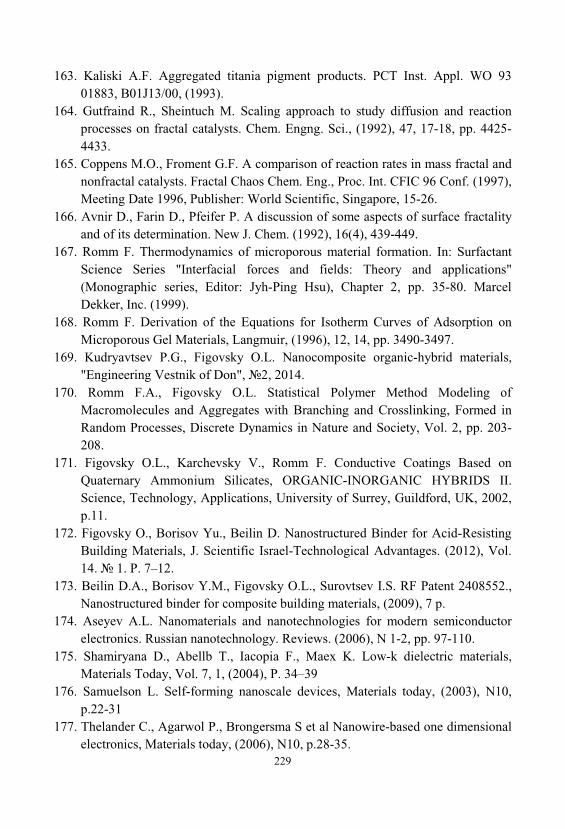
229
163. Kaliski A.F. Aggregated titania pigment products. PCT Inst. Appl. WO 9301883, B01J13/00, (1993).
164. Gutfraind R., Sheintuch M. Scaling approach to study diffusion and reactionprocesses on fractal catalysts. Chem. Engng. Sci., (1992), 47, 17-18, pp. 4425-4433.
165. Coppens M.O., Froment G.F. A comparison of reaction rates in mass fractal andnonfractal catalysts. Fractal Chaos Chem. Eng., Proc. Int. CFIC 96 Conf. (1997), Meeting Date 1996, Publisher: World Scientific, Singapore, 15-26.
166. Avnir D., Farin D., Pfeifer P. A discussion of some aspects of surface fractalityand of its determination. New J. Chem. (1992), 16(4), 439-449.
167. Romm F. Thermodynamics of microporous material formation. In: SurfactantScience Series "Interfacial forces and fields: Theory and applications"(Monographic series, Editor: Jyh-Ping Hsu), Chapter 2, pp. 35-80. MarcelDekker, Inc. (1999).
168. Romm F. Derivation of the Equations for Isotherm Curves of Adsorption onMicroporous Gel Materials, Langmuir, (1996), 12, 14, pp. 3490-3497.
169. Kudryavtsev P.G., Figovsky O.L. Nanocomposite organic-hybrid materials, "Engineering Vestnik of Don", 2, 2014.
170. Romm F.A., Figovsky O.L. Statistical Polymer Method Modeling ofMacromolecules and Aggregates with Branching and Crosslinking, Formed inRandom Processes, Discrete Dynamics in Nature and Society, Vol. 2, pp. 203-208.
171. Figovsky O.L., Karchevsky V., Romm F. Conductive Coatings Based onQuaternary Ammonium Silicates, ORGANIC-INORGANIC HYBRIDS II. Science, Technology, Applications, University of Surrey, Guildford, UK, 2002, p.11.
172. Figovsky O., Borisov Yu., Beilin D. Nanostructured Binder for Acid-ResistingBuilding Materials, J. Scientific Israel-Technological Advantages. (2012), Vol. 14. 1. P. 7–12.
173. Beilin D.A., Borisov Y.M., Figovsky O.L., Surovtsev I.S. RF Patent 2408552., Nanostructured binder for composite building materials, (2009), 7 p.
174. Aseyev A.L. Nanomaterials and nanotechnologies for modern semiconductorelectronics. Russian nanotechnology. Reviews. (2006), N 1-2, pp. 97-110.
175. Shamiryana D., Abellb T., Iacopia F., Maex K. Low-k dielectric materials, Materials Today, Vol. 7, 1, (2004), P. 34–39
176. Samuelson L. Self-forming nanoscale devices, Materials today, (2003), N10, p.22-31
177. Thelander C., Agarwol P., Brongersma S et al Nanowire-based one dimensionalelectronics, Materials today, (2006), N10, p.28-35.
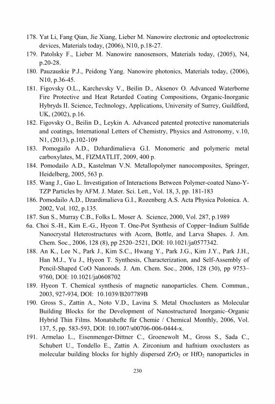
230
178. Yat Li, Fang Qian, Jie Xiang, Lieber M. Nanowire electronic and optoelectronicdevices, Materials today, (2006), N10, p.18-27.
179. Patolsky F., Lieber M. Nanowire nanosensors, Materials today, (2005), N4, p.20-28.
180. Pauzauskie P.J., Peidong Yang. Nanowire photonics, Materials today, (2006), N10, p.36-45.
181. Figovsky O.L., Karchevsky V., Beilin D., Aksenov O. Advanced WaterborneFire Protective and Heat Retarded Coating Compositions, Organic-InorganicHybryds II. Science, Technology, Applications, University of Surrey, Guildford, UK, (2002), p.16.
182. Figovsky O., Beilin D., Leykin A. Advanced patented protective nanomaterialsand coatings, International Letters of Chemistry, Physics and Astronomy, v.10, N1, (2013), p.102-109
183. Pomogailo A.D., Dzhardimalieva G.I. Monomeric and polymeric metalcarboxylates, M., FIZMATLIT, 2009, 400 p.
184. Pomodailo A.D., Kastelman V.N. Metallopolymer nanocomposites, Springer, Heidelberg, 2005, 563 p.
185. Wang J., Gao L. Investigation of Interactions Between Polymer-coated Nano-Y-TZP Particles by AFM. J. Mater. Sci. Lett., Vol. 18, 3, pp. 181-183
186. Pomodailo A.D., Dzardimalieva G.I., Rozenberg A.S. Acta Physica Polonica. A. 2002, Vol. 102, p.135.
187. Sun S., Murray C.B., Folks L. Moser A. Science, 2000, Vol. 287, p.19896 . Choi S.-H., Kim E.-G., Hyeon T. One-Pot Synthesis of Copper−Indium Sulfide
Nanocrystal Heterostructures with Acorn, Bottle, and Larva Shapes. J. Am. Chem. Soc., 2006, 128 (8), pp 2520–2521, DOI: 10.1021/ja0577342.
188. An K., Lee N., Park J., Kim S.C., Hwang Y., Park J.G., Kim J.Y., Park J.H., Han M.J., Yu J., Hyeon T. Synthesis, Characterization, and Self-Assembly ofPencil-Shaped CoO Nanorods. J. Am. Chem. Soc., 2006, 128 (30), pp 9753–9760, DOI: 10.1021/ja0608702
189. Hyeon T. Chemical synthesis of magnetic nanoparticles. Chem. Commun., 2003, 927-934, DOI: 10.1039/B207789B
190. Gross S., Zattin A., Noto V.D., Lavina S. Metal Oxoclusters as MolecularBuilding Blocks for the Development of Nanostructured Inorganic–OrganicHybrid Thin Films. Monatshefte für Chemie / Chemical Monthly, 2006, Vol. 137, 5, pp. 583-593, DOI: 10.1007/s00706-006-0444-x.
191. Armelao L., Eisenmenger-Dittner C., Groenewolt M., Gross S., Sada C., Schubert U., Tondello E., Zattin A. Zirconium and hafnium oxoclusters asmolecular building blocks for highly dispersed ZrO2 or HfO2 nanoparticles in
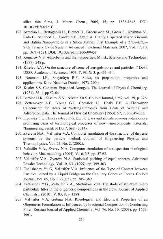
231
silica thin films, J. Mater. Chem., 2005, 15, pp. 1838-1848, DOI: 10.1039/B500521C .
192. Armelao L., Bertagnolli H., Bleiner D., Groenewolt M., Gross S., Krishnan V., Sada C., Schubert U., Tondello E., Zattin A. Highly Dispersed Mixed Zirconiaand Hafnia Nanoparticles in a Silica Matrix: First Example of a ZrO2–HfO2–SiO2 Ternary Oxide System. Advanced Functional Materials, 2007, Vol. 17, 10, pp. 1671–1681, DOI: 10.1002/adfm.200600458
193. Komarov V.S. Adsorbents and their properties. Minsk, Science and Technology, (1977), 248 p.
194. Kiselev A.V. On the structure of some of xerogels pores and particles // Dokl. USSR Academy of Sciences. 1953, T. 98, 3. p. 431-434.
195. Neumark I.E., Sheynfayn R.Y. Silica, its preparation, properties andapplications. Kiev: Naukova Dumka, 1973. 200 p.
196. Kistler S.S. Coherent Expanded-Aerogels. The Journal of Physical Chemistry. (1931), 36, 1, pp.52-64.
197. Berbice H.K., Kiselev A.V., Nikitin Yu.S. Colloid Journal, 1967, vol. 29, p. 326. 198. Zettemover .C., Young G.J., Chessick J.J., Heal F.H. A Thermistor
Calorimeter for Heats of Wetting.Entropies from Heats of Wetting andAdsorption Data. The Journal of Physical Chemistry (1953), 57, 7, pp.649-652.
199. Figovsky O.L., Kudryavtsev P.G. Liquid glass and silicate aqueous solution as apromising basis of technological processes of new nanocomposite materials, "Engineering vestik of Don", 2, (2014).
200. Zvereva N.A., Val’tsifer V.A. Computer simulation of the structure of dispersesystems by the particle method. Journal of Engineering Physics andThermophysics, Vol. 75, No. 2, (2002).
201. Valtsifer V.A., Zverev N.A. Computer simulation of a suspension rheologicalbehavior. Mat. modeling. (2004), V.16, N3, pp. 57-62.
202. Val’tsifer V.A., Zvereva N.A. Statistical packing of equal spheres. AdvancedPowder Technology, Vol.10, N4, (1999), pp. 399-403
203. Tselishchev Yu.G, Val’tsifer V.A. Influence of the Type of Contact betweenParticles Joined by a Liquid Bridge on the Capillary Cohesive Forces. ColloidJournal, Vol. 65, No. 3, (2003), pp. 385–389.
204. Tselischev Y.G., Valtsifer V.A., Strelnikov V.N. The study of structure microparticulate filler in the oligomeric compositions in the flow. Journal of AppliedChemistry. (2010), V. 83, 8, p. 1288
205. Val’tsifer V.A, Gubina N.A. Rheological and Electrical Properties of anOligomeric Formulation as Influenced by Fractional Composition of ConductingFiller. Russian Journal of Applied Chemistry, Vol. 76, No. 10, (2003), pp. 1659-1661.
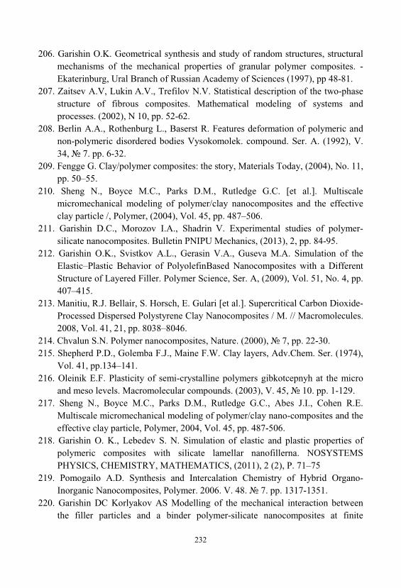
232
206. Garishin O.K. Geometrical synthesis and study of random structures, structuralmechanisms of the mechanical properties of granular polymer composites. -Ekaterinburg, Ural Branch of Russian Academy of Sciences (1997), pp 48-81.
207. Zaitsev A.V, Lukin A.V., Trefilov N.V. Statistical description of the two-phasestructure of fibrous composites. Mathematical modeling of systems andprocesses. (2002), N 10, pp. 52-62.
208. Berlin A.A., Rothenburg L., Baserst R. Features deformation of polymeric andnon-polymeric disordered bodies Vysokomolek. compound. Ser. A. (1992), V. 34, 7. pp. 6-32.
209. Fengge G. Clay/polymer composites: the story, Materials Today, (2004), No. 11, pp. 50–55.
210. Sheng N., Boyce M.C., Parks D.M., Rutledge G.C. [et al.]. Multiscalemicromechanical modeling of polymer/clay nanocomposites and the effectiveclay particle /, Polymer, (2004), Vol. 45, pp. 487–506.
211. Garishin D.C., Morozov I.A., Shadrin V. Experimental studies of polymer-silicate nanocomposites. Bulletin PNIPU Mechanics, (2013), 2, pp. 84-95.
212. Garishin O.K., Svistkov A.L., Gerasin V.A., Guseva M.A. Simulation of theElastic–Plastic Behavior of PolyolefinBased Nanocomposites with a DifferentStructure of Layered Filler. Polymer Science, Ser. A, (2009), Vol. 51, No. 4, pp. 407–415.
213. Manitiu, R.J. Bellair, S. Horsch, E. Gulari [et al.]. Supercritical Carbon Dioxide-Processed Dispersed Polystyrene Clay Nanocomposites / M. // Macromolecules. 2008, Vol. 41, 21, pp. 8038–8046.
214. Chvalun S.N. Polymer nanocomposites, Nature. (2000), 7, pp. 22-30. 215. Shepherd P.D., Golemba F.J., Maine F.W. Clay layers, Adv.Chem. Ser. (1974),
Vol. 41, pp.134–141. 216. Oleinik E.F. Plasticity of semi-crystalline polymers gibkotcepnyh at the micro
and meso levels. Macromolecular compounds. (2003), V. 45, 10. pp. 1-129. 217. Sheng N., Boyce M.C., Parks D.M., Rutledge G.C., Abes J.I., Cohen R.E.
Multiscale micromechanical modeling of polymer/clay nano-composites and theeffective clay particle, Polymer, 2004, Vol. 45, pp. 487-506.
218. Garishin O. K., Lebedev S. N. Simulation of elastic and plastic properties ofpolymeric composites with silicate lamellar nanofillerna. NOSYSTEMSPHYSICS, CHEMISTRY, MATHEMATICS, (2011), 2 (2), P. 71–75
219. Pomogailo A.D. Synthesis and Intercalation Chemistry of Hybrid Organo-Inorganic Nanocomposites, Polymer. 2006. V. 48. 7. pp. 1317-1351.
220. Garishin DC Korlyakov AS Modelling of the mechanical interaction betweenthe filler particles and a binder polymer-silicate nanocomposites at finite
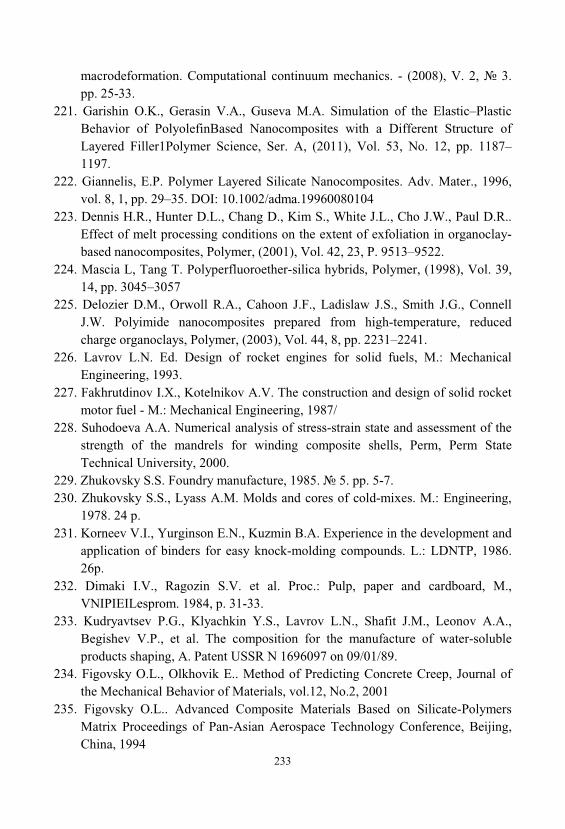
233
macrodeformation. Computational continuum mechanics. - (2008), V. 2, 3. pp. 25-33.
221. Garishin O.K., Gerasin V.A., Guseva M.A. Simulation of the Elastic–PlasticBehavior of PolyolefinBased Nanocomposites with a Different Structure ofLayered Filler1Polymer Science, Ser. A, (2011), Vol. 53, No. 12, pp. 1187–1197.
222. Giannelis, E.P. Polymer Layered Silicate Nanocomposites. Adv. Mater., 1996, vol. 8, 1, pp. 29–35. DOI: 10.1002/adma.19960080104
223. Dennis H.R., Hunter D.L., Chang D., Kim S., White J.L., Cho J.W., Paul D.R.. Effect of melt processing conditions on the extent of exfoliation in organoclay-based nanocomposites, Polymer, (2001), Vol. 42, 23, P. 9513–9522.
224. Mascia L, Tang T. Polyperfluoroether-silica hybrids, Polymer, (1998), Vol. 39, 14, pp. 3045–3057
225. Delozier D.M., Orwoll R.A., Cahoon J.F., Ladislaw J.S., Smith J.G., ConnellJ.W. Polyimide nanocomposites prepared from high-temperature, reducedcharge organoclays, Polymer, (2003), Vol. 44, 8, pp. 2231–2241.
226. Lavrov L.N. Ed. Design of rocket engines for solid fuels, M.: MechanicalEngineering, 1993.
227. Fakhrutdinov I.X., Kotelnikov A.V. The construction and design of solid rocketmotor fuel - M.: Mechanical Engineering, 1987/
228. Suhodoeva A.A. Numerical analysis of stress-strain state and assessment of thestrength of the mandrels for winding composite shells, Perm, Perm StateTechnical University, 2000.
229. Zhukovsky S.S. Foundry manufacture, 1985. 5. pp. 5-7. 230. Zhukovsky S.S., Lyass A.M. Molds and cores of cold-mixes. M.: Engineering,
1978. 24 p. 231. Korneev V.I., Yurginson E.N., Kuzmin B.A. Experience in the development and
application of binders for easy knock-molding compounds. L.: LDNTP, 1986. 26p.
232. Dimaki I.V., Ragozin S.V. et al. Proc.: Pulp, paper and cardboard, M., VNIPIEILesprom. 1984, p. 31-33.
233. Kudryavtsev P.G., Klyachkin Y.S., Lavrov L.N., Shafit J.M., Leonov A.A., Begishev V.P., et al. The composition for the manufacture of water-solubleproducts shaping, A. Patent USSR N 1696097 on 09/01/89.
234. Figovsky O.L., Olkhovik E.. Method of Predicting Concrete Creep, Journal ofthe Mechanical Behavior of Materials, vol.12, No.2, 2001
235. Figovsky O.L.. Advanced Composite Materials Based on Silicate-PolymersMatrix Proceedings of Pan-Asian Aerospace Technology Conference, Beijing, China, 1994
234
236. Geguzin A.J. Physics of sintering, M.: Nauka, 1984, 312 p. 237. Solomatov V.I, Boryshev A.N, Himmler N.G. Polymer composite materials in
construction. M., Stroyizdat, 1988. 238. Figovsky O., Beilin D. Improvement of Strength and Chemical Resistance of
Silicate Polymer Concrete. International Journal of Concrete Structures andMaterials. 2009, vol. 3, no. 2, pp. 97—101. DOI: 10.4334/IJCSM.2009.3.2.097.
239. Barbakadze V.S., Kozlov V.V., Mikul’skii V.G., Nikolov I.I. Durability ofBuilding Structures and Constructions from Composite Materials. Science, 1995, 264 p.
240. Karchevsky V., Figovsky O., Romm F. Polymeric composition having self-extinguishing properties. US Patent Demand N. 035/99 USA, positive decision(grant) of 10.9.01.
241. Karchevsky V., Romm F., Figovsky O., Boot A., Axenov O., Fiskin Z. Conductive composition having self- extinguishing properties. U.S. Patentdemand N. 064/99 USA, positive decision of 15.4.01.
242. Romm F., Karchevsky V, Axenov O, Potashnikov R., Figovsky O.L.. CoatingsBased on Quarternary Ammonium Silicates: Preparation, Properties andApplication Scientific Israel - Technological Advantages, Vol. 4, No. 4, pp. 75-81
243. Romm F., Karchevsky V., Figovsky O.L. Optimal Fire Tests of ProtectiveCoatings Materials Performance No1, 2002, pp.44-47
244. Figovsky O.L., Karchevsky V., Beilin D. Advanced Fire - Protective WoodCoatings, Scientific Israel - Technological Advantages, 2002,Vol. 4, No. 4, pp. 94-97
245. Vazhenin E.V., Kruchilina L.P., Veprev G.I., Naboko VM, Tikhonov R.D., Artemyev V.M. Patent USSR 783290, composition for the manufacture of heat-insulating material. Request: 2671608, 10.10.1978, Published: 30/11/1980 at BI, N 44 MKI C04B43 / 02
246. Arkhipov V.V., Podkopaev V.I. Heat-resistant fiber boards on the silica sol, Proc.; Building materials and products on the basis of industrial wastes. Chelyabinsk Uralniistromproekt, 1987, p. 176.
247. A study of strength and patterns of change in the mechanical properties of newcomposite and refractory materials in a wide range of temperatures and loadingrates based on structural and technological and other factors affecting operationof real products. N state. Registration 79007301, Kiev, 1982, Vol. 3 89.
248. Kudryavtsev P.G., Kavalerova O.B., Kazakova I.L., Zharnylskaya A.L., VolkhinV.V. Silica and aluminum-sols as binders in the sol-gel technology forproduction of composite materials, Moscow Interregional Conference onComposites, 1990, p.112.
235
249. Physical and chemical bases of synthesis of oxide and silicate materials"Proceedings MChTI them. Mendeleev, M, vol. 146, 1987.
250. Qi-Ming Yuan, Jia-Qi Tan. Processing and Microstrukture of Mullite—ZirkoniaComposites Prepared from Sol—Gel Powders., J. Amer. Ceram. Soc., 1986, V69, N 3, p. 268-269.
251. Vorontsov E.S. Mechanism and kinetics of topochemical reactions taking placewith decrease in the volume of the solid phases, Russ. Chem. Rev., 1965, vol. 34, 11, 883–892.
252. Adachi ., Sakka S. The role of N,N-dimethylformamide, a DCCA, in theformation of silica gel monoliths by sol-gel method, J. of Non-CrystallineSolids, 1988, V.99. P.118-128.
253. Buckley X.D. Stronhal ., Sansler I.I. Ceramic Bull., 1981, 60, N 11, . 1196-1199.
254. Volkhin V.V., Egorov Yu.I., Belinskaya F.A., Boychinova E.S., Malofeeva G.I., Inorganic sorbents. Proc.: Ion exchange, M.: Science, 1981, pp. 25-44.
255. Kudryavtsev P.G., Kavalerova O.B., Volkhin V.V. Preparation of monolithicblocks based on the silica sol with organic additives, Proc. Scien. works. Sol-gelprocesses for the production of inorganic materials. Ural Branch of the RussianAcademy of Sciences, 1996, p. 87-91.
256. Adachi ., Sakka S. Sintering of silica gel derived from the alkoxysilanesolution containing N,N-dimethylformamide // J. of Non-Crystalline Solids, 1988. V. 100. P.250–253.
257. Hench L.L. Use of drying control chemical additives (DCCA) in controlling sol-gel processing, Ceram. Chem. Process.: Proc. Int. Conf. Ultrastruct. 1985,
258. Anderson P., Klein L.C. Shrinkage of lithium aluminosilicate gels during drying, J. of Non-Crystalline Solids, 1987. v. 93. P. 415-422.
259. Kudryavtsev P.G., Kavalerova O.B., Volkhin V.V. Preparation of monolithicblocks based on the silica sol with organic additives Seminar sol-gel processesfor the production of inorganic materials, Perm, 1991, p.32.
260. Figovsky O.L., Beylin D.A. Nanostructured Silicate Polymer Concrete. VestnikMGSU 2014, N 3, pp. 197—204.
261. Iler R.K. Adsorption of Colloidal Silica on Alumina and of Colloidal Aluminaon Silica. Journal of the American Ceramic Society, 1964, vol. 47: 194–198. DOI: 10.1111/j.1151-2916.1964.tb14391.x
262. Yirgensons ., Straumanis M. E. Colloid Chemistry, Mcmillan., New York, 1962, p. 101-132.
263. Iler R.K. Multilayers of colloidal particles, Journal of Colloid and InterfaceScience, Vol. 21, 6, 1966, pp. 569–594, DOI: 10.1016/0095-8522(66)90018-3.
236
264. Visser. 49th National colloid Symposium, Clarson College of Fechology, Potsdam, 1979, N 7.
265. Qutowski W. Inz. Chem., 1973, V 3, N 3, , p. 477. 266. Davies R., Ranade M.B, 49th National Colloid Symposium., Clarson College of
Fechaclogy, Potsdam, N 7, 1975. 267. Kudryavtsev P.G., Pilipenko V.G., Vorobyev O.A., Krotkich A.N., Kavalerova
O.B. The application of silica sols and aluminum for ultralegkovesnyh shieldingmaterials, Seminar: The sol-gel processes for the production of inorganicmaterials, Perm, 1991, p.62.
268. Kudryavtsev P.G., Kropacheva M.V., Kavalerova O.B., Pilipenko V.G., Vorobyev O.A., Kazakova I.L. The use of sol-gel processes for ultra-lightweightcomposite materials, composite materials based on dispersed systems, Perm, 1991, p.19-23.
269. Kudryavtsev P.G. Methods of preparation of oxide lightweight refractorymaterials, Proc. Scien. works. Composite materials based on dispersed systems, Ekaterinburg, Ural Branch of Russian Academy of Sciences, 1994, p. 4-21.
270. Kruchinina L.P., Vazhenin E.V. Efficient high-alumina binder fibers, Non-Ferrous Metals, 1981, N 9, p. 51-53.
271. Physical chemistry of silicates. / Ed. Pashchenko A.A., M.: Higher School, 1986, 368 p.
272. Kudryavtsev P.G., Kropacheva M.V. Getting ultralegkovesnyh ceramicmaterials using the sol-gel transition, Proc. Conf.: Physico-chemical basis ofpoor processing of natural raw materials and industrial waste in the preparationof heat-resistant materials, Syktyvkar, V. 1, 1989, p. 73.
273. Kudryavtsev P.G., Kropacheva M.V., Kavalerova O.B., Pilipenko V.G., Vorobyev O.A., Volkhin V.V. The sol-gel method for obtaining ultra-lightweight refractory composite materials, Moscow Interregional Conferenceon Composites, 1990, p.127.
274. Kudryavtsev P.G., Kavalerova O.B., Pilipenko V.G., Kazakov I.L., VorobievO.A., Kropacheva M.V. A method for producing refractory TPM, Patent USSRN 1787890, by request from 08.01.91 4900496/33, publ. BI 2 on 15/01/93
275. http://phys.org/news184310039.html276. Di Salvo, S., Nanotechnology for cultural heritage, International Journal of
Science, Technology and Society, 2014; 2(2), pp. 28-32, doi:10.11648/j.ijsts.20140202.12
277. Di Salvo S., Patent Pending PA2011A000012278. Di Salvo, S., Methodological approaches for the enhancement of cultural
heritage, Aracne, Rome, 2012.
237
279. Guyomard-Lack A., Abusleme J., Soudan P., Lestriez B., Guyomard D., LeBideau J. Hybrid Silica–Polymer Ionogel Solid Electrolyte with TunableProperties, Adv. Energy Mater. 2014, 4, 1301570
280. Pathak S. K., Abate A., Leijtens T., Hollman D.J., Teuscher J., Pazos L., Docampo P., Steiner U., Snaith H.J. Towards Long-Term Photostability ofSolid-State Dye Sensitized Solar Cells, Adv. Energy Mater. 2014, 4, 1301667
281. Spange S., Grund S. Nanostructured organic-inorganic composite materials bytwin polymerization of hybrid monomers. Adv Mater, Weinheim, Ger, (2009), Vol. 21, 20, pp. 2111–2116. doi: 10.1002/adma.200802797
282. Novak, B.M. Hybrid Nanocomposite Materials—between inorganic glasses andorganic polymers. Adv. Mater., (1993), 5: 422–433. doi:10.1002/adma.19930050603
283. Lower N.P., Boone A.P., Wilcoxon R.K. US patent 8,637,890. Adhesiveapplications using alkali silicate glass for electronics, (2014).
284. Onozawa et al. US patent 8,507,630. Organic inorganic composite material andutilization thereof, (2013).
285. Kuchumov B.M., Koretskaya T.P., Igumenov I.K., Zharkova G.I., SebezhkoV.N. A method of applying a metallic coating on a substrate, RF Patent2392352 from 26.11.2008.
286. Moitra N., Ichii S., Kamei T., Kanamori K., Zhu Y., Takeda K., Nakanishi K., and Shimada T. Surface Functionalization of Silica by Si–H Activation ofHydrosilanes, Journal of the American Chemical Society, (2014), Vol. 136, 33, pp. 11570-11573, DOI: 10.1021/ja504115d.
287. Delozier D.M., Orwoll R.A., Cahoon J.F., Ladislaw J.S., Smith J.G., ConnellJ.W. Polyimide nanocomposites prepared from high-temperature, reducedcharge organoclays, Polymer, (2003), Vol. 44, 8, pp. 2231–2241.
288. Armstrong R.W., Coffey C.S., DeVost V.F., Elban W.L. Crystal sizedependences for the impact initiation of cyclotrimethylenetrimitramineexplosive. J. Appl. Phys., (1990), 68, pp. 979–984.
289. Levitsky M.M., Zavin B.G., Bilyachenko A.N. The Chemistry of MetalOrganosiloxanes. Current Trends of Develjpmeny and Concepts, RussianChemical Reviews, 76, (9), 2007, pp.907-926.
290. Coates G.E., Aylett B.I., Green L.H.. Organometallic Compounds. Groups IVand V. Chapman and Hall, London, 1979.
291. Zhdanov A.A., Levitsky M.M. The book: Advances in the synthesis oforganometallic polymers. (Ed. V.V. Korshak). Nauka, Moscow, 1988. p. 143.
292. Andrianov K.A., Khananashvili L.M. Technology organometallic monomersand polymers. Chemistry, Moscow, 1973
293. Sugama T., Carciello N., Rast S.L.. Thin Solid Films, 258, 174 (1995)
238
294. Sobota P., Przybylak S., Ejfler J., Kobylka M., Jerzykiewicz L.B.. Inorg. Chim. Acta, 334, 159 (2002)
295. Beckmann J., Jurkschat K. Coord. Chem. Rev., 215, 267 (2001)296. Gosink H.J., Roesky H.W., Noltemeyer M., Schmidt H.G., Freire-Erdbrugger
C., Sheldrick G.M. Chem. Ber., 126, 279 (1993)297. Voigt A., Murugavel R., Roesky H.W., Schmidt H.G. J. Mol. Struct., 437, 49
(1997)298. Sydora O.L., Wolczanski P.T., Lobkovsky E.B., Buda C., Cundari T.R. Inorg.
Chem., 44, 2606 (2005)299. Rosenfeld D.C., Kuiper D.S., Lobkovsky E.B., Wolczanski P.T. Polyhedron, 25, 251 (2006)300. Levitsky M.M., Shchegolikhina O.I., Zhdanov A.A., Igonin V.A., Ovchinnikov
Yu.E., Shklover V.E., Struchkov Yu.T.. J. Organomet. Chem., 401, 199(1991)301. Borisov Yu.A., Papkov V.S., Rabkina A.Yu., Zavin B.G.. J. Mol. Struct.
(THEOCHEM), 664 - 665, 157 (2003)302. Kapustina A., Shapkin N.P., Gavrilova N., Kalugin M.Y., Bessonova V.I.
Journal of General Chemistry, 70, 258 (2000)303. Kruger R.P., Much H., Schulz G., Rikowski E. Monatsh. Chem., 130, 163
(1999)304. Wichmann D., Jug K.. J. Phys. Chem. B, 103, 10087 (1999)305. Jug K., Wichmann D. J. Comput. Chem., 16, 1549 (2000)306. Greiser T., Jarchow O., Klaska K.-H., Weiss E. Chem. Ber., 111, 3360 (1978)307. Sletteri J., Theory of transfer of momentum, energy and mass in continuous
media, M., Mir, 1978. 308. Heifetz L.I., Neumark A.V., Multiphase processes in porous media, M., 1982. 309. Frank-Kamenetsky D.A., Diffusion and Heat Transfer in Chemical Kinetics, 3rd
ed., M., 1987. 310. Heifetz L.I., Bruno E.B., Theoretical Foundations of Chemical Engineering,
1987, vol. 21, 2, p. 191-214. 311. Merzhanov A.G., Rumanov E.N., Advances of Physical Sciences, 1987, Vol.
151, 4, pp. 553-593. 312. Flory, P.J. Statistical Mechanics of Chain Molecules. Interscience, New York,
1969. 313. Moshinsky, L. and Figovsky, O. Proc. Intern. Conf. “Corrosion in Natural and
Industrial Environments: Problems and Solutions”, 1995, 699. 314. Romm, F. Evaluation of the weight distribution of polymers from reversible
polymerization, using a statistical polymer method, J. Phys. Chem., 1994, 98(22), pp. 5765–5767, DOI: 10.1021/j100073a032
239
315. Gontar, V. New theoretical approach for physicochemical reactions dynamicswith chaotic behaviour. In Chaos in Chemistry and Biochemistry, WorldScientific, London, 1993, pp. 225-247.
316. Smoluchowski M.V. Zs. Phys. Chem. V. 92, p. 129 (1917). 317. Schuman T.E.W., Qnart. Yourn. R. Met. Soc. V. 66, p. 195 (1940). 318. Ziff R.M., G. Stell Kinetics of polymer gelation. J. Chem. Phys. V 73, N7, p.
3492, (1980). 319. Vinokourov L.I., Kats A.V. Power solutions of the kinetic equation for fixed
aerosol coagulation. Izvestiya Academy of Sciences of the USSR. Physics of theatmosphere and ocean. 1980, Vol. 16, N6, pp. 601 – 607.
320. Stockmayer W.H.Y. Chem. Phys. V. 11.45 (1943). 321. White W.H.Y. Colloid Interface Sci, V. 87, p. 204 (1982). 322. Lushnikov A.A. Some new aspects of the theory of coagulation. Izvestiya
Academy of Sciences of the USSR. Physics of the atmosphere and ocean. 1978, Vol. 14, N10, pp. 1046 – 1054.
323. Domilovsky E.R., Lushnikov A.A., Piskunov V.N. Modeling of coagulationprocess Monte Carlo. DAN, 1978, Vol. 240, N 1, p. 108 - 110.
324. Zhyulne R. Fractal aggregates, UFN, 1989, Vol. 157, N 2, . 339 – 357. 325. Smirnov B.M. Properties of fractal aggregate, UFN, 1989, Vol. 157, N 2, p. 357
- 360. 326. Lifshitz, EM, Pitaevskii, LP Statistical physics. Part 2. The theory of the
condensed state. ("Theoretical Physics", Vol IX). - M.: FIZMATLIT, 2004. -496 p.
327. Levenshpil O. Engineering design of chemical processes, Chemistry, 1969328. Dorohov I.N., Kafarov V.V. Systematic analysis of the processes of chemical
technology. Nauka, Moscow, 1989, 376 p. 329. Morachevsky A.P. Physical chemistry - surface phenomena and disperse
systems - SPb., 2011330. Bondarev B.V., Kalashnikov N.P., Spirin G.G. General physics course: in 3
books. Book 3. Statistical physics. Structure of Matter. M.: Yurayt, 2013, 369 p. 331. Smirnov B.M. Aerogels, Advances in physical Sciences, Vol. 152, 1, 1987,
pp.133-157. 332. Holtje H.-D., Sippl W., Rognan D., Folkers G., Molecular Modeling. Basic
Principles and Applications. WILEY-VCH Verlag GmbH & Co. KGaA, (2008), 318 p.
333. Andre, R., Tahir, M. N., Natalio, F. and Tremel, W. Bioinspired synthesis ofmultifunctional inorganic and bio-organic hybrid materials. FEBS Journal, (2012), p.279: 1737–1749. doi: 10.1111/j.1742-4658.2012.08584.x
240
334. Rob W.M. Van Soest, Boury-Esnault N., Vacelet J., Dohrmann M., ErpenbeckD., De Voogd N.J., Santodomingo N., et al. Global Diversity of Sponges(Porifera). PLoS ONE 7(4), 2012, e35105. doi:10.1371/journal.pone.0035105
335. Bauerlein E., Behrens P. & Epple M. Handbook of Biomineralization, 1st edn. Wiley-VCH, Weinheim. (2007).
336. Mann S., Archibald D.D., Didymus J.M., Douglas T., Heywood B.R., MeldrumF.C. & Reeves N.J. Crystallization at inorganic–organic interfaces: biomineralsand biomimetic synthesis. Science 261, (1993), pp. 1286–1292.
337. Lakes R.S. Materials with structural hierarchy. Nature, 361, (1993), pp. 511–515.
338. Douglas T. A bright bio-inspired future. Science, 299, (2003), pp.1192–1193. 339. Shimizu K., Cha J., Stucky G.D. & Morse D.E. Silicatein- : cathepsin L-like
protein in sponge biosilica.Proc Natl Acad Sci USA 95, (1998), pp. 6234–6238. 340. Brutchey R.L. & Morse D.E. Silicatein and the translation of its molecular
mechanism of biosilicification into low temperature nanomaterial synthesis. Chem Rev 108, (2008), pp.4915–4934.
341. Wetherbee R. The diatom glasshouse. Science 298, (2002), p.547. 342. Schroder H.C., Wang X., Tremel W., Ushijima H. & Muller W.E.G.
Biofabrication of biosilica-glass by living organisms. Nat Prod Rep 25, (2008), pp. 455–474.
343. Lux A., Luxova M., Morita S., Abe J. & Inanaga S. Endodermal silicification indeveloping seminal roots of lowland and upland cultivars of rice (Oryza sativaL). Can J Bot 77, (1999), pp. 955–960.
344. Kroger N. & Poulsen N. Diatoms – from cell wall biogenesis to nanotechnology. Annu Rev Genet 42, (2008), pp. 83–107.
345. Aizenberg J., Weaver J.C., Thanawala M.S., Sundar V.C., Morse D.E. & FratzlP. Skeleton of Euplectella sp.: structural hierarchy from the nanoscale to themacroscale. Science 309, (2005), pp. 275–278.
346. Dickerson M.B., Sandhage K.H. & Naik R.R. Protein- and peptide-directedsyntheses of inorganic materials. Chem Rev 108, (2008), pp. 4935–4978.
347. Wolf S.E., Schloßmacher U., Pietuch A., Mathiasch B., Schroder H.C., MullerW.E.G. & Tremel W. Formation of silicones mediated by sponge enzymesilicateina. Dalton Trans 39, (2010), pp. 9245–9249.
348. Tahir M.N., The´ato P., Muller W.E.G., Schroder H.C., Boreijko A., Faiß S., Janshoff A., Huth J. & Tremel W. Formation of layered titania and zirconiacatalyzed by surface-bound silicatein. Chem Commun 28, (2005), pp. 5533–5535.
241
349. Ould-Ely T., Luger M., Kaplan-Reinig L., Niesz K., Doherty M. & Morse D.E. Large-scale engineered synthesis of BaTiO3 nanoparticles using low-temperature bioinspired principles. Nat Protoc 6, (2011), pp. 97–104.
350. Kisailus D., Choi J.H., Weaver J.C., Yang W. & Morse D.E. Enzymaticsynthesis and nanostructural control of gallium oxide at low temperature. AdvMater 17, (2005), pp.314–318.
351. Cha J.N., Stucky G.A., Morse D..E & Deming T.E. Biomimetic synthesis ofordered silica structures by block copolypeptides. Nature 403, (2000), pp. 289–292.
352. Pinkos R. Aluminum alkoxides, Russ. Chem. Rev., 37, 4, (1968), p.647-676.