Embed Size (px)
Citation preview
Type XPI-III Surge ArrestersMaximum System Voltage 2 to 48 kV
2 XPI-III Metal Oxide Surge Arresters
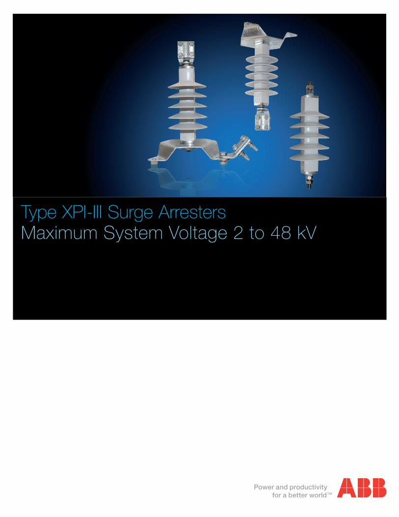
XPI-III Metal Oxide Surge Arresters are for protection of switchgear, transformers, and other equipment in high voltage systems against lightning and switching overvoltages. For use when requirements of lightning intensity, energy capability and pollution are moderate.
Superior design where low weight, reduced clearances, flexible mounting, and shatter-proof housing is required.
ApplicationThe XPI-III polymer arrester has been verified to meet or exceed all intermediate class requirements of ANSI C62.11 (IEEE Standard for Metal-Oxide Surge Arresters for AC Power Circuits) and Line Discharge Class 1 requirements of IEC 600099-4 (IEC Standard for Metal-Oxide Surge Arresters without gaps for AC Systems). The XPI-III arrester is designed to meet the following performance data.
Performance dataMaximum system voltages (Vm) 2.52 - 48.3 kV rms
Duty cycle rated voltages (Vr) 3 - 45 kV rms
Classifying current (ANSI/IEEE) 10 kA peak
Discharge current withstand strength: High current 4/10 µs 100 kA peak Low current 2000 µs 250 A peak
Energy capability: 2 impulses, (IEC Cl. 7.5.5) 3.6 kJ / kV of MCOV Fulfills requirements of ANSI transmission-line discharge test for 36.2 kV systems
Short-circuit / pressure relief capability 20 kA rms sym Cantilever strength 2200 in - lbs / 250 Nm
Service conditions: Ambient temperature -40 °C to +45 °C Design altitude 6000 ft / 1830 m Frequency 15 - 62 Hz
Note: Higher altitudes designs available on request
XPI-III Metal Oxide Surge Arrester
XPI-III Metal Oxide Surge Arresters 3
Benefits
Direct-molded constructionABB’s type XPI-III surge arrester consists of high performance metal oxide disks molded in a shatter-proof polymer housing. The XPI-III now has a new construction to enhance overall lifetime performance.
The metal oxide disks are enclosed in a support assembly consisting of reinforced epoxy / fiberglass loops connecting the upper and lower aluminum end pieces. The silicone polymer material is then molded directly to the metal oxide loop assembly eliminating any air pockets which could cause moisture ingress over time.
Each arrester is furnished with a mounting base for an 8.75 in / 222 mm diameter bolt circle along with 4-hole, line and ground terminals for electrical connections.
100% silicone based housingThe silicone rubber housing features high tracking and arc resistance, excellent hydrophobic properties, and resistance to weathering, UV radiation and pollution.
The incorporation of polymer material in an intermediate class arrester has resulted in many additional advantages. Among these are:
Direct-molded construction ABB’s XPI-III Surge Arrester consists of high performance metal oxide disks molded in a shatter-proof polymer housing. The XPI-III Surge Arrester now has a new construction to enhance overall lifetime performance.
The metal oxide disks are enclosed in a support assembly consisting of reinforced epoxy/fiberglass loops connecting the upper and lower aluminum end pieces. The silicone polymer material is then molded directly to the metal oxide loop assembly eliminating any air pockets which could cause moisture ingress over time.
Reduced electrical clearance Polymer construction has resulted in much smaller housing dimensions in comparison with porcelain units of the same voltage rating. This size reduction enables efficient use of space for switchgear enclosures, mobile substations and other applications where space restrictions are present.
Lightweight The XPI-III Surge Arrester is less than 50 percent the weight of its porcelain counterpart, which results in easier handling and installation.
Damage resistant Polymer construction reduces possible shipping and handling damage, as well as, damage due to vandalism.
Safety Shatter-resistant construction provides greater protection for personnel, as well as, nearby equipment.
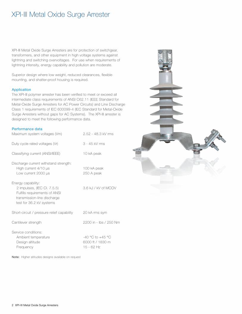
Drilling plan
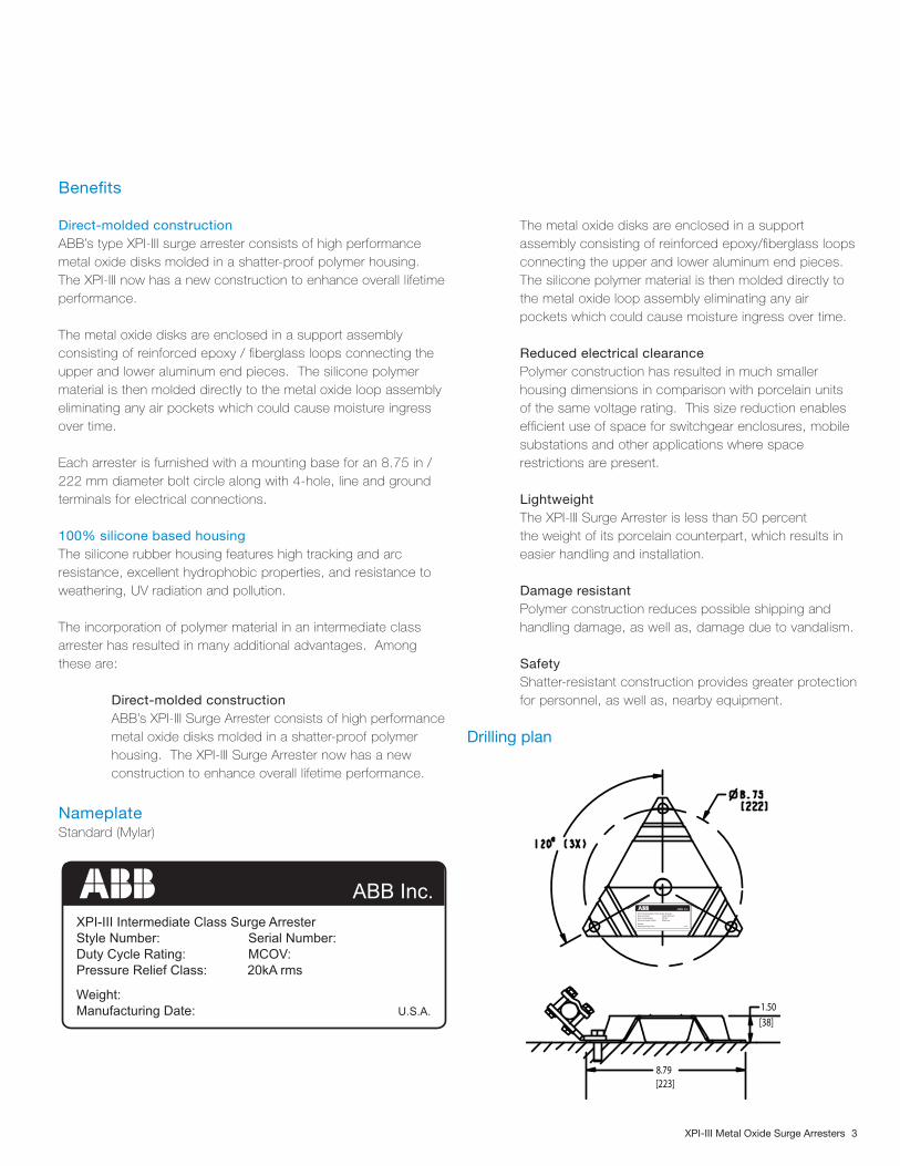
NameplateStandard (Mylar)
XPI-III Intermediate Class Surge ArresterStyle Number: Serial Number:Duty Cycle Rating: MCOV:Pressure Relief Class: 20kA rms
Weight:Manufacturing Date: U.S.A.
ABB Inc.
1.50[38]
8.79[223]
XPI-III Intermediate Class Surge ArresterStyle Number: Serial Number:Duty Cycle Rating: MCOV:Pressure Relief Class: 20kA rms
Weight:Manufacturing Date: U.S.A.
ABB Inc.
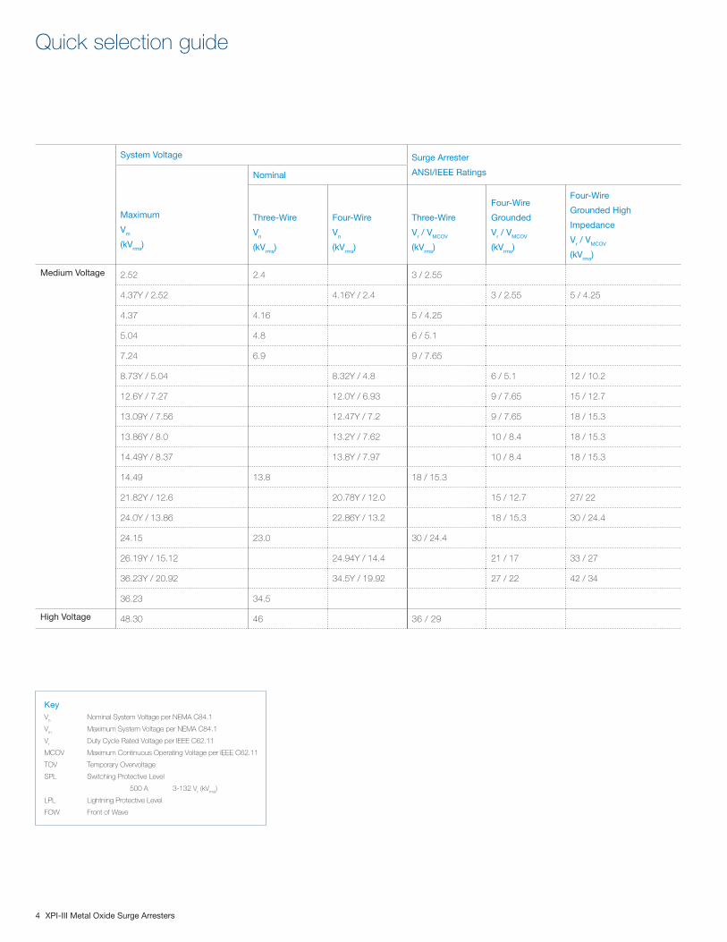
Quick selection guide
4 XPI-III Metal Oxide Surge Arresters
System Voltage Surge Arrester
ANSI/IEEE Ratings
Maximum
Vm
(kVrms)
Nominal
Three-Wire
Vn
(kVrms)
Four-Wire
Vn
(kVrms)
Three-Wire
Vr / VMCOV
(kVrms)
Four-Wire
Grounded
Vr / VMCOV
(kVrms)
Four-Wire
Grounded High
Impedance
Vr / VMCOV
(kVrms)
Medium Voltage 2.52 2.4 3 / 2.55
4.37Y / 2.52 4.16Y / 2.4 3 / 2.55 5 / 4.25
4.37 4.16 5 / 4.25
5.04 4.8 6 / 5.1
7.24 6.9 9 / 7.65
8.73Y / 5.04 8.32Y / 4.8 6 / 5.1 12 / 10.2
12.6Y / 7.27 12.0Y / 6.93 9 / 7.65 15 / 12.7
13.09Y / 7.56 12.47Y / 7.2 9 / 7.65 18 / 15.3
13.86Y / 8.0 13.2Y / 7.62 10 / 8.4 18 / 15.3
14.49Y / 8.37 13.8Y / 7.97 10 / 8.4 18 / 15.3
14.49 13.8 18 / 15.3
21.82Y / 12.6 20.78Y / 12.0 15 / 12.7 27/ 22
24.0Y / 13.86 22.86Y / 13.2 18 / 15.3 30 / 24.4
24.15 23.0 30 / 24.4
26.19Y / 15.12 24.94Y / 14.4 21 / 17 33 / 27
36.23Y / 20.92 34.5Y / 19.92 27 / 22 42 / 34
36.23 34.5
High Voltage 48.30 46 36 / 29
KeyV
n Nominal System Voltage per NEMA C84.1
Vm Maximum System Voltage per NEMA C84.1
Vr Duty Cycle Rated Voltage per IEEE C62.11
MCOV Maximum Continuous Operating Voltage per IEEE C62.11
TOV Temporary Overvoltage
SPL Switching Protective Level
500 A 3-132 Vr (kV
rms)
LPL Lightning Protective Level
FOW Front of Wave
XPI-III Metal Oxide Surge Arresters 5
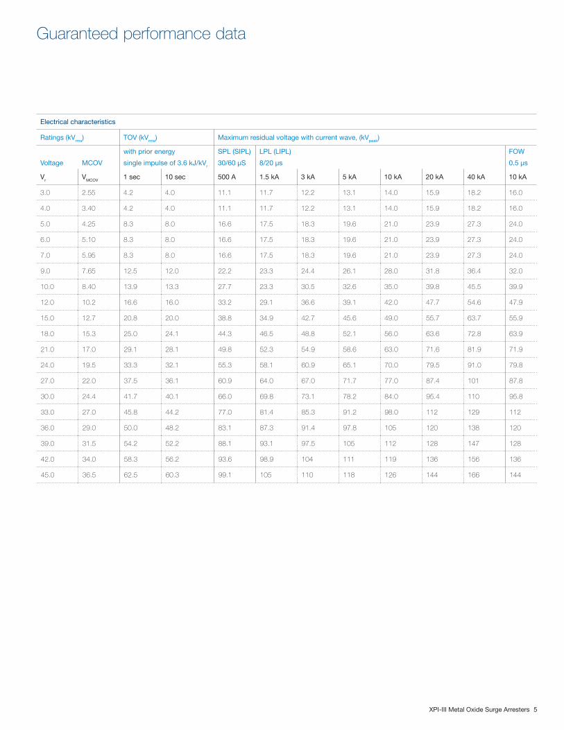
Electrical characteristics
Ratings (kVrms) TOV (kVrms) Maximum residual voltage with current wave, (kVpeak)
Voltage MCOV
with prior energy
single impulse of 3.6 kJ/kVr
SPL (SIPL)
30/60 µS
LPL (LIPL)
8/20 µs
FOW
0.5 µs
Vr VMCOV 1 sec 10 sec 500 A 1.5 kA 3 kA 5 kA 10 kA 20 kA 40 kA 10 kA
3.0 2.55 4.2 4.0 11.1 11.7 12.2 13.1 14.0 15.9 18.2 16.0
4.0 3.40 4.2 4.0 11.1 11.7 12.2 13.1 14.0 15.9 18.2 16.0
5.0 4.25 8.3 8.0 16.6 17.5 18.3 19.6 21.0 23.9 27.3 24.0
6.0 5.10 8.3 8.0 16.6 17.5 18.3 19.6 21.0 23.9 27.3 24.0
7.0 5.95 8.3 8.0 16.6 17.5 18.3 19.6 21.0 23.9 27.3 24.0
9.0 7.65 12.5 12.0 22.2 23.3 24.4 26.1 28.0 31.8 36.4 32.0
10.0 8.40 13.9 13.3 27.7 23.3 30.5 32.6 35.0 39.8 45.5 39.9
12.0 10.2 16.6 16.0 33.2 29.1 36.6 39.1 42.0 47.7 54.6 47.9
15.0 12.7 20.8 20.0 38.8 34.9 42.7 45.6 49.0 55.7 63.7 55.9
18.0 15.3 25.0 24.1 44.3 46.5 48.8 52.1 56.0 63.6 72.8 63.9
21.0 17.0 29.1 28.1 49.8 52.3 54.9 58.6 63.0 71.6 81.9 71.9
24.0 19.5 33.3 32.1 55.3 58.1 60.9 65.1 70.0 79.5 91.0 79.8
27.0 22.0 37.5 36.1 60.9 64.0 67.0 71.7 77.0 87.4 101 87.8
30.0 24.4 41.7 40.1 66.0 69.8 73.1 78.2 84.0 95.4 110 95.8
33.0 27.0 45.8 44.2 77.0 81.4 85.3 91.2 98.0 112 129 112
36.0 29.0 50.0 48.2 83.1 87.3 91.4 97.8 105 120 138 120
39.0 31.5 54.2 52.2 88.1 93.1 97.5 105 112 128 147 128
42.0 34.0 58.3 56.2 93.6 98.9 104 111 119 136 156 136
45.0 36.5 62.5 60.3 99.1 105 110 118 126 144 166 144
Guaranteed performance data
6 XPI-III Metal Oxide Surge Arresters
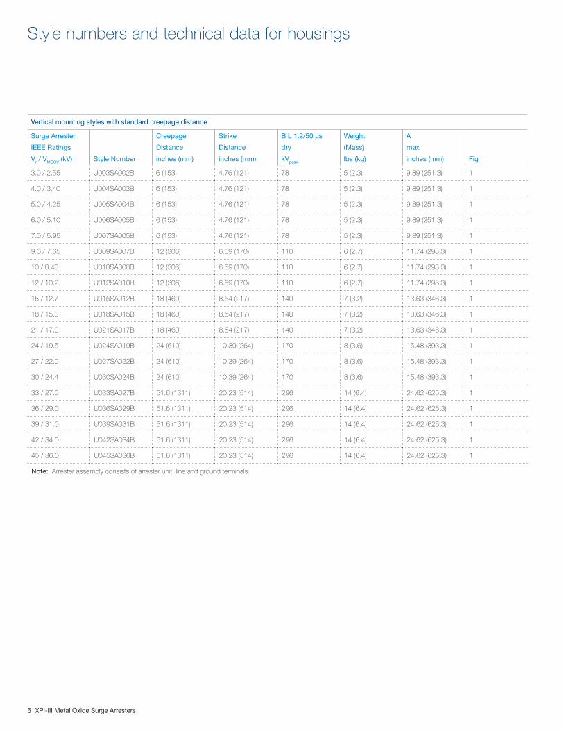
Style numbers and technical data for housings
Vertical mounting styles with standard creepage distance
Surge Arrester
IEEE Ratings
Vr / VMCOV (kV) Style Number
Creepage
Distance
inches (mm)
Strike
Distance
inches (mm)
BIL 1.2/50 µs
dry
kVpeak
Weight
(Mass)
lbs (kg)
A
max
inches (mm) Fig
3.0 / 2.55 U003SA002B 6 (153) 4.76 (121) 78 5 (2.3) 9.89 (251.3) 1
4.0 / 3.40 U004SA003B 6 (153) 4.76 (121) 78 5 (2.3) 9.89 (251.3) 1
5.0 / 4.25 U005SA004B 6 (153) 4.76 (121) 78 5 (2.3) 9.89 (251.3) 1
6.0 / 5.10 U006SA005B 6 (153) 4.76 (121) 78 5 (2.3) 9.89 (251.3) 1
7.0 / 5.95 U007SA005B 6 (153) 4.76 (121) 78 5 (2.3) 9.89 (251.3) 1
9.0 / 7.65 U009SA007B 12 (306) 6.69 (170) 110 6 (2.7) 11.74 (298.3) 1
10 / 8.40 U010SA008B 12 (306) 6.69 (170) 110 6 (2.7) 11.74 (298.3) 1
12 / 10.2. U012SA010B 12 (306) 6.69 (170) 110 6 (2.7) 11.74 (298.3) 1
15 / 12.7 U015SA012B 18 (460) 8.54 (217) 140 7 (3.2) 13.63 (346.3) 1
18 / 15.3 U018SA015B 18 (460) 8.54 (217) 140 7 (3.2) 13.63 (346.3) 1
21 / 17.0 U021SA017B 18 (460) 8.54 (217) 140 7 (3.2) 13.63 (346.3) 1
24 / 19.5 U024SA019B 24 (610) 10.39 (264) 170 8 (3.6) 15.48 (393.3) 1
27 / 22.0 U027SA022B 24 (610) 10.39 (264) 170 8 (3.6) 15.48 (393.3) 1
30 / 24.4 U030SA024B 24 (610) 10.39 (264) 170 8 (3.6) 15.48 (393.3) 1
33 / 27.0 U033SA027B 51.6 (1311) 20.23 (514) 296 14 (6.4) 24.62 (625.3) 1
36 / 29.0 U036SA029B 51.6 (1311) 20.23 (514) 296 14 (6.4) 24.62 (625.3) 1
39 / 31.0 U039SA031B 51.6 (1311) 20.23 (514) 296 14 (6.4) 24.62 (625.3) 1
42 / 34.0 U042SA034B 51.6 (1311) 20.23 (514) 296 14 (6.4) 24.62 (625.3) 1
45 / 36.0 U045SA036B 51.6 (1311) 20.23 (514) 296 14 (6.4) 24.62 (625.3) 1
Note: Arrester assembly consists of arrester unit, line and ground terminals
XPI-III Metal Oxide Surge Arresters 7
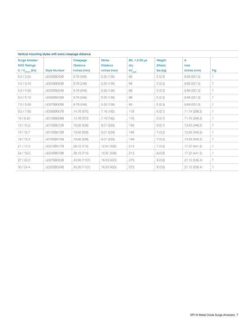
Vertical mounting styles with extra creepage distance
Surge Arrester
IEEE Ratings
Vr / VMCOV (kV) Style Number
Creepage
Distance
inches (mm)
Strike
Distance
inches (mm)
BIL 1.2/50 µs
dry
kVpeak
Weight
(Mass)
lbs (kg)
A
max
inches (mm) Fig
3.0 / 2.55 U003SB002B 9.76 (248) 5.35 (136) 88 5 (2.3) 9.89 (251.3) 1
4.0 / 3.40 U004SB003B 9.76 (248) 5.35 (136) 88 5 (2.3) 9.89 (251.3) 1
5.0 / 4.25 U005SB004B 9.76 (248) 5.35 (136) 88 5 (2.3) 9.89 (251.3) 1
6.0 / 5.10 U006SB005B 9.76 (248) 5.35 (136) 88 5 (2.3) 9.89 (251.3) 1
7.0 / 5.95 U007SB005B 9.76 (248) 5.35 (136) 88 5 (2.3) 9.89 (251.3) 1
9.0 / 7.65 U009SB007B 14.76 (375) 7.16 (182) 118 6 (2.7) 11.74 (298.3) 1
10 / 8.40 U010SB008B 14.76 (375) 7.16 (182) 118 6 (2.7) 11.74 (298.3) 1
12 / 10.2. U012SB010B 19.92 (506) 9.01 (229) 148 6 (2.7) 13.63 (346.3) 1
15 / 12.7 U015SB012B 19.92 (506) 9.01 (229) 148 7 (3.2) 13.63 (346.3) 1
18 / 15.3 U018SB015B 19.92 (506) 9.01 (229) 148 7 (3.2) 13.63 (346.3) 1
21 / 17.0 U021SB017B 28.15 (715) 12.91 (328) 213 7 (3.2) 17.37 (441.2) 1
24 / 19.5 U024SB019B 28.15 (715) 12.91 (328) 213 8 (3.6) 17.37 (441.2) 1
27 / 22.0 U027SB022B 43.35 (1101) 16.53 (420) 273 8 (3.6) 21.12 (536.4) 1
30 / 24.4 U030SB024B 43.35 (1101) 16.53 (420) 273 8 (3.6) 21.12 (536.4) 1
8 XPI-III Metal Oxide Surge Arresters
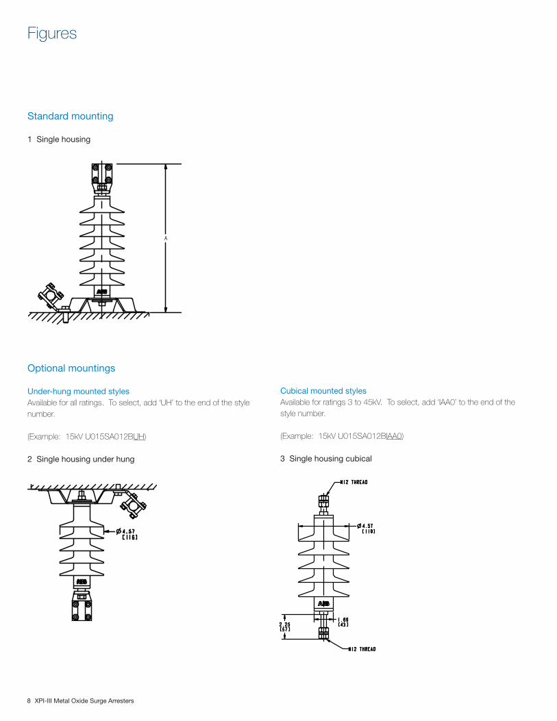
Standard mounting
1 Single housing
Figures
Optional mountings
Under-hung mounted stylesAvailable for all ratings. To select, add ‘UH’ to the end of the style number.
(Example: 15kV U015SA012BUH)
2 Single housing under hung
Cubical mounted stylesAvailable for ratings 3 to 45kV. To select, add ‘IAA0’ to the end of the style number.
(Example: 15kV U015SA012BIAA0)
3 Single housing cubical
A
XPI-III Metal Oxide Surge Arresters 9
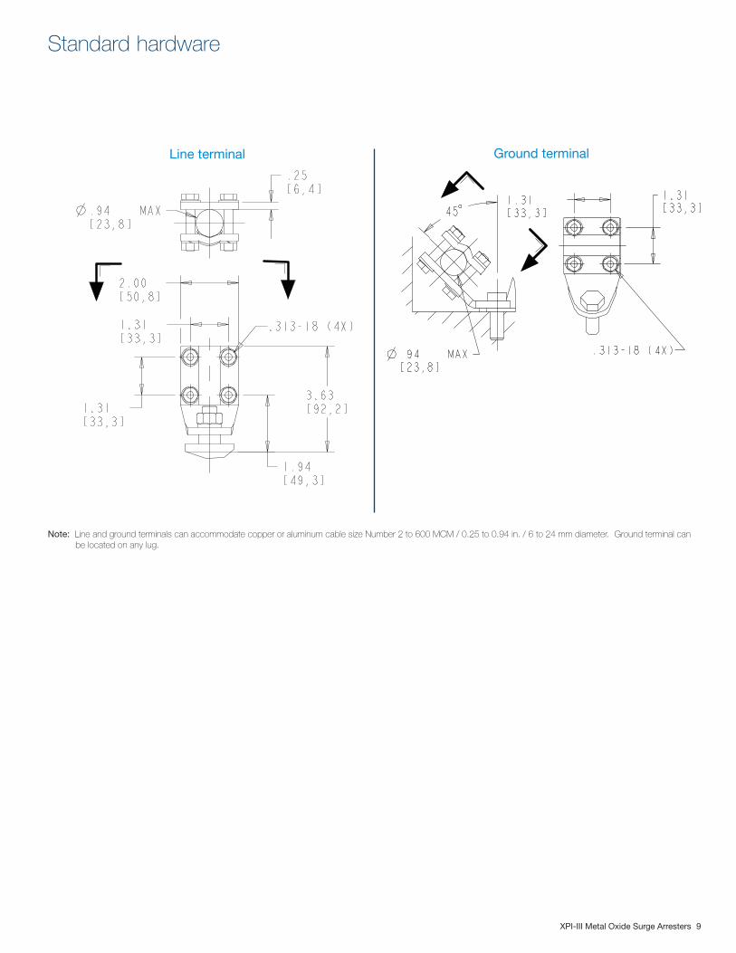
Standard hardware
Line terminal Ground terminal
Note: Line and ground terminals can accommodate copper or aluminum cable size Number 2 to 600 MCM / 0.25 to 0.94 in. / 6 to 24 mm diameter. Ground terminal can be located on any lug.
10 XPI-III Metal Oxide Surge Arresters
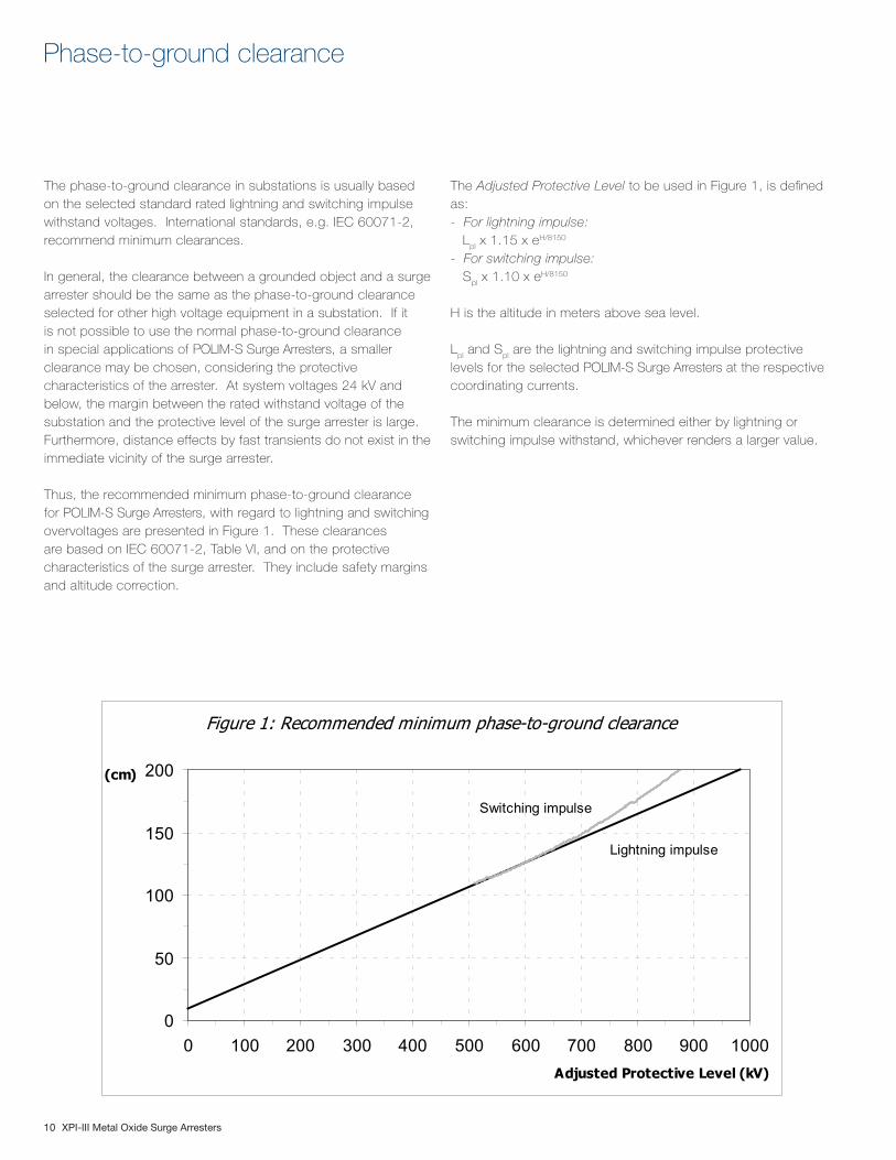
The phase-to-ground clearance in substations is usually based on the selected standard rated lightning and switching impulse withstand voltages. International standards, e.g. IEC 60071-2, recommend minimum clearances.
In general, the clearance between a grounded object and a surge arrester should be the same as the phase-to-ground clearance selected for other high voltage equipment in a substation. If it is not possible to use the normal phase-to-ground clearance in special applications of POLIM-S Surge Arresters, a smaller clearance may be chosen, considering the protective characteristics of the arrester. At system voltages 24 kV and below, the margin between the rated withstand voltage of the substation and the protective level of the surge arrester is large. Furthermore, distance effects by fast transients do not exist in the immediate vicinity of the surge arrester.
Thus, the recommended minimum phase-to-ground clearance for POLIM-S Surge Arresters, with regard to lightning and switching overvoltages are presented in Figure 1. These clearances are based on IEC 60071-2, Table VI, and on the protective characteristics of the surge arrester. They include safety margins and altitude correction.
Phase-to-ground clearance
The Adjusted Protective Level to be used in Figure 1, is defined as:- For lightning impulse: Lpl
x 1.15 x eH/8150
- For switching impulse: S
pl x 1.10 x eH/8150
H is the altitude in meters above sea level.
Lpl and S
pl are the lightning and switching impulse protective
levels for the selected POLIM-S Surge Arresters at the respective coordinating currents.
The minimum clearance is determined either by lightning or switching impulse withstand, whichever renders a larger value.
Figure 1: Recommended minimum phase-to-ground clearance
Lightning impulse
Switching impulse
0
50
100
150
200
0 100 200 300 400 500 600 700 800 900 1000Adjusted Protective Level (kV)
(cm)
XPI-III Metal Oxide Surge Arresters 11
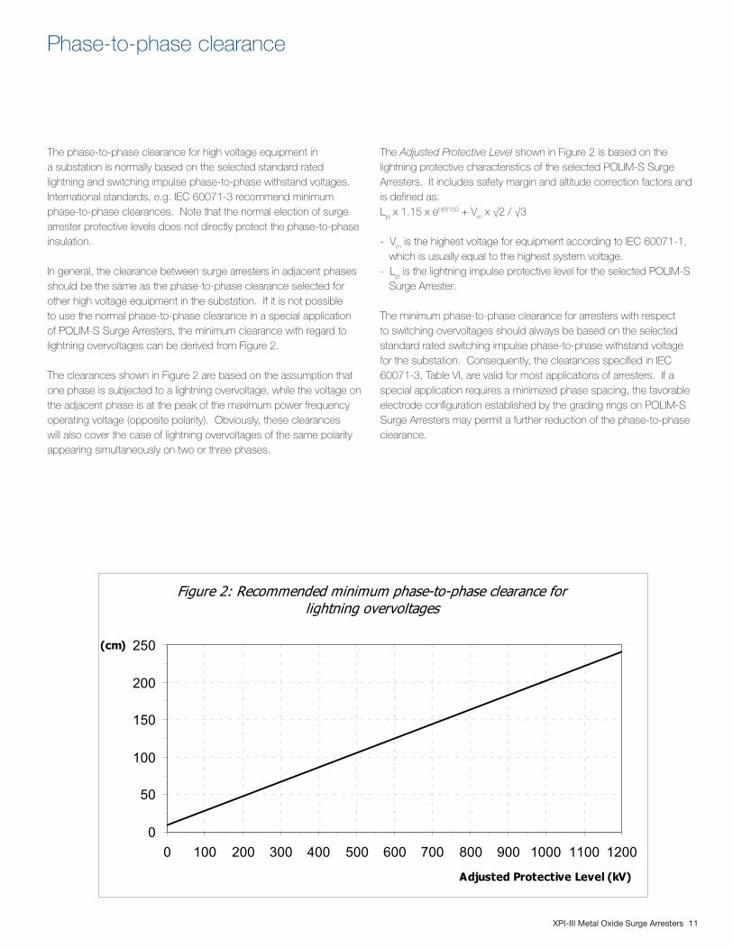
Figure 2: Recommended minimum phase-to-phase clearance for lightning overvoltages
0
50
100
150
200
250
0 100 200 300 400 500 600 700 800 900 1000 1100 1200
Adjusted Protective Level (kV)
(cm)
The phase-to-phase clearance for high voltage equipment in a substation is normally based on the selected standard rated lightning and switching impulse phase-to-phase withstand voltages. International standards, e.g. IEC 60071-3 recommend minimum phase-to-phase clearances. Note that the normal election of surge arrester protective levels does not directly protect the phase-to-phase insulation.
In general, the clearance between surge arresters in adjacent phases should be the same as the phase-to-phase clearance selected for other high voltage equipment in the substation. If it is not possible to use the normal phase-to-phase clearance in a special application of POLIM-S Surge Arresters, the minimum clearance with regard to lightning overvoltages can be derived from Figure 2.
The clearances shown in Figure 2 are based on the assumption that one phase is subjected to a lightning overvoltage, while the voltage on the adjacent phase is at the peak of the maximum power frequency operating voltage (opposite polarity). Obviously, these clearances will also cover the case of lightning overvoltages of the same polarity appearing simultaneously on two or three phases.
Phase-to-phase clearance
The Adjusted Protective Level shown in Figure 2 is based on the lightning protective characteristics of the selected POLIM-S Surge Arresters. It includes safety margin and altitude correction factors and is defined as:Lpl
x 1.15 x eH/8150 + Vm x √2 / √3
- Vm is the highest voltage for equipment according to IEC 60071-1,
which is usually equal to the highest system voltage.- Lpl
is the lightning impulse protective level for the selected POLIM-S Surge Arrester.
The minimum phase-to-phase clearance for arresters with respect to switching overvoltages should always be based on the selected standard rated switching impulse phase-to-phase withstand voltage for the substation. Consequently, the clearances specified in IEC 60071-3, Table VI, are valid for most applications of arresters. If a special application requires a minimized phase spacing, the favorable electrode configuration established by the grading rings on POLIM-S Surge Arresters may permit a further reduction of the phase-to-phase clearance.
Contact us
Doc
umen
t N
umb
er:
2G
NM
1100
06 /
Ap
ril 2
01
3ABB Inc. High Voltage Products - Surge Arresters100 Distribution Circle Mount Pleasant, Pennsylvania 15666, USA Phone: +1 (724) 696-1568 Fax: +1 (724) 696-1502 www.abb.us