Embed Size (px)
Citation preview
Polymeric Surge Arrester upto 550 kVCatalogue 2008
Energy Division

1
Content
Installations 2
Introduction 3
Application 3
Benefits 3
Design Concept
I. Single Modules for series parallel surge arresters 4
A. Construction 4
B. Housing material 4
II. The Module Series Parallel Design 5
A. Voltage distribution and stress grading 5
B. Thermal ageing and partial discharge 5
C. Comparison between Series Parallel and single column design 6
D. Electrical tests for Series Parallel surge arrester 6
E. Advantages of the Series Parallel design 6
Appropriate Surge Arrester Selection
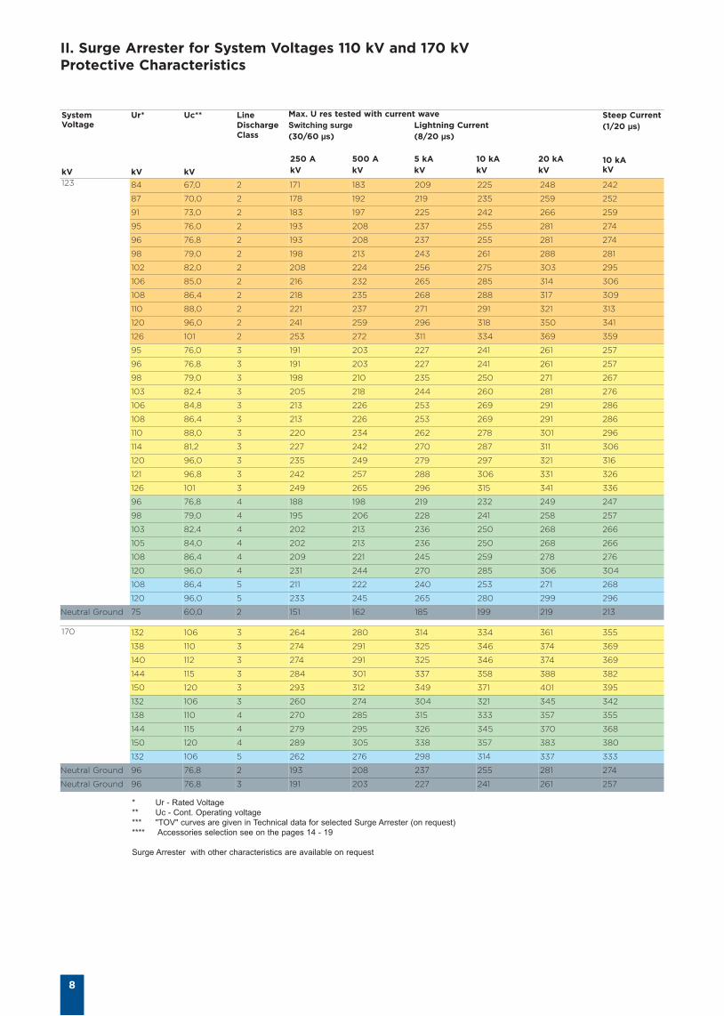
I. Electrical performance and housings 7
II. Surge Arresters for System Voltages 123 kV and 170 kV 8
III. Surge Arresters for System Voltages 245 kV and 362 kV 10
IV. Surge Arresters for System Voltages 420 kV and 550 kV 12
V. Accessories 16
VI.Transmission Line Surge Arresters for Overhead Poles andOverhead Lines up to 150 kV 20
Additional Equipment
Surge Counter 22
Tyco Electronics´s total commitment to quality 23
Tyco Electronics presents the complete solution 24
2
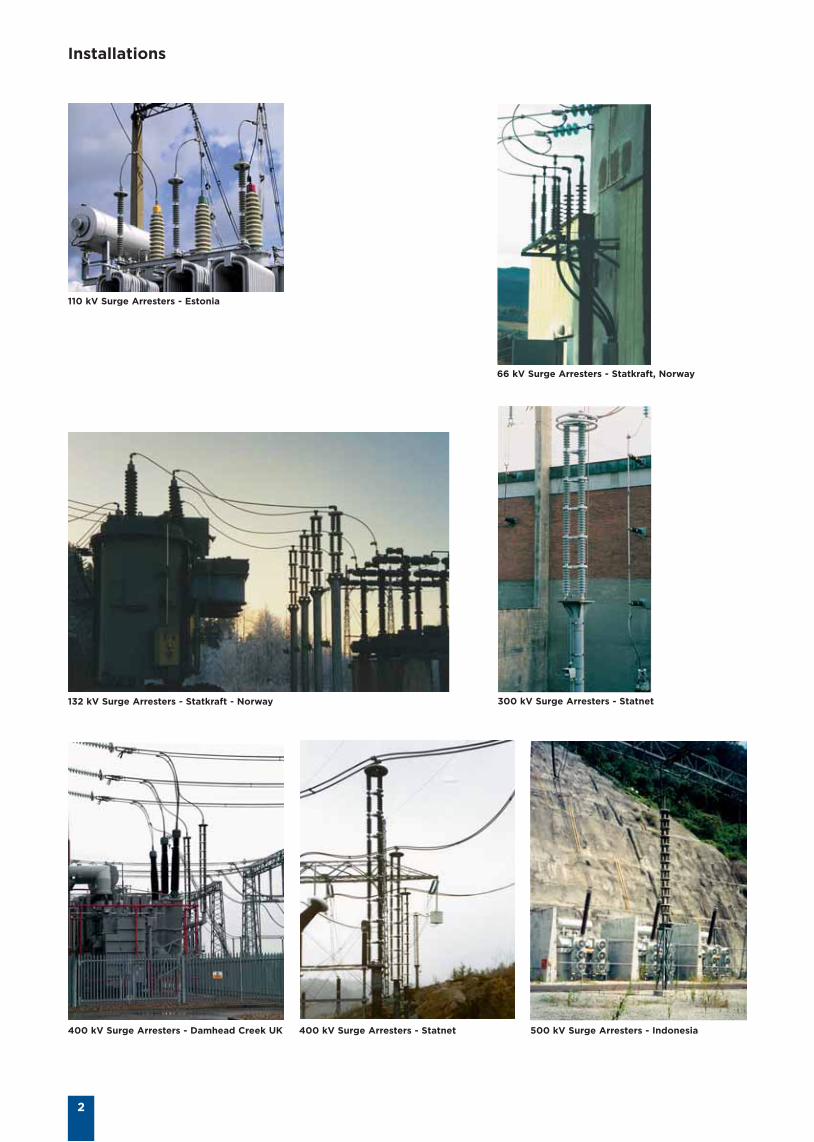
Installations
110 kV Surge Arresters - Estonia
66 kV Surge Arresters - Statkraft, Norway
132 kV Surge Arresters - Statkraft - Norway 300 kV Surge Arresters - Statnet
400 kV Surge Arresters - Damhead Creek UK 400 kV Surge Arresters - Statnet 500 kV Surge Arresters - Indonesia
3
Introduction
Tyco Electronics has beenmanufacturing surge arresters forover 60 years. Our knowledge andexperience we use to develop oursurge arrester range today.
Tyco Electronics is well known fortheir insulation and protectionproducts worldwide. The range of HVsurge arresters up to 550 kV and linedischarge classes from 2 up to 5operates in 130 countries in diverseclimates from the artic circle to thetropics.
Since 1988 Tyco Electronics havedesigned the patented series parallelmetal oxide surge arrester whichunique in construction and providesmany advantages over conventionalsingle column and multiple columnsporcelain and polymeric housedarresters. They were designed andtested to meet defined abnormalservice conditions as detailed inAnnex A of IEC 60099-4 (1991).
The unique construction of this seriesparallel surge arrester provideselectrical and mechanical propertiesthat cannot be obtained with singleor multiple column types. In particularthe geometry and unitaryconstruction provides inherentvoltage grading that does not requireadditional grading rings or furthercorrection of the maximum continousoperating voltage (Uc) required forarresters of conventionalconstruction.
Application
This range of Silicone Rubber housedsurge arresters is applicable forsubstation equipment andtransmission lines. Because of theirhigh cantilever strength, they n bused to replace the able supportinsulators n HV terminations. Thisresults in simplified installation for HVterminations at reduced cost which isaesthetically m acceptabIe to thegeneral pubIic. It should b noted thatthis type of installation n not bachieved with other surge arresters oflower strength construction.
Benefits
• Low residual voltages
• Superior protection margins
• Superior TOV performance
• Inbuilt stress grading along the full length
• More effective grading per unit length than a single column type
• Similar stress distribution like single column type, but without stressgrading ring
• Resistant against Radial stress based on the gap free Bowthorpepatented construction
• Safe non-shattering short circuit behavior to higher current levels
• High-energy handling • Direct molded housing to prevent moistureingress
• Hydrophobic and tracking and erosion resistant silicone housing
• Superior pollution performance
• Excellent cantilever and tensile performance
• Excellent mechanical, vibration and impact withstand capability
• Extremely strong mechanical strength
• Low thermal ageing of varistor insulation
• Smaller footprint than equivalent single column SA with grading ring
• Modular design for quick installation and commission
• Light weight
• Capable to withstand seismic condition
• Uniform current sharing
• Maintenance free
• Tested in accordance with IEC60099-4 at independent accreditedlaboratories
• Certified to GOST requirements and has accreditation in RussianFederal network and Ukraine Power Ministry
• Quality design and manufacturing, ISO 9001 and 14001 compliant
Design Concept
4
1-column porcelain housed and non-integrated polymeric housed typesurge arresters have a lot ofweaknesses. A few of them are thecontrol of uniform stress grading andthe radial field strength which are themost important issues in these surgearrester design types. The high radialfield would lead to discharge in thesurge arrester enclosure between theporcelain inside and the metal oxidevaristors.
I. Single Modules for Series ParallelSurge Arrester
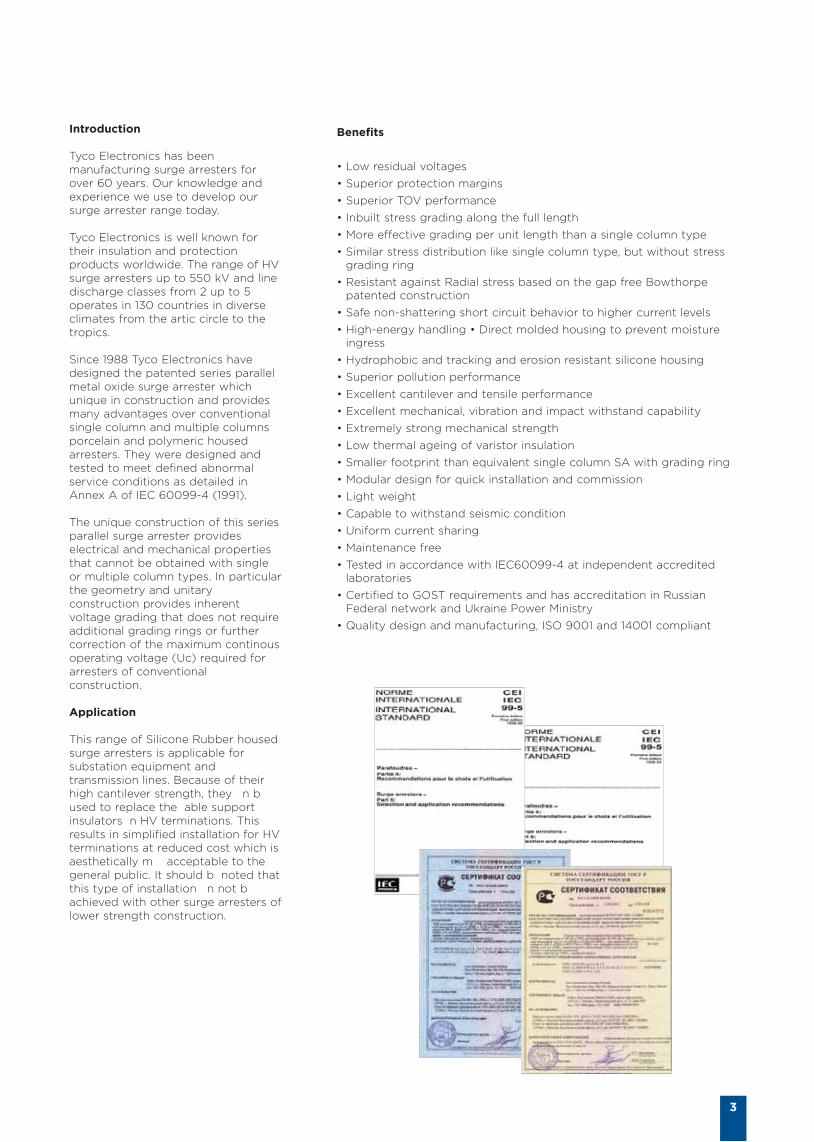
A. Construction
The Tyco Electronics Bowthorpepatented surge arrester constructionovercame this weakness byeliminating this air gap by directmoulding of the silicone rubberhousing onto the wrapped ZnOvaristor elements and the terminalassembly. The applied ZnO varistorsensure a very good electricalbehaviour. The polymeric housingand the shed form (figure 1a) showsa good performance in salt-fog tests.
Stainless SteelTerminal Block
Aluminium End Block
Silicone RubberHousing
Heat Sink
ZnO VaristorElement
Die CastAluminium SealingEnd
Corona Ring
Intermediatemetal work
Insualtedbase
Figure 1a: Tyco Electronics Bowthorpe surge arrester core and series parallelarrester
Excellent hydrophobicity
Safe non-shattering failure mode
Track and erosion resistant
B. Housing material
Housing material is service provenformulation of Silicone Rubber. Thesilicone housing was developed usingthe knowledge accumulated over 35years of internal Tyco Electronicsmaterials science expertise andexperience, resulting in an optimumshed profile and a material withexcellent tracking and erosionresistance. This range of SiliconeRubber housed surge arresters hasb n fully tested to meet the verysevere pressure-relief tests.
Thermal ageing of the varistor would becaused by the lack of self limiting underthe combination of high stress and lowsource impedance. The series parallelsurge arrester design has eliminatedboth, thermal and partial dischargeageing to the metal oxide arrester. TheSeries Parallel surge arrester has nointernal air gaps and therefore requiresno grading ring to avoid internalionisation.
5
II. The Module Series Parallel Design
A. Voltage distribution and stressgrading
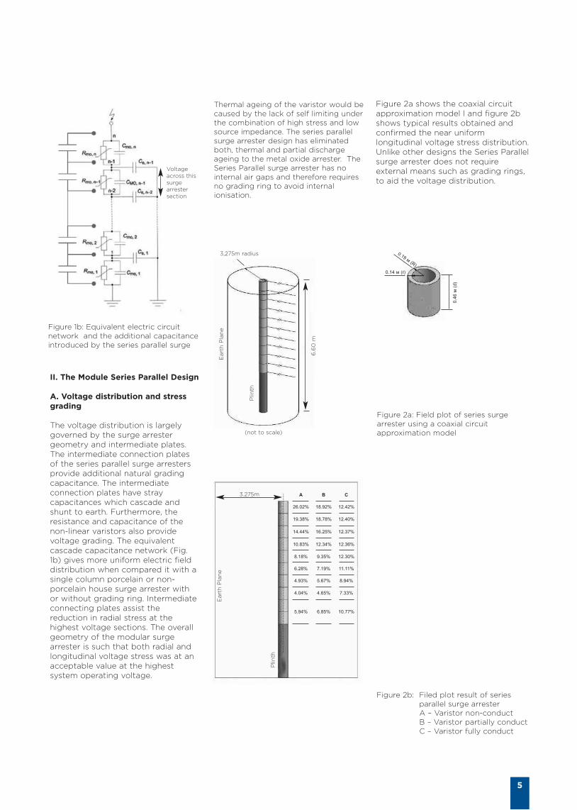
The voltage distribution is largelygoverned by the surge arrestergeometry and intermediate plates.The intermediate connection platesof the series parallel surge arrestersprovide additional natural gradingcapacitance. The intermediateconnection plates have straycapacitances which cascade andshunt to earth. Furthermore, theresistance and capacitance of thenon-linear varistors also providevoltage grading. The equivalentcascade capacitance network (Fig.1b) gives more uniform electric fielddistribution when compared it with asingle column porcelain or non-porcelain house surge arrester withor without grading ring. Intermediateconnecting plates assist thereduction in radial stress at thehighest voltage sections. The overallgeometry of the modular surgearrester is such that both radial andlongitudinal voltage stress was at anacceptable value at the highestsystem operating voltage.
(not to scale)
3,275m radius
6.6
0 m
Eart
h P
lan
e
Plin
th
0.4
6 м
(d
)
0.19 м (R)
0.14 м (r)
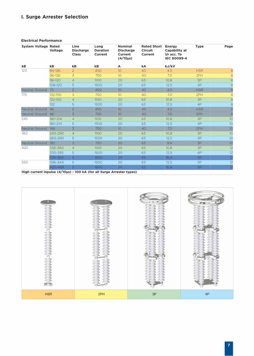
26.02% 18.92% 12.42%
A B C
19.38% 18.78% 12.40%
14.44% 16.25% 12.37%
10.83% 12.34% 12.36%
8.18% 9.35% 12.30%
6.28% 7.19% 11.11%
4.93% 5.67% 8.94%
4.04% 4.65% 7.33%
5.94% 6.85% 10.77%
3.275m
Eart
h P
lan
e
Plin
th
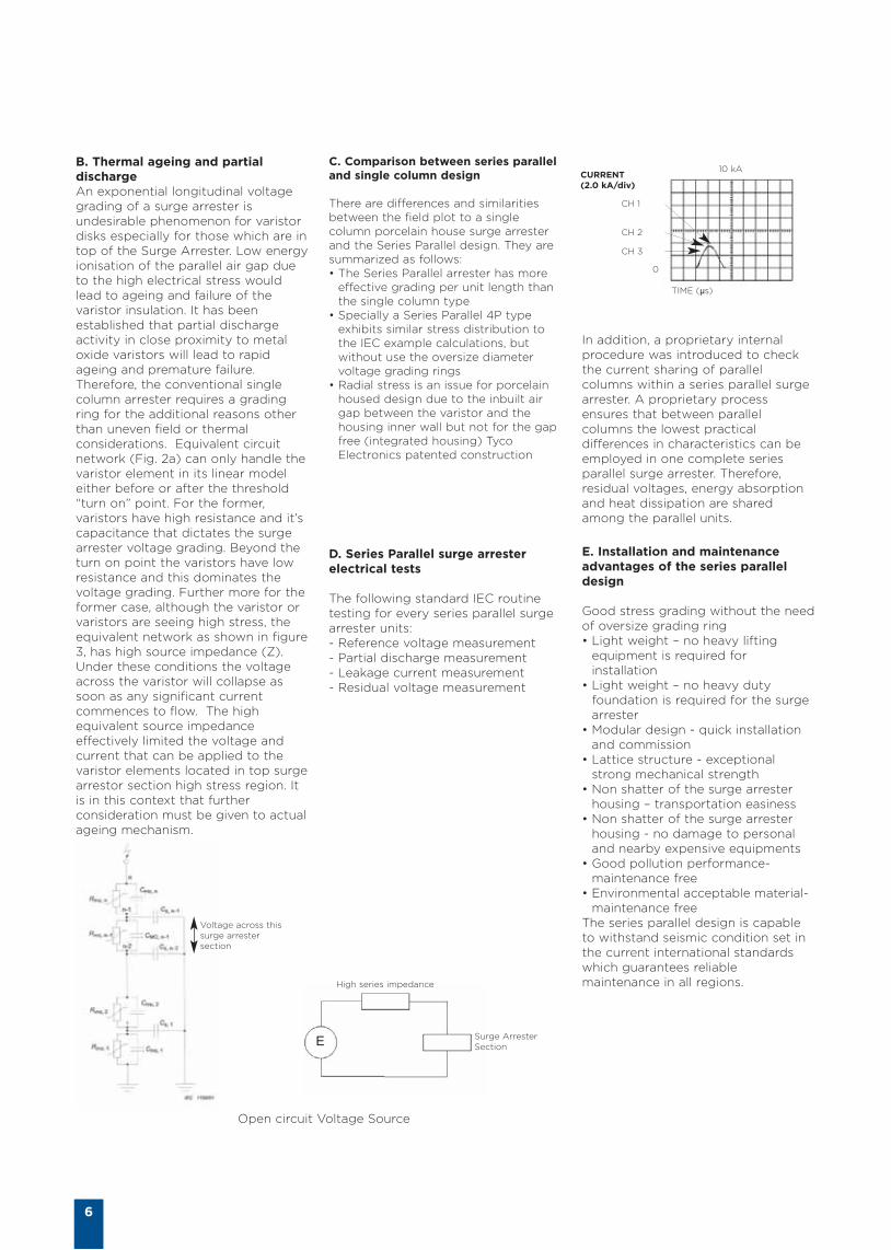
Figure 2a: Field plot of series surgearrester using a coaxial circuitapproximation model
Figure 2b: Filed plot result of seriesparallel surge arrester A – Varistor non-conduct B – Varistor partially conduct C – Varistor fully conduct
Figure 1b: Equivalent electric circuitnetwork and the additional capacitanceintroduced by the series parallel surge
Voltageacross thissurgearrestersection
Figure 2a shows the coaxial circuitapproximation model l and figure 2bshows typical results obtained andconfirmed the near uniformlongitudinal voltage stress distribution.Unlike other designs the Series Parallelsurge arrester does not requireexternal means such as grading rings,to aid the voltage distribution.
In addition, a proprietary internalprocedure was introduced to checkthe current sharing of parallelcolumns within a series parallel surgearrester. A proprietary processensures that between parallelcolumns the lowest practicaldifferences in characteristics can beemployed in one complete seriesparallel surge arrester. Therefore,residual voltages, energy absorptionand heat dissipation are sharedamong the parallel units.
E. Installation and maintenanceadvantages of the series paralleldesign
Good stress grading without the needof oversize grading ring • Light weight – no heavy lifting
equipment is required forinstallation
• Light weight – no heavy dutyfoundation is required for the surgearrester
• Modular design - quick installationand commission
• Lattice structure - exceptionalstrong mechanical strength
• Non shatter of the surge arresterhousing – transportation easiness
• Non shatter of the surge arresterhousing - no damage to personaland nearby expensive equipments
• Good pollution performance-maintenance free
• Environmental acceptable material-maintenance free
The series parallel design is capableto withstand seismic condition set inthe current international standardswhich guarantees reliablemaintenance in all regions.
TIME (µs)
0
CURRENT(2.0 kA/div)
CH 1
CH 2
CH 3
10 kAC. Comparison between series paralleland single column design
There are differences and similaritiesbetween the field plot to a singlecolumn porcelain house surge arresterand the Series Parallel design. They aresummarized as follows: • The Series Parallel arrester has more
effective grading per unit length thanthe single column type
• Specially a Series Parallel 4P typeexhibits similar stress distribution tothe IEC example calculations, butwithout use the oversize diametervoltage grading rings
• Radial stress is an issue for porcelainhoused design due to the inbuilt airgap between the varistor and thehousing inner wall but not for the gapfree (integrated housing) TycoElectronics patented construction
D. Series Parallel surge arresterelectrical tests
The following standard IEC routinetesting for every series parallel surgearrester units:- Reference voltage measurement - Partial discharge measurement - Leakage current measurement - Residual voltage measurement
6
B. Thermal ageing and partialdischarge An exponential longitudinal voltagegrading of a surge arrester isundesirable phenomenon for varistordisks especially for those which are intop of the Surge Arrester. Low energyionisation of the parallel air gap dueto the high electrical stress wouldlead to ageing and failure of thevaristor insulation. It has beenestablished that partial dischargeactivity in close proximity to metaloxide varistors will lead to rapidageing and premature failure.Therefore, the conventional singlecolumn arrester requires a gradingring for the additional reasons otherthan uneven field or thermalconsiderations. Equivalent circuitnetwork (Fig. 2a) can only handle thevaristor element in its linear modeleither before or after the threshold“turn on” point. For the former,varistors have high resistance and it’scapacitance that dictates the surgearrester voltage grading. Beyond theturn on point the varistors have lowresistance and this dominates thevoltage grading. Further more for theformer case, although the varistor orvaristors are seeing high stress, theequivalent network as shown in figure3, has high source impedance (Z).Under these conditions the voltageacross the varistor will collapse assoon as any significant currentcommences to flow. The highequivalent source impedanceeffectively limited the voltage andcurrent that can be applied to thevaristor elements located in top surgearrestor section high stress region. Itis in this context that furtherconsideration must be given to actualageing mechanism.
E
Voltage across thissurge arrestersection
High series impedance
Surge ArresterSection
Open circuit Voltage Source
I. Surge Arrester Selection
7
HSR 2PH 3P 4P
System Voltage
kB
RatedVoltage
kB
LineDischargeClass
kB
LongDurationCurrent
kB
NominalDischargeCurrent(4/10µs)
A
Rated ShortCircuitCurrent
kA
EnergyCapability atUr acc. ToIEC 60099-4
kJ/kV
Type Page
123 84-126 2 450 10 40 4,5 HSR 8
96-126 3 750 10 40 7,0 2PH 8
96-120 4 1100 20 63 10,8 3P 8
108-120 5 1500 20 63 12,5 4P 8
Neutral Ground 75 2 450 10 40 4,5 HSR 8
170 132-150 3 750 10 40 7,0 2PH 8
132-150 4 1100 20 63 10,8 3P 8
132 5 1500 20 63 12,5 4P 8
Neutral Ground 96 2 450 10 40 4,5 HSR 8
Neutral Ground 96 3 750 10 40 7,0 2PH 8
245 180-214 4 1100 20 63 10,8 3P 10
180-214 5 1500 20 63 12,5 4P 10
Neutral Ground 168 3 750 10 40 7,0 2PH 10
362 240-290 4 1100 20 63 10,8 3P 10
260-290 5 1500 20 63 12,5 4P 10
Neutral Ground 180 3 750 20 63 9,4 3P 10
420 336-360 4 1100 20 63 10,8 3P 12
330-393 5 1500 20 63 12,5 4P 12
336-360 5 1800 20 63 16,4 5P 12
550 396-444 5 1500 20 63 12,5 4P 12
420-468 5 1800 20 63 16,4 5P 12
High current inpulse (4/10µs) - 100 kA (for all Surge Arrester types)
Electrical Performance
II. Surge Arrester for System Voltages 110 kV and 170 kVProtective Characteristics
8
SystemVoltage
kV
Ur*
kV
Uc**
kV
LineDischargeClass
Max. U res tested with current waveSwitching surge Lightning Current(30/60 µs) (8/20 µs)
250 A 500 A 5 kA 10 kA 20 kAkV kV kV kV kV
Steep Current(1/20 µs)
10 kAkV
123 84 67,0 2 171 183 209 225 248 242
87 70,0 2 178 192 219 235 259 252
91 73,0 2 183 197 225 242 266 259
95 76,0 2 193 208 237 255 281 274
96 76,8 2 193 208 237 255 281 274
98 79,0 2 198 213 243 261 288 281
102 82,0 2 208 224 256 275 303 295
106 85,0 2 216 232 265 285 314 306
108 86,4 2 218 235 268 288 317 309
110 88,0 2 221 237 271 291 321 313
120 96,0 2 241 259 296 318 350 341
126 101 2 253 272 311 334 369 359
95 76,0 3 191 203 227 241 261 257
96 76,8 3 191 203 227 241 261 257
98 79,0 3 198 210 235 250 271 267
103 82,4 3 205 218 244 260 281 276
106 84,8 3 213 226 253 269 291 286
108 86,4 3 213 226 253 269 291 286
110 88,0 3 220 234 262 278 301 296
114 81,2 3 227 242 270 287 311 306
120 96,0 3 235 249 279 297 321 316
121 96,8 3 242 257 288 306 331 326
126 101 3 249 265 296 315 341 336
96 76,8 4 188 198 219 232 249 247
98 79,0 4 195 206 228 241 258 257
103 82,4 4 202 213 236 250 268 266
105 84,0 4 202 213 236 250 268 266
108 86,4 4 209 221 245 259 278 276
120 96,0 4 231 244 270 285 306 304
108 86,4 5 211 222 240 253 271 268
120 96,0 5 233 245 265 280 299 296
Neutral Ground 75 60,0 2 151 162 185 199 219 213
170 132 106 3 264 280 314 334 361 355
138 110 3 274 291 325 346 374 369
140 112 3 274 291 325 346 374 369
144 115 3 284 301 337 358 388 382
150 120 3 293 312 349 371 401 395
132 106 3 260 274 304 321 345 342
138 110 4 270 285 315 333 357 355
144 115 4 279 295 326 345 370 368
150 120 4 289 305 338 357 383 380
132 106 5 262 276 298 314 337 333
Neutral Ground 96 76,8 2 193 208 237 255 281 274
Neutral Ground 96 76,8 3 191 203 227 241 261 257
* Ur - Rated Voltage
** Uc - Cont. Operating voltage
*** "TOV" curves are given in Technical data for selected Surge Arrester (on request)
**** Accessories selection see on the pages 14 - 19
Surge Arrester with other characteristics are available on request
9
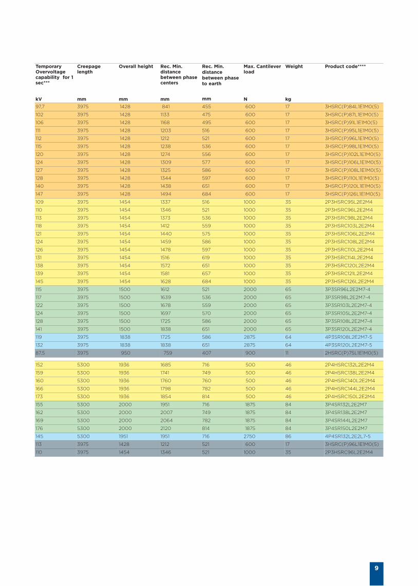
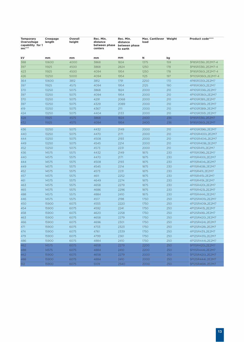
TemporaryOvervoltagecapability for 1sec***
kV
Creepage length
mm
Overall height
mm
Rec. Min.distancebetween phasecenters
mm
Rec. Min.distancebetween phaseto earth
mm
Max. Cantileverload
N
Weight
kg
Product code****
97,7 3975 1428 841 455 600 17 3HSRC(P)84L1E1M0(5)
102 3975 1428 1133 475 600 17 3HSRC(P)87L1E1M0(5)
106 3975 1428 1168 495 600 17 3HSRC(P)91L1E1M0(5)
111 3975 1428 1203 516 600 17 3HSRC(P)95L1E1M0(5)
112 3975 1428 1212 521 600 17 3HSRC(P)96L1E1M0(5)
115 3975 1428 1238 536 600 17 3HSRC(P)98L1E1M0(5)
120 3975 1428 1274 556 600 17 3HSRC(P)102L1E1M0(5)
124 3975 1428 1309 577 600 17 3HSRC(P)106L1E1M0(5)
127 3975 1428 1325 586 600 17 3HSRC(P)108L1E1M0(5)
128 3975 1428 1344 597 600 17 3HSRC(P)110L1E1M0(5)
140 3975 1428 1438 651 600 17 3HSRC(P)120L1E1M0(5)
147 3975 1428 1494 684 600 17 3HSRC(P)126L1E1M0(5)
109 3975 1454 1337 516 1000 35 2P3HSRC95L2E2M4
110 3975 1454 1346 521 1000 35 2P3HSRC96L2E2M4
113 3975 1454 1373 536 1000 35 2P3HSRC98L2E2M4
118 3975 1454 1412 559 1000 35 2P3HSRC103L2E2M4
121 3975 1454 1440 575 1000 35 2P3HSRC106L2E2M4
124 3975 1454 1459 586 1000 35 2P3HSRC108L2E2M4
126 3975 1454 1478 597 1000 35 2P3HSRC110L2E2M4
131 3975 1454 1516 619 1000 35 2P3HSRC114L2E2M4
138 3975 1454 1572 651 1000 35 2P3HSRC120L2E2M4
139 3975 1454 1581 657 1000 35 2P3HSRC121L2E2M4
145 3975 1454 1628 684 1000 35 2P3HSRC126L2E2M4
115 3975 1500 1612 521 2000 65 3P3SR96L2E2M7-4
117 3975 1500 1639 536 2000 65 3P3SR98L2E2M7-4
122 3975 1500 1678 559 2000 65 3P3SR103L2E2M7-4
124 3975 1500 1697 570 2000 65 3P3SR105L2E2M7-4
128 3975 1500 1725 586 2000 65 3P3SR108L2E2M7-4
141 3975 1500 1838 651 2000 65 3P3SR120L2E2M7-4
119 3975 1838 1725 586 2875 64 4P3SR108L2E2M7-5
132 3975 1838 1838 651 2875 64 4P3SR120L2E2M7-5
87,5 3975 950 759 407 900 11 2HSRC(P)75L1E1M0(5)
152 5300 1936 1685 716 500 46 2P4HSRC132L2E2M4
159 5300 1936 1741 749 500 46 2P4HSRC138L2E2M4
160 5300 1936 1760 760 500 46 2P4HSRC140L2E2M4
166 5300 1936 1798 782 500 46 2P4HSRC144L2E2M4
173 5300 1936 1854 814 500 46 2P4HSRC150L2E2M4
155 5300 2000 1951 716 1875 84 3P4SR132L2E2M7
162 5300 2000 2007 749 1875 84 3P4SR138L2E2M7
169 5300 2000 2064 782 1875 84 3P4SR144L2E2M7
176 5300 2000 2120 814 1875 84 3P4SR150L2E2M7
145 5300 1951 1951 716 2750 86 4P4SR132L2E2L7-5
113 3975 1428 1212 521 600 17 3HSRC(P)96L1E1M0(5)
110 3975 1454 1346 521 1000 35 2P3HSRC96L2E2M4
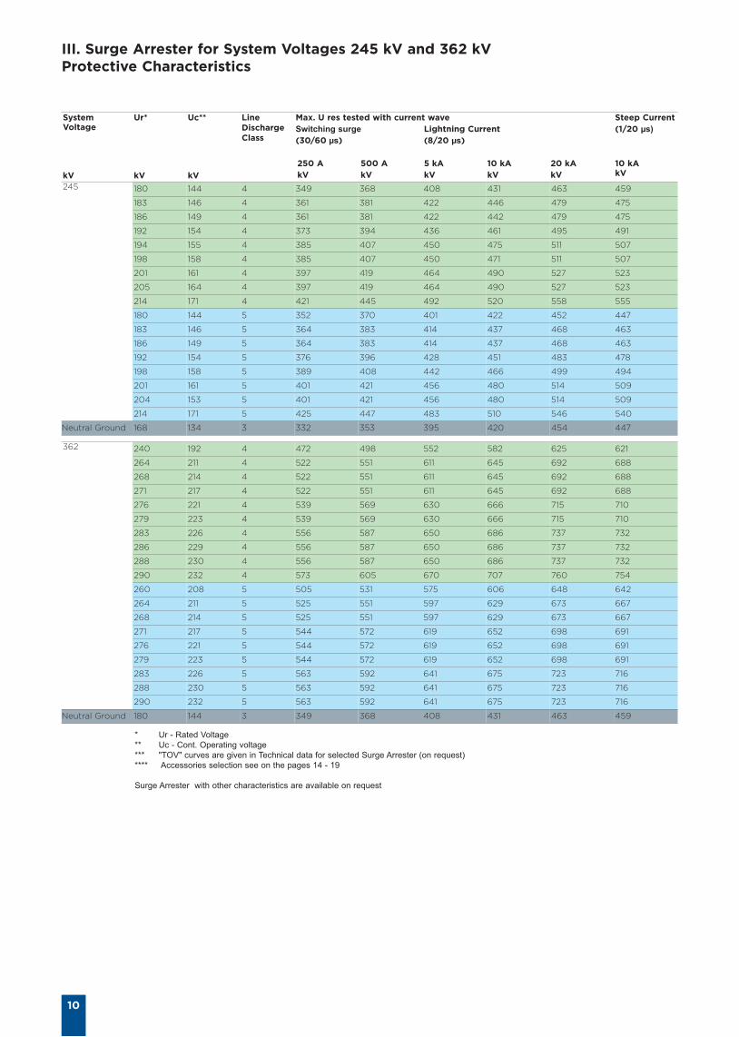
III. Surge Arrester for System Voltages 245 kV and 362 kVProtective Characteristics
10
SystemVoltage
kV
Ur*
kV
Uc**
kV
LineDischargeClass
Max. U res tested with current waveSwitching surge Lightning Current(30/60 µs) (8/20 µs)
250 A 500 A 5 kA 10 kA 20 kAkV kV kV kV kV
Steep Current (1/20 µs)
10 kAkV
245 180 144 4 349 368 408 431 463 459
183 146 4 361 381 422 446 479 475
186 149 4 361 381 422 442 479 475
192 154 4 373 394 436 461 495 491
194 155 4 385 407 450 475 511 507
198 158 4 385 407 450 471 511 507
201 161 4 397 419 464 490 527 523
205 164 4 397 419 464 490 527 523
214 171 4 421 445 492 520 558 555
180 144 5 352 370 401 422 452 447
183 146 5 364 383 414 437 468 463
186 149 5 364 383 414 437 468 463
192 154 5 376 396 428 451 483 478
198 158 5 389 408 442 466 499 494
201 161 5 401 421 456 480 514 509
204 153 5 401 421 456 480 514 509
214 171 5 425 447 483 510 546 540
Neutral Ground 168 134 3 332 353 395 420 454 447
362 240 192 4 472 498 552 582 625 621
264 211 4 522 551 611 645 692 688
268 214 4 522 551 611 645 692 688
271 217 4 522 551 611 645 692 688
276 221 4 539 569 630 666 715 710
279 223 4 539 569 630 666 715 710
283 226 4 556 587 650 686 737 732
286 229 4 556 587 650 686 737 732
288 230 4 556 587 650 686 737 732
290 232 4 573 605 670 707 760 754
260 208 5 505 531 575 606 648 642
264 211 5 525 551 597 629 673 667
268 214 5 525 551 597 629 673 667
271 217 5 544 572 619 652 698 691
276 221 5 544 572 619 652 698 691
279 223 5 544 572 619 652 698 691
283 226 5 563 592 641 675 723 716
288 230 5 563 592 641 675 723 716
290 232 5 563 592 641 675 723 716
Neutral Ground 180 144 3 349 368 408 431 463 459
* Ur - Rated Voltage
** Uc - Cont. Operating voltage
*** "TOV" curves are given in Technical data for selected Surge Arrester (on request)
**** Accessories selection see on the pages 14 - 19
Surge Arrester with other characteristics are available on request
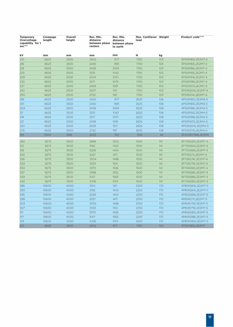
11
TemporaryOvervoltagecapability for 1sec***
kV
Creepage length
mm
Overall height
mm
Rec. Min.distancebetween phasecenters
mm
Rec. Min.distancebetween phaseto earth
mm
Max. Cantileverload
N
Weight
kg
Product code****
210 6625 2500 2402 977 1750 103 3P5SR180L2E2M7-4
216 6625 2500 2430 993 1750 103 3P5SR183L2E2M7-4
219 6625 2500 2458 1009 1750 103 3P5SR186L2E2M7-4
225 6625 2500 2515 1042 1750 103 3P5SR192L2E2M7-4
229 6625 2500 2534 1053 1750 103 3P5SR194L2E2M7-4
232 6625 2500 2571 1075 1750 103 3P5SR198L2E2M7-4
237 6625 2500 2599 1091 1750 103 3P5SR201L2E2M7-4
242 6625 2500 2637 1113 1750 103 3P5SR205L2E2M7-4
250 6625 2500 2722 1161 1750 103 3P5SR214L2E2M7-4
198 6625 2500 2402 977 2625 108 4P5SR180L2E2M4-5
201 6625 2500 2430 993 2625 108 4P5SR183L2E2M4-5
204 6625 2500 2458 1009 2625 108 4P5SR186L2E2M4-5
211 6625 2500 2515 1042 2625 108 4P5SR192L2E2M4-5
218 6625 2500 2571 1075 2625 108 4P5SR198L2E2M4-5
221 6625 2500 2599 1091 2625 108 4P5SR201L2E2M4-5
224 6625 2500 2628 1107 2625 108 4P5SR204L2E2M4-5
235 6625 2500 2722 1161 2625 108 4P5SR214L2E2M4-5
193 5300 1936 2023 912 500 46 2P4HSRC168L2E2M4
283 9275 3500 2966 1303 1500 141 3P7SR240L2E2M7-4
312 9275 3500 3192 1422 1500 141 3P7SR264L2E2M7-4
316 9275 3500 3229 1454 1500 141 3P7SR268L2E2M7-4
320 9275 3500 3257 1471 1500 141 3P7SR271L2E2M7-4
326 9275 3500 3304 1498 1500 141 3P7SR276L2E2M7-4
329 9275 3500 3333 1514 1500 141 3P7SR279L2E2M7-4
334 9275 3500 3370 1536 1500 141 3P7SR283L2E2M7-4
337 9275 3500 3398 1552 1500 141 3P7SR286L2E2M7-4
339 9275 3500 3417 1563 1500 141 3P7SR288L2E2M7-4
342 9275 3500 3436 1574 1500 141 3P7SR290L2E2M7-4
286 10600 4000 3154 1411 2250 170 4P8SR260L2E2M7-5
290 10600 4000 3192 1433 2250 170 4P8SR264L2E2M7-5
295 10600 4000 3229 1454 2250 170 4P8SR268L2E2M7-5
298 10600 4000 3257 1471 2250 170 4P8SR271L2E2M7-5
303 10600 4000 3304 1498 2250 170 4P8SR276L2E2M7-5
307 10600 4000 3333 1514 2250 170 4P8SR279L2E2M7-5
311 10600 4000 3370 1536 2250 170 4P8SR283L2E2M7-5
317 10600 4000 3417 1563 2250 170 4P8SR288L2E2M7-5
319 10600 4000 3436 1574 2250 170 4P8SR290L2E2M7-5
210 6625 3500 2402 977 1750 103 3P5SR180L2E2M7
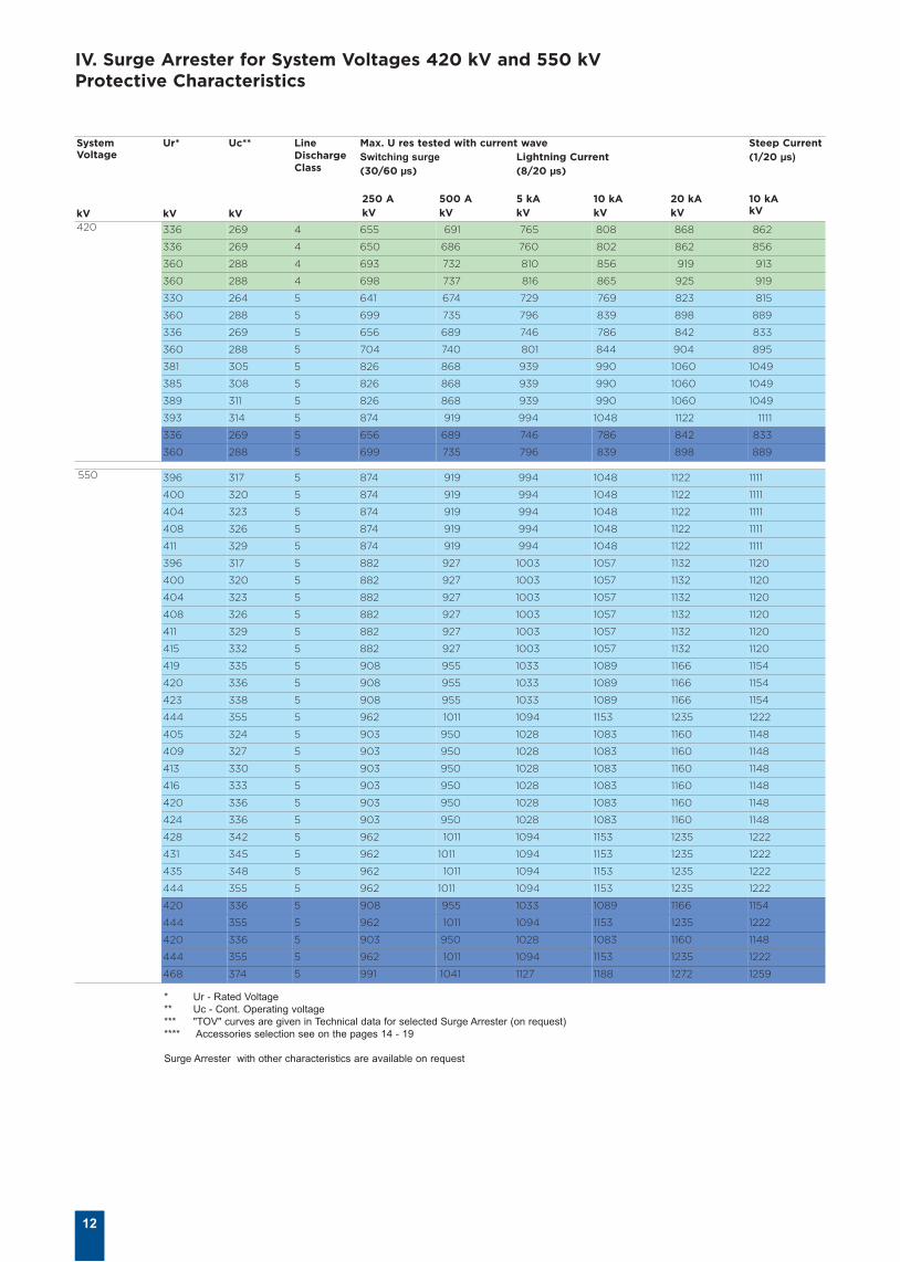
IV. Surge Arrester for System Voltages 420 kV and 550 kVProtective Characteristics
12
SystemVoltage
kV
Ur*
kV
Uc**
kV
LineDischargeClass
Max. U res tested with current waveSwitching surge Lightning Current(30/60 µs) (8/20 µs)
250 A 500 A 5 kA 10 kA 20 kAkV kV kV kV kV
Steep Current (1/20 µs)
10 kAkV
420 336 269 4 655 691 765 808 868 862
336 269 4 650 686 760 802 862 856
360 288 4 693 732 810 856 919 913
360 288 4 698 737 816 865 925 919
330 264 5 641 674 729 769 823 815
360 288 5 699 735 796 839 898 889
336 269 5 656 689 746 786 842 833
360 288 5 704 740 801 844 904 895
381 305 5 826 868 939 990 1060 1049
385 308 5 826 868 939 990 1060 1049
389 311 5 826 868 939 990 1060 1049
393 314 5 874 919 994 1048 1122 1111
336 269 5 656 689 746 786 842 833
360 288 5 699 735 796 839 898 889
550 396 317 5 874 919 994 1048 1122 1111
400 320 5 874 919 994 1048 1122 1111
404 323 5 874 919 994 1048 1122 1111
408 326 5 874 919 994 1048 1122 1111
411 329 5 874 919 994 1048 1122 1111
396 317 5 882 927 1003 1057 1132 1120
400 320 5 882 927 1003 1057 1132 1120
404 323 5 882 927 1003 1057 1132 1120
408 326 5 882 927 1003 1057 1132 1120
411 329 5 882 927 1003 1057 1132 1120
415 332 5 882 927 1003 1057 1132 1120
419 335 5 908 955 1033 1089 1166 1154
420 336 5 908 955 1033 1089 1166 1154
423 338 5 908 955 1033 1089 1166 1154
444 355 5 962 1011 1094 1153 1235 1222
405 324 5 903 950 1028 1083 1160 1148
409 327 5 903 950 1028 1083 1160 1148
413 330 5 903 950 1028 1083 1160 1148
416 333 5 903 950 1028 1083 1160 1148
420 336 5 903 950 1028 1083 1160 1148
424 336 5 903 950 1028 1083 1160 1148
428 342 5 962 1011 1094 1153 1235 1222
431 345 5 962 1011 1094 1153 1235 1222
435 348 5 962 1011 1094 1153 1235 1222
444 355 5 962 1011 1094 1153 1235 1222
420 336 5 908 955 1033 1089 1166 1154
444 355 5 962 1011 1094 1153 1235 1222
420 336 5 903 950 1028 1083 1160 1148
444 355 5 962 1011 1094 1153 1235 1222
468 374 5 991 1041 1127 1188 1272 1259
* Ur - Rated Voltage
** Uc - Cont. Operating voltage
*** "TOV" curves are given in Technical data for selected Surge Arrester (on request)
**** Accessories selection see on the pages 14 - 19
Surge Arrester with other characteristics are available on request
13
TemporaryOvervoltagecapability for 1sec***
kV
Creepage length
mm
Overall height
mm
Rec. Min.distancebetween phasecenters
mm
Rec. Min.distancebetween phaseto earth
mm
Max. Cantileverload
N
Weight
kg
Product code****
388 10600 4000 3868 1824 1375 159 3P8SR336L2E2M7-4
397 11925 4500 3868 2824 1250 178 3P9SR336L2E2M7-4
423 11925 4500 4094 1954 1250 178 3P9SR360L2E2M7-4
426 13250 5000 4094 1954 1125 197 3P10SR360L2E2M7-4
364 10600 3812 3812 1791 2250 170 4P8SR330L2E2M7
397 11925 4575 4094 1954 2125 190 4P9SR360L2E2M7
370 13250 5075 3868 1824 2000 210 4P10SR336L2E2M7
397 13250 5075 4094 1954 2000 210 4P10SR360L2E2M7
370 13250 5075 4291 2068 2000 210 4P10SR381L2E2M7
397 13250 5075 4329 2089 2000 210 4P10SR385L2E2M7
419 13250 5075 4367 2111 2000 210 4P10SR389L2E2M7
424 13250 5075 4404 2133 2000 210 4P10SR393L2E2M7
428 11925 4575 3868 1824 2400 236 5P9SR336L2E2M7
432 11925 4575 4094 1954 2400 236 5P9SR360L2E2M7
436 13250 5075 4432 2149 2000 210 4P10SR396L2E2M7
440 13250 5075 4470 2171 2000 210 4P10SR400L2E2M7
444 13250 5075 4508 2193 2000 210 4P10SR404L2E2M7
449 13250 5075 4545 2214 2000 210 4P10SR408L2E2M7
452 13250 5075 4573 2231 2000 210 4P10SR411L2E2M7
436 14575 5575 4432 2149 1875 230 4P11SR396L2E2M7
440 14575 5575 4470 2171 1875 230 4P11SR400L2E2M7
444 14575 5575 4508 2193 1875 230 4P11SR404L2E2M7
449 14575 5575 4545 2214 1875 230 4P11SR408L2E2M7
452 14575 5575 4573 2231 1875 230 4P11SR411L2E2M7
457 14575 5575 4611 2252 1875 230 4P11SR415L2E2M7
461 14575 5575 4649 2274 1875 230 4P11SR419L2E2M7
463 14575 5575 4658 2279 1875 230 4P11SR420L2E2M7
465 14575 5575 4686 2296 1875 230 4P11SR423L2E2M7
488 14575 5575 4884 2410 1875 230 4P11SR444L2E2M7
446 14575 5575 4517 2198 1750 250 4P12SR405L2E2M7
450 15900 6075 4555 2220 1750 250 4P12SR409L2E2M7
454 15900 6075 4592 2241 1750 250 4P12SR413L2E2M7
458 15900 6075 4620 2258 1750 250 4P12SR416L2E2M7
463 15900 6075 4658 2279 1750 250 4P12SR420L2E2M7
466 15900 6075 4696 2301 1750 250 4P12SR424L2E2M7
471 15900 6075 4733 2323 1750 250 4P12SR428L2E2M7
474 15900 6075 4761 2339 1750 250 4P12SR431L2E2M7
479 15900 6075 4799 2361 1750 250 4P12SR435L2E2M7
486 15900 6075 4884 2410 1750 250 4P12SR444L2E2M7
462 14575 6075 4658 2279 2200 250 5P11SR420L2E2M7
488 14575 6075 4884 2410 2200 250 5P11SR444L2E2M7
462 15900 6075 4658 2279 2000 250 5P12SR420L2E2M7
488 15900 6075 4884 2410 2000 250 5P12SR444L2E2M7
512 15900 6075 5109 2540 2000 250 5P12SR468L2E2M7
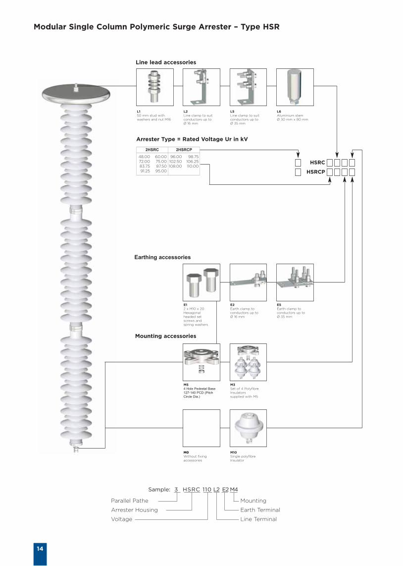
Modular Single Column Polymeric Surge Arrester – Type HSR
14
Sample: 3 HSRC 110 L2 E2 M4
Parallel Pathe
Arrester Housing
Voltage
Mounting
Earth Terminal
Line Terminal
L150 mm stud withwashers and nut M16
L2Line clamp to suitconductors up to Ø 16 mm
L5Line clamp to suitconductors up to Ø 35 mm
L6Aluminium stem Ø 30 mm x 80 mm
Line lead accessories
Earthing accessories
Mounting accessories
M0Without fixingaccessories
M10Single polyfibreInsulator
M3Set of 4 PolyfibreInsulatorssupplied with M5
M54 Hole Pedestal Base
127-140 PCD (Pitch
Circle Dia.)
E2Earth clamp toconductors up toØ 16 mm
E5Earth clamp toconductors up toØ 35 mm
E12 x M10 x 20Hexagonalheaded setscrews andspring washers
2HSRC 2HSRCP
48.00 60.0072.00 75.0083.75 87.5091.25 95.00
96.00 98.75102.50 106.25108.00 110.00
Arrester Type = Rated Voltage Ur in kV
HSRC
HSRCP
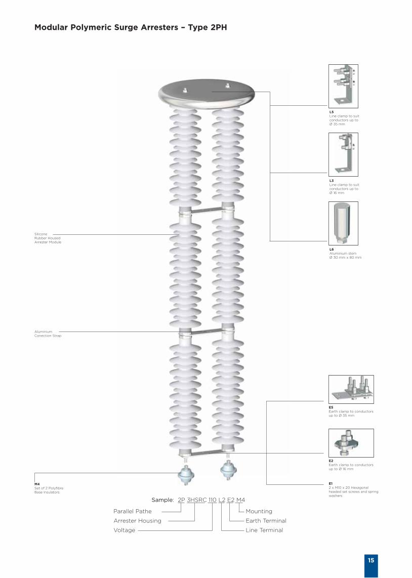
Modular Polymeric Surge Arresters – Type 2PH
15
SiliconeRubber HousedArrester Module
AluminiumConection Strap
E2Earth clamp to conductorsup to Ø 16 mm
E12 x M10 x 20 Hexagonalheaded set screws and springwashers
E5Earth clamp to conductorsup to Ø 35 mm
M4Set of 2 PolyfibreBase Insulators
L5Line clamp to suitconductors up to Ø 35 mm
L3Line clamp to suitconductors up to Ø 16 mm
L6Aluminium stem Ø 30 mm x 80 mm
Sample: 2P 3HSRC 110 L2 E2 M4
Parallel Pathe
Arrester Housing
Voltage
Mounting
Earth Terminal
Line Terminal
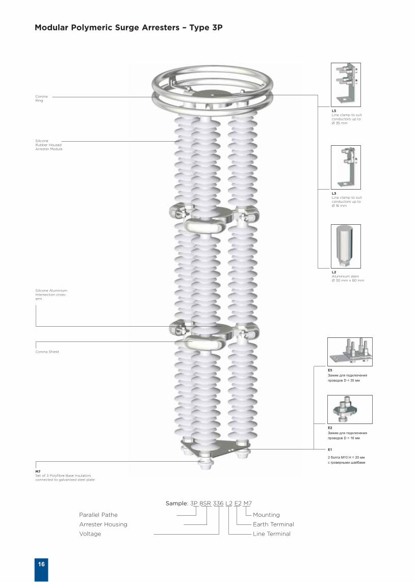
Modular Polymeric Surge Arresters – Type 3P
16
SiliconeRubber HousedArrester Module
Corona Ring
Silicone AluminiumIntersection cross-arm
Corona Shield
M7Set of 3 Polyfibre Base Insulatorsconnected to galvanised steel plate
E2
Зажим для подключения
проводов D < 16 мм
Е1
2 болта М10 H = 20 мм
с гроверными шайбами
E5
Зажим для подключения
проводов D < 35 мм
L5Line clamp to suitconductors up to Ø 35 mm
L3Line clamp to suitconductors up to Ø 16 mm
L2Aluminium stem Ø 30 mm x 80 mm
Sample: 3P 8SR 336 L2 E2 M7
Parallel Pathe
Arrester Housing
Voltage
Mounting
Earth Terminal
Line Terminal
17
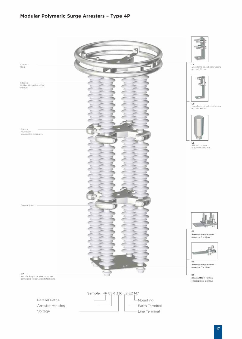
Modular Polymeric Surge Arresters – Type 4P
SiliconeRubber Housed ArresterModule
Silicone Aluminium Intersection cross-arm
Corona Ring
Corona Shield
E2
Зажим для подключения
проводов D < 16 мм
Е1
2 болта М10 H = 20 мм
с гроверными шайбами
E5
Зажим для подключения
проводов D < 35 мм
L5Line clamp to suit conductorsup to Ø 35 mm
L3Line clamp to suit conductorsup to Ø 16 mm
L2Aluminium stem Ø 30 mm x 80 mm
Sample: 4P 8SR 336 L2 E2 M7
M7Set of 4 Polyfibre Base Insulatorsconnected to galvanised steel plate
Parallel Pathe
Arrester Housing
Voltage
Mounting
Earth Terminal
Line Terminal
18
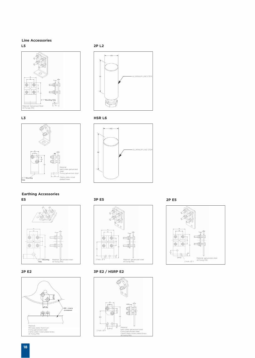
Line Accessories
Earthing Accessories
Ø 17 Mounting
Hole 2 hols Ø 11 Material: galvanized steelAll fixing M10
Material: galvanized steelAll fixing M102 hols Ø 11
2 hols Ø 11
Material: galvanized steelAll fixing M10
Material:back plate galvanised steelFixing galvanized steelClamp plate nickel plated brassAll fixing M10
Material:M2 base plate AluminumFixing galvanized steel Clamp plate nickel plated brass All fixing M10
М2 – плита
основания
E5 3P E5
3P E2 / HSRP E22P E2
2P E5
L3
Material:back plate galvanisedsteelFixing galvanized steel
Clamp plate nickelplated brass
Ø 17 Mounting
Hole
L5
Material: Galvanised SteelAll fixings M10
Ø 17 Mounting Hole
2P L2
ALUMINIUM LINE STEM
HSR L6
ALUMINIUM LINE STEM
19
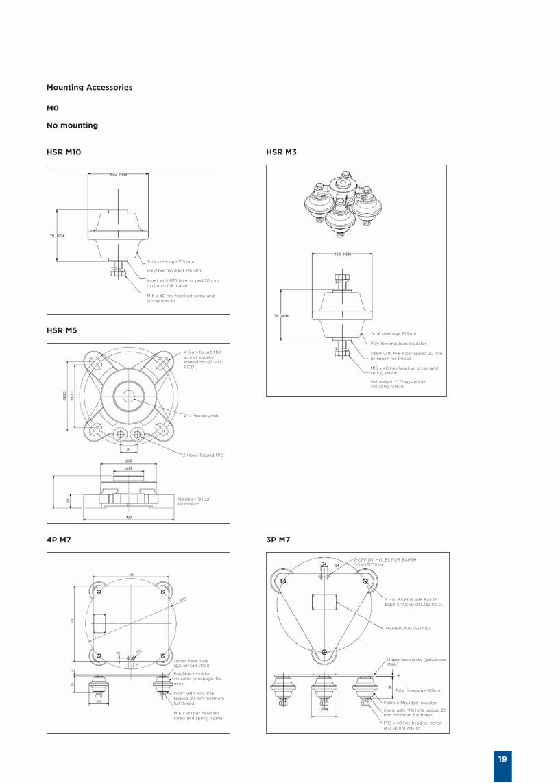
Mounting Accessories
HSR M10
4P M7 3P M7
HSR M5
M0
HSR M3
No mounting
Total creepage 105 mm
Polyfibre moulded insulator
Insert with M16 hole tapped 20 mmminimum full thread
M16 x 40 hex head set screw andspring washer
Total creepage 105 mm
Polyfibre moulded insulator
Insert with M16 hole tapped 20 mmminimum full thread
M16 x 40 hex head set screw andspring washer
Net weight: 0.75 kg approx,including screws
Upper base plate(galvanized steel)
Polyfibre mouldedinsulator (creepage 105mm)
Insert with M16 holetapped 20 mm minimumfull thread
M16 x 40 hex head setscrew and spring washer
4 Slots to suit M12screws equallyspaced on 127-140P.C.D
Ø 17 Mounting Hole
2 Holes Tapped M10
24
6
2-OFF Ø11 HOLES FOR EARTHCONNECTION
3 HOLES FOR M16 BOLTSEQUI-SPACED 0N 332 P.C.D.
NAMEPLATE DETAILS
Polfibre Moulded Insulator
Insert with M16 hole tapped 20mm minimum full thread
M16 x 40 hex head set screwand spring washer
Upper base plate (galvanizedsteel)
Total Creepage 105mm.
Material:- SiliconAluminium
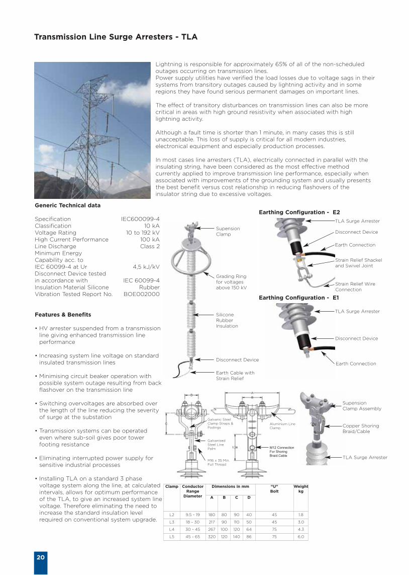
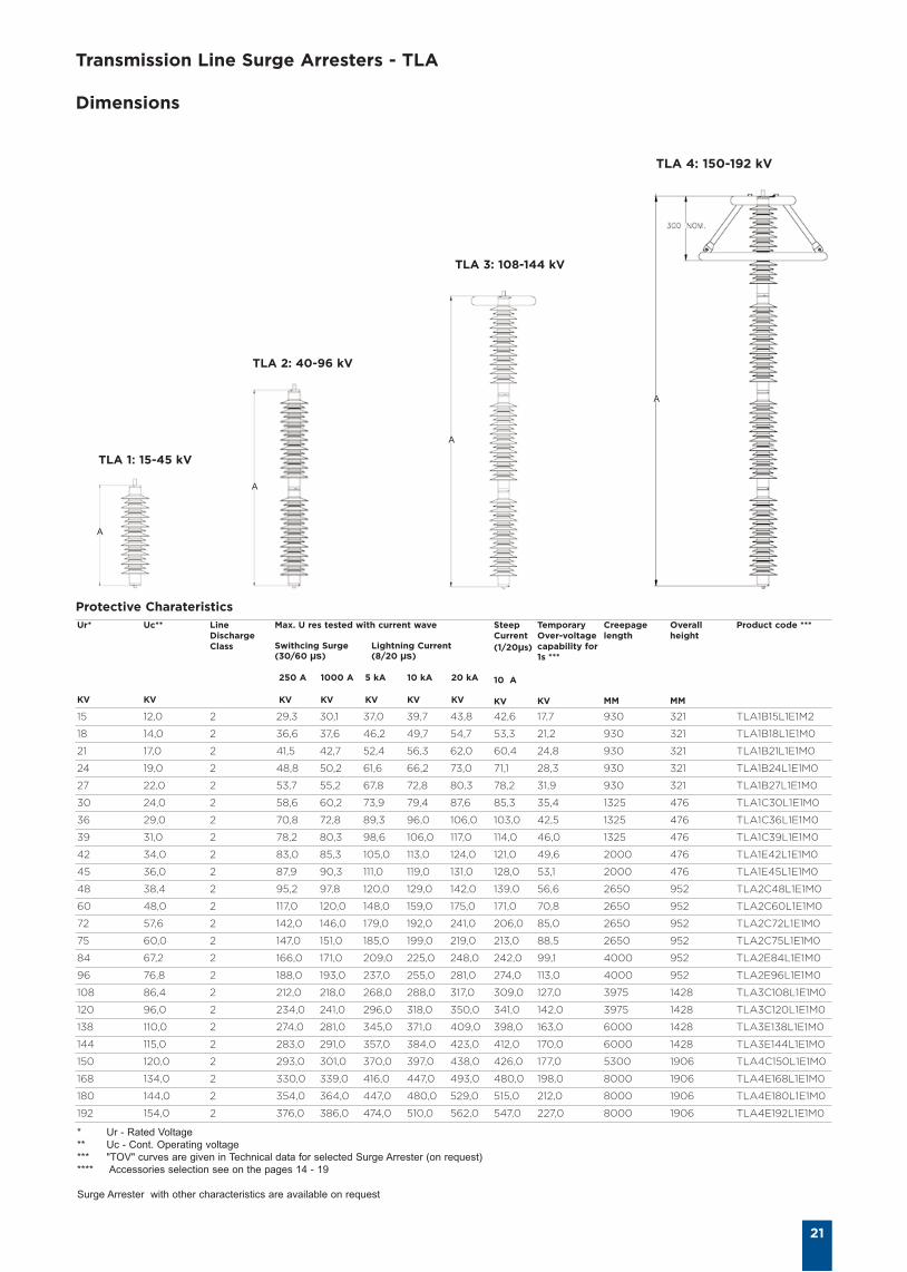
Transmission Line Surge Arresters - TLA
20
Lightning is responsible for approximately 65% of all of the non-scheduledoutages occurring on transmission lines. Power supply utilities have verified the load losses due to voltage sags in theirsystems from transitory outages caused by lightning activity and in someregions they have found serious permanent damages on important lines.
The effect of transitory disturbances on transmission lines can also be morecritical in areas with high ground resistivity when associated with highlightning activity.
Although a fault time is shorter than 1 minute, in many cases this is stillunacceptable. This loss of supply is critical for all modern industries,electronical equipment and especially production processes.
In most cases line arresters (TLA), electrically connected in parallel with theinsulating string, have been considered as the most effective methodcurrently applied to improve transmission line performance, especially whenassociated with improvements of the grounding system and usually presentsthe best benefit versus cost relationship in reducing flashovers of theinsulator string due to excessive voltages.
Generic Technical data
Specification IEC600099-4 Classification 10 kA Voltage Rating 10 to 192 kV High Current Performance 100 kA Line Discharge Class 2 Minimum Energy Capability acc. to IEC 60099-4 at Ur 4,5 kJ/kV Disconnect Device tested in accordance with IEC 60099-4 Insulation Material Silicone Rubber Vibration Tested Report No. BOE002000
Features & Benefits
• HV arrester suspended from a transmissionline giving enhanced transmission lineperformance
• Increasing system line voltage on standardinsulated transmission lines
• Minimising circuit beaker operation withpossible system outage resulting from backflashover on the transmission line
• Switching overvoltages are absorbed overthe length of the line reducing the severityof surge at the substation
• Transmission systems can be operatedeven where sub-soil gives poor towerfooting resistance
• Eliminating interrupted power supply forsensitive industrial processes
• Installing TLA on a standard 3 phasevoltage system along the line, at calculatedintervals, allows for optimum performanceof the TLA, to give an increased system linevoltage. Therefore eliminating the need toincrease the standard insulation levelrequired on conventional system upgrade.
Clamp ConductorRange
Diameter
Dimensions in mm “U”Bolt
Weightkg
A B C D
L2 9.5 - 19 180 80 90 40 45 1.8
L3 18 - 30 217 90 110 50 45 3.0
L4 30 - 45 267 100 120 64 75 4.3
L5 45 - 65 320 120 140 86 75 6.0
Earthing Configuration - E2
Earthing Configuration - E1
TLA Surge Arrester
Disconnect Device
Earth Connection
SupensionClamp Assembly
Copper ShoringBraid/Cable
TLA Surge Arrester
Disconnect Device
Earth Connection
Strain Relief Shackeland Swivel Joint
Strain Relief WireConnection
SupensionClamp
Grading Ringfor voltagesabove 150 kV
SiliconeRubberInsulation
Disconnect Device
Earth Cable withStrain Relief
TLA Surge Arrester
Galvanic SteelClamp Straps &Podings
GalvanisedSteel LinePalm
M16 x 35 Min.Full Thread
Aluminium LineClamp
M12 Connection
For Shoring
Braid.Cable
Transmission Line Surge Arresters - TLA
Dimensions
21
TLA 1: 15-45 kV
TLA 2: 40-96 kV
TLA 3: 108-144 kV
TLA 4: 150-192 kV
Ur*
KV
Uc**
KV
LineDischargeClass
Max. U res tested with current wave
Swithcing Surge Lightning Current(30/60 µs) (8/20 µs)
250 A 1000 A 5 kA 10 kA 20 kA
KV KV KV KV KV
SteepCurrent(1/20µs)
10 A
KV
TemporaryOver-voltagecapability for1s ***
KV
Creepagelength
MM
Overall height
MM
Product code ***
15 12,0 2 29,3 30,1 37,0 39,7 43,8 42,6 17,7 930 321 TLA1B15L1E1M2
18 14,0 2 36,6 37,6 46,2 49,7 54,7 53,3 21,2 930 321 TLA1B18L1E1M0
21 17,0 2 41,5 42,7 52,4 56,3 62,0 60,4 24,8 930 321 TLA1B21L1E1M0
24 19,0 2 48,8 50,2 61,6 66,2 73,0 71,1 28,3 930 321 TLA1B24L1E1M0
27 22,0 2 53,7 55,2 67,8 72,8 80,3 78,2 31,9 930 321 TLA1B27L1E1M0
30 24,0 2 58,6 60,2 73,9 79,4 87,6 85,3 35,4 1325 476 TLA1C30L1E1M0
36 29,0 2 70,8 72,8 89,3 96,0 106,0 103,0 42,5 1325 476 TLA1C36L1E1M0
39 31,0 2 78,2 80,3 98,6 106,0 117,0 114,0 46,0 1325 476 TLA1C39L1E1M0
42 34,0 2 83,0 85,3 105,0 113,0 124,0 121,0 49,6 2000 476 TLA1E42L1E1M0
45 36,0 2 87,9 90,3 111,0 119,0 131,0 128,0 53,1 2000 476 TLA1E45L1E1M0
48 38,4 2 95,2 97,8 120,0 129,0 142,0 139,0 56,6 2650 952 TLA2C48L1E1M0
60 48,0 2 117,0 120,0 148,0 159,0 175,0 171,0 70,8 2650 952 TLA2C60L1E1M0
72 57,6 2 142,0 146,0 179,0 192,0 241,0 206,0 85,0 2650 952 TLA2C72L1E1M0
75 60,0 2 147,0 151,0 185,0 199,0 219,0 213,0 88,5 2650 952 TLA2C75L1E1M0
84 67,2 2 166,0 171,0 209,0 225,0 248,0 242,0 99,1 4000 952 TLA2E84L1E1M0
96 76,8 2 188,0 193,0 237,0 255,0 281,0 274,0 113,0 4000 952 TLA2E96L1E1M0
108 86,4 2 212,0 218,0 268,0 288,0 317,0 309,0 127,0 3975 1428 TLA3C108L1E1M0
120 96,0 2 234,0 241,0 296,0 318,0 350,0 341,0 142,0 3975 1428 TLA3C120L1E1M0
138 110,0 2 274,0 281,0 345,0 371,0 409,0 398,0 163,0 6000 1428 TLA3E138L1E1M0
144 115,0 2 283,0 291,0 357,0 384,0 423,0 412,0 170,0 6000 1428 TLA3E144L1E1M0
150 120,0 2 293,0 301,0 370,0 397,0 438,0 426,0 177,0 5300 1906 TLA4C150L1E1M0
168 134,0 2 330,0 339,0 416,0 447,0 493,0 480,0 198,0 8000 1906 TLA4E168L1E1M0
180 144,0 2 354,0 364,0 447,0 480,0 529,0 515,0 212,0 8000 1906 TLA4E180L1E1M0
192 154,0 2 376,0 386,0 474,0 510,0 562,0 547,0 227,0 8000 1906 TLA4E192L1E1M0
A
A
A
A
* Ur - Rated Voltage
** Uc - Cont. Operating voltage
*** "TOV" curves are given in Technical data for selected Surge Arrester (on request)
**** Accessories selection see on the pages 14 - 19
Surge Arrester with other characteristics are available on request
Protective Charateristics
22
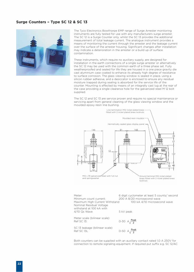
Surge Counters – Type SC 12 & SC 13
The Tyco Electronics Bowthorpe EMP range of Surge Arrester monitoringinstruments are fully tested for use with any manufacturers surge arrester.The SC 12 is a Surge Counter only, whilst the SC 13 provides the additionalmeasurement of total leakage current. The analogue instrument provides ameans of monitoring the current through the arrester and the leakage currentover the surface of the arrester housing. Significant changes after installationmay indicate a deterioration in the arrester or a build up of surfacecontamination.
These instruments, which require no auxiliary supply, are designed forinstallation in the earth connections of a single surge arrester or alternativelythe SC 12 may be used with the common earth of a three phase set. Fullyweatherproofed and sealed for life they are housed in a one piece gravity diecast aluminium case coated to enhance its already high degree of resistanceto surface corrosion. The glass viewing window is sealed in place, using asilicon rubber adhesive, and a desiccator is enclosed to ensure any residualmoisture trapped during sealing is absorbed for the service life of thecounter. Mounting is effected by means of an integrally cast lug at the rear ofthe case providing a single clearance hole for the galvanized steel M 12 boltsupplied.
The SC 12 and SC 13 are service proven and require no special maintenance orservicing apart from general cleaning of the glass viewing window and themoulded epoxy resin line bushing.
Meter: 6 digit cyclometer at least 5 counts/ secondMinimum count current: 200 A 8/20 microsecond wave Maximum High Current Withstand 100 kA 4/10 microsecond wave Nominal Residual Voltage withstand at 100 kA with 4/10 μs Wave 5 kV peak
Meter scale (bilinear scale) Ref SC 13: 0-30 A
SC 13 leakage (bilinear scale)Ref SC 13L 0-50 A
Both counters can be supplied with an auxiliary contact rated 1,0 A 250V forconnection to remote signaling equipment. If required put suffix e.g. SC 12/AC
M12 x 35 galvanized steel with full nutand springwasher
Ground terminal M12 nickel platedbrass fitted with 2 nickel plated brasslocknuts
Line termination M12 nickel plated brassfitted with 2 nickel plated brass locknuts
Moulded resin insulator
Hermetically sealed glass display panel

23
Tyco Electronics total commitment to quality
Even the best technology must bebacked up by a thorough andconsistentquality assurance program.At Tyco Electronics, we subject everyproduct to an extensive qualitycontrol regimen which includes thefollowing procedures:
• At every production stage,beginning with the raw materialsand continuingthrough to thepackaged product, the QC lab testsall physical andelectricalcharacteristics which caninfluence quality.
• By means of lot numbers theQuality Assurance Program ensurestraceabilitybackwards all the way tothe details of the compound batchtest reports.
• We carry out requalification testingon a regular basis.
Quality assurance at Tyco Electronicsis not a static, but rather a constantlyimproving process directed towardsour goals: complete customersatisfaction.
The Tyco Electronics Energy Divisionarrester manufacturing sites areaccreditedto ISO 9001. Our vendorroutine tests and internal incominginspection confirm performance of allcritical components used in theassembly of our arresters.
Automated routine test facilityforMetal-Oxide Surge Arresters inthemanufacturing area
24
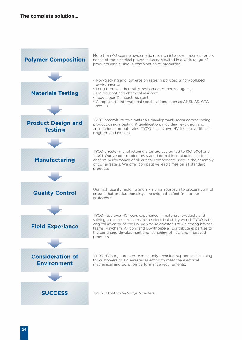
The complete solution...
Polymer Composition
Materials Testing
Product Design andTesting
Manufacturing
Quality Control
Field Experiance
Consideration ofEnvironment
SUCCESS
More than 40 years of systematic research into new materials for theneeds of the electrical power industry resulted in a wide range ofproducts with a unique combination of properties.
• Non-tracking and low erosion rates in polluted & non-pollutedenvironments
• Long term weatherability, resistance to thermal ageing• UV resistant and chemical resistant• Tough, tear & impact resistant• Compliant to International specifications, such as ANSI, AS, CEA
and IEC
TYCO controls its own materials development, some compounding,product design, testing & qualification, moulding, extrusion andapplications through sales. TYCO has its own HV testing facilities inBrighton and Munich.
TYCO arrester manufacturing sites are accredited to ISO 9001 and14001. Our vendor routine tests and internal incoming inspectionconfirm performance of all critical components used in the assemblyof our arresters. We offer competitive lead times on all standardproducts.
Our high quality molding and six sigma approach to process controlensuresthat product housings are shipped defect free to ourcustomers.
TYCO have over 40 years experience in materials, products andsolving customer problems in the electrical utility world. TYCO is theoriginal inventor of the HV polymeric arrester. TYCOs strong brandsteams, Raychem, Axicom and Bowthorpe all contribute expertise tothe continued development and launching of new and improvedproducts.
TYCO HV surge arrester team supply technical support and trainingfor customers to aid arrester selection to meet the electrical,mechanical and pollution performance requirements.
TRUST Bowthorpe Surge Arresters.

Tyco Electronics Raychem GmbH Energy DivisionFinsinger Feld 1, 85521Ottobrunn/Munich, Germany
Phone: + 49 89 6089-521 Fax: + 49 89 6089-741
http://energy.tycoelectronics.com
©Tyco E
lectr
onic
s E
PP
1386 4
/08
RUSSIA
Tyco Electronics Raychem GmbH, Energy Division127083 Moscow
Mishina str. 56
bld.2
Tel.: +7 495-790 790 2-200
Fax: +7 495-721 1892
192007 St.-Petersburg
Tambovskaya str. 12
Office 52-53
Tel.: +7 812-718 8167
Fax: +7 812-718 8176
630054 Novosibirsk
3 per. Krasheninnikova, 3
Office 104
Tel.: +7 383-355 9992
Fax: +7 383-355 9991
443096 Samara
Michurina str. 52
Office 315
Tel./Fax: +7 846-266 9514
620085 Ekaterinburg
Ferganskaya ul. 16
Office 209
Tel./Fax: +7 343-297 1829
680000 Khabarovsk
Murieva-Amurskogo str. 44
Office 313
Tel./Fax: +7 421-245 1154
344023 Rostov-na-Donu
Lenina str. 118a
Tel. /Fax: +7 863-293 0739
394016 Voronezh
Moskovsky Prospect 53
Office 202
Tel./Fax: +7 473-239 2277
UKRAINE KAZAKHSTAN
Tyco Electronics Raychem GmbH, Energy Division Tyco Electronics Raychem GmbH, Energy Division04050 Kiev
13, Pimonenko Str., 7A section / 11
Tel.: +380 44-206 2266
Fax: +380 44-206 2268
883023 Donetsk
16 – A Labutenko Str., office 123
ТTel./Fax: +380 62-332 3644
050004 Almaty
Naurizbay batyr street 17
Office 215
Tel.: +7 727-244 5875
Fax: +7 727-244 5877
«Tyco Electronics Raychem GmbH» Representative Offices in CIS Countries
ARMENIA AZERBAIJAN BELARUS GEORGIA
YERENERGO CJSC
375001 Yerevan
11 Toumanyan str., office 7
Tel.: +374 10-542 122
Fax: +374 10-582 060
Alifagha ALKHANOV
370010 Baku
Rafili str. 11-18
Tel./Fax: +994 12-493 4226
Vyacheslav DEMICHEV
220050 Minsk
K. Marksa 21-39
Tel./Fax: +375 17-226 0333
Nodar MGEBRISHVILI
Tbilisi 0179
Radiani st. 19
Тел.: +995 99-562 791
Факс: +995 32-230 392
MOLDOVA MONGOLIA TAJIKISTAN TURKMENISTAN
Igor BEIU
2068 Chişinău
Str. Miron Costin, nr.19, bl.5, apt.63
Tel./Fax.: +373 22-322 155
Ulziikhishig BAYASGALAN
Ulaanbaatar
Baga-toiruu-35, Sukhe-baatar District
Bld. Hatansuih LLC, Room 101
Tel./Fax.: + 976 11-320 653
Akmal KAMIROV
734024 Dushanbe
Nazarshoev street 143
Tel: +992 37-881 3106
Fax: + 992 37-227 1659
Тимур СултанмурадовTimur
SULTANMURADOV
744007 Ashgabat
A. Berdieva 25-307
Tel./Fax: +99 312-326 826
UZBEKISTAN KYRGYZSTAN
Iskander KAMILOV
100000 Tashkent
Merzo-Ulugbeksky D-t
24 Akmal Ikramov st.
Tel: +998 71-152 6256
Tel. +998 71-137 5250
Fax: +998 71-137 5251
is served by “Tyco Electronics Raychem
GmbH” representative in Uzbekistan
«Tyco Electronics Raychem GmbH» Offices in CIS Countries
All of the above information, including drawings, illustrations and graphic designs, reflects our present understanding and is to the best of our knowledge and belief correctand reliable. Users, however, should independently evaluate the suitability of each product for the desired application. Under no circumstances does this constitute anassurance of any particular quality or performance. Such an assurance is only provided in the context of our product specifications or explicit contractual arrangements.Our liability for these products is set forth in our standard terms and conditions of sale. Raychem, SIMEL TE logo and Tyco Electronics are trademarks.