Embed Size (px)
Citation preview
Product Data Sheet00813-0100-4026, Rev FB
February 2008 Rosemount 5400 Series
Two-wire Radar Level Transmitter
The Rosemount 5400 Series is a reliable 2-wire
radar level transmitter for liquids and slurries,
designed for outstanding performance in a wide
range of applications and process conditions. It
measures level directly and is unaffected by most
fluid property changes, including temperature,
pressure, vapor gas mixture, density, turbulence,
bubbling/boiling, dielectric, pH, viscosity,
crystallization, etc.
• Innovative design. Best-in-class performance
• Non-contacting, making it virtually unaffected
by process conditions
• No moving parts, means little or no
maintenance
• Application flexibility with full range of
antennas, and two models 5402 (26 GHz) and
5401 (6 GHz)
• Less affected by coating with Condensation
Resistant Antenna
• Reduced echoes from obstacles / tank walls
with Circular Polarization
• Powerful, easy-to-use configuration tool
with“Measure-and-Learn” function
Content
www.rosemount.com
Innovative Measurement Technologies for a Better Bottom Line. . . . . . . . . . . . . . . . . . . . . . . .page 2
Reliable Measurements through Advanced Surface Tracking Capability . . . . . . . . . . . . . . . . .page 5
System Integration. . . . . . . . . . . . . . . . . . . . . . . . . . . . . . . . . . . . . . . . . . . . . . . . . . . . . . . . . . .page 6
Transmitter and Antenna Overview . . . . . . . . . . . . . . . . . . . . . . . . . . . . . . . . . . . . . . . . . . . . . .page 8
Measuring Range . . . . . . . . . . . . . . . . . . . . . . . . . . . . . . . . . . . . . . . . . . . . . . . . . . . . . . . . . .page 11
Mechanical Mounting Recommendations . . . . . . . . . . . . . . . . . . . . . . . . . . . . . . . . . . . . . . . .page 12
Specifications. . . . . . . . . . . . . . . . . . . . . . . . . . . . . . . . . . . . . . . . . . . . . . . . . . . . . . . . . . . . . .page 15
Product Certifications. . . . . . . . . . . . . . . . . . . . . . . . . . . . . . . . . . . . . . . . . . . . . . . . . . . . . . . .page 18
Dimensional Drawings and Mechanical Properties . . . . . . . . . . . . . . . . . . . . . . . . . . . . . . . . .page 21
Ordering Information . . . . . . . . . . . . . . . . . . . . . . . . . . . . . . . . . . . . . . . . . . . . . . . . . . . . . . . .page 28
Application & Configuration Data Sheet. . . . . . . . . . . . . . . . . . . . . . . . . . . . . . . . . . . . . . . . . .page 34
Product Data Sheet00813-0100-4026, Rev FB
February 2008Rosemount 5400 Series
Innovative Measurement Technologies for a Better Bottom
Line
The 5400 Series transmitter is used for level
measurements on liquids and slurries with various
temperatures, pressures and vapor gas mixtures.
Because of its advanced surface tracking capability,
the transmitter can detect and evaluate all echoes
within the tank.
The Rosemount 5400 Series is easily configured for
a wide range of applications and process conditions.
In addition, it incorporates advanced signal
processing and smart echo tracking features.
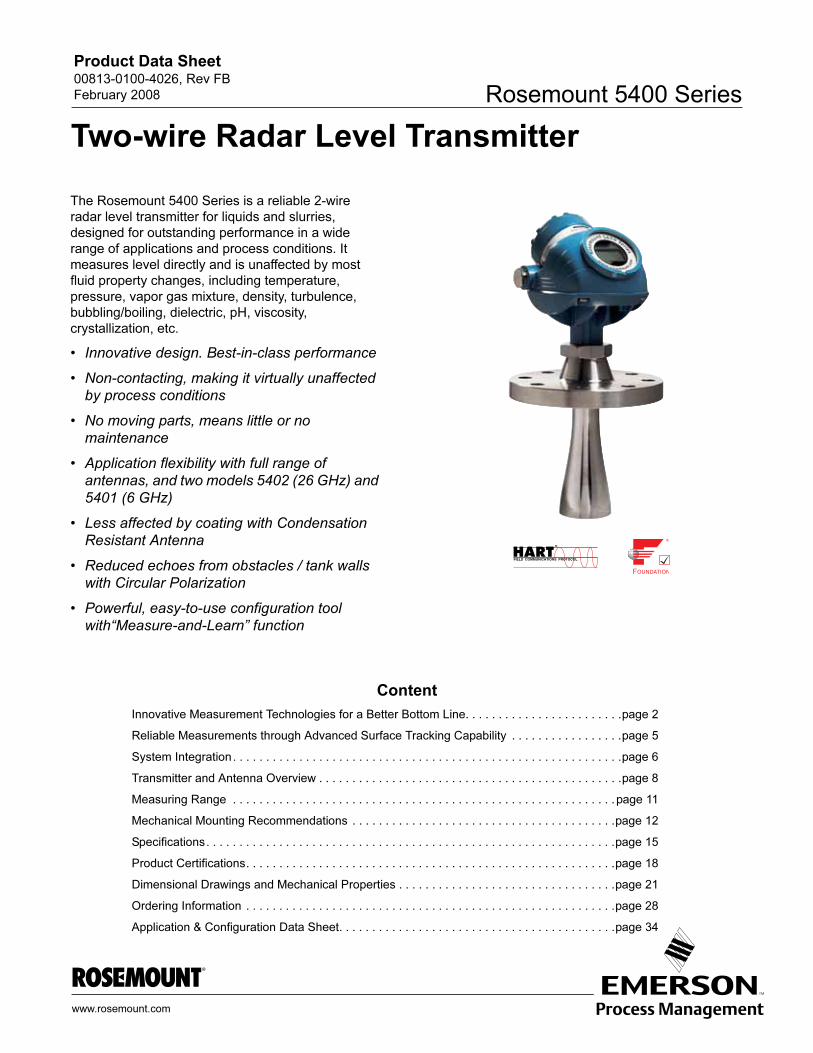
MEASUREMENT PRINCIPLE
The distance to the surface is measured by short
radar pulses, which are transmitted from the antenna
at the tank top.
When a radar pulse reaches a media with a different
dielectric constant, part of the energy is reflected
back to the transmitter. The time difference between
the transmitted and the reflected pulse is proportional
to the distance, from which the level, volume and
level rate, are calculated.
MODELS
The 5400 Series consists of two models:
• Rosemount 5401, Low Frequency Transmitter (~ 6 GHz).
• Rosemount 5402, High Frequency Transmitter (~ 26 GHz).
The availability of two frequencies allows the user to
choose the model that best fit the installation and
process conditions, with the 5402 being the preferred
choice for most applications.
Le
ve
l
Time
Dis
tan
ce
Ta
nk
He
igh
t
The 5401 transmitter is
used in applications with
some extreme process
conditions.
The 5402 transmitter is the
preferred choice in most
applications because its
narrow radar beam offers
greater mounting flexibility.
2
Product Data Sheet00813-0100-4026, Rev FB
February 2008 Rosemount 5400 Series
APPLICATION EXAMPLES FOR THE 5400 SERIES RADAR LEVEL TRANSMITTER
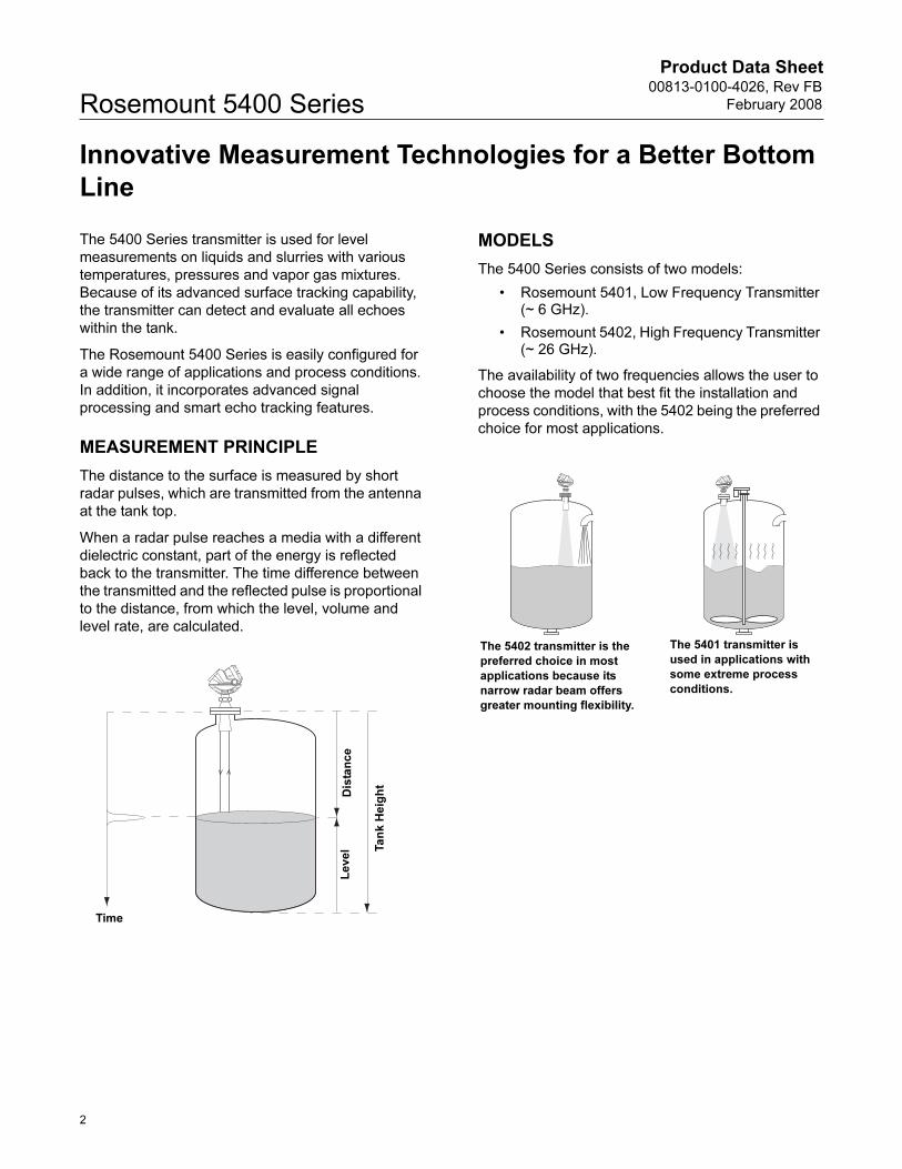
Tanks, vessels, and containers with calm surfaces
Non-contacting radar can also be used in less
challenging applications, such as storage and buffer
tanks:
• It is easy to mount, maintenance-free, and highly accurate
• Gives precise monitoring and control of the process
Overfill and underfill detection
The 5400 Series can be advantageous in risk reduction
systems:
• Continuous measurement may reduce or simplify proof-tests
• Multiple 5400’s can be used in the same tank
Corrosives
Radar measurement is ideal for most corrosive products,
such as caustics, acids, solvents and many other
chemicals:
• Not in contact with process product
• Wide material offering such as PTFE, Hastelloy and Monel
• Works well also in non-metallic tanks
Sticky, viscous and crystallizing products
The best-in-class 5400 Series provides an accurate and
reliable level reading with difficult products, such as
resins and adhesives:
• Non-contacting is best practice
• Almost unaffected by coating and build-up due to the uniquely designed condensation resistant antennas
Sludges and slurries
Applications like mud, pulp-stock and lime slurries are
ideal for non-contacting measurement:
• Immune to splashing and solids content
• Unaffected by density changes
• No re-calibration, no or little maintenace
3
Product Data Sheet00813-0100-4026, Rev FB
February 2008Rosemount 5400 Series
For more information on which model and antenna to use for the applications above, see “Transmitter and Antenna
Overview” on page 8 and “Measuring Range” on page 11, or contact your local Emerson Process Management
representative.
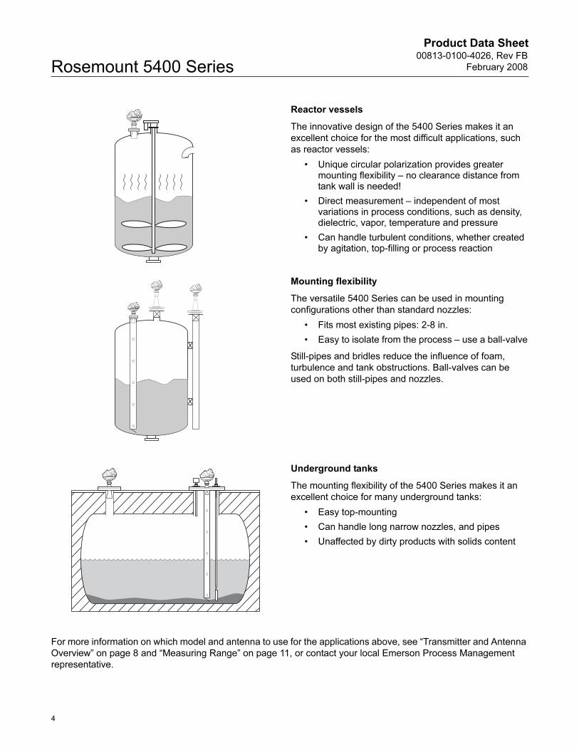
Reactor vessels
The innovative design of the 5400 Series makes it an
excellent choice for the most difficult applications, such
as reactor vessels:
• Unique circular polarization provides greater mounting flexibility – no clearance distance from tank wall is needed!
• Direct measurement – independent of most variations in process conditions, such as density, dielectric, vapor, temperature and pressure
• Can handle turbulent conditions, whether created by agitation, top-filling or process reaction
Mounting flexibility
The versatile 5400 Series can be used in mounting
configurations other than standard nozzles:
• Fits most existing pipes: 2-8 in.
• Easy to isolate from the process – use a ball-valve
Still-pipes and bridles reduce the influence of foam,
turbulence and tank obstructions. Ball-valves can be
used on both still-pipes and nozzles.
Underground tanks
The mounting flexibility of the 5400 Series makes it an
excellent choice for many underground tanks:
• Easy top-mounting
• Can handle long narrow nozzles, and pipes
• Unaffected by dirty products with solids content
4
Product Data Sheet00813-0100-4026, Rev FB
February 2008 Rosemount 5400 Series
Reliable Measurements through Advanced Surface
Tracking Capability
Different process conditions, such as the tank
atmosphere, foam, turbulence and products with low
dielectric constants, will decrease the returned signal
and the radar transmitter may lose track of the
surface. It is important that the transmitter can detect
very weak signals.
The Rosemount 5400 Series transmitter incorporates
several new innovations to provide the best possible
surface tracking capability. These features contribute
to more reliable measurements and better
performance than with standard 2-wire transmitters.
DUAL PORT TECHNOLOGY
Dual Port Technology, two ports for transmitting and
receiving signals, reduces noise. Even with a weak
returned signal, the transmitter will be able to detect
it.
A transmitter with Dual Port Technology can receive
75% less reflected energy than a standard 2-wire
transmitter, and still have equal or better surface
tracking capability.
Standard 2-wire radar level transmitters only use one
port on the microwave generation module for
sending and receiving signals, which introduces
significant losses in the microwave generation.
CONDENSATION RESISTANT ANTENNA
The tank seal is the part of the waveguide that
protects the transmitter from the process
atmosphere. Rosemount 5400 Series has a larger
protective surface towards the tank, making the
transmitter less sensitive to dirt and condensation.
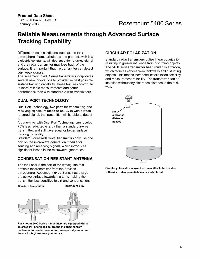
CIRCULAR POLARIZATION
Standard radar transmitters utilize linear polarization
resulting in greater influence from disturbing objects.
The 5400 Series transmitter has circular polarization,
which reduces echoes from tank walls and disturbing
objects. This means increased installallation flexibility
and measurement reliability. The transmitter can be
installed without any clearance distance to the tank
wall.
Circular polarization allows the transmitter to be installed
without any clearance distance to the tank wall.
Rosemount 5400 Series transmitters are equipped with an
enlarged PTFE tank seal to protect the antenna from
contamination and condensation, an especially important
feature for high frequency antennas.
Standard Transmitter Rosemount 5402
No
clearance
distance
needed
5
Product Data Sheet00813-0100-4026, Rev FB
February 2008Rosemount 5400 Series
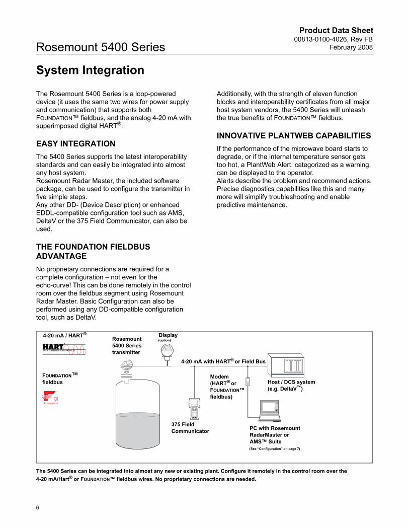
System Integration
The Rosemount 5400 Series is a loop-powered
device (it uses the same two wires for power supply
and communication) that supports both
FOUNDATION™ fieldbus, and the analog 4-20 mA with
superimposed digital HART®.
EASY INTEGRATION
The 5400 Series supports the latest interoperability
standards and can easily be integrated into almost
any host system.
Rosemount Radar Master, the included software
package, can be used to configure the transmitter in
five simple steps.
Any other DD- (Device Description) or enhanced
EDDL-compatible configuration tool such as AMS,
DeltaV or the 375 Field Communicator, can also be
used.
THE FOUNDATION FIELDBUS ADVANTAGE
No proprietary connections are required for a
complete configuration – not even for the
echo-curve! This can be done remotely in the control
room over the fieldbus segment using Rosemount
Radar Master. Basic Configuration can also be
performed using any DD-compatible configuration
tool, such as DeltaV.
Additionally, with the strength of eleven function
blocks and interoperability certificates from all major
host system vendors, the 5400 Series will unleash
the true benefits of FOUNDATION™ fieldbus.
INNOVATIVE PLANTWEB CAPABILITIES
If the performance of the microwave board starts to
degrade, or if the internal temperature sensor gets
too hot, a PlantWeb Alert, categorized as a warning,
can be displayed to the operator.
Alerts describe the problem and recommend actions.
Precise diagnostics capabilities like this and many
more will simplify troubleshooting and enable
predictive maintenance.
The 5400 Series can be integrated into almost any new or existing plant. Configure it remotely in the control room over the
4-20 mA/Hart® or FOUNDATION™ fieldbus wires. No proprietary connections are needed.
Rosemount
5400 Series
transmitter
Display
Host / DCS system
(e.g. DeltaV™)
Modem
(HART® or
FOUNDATION™
fieldbus)
PC with Rosemount
RadarMaster or
AMS™ Suite
4-20 mA / HART®
375 Field
Communicator
(See “Configuration” on page 7)
4-20 mA with HART® or Field Bus
FOUNDATION™
fieldbus
(option)
6
Product Data Sheet00813-0100-4026, Rev FB
February 2008 Rosemount 5400 Series
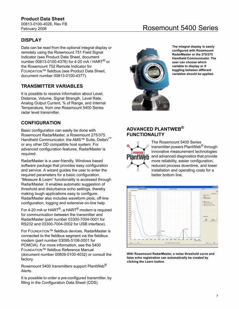
DISPLAY
Data can be read from the optional integral display or
remotely using the Rosemount 751 Field Signal
Indicator (see Product Data Sheet, document
number 00813-0100-4378) for 4-20 mA / HART® or
the Rosemount 752 Remote Indicator for
FOUNDATION™ fieldbus (see Product Data Sheet,
document number 00813-0100-4377).
TRANSMITTER VARIABLES
It is possible to receive information about Level,
Distance, Volume, Signal Strength, Level Rate,
Analog Output Current, % of Range, and Internal
Temperature, from one Rosemount 5400 Series
radar level transmitter.
CONFIGURATION
Basic configuration can easily be done with
Rosemount RadarMaster, a Rosemount 275/375
Handheld Communicator, the AMS™ Suite, DeltaV™
or any other DD compatible host system. For
advanced configuration features, RadarMaster is
required.
RadarMaster is a user-friendly, Windows based
software package that provides easy configuration
and service. A wizard guides the user to enter the
required parameters for a basic configuration.
“Measure & Learn” functionality is accessed through
RadarMaster. It enables automatic suggestion of
threshold and disturbance echo settings, thereby
making tough applications easy to configure.
RadarMaster also includes waveform plots, off-line
configuration, logging and extensive on-line help.
For 4-20 mA or HART®, a HART® modem is required
for communication between the transmitter and
RadarMaster (part number 03300-7004-0001 for
RS232 and 03300-7004-0002 for USB interface).
For FOUNDATION™ fieldbus devices, RadarMaster is
connected to the fieldbus segment via the fieldbus
modem (part number 03095-5108-0001 for
PCMCIA). For more information, see the 5400
FOUNDATION™ fieldbus Reference Manual
(document number 00809-0100-4032) or consult the
factory.
Rosemount 5400 transmitters support PlantWeb®
Alerts.
It is possible to order a pre-configured transmitter, by
filling in the Configuration Data Sheet (CDS).
ADVANCED PLANTWEB® FUNCTIONALITY
The Rosemount 5400 Series
transmitter powers PlantWeb® through
innovative measurement technologies
and advanced diagnostics that provide
more reliability, easier configuration,
reduced process downtime, and lower
installation and operating costs for a
better bottom line.
The integral display is easily
configured with Rosemount
RadarMaster or the 275/375
Handheld Communicator. The
user can choose which
variable to display or if
toggling between different
variables should be applied.
With Rosemount RadarMaster, a noise threshold curve and
false echo registration can automatically be created by
clicking the Learn button.
7
Product Data Sheet00813-0100-4026, Rev FB
February 2008Rosemount 5400 Series
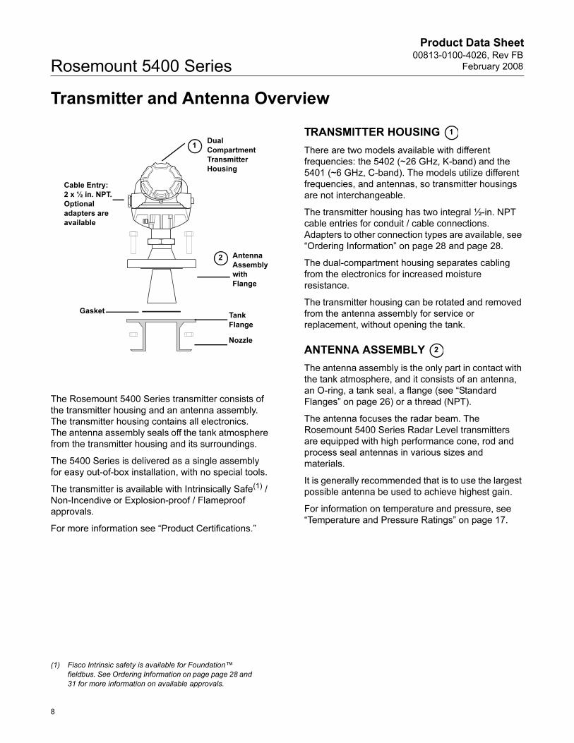
Transmitter and Antenna Overview
The Rosemount 5400 Series transmitter consists of
the transmitter housing and an antenna assembly.
The transmitter housing contains all electronics.
The antenna assembly seals off the tank atmosphere
from the transmitter housing and its surroundings.
The 5400 Series is delivered as a single assembly
for easy out-of-box installation, with no special tools.
The transmitter is available with Intrinsically Safe(1) /
Non-Incendive or Explosion-proof / Flameproof
approvals.
For more information see “Product Certifications.”
TRANSMITTER HOUSING
There are two models available with different
frequencies: the 5402 (~26 GHz, K-band) and the
5401 (~6 GHz, C-band). The models utilize different
frequencies, and antennas, so transmitter housings
are not interchangeable.
The transmitter housing has two integral ½-in. NPT
cable entries for conduit / cable connections.
Adapters to other connection types are available, see
“Ordering Information” on page 28 and page 28.
The dual-compartment housing separates cabling
from the electronics for increased moisture
resistance.
The transmitter housing can be rotated and removed
from the antenna assembly for service or
replacement, without opening the tank.
ANTENNA ASSEMBLY
The antenna assembly is the only part in contact with
the tank atmosphere, and it consists of an antenna,
an O-ring, a tank seal, a flange (see “Standard
Flanges” on page 26) or a thread (NPT).
The antenna focuses the radar beam. The
Rosemount 5400 Series Radar Level transmitters
are equipped with high performance cone, rod and
process seal antennas in various sizes and
materials.
It is generally recommended that is to use the largest
possible antenna be used to achieve highest gain.
For information on temperature and pressure, see
“Temperature and Pressure Ratings” on page 17.
(1) Fisco Intrinsic safety is available for Foundation™
fieldbus. See Ordering Information on page page 28 and
31 for more information on available approvals.
Cable Entry:
2 x ½ in. NPT.
Optional
adapters are
available
1
Antenna
Assembly
with
Flange
Dual
Compartment
Transmitter
Housing
2
Tank
Flange
Nozzle
Gasket
1
2
8
Product Data Sheet00813-0100-4026, Rev FB
February 2008 Rosemount 5400 Series
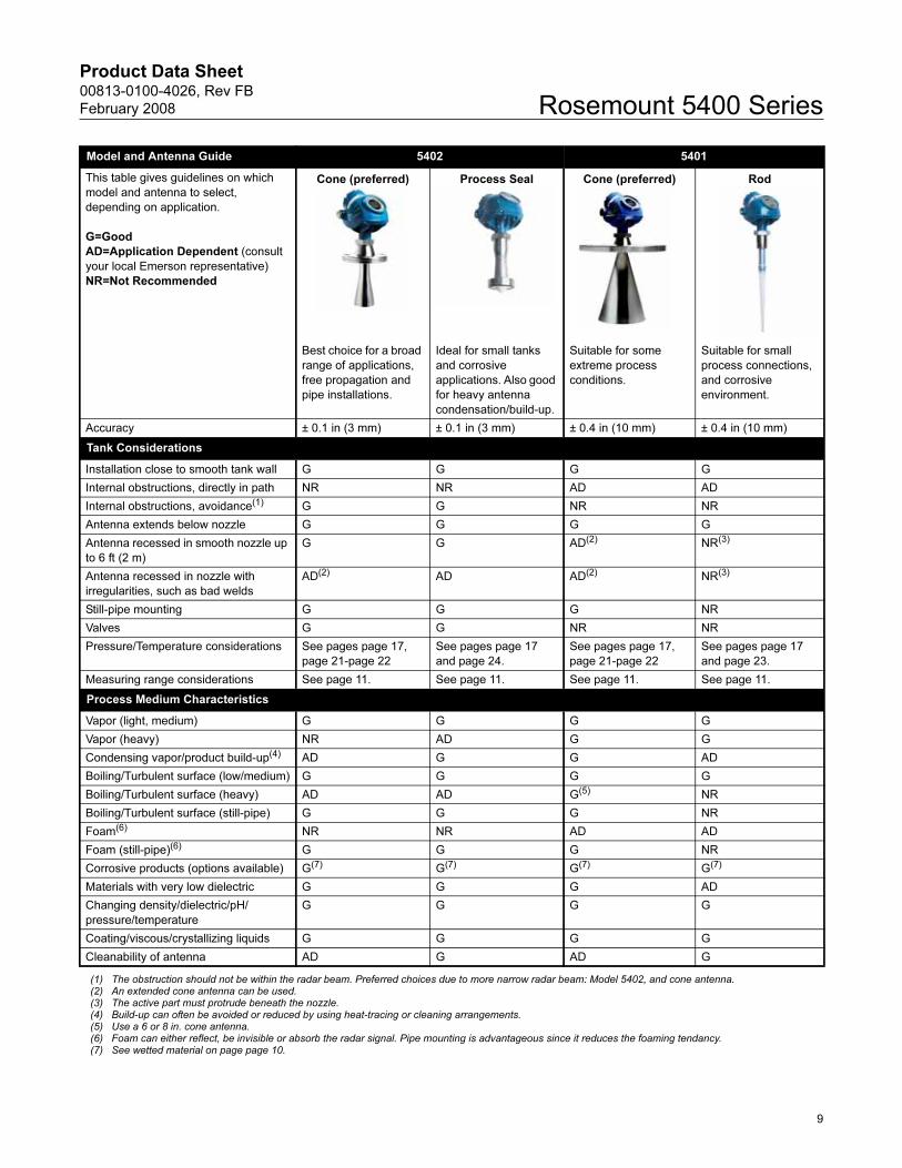
Model and Antenna Guide 5402 5401
This table gives guidelines on which
model and antenna to select,
depending on application.
G=Good
AD=Application Dependent (consult
your local Emerson representative)
NR=Not Recommended
Cone (preferred) Process Seal Cone (preferred) Rod
Best choice for a broad
range of applications,
free propagation and
pipe installations.
Ideal for small tanks
and corrosive
applications. Also good
for heavy antenna
condensation/build-up.
Suitable for some
extreme process
conditions.
Suitable for small
process connections,
and corrosive
environment.
Accuracy ± 0.1 in (3 mm) ± 0.1 in (3 mm) ± 0.4 in (10 mm) ± 0.4 in (10 mm)
Tank Considerations
Installation close to smooth tank wall G G G G
Internal obstructions, directly in path NR NR AD AD
Internal obstructions, avoidance(1) G G NR NR
Antenna extends below nozzle G G G G
Antenna recessed in smooth nozzle up
to 6 ft (2 m)
G G AD(2) NR(3)
Antenna recessed in nozzle with
irregularities, such as bad welds
AD(2) AD AD(2) NR(3)
Still-pipe mounting G G G NR
Valves G G NR NR
Pressure/Temperature considerations See pages page 17,
page 21-page 22
See pages page 17
and page 24.
See pages page 17,
page 21-page 22
See pages page 17
and page 23.
Measuring range considerations See page 11. See page 11. See page 11. See page 11.
Process Medium Characteristics
Vapor (light, medium) G G G G
Vapor (heavy) NR AD G G
Condensing vapor/product build-up(4) AD G G AD
Boiling/Turbulent surface (low/medium) G G G G
Boiling/Turbulent surface (heavy) AD AD G(5) NR
Boiling/Turbulent surface (still-pipe) G G G NR
Foam(6) NR NR AD AD
Foam (still-pipe)(6) G G G NR
Corrosive products (options available) G(7) G(7) G(7) G(7)
Materials with very low dielectric G G G AD
Changing density/dielectric/pH/
pressure/temperature
G G G G
Coating/viscous/crystallizing liquids G G G G
Cleanability of antenna AD G AD G
(1) The obstruction should not be within the radar beam. Preferred choices due to more narrow radar beam: Model 5402, and cone antenna. (2) An extended cone antenna can be used.(3) The active part must protrude beneath the nozzle.(4) Build-up can often be avoided or reduced by using heat-tracing or cleaning arrangements.(5) Use a 6 or 8 in. cone antenna.(6) Foam can either reflect, be invisible or absorb the radar signal. Pipe mounting is advantageous since it reduces the foaming tendancy.(7) See wetted material on page page 10.
9
Product Data Sheet00813-0100-4026, Rev FB
February 2008Rosemount 5400 Series
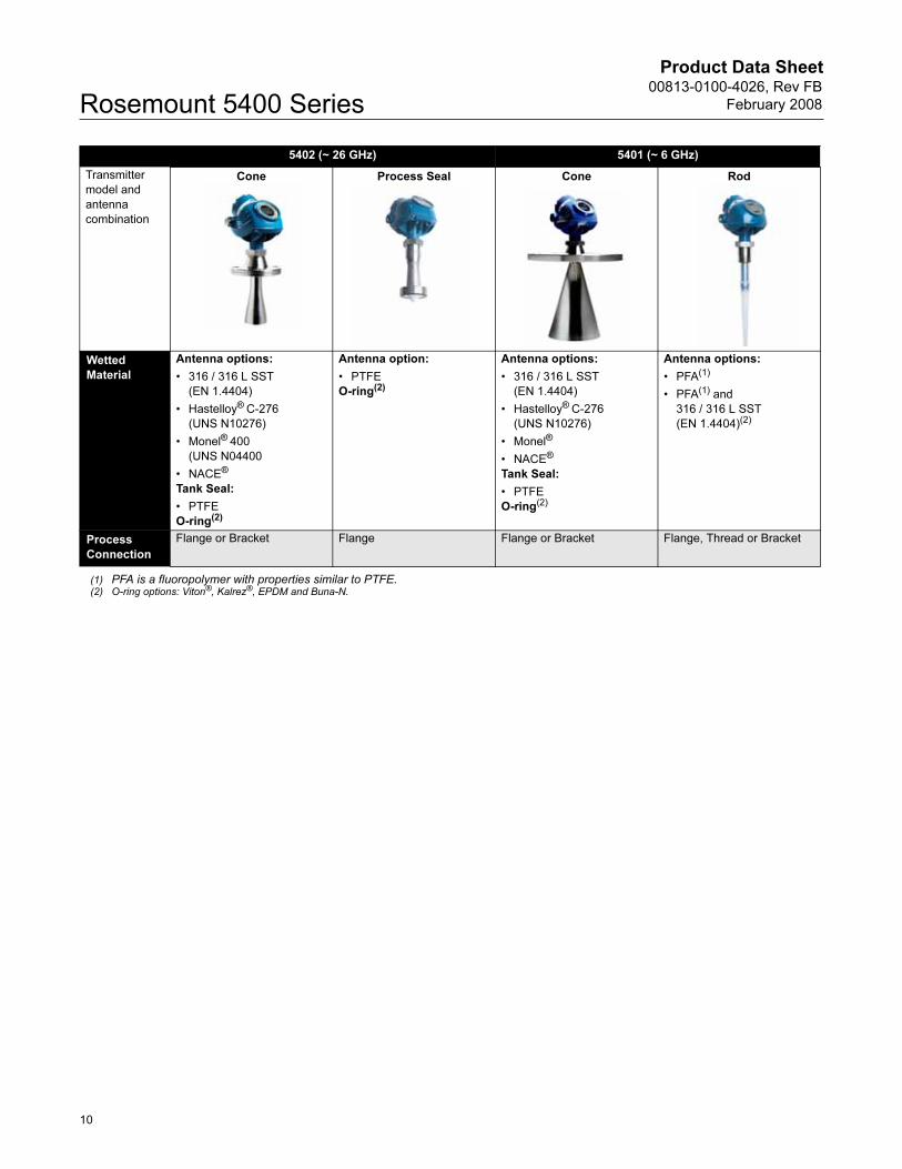
5402 (~ 26 GHz) 5401 (~ 6 GHz)
Transmitter
model and
antenna
combination
Cone Process Seal Cone Rod
Wetted
Material
Antenna options:
• 316 / 316 L SST
(EN 1.4404)
• Hastelloy® C-276
(UNS N10276)
• Monel® 400
(UNS N04400
• NACE®
Tank Seal:
• PTFE
O-ring(2)
Antenna option:
• PTFE
O-ring(2)
Antenna options:
• 316 / 316 L SST
(EN 1.4404)
• Hastelloy® C-276
(UNS N10276)
• Monel®
• NACE®
Tank Seal:
• PTFE
O-ring(2)
Antenna options:
• PFA(1)
• PFA(1) and
316 / 316 L SST
(EN 1.4404)(2)
Process
Connection
Flange or Bracket Flange Flange or Bracket Flange, Thread or Bracket
(1) PFA is a fluoropolymer with properties similar to PTFE.(2) O-ring options: Viton®, Kalrez®, EPDM and Buna-N.
10
Product Data Sheet00813-0100-4026, Rev FB
February 2008 Rosemount 5400 Series
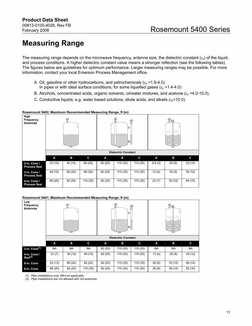
Measuring Range
The measuring range depends on the microwave frequency, antenna size, the dielectric constant (εr) of the liquid,
and process conditions. A higher dielectric constant value means a stronger reflection (see the following tables).
The figures below are guidelines for optimum performance. Larger measuring ranges may be possible. For more
information, contact your local Emerson Process Management office.
A. Oil, gasoline or other hydrocarbons, and petrochemicals (εr =1.9-4.0).In pipes or with ideal surface conditions, for some liquefied gases (εr =1.4-4.0)
B. Alcohols, concentrated acids, organic solvents, oil/water mixtures, and acetone (εr =4.0-10.0).
C. Conductive liquids, e.g. water based solutions, dilute acids, and alkalis (εr>10.0).
Rosemount 5402, Maximum Recommended Measuring Range, ft (m)
Rosemount 5401, Maximum Recommended Measuring Range, ft (m)
High FrequencyAntennas
Dielectric Constant
A B C A B C A B C
2-in. Cone / Process Seal
33 (10) 49 (15) 66 (20) 82 (25) 115 (35) 115 (35) 9.8 (3) 20 (6) 33 (10)
3-in. Cone / Process Seal
49 (15) 66 (20) 98 (30) 82 (25) 115 (35) 115 (35) 13 (4) 30 (9) 39 (12)
4-in. Cone / Process Seal
66 (20) 82 (25) 115 (35) 82 (25) 115 (35) 115 (35) 23 (7) 39 (12) 49 (15)
Low FrequencyAntennas
Dielectric Constant
A B C A B C A B C
3-in. Cone(1)
(1) Pipe installations only. NA=not applicable.
NA NA NA 82 (25) 115 (35) 115 (35) NA NA NA
4-in. Cone / Rod(2)
(2) Pipe installations are not allowed with rod antennas.
23 (7) 39 (12) 49 (15) 82 (25) 115 (35) 115 (35) 13 (4) 26 (8) 39 (12)
6-in. Cone 43 (13) 66 (20) 82 (25) 82 (25) 115 (35) 115 (35) 20 (6) 33 (10) 46 (14)
8-in. Cone 66 (20) 82 (25) 115 (35) 82 (25) 115 (35) 115 (35) 26 (8) 39 (12) 52 (16)
11
Product Data Sheet00813-0100-4026, Rev FB
February 2008Rosemount 5400 Series
Mechanical Mounting Recommendations
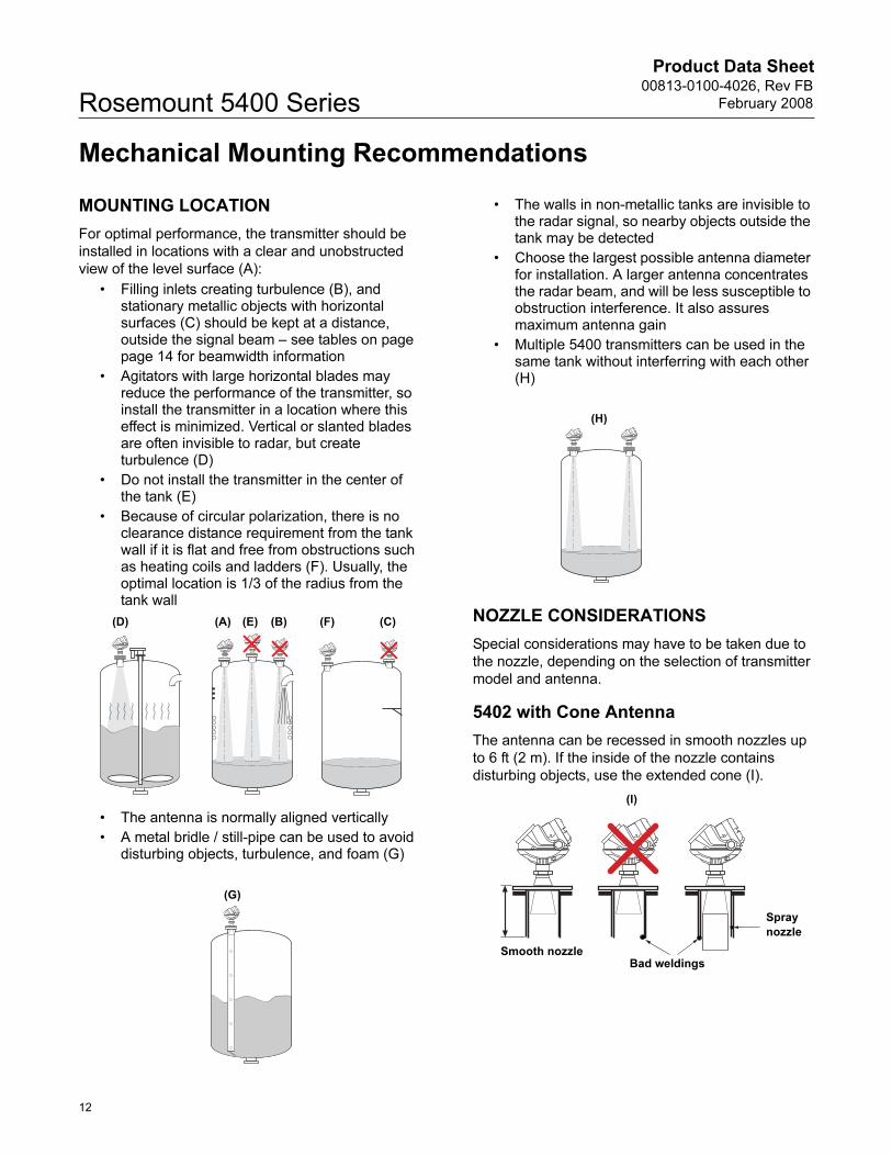
MOUNTING LOCATION
For optimal performance, the transmitter should be
installed in locations with a clear and unobstructed
view of the level surface (A):
• Filling inlets creating turbulence (B), and stationary metallic objects with horizontal surfaces (C) should be kept at a distance, outside the signal beam – see tables on page page 14 for beamwidth information
• Agitators with large horizontal blades may reduce the performance of the transmitter, so install the transmitter in a location where this effect is minimized. Vertical or slanted blades are often invisible to radar, but create turbulence (D)
• Do not install the transmitter in the center of the tank (E)
• Because of circular polarization, there is no clearance distance requirement from the tank wall if it is flat and free from obstructions such as heating coils and ladders (F). Usually, the optimal location is 1/3 of the radius from the tank wall
• The antenna is normally aligned vertically
• A metal bridle / still-pipe can be used to avoid disturbing objects, turbulence, and foam (G)
• The walls in non-metallic tanks are invisible to the radar signal, so nearby objects outside the tank may be detected
• Choose the largest possible antenna diameter for installation. A larger antenna concentrates the radar beam, and will be less susceptible to obstruction interference. It also assures maximum antenna gain
• Multiple 5400 transmitters can be used in the same tank without interferring with each other (H)
NOZZLE CONSIDERATIONS
Special considerations may have to be taken due to
the nozzle, depending on the selection of transmitter
model and antenna.
5402 with Cone Antenna
The antenna can be recessed in smooth nozzles up
to 6 ft (2 m). If the inside of the nozzle contains
disturbing objects, use the extended cone (I).
(A) (E) (B)(D) (C)(F)
(G)
(H)
Bad weldings
Spray
nozzle
Smooth nozzle
(I)
12
Product Data Sheet00813-0100-4026, Rev FB
February 2008 Rosemount 5400 Series
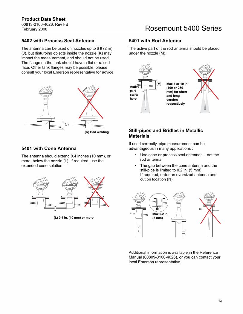
5402 with Process Seal Antenna
The antenna can be used on nozzles up to 6 ft (2 m),
(J), but disturbing objects inside the nozzle (K) may
impact the measurement, and should not be used.
The flange on the tank should have a flat or raised
face. Other tank flanges may be possible, please
consult your local Emerson representative for advice.
5401 with Cone Antenna
The antenna should extend 0.4 inches (10 mm), or
more, below the nozzle (L). If required, use the
extended cone solution.
5401 with Rod Antenna
The active part of the rod antenna should be placed
under the nozzle (M).
Still-pipes and Bridles in Metallic Materials
If used correctly, pipe measurement can be
advantageous in many applications :
• Use cone or process seal antennas – not the rod antenna.
• The gap between the cone antenna and the still-pipe is limited to 0.2 in. (5 mm). If required, order an oversized antenna and cut on location (N).
Additional information is available in the Reference
Manual (00809-0100-4026), or you can contact your
local Emerson representative.
(K) Bad welding
(J)
(L) 0.4 in. (10 mm) or more
(M) Max 4 or 10 in.
(100 or 250
mm) for short
and long
version
respectively.
Active
part
starts
here
(N)
Max 0.2 in.
(5 mm)
13
Product Data Sheet00813-0100-4026, Rev FB
February 2008Rosemount 5400 Series
Valves
The 5400 Series transmitter can be isolated from the
process by using a valve:
• Use a full-port ball valve
• The 5402 is required, and the Process Seal Antenna is the preferred choice, since it does not require a spool piece. The cone antenna can also be used
• Ensure there is no edge between the ball valve and the nozzle / pipe, the inside should be smooth
Valves can be combined with pipes.
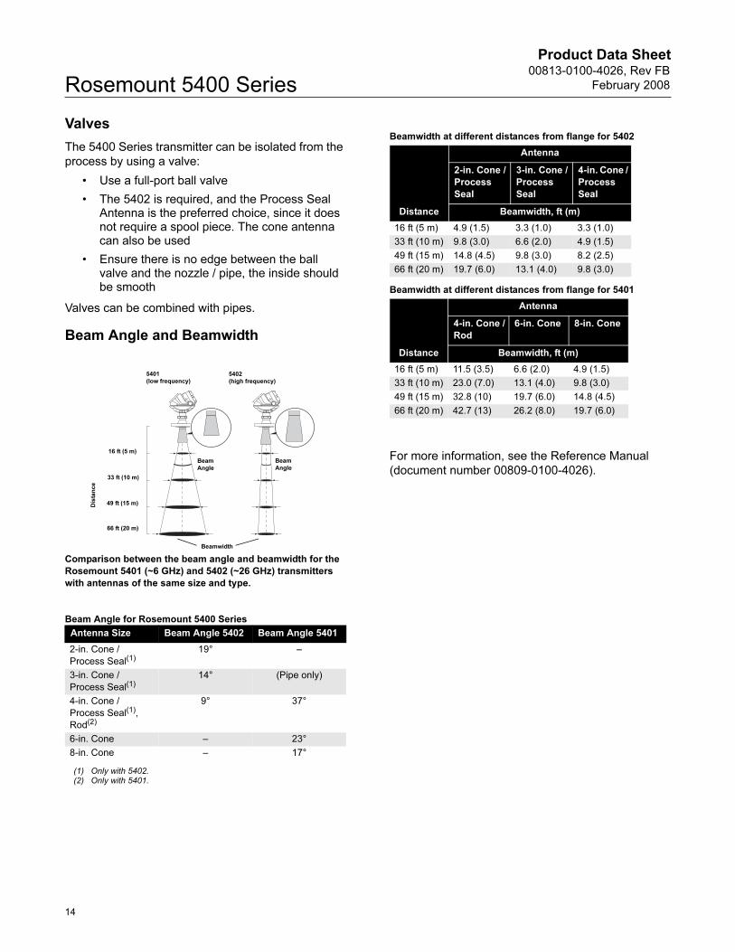
Beam Angle and Beamwidth
Comparison between the beam angle and beamwidth for the
Rosemount 5401 (~6 GHz) and 5402 (~26 GHz) transmitters
with antennas of the same size and type.
Beam Angle for Rosemount 5400 Series
Beamwidth at different distances from flange for 5402
Beamwidth at different distances from flange for 5401
For more information, see the Reference Manual
(document number 00809-0100-4026).
Antenna Size Beam Angle 5402 Beam Angle 5401
2-in. Cone /
Process Seal(1)
(1) Only with 5402.
19° –
3-in. Cone /
Process Seal(1)14° (Pipe only)
4-in. Cone /
Process Seal(1),
Rod(2)
(2) Only with 5401.
9° 37°
6-in. Cone – 23°
8-in. Cone – 17°
16 ft (5 m)
33 ft (10 m)
49 ft (15 m)
66 ft (20 m)
Dis
tan
ce
Beamwidth
5402
(high frequency)
5401
(low frequency)
Beam
Angle
Beam
Angle
Distance
Antenna
2-in. Cone /
Process
Seal
3-in. Cone /
Process
Seal
4-in. Cone /
Process
Seal
Beamwidth, ft (m)
16 ft (5 m) 4.9 (1.5) 3.3 (1.0) 3.3 (1.0)
33 ft (10 m) 9.8 (3.0) 6.6 (2.0) 4.9 (1.5)
49 ft (15 m) 14.8 (4.5) 9.8 (3.0) 8.2 (2.5)
66 ft (20 m) 19.7 (6.0) 13.1 (4.0) 9.8 (3.0)
Distance
Antenna
4-in. Cone /
Rod
6-in. Cone 8-in. Cone
Beamwidth, ft (m)
16 ft (5 m) 11.5 (3.5) 6.6 (2.0) 4.9 (1.5)
33 ft (10 m) 23.0 (7.0) 13.1 (4.0) 9.8 (3.0)
49 ft (15 m) 32.8 (10) 19.7 (6.0) 14.8 (4.5)
66 ft (20 m) 42.7 (13) 26.2 (8.0) 19.7 (6.0)
14
Product Data Sheet00813-0100-4026, Rev FB
February 2008 Rosemount 5400 Series
SpecificationsGeneral
Product Rosemount 5400 Series Radar Level Transmitter
Measurement Principle Pulsed, free propagating radar
5402: ~26 GHz
5401: ~6 GHz
Microwave Output Power < 1 mW
Beam Angle See table on page 12
Re-calibration Not required due to self-adjusting electronics.
Measuring Performance
Maximum Measuring Range 115 ft (35 m) from flange
Instrument Accuracy at reference
conditions(1)5402: ± 0.1 in. (± 3 mm)
5401: ± 0.4 in. (± 10 mm)
Repeatability ± 0.04 in. (± 1 mm) at 16.4 ft (5 m) distance
Resolution 0.04 in. (1 mm)
Near Zone Distance 1.3 ft (0.4 m) from lower end of the antenna
Near Zone Accuracy 5402: ± 0.6 in. (± 15 mm)
5401: ± 1.2 in. (± 30 mm)
Transition Zone(2) 6 in. (150 mm) from lower end of the antenna
Minimum Dielectric Constant εr = 1.4
Temperature Drift 0.05 %/10 K in temperature range -40°F to 176°F (-40°C to 80°C)
Update Interval 1 second
Max Level Rate 1.6 in./s (40 mm/s) as default, adjustable to 7.1 in./s (180 mm/s)
Display / Configuration / Communication
Integral Display 5-digit integral display. The process variables listed below can be presented. If more than one
variable is chosen, carousel toggling of data is used. The display also shows diagnostics and
error information.
Output Variables Level, Distance, Volume, Level Rate, Signal Strength, Internal Temperature, Analog Output
Current(3), and % of Range(3)
Output Units Level and Distance: ft, inch, m, cm or mm
Volume: ft3, inch3, US gals, Imp gals, barrels, yd3, m3, or liters
Level Rate: ft/s, m/s
Temperature: °F, °C
Configuration Tools HART®: Rosemount RadarMaster, Rosemount 275/375 Handheld Communicator, AMS Suite
or any other EDDL or enhanced-EDDL host
FOUNDATION™ fieldbus: Rosemount RadarMaster, 375 Handheld Communicator, DeltaV® or
any other DD (Device Description) compatible host system. Certificates of interoperability are
available from all major host system vendors.
FOUNDATION™ fieldbus Blocks Resource block, 3 Transducer blocks, 6 Analog Input (AI) blocks, Proportional
/Integral/Derivate (PID) block, Input Selector (ISEL) block, Signal Characterizer (SGCR)
block, Arithmetic (ARTH) block, and Output Splitter (OS) block
FOUNDATION™ fieldbus Class (Basic or Link
Master)
Link Master (LAS)
FOUNDATION™ fieldbus Block Execution Time AI-block: 30 ms. PID-block: 40 ms.
ARTH-, ISEL-, OSPL-block: 65 ms. CHAR-block: 75 ms
Conforming FOUNDATION™ fieldbus ITK 4.6
FOUNDATION™ fieldbus PlantWeb® Alert
Support
Yes
Electric
Terminal Supply Voltage See “Power Supply” on page 16
Internal Power Consumption < 50 mW in normal operation
Output HART® 4-20 mA current loop or FOUNDATION™ fieldbus
Signal on Alarm (configurable), HART® High=21.75 mA (standard setting)
Low=3.75 mA (option, model code C8)
Namur NE43: High=22.5 mA (option, model code C4)
15
Product Data Sheet00813-0100-4026, Rev FB
February 2008Rosemount 5400 Series
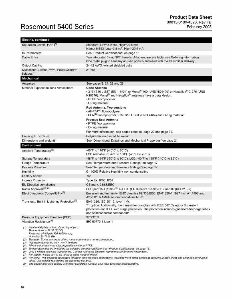
Electric, continued
Saturation Levels, HART® Standard: Low=3.9 mA, High=20.8 mA
Namur NE43: Low=3.8 mA, High=20.5 mA
IS Parameters See “Product Certifications” on page 18
Cable Entry Two integrated ½-in. NPT threads. Adapters are available, see Ordering Information.
One metal plug to seal any unused ports is enclosed with the transmitter delivery.
Output Cabling 24-12 AWG, twisted shielded pairs
Quiescent Current Draw ( FOUNDATION™
fieldbus)
21 mA
Mechanical
Antennas See pages 8, 21, 28 and 28
Material Exposed to Tank Atmosphere Cone Antenna
• 316 / 316 L SST (EN 1.4404) or Monel® 400 (UNS NO4400) or Hastelloy® C-276 (UNS
N10276). Monel® and Hastelloy® antennas have a plate design.
• PTFE fluoropolymer
• O-ring material.
Rod Antenna, Two versions
• All-PFA(4) fluoropolymer
• PFA(4) fluoropolymer, 316 / 316 L SST (EN 1.4404) and O-ring material.
Process Seal Antenna
• PTFE fluoropolymer
• O-ring material
For more information, see pages page 10, page 29 and page 32.
Housing / Enclosure Polyurethane-covered Aluminum
Dimensions and Weights See “Dimensional Drawings and Mechanical Properties” on page 21
Environment
Ambient Temperature(5) -40°F to 176°F (-40°C to 80°C).
LCD readable in: -4°F to 158°F (-20°C to 70°C).
Storage Temperature -58°F to 194°F (-50°C to 90°C). LCD: -40°F to 185°F (-40°C to 85°C)
Flange Temperature See “Temperature and Pressure Ratings” on page 17
Process Pressure See “Temperature and Pressure Ratings” on page 17
Humidity 0 - 100% Relative Humidity, non condensating
Factory Sealed Yes
Ingress Protection Type 4X, IP66, IP67
EU Directive compliance CE mark, 93/68/EEC
Radio Approvals(6)(7) FCC part 15C (1998)(8), R&TTE (EU directive 1999/5/EC), and IC (RSS210-5)
Electromagnetic Compatibility(9) Emission and Immunity: EMC directive 89/336/EEC. EN61326-1:1997 incl. A1:1998 and
A2:2001. NAMUR recommendations NE21.
Transient / Built-in Lightning Protection(9) EN61326, IEC 801-5, level 1 kV.
T1 option: Additionally, the transmitter complies with IEEE 587 Category B transient
protection and IEEE 472 surge protection. The protection includes gas-filled discharge tubes
and semiconductor components.
Pressure Equipment Directive (PED) 97/23/EC
Vibration Resistance(9) IEC 60770-1 level 1
(1) Ideal metal plate with no disturbing objects. Temperature: + 68 °F (20 °C). Pressure: 14-15 psi (960-1060 mbar). Humidity: 25-75 % RH.
(2) Transition Zones are areas where measurements are not recommended.(3) Not applicable for FOUNDATION™ fieldbus.(4) PFA is a fluoropolymer with properties similar to PTFE.(5) Temperature may be limited by the selected product certificate, see “Product Certifications” on page 18.(6) Only a limited selection is presented. Contact your local Emerson representative for more information.(7) For Japan: “Install device on tanks or pipes made of metal”.(8) For 5402: “This device is authorized for use in tank-mounted applications, including metal tanks as well as concrete, plastic, glass and other non-conductive
tanks.” No specific restrictions are stated for the 5401.(9) The device may also comply with other standards. Consult your local Emerson representative.
16
Product Data Sheet00813-0100-4026, Rev FB
February 2008 Rosemount 5400 Series
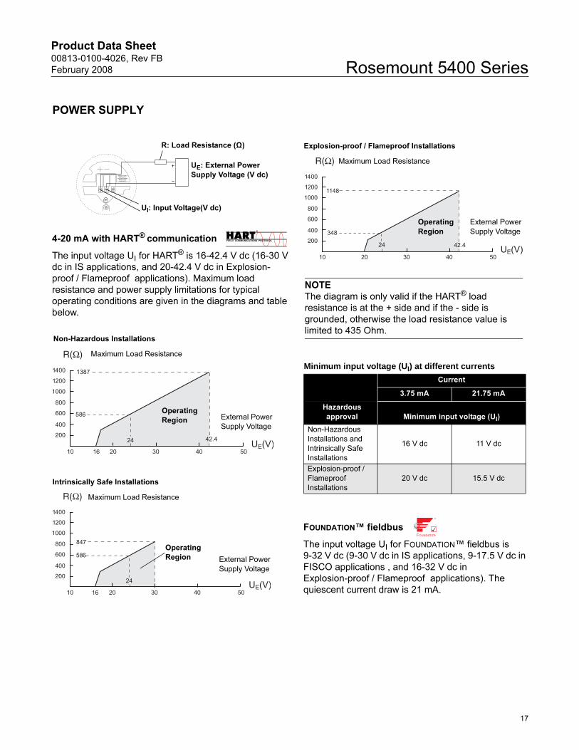
Non-Hazardous Installations
Maximum Load Resistance
NOTE
The diagram is only valid if the HART® load
resistance is at the + side and if the - side is
grounded, otherwise the load resistance value is
limited to 435 Ohm.
Operating
Region External Power
Supply Voltage
Explosion-proof / Flameproof Installations
Maximum Load Resistance
External Power
Supply Voltage
Operating
Region
Intrinsically Safe Installations
Operating
Region
Maximum Load Resistance
External Power
Supply Voltage
Minimum input voltage (UI) at different currents
Current
3.75 mA 21.75 mA
Hazardous
approval Minimum input voltage (UI)
Non-Hazardous
Installations and
Intrinsically Safe
Installations
16 V dc 11 V dc
Explosion-proof /
Flameproof
Installations
20 V dc 15.5 V dc
FOUNDATION™ fieldbus
The input voltage UI for FOUNDATION™ fieldbus is
9-32 V dc (9-30 V dc in IS applications, 9-17.5 V dc in
FISCO applications , and 16-32 V dc in
Explosion-proof / Flameproof applications). The
quiescent current draw is 21 mA.
4-20 mA with HART® communication
The input voltage UI for HART® is 16-42.4 V dc (16-30 V
dc in IS applications, and 20-42.4 V dc in Explosion-
proof / Flameproof applications). Maximum load
resistance and power supply limitations for typical
operating conditions are given in the diagrams and table
below.
POWER SUPPLY
R: Load Resistance (Ω)
UE: External Power
Supply Voltage (V dc)
UI: Input Voltage(V dc)
17
Product Data Sheet00813-0100-4026, Rev FB
February 2008Rosemount 5400 Series
18
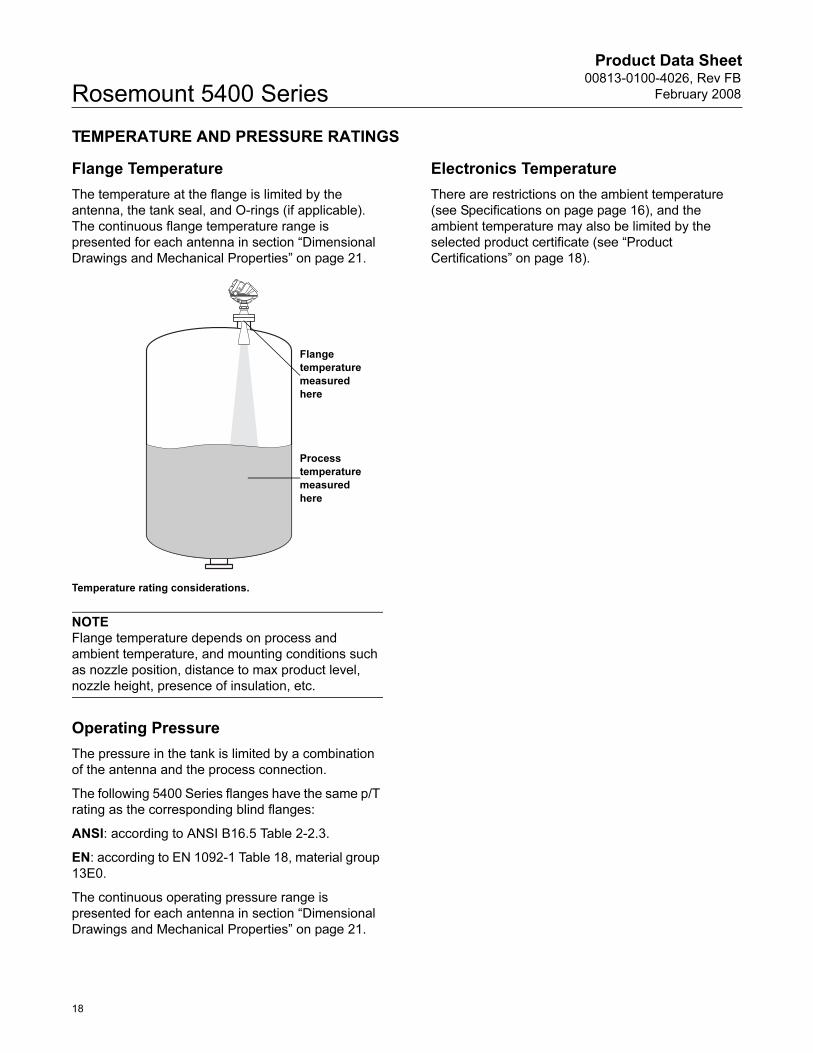
TEMPERATURE AND PRESSURE RATINGS
Flange Temperature
The temperature at the flange is limited by the
antenna, the tank seal, and O-rings (if applicable).
The continuous flange temperature range is
presented for each antenna in section “Dimensional
Drawings and Mechanical Properties” on page 21.
Temperature rating considerations.
NOTE
Flange temperature depends on process and
ambient temperature, and mounting conditions such
as nozzle position, distance to max product level,
nozzle height, presence of insulation, etc.
Operating Pressure
The pressure in the tank is limited by a combination
of the antenna and the process connection.
The following 5400 Series flanges have the same p/T
rating as the corresponding blind flanges:
ANSI: according to ANSI B16.5 Table 2-2.3.
EN: according to EN 1092-1 Table 18, material group
13E0.
The continuous operating pressure range is
presented for each antenna in section “Dimensional
Drawings and Mechanical Properties” on page 21.
Electronics Temperature
There are restrictions on the ambient temperature
(see Specifications on page page 16), and the
ambient temperature may also be limited by the
selected product certificate (see “Product
Certifications” on page 18).
Flange
temperature
measured
here
Process
temperature
measured
here
Product Data Sheet00813-0100-4026, Rev FB
February 2008 Rosemount 5400 Series
Product Certifications
SAFETY NOTE AND
SPECIAL CONDITIONS FOR SAFE USE (X-MARKING IN ATEX,
IECEX, AND NEPSI CERTIFICATES)
The intrinsically safe circuits do not withstand the 500 V ac test as
specified in EN 50020 clause 6.4.12.
Parts of the rod antenna and the process seal antenna are
non-conducting and the area of the non-conducting part exceeds
the maximum permissible areas for Group IIC according to
EN 50014, clause 7.3 (20 cm2) and Category II 1G according to
EN 50284, clause 4.4.3 (4 cm2) (20 cm2 for zone 1 and 4 cm2 for
zone 0 according to IEC 60079-0, clause 7.3). Therefore, when
the antenna is used in a potentionally explosive atmosphere,
appropriate measures must be taken to prevent electrostatic
discharge.
Impact and friction hazards need to be considered according to
EN 50284, clause 4.3.1 (IEC 60079-0, clause 8.1.2) when the
transmitter and part of antennas exposed to the exterior
atmosphere of the tank is made of light metal alloys, and used in
Category II 1 G (zone 0).
ATEX Approvals
Nemko 04ATEX1073X
E1(1) Flameproof:
II 1/2 GD T73°C(2).
EEx iad IIC T4 (-40°C<Ta<+70°C(3)).
Um=250 V
I1(1) Intrinsically Safe:
II 1 GD T73°C(2).
EEx ia IIC T4 (-50°C<Ta<+70°C(3)).
4-20 mA / HART® model: Ui=30 V dc, Ii=130 mA, Pi=1.0 W,
Ci=7.26 nF, Li=0 H.
FOUNDATION™ fieldbus model: Ui=30 V dc, Ii=300 mA,
Pi=1.5 W, Ci=0 nF, Li=0 H.
FISCO model: Ui=17.5 V dc, Ii=380 mA, Pi=5.32 W, Li=Ci=0.
Installation Drawing: 9150079-907.
National Supervision and Inspection Center for
Explosion Protection and Safety of Instrumentation
(NEPSI) Approvals
GYJ06242X, GYJ06458X
E3(1) Flameproof:
Ex iad IIC T4 (-40°C<Ta<+70°C(3)).
Um=250 V
I3(1) Intrinsically Safe:
Ex ia IIC T4 (-40°C<Ta<+70°C(3)).
4-20 mA / HART® model: Ui=30 V dc, Ii=130 mA, Pi=1.0 W,
Ci=7.26 nF, Li=0 H.
FOUNDATION™ fieldbus model: Ui=30 V dc, Ii=300 mA,
Pi=1.5 W, Ci=0 nF, Li=0 H.
FISCO model: Ui=17.5 V dc, Ii=380 mA, Pi=5.32 W, Li=Ci=0.
Installation Drawing: 9150079-907.
Technology Institution of Industrial Safety (TIIS)
Approval
E4(1) Flameproof:
Transmitter: Ex d [ia] IIC T4
Antenna: Ex ia IIC T4
Installation Drawing: 05400-00375A.
Factory Mutual (FM) Approvals
Project ID: 3020497
E5(1) Explosion-Proof for Class I, Div. 1,
Groups B, C and D;
Dust Ignition Proof for Class II/III, Div. 1, Groups E, F and G;
With Intrinsically Safe connections to
Class I, II, III, Div. 1, Groups B, C, D, E, F and G.
Temp. Code T4
Ambient temperature limits: -40°C to +70°C(3).
Seal not required.
I5(1) Intrinsically Safe for Class I, II, III, Div. 1, Groups A, B, C, D,
E, F and G,
Class I, Zone 0, AEx ia IIC T4 when installed per Control
Drawing: 9150079-905.
Non-Incendive Class I, Div. 2, Groups A, B, C and D;
Suitable for Class II, III, Div. 2, Groups F and G.
4-20 mA / HART® model: Ui=30 V dc, Ii=130 mA, Pi=1.0 W,
Ci=7.26 nF, Li=0 H.
FOUNDATION™ fieldbus model: Ui=30 V dc, Ii=300 mA,
Pi=1.3 W, Ci=0 nF, Li=0 H.
FISCO model: Ui=17.5 V dc, Ii=380 mA, Pi=5.32 W, Li=Ci=0.
Max operation:
4-20 mA / HART® model: 42.4 V, 25 mA,
FOUNDATION™ fieldbus model: 32 V, 25 mA.
Temp. Code T4
Ambient temperature limits: -40°C to +70°C(3).(1) Ordering Information code for Product Certificates, see
page page 31.
(2) +63°C with FOUNDATION™ fieldbus or FISCO option.
(3) +60°C with FOUNDATION™ fieldbus or FISCO option.
19
Product Data Sheet00813-0100-4026, Rev FB
February 2008Rosemount 5400 Series
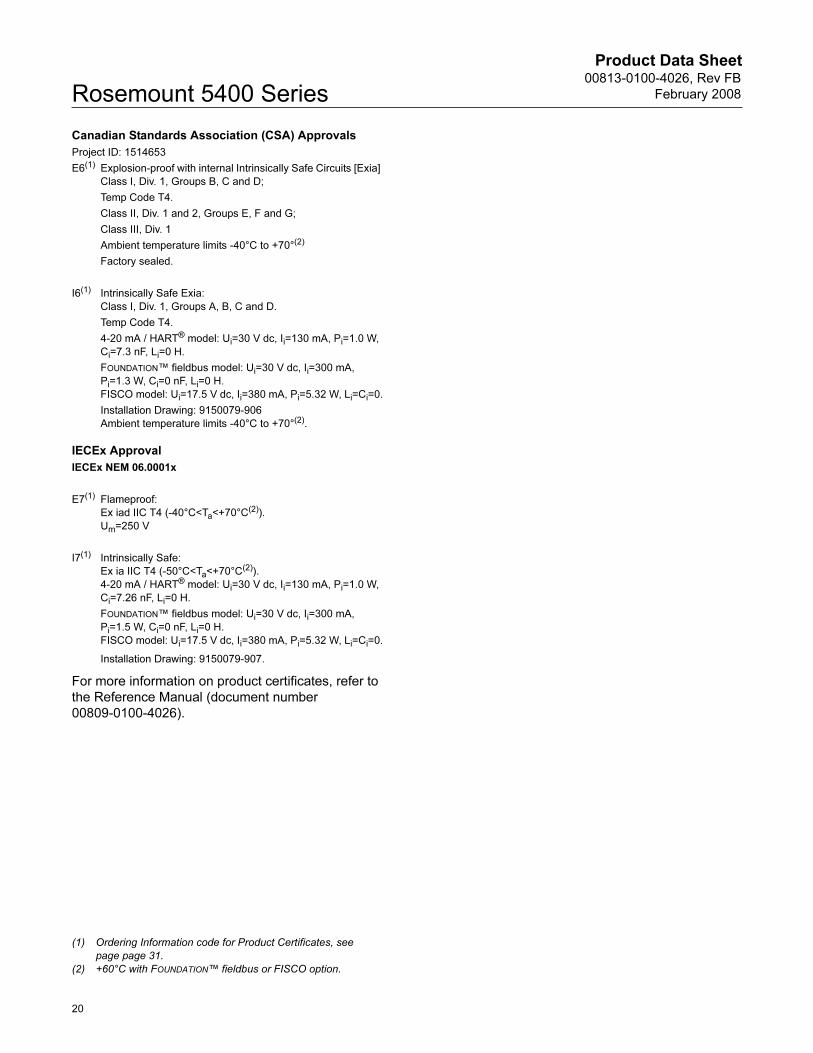
Canadian Standards Association (CSA) Approvals
Project ID: 1514653
E6(1) Explosion-proof with internal Intrinsically Safe Circuits [Exia]
Class I, Div. 1, Groups B, C and D;
Temp Code T4.
Class II, Div. 1 and 2, Groups E, F and G;
Class III, Div. 1
Ambient temperature limits -40°C to +70°(2)
Factory sealed.
I6(1) Intrinsically Safe Exia:
Class I, Div. 1, Groups A, B, C and D.
Temp Code T4.
4-20 mA / HART® model: Ui=30 V dc, Ii=130 mA, Pi=1.0 W,
Ci=7.3 nF, Li=0 H.
FOUNDATION™ fieldbus model: Ui=30 V dc, Ii=300 mA,
Pi=1.3 W, Ci=0 nF, Li=0 H.
FISCO model: Ui=17.5 V dc, Ii=380 mA, Pi=5.32 W, Li=Ci=0.
Installation Drawing: 9150079-906
Ambient temperature limits -40°C to +70°(2).
IECEx Approval
IECEx NEM 06.0001x
E7(1) Flameproof:
Ex iad IIC T4 (-40°C<Ta<+70°C(2)).
Um=250 V
I7(1) Intrinsically Safe:
Ex ia IIC T4 (-50°C<Ta<+70°C(2)).
4-20 mA / HART® model: Ui=30 V dc, Ii=130 mA, Pi=1.0 W,
Ci=7.26 nF, Li=0 H.
FOUNDATION™ fieldbus model: Ui=30 V dc, Ii=300 mA,
Pi=1.5 W, Ci=0 nF, Li=0 H.
FISCO model: Ui=17.5 V dc, Ii=380 mA, Pi=5.32 W, Li=Ci=0.
Installation Drawing: 9150079-907.
For more information on product certificates, refer to
the Reference Manual (document number
00809-0100-4026).
(1) Ordering Information code for Product Certificates, see
page page 31.
(2) +60°C with FOUNDATION™ fieldbus or FISCO option.
20
Product Data Sheet00813-0100-4026, Rev FB
February 2008 Rosemount 5400 Series
Dimensional Drawings and Mechanical Properties
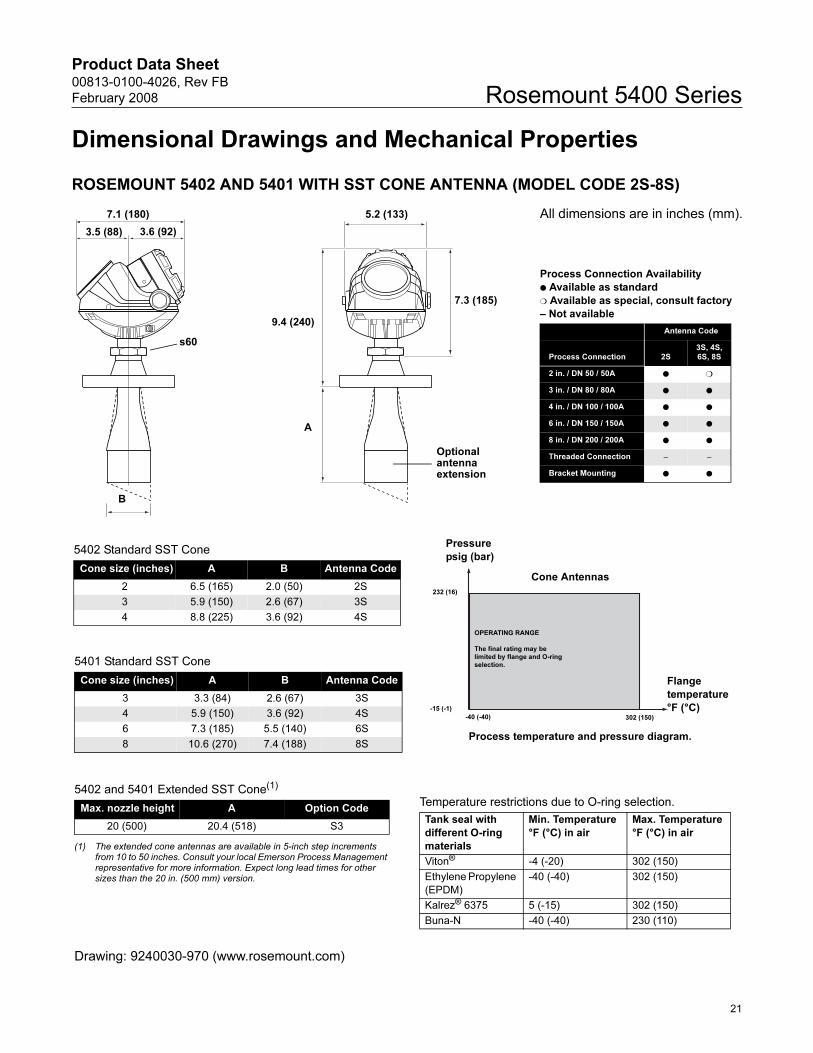
ROSEMOUNT 5402 AND 5401 WITH SST CONE ANTENNA (MODEL CODE 2S-8S)
B
A
9.4 (240)
7.3 (185)
3.5 (88) 3.6 (92)
s60
7.1 (180) 5.2 (133) All dimensions are in inches (mm).
5402 Standard SST Cone
Cone size (inches) A B Antenna Code
2 6.5 (165) 2.0 (50) 2S
3 5.9 (150) 2.6 (67) 3S
4 8.8 (225) 3.6 (92) 4S
5402 and 5401 Extended SST Cone(1)
(1) The extended cone antennas are available in 5-inch step increments from 10 to 50 inches. Consult your local Emerson Process Management representative for more information. Expect long lead times for other sizes than the 20 in. (500 mm) version.
Max. nozzle height A Option Code
20 (500) 20.4 (518) S3
Pressure
psig (bar)
Flange
temperature
°F (°C)-15 (-1)
232 (16)
-40 (-40) 302 (150)
OPERATING RANGE
The final rating may be
limited by flange and O-ring
selection.
Cone Antennas
Temperature restrictions due to O-ring selection.
Tank seal with
different O-ring
materials
Min. Temperature
°F (°C) in air
Max. Temperature
°F (°C) in air
Viton® -4 (-20) 302 (150)
Ethylene Propylene
(EPDM)
-40 (-40) 302 (150)
Kalrez® 6375 5 (-15) 302 (150)
Buna-N -40 (-40) 230 (110)
Process temperature and pressure diagram.
Drawing: 9240030-970 (www.rosemount.com)
5401 Standard SST Cone
Cone size (inches) A B Antenna Code
3 3.3 (84) 2.6 (67) 3S
4 5.9 (150) 3.6 (92) 4S
6 7.3 (185) 5.5 (140) 6S
8 10.6 (270) 7.4 (188) 8S
Optional antenna extension
Process Connection Availability
Available as standard
Available as special, consult factory
– Not available
Antenna Code
Process Connection 2S3S, 4S, 6S, 8S
2 in. / DN 50 / 50A
3 in. / DN 80 / 80A
4 in. / DN 100 / 100A
6 in. / DN 150 / 150A
8 in. / DN 200 / 200A
Threaded Connection– –
Bracket Mounting
21
Product Data Sheet00813-0100-4026, Rev FB
February 2008Rosemount 5400 Series
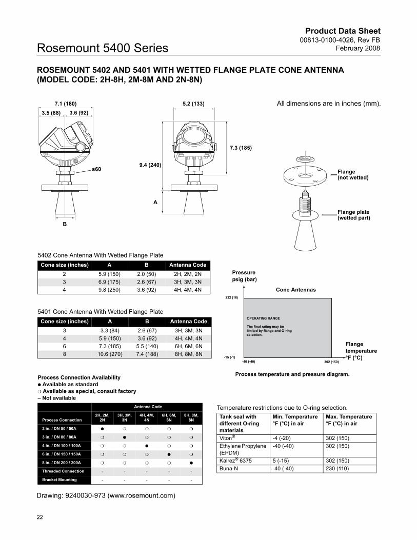
ROSEMOUNT 5402 AND 5401 WITH WETTED FLANGE PLATE CONE ANTENNA (MODEL CODE: 2H-8H, 2M-8M AND 2N-8N)
B
A
9.4 (240)
7.3 (185)
3.5 (88) 3.6 (92)
s60
7.1 (180) 5.2 (133)
Pressure
psig (bar)
Flange
temperature
°F (°C)-15 (-1)
232 (16)
-40 (-40) 302 (150)
OPERATING RANGE
The final rating may be
limited by flange and O-ring
selection.
Cone Antennas
Temperature restrictions due to O-ring selection.
Tank seal with
different O-ring
materials
Min. Temperature
°F (°C) in air
Max. Temperature
°F (°C) in air
Viton® -4 (-20) 302 (150)
Ethylene Propylene
(EPDM)
-40 (-40) 302 (150)
Kalrez® 6375 5 (-15) 302 (150)
Buna-N -40 (-40) 230 (110)
All dimensions are in inches (mm).
Flange(not wetted)
Flange plate (wetted part)
5402 Cone Antenna With Wetted Flange Plate
Cone size (inches) A B Antenna Code
2 5.9 (150) 2.0 (50) 2H, 2M, 2N
3 6.9 (175) 2.6 (67) 3H, 3M, 3N
4 9.8 (250) 3.6 (92) 4H, 4M, 4N
Process temperature and pressure diagram.Process Connection Availability
Available as standard
Available as special, consult factory
– Not available
Antenna Code
Process Connection2H, 2M,
2N3H, 3M,
3N4H, 4M,
4N6H, 6M,
6N8H, 8M,
8N
2 in. / DN 50 / 50A
3 in. / DN 80 / 80A
4 in. / DN 100 / 100A
6 in. / DN 150 / 150A
8 in. / DN 200 / 200A
Threaded Connection- - - - -
Bracket Mounting- - - - -
5401 Cone Antenna With Wetted Flange Plate
Cone size (inches) A B Antenna Code
3 3.3 (84) 2.6 (67) 3H, 3M, 3N
4 5.9 (150) 3.6 (92) 4H, 4M, 4N
6 7.3 (185) 5.5 (140) 6H, 6M, 6N
8 10.6 (270) 7.4 (188) 8H, 8M, 8N
Drawing: 9240030-973 (www.rosemount.com)
22
Product Data Sheet00813-0100-4026, Rev FB
February 2008 Rosemount 5400 Series
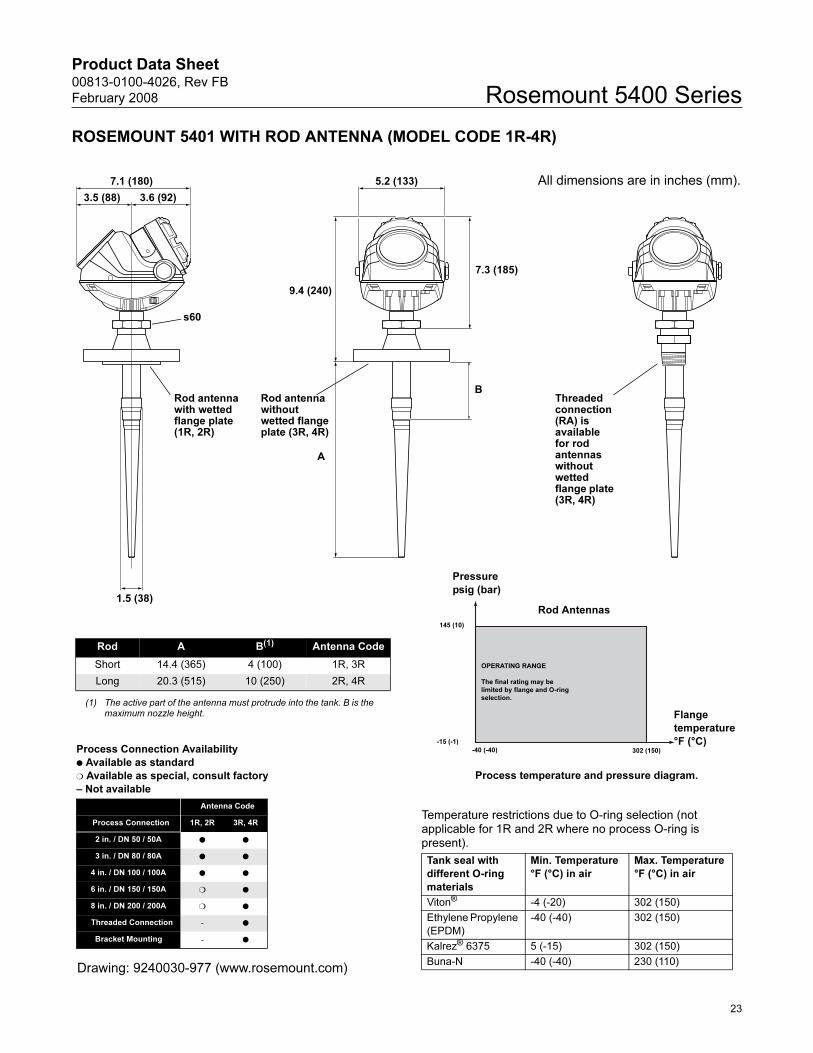
ROSEMOUNT 5401 WITH ROD ANTENNA (MODEL CODE 1R-4R)
A
1.5 (38)
7.1 (180) 5.2 (133)
7.3 (185)
s60
3.5 (88) 3.6 (92)
9.4 (240)
BRod antenna with wetted flange plate (1R, 2R)
Pressure
psig (bar)
Flange
temperature
°F (°C)-15 (-1)
145 (10)
-40 (-40) 302 (150)
OPERATING RANGE
The final rating may be
limited by flange and O-ring
selection.
Rod Antennas
Temperature restrictions due to O-ring selection (not applicable for 1R and 2R where no process O-ring is present).
Tank seal with
different O-ring
materials
Min. Temperature
°F (°C) in air
Max. Temperature
°F (°C) in air
Viton® -4 (-20) 302 (150)
Ethylene Propylene
(EPDM)
-40 (-40) 302 (150)
Kalrez® 6375 5 (-15) 302 (150)
Buna-N -40 (-40) 230 (110)
Rod A B(1)
(1) The active part of the antenna must protrude into the tank. B is the maximum nozzle height.
Antenna Code
Short 14.4 (365) 4 (100) 1R, 3R
Long 20.3 (515) 10 (250) 2R, 4R
All dimensions are in inches (mm).
Process temperature and pressure diagram.
Threaded connection (RA) is available for rod antennas without wetted flange plate (3R, 4R)
Rod antenna without wetted flange plate (3R, 4R)
Process Connection Availability
Available as standard
Available as special, consult factory
– Not available
Antenna Code
Process Connection 1R, 2R 3R, 4R
2 in. / DN 50 / 50A
3 in. / DN 80 / 80A
4 in. / DN 100 / 100A
6 in. / DN 150 / 150A
8 in. / DN 200 / 200A
Threaded Connection-
Bracket Mounting-
Drawing: 9240030-977 (www.rosemount.com)
23
Product Data Sheet00813-0100-4026, Rev FB
February 2008Rosemount 5400 Series
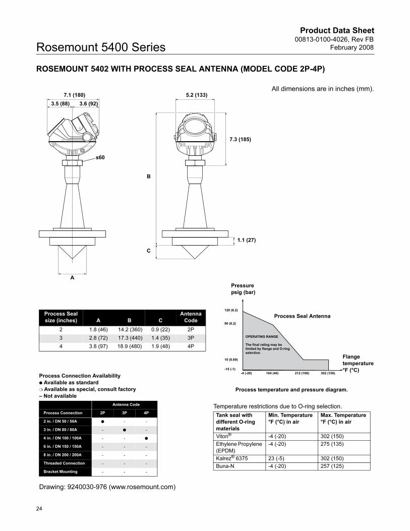
ROSEMOUNT 5402 WITH PROCESS SEAL ANTENNA (MODEL CODE 2P-4P)
s60
3.5 (88) 3.6 (92)
7.1 (180) 5.2 (133)
7.3 (185)
A
B
C
All dimensions are in inches (mm).
Temperature restrictions due to O-ring selection.
Tank seal with
different O-ring
materials
Min. Temperature
°F (°C) in air
Max. Temperature
°F (°C) in air
Viton® -4 (-20) 302 (150)
Ethylene Propylene
(EPDM)
-4 (-20) 275 (135)
Kalrez® 6375 23 (-5) 302 (150)
Buna-N -4 (-20) 257 (125)
Pressure
psig (bar)
Flange
temperature
°F (°C)-15 (-1)
120 (8.2)
-4 (-20)
90 (6.2)
10 (0.69)
104 (40) 212 (100) 302 (150)
OPERATING RANGE
The final rating may be
limited by flange and O-ring
selection.
Process Seal AntennaProcess Seal
size (inches) A B C
Antenna
Code
2 1.8 (46) 14.2 (360) 0.9 (22) 2P
3 2.8 (72) 17.3 (440) 1.4 (35) 3P
4 3.8 (97) 18.9 (480) 1.9 (48) 4P
Process temperature and pressure diagram.
Process Connection Availability
Available as standard
Available as special, consult factory
– Not available
Antenna Code
Process Connection 2P 3P 4P
2 in. / DN 50 / 50A - -
3 in. / DN 80 / 80A- -
4 in. / DN 100 / 100A- -
6 in. / DN 150 / 150A- - -
8 in. / DN 200 / 200A- - -
Threaded Connection- - -
Bracket Mounting- - -
Drawing: 9240030-976 (www.rosemount.com)
1.1 (27)
24
Product Data Sheet00813-0100-4026, Rev FB
February 2008 Rosemount 5400 Series
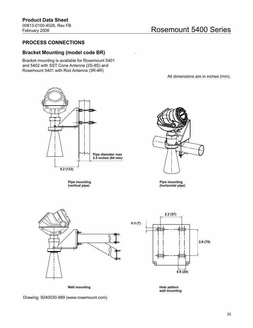
PROCESS CONNECTIONS
Bracket Mounting (model code BR)
Bracket mounting is available for Rosemount 5401
and 5402 with SST Cone Antenna (2S-8S) and
Rosemount 5401 with Rod Antenna (3R-4R)
.
2.8 (70)
2.2 (57)
0.3 (7)
0.8 (20)
All dimensions are in inches (mm).
Pipe mounting (horizontal pipe)
Pipe mounting (vertical pipe)
5.2 (133)
Pipe diameter max 2.5 inches (64 mm)
Wall mounting Hole pattern wall mounting
Drawing: 9240030-989 (www.rosemount.com)
25
Product Data Sheet00813-0100-4026, Rev FB
February 2008Rosemount 5400 Series
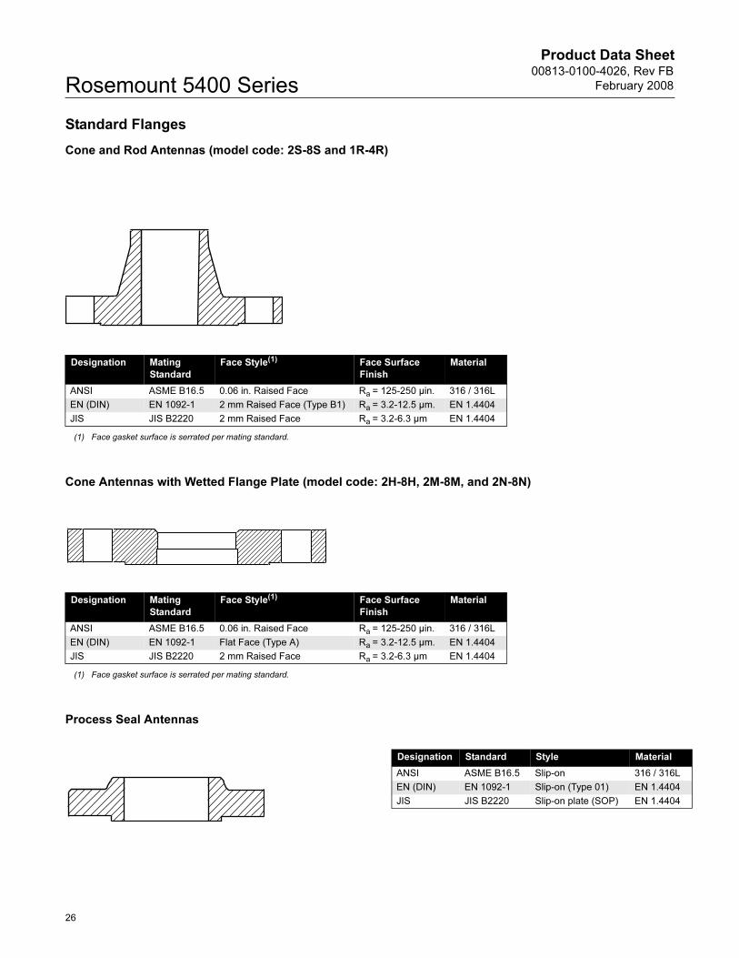
Standard Flanges
Cone and Rod Antennas (model code: 2S-8S and 1R-4R)
Cone Antennas with Wetted Flange Plate (model code: 2H-8H, 2M-8M, and 2N-8N)
Process Seal Antennas
Designation Mating
Standard
Face Style(1) Face Surface
Finish
Material
ANSI ASME B16.5 0.06 in. Raised Face Ra = 125-250 µin. 316 / 316L
EN (DIN) EN 1092-1 2 mm Raised Face (Type B1) Ra = 3.2-12.5 µm. EN 1.4404
JIS JIS B2220 2 mm Raised Face Ra = 3.2-6.3 µm EN 1.4404
(1) Face gasket surface is serrated per mating standard.
Designation Mating
Standard
Face Style(1) Face Surface
Finish
Material
ANSI ASME B16.5 0.06 in. Raised Face Ra = 125-250 µin. 316 / 316L
EN (DIN) EN 1092-1 Flat Face (Type A) Ra = 3.2-12.5 µm. EN 1.4404
JIS JIS B2220 2 mm Raised Face Ra = 3.2-6.3 µm EN 1.4404
(1) Face gasket surface is serrated per mating standard.
Designation Standard Style Material
ANSI ASME B16.5 Slip-on 316 / 316L
EN (DIN) EN 1092-1 Slip-on (Type 01) EN 1.4404
JIS JIS B2220 Slip-on plate (SOP) EN 1.4404
26
Product Data Sheet00813-0100-4026, Rev FB
February 2008 Rosemount 5400 Series
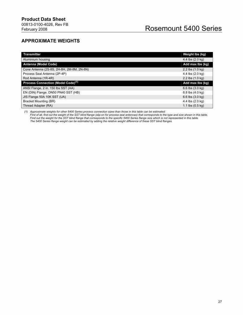
APPROXIMATE WEIGHTS
Transmitter Weight lbs (kg)
Aluminium housing 4.4 lbs (2.0 kg)
Antenna (Model Code) Add max lbs (kg)
Cone Antenna (2S-8S, 2H-8H, 2M-8M, 2N-8N) 2.2 lbs (1.0 kg)
Process Seal Antenna (2P-4P) 4.4 lbs (2.0 kg)
Rod Antenna (1R-4R) 2.2 lbs (1.0 kg)
Process Connection (Model Code)(1) Add max lbs (kg)
ANSI Flange, 2 in. 150 lbs SST (AA) 6.6 lbs (3.0 kg)
EN (DIN) Flange, DN50 PN40 SST (HB) 8.8 lbs (4.0 kg)
JIS Flange 50A 10K SST (UA) 6.6 lbs (3.0 kg)
Bracket Mounting (BR) 4.4 lbs (2.0 kg)
Thread Adapter (RA) 1.1 lbs (0.5 kg)
(1) Approximate weights for other 5400 Series process connection sizes than those in this table can be estimated: First of all, find out the weight of the SST blind flange (slip-on for process seal antennas) that corresponds to the type and size shown in this table. Find out the weight for the SST blind flange that corresponds to the specific 5400 Series flange size which is not represented in this table. The 5400 Series flange weight can be estimated by adding the relative weight difference of these SST blind flanges.
27
Product Data Sheet00813-0100-4026, Rev FB
February 2008Rosemount 5400 Series
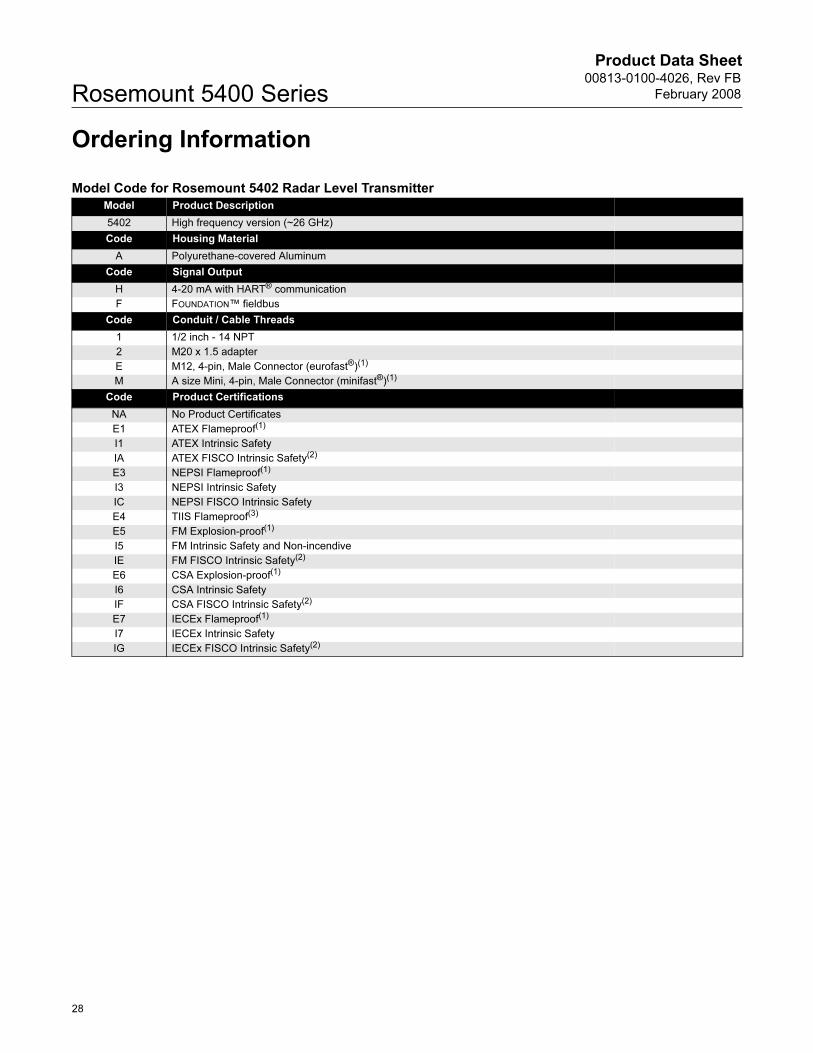
Ordering Information
Model Code for Rosemount 5402 Radar Level Transmitter
Model Product Description
5402 High frequency version (~26 GHz)
Code Housing Material
A Polyurethane-covered Aluminum
Code Signal Output
H 4-20 mA with HART® communication
F FOUNDATION™ fieldbus
Code Conduit / Cable Threads
1 1/2 inch - 14 NPT
2 M20 x 1.5 adapter
E M12, 4-pin, Male Connector (eurofast®)(1)
M A size Mini, 4-pin, Male Connector (minifast®)(1)
Code Product Certifications
NA No Product Certificates
E1 ATEX Flameproof(1)
I1 ATEX Intrinsic Safety
IA ATEX FISCO Intrinsic Safety(2)
E3 NEPSI Flameproof(1)
I3 NEPSI Intrinsic Safety
IC NEPSI FISCO Intrinsic Safety
E4 TIIS Flameproof(3)
E5 FM Explosion-proof(1)
I5 FM Intrinsic Safety and Non-incendive
IE FM FISCO Intrinsic Safety(2)
E6 CSA Explosion-proof(1)
I6 CSA Intrinsic Safety
IF CSA FISCO Intrinsic Safety(2)
E7 IECEx Flameproof(1)
I7 IECEx Intrinsic Safety
IG IECEx FISCO Intrinsic Safety(2)
28
Product Data Sheet00813-0100-4026, Rev FB
February 2008 Rosemount 5400 Series
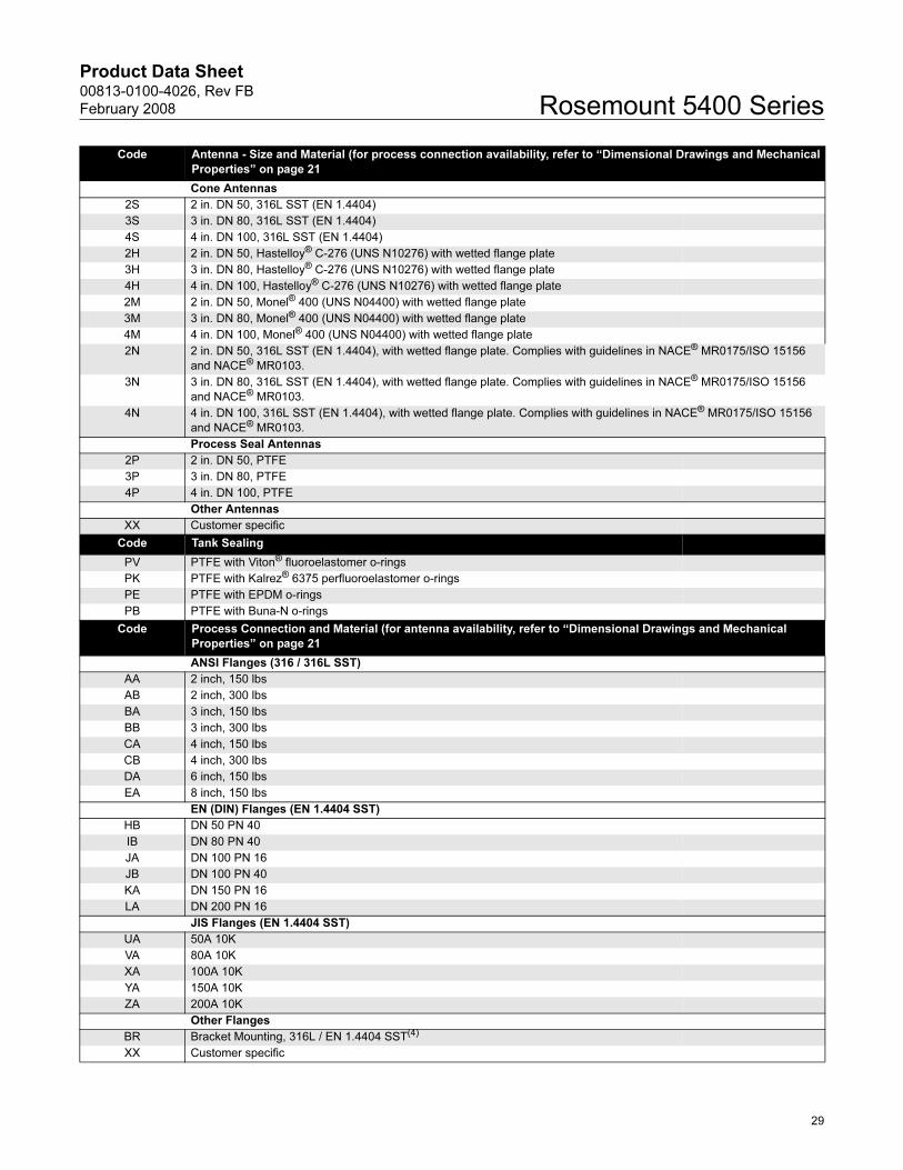
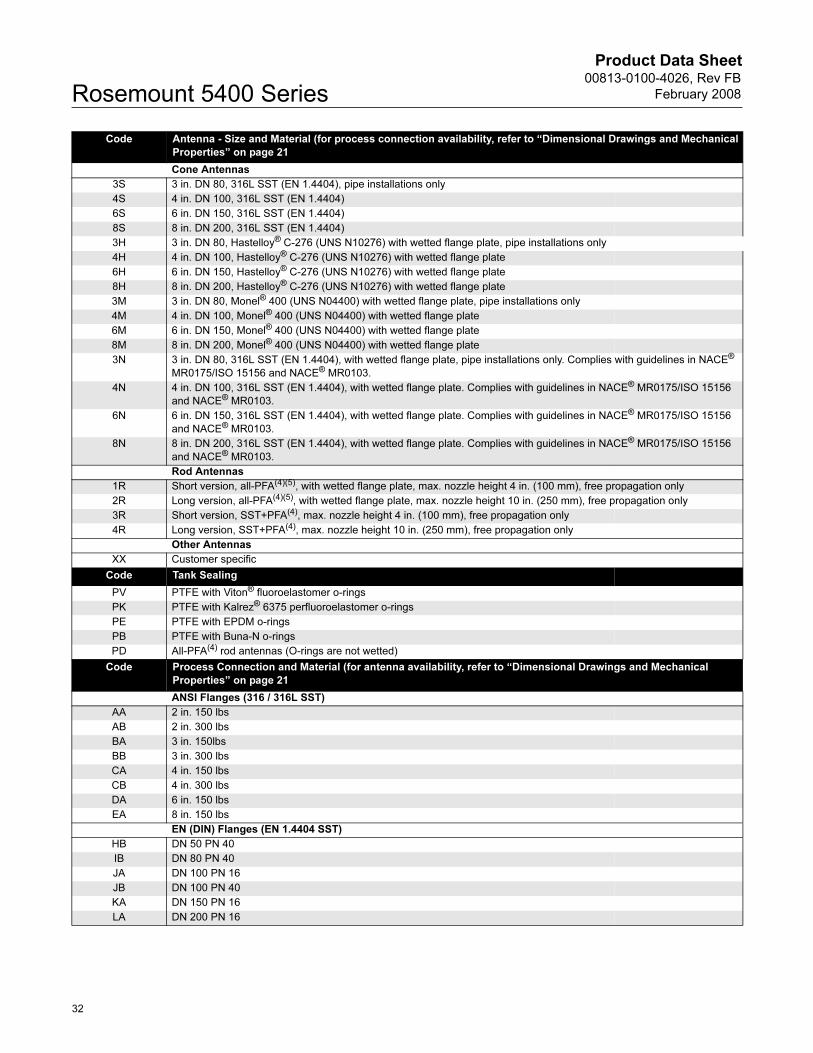
Code Antenna - Size and Material (for process connection availability, refer to “Dimensional Drawings and Mechanical
Properties” on page 21
Cone Antennas
2S 2 in. DN 50, 316L SST (EN 1.4404)
3S 3 in. DN 80, 316L SST (EN 1.4404)
4S 4 in. DN 100, 316L SST (EN 1.4404)
2H 2 in. DN 50, Hastelloy® C-276 (UNS N10276) with wetted flange plate
3H 3 in. DN 80, Hastelloy® C-276 (UNS N10276) with wetted flange plate
4H 4 in. DN 100, Hastelloy® C-276 (UNS N10276) with wetted flange plate
2M 2 in. DN 50, Monel® 400 (UNS N04400) with wetted flange plate
3M 3 in. DN 80, Monel® 400 (UNS N04400) with wetted flange plate
4M 4 in. DN 100, Monel® 400 (UNS N04400) with wetted flange plate
2N 2 in. DN 50, 316L SST (EN 1.4404), with wetted flange plate. Complies with guidelines in NACE® MR0175/ISO 15156
and NACE® MR0103.
3N 3 in. DN 80, 316L SST (EN 1.4404), with wetted flange plate. Complies with guidelines in NACE® MR0175/ISO 15156
and NACE® MR0103.
4N 4 in. DN 100, 316L SST (EN 1.4404), with wetted flange plate. Complies with guidelines in NACE® MR0175/ISO 15156
and NACE® MR0103.
Process Seal Antennas
2P 2 in. DN 50, PTFE
3P 3 in. DN 80, PTFE
4P 4 in. DN 100, PTFE
Other Antennas
XX Customer specific
Code Tank Sealing
PV PTFE with Viton® fluoroelastomer o-rings
PK PTFE with Kalrez® 6375 perfluoroelastomer o-rings
PE PTFE with EPDM o-rings
PB PTFE with Buna-N o-rings
Code Process Connection and Material (for antenna availability, refer to “Dimensional Drawings and Mechanical
Properties” on page 21
ANSI Flanges (316 / 316L SST)
AA 2 inch, 150 lbs
AB 2 inch, 300 lbs
BA 3 inch, 150 lbs
BB 3 inch, 300 lbs
CA 4 inch, 150 lbs
CB 4 inch, 300 lbs
DA 6 inch, 150 lbs
EA 8 inch, 150 lbs
EN (DIN) Flanges (EN 1.4404 SST)
HB DN 50 PN 40
IB DN 80 PN 40
JA DN 100 PN 16
JB DN 100 PN 40
KA DN 150 PN 16
LA DN 200 PN 16
JIS Flanges (EN 1.4404 SST)
UA 50A 10K
VA 80A 10K
XA 100A 10K
YA 150A 10K
ZA 200A 10K
Other Flanges
BR Bracket Mounting, 316L / EN 1.4404 SST(4)
XX Customer specific
29
Product Data Sheet00813-0100-4026, Rev FB
February 2008Rosemount 5400 Series
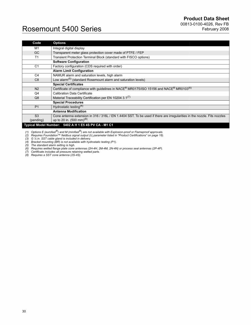
Code Options
M1 Integral digital display
GC Transparent meter glass protection cover made of PTFE / FEP
T1 Transient Protection Terminal Block (standard with FISCO options)
Software Configuration
C1 Factory configuration (CDS required with order)
Alarm Limit Configuration
C4 NAMUR alarm and saturation levels, high alarm
C8 Low alarm(5) (standard Rosemount alarm and saturation levels)
Special Certificates
N2 Certificate of compliance with guidelines in NACE® MR0175/ISO 15156 and NACE® MR0103(6)
Q4 Calibration Data Certificate
Q8 Material Traceability Certification per EN 10204 3.1(7)
Special Procedures
P1 Hydrostatic testing(4)
Antenna Modification
S3
(pending)
Cone antenna extension in 316 / 316L / EN 1.4404 SST. To be used if there are irregularities in the nozzle. Fits nozzles
up to 20 in. (500 mm)(8).
Typical Model Number: 5402 A H 1 E5 4S PV CA - M1 C1
(1) Options E (eurofast®) and M (minifast®) are not available with Explosion-proof or Flameproof approvals.(2) Requires Foundation™ fieldbus signal output (Ui parameter listed in “Product Certifications” on page 18).(3) G ½ in. SST cable gland is included in delivery.(4) Bracket mounting (BR) is not available with hydrostatic testing (P1).(5) The standard alarm setting is high.(6) Requires wetted flange plate cone antennas (2H-4H, 2M-4M, 2N-4N) or process seal antennas (2P-4P).(7) Certificate includes all pressure retaining wetted parts.(8) Requires a SST cone antenna (2S-4S).
30
Product Data Sheet00813-0100-4026, Rev FB
February 2008 Rosemount 5400 Series
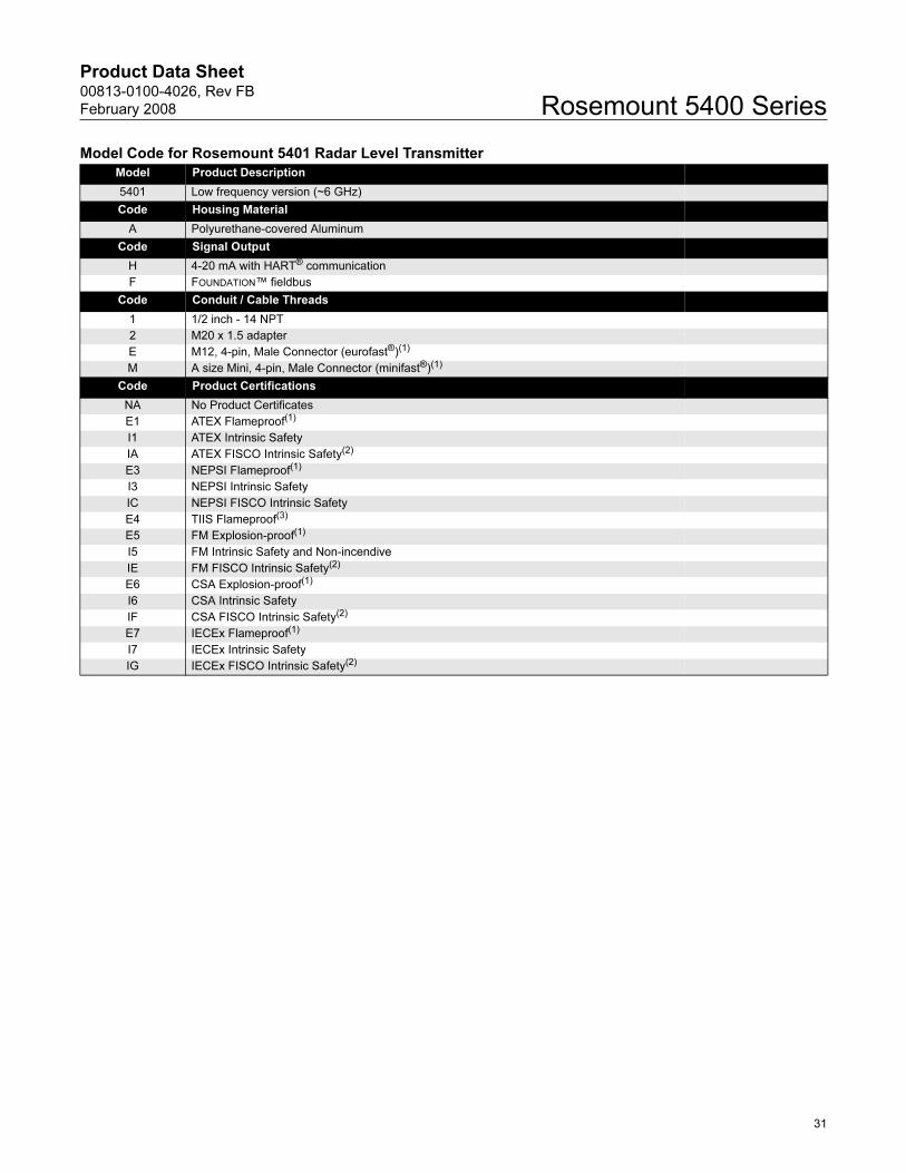
Model Code for Rosemount 5401 Radar Level Transmitter
Model Product Description
5401 Low frequency version (~6 GHz)
Code Housing Material
A Polyurethane-covered Aluminum
Code Signal Output
H 4-20 mA with HART® communication
F FOUNDATION™ fieldbus
Code Conduit / Cable Threads
1 1/2 inch - 14 NPT
2 M20 x 1.5 adapter
E M12, 4-pin, Male Connector (eurofast®)(1)
M A size Mini, 4-pin, Male Connector (minifast®)(1)
Code Product Certifications
NA No Product Certificates
E1 ATEX Flameproof(1)
I1 ATEX Intrinsic Safety
IA ATEX FISCO Intrinsic Safety(2)
E3 NEPSI Flameproof(1)
I3 NEPSI Intrinsic Safety
IC NEPSI FISCO Intrinsic Safety
E4 TIIS Flameproof(3)
E5 FM Explosion-proof(1)
I5 FM Intrinsic Safety and Non-incendive
IE FM FISCO Intrinsic Safety(2)
E6 CSA Explosion-proof(1)
I6 CSA Intrinsic Safety
IF CSA FISCO Intrinsic Safety(2)
E7 IECEx Flameproof(1)
I7 IECEx Intrinsic Safety
IG IECEx FISCO Intrinsic Safety(2)
31
Product Data Sheet00813-0100-4026, Rev FB
February 2008Rosemount 5400 Series
Code Antenna - Size and Material (for process connection availability, refer to “Dimensional Drawings and Mechanical
Properties” on page 21
Cone Antennas
3S 3 in. DN 80, 316L SST (EN 1.4404), pipe installations only
4S 4 in. DN 100, 316L SST (EN 1.4404)
6S 6 in. DN 150, 316L SST (EN 1.4404)
8S 8 in. DN 200, 316L SST (EN 1.4404)
3H 3 in. DN 80, Hastelloy® C-276 (UNS N10276) with wetted flange plate, pipe installations only
4H 4 in. DN 100, Hastelloy® C-276 (UNS N10276) with wetted flange plate
6H 6 in. DN 150, Hastelloy® C-276 (UNS N10276) with wetted flange plate
8H 8 in. DN 200, Hastelloy® C-276 (UNS N10276) with wetted flange plate
3M 3 in. DN 80, Monel® 400 (UNS N04400) with wetted flange plate, pipe installations only
4M 4 in. DN 100, Monel® 400 (UNS N04400) with wetted flange plate
6M 6 in. DN 150, Monel® 400 (UNS N04400) with wetted flange plate
8M 8 in. DN 200, Monel® 400 (UNS N04400) with wetted flange plate
3N 3 in. DN 80, 316L SST (EN 1.4404), with wetted flange plate, pipe installations only. Complies with guidelines in NACE®
MR0175/ISO 15156 and NACE® MR0103.
4N 4 in. DN 100, 316L SST (EN 1.4404), with wetted flange plate. Complies with guidelines in NACE® MR0175/ISO 15156
and NACE® MR0103.
6N 6 in. DN 150, 316L SST (EN 1.4404), with wetted flange plate. Complies with guidelines in NACE® MR0175/ISO 15156
and NACE® MR0103.
8N 8 in. DN 200, 316L SST (EN 1.4404), with wetted flange plate. Complies with guidelines in NACE® MR0175/ISO 15156
and NACE® MR0103.
Rod Antennas
1R Short version, all-PFA(4)(5), with wetted flange plate, max. nozzle height 4 in. (100 mm), free propagation only
2R Long version, all-PFA(4)(5), with wetted flange plate, max. nozzle height 10 in. (250 mm), free propagation only
3R Short version, SST+PFA(4), max. nozzle height 4 in. (100 mm), free propagation only
4R Long version, SST+PFA(4), max. nozzle height 10 in. (250 mm), free propagation only
Other Antennas
XX Customer specific
Code Tank Sealing
PV PTFE with Viton® fluoroelastomer o-rings
PK PTFE with Kalrez® 6375 perfluoroelastomer o-rings
PE PTFE with EPDM o-rings
PB PTFE with Buna-N o-rings
PD All-PFA(4) rod antennas (O-rings are not wetted)
Code Process Connection and Material (for antenna availability, refer to “Dimensional Drawings and Mechanical
Properties” on page 21
ANSI Flanges (316 / 316L SST)
AA 2 in. 150 lbs
AB 2 in. 300 lbs
BA 3 in. 150lbs
BB 3 in. 300 lbs
CA 4 in. 150 lbs
CB 4 in. 300 lbs
DA 6 in. 150 lbs
EA 8 in. 150 lbs
EN (DIN) Flanges (EN 1.4404 SST)
HB DN 50 PN 40
IB DN 80 PN 40
JA DN 100 PN 16
JB DN 100 PN 40
KA DN 150 PN 16
LA DN 200 PN 16
32
Product Data Sheet00813-0100-4026, Rev FB
February 2008 Rosemount 5400 Series
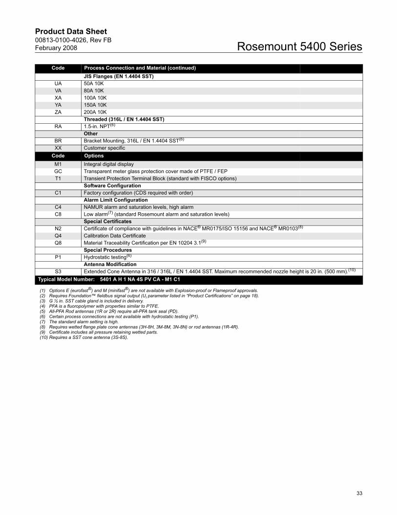
Code Process Connection and Material (continued)
JIS Flanges (EN 1.4404 SST)
UA 50A 10K
VA 80A 10K
XA 100A 10K
YA 150A 10K
ZA 200A 10K
Threaded (316L / EN 1.4404 SST)
RA 1.5-in. NPT(6)
Other
BR Bracket Mounting, 316L / EN 1.4404 SST(6)
XX Customer specific
Code Options
M1 Integral digital display
GC Transparent meter glass protection cover made of PTFE / FEP
T1 Transient Protection Terminal Block (standard with FISCO options)
Software Configuration
C1 Factory configuration (CDS required with order)
Alarm Limit Configuration
C4 NAMUR alarm and saturation levels, high alarm
C8 Low alarm(7) (standard Rosemount alarm and saturation levels)
Special Certificates
N2 Certificate of compliance with guidelines in NACE® MR0175/ISO 15156 and NACE® MR0103(8)
Q4 Calibration Data Certificate
Q8 Material Traceability Certification per EN 10204 3.1(9)
Special Procedures
P1 Hydrostatic testing(6)
Antenna Modification
S3 Extended Cone Antenna in 316 / 316L / EN 1.4404 SST. Maximum recommended nozzle height is 20 in. (500 mm).(10)
Typical Model Number: 5401 A H 1 NA 4S PV CA - M1 C1
(1) Options E (eurofast®) and M (minifast®) are not available with Explosion-proof or Flameproof approvals.(2) Requires Foundation™ fieldbus signal output (Ui parameter listed in “Product Certifications” on page 18).(3) G ½ in. SST cable gland is included in delivery.(4) PFA is a fluoropolymer with properties similar to PTFE.(5) All-PFA Rod antennas (1R or 2R) require all-PFA tank seal (PD).(6) Certain process connections are not available with hydrostatic testing (P1).(7) The standard alarm setting is high.(8) Requires wetted flange plate cone antennas (3H-8H, 3M-8M, 3N-8N) or rod antennas (1R-4R).(9) Certificate includes all pressure retaining wetted parts.(10) Requires a SST cone antenna (3S-8S).
33
Product Data Sheet00813-0100-4026, Rev FB
February 2008Rosemount 5400 Series
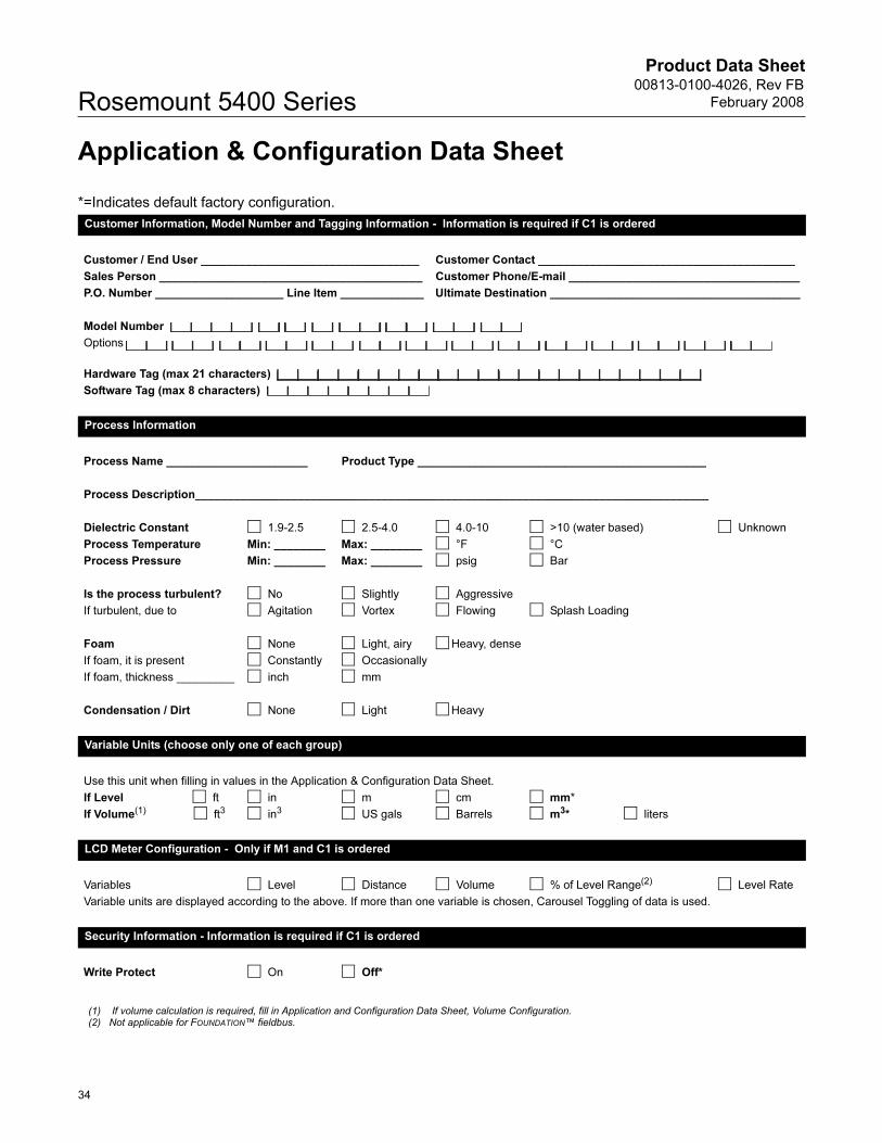
Application & Configuration Data Sheet
*=Indicates default factory configuration.
Customer Information, Model Number and Tagging Information - Information is required if C1 is ordered
Customer / End User __________________________________ Customer Contact ________________________________________
Sales Person _________________________________________ Customer Phone/E-mail ____________________________________
P.O. Number ____________________ Line Item _____________ Ultimate Destination _______________________________________
Model Number
Options
Hardware Tag (max 21 characters)
Software Tag (max 8 characters)
Process Information
Process Name ______________________ Product Type _____________________________________________
Process Description________________________________________________________________________________
Dielectric Constant 1.9-2.5 2.5-4.0 4.0-10 >10 (water based) Unknown
Process Temperature Min: ________ Max: ________ °F °C
Process Pressure Min: ________ Max: ________ psig Bar
Is the process turbulent? No Slightly Aggressive
If turbulent, due to Agitation Vortex Flowing Splash Loading
Foam None Light, airy Heavy, dense
If foam, it is present Constantly Occasionally
If foam, thickness _________ inch mm
Condensation / Dirt None Light Heavy
Variable Units (choose only one of each group)
Use this unit when filling in values in the Application & Configuration Data Sheet.
If Level ft in m cm mm*
If Volume(1) ft3 in3 US gals Barrels m3* liters
LCD Meter Configuration - Only if M1 and C1 is ordered
Variables Level Distance Volume % of Level Range(2) Level Rate
Variable units are displayed according to the above. If more than one variable is chosen, Carousel Toggling of data is used.
Security Information - Information is required if C1 is ordered
Write Protect On Off*
(1) If volume calculation is required, fill in Application and Configuration Data Sheet, Volume Configuration.(2) Not applicable for FOUNDATION™ fieldbus.
34
Product Data Sheet00813-0100-4026, Rev FB
February 2008 Rosemount 5400 Series
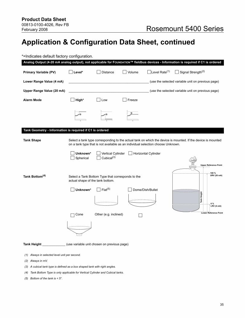
Application & Configuration Data Sheet, continued
*=Indicates default factory configuration.
Analog Output (4-20 mA analog output), not applicable for FOUNDATION™ fieldbus devices - Information is required if C1 is ordered
Primary Variable (PV) Level* Distance Volume Level Rate(1) Signal Strength(2)
Lower Range Value (4 mA) _____________________________________________ (use the selected variable unit on previous page)
Upper Range Value (20 mA) _____________________________________________ (use the selected variable unit on previous page)
Alarm Mode High* Low Freeze
Tank Geometry - Information is required if C1 is ordered
Tank Shape Select a tank type corresponding to the actual tank on which the device is mounted. If the device is mounted
on a tank type that is not available as an individual selection choose Unknown.
Unknown* Vertical Cylinder Horizontal Cylinder
Spherical Cubical(3)
Tank Bottom(4) Select a Tank Bottom Type that corresponds to the
actual shape of the tank bottom.
Unknown* Flat(5) Dome/Dish/Bullet
Cone Other (e.g. inclined)
Tank Height _____________ (use variable unit chosen on previous page)
(1) Always in selected level unit per second.
(2) Always in mV.
(3) A cubical tank type is defined as a box shaped tank with right angles.
(4) Tank Bottom Type is only applicable for Vertical Cylinder and Cubical tanks.
(5) Bottom of the tank is < 5°.
Upper Reference Point
Lower Reference Point
Ta
nk
He
igh
t0 %
LRV (4 mA)
100 %
URV (20 mA)
35
Product Data Sheet00813-0100-4026, Rev FB
February 2008Rosemount 5400 Series
Application & Configuration Data Sheet, continued
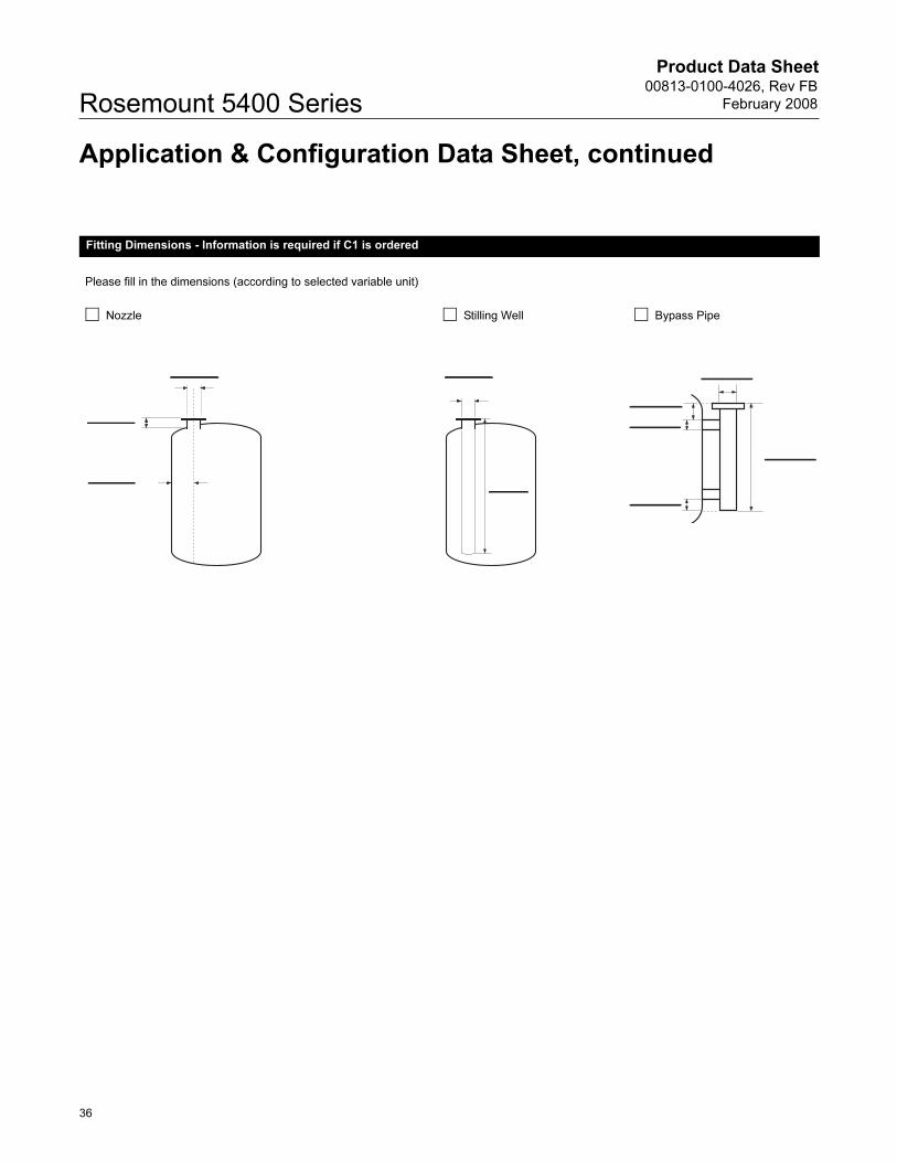
Fitting Dimensions - Information is required if C1 is ordered
Please fill in the dimensions (according to selected variable unit)
Nozzle Stilling Well Bypass Pipe
36
Product Data Sheet00813-0100-4026, Rev FB
February 2008 Rosemount 5400 Series
Application & Configuration Data Sheet, continued
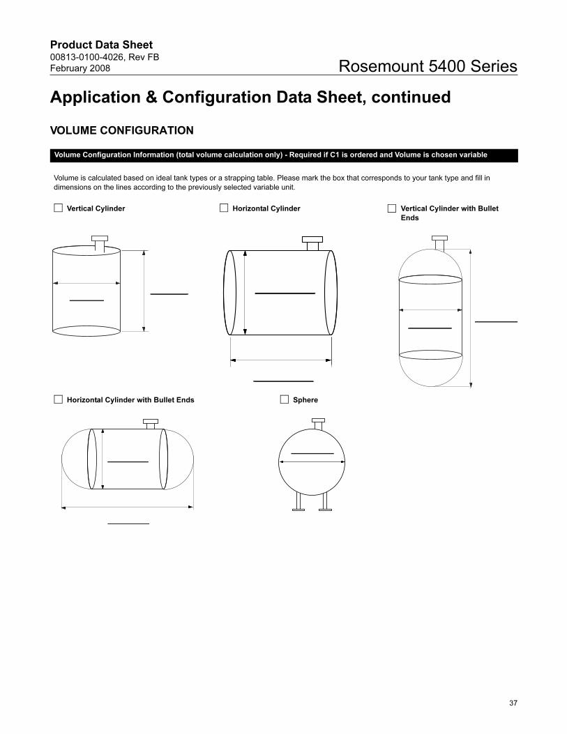
VOLUME CONFIGURATION
Volume Configuration Information (total volume calculation only) - Required if C1 is ordered and Volume is chosen variable
Volume is calculated based on ideal tank types or a strapping table. Please mark the box that corresponds to your tank type and fill in
dimensions on the lines according to the previously selected variable unit.
Vertical Cylinder Horizontal Cylinder Vertical Cylinder with Bullet
Ends
Horizontal Cylinder with Bullet Ends Sphere
37

Product Data Sheet00813-0100-4026, Rev FB
February 2008Rosemount 5400 Series
38

Product Data Sheet00813-0100-4026, Rev FB
February 2008
39
Rosemount 5400 Series
Product Data Sheet00813-0100-4026, Rev FB
February 2008 Rosemount 5400 Series
Rosemount and the Rosemount logotype are registered trademarks of Rosemount Inc.PlantWeb is a registered trademark of one of the Emerson Process Management group of companies.HART is a registered trademark of the HART Communication FoundationViton, and Kalrez are registered trademarks of Du Pont Performance Elastomers.FOUNDATION is a trademark of the Fieldbus Foundation.DeltaV is a trademark of Emerson Process Management group of companies.Hastelloy is a registered trademark of Haynes International.
Rosemount Level Solutions
Emerson provides a complete range of Rosemount products for level measurement applications.
Pressure – Level or Interface Measurement
Emerson has a complete line of Rosemount pressure transmitters and remote seals for measuring level or interfaces in liquid applications. Optimize performance with direct mount, Tuned Seal systems:
• Rosemount 3051S_L, 3051L, and 1151LT Liquid Level Transmitters
• Rosemount 1199 Remote Diaphragm Seals with direct mount or capillary connections
Vibrating Fork Switches – Point Level Detection
The Rosemount 2100 Series is developed for reliable point level detection of liquids and consists of:
• Rosemount 2110 Compact Vibrating Fork Liquid Level Switch
• Rosemount 2120 Full-featured Vibrating Fork Liquid Level Switch
Guided Wave Radar – Level and Interface Measurement
Multivariable, loop-powered Guided Wave Radar transmitters with a wide range of probe styles to fit different liquids and solids applications. The product line consists of:
• Rosemount 3300 Series – Versatile and easy-to-use transmitter with proven reliability
• Rosemount 5300 Series – Accurate, high performance transmitter with FOUNDATION™ fieldbus support
Non-contacting Radar – Level Measurement
The Rosemount non-contacting radar family consists of:
• Rosemount 5400 Series Transmitters – Loop-poweredtransmitter with a wide range of antennas, for liquid level measurement in most applications and process conditions
• Rosemount 5600 Series Transmitters – Transmitters with ultra-high sensitivity for measurement of level in liquids and solids, even for the most challenging applications
Non-contacting Ultrasonic – Level Measurement
The Rosemount 3100 Series ultrasonic level transmitters provide continuous non-contacting level measurement of liquids. The range consisits of:
• Rosemount 3101 for simple continuous level measurement
• Rosemount 3102 for continuous measurement with two integral relays for local control functionality
• Rosemount 3105 Intrinsically safe certified version for hazardous areas
Emerson Process Management, Rosemount Inc.
© 2008 Rosemount Inc. All rights reserved.
The AmericasEmerson Process Management8200 Market BoulevardChanhassen, MN 55317 USAT (U.S.) 1-800-999-9307T (International) (952) 906-8888F (952) 949-7001
Europe, Middle East & AfricaEmerson Process ManagementShared Services Ltd.Heath PlaceBognor RegisWest Sussex PO22 9SHEnglandTel 44 1243 845500Fax 44 1243 867554
Asia PacificEmerson Process ManagementSingapore Pte Ltd.1 Pandan CrescentSingapore 128461Tel 65 6777 8211Fax 65 6777 [email protected]
www.rosemount.com
¢00813-0100-4026;¤
Monel is a registered trademark of International Nickel Co.Eurofast and Minifast are registered trademarks of Turck Inc.All other marks are the property of their respective owners.
Standard Terms and Conditions of Sale can be found at www.rosemount.com\terms_of_sale