Embed Size (px)
Citation preview
Two-stroke Low Speed Diesel Enginesfor Independent Power Producers and Captive Power Plants


Contents
Abstract .......................................................................................................5
Preface ........................................................................................................5
The diesel engine and its competitors ...........................................................6
Diesel engines in stationary applications .......................................................6
Load Flexibility .............................................................................................7
Fuel Linkage ................................................................................................8
Fuel flexibility ................................................................................................8
Emissions .................................................................................................. 12
Two-stroke Engine Driven Plants ................................................................. 12
The Cheju Plants .................................................................................. 12
The Chennai Plant ................................................................................ 14
Conclusion ................................................................................................. 15

4
5Two-stroke Low Speed Diesel Engines for Independent Power Producers and Captive Power Plants 5
Two-stroke Low Speed Diesel Engines for Independent Power Producers and Captive Power Plants
Abstract
In recent years, the stationary diesel
engine market for large diesel units has
seen an increasing demand for reliable
and fuel efficient power plants in the
range of 30-250 MW, based on cost ef-
fective refinery residuals.
The demand is met by the modern me-
dium speed diesel GenSets and, for
the larger units, by the two-stroke low
speed crosshead uniflow scavenged
diesel engines, the latter capable of
burning almost any fuel available on the
market, whether liquid or gaseous.
This paper will deal with the service ex-
perience gained from two-stroke low
speed diesel engines and their fuel ca-
pability as well as describe various in-
stallation examples.
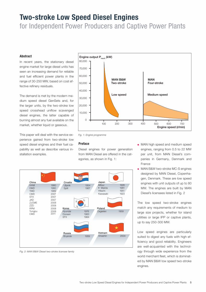
Preface
Diesel engines for power generation
from MAN Diesel are offered in the cat-
egories, as shown in Fig. 1:
� MAN high speed and medium speed
engines, ranging from 0.5 to 22 MW
per unit, from MAN Diesel’s com-
panies in Germany, Denmark and
France
� MAN B&W two-stroke MC-S engines
designed by MAN Diesel, Copenha-
gen, Denmark. These are low speed
engines with unit outputs of up to 80
MW. The engines are built by MAN
Diesel’s licensees listed in Fig. 2
The low speed two-stroke engines
match any requirements of medium to
large size projects, whether for island
utilities or large IPP or captive plants,
up to say 250-300 MW.
Low speed engines are particularly
suited to digest any fuels with high ef-
ficiency and good reliability. Engineers
are well-acquainted with the technol-
ogy through wide experience from the
world merchant fleet, which is dominat-
ed by MAN B&W low speed two-stroke
engines.
30,000
20,000
40,000
600
10,000
60,000
50,000
Engine output Pmech (kW)
0
700Engine speed (r/min)
500200 300 400
Medium speed
70,000
100
Four-stroke
80,000
Two-stroke
Low speed
MAN B&W MAN
Fig. 1: Engine programme
PolandCegielski 1959
RussiaBryansk 1959
JapanMitsui 1926• Makita 1981Hitachi 1951Kawasaki 1923
CroatiaUljanik 1954Split 1967
VietnamVinashin 2004
KoreaHyundai 1976Doosan 1983STX 1984
ChinaHHM 1980DMD 1980YMD 1989CMD 2007STX 2007JAD 2007ZJCME 2008ZZD 2008RPM 2008
CMD2008Yungpu2011
Fig. 2: MAN B&W Diesel twostroke licensee family
6 Two-stroke Low Speed Diesel Engines for Independent Power Producers and Captive Power Plants
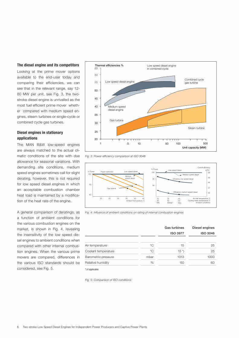
The diesel engine and its competitors
Looking at the prime mover options
available to the end-user today and
comparing their efficiencies, we can
see that in the relevant range, say 12-
80 MW per unit, see Fig. 3, the two-
stroke diesel engine is unrivalled as the
most fuel efficient prime mover wheth-
er compared with medium speed en-
gines, steam turbines or single-cycle or
combined cycle gas turbines.
Diesel engines in stationary applications
The MAN B&W low-speed engines
are always matched to the actual cli-
matic conditions of the site with due
allowance for seasonal variations. With
demanding site conditions, medium
speed engines sometimes call for slight
derating, however, this is not required
for low speed diesel engines in which
an acceptable combustion chamber
heat load is maintained by a modifica-
tion of the heat rate of the engine.
A general comparison of deratings, as
a function of ambient conditions for
the various combustion engines on the
market, is shown in Fig. 4, revealing
the insensitivity of the low speed die-
sel engines to ambient conditions when
compared with other internal combus-
tion engines. When the various prime
movers are compared, differences in
the various ISO standards should be
considered, see Fig. 5.
Medium speeddiesel engine
Unit capacity (MW)
Gas turbine
Combined cyclegas turbine
Steam turbine
100
20
500501 105 100
20
500501 105
35
30
40
25
50
45
35
30
40
25
50
45
60
55
65Thermal efficiencies %
Low speed diesel engine
Low speed diesel enginein combined cycle
Fig. 3: Power efficiency comparison at ISO 3046
25
48
80
Air inlet temperature CCooling water temperature C
Ambient conditions
o
o
46
100
90
Mediumspeed diesel
3542Design
Overall efficiency
Gas turbine
Low speed diesel
30 35 4520 40
% Power Power restriction
Efficiency, low speed diesel
% Power
2535Min.
4552Max.
50
49
Ambient temperature Co
47
80
100
90
Low speed diesel
Efficiency, medium speed diesel
Medium speed diesel
η (%)
Fig. 4: Influence of ambient conditions on rating of internal combustion engines
Gas turbines
ISO 3977
Diesel engines
ISO 3046
Air temperature °C 15 25
Coolant temperature °C 15 *) 25
Barometric pressure mbar 1013 1000
Relative humidity % 60 60
*) if applicable
Fig. 5: Comparison of ISO conditions
7Two-stroke Low Speed Diesel Engines for Independent Power Producers and Captive Power Plants
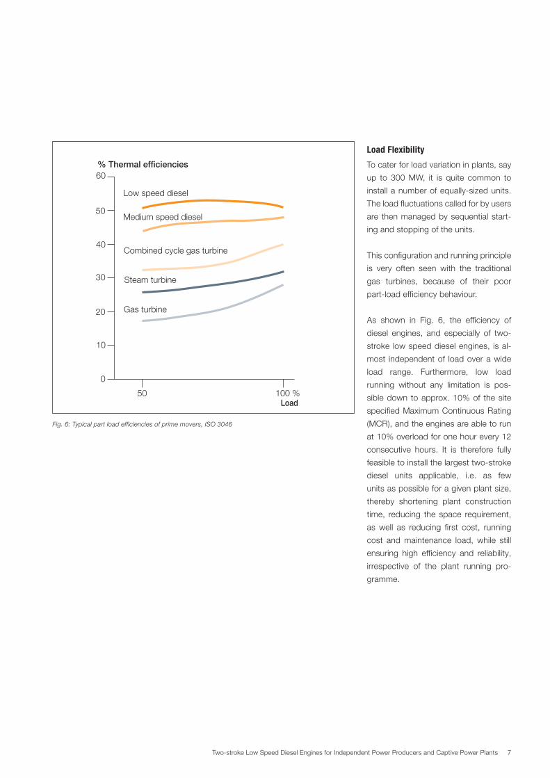
Load Flexibility
To cater for load variation in plants, say
up to 300 MW, it is quite common to
install a number of equally-sized units.
The load fluctuations called for by users
are then managed by sequential start-
ing and stopping of the units.
This configuration and running principle
is very often seen with the traditional
gas turbines, because of their poor
part-load efficiency behaviour.
As shown in Fig. 6, the efficiency of
diesel engines, and especially of two-
stroke low speed diesel engines, is al-
most independent of load over a wide
load range. Furthermore, low load
running without any limitation is pos-
sible down to approx. 10% of the site
specified Maximum Continuous Rating
(MCR), and the engines are able to run
at 10% overload for one hour every 12
consecutive hours. It is therefore fully
feasible to install the largest two-stroke
diesel units applicable, i.e. as few
units as possible for a given plant size,
thereby shortening plant construction
time, reducing the space requirement,
as well as reducing first cost, running
cost and maintenance load, while still
ensuring high efficiency and reliability,
irrespective of the plant running pro-
gramme.
% Thermal efficiencies
Low speed diesel
Medium speed diesel
Combined cycle gas turbine
Steam turbine
Gas turbine
30
20
40
10
60
50
0
100 %Load
50
Fig. 6: Typical part load efficiencies of prime movers, ISO 3046
8 Two-stroke Low Speed Diesel Engines for Independent Power Producers and Captive Power Plants
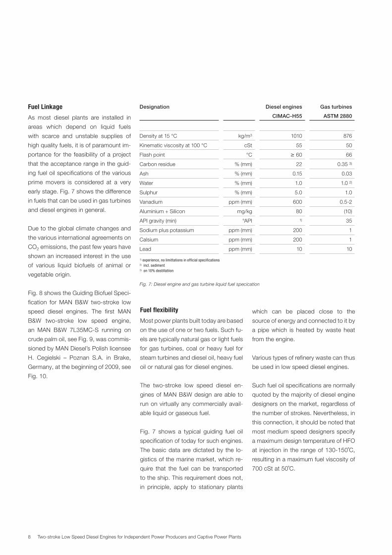
Fuel Linkage
As most diesel plants are installed in
areas which depend on liquid fuels
with scarce and unstable supplies of
high quality fuels, it is of paramount im-
portance for the feasibility of a project
that the acceptance range in the guid-
ing fuel oil specifications of the various
prime movers is considered at a very
early stage. Fig. 7 shows the difference
in fuels that can be used in gas turbines
and diesel engines in general.
Due to the global climate changes and
the various international agreements on
CO2 emissions, the past few years have
shown an increased interest in the use
of various liquid biofuels of animal or
vegetable origin.
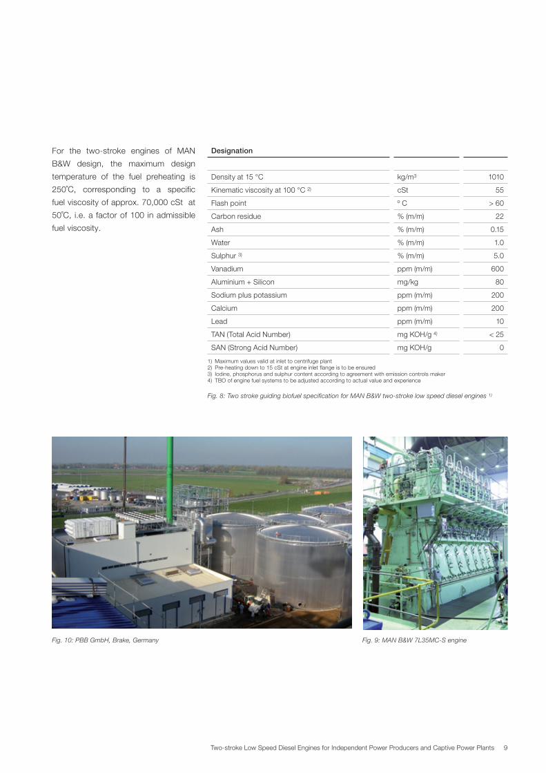
Fig. 8 shows the Guiding Biofuel Speci-
fication for MAN B&W two-stroke low
speed diesel engines. The first MAN
B&W two-stroke low speed engine,
an MAN B&W 7L35MC-S running on
crude palm oil, see Fig. 9, was commis-
sioned by MAN Diesel’s Polish licensee
H. Cegielski – Poznan S.A. in Brake,
Germany, at the beginning of 2009, see
Fig. 10.
Fuel flexibility
Most power plants built today are based
on the use of one or two fuels. Such fu-
els are typically natural gas or light fuels
for gas turbines, coal or heavy fuel for
steam turbines and diesel oil, heavy fuel
oil or natural gas for diesel engines.
The two-stroke low speed diesel en-
gines of MAN B&W design are able to
run on virtually any commercially avail-
able liquid or gaseous fuel.
Fig. 7 shows a typical guiding fuel oil
specification of today for such engines.
The basic data are dictated by the lo-
gistics of the marine market, which re-
quire that the fuel can be transported
to the ship. This requirement does not,
in principle, apply to stationary plants
which can be placed close to the
source of energy and connected to it by
a pipe which is heated by waste heat
from the engine.
Various types of refinery waste can thus
be used in low speed diesel engines.
Such fuel oil specifications are normally
quoted by the majority of diesel engine
designers on the market, regardless of
the number of strokes. Nevertheless, in
this connection, it should be noted that
most medium speed designers specify
a maximum design temperature of HFO
at injection in the range of 130-150˚C,
resulting in a maximum fuel viscosity of
700 cSt at 50˚C.
Designation Diesel engines
CIMAC-H55
Gas turbines
ASTM 2880
Density at 15 °C kg/m3 1010 876
Kinematic viscosity at 100 °C cSt 55 50
Flash point °C ≥ 60 66
Carbon residue % (mm) 22 0.35 3)
Ash % (mm) 0.15 0.03
Water % (mm) 1.0 1.0 2)
Sulphur % (mm) 5.0 1.0
Vanadium ppm (mm) 600 0.5-2
Aluminium + Silicon mg/kg 80 (10)
API gravity (min) °API 1) 35
Sodium plus potassium ppm (mm) 200 1
Calsium ppm (mm) 200 1
Lead ppm (mm) 10 10
1) experience, no limittations in official specificationa2) incl. sediment3) on 10% destillatiion
Fig. 7: Diesel engine and gas turbine liquid fuel specication
9Two-stroke Low Speed Diesel Engines for Independent Power Producers and Captive Power Plants
For the two-stroke engines of MAN
B&W design, the maximum design
temperature of the fuel preheating is
250˚C, corresponding to a specific
fuel viscosity of approx. 70,000 cSt at
50˚C, i.e. a factor of 100 in admissible
fuel viscosity.
Fig. 8: Two stroke guiding biofuel specification for MAN B&W twostroke low speed diesel engines 1)
Fig. 9: MAN B&W 7L35MCS engineFig. 10: PBB GmbH, Brake, Germany
Designation
Density at 15 °C kg/m3 1010
Kinematic viscosity at 100 °C 2) cSt 55
Flash point º C > 60
Carbon residue % (m/m) 22
Ash % (m/m) 0.15
Water % (m/m) 1.0
Sulphur 3) % (m/m) 5.0
Vanadium ppm (m/m) 600
Aluminium + Silicon mg/kg 80
Sodium plus potassium ppm (m/m) 200
Calcium ppm (m/m) 200
Lead ppm (m/m) 10
TAN (Total Acid Number) mg KOH/g 4) < 25
SAN (Strong Acid Number) mg KOH/g 0
1) Maximum values valid at inlet to centrifuge plant2) Pre-heating down to 15 cSt at engine inlet flange is to be ensured3) Iodine, phosphorus and sulphur content according to agreement with emission controls maker4) TBO of engine fuel systems to be adjusted according to actual value and experience
10 Two-stroke Low Speed Diesel Engines for Independent Power Producers and Captive Power Plants
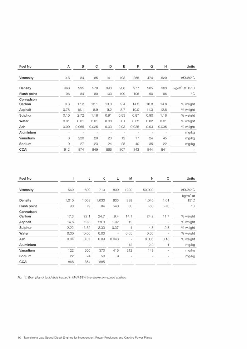
Fuel No A B C D E F G H Units
Viscosity 3.8 84 85 141 198 255 470 520 cSt/50°C
Density 968 995 970 993 938 977 985 983 kg/m3 at 15°C
Flash point 98 84 80 103 100 106 90 95 °C
Conradson Carbon 0.3 17.2 12.1 13.3 9.4 14.5 16.8 14.8 % weight
Asphalt 0.78 15.1 8.9 9.2 3.7 10.0 11.3 12.8 % weight
Sulphur 0.10 2.72 1.16 0.91 0.83 0.87 0.90 1.18 % weight
Water 0.01 0.01 0.01 0.00 0.01 0.02 0.02 0.01 % weight
Ash 0.00 0.065 0.025 0.03 0.03 0.025 0.03 0.035 % weight
Aluminium - - - - - - - - mg/kg
Vanadium 0 220 20 23 12 17 24 45 mg/kg
Sodium 0 27 23 24 25 40 35 22 mg/kg
CCAI 912 874 849 866 807 843 844 841 -
Fuel No I J K L M N O Units
Viscosity 560 690 710 800 1200 50,000 - cSt/50°C
Density 1,010 1,008 1,030 935 998 1,040 1.01kg/m3 at
15°C
Flash point 90 79 84 >40 80 >60 >70 °C
Conradson Carbon 17.3 22.1 24.7 9.4 14,1 24.2 11.7 % weight
Asphalt 14.6 19.3 29.0 1.02 12 - - % weight
Sulphur 2.22 3.52 3.30 0.37 4 4.8 2.8 % weight
Water 0.00 0.00 0.00 - 0,65 0.05 - % weight
Ash 0.04 0.07 0.09 0.043 - 0.035 0.18 % weight
Aluminium - - - - 12 2.0 1 mg/kg
Vanadium 122 300 370 415 312 149 - mg/kg
Sodium 22 24 50 9 - - - mg/kg
CCAI 868 864 885 - - - - -
Fig. 11: Examples of liquid fuels burned in MAN B&W twostroke lowspeed engines
11Two-stroke Low Speed Diesel Engines for Independent Power Producers and Captive Power Plants
Fig. 11 shows examples of liquid fuels
burned or tested successfully in MAN
B&W two-stroke low speed diesel en-
gines. Fig. 12 shows the similar data for
gaseous fuels.
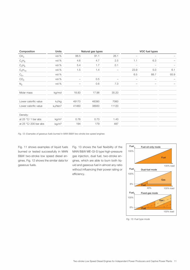
Fig. 13 shows the fuel flexibility of the
MAN B&W ME-GI-S type high-pressure
gas injection, dual fuel, two-stroke en-
gines, which are able to burn both liq-
uid and gaseous fuel in almost any ratio
without influencing their power rating or
efficiency.
Composition Units Natural gas types VOC fuel types
CH4 vol.% 88.5 91.1 26.1 – – –
C2H6 vol.% 4.6 4.7 2.5 1.1 6.3 –
C3H8 vol.% 5.4 1.7 0.1 – – –
C4H10 vol.% 1.5 1.4 – 23.9 5.0 6.1
C5+ vol.% 6.5 88.7 93.9
CO2 vol.% – 0.5 – – – –
N2 vol.% – 0.6 7.3 – – –
Molar mass kg/mol 18.83 17.98 35.20
Lower calorific value kJ/kg 49170 48390 7060
Lower calorific value kJ/Nm3 41460 38930 11120
Density:
at 25 °C/ 1 bar abs kg/m3 0.76 0.73 1.43
at 25 °C/ 200 bar abs kg/m3 194 179 487
Fig. 12: Examples of gaseous fuels burned in MAN B&W twostroke lowspeed engines
Gas
100% load40%Fuel
Fuel
100%
8%
Dual-fuel mode
100% load
Fuel
Fuel
100%
100% loadFuel
Gas
Fuel
100%
8%
Fixed-gas mode
Fuel-oil-only mode
Fig. 13: Fuel type mode
12 Two-stroke Low Speed Diesel Engines for Independent Power Producers and Captive Power Plants
Emissions
In response to the increasing demand
for environmental protection, the plants
– based on MAN B&W low speed en-
gines – can be delivered with internal
and external controls to comply with
virtually any emission restriction re-
quirements, including the World Bank
Guidelines for diesel-driven plants.
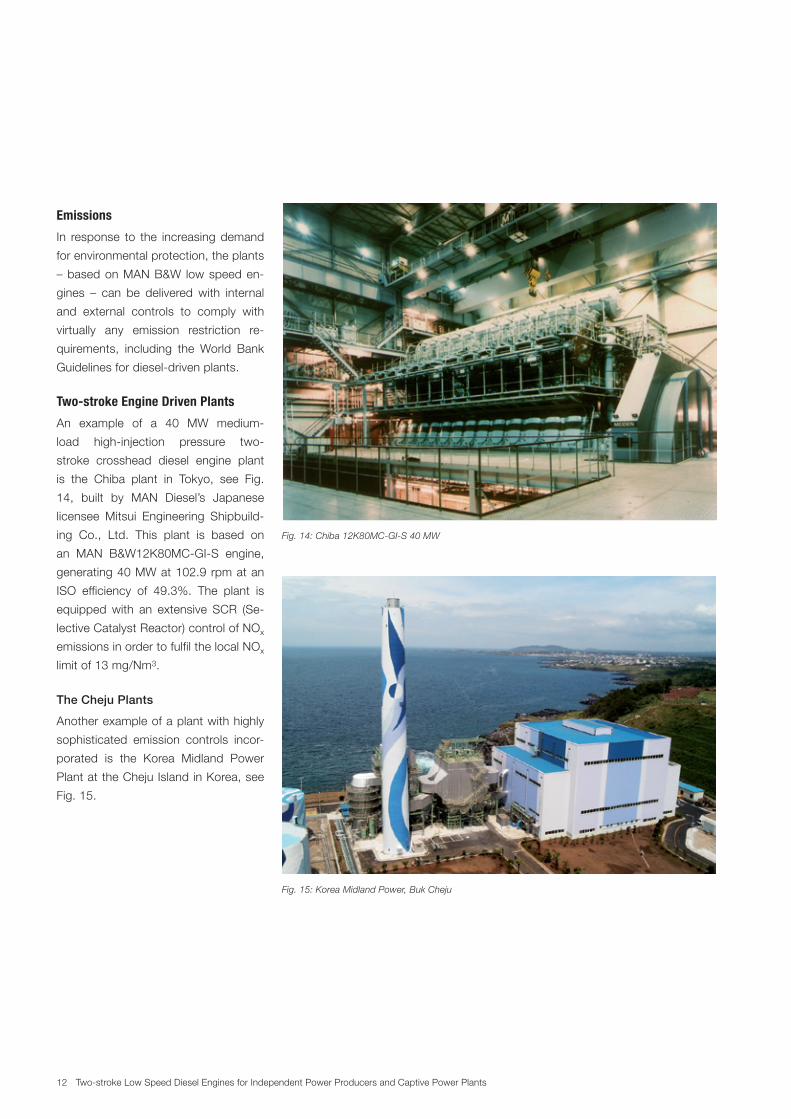
Two-stroke Engine Driven Plants
An example of a 40 MW medium-
load high-injection pressure two-
stroke crosshead diesel engine plant
is the Chiba plant in Tokyo, see Fig.
14, built by MAN Diesel’s Japanese
licensee Mitsui Engineering Shipbuild-
ing Co., Ltd. This plant is based on
an MAN B&W12K80MC-GI-S engine,
generating 40 MW at 102.9 rpm at an
ISO efficiency of 49.3%. The plant is
equipped with an extensive SCR (Se-
lective Catalyst Reactor) control of NOx
emissions in order to fulfil the local NOx
limit of 13 mg/Nm3.
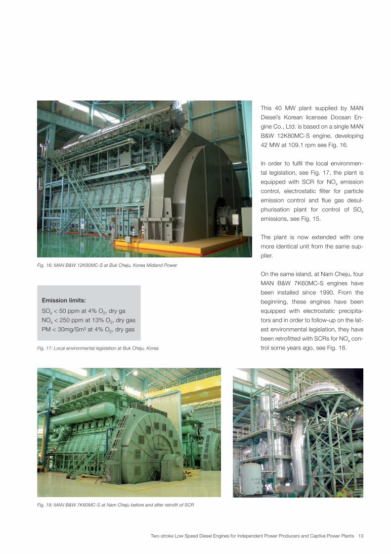
The Cheju Plants
Another example of a plant with highly
sophisticated emission controls incor-
porated is the Korea Midland Power
Plant at the Cheju Island in Korea, see
Fig. 15.
Fig. 14: Chiba 12K80MCGIS 40 MW
Fig. 15: Korea Midland Power, Buk Cheju
13Two-stroke Low Speed Diesel Engines for Independent Power Producers and Captive Power Plants
This 40 MW plant supplied by MAN
Diesel’s Korean licensee Doosan En-
gine Co., Ltd. is based on a single MAN
B&W 12K80MC-S engine, developing
42 MW at 109.1 rpm see Fig. 16.
In order to fulfil the local environmen-
tal legislation, see Fig. 17, the plant is
equipped with SCR for NOx emission
control, electrostatic filter for particle
emission control and flue gas desul-
phurisation plant for control of SOx
emissions, see Fig. 15.
The plant is now extended with one
more identical unit from the same sup-
plier.
On the same island, at Nam Cheju, four
MAN B&W 7K60MC-S engines have
been installed since 1990. From the
beginning, these engines have been
equipped with electrostatic precipita-
tors and in order to follow-up on the lat-
est environmental legislation, they have
been retrofitted with SCRs for NOx con-
trol some years ago, see Fig. 18.
Emission limits:
SOx < 50 ppm at 4% O2, dry ga
NOx < 250 ppm at 13% O2, dry gas
PM < 30mg/Sm3 at 4% O2, dry gas
Fig. 16: MAN B&W 12K80MCS at Buk Cheju, Korea Midland Power
Fig. 18: MAN B&W 7K60MCS at Nam Cheju before and after retrofit of SCR
Fig. 17: Local environmental legislation at Buk Cheju, Korea
14 Two-stroke Low Speed Diesel Engines for Independent Power Producers and Captive Power Plants
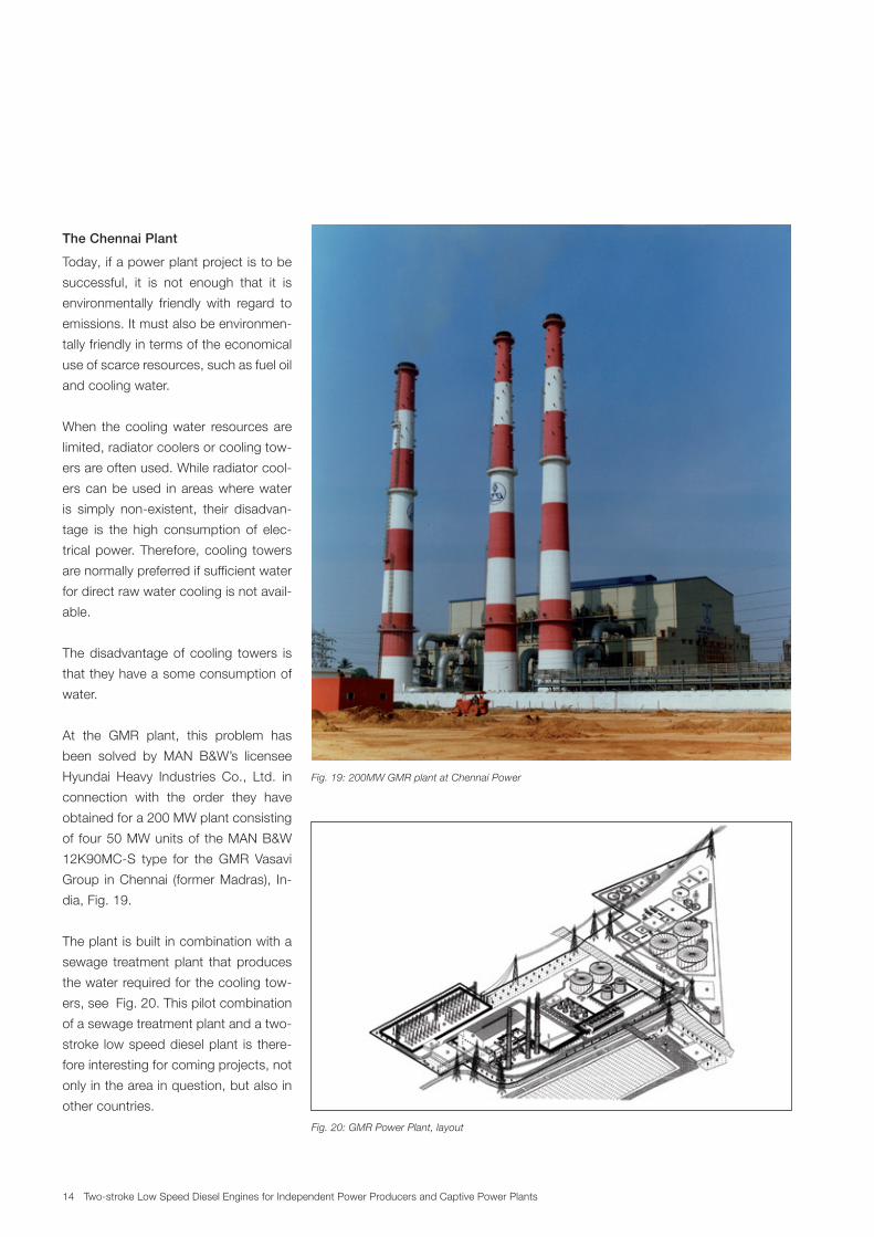
The Chennai Plant
Today, if a power plant project is to be
successful, it is not enough that it is
environmentally friendly with regard to
emissions. It must also be environmen-
tally friendly in terms of the economical
use of scarce resources, such as fuel oil
and cooling water.
When the cooling water resources are
limited, radiator coolers or cooling tow-
ers are often used. While radiator cool-
ers can be used in areas where water
is simply non-existent, their disadvan-
tage is the high consumption of elec-
trical power. Therefore, cooling towers
are normally preferred if sufficient water
for direct raw water cooling is not avail-
able.
The disadvantage of cooling towers is
that they have a some consumption of
water.
At the GMR plant, this problem has
been solved by MAN B&W’s licensee
Hyundai Heavy Industries Co., Ltd. in
connection with the order they have
obtained for a 200 MW plant consisting
of four 50 MW units of the MAN B&W
12K90MC-S type for the GMR Vasavi
Group in Chennai (former Madras), In-
dia, Fig. 19.
The plant is built in combination with a
sewage treatment plant that produces
the water required for the cooling tow-
ers, see Fig. 20. This pilot combination
of a sewage treatment plant and a two-
stroke low speed diesel plant is there-
fore interesting for coming projects, not
only in the area in question, but also in
other countries.
Fig. 19: 200MW GMR plant at Chennai Power
Fig. 20: GMR Power Plant, layout
15Two-stroke Low Speed Diesel Engines for Independent Power Producers and Captive Power Plants
Conclusion
As shown, the two-stroke low speed
diesel engines of MAN B&W design are
a viable option to be investigated and
chosen by owners anywhere where re-
liable fuel-efficient diesel plants are re-
quired, especially if the fuel is of a poor
quality and available in scarce amounts.
The future development of such en-
gines will be dictated by the market,
in particular by the future fuel oil prices
and qualities, and the trend seems to
point in the direction of even more ef-
ficient, ever larger and more environ-
mentally friendly units.


MAN Diesel & TurboTeglholmsgade 412450 Copenhagen SV, DenmarkPhone +45 33 85 11 00Fax +45 33 85 10 [email protected]
MAN Diesel & Turbo – a member of the MAN Group
All data provided in this document is non-binding. This data serves informational purposes only and is especially not guaranteed in any way. Depending on the subsequent specific individual projects, the relevant data may be subject to changes and will be assessed and determined individually for each project. This will depend on the particular characteristics of each individual project, especially specific site and operational conditions. Copyright © MAN Diesel & Turbo. 5510-0000-00ppr Mdd 2012 Printed in Denmark
MAN Diesel & TurboTeglholmsgade 412450 Copenhagen SV, DenmarkPhone +45 33 85 11 00Fax +45 33 85 10 [email protected]
MAN Diesel & Turbo – a member of the MAN Group
All data provided in this document is non-binding. This data serves informational purposes only and is especially not guaranteed in any way. Depending on the subsequent specific individual projects, the relevant data may be subject to changes and will be assessed and determined individually for each project. This will depend on the particular characteristics of each individual project, especially specific site and operational conditions. Copyright © MAN Diesel & Turbo. 5510-0067-01ppr Aug 2013 Printed in Denmark