Embed Size (px)
Citation preview
7/29/2019 Tunnel intake
http://slidepdf.com/reader/full/tunnel-intake 1/25
Module
4
Hydraulic Structures forFlow Diversion and
StorageVersion2 CE IIT, Kharagpur

7/29/2019 Tunnel intake
http://slidepdf.com/reader/full/tunnel-intake 2/25
Lesson
9Reservoir Outlet Works
Version2 CE IIT, Kharagpur
7/29/2019 Tunnel intake
http://slidepdf.com/reader/full/tunnel-intake 3/25
Instructional objectives
On completion of this lesson, the student shall learn:
1. Functions of outlet works2. Classification of outlet works
3. Determination of design discharge and elevation of outlet works4. Choice of outlet works and their layout5. Components of outlet works6. Hydraulic design of outlet works
4.9.0 Introduction
Water from the reservoir of a dam is released through two principal types of structures:
1. Spillways, which are provided for storage and detention dams to release surpluswater or floodwater that cannot be contained in the allotted storage space, andfor diversion dams to bypass flows exceeding those turned into the diversionsystem.
2. Outlet works, which regulate or release water impounded by a dam. It canrelease incoming flows at a retarded rate, as does a detention dam; it can divertincoming flows into canals or pipelines, as does a diversion dam; or it canrelease stored waters at rates dictated by downstream needs, by evacuationconsiderations, or by a combination of multiple-purpose requirements.
Outlet works are so named because they release out water from the reservoir. Some of these are equipped with an Intake Structure if the water is fed into a canal or a conduitfor serving some specific purpose like meeting irrigation water requirement orhydropower generation, etc.
Occasionally, the outlet works may be placed at a level high enough to deliver water toa canal, while a bypass is extended to the river to furnish necessary flows below thedam. Such bypass flows may be required to satisfy prior-right uses downstream or tomaintain a live stream for abatement of stream pollution, preservation of aquatic life, orother purposes. Dams constructed to provide reservoirs principally for recreation or forfish and wildlife conservation require a fairly constant reservoir level. For such dams an
outlet works may be needed only to release the minimum flows necessary to maintain alive stream below the dam. In certain cases, the outlet works of a dam may be used inlieu of a service spillway combined with an auxiliary or secondary spillway. In such acase, the usual outlet works installation might be modified to include a bypass overflowso that the structure can serve as both an outlet works and a spillway.
An outlet work may act as a flood control regulator to release waters temporarily storedin flood control storage space or to deplete the storage of a reservoir in anticipation of
Version2 CE IIT, Kharagpur
7/29/2019 Tunnel intake
http://slidepdf.com/reader/full/tunnel-intake 4/25
flood inflows. Furthermore, the outlets may be used to empty the reservoir to permitinspection, to allow needed repairs, or to maintain the upstream face of the dam orother structures normally inundated. The outlets may also aid in lowering the reservoirstorage when controlling objectionable aquatic life in the reservoir is desired.Sometimes reservoirs are lowered and raised in a sequence to control the menace of
malaria.
4.9.1 Classification of outlet works
Outlet works structures can be classified according to their purpose, their physical andstructural arrangement, or their hydraulic operation. An outlet work that empties directlyinto a river could be designated a “river outlet”; one that discharges into a canal couldbe designated a “canal outlet”; and one that delivers water into a closed pipe systemcould be designated a “pressure pipe outlet.” An outlet work may be described
according to whether it consists of an open-channel or closed-conduit waterway, orwhether the closed waterway is a conduit in cut-and-cover or in a tunnel. An outletworks may also be classified according to its hydraulic operation: whether it is gated orungated or, for a closed conduit, whether it flows under pressure for part or all of itslength or only as a free flow waterway.
Reservoir outlet works facilities may also be divided as those provided in concretegravity dams or embankment dams. Outlet works through concrete gravity dams areusually called sluices while those through embankment dams are called conduits (if laidbelow an embankment dam or constructed by cut-and-cover procedure) or tunnels (if excavated through the abutment or foundation). Certain specific requirement of sluicesthrough concrete gravity dams and embankment dams are given below:
a. Concrete Gravity Dams. Generally, sluices that traverse through concrete gravitydams have rectangular cross sections and are short in comparison with conduitsthrough embankment dams of comparable height. Use of a number of small sluices, atone or more elevations provides flexibility in flow regulation and in quantity of waterreleased downstream. Sluices are controlled by gates at the upstream face and/or bygates or valves operated from a gallery in the interior of the dam. Sluices are usuallydesigned so that the outflow discharges onto the spillway face and/or directly into thestilling basin. When sluices traverse through non-overflow sections, a separate energydissipator must be provided.
b. Embankment Dams. Conduits and/or tunnels for embankment dams may havecircular, rectangular, horseshoe, or oblong cross sections and their length is primarilydetermined by the base width of the embankment. Due to the greater length, it is usuallymore economical to construct a single large conduit than a number of small conduits.Conduits should be tunneled through the abutment as far from the embankment aspracticable, or placed in an open cut through rock in the abutment or on the valley floor.Gates and/or valves in an intake tower in the reservoir, in a central control shaft in theabutment or embankment, or at the outlet portal are used to control the flow. Generally,
Version2 CE IIT, Kharagpur
7/29/2019 Tunnel intake
http://slidepdf.com/reader/full/tunnel-intake 5/25
placement of the control device at the outlet portal should be avoided when the conduitpasses through the embankment due to the inherent dangers of a possible rupture of aconduit subject to full reservoir head. Diversion during construction or reservoirevacuation requirements, especially on large streams, may govern the size andelevation of the conduit(s).
4.9.2 Functions of outlet works
1. Flood Control. Flood control outlets are designed for relatively large capacitieswhere close regulation of flow is less important than are other requirements.Although control of the outflow by gates is usually provided, the conduits may beungated, in which case the reservoir is low or empty except in time of flood. Whenlarge discharges must he released under high heads, the design of gates, waterpassages, and energy dissipator should be carefully developed. Multilevel release
provisions are often necessary for water quality purposes.
2. Navigation. Reservoirs that store water for subsequent release to downstreamnavigation usually discharge at lower capacity than flood control reservoirs, but theneed for close regulation of the flow is more important. The navigation season oftencoincides with the season of low rainfall, and close regulation aids in theconservation of water. Outlet works that control discharges for navigation purposesare required to operate continuously over long periods of time. The designer shouldconsider the greater operation and maintenance problems involved in continuousoperation.
3. Irrigation. The gates or valves for controlling irrigation flows are often basicallydifferent from those used for flood control due to the necessity for close regulationand conservation of water in arid regions. Irrigation discharge facilities are normallymuch smaller in size than flood regulation outlets. The irrigation outlet sometimesdischarges into a canal or conduit rather than to the original riverbed. These canalsor conduits are usually at a higher level than the bed of the stream. This has beenimplemented for the canal off-taking from the Sardar Sarovar Dam on RiverNarmada. At other times, irrigation releases are let down to the river from where abarrage downstream picks up the flow and diverts it into an irrigation canal. Forexample, Bhakra Dam and Nangal Barrage on River Sutlej, Maithon dam andDurgapur Barrage on River Damodar and Hirakud Dam and Mahanadi Barrage onRiver Mahanadi etc. were built in conjunction with one another to serve a similarpurpose.
4. Water Supply . Municipal water supply intakes are sometimes provided in damsbuilt primarily for other purposes. Such problems as future water supplyrequirements and peak demands for a municipality or industry should be determinedin cooperation with engineers representing local interests. Reliability of service andquality of water are of prime importance in water supply problems. Multiple intakes
Version2 CE IIT, Kharagpur
7/29/2019 Tunnel intake
http://slidepdf.com/reader/full/tunnel-intake 6/25
and control mechanisms are often installed to assure reliability, to enable the waterto be drawn from any selected reservoir level to obtain water of a desiredtemperature, and/or to draw from a stratum relatively free from silt or algae or otherundesirable contents. Ease of maintenance repair without interruption of service is of primary importance. An emergency closure gate for priority use by the resident
engineer is required for water supply conduits through the dam.
5. Power. For generation of hydropower, intake structures direct water from thereservoir into the penstock or power conduit. Gates or valves are used to shut off theflow of water to permit emergency unit shutdown or turbine and penstockmaintenance. Racks or screens prevent trash and debris from entering the turbineunits. Where the powerhouse is integral with the dam, the intake is part of the damstructure. Where the powerhouse is not part of the dam, a separate intake structuremust be provided. Projects that are required to use water at a selected temperaturemust have multi-level intakes in order to control inlet water quality by mixing watersobtained from different levels.
6. Low-Flow Requirements. Continuous low-flow releases are required at some damsto satisfy environmental objectives, water supply, downstream water rights, etc. Tomeet these requirements multilevel intakes, skimmer weirs, or other provisions mustbe incorporated separately or in combination with other functions of the outlet worksfacility. Special provisions for these purposes have to be incorporated in concretegravity dam non-overflow sections. Embankment dams with mid-tunnel controlshafts also require special considerations for low-flow releases.
7. Diversion. Flood control outlets may be used for total or partial diversion of thestream from its natural channel during construction of the dam. Such use isespecially adaptable for earth dams.
8. Drawdown. Requirements for low-level discharge facilities for drawdown of impoundments may also provide flexibility in future project operation for anticipatedneeds, such as major repairs of the structure, environmental controls, or changes inreservoir regulation.
4.9.3 Determination of design discharge capacities
Outlet works are designed to release water at specific rates. These rates are dictated bydownstream needs, by flood control regulation, by storage considerations, by powergeneration needs (where the outlet works is used as the penstock for power plants),and by legal requirements. Delivery of irrigation water is usually determined from projector farm needs and is related to the consumptive use and to the special waterrequirements of the irrigation system. Delivery for domestic use can be similarlyestablished. Releases of flows to satisfy prior rights must generally be included withother needed releases. Minimum downstream flows for pollution abatement, fish
Version2 CE IIT, Kharagpur
7/29/2019 Tunnel intake
http://slidepdf.com/reader/full/tunnel-intake 7/25
preservation, and associated needs are often accommodated through other requiredreleases. A small bypass pipe is often used to provide these minimum releases. Thispipe usually originates at the gate chamber or in the downstream control structure,depending on the type of outlet works.
Irrigation outlet capacities are determined from reservoir operation studies. They must
be based on a consideration of a critical period of low runoff when reservoir storagesare low and daily irrigation demands are at their peak. The most critical draft from thereservoir, considering such demands (commensurate with remaining reservoir storage)together with prior rights and other needed releases, generally determines the minimumirrigation outlet capacity. These requirements are stated in terms of discharge at either agiven reservoir content or a given water surface elevation. Evacuation of water stored inan allocated flood control storage space of a reservoir can be accomplished through agated spillway at the higher reservoir levels or through an outlet at the lower levels.
Flood control releases generally can be combined with the irrigation releases if theoutlet empties into a river instead of into a canal. The capacity of a flood control outletcan be determined by the required time of evacuation of the given storage space,considering the inflow into the reservoir during the evacuation. Combined flood controland irrigation releases ordinarily must not exceed the safe channel capacity of the riverdownstream from the dam and must allow for all anticipated inflows immediately belowthe dam. These inflows may be natural run-offs, or the results of releases from storagedevelopments along the river or from developments on tributaries emptying into theriver.
If an outlet is to serve as a service spillway in releasing surplus inflows from thereservoir, the discharge required for this purpose may determine the outlet capacity.Similarly, the minimum outlet capacity can be determined by the discharge and the timerequired to empty the reservoir for inspection, maintenance, repair, or emergency
drawdown. Here again, the inflow into the reservoir during the emptying period must beconsidered. The capacity at low reservoir level should be at least equal to the averageinflow expected during the maintenance or repair period. It can, of course, be assumedthat required repair will be delayed until service demands are light and that repairs willbe made during low inflow and during seasons favorable to such construction.
An outlet works cut-and-cover conduit or tunnel is often used to divert the river flowduring the construction period, precluding supplementary installations for that purpose. The outlet structure size dictated by this use, rather than the size dictated by ordinaryoutlet works requirements, may determine the final outlet works capacity. A diversionbypass pipe may be required to satisfy downstream requirements during placement of second-stage concrete and gates in the outlet works.
4.9.4 Position (elevation) of outlet works in relation to reservoirstorage levels
The establishment of the intake level and the elevations of the outlet controls and theconveyance passageway, as they relate to the reservoir storage levels, are influenced
Version2 CE IIT, Kharagpur
7/29/2019 Tunnel intake
http://slidepdf.com/reader/full/tunnel-intake 8/25
by many factors. Primarily, to attain the required discharge capacity, the outlet must beplaced sufficiently below the minimum reservoir operating level to provide the headrequired for outlet works flows.
Outlet works for small detention dams are generally constructed near riverbed levelbecause permanent storage space, except for silt retention, is ordinarily not provided.
These outlet works may be ungated to retard the outflow while the reservoir temporarilystores the bulk of the flood runoff, or they may be gated to regulate the releases of thetemporarily stored waters. If the purpose of the dam is only to raise the reservoir anddivert incoming flows at low heads, the main outlet works generally should be an intakeor regulating structure at a high level. A sluiceway or small bypass outlet should also beprovided to furnish water to the river downstream or to drain the water from behind thedam during off-season periods. Dams that impound water for irrigation, for domesticuse, or for other conservation purposes, must have outlet works low enough to draw thereservoir down to the bottom of the allocated storage space; however, the outlet worksmay be placed above the riverbed, depending on the established minimum reservoirstorage level. It is common practice to make an allowance in a storage reservoir for
inactive storage to accommodate sediment deposition, for fish and wildlife conservation,and for recreation. The positioning of the intake sill then becomes an importantconsideration; it must be high enough to prevent interference from the sedimentdeposits, but at the same time, low enough to permit either a partial or a completedrawdown below the top of the inactive storage.
Where an outlet is placed at riverbed level to accommodate the construction diversionplan or to drain the reservoir, the operating sill may be placed at a higher level toprovide a sediment and debris basin and other desired inactive storage space, or theintake may be designed to permit raising the sill as sediment accumulates. Duringconstruction, a temporary diversion opening may be formed in the base of the intake tohandle diversion flows. Later, this opening may be plugged. For emptying the reservoir,a bypass around the intake may be installed at riverbed level. This bypass may eitherempty into the lower portion of the conduit or pass under it. Water can be delivered to acanal at a higher level by a pressure riser pipe connecting the conduit to the canal.
4.9.5 Choice of outlet works and their layout
The layout of an outlet work is influenced by many conditions relating to the hydraulicrequirements, to the site adaptability, to the interrelation of the outlet works and theconstruction procedures, and to the other appurtenances of the development. Thus, an
outlet work leading to a high-level canal or into a closed pipeline might differ from oneemptying into the river. Similarly, a scheme in which the outlet works is used fordiversion might vary from one where diversion is effected by other means. In certaininstances, the proximity of the spillway may permit combining some of the outlet worksand spillway components in a single structure. For example, the spillway and outletworks layout might be arranged so that discharges from both empty into a commonstilling basin.
Version2 CE IIT, Kharagpur
7/29/2019 Tunnel intake
http://slidepdf.com/reader/full/tunnel-intake 9/25
The topography and geology of a site may have a great influence on the layoutselection. Some sites may be suited only for a cut-and-cover conduit type of outletworks; whereas, at other sites, either a cut-and-cover conduit or a tunnel may beselected. Unfavorable foundation geology, such as deep over-burdens or inferiorfoundation rock, precludes the selection of a tunnel scheme. On the other hand, sites in
narrow canyons with steep abutments may make a tunnel outlet the only choice.Because of confined working space and excessive costs where hand-constructionmethods must be used, building a tunnel smaller than about 2 metre in diameter is notpracticable. However, a cut-and-cover conduit can be built to almost any size if it isprecast or cast-in-place with the inside bore formed by a pre-fabricated liner. Thus, theminimum size dictated by construction conditions, more than the size dictated byhydraulic requirements, influences the choice of either the cut-and-cover conduit or thetunnel scheme. The amount of load to be taken by a conduit will also affect this choice.
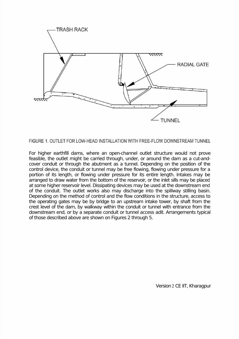
The outlet works for a low dam, whether it is to divert water into a canal or release it tothe river, often consists of an open-channel or cut-and-cover structure at the damabutment. The structure may consist of a conventional open flume or rectangular
channel with a gate similar to that used for ordinary spillway installations, or it may beregulated by a submerged gate placed to close off openings in a curtain or headwall.Where the outlet is to be placed through a low earthfill embankment, a closed structuremay be used. This structure may consist of single or multiple units of buried pipe or boxculverts placed through or under the embankment. Flow for such an installation couldbe controlled by gates placed at the inlet or at an intermediate point along the conduit,such as at the crest of the embankment, where a shaft would be provided for gateoperation. Downstream from the control structure, the channel would continue to thecanal or to the river where, depending on the exit velocities, a stilling device. Figure lshows typical installations of the arrangements described above.
Version2 CE IIT, Kharagpur
7/29/2019 Tunnel intake
http://slidepdf.com/reader/full/tunnel-intake 10/25
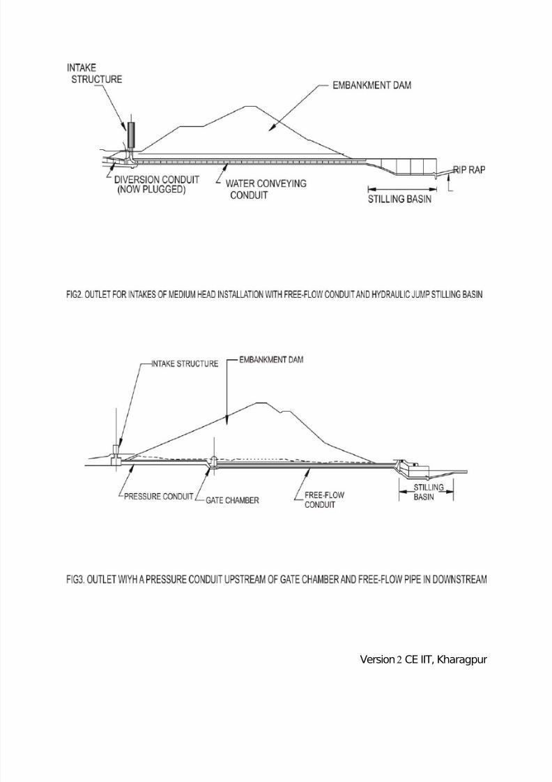
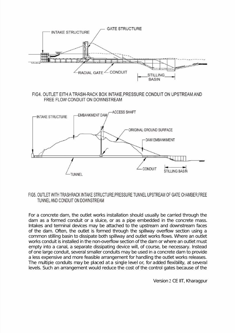
For higher earthfill dams, where an open-channel outlet structure would not provefeasible, the outlet might be carried through, under, or around the dam as a cut-and-cover conduit or through the abutment as a tunnel. Depending on the position of thecontrol device, the conduit or tunnel may be free flowing, flowing under pressure for aportion of its length, or flowing under pressure for its entire length. Intakes may bearranged to draw water from the bottom of the reservoir, or the inlet sills may be placedat some higher reservoir level. Dissipating devices may be used at the downstream endof the conduit. The outlet works also may discharge into the spillway stilling basin.Depending on the method of control and the flow conditions in the structure, access tothe operating gates may be by bridge to an upstream intake tower, by shaft from thecrest level of the dam, by walkway within the conduit or tunnel with entrance from thedownstream end, or by a separate conduit or tunnel access adit. Arrangements typicalof those described above are shown on Figures 2 through 5.
Version2 CE IIT, Kharagpur
7/29/2019 Tunnel intake
http://slidepdf.com/reader/full/tunnel-intake 11/25
Version2 CE IIT, Kharagpur
7/29/2019 Tunnel intake
http://slidepdf.com/reader/full/tunnel-intake 12/25
For a concrete dam, the outlet works installation should usually be carried through thedam as a formed conduit or a sluice, or as a pipe embedded in the concrete mass.Intakes and terminal devices may be attached to the upstream and downstream facesof the dam. Often, the outlet is formed through the spillway overflow section using acommon stilling basin to dissipate both spillway and outlet works flows. Where an outletworks conduit is installed in the non-overflow section of the dam or where an outlet mustempty into a canal, a separate dissipating device will, of course, be necessary. Insteadof one large conduit, several smaller conduits may be used in a concrete dam to providea less expensive and more feasible arrangement for handling the outlet works releases. The multiple conduits may be placed at a single level or, for added flexibility, at severallevels. Such an arrangement would reduce the cost of the control gates because of the
Version2 CE IIT, Kharagpur
7/29/2019 Tunnel intake
http://slidepdf.com/reader/full/tunnel-intake 13/25
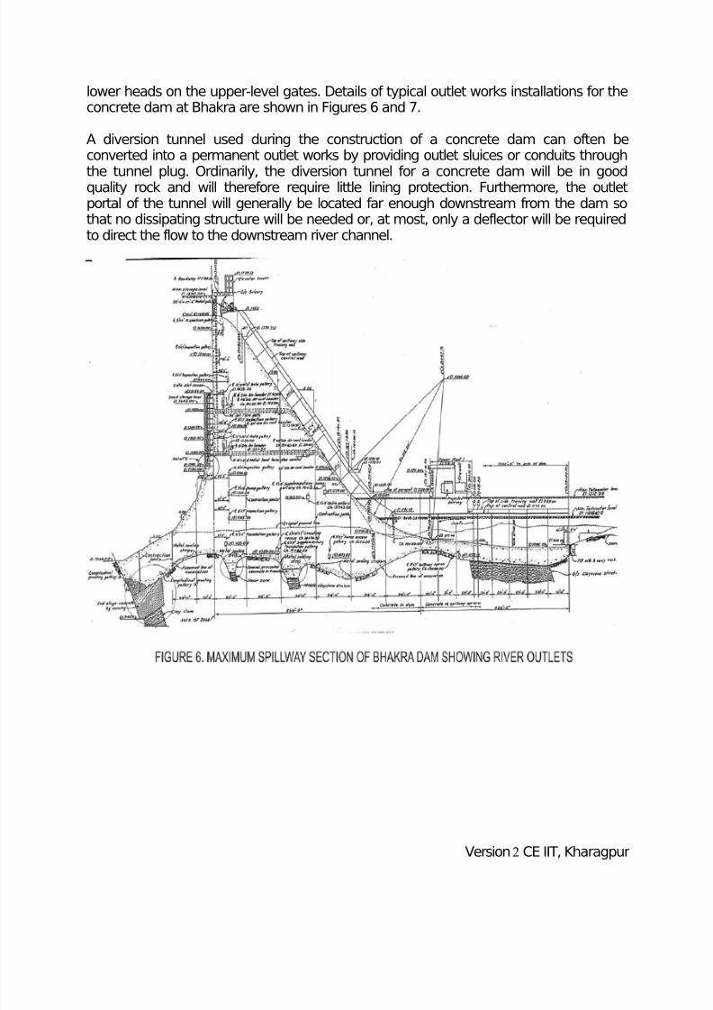
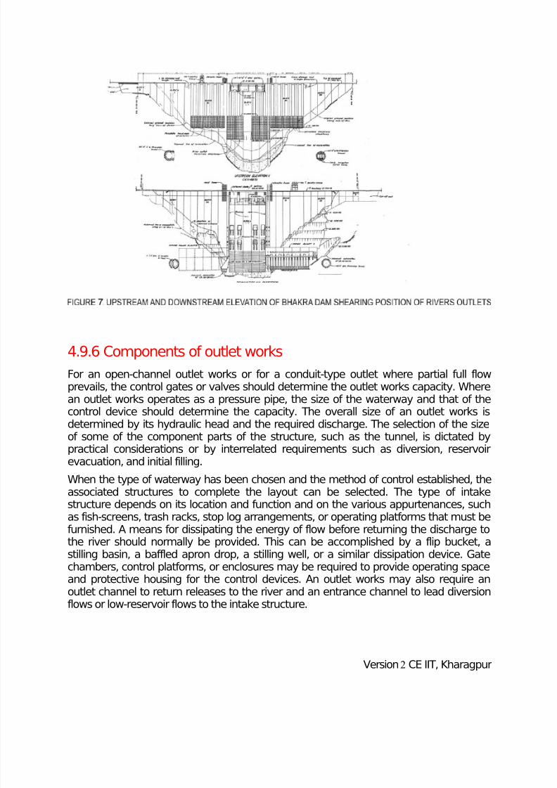
lower heads on the upper-level gates. Details of typical outlet works installations for theconcrete dam at Bhakra are shown in Figures 6 and 7.
A diversion tunnel used during the construction of a concrete dam can often beconverted into a permanent outlet works by providing outlet sluices or conduits through
the tunnel plug. Ordinarily, the diversion tunnel for a concrete dam will be in goodquality rock and will therefore require little lining protection. Furthermore, the outletportal of the tunnel will generally be located far enough downstream from the dam sothat no dissipating structure will be needed or, at most, only a deflector will be requiredto direct the flow to the downstream river channel.
Version2 CE IIT, Kharagpur
7/29/2019 Tunnel intake
http://slidepdf.com/reader/full/tunnel-intake 14/25
4.9.6 Components of outlet works
For an open-channel outlet works or for a conduit-type outlet where partial full flowprevails, the control gates or valves should determine the outlet works capacity. Wherean outlet works operates as a pressure pipe, the size of the waterway and that of the
control device should determine the capacity. The overall size of an outlet works isdetermined by its hydraulic head and the required discharge. The selection of the sizeof some of the component parts of the structure, such as the tunnel, is dictated bypractical considerations or by interrelated requirements such as diversion, reservoirevacuation, and initial filling.
When the type of waterway has been chosen and the method of control established, theassociated structures to complete the layout can be selected. The type of intakestructure depends on its location and function and on the various appurtenances, suchas fish-screens, trash racks, stop log arrangements, or operating platforms that must befurnished. A means for dissipating the energy of flow before returning the discharge tothe river should normally be provided. This can be accomplished by a flip bucket, a
stilling basin, a baffled apron drop, a stilling well, or a similar dissipation device. Gatechambers, control platforms, or enclosures may be required to provide operating spaceand protective housing for the control devices. An outlet works may also require anoutlet channel to return releases to the river and an entrance channel to lead diversionflows or low-reservoir flows to the intake structure.
Version2 CE IIT, Kharagpur
7/29/2019 Tunnel intake
http://slidepdf.com/reader/full/tunnel-intake 15/25
Tunnels
Because of its inherent advantages, a tunnel outlet works is preferred where abutmentand foundation conditions permit its use and it is more economical than the other typesof outlet works. A tunnel is not in direct contact with the dam embankment and,therefore, provides a much safer and more durable layout than can be achieved with a
cut-and-cover conduit. Little foundation settlement, differential movement, and structuraldisplacement is experienced with a tunnel that has been bored through competentabutment material, and seepage along the outer surfaces of the tunnel lining or leakageinto the material surrounding the tunnel is less serious. Furthermore, it is less likely thatfailure of some portion of a tunnel would cause failure of the dam than the failure of acut-and-cover conduit that passes under or through the dam.
Cut-and-Cover Conduits
If a closed conduit is to be provided and foundation conditions are not suitable for atunnel, or if the required size of the waterway is too small to justify the minimum sized
tunnel, a cut-and-cover conduit should be used. Because this type of conduit passesthrough or under the dam, conservative and safe designs must be used. Numerousfailures of earthfill dams caused by improperly designed or constructed cut-and-coveroutlet conduits have demonstrated the need for conservative procedures.
Control Devices
Selection of the outlet works arrangement should be based on the use of commerciallyavailable gates and valves or relatively simple gate designs where possible. The use of special devices that involve expensive design and fabrication costs should be avoided.Cast iron slide gates, which may be used for control and guard gates, are available forboth rectangular and circular openings and for design heads up to about 15 metre.However, higher head installations require special gate designs. Simple radial gates areavailable for ordinary surface installations, and top-seal radial gates can be securedfrom manufacturers on the basis of simple designs and specifications. For low heads upto about 15 metre, commercial gate and butterfly valves are suitable for control at thedownstream end of pressure pipes if they are designed to operate under free dischargeconditions with the jet well aerated all around. Gate and butterfly valves are alsosuitable for use as inline guard valves and can be adapted for inline control valves if airventing and adequate aeration of the discharge jet are provided immediatelydownstream from the valve.
The control gate for an outlet works may be placed at the upstream end of the conduit,
at an intermediate point along its length, or at the lower end of the structure. Where flowfrom a control gate is released directly into the open as free discharge, only that portionof the conduit upstream from the gate is under pressure. Where a control gate or valveis placed at the lower end of the structure, full internal pressure should be considered inthe design of the conduit tunnel or pipe. However, when a control discharges into a free-flow conduit, the location of the control gate becomes important in the design of theoutlet. Upstream gate controls for conduits are generally placed in a tower structure withthe gate hoists mounted on the operating deck (Figure 2). With this arrangement, the
Version2 CE IIT, Kharagpur
7/29/2019 Tunnel intake
http://slidepdf.com/reader/full/tunnel-intake 16/25
tower must extend above the maximum water surface. If controls are to be located atsome intermediate point along the conduit, high-pressure gates, slide gates, and top-seal radial gates may be used. These controls may be located in a wet-well shaft thatextends vertically from the conduit level to the crest of the dam. Typical arrangements of these installations are shown in Figures 1 to 4.
Intake Structures
In addition to forming the entrance to the outlet works, an intake structure mayaccommodate control devices. It also supports necessary auxiliary appurtenances (suchas trashracks, fishscreens, and bypass devices), and it may include temporary diversionopenings and provisions for installation of bulkhead or stoplog closure devices. Intakestructures may appear in many forms. The type of intake structure selected should bebased on several factors: the functions it must serve, the range in reservoir head underwhich it must operate, the discharge it must handle, the frequency of reservoirdrawdown, the trash conditions in the reservoir (which will determine the need for or thefrequency of cleaning of the trashracks), reservoir wave action that could affect the
stability, and other similar considerations. Depending on its function, an intake structuremay be either submerged or extended in the form of a tower above the maximumreservoir water surface. A tower must be provided if the controls are placed at theintake, or if an operating platform is needed for trash removal, maintaining and cleaningfish-screens, or installing stoplogs. Where the structure serves only as an entrance tothe outlet conduit and where trash cleaning is ordinarily not required, a submergedstructure may be adopted.
The necessity for trashracks on an outlet works depends on the size of the sluice orconduit, the type of control device used, the nature of the trash burden in the reservoir,the use of the water, the need for excluding small trash from the outflow, and otherfactors. These factors determine the type of trashracks and the size of the openings.Where an outlet consists of a small conduit with valve controls, closely spaced trashbars are needed to exclude small trash. Where an outlet involves a large conduit withlarge slide-gate controls, the racks can be more widely spaced. If there is no danger of clogging or damage from small trash, a trashrack may consist simply of struts andbeams placed to exclude only larger trees and similarly sized floating debris. The rackarrangement should also be based on the accessibility for removing accumulated trash. Thus, a submerged rack that seldom will be dewatered must be more substantial thanone at or near the surface. Similarly, an outlet with controls at the entrance, where thegates can be jammed by trash protruding through the rack bars, must have a moresubstantial rack arrangement than one whose controls are not at the entrance.
Energy Dissipating Arrangements
The discharge from an outlet, whether of a gate valve, or free flow conduit, will emergeat a high velocity, usually in a nearly horizontal direction. If erosion-resistant bedrockexists at shallow depths, the flow may be discharged directly into the river. Otherwise, itshould be directed away from the toe of the dam by a deflector. Where erosion is to beminimized, a plunge basin may be excavated and lined with riprap or concrete. Whenmore energy dissipation is required for free flow conduits, the terminal structures
Version2 CE IIT, Kharagpur
7/29/2019 Tunnel intake
http://slidepdf.com/reader/full/tunnel-intake 17/25
described for spillways may be used. The hydraulic-jump basin is most often used forenergy dissipation of outlet works discharges. However, flow that emerges from theoutlet in the form of a free jet, as is the case for valve-controlled outlets of pressureconduits, must be directed onto the transition floor approaching the basin so it willbecome uniformly distributed before entering the basin. Otherwise, proper energy
dissipation will not be obtained.
Entrance and Outlet Channels
An entrance channel and an outlet channel are often required for a tunnel or cut-and-cover conduit layout. An entrance channel may be required to convey diversion flows toa conduit in an abutment or to deliver water to the outlet works intake during lowreservoir stage. And an outlet channel may be required to convey discharges from theend of the outlet works to the river downstream or to a canal.
4.9.7 Hydraulic design of outlets
The hydraulics of outlet works usually involves either open-channel (free) flow or fullconduit (pressure) flow. Analysis of open-channel flow in outlet works, either in an openwaterway or in a partly-full conduit, is based on the principle of steady nonuniform flowconforming to the law of conservation of energy. Full-pipe flow in closed conduits isbased on pressure flow, which involves a study of hydraulic losses to determine thetotal heads needed to produce the required discharges.
Three types of outlet works are briefly discussed below which are commonly provided inriver valley projects.
Sluices in concrete dams
Sluices are provided in the body of the dam to release regulated supplies of water for avariety of purposes which are briefly listed below:
1. River diversion2. Irrigation3. Generation of hydro-electric power4. Water supply for municipal or industrial uses5. To pass the flood discharge in conjunction with the spillway6. Flood control regulation to release water temporarily stored in flood control
storage space or to evacuate the storage in anticipation of flood inflows7. Depletion of the reservoir in order to facilitate inspection of the reservoir rim and
the upstream face of the dam for carrying out remedial measures, if necessary8. To furnish necessary flows for satisfying prior right uses downstream9. For maintenance of a live stream for abatement of stream polation, preservation
of aquatic life, etc.
Version2 CE IIT, Kharagpur
7/29/2019 Tunnel intake
http://slidepdf.com/reader/full/tunnel-intake 18/25
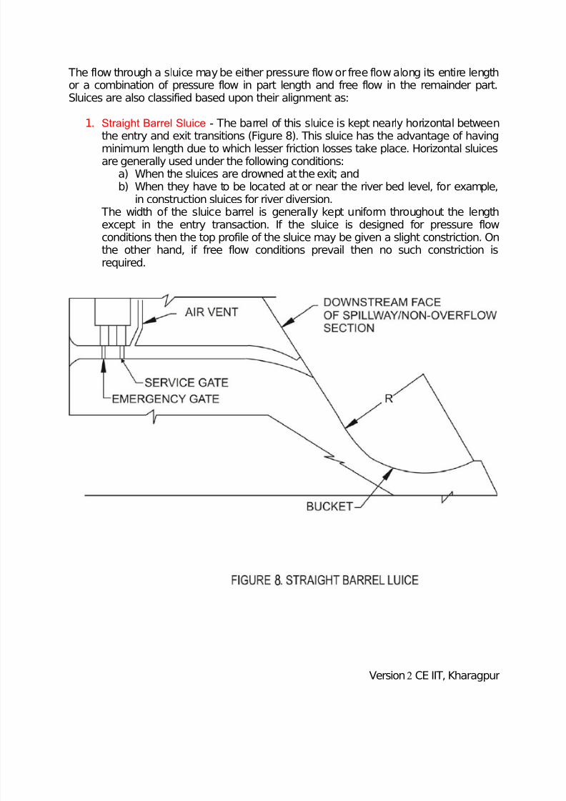
The flow through a sluice may be either pressure flow or free flow along its entire lengthor a combination of pressure flow in part length and free flow in the remainder part.Sluices are also classified based upon their alignment as:
1. Straight Barrel Sluice - The barrel of this sluice is kept nearly horizontal between
the entry and exit transitions (Figure 8). This sluice has the advantage of havingminimum length due to which lesser friction losses take place. Horizontal sluicesare generally used under the following conditions:
a) When the sluices are drowned at the exit; andb) When they have to be located at or near the river bed level, for example,
in construction sluices for river diversion. The width of the sluice barrel is generally kept uniform throughout the lengthexcept in the entry transaction. If the sluice is designed for pressure flowconditions then the top profile of the sluice may be given a slight constriction. Onthe other hand, if free flow conditions prevail then no such constriction isrequired.
Version2 CE IIT, Kharagpur
7/29/2019 Tunnel intake
http://slidepdf.com/reader/full/tunnel-intake 19/25
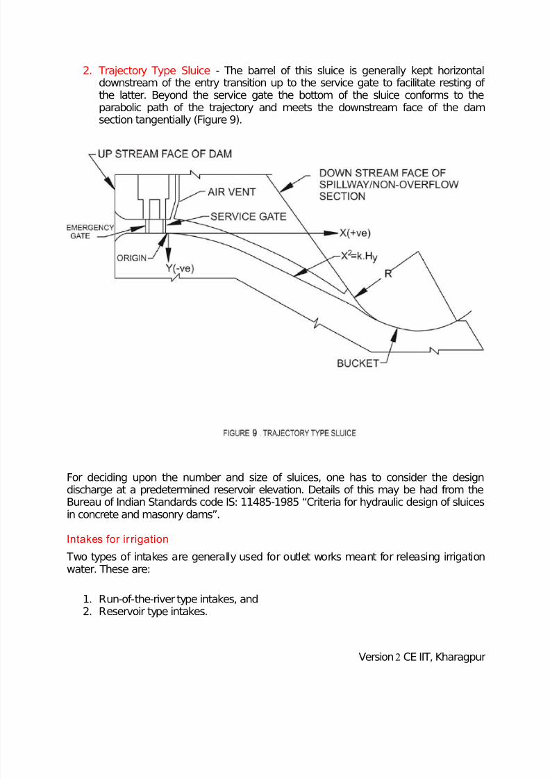
2. Trajectory Type Sluice - The barrel of this sluice is generally kept horizontaldownstream of the entry transition up to the service gate to facilitate resting of the latter. Beyond the service gate the bottom of the sluice conforms to theparabolic path of the trajectory and meets the downstream face of the damsection tangentially (Figure 9).
For deciding upon the number and size of sluices, one has to consider the designdischarge at a predetermined reservoir elevation. Details of this may be had from theBureau of Indian Standards code IS: 11485-1985 “Criteria for hydraulic design of sluicesin concrete and masonry dams”.
Intakes for ir rigation
Two types of intakes are generally used for outlet works meant for releasing irrigationwater. These are:
1. Run-of-the-river type intakes, and2. Reservoir type intakes.
Version2 CE IIT, Kharagpur
7/29/2019 Tunnel intake
http://slidepdf.com/reader/full/tunnel-intake 20/25
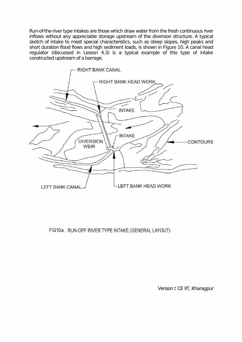
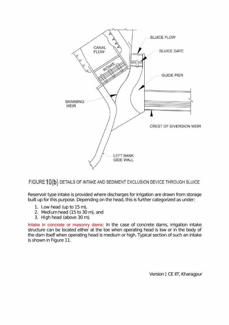
Run-of-the-river type intakes are those which draw water from the fresh continuous riverinflows without any appreciable storage upstream of the diversion structure. A typicalsketch of intake to meet special characteristics, such as steep slopes, high peaks andshort duration flood flows and high sediment loads, is shown in Figure 10. A canal headregulator (discussed in Lesson 4.3) is a typical example of this type of intake
constructed upstream of a barrage.
Version2 CE IIT, Kharagpur
7/29/2019 Tunnel intake
http://slidepdf.com/reader/full/tunnel-intake 21/25
Reservoir type intake is provided where discharges for irrigation are drawn from storagebuilt up for this purpose. Depending on the head, this is further categorized as under:
1. Low head (up to 15 m),2. Medium head (15 to 30 m), and3. High head (above 30 m).
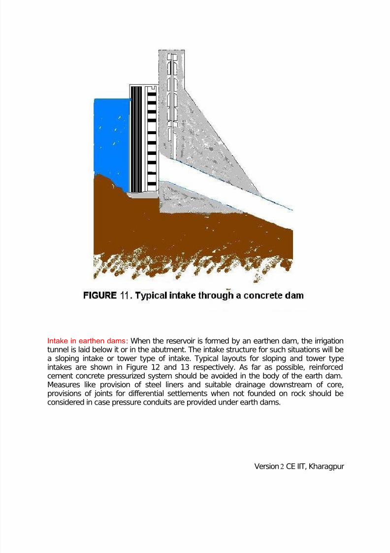
Intake in concrete or masonry dams: In the case of concrete dams, irrigation intakestructure can be located either at the toe when operating head is low or in the body of the dam itself when operating head is medium or high. Typical section of such an intakeis shown in Figure 11.
Version2 CE IIT, Kharagpur
7/29/2019 Tunnel intake
http://slidepdf.com/reader/full/tunnel-intake 22/25
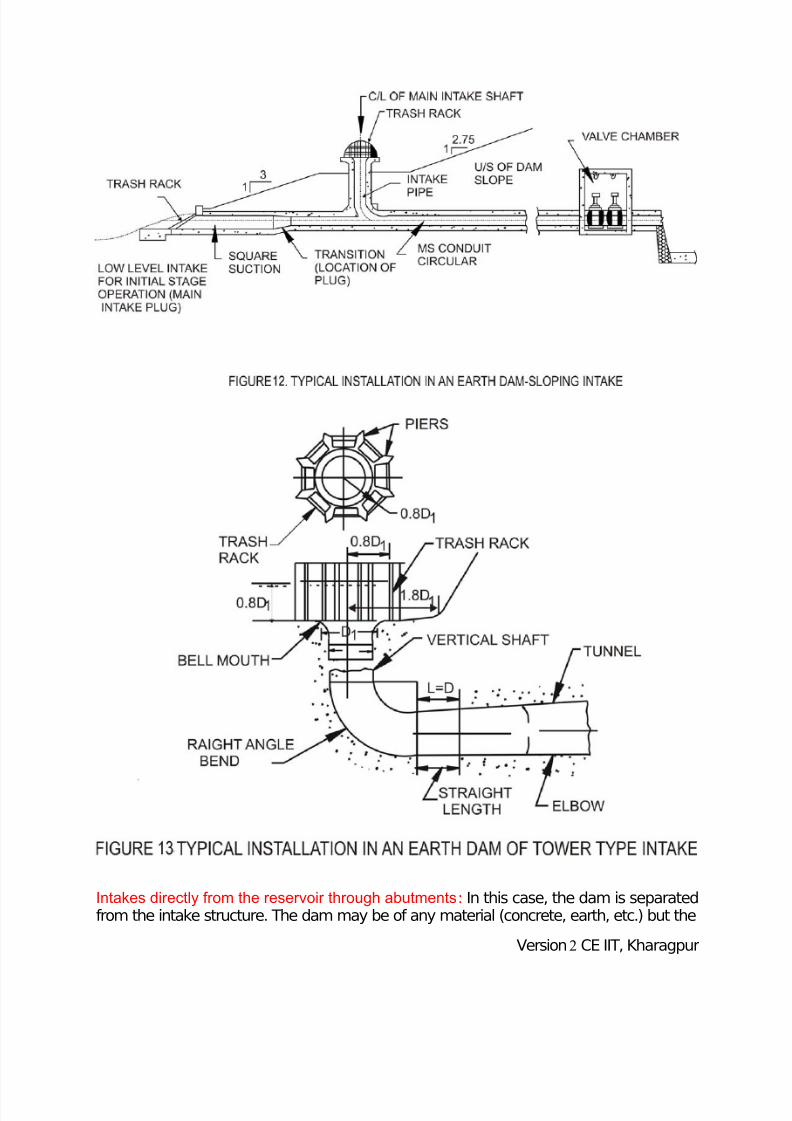
Intake in earthen dams: When the reservoir is formed by an earthen dam, the irrigationtunnel is laid below it or in the abutment. The intake structure for such situations will bea sloping intake or tower type of intake. Typical layouts for sloping and tower typeintakes are shown in Figure 12 and 13 respectively. As far as possible, reinforcedcement concrete pressurized system should be avoided in the body of the earth dam.
Measures like provision of steel liners and suitable drainage downstream of core,provisions of joints for differential settlements when not founded on rock should beconsidered in case pressure conduits are provided under earth dams.
Version2 CE IIT, Kharagpur
7/29/2019 Tunnel intake
http://slidepdf.com/reader/full/tunnel-intake 23/25
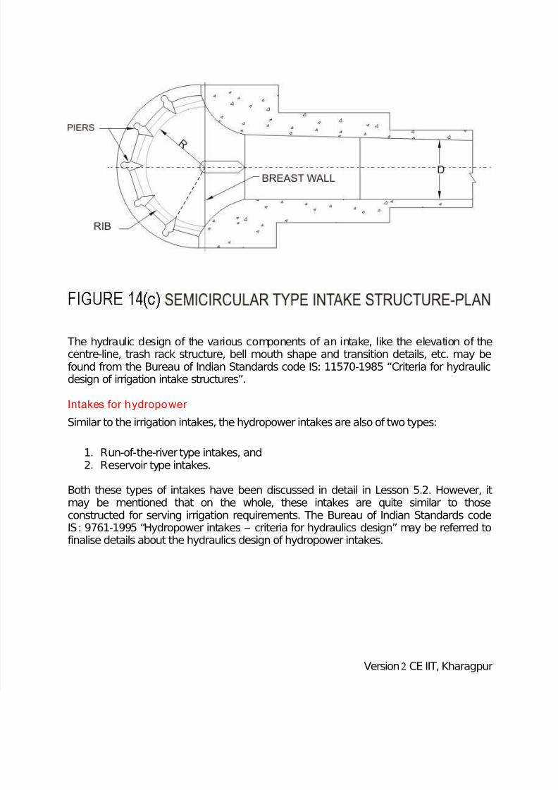
Intakes directly from the reservoir through abutments: In this case, the dam is separatedfrom the intake structure. The dam may be of any material (concrete, earth, etc.) but the
Version2 CE IIT, Kharagpur

7/29/2019 Tunnel intake
http://slidepdf.com/reader/full/tunnel-intake 24/25
intake is constructed by grading the left or right abutments and leading the outlet pipesthrough the surrounding hills. Figures 14 (a) through (c) show the typical layout, sectionand plan of such an intake.
Version2 CE IIT, Kharagpur
7/29/2019 Tunnel intake
http://slidepdf.com/reader/full/tunnel-intake 25/25
The hydraulic design of the various components of an intake, like the elevation of thecentre-line, trash rack structure, bell mouth shape and transition details, etc. may befound from the Bureau of Indian Standards code IS: 11570-1985 “Criteria for hydraulicdesign of irrigation intake structures”.
Intakes for hydropower
Similar to the irrigation intakes, the hydropower intakes are also of two types:
1. Run-of-the-river type intakes, and2. Reservoir type intakes.
Both these types of intakes have been discussed in detail in Lesson 5.2. However, itmay be mentioned that on the whole, these intakes are quite similar to thoseconstructed for serving irrigation requirements. The Bureau of Indian Standards codeIS: 9761-1995 “Hydropower intakes – criteria for hydraulics design” may be referred tofinalise details about the hydraulics design of hydropower intakes.
Version2 CE IIT Kharagpur