Embed Size (px)
Citation preview
TUNNEL SUPPORTS
CIRCULAR TUNNEL(IN CONTINUATION OF TUNNEL IN WEAK ROCK)
1
Created By:
Shaloo Puri
Website: www.geotechnicaldesigns.com.au
Email id : [email protected]
WhatsApp: +61452075310
BASIC CONCEPT
This presentation is based on paper by Hoek : Tunnels in weak
rocks
Based on basic concepts:
❖ The process of designing of support system.
❖ How rock mass surrounding tunnel deforms
❖ How support system acts to control this
deformation.
www.geotechnicaldesigns.com.au
2
www.geotechnicaldesigns.com.au
3
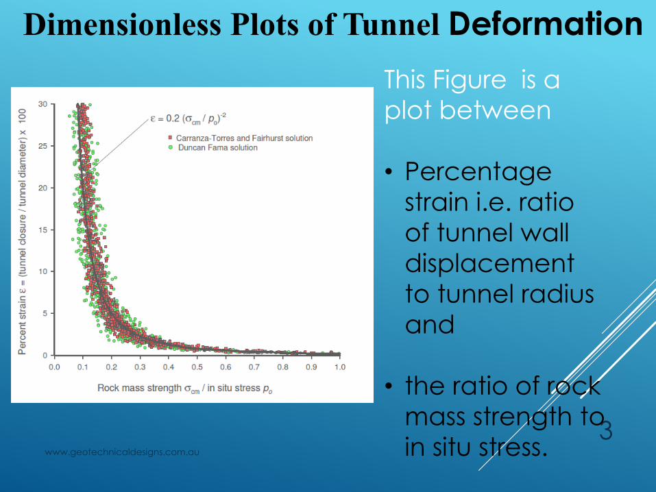
Dimensionless Plots of Tunnel Deformation
This Figure is a
plot between
• Percentage
strain i.e. ratio
of tunnel wall
displacement
to tunnel radius
and
• the ratio of rock
mass strength to
in situ stress.
www.geotechnicaldesigns.com.au
4
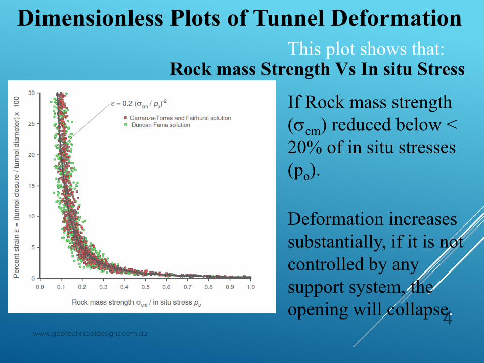
Dimensionless Plots of Tunnel Deformation
This plot shows that:
If Rock mass strength
(cm) reduced below <
20% of in situ stresses
(po).
Deformation increases
substantially, if it is not
controlled by any
support system, the
opening will collapse.
Rock mass Strength Vs In situ Stress
www.geotechnicaldesigns.com.au
5
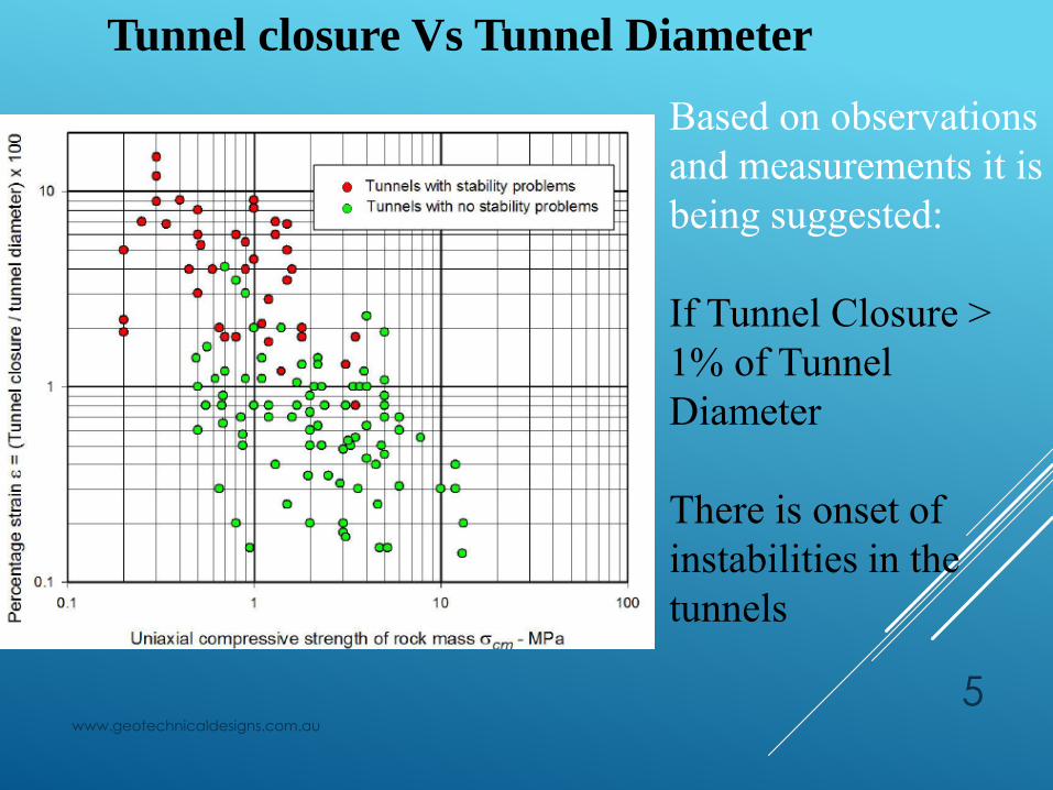
Based on observations
and measurements it is
being suggested:
If Tunnel Closure >
1% of Tunnel
Diameter
There is onset of
instabilities in the
tunnels
Tunnel closure Vs Tunnel Diameter
www.geotechnicaldesigns.com.au 6
Therefore from the above two conditions the conclusion
is the following
➢ If Rock mass strength (cm) reduced below < 20%
of in situ stresses (po).
➢ Tunnel Closure > 1% of Tunnel Diameter
Deformation increases substantially, if it is not controlled
by any support system, the opening will collapse
www.geotechnicaldesigns.com.au
7
Tunnel Displacement for Different
Support Pressures
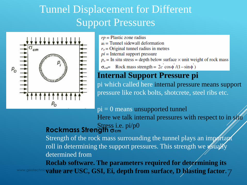
Internal Support Pressure pipi which called here internal pressure means support
pressure like rock bolts, shotcrete, steel ribs etc.
pi = 0 means unsupported tunnel
Here we talk internal pressures with respect to in situ
Stress i.e. pi/p0Rockmass Strength cm
Strength of the rock mass surrounding the tunnel plays an important
roll in determining the support pressures. This strength we usually
determined from
Roclab software. The parameters required for determining its
value are USC, GSI, Ei, depth from surface, D blasting factor.
www.geotechnicaldesigns.com.au
8
Tunnel Displacement for Different
Support Pressures
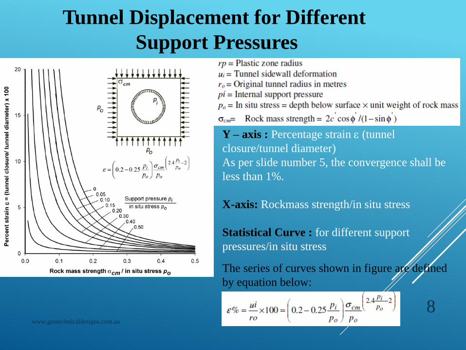
Y – axis : Percentage strain (tunnel
closure/tunnel diameter)
As per slide number 5, the convergence shall be
less than 1%.
X-axis: Rockmass strength/in situ stress
Statistical Curve : for different support
pressures/in situ stress
The series of curves shown in figure are defined
by equation below:
www.geotechnicaldesigns.com.au
9
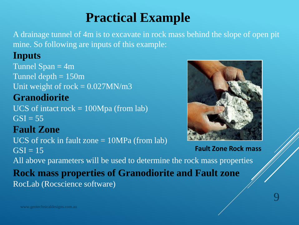
Practical Example
InputsTunnel Span = 4m
Tunnel depth = 150m
Unit weight of rock = 0.027MN/m3
GranodioriteUCS of intact rock = 100Mpa (from lab)
GSI = 55
Fault ZoneUCS of rock in fault zone = 10MPa (from lab)
GSI = 15
All above parameters will be used to determine the rock mass properties
A drainage tunnel of 4m is to excavate in rock mass behind the slope of open pit
mine. So following are inputs of this example:
Rock mass properties of Granodiorite and Fault zoneRocLab (Rocscience software)
www.geotechnicaldesigns.com.au
10
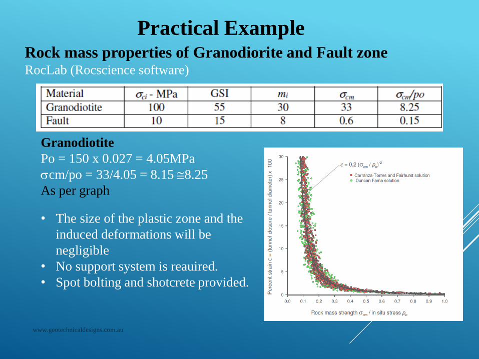
Practical ExampleRock mass properties of Granodiorite and Fault zoneRocLab (Rocscience software)
Granodiotite
Po = 150 x 0.027 = 4.05MPa
cm/po = 33/4.05 = 8.15 8.25
As per graph
• The size of the plastic zone and the
induced deformations will be
negligible
• No support system is reauired.
• Spot bolting and shotcrete provided.
www.geotechnicaldesigns.com.au
11
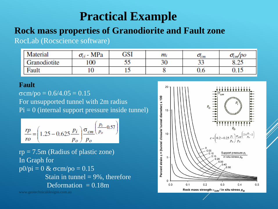
Practical ExampleRock mass properties of Granodiorite and Fault zoneRocLab (Rocscience software)
Fault
cm/po = 0.6/4.05 = 0.15
For unsupported tunnel with 2m radius
Pi = 0 (internal support pressure inside tunnel)
rp = 7.5m (Radius of plastic zone)
In Graph for
p0/pi = 0 & cm/po = 0.15
Stain in tunnel = 9%, therefore
Deformation = 0.18m
www.geotechnicaldesigns.com.au
12
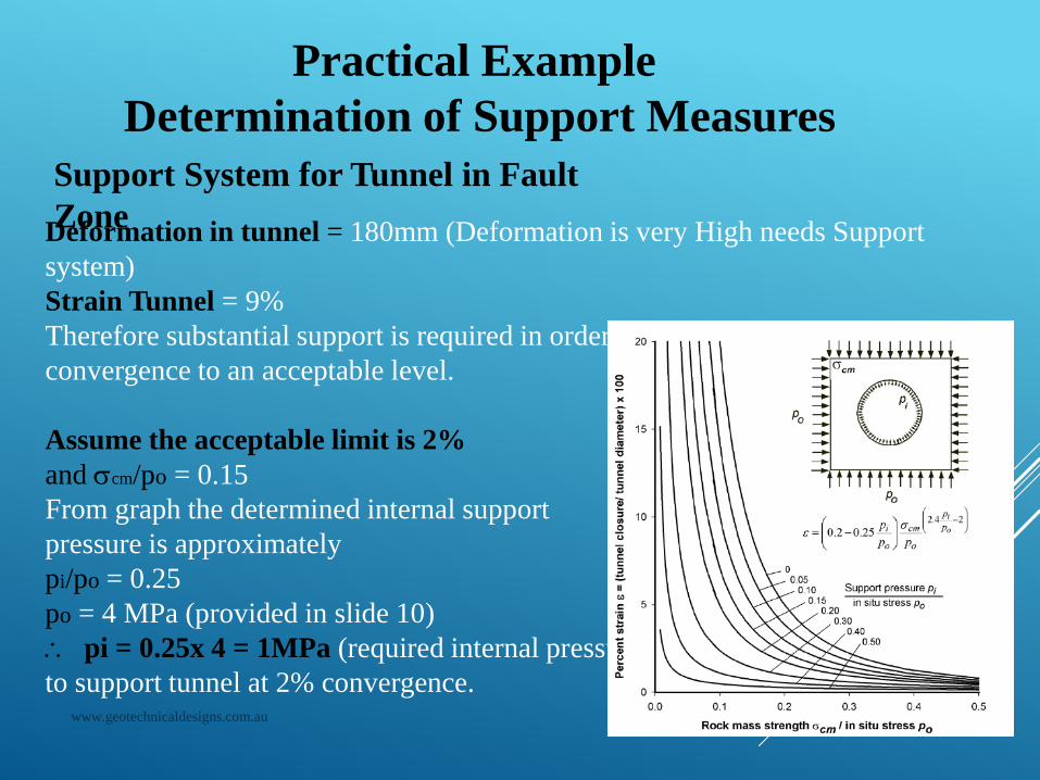
Practical Example
Determination of Support Measures
Support System for Tunnel in Fault
ZoneDeformation in tunnel = 180mm (Deformation is very High needs Support
system)
Strain Tunnel = 9%
Therefore substantial support is required in order to prevent collapse and
convergence to an acceptable level.
Assume the acceptable limit is 2%
and cm/po = 0.15
From graph the determined internal support
pressure is approximately
pi/po = 0.25
po = 4 MPa (provided in slide 10)
pi = 0.25x 4 = 1MPa (required internal pressure
to support tunnel at 2% convergence.
www.geotechnicaldesigns.com.au
13
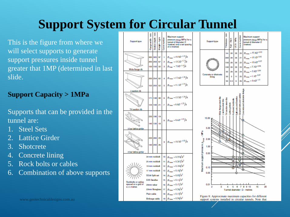
Support System for Circular Tunnel
This is the figure from where we
will select supports to generate
support pressures inside tunnel
greater that 1MP (determined in last
slide.
Support Capacity > 1MPa
Supports that can be provided in the
tunnel are:
1. Steel Sets
2. Lattice Girder
3. Shotcrete
4. Concrete lining
5. Rock bolts or cables
6. Combination of above supports
www.geotechnicaldesigns.com.au
14
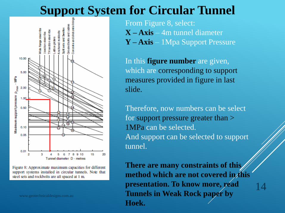
Support System for Circular TunnelFrom Figure 8, select:
X –Axis – 4m tunnel diameter
Y –Axis – 1Mpa Support Pressure
In this figure number are given,
which are corresponding to support
measures provided in figure in last
slide.
Therefore, now numbers can be select
for support pressure greater than >
1MPa can be selected.
And support can be selected to support
tunnel.
There are many constraints of this
method which are not covered in this
presentation. To know more, read
Tunnels in Weak Rock paper by
Hoek.
www.geotechnicaldesigns.com.au
15
Support System for Circular TunnelThe required internal support pressure is 1MPa. Therefore the provided
shall be more than 1Mpa.
In graph in slide 14, there are curve numbers 1 to 26 which represents
type of support like steel ribs, lattice girder, shotcrete, concrete lining, rock
bolts which are presented in figure provide slide no 13.
From figure 8 in slide 13, you can decide the type of support you need to
provide to support the tunnel.
Support system depends upon the rock class tunnel is going through like in
Good Rock – Spot Bolting & Shotcrete
Fair Rock – Pattern Bolting & Shotcrete
Poor Rock – Pattern Bolting & Shotcrete
Very Poor to Extremely Poor – Steel Ribs and Shotcrete
Here Tunnel is passing through fault zone so the it is very poor to
extremely poor rock. Therefore the support system should be steel ribs .
www.geotechnicaldesigns.com.au
16
Support System for Circular Tunnel
From Slide 14, we will select no. 3 curve number as it is providing
internal support pressure more than required support pressure of
1Mpa .
Curve No. 3
Maximum Support pimax = 7.0 D-1.4/s = 7.0 x 4-1.4/1
= 4.9 MPa is the provided pressure by Steel Ribs spaced at 1m
distance.
www.geotechnicaldesigns.com.au
17
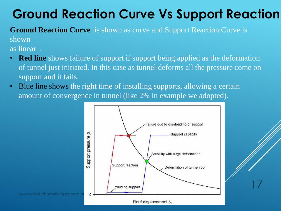
Ground Reaction Curve Vs Support Reaction Curve Ground Reaction Curve is shown as curve and Support Reaction Curve is
shown
as linear .
• Red line shows failure of support if support being applied as the deformation
of tunnel just initiated. In this case as tunnel deforms all the pressure come on
support and it fails.
• Blue line shows the right time of installing supports, allowing a certain
amount of convergence in tunnel (like 2% in example we adopted).

www.geotechnicaldesigns.com.au
18
❖ If you find my presentation useful, please provide your
comments
and also provide your valuable advice that how can I improve my
presentation.
❖ Also share your topic or paper or an article you want me to
present in short and in concise way.
❖ If you want to know more about our services. Please follow our
Website:
www.geotechnicaldesigns.com.au

www.geotechnicaldesigns.com.au
19
THANK YOU
FOR
YOUR PRECIOUS TIME