Embed Size (px)
Citation preview
TUNNEL-ANGUSS-EINSÄTZE
Vers
. 5
tunnel gate insertsinserti d‘iniezione a tunnel
2 www.i-mold.com
Molding Innovations made by i-mold.
EN
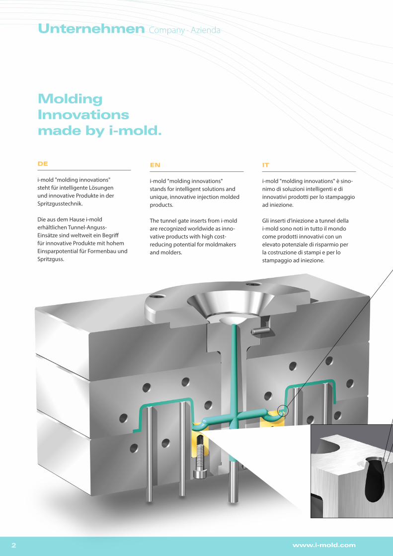
i-mold "molding innovations" stands for intelligent solutions and unique, innovative injection molded products.
The tunnel gate inserts from i-mold are recognized worldwide as inno-vative products with high cost-reducing potential for moldmakers and molders.
DE
i-mold "molding innovations" steht für intelligente Lösungen und innovative Produkte in der Spritzgusstechnik.
Die aus dem Hause i-mold erhältlichen Tunnel-Anguss-Einsätze sind weltweit ein Begriff für innovative Produkte mit hohem Einsparpotential für Formenbau und Spritzguss.
IT
i-mold "molding innovations" è sino-nimo di soluzioni intelligenti e di innovativi prodotti per lo stampaggio ad iniezione.
Gli inserti d’iniezione a tunnel della i-mold sono noti in tutto il mondo come prodotti innovativi con un elevato potenziale di risparmio per la costruzione di stampi e per lo stampaggio ad iniezione.
Unternehmen Company · Azienda

3www.i-mold.com
DE
>Zeit- und Kostenersparnis durch einfache Verwendung
> Hoch verschleißfester Warm- arbeitsstahl M2 (1.3343)
> Hohe Prozesssicherheit bei der Produktion
> Verdeckte Angussmarkierung durch unterseitige Anspritzung
> Einteilige Bauform ermöglicht kompakte Abmessungen
> Viele verschiedene Varianten und unterschiedliche Größen erhältlich
> Exakte Angusstrennung durch integrierte Abrisskante
> Durch optimierte Kanalgeometrie für alle Kunststoffe geeignet – Füllstoffanteile (z. B. GF) bis zu 60% möglich
> Glatte Angusskanäle und exakte Anschnittgrößen durch MIM- Verfahren
EN
> Time and cost reduction thanks to fast and easy application
> Made of highly wear-resistant hot work tool steel M2 (1.3343)
> High degree of reliability in production process
> Invisible gate marks through underside gating
> Single-part design for compact dimensions
> Available in many different versions and sizes
> Integrated cutting edge for exact sprue separation
> Suitable for all plastics thanks to optimized feed channel geometry – up to 60% filler content (e.g. glass fibre) is possible
> Use of MIM process ensures smooth feed channels and exact gate sizes
Warum Anguss-Einsätze? Why gate inserts?Perché inserti d’iniezione?
IT
> Risparmio di tempo e costi grazie al facile impiego
> Elevata resistenza all’usura grazie al materiale sinterizzato M2 (1.3343)
> Elevata affidabilità dei processi di produzione
> Tracce d’iniezione invisibili grazie all’iniezione dal lato inferiore
> La forma monoblocco consente dimensioni compatte
> Disponibile in numerose differenti versioni e dimensioni
> Esatta separazione della materozza grazie al bordo di distacco integrato.
> Adatto per tutte le materie plastiche, grazie alla geometria dei canali ottimizzata – consente percentuali di riempitivo (p. es. GF) fino al 60%
> Canali d’iniezione lisci ed esatte dimensioni dei punti d’iniezione grazie al processo MIM
DE_Auf unserer Website halten wir für unsere Kunden sämtliche benötigten 3D-CAD-Daten zum Download bereit.
EN_Visit our website www.i-mold.com for complete 3D-CAD data.
IT_I dati 3D-CAD completi sono disponibili presso la nostra website www.i-mold.com.
www.i-mold.de

4 www.i-mold.com
StandardVersion S2
StandardVersion S1
KonturierbarContourableContornabile
HaltebuchseRetaining bushBoccola di arresto
ProduktübersichtProduct overview · Panoramica prodotti
Seitliche AnspritzungSide gatingIniezione laterale
Seitliche AnspritzungSide gatingIniezione laterale
KonturierbarContourableContornabile

5www.i-mold.com
PRODUKTDETAILS Product details · Dettagli prodotto
EINBAUANLEITUNG Installation instructions · Istruzioni per il montaggio
EINBAUBEISPIELE Examples of installation · Esempi di montaggio
PRODUKTDETAILS Product details · Dettagli prodotto
EINBAUANLEITUNG Installation instructions · Istruzioni per il montaggio
EINBAUBEISPIELE Examples of installation · Esempi di montaggio
PRODUKTDETAILS Product details · Dettagli prodotto
EINBAUANLEITUNG Installation instructions · Istruzioni per il montaggio
EINBAUBEISPIELE Examples of installation · Esempi di montaggio
PRODUKTDETAILS Product details · Dettagli prodotto
EINBAUANLEITUNG Installation instructions · Istruzioni per il montaggio
EINBAUBEISPIELE Examples of installation · Esempi di montaggio
PRODUKTDETAILS Product details · Dettagli prodotto
EINBAUANLEITUNG Installation instructions · Istruzioni per il montaggio
EINBAUBEISPIELE Examples of installation · Esempi di montaggio
PRODUKTDETAILS Product details · Dettagli prodotto
EINBAUANLEITUNG Installation instructions · Istruzioni per il montaggio
EINBAUBEISPIELE Examples of installation · Esempi di montaggio
PRODUKTDETAILS Product details · Dettagli prodotto
ProduktübersichtProduct overview · Panoramica prodotti
TGR TGS
TGR TGS
TGC
SGC
TPS
S2
S2
S1
ERGÄNZENDE TIPPS Supplementary tips · Consigli supplementari
TGLLTGML TGHL
7-8
9
10
11-12
13
14
15-16
37
17
21-23
37
24
25-26
27
28
29-30
31
32
33
34-39

6 www.i-mold.com
Anschnittdurchmesser · Gate Diameter · Diametro del punto d’iniezione
ØQuerschnittsfläche
in mm2
Cross-sectional area mm²Superficie trasversale mm²
TGS/TGR TGC-XS SGC-XS
TGC-SSGC-STPS-S
TGC-1 SGC-1TPS-1
TGLL-1TGML-1TGHL-1
TGC-2SGC-2TPS-2
TGLL-2TGML-2TGHL-2
TGC-3 / -4SGC-3 / -4
TPS-3TGLL-3TGML-3TGHL-3
0,4 0,6 0,8 1,0 1,2 1,4 1,6 1,8 2,0 2,2 2,4 2,6 2,8 3,0 3,2
:4,5
0,13 0,28 0,50 0,78 1,13 1,54 2,01 2,54 3,14 3,8
4,52 5,31 6,15 7,07 8,04
:18,8
Technische InformationTechnical information · Informazioni tecniche
Anschnitt
Gate
Punto d’iniezione
3,2
3,0
2,8
2,6
2,4
2,2
2,0
1,8
1,6
1,4
1,2
1,0
0,8
0,6
0,4
0,2
0,5 1 2 3 4 5 7 9 12 15 20 25 30 35 40 45 50 60 70 80 90 100 150 200 300 400 500 600 800 1000
Schussgewicht (g) · Shotweight (g) · Peso d‘iniezione (g)
HV MV NVViskositätsdiagramm · Viscosity graph · Diagramma di viscosità
NV = niedrige Viskosität / low viscosity / bassa viscosità
MV = mittlere Viskosität / medium viscosity / media viscosità
HV = hohe Viskosität / high viscosity / elevata viscosità
Ø
Beispiel für 25 g PC · Example for 25 g PC · Esempi per 25 g PC
1,4
0,4
0,6
0,8
1,0
1,2
0,60,8 1,0 1,21,4
1,8
0,6
0,8
1,2
1,6
2,0
2,4
2,8
0,8 1,0 1,2 1,4 1,6 1,8
2,1
2,8
0,40,60,8
TGR / TGS / TGC / TGLL / TGML / TGHL
0,5 x (4,5)0,6 x (4,6)0,7 x (4,7)0,8 x (4,8)0,9 x (4,9)1,0 x (5,0)1,1 x (5,1)1,2 x (5,2)1,3 x (5,3)1,4 x (5,4)1,5 x (5,5)
4,5
SGC TPS
EN
Caution: When using filled plastics (glass fibres, carbon fibres etc.) you should increase the com-puted gate diameter by 20%.
The recommended shotweights and gate diameters are guide values only! Please also take into account such individual parameters as part geometry, mold design, type of plastic and fillers.
IT
Attenzione: In caso di impiego di plastica caricata (fibre di vetro, di carbonio ecc.) è necessario aumen-tare del 20% il diametro d’iniezione calcolato in base alla tabella!
I pesi ed i diametri d’iniezione consigliati sono soltanto valori indicativi. La geometria del pezzo, il sistema di stampo, il tipo di plastica ed i riempitivi devono essere considerati individualmente.
DE
Achtung: Bei Verwendung von gefüllten Kunst- stoffen (Glasfaser, Kohlefaser, etc.), den mit der Tabelle ermittelten Anschnittdurchmesser um 20 % vergrößern!
Die empfohlenen Schussgewichte und Anschnitt-durchmesser sind nur Richtwerte. Geometrie des Teiles, Werkzeugkonzept, Kunststofftyp und Füll-stoffe müssen individuell berücksichtigt werden.

7www.i-mold.com
Technische InformationTechnical information · Informazioni tecniche
S2
TGR TGSS2mit Kalotte
with vestigecon calotta
TGS TGR
TGR 6 TGR/TGS 8 TGR/TGS 10 TGR/TGS 12 TGR/TGS 14
Anschnitt / gate point / punto d’iniezione 0.6 0,6 / 0,8 0,8 / 1,2 / 1,6 1,2 / 1,6 / 2,0 1,6 / 2,0 / 2,4 / 2,8
Ø Kanal / runner / canale 2.5 3 4 5 6
max. Schussgewichte (g) · max. shotweight (g) · pesi d‘iniezione max. (g)
NV 3 5 30 50 200
MV 2 4 20 35 120
HV 1 3 12 25 75
NV = niedrige Viskosität / low viscosity / bassa viscositàMV = mittlere Viskosität / medium viscosity / media viscositàHV = hohe Viskosität / high viscosity / elevata viscosità
DE > für flache Trennungen, inkl. Kalotte mit integrierter Abrisskante > direkt einsetzbar! Keine Anpassungen erforderlich > in Härte 60 HRC erhältlich > erhältlich in runder (TGR) und eckiger (TGS) Ausführung
EN > for flat parting surfaces, including vestige with integrated cutting edge > ready to use! No adjustments necessary > available with hardness 60 HRC > available in round (TGR) and square (TGS) versions
IT > per separazioni piatte, inclusa calotta con bordo di distacco integrato > impiego diretto! Non sono necessari adattamenti > disponibile in durezze 60 HRC > disponibile in versione tonda (TGR) e squadrata (TGS)
TG
R / T
GS
S2
Geeignet für alle Kunststoffe · Suitable for all plastics · Adatto per ogni tipo di plastica

8 www.i-mold.com
TGS Typ b b1 d1 d2 d3 h h1 h2 l1 l2 M Version
TGS8 8 6 0.6 1.9 3 22.0 0.6 1.1 13 3.25 4 S20.8 2.1
TGS10 10 8 0.8 2.2 4 22.0 0.8 1.2 12 4 5 S21.2 2.61.6 3.0
TGS12 12 10 1.2 2.6 5 22.0 0.8 1.40 11 5 5 S21.6 3.02.0 3.4
TGS14 14 12 1.6 3.0 6 22.0 0.8 1.6 10 6 6 S22.0 3.42.4 3.82.8 4.2
TGR Typ d d1 d2 d3 h h1 h2 l1 l2 M Version
TGR6 6 0.6 1.9 2.5 17.0 0.6 0.8 10 2.5 4 S2TGR8 8 0.6 1.9 3 22.0 0.6 1.1 13 3.25 4
0.8 2.1TGR10 10 0.8 2.2 4 22.0 0.8 1.2 12 4 5 S2
1.2 2.61.6 3.0
TGR12 12 1.2 2.6 5 22.0 0.8 1.4 11 5 5 S21.6 3.02.0 3.4
TGR14 14 1.6 3.0 6 22.0 0.8 1.6 10 6 6 S22.0 3.42.4 3.82.8 4.2
TGR | TGS mit Kalotte with vestige · con calotta
Ø d1
Ø d2
h
Ød
3/2
I1
h2
M35°
15°
h1
R0.25
b
b1
Ø d3
l2
Ø d
Ø d3
l2
0.3
+0.
015
0
-0.0150
0 -0.0
15
-0.0150
Y X
Ød1
Ød2
h
Ød3
/2I1
h2
M35°
15°
h1
R 0.25
b
b1
Ød3
l2
Ød
Ød3
l2
0.3
+0.
015
0
-0.0150
0 -0.0
15
-0.0150
Y X
Beispiel Bestellbezeichnung · Example of order specification · Esempio codice di ordinazione: TGR6-06-S2
S2
Ø 10 0-0.015
M5
CAD
CAD
22+
0.01
5 0
Ø 4
35∞
15∞
0.8 R 0.25
1.2
Øb
4
ØaCAD
0.3
12
4
0.8
Y X
XY
Mögliche VerdrehsicherungAnti-rotation locking possibilityPossibilità di protezione antitorsioneØd1
Ød2
h
Ød3
/2I1
h2
M35°
15°
h1
R 0.25
b
b1
Ød3
l2
Ød
Ød3
l2
0.3
+0.
015
0
-0.0150
0 -0.0
15
-0.0150
Y X
Ød1
Ød2
h
Ød3
/2I1
h2
M35°
15°
h1R 0.25
b
b1
Ød3
l2
Ød
Ød3
l2
0.3
+0.
015
0
-0.0150
0 -0.0
15
-0.0150
Y X
Ød1
Ød2
h
Ød3
/2I1
h2
M35°
15°
h1
R 0.25
b
b1
Ød3
l2
Ød
Ød3
l2
0.3
+0.
015
0
-0.0150
0 -0.0
15
-0.0150
Y X
Ød1
Ød2
h
Ød3
/2I1
h2
M35°
15°
h1
R 0.25
b
b1
Ød3
l2
Ød
Ød3
l2
0.3
+0.
015
0
-0.0150
0 -0.0
15
-0.0150
Y X
X
Y
9www.i-mold.com
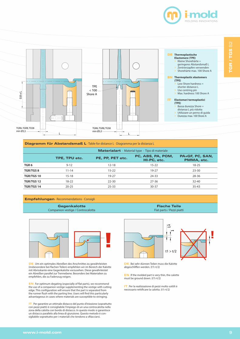
Empfehlungen · Recommendations · Consigli
Gegenkalotte Companion vestige / Controcalotta
Flache Teile Flat parts / Pezzi piatti
L
TGR6, TGR8, TGS8min Ø3,5
0.8
x L
Diagramm für Abstandsmaß L · Table for distance L · Diagramma per la distanza L
Materialart · Material type · Tipo di materiale
TPE, TPU etc. PE, PP, PET etc.PC, ABS, PA, POM,
HI-PC, etc.PA+GF, PC, SAN,
PMMA, etc.
TGR 6 9-12 12-18 15-22 18-25
TGR/TGS 8 11-14 15-22 19-27 23-30
TGR/TGS 10 15-18 19-27 24-33 28-36
TGR/TGS 12 18-22 22-30 27-36 32-40
TGR/TGS 14 20-25 25-33 30-37 35-43
S2 Gegenkalotte !
t1t
S2 Flache Teile
t1 > t/2
DE_Um ein optimales Abreißen des Anschnittes zu gewährleisten(insbesondere bei flachen Teilen) empfehlen wir im Bereich der Kalottemit Abrisskante eine Gegenkalotte vorzusehen. Diese gewährleistetein Abreißen parallel zur Trennebene. Besonders bei Materialien zuempfehlen, die zu Fadenzug neigen.
EN_For optimum degating (especially of flat parts), we recommend the use of a companion vestige supplementing the vestige with cutting edge. This configuration will ensure that the part is separated from the runner flush with the parting line. Users will find this particularly advantageous in cases where materials are susceptible to stringing.
IT_Per garantire un ottimale distacco del punto d’iniezione (soprattutto con pezzi piatti) è consigliabile l’impiego di un una controcalotta nella zona della calotta con bordo di distacco. In questo modo si garantisce un distacco parallelo alla linea di giunzione. Questo metodo è con-sigliabile soprattutto per i materiali che tendono a sfilacciarsi.
DE_Bei sehr dünnen Teilen muss die Kalotte abgeschliffen werden. (t1>t/2)
EN_If the molded part is very thin, the calotte must be ground down. (t1>t/2)
IT_Per la realizzazione di pezzi molto sottili è necessario rettificare la calotta. (t1>t/2)
S2 Gegenkalotte !!
t1t
S2 Flache Teile
t1 > t/2
!
L
TGR6, TGR8, TGS8min Ø3,5
TPE< 100
Shore A
DE Thermoplastische Elastomere (TPE) > Kleine Shorehärte = geringeres Abstandsmaß L > Zentrierzapfen verwenden > Shorehärte max. 100 Shore A
EN Thermoplastic elastomers (TPE) > Low Shore hardness = shorter distance L > Use centring pin > Max. hardness 100 Shore A
IT Elastomeri termoplastici (TPE) > Bassa durezza Shore = distanza L più ridotta > Utilizzare un perno di guida > Durezza: max. 100 Shore A
TG
R / T
GS
S2
10 www.i-mold.com
Beispiel S2-1
Beispiel S2-2
Beispiel S2-3Beispiel S2-4
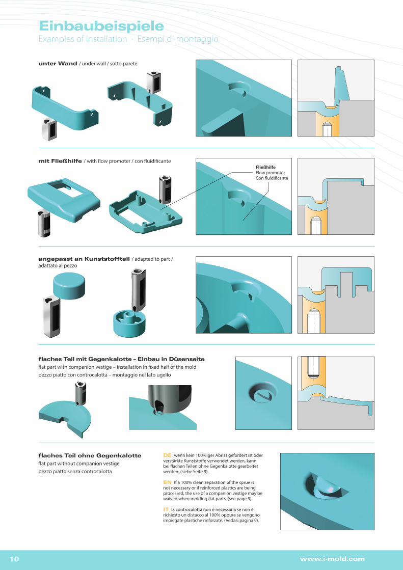
unter Wand / under wall / sotto parete
mit Fließhilfe / with flow promoter / con fluidificante
angepasst an Kunststoffteil / adapted to part / adattato al pezzo
flaches Teil mit Gegenkalotte – Einbau in Düsenseite
flat part with companion vestige – installation in fixed half of the moldpezzo piatto con controcalotta – montaggio nel lato ugello
flaches Teil ohne Gegenkalotte
flat part without companion vestigepezzo piatto senza controcalotta
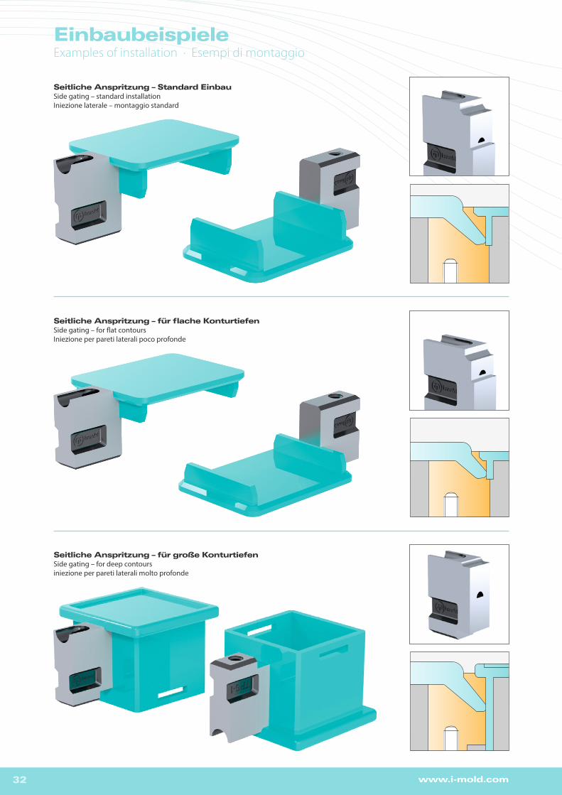
DE_wenn kein 100%iger Abriss gefordert ist oder verstärkte Kunststoffe verwendet werden, kann bei flachen Teilen ohne Gegenkalotte gearbeitet werden. (siehe Seite 9).
EN_If a 100% clean separation of the sprue is not necessary or if reinforced plastics are being processed, the use of a companion vestige may be waived when molding flat parts. (see page 9).
IT_la controcalotta non è necessaria se non è richiesto un distacco al 100% oppure se vengono impiegate plastiche rinforzate. (Vedasi pagina 9).
Fließhilfe Flow promoter Con fluidificante
EinbaubeispieleExamples of installation · Esempi di montaggio
11www.i-mold.com
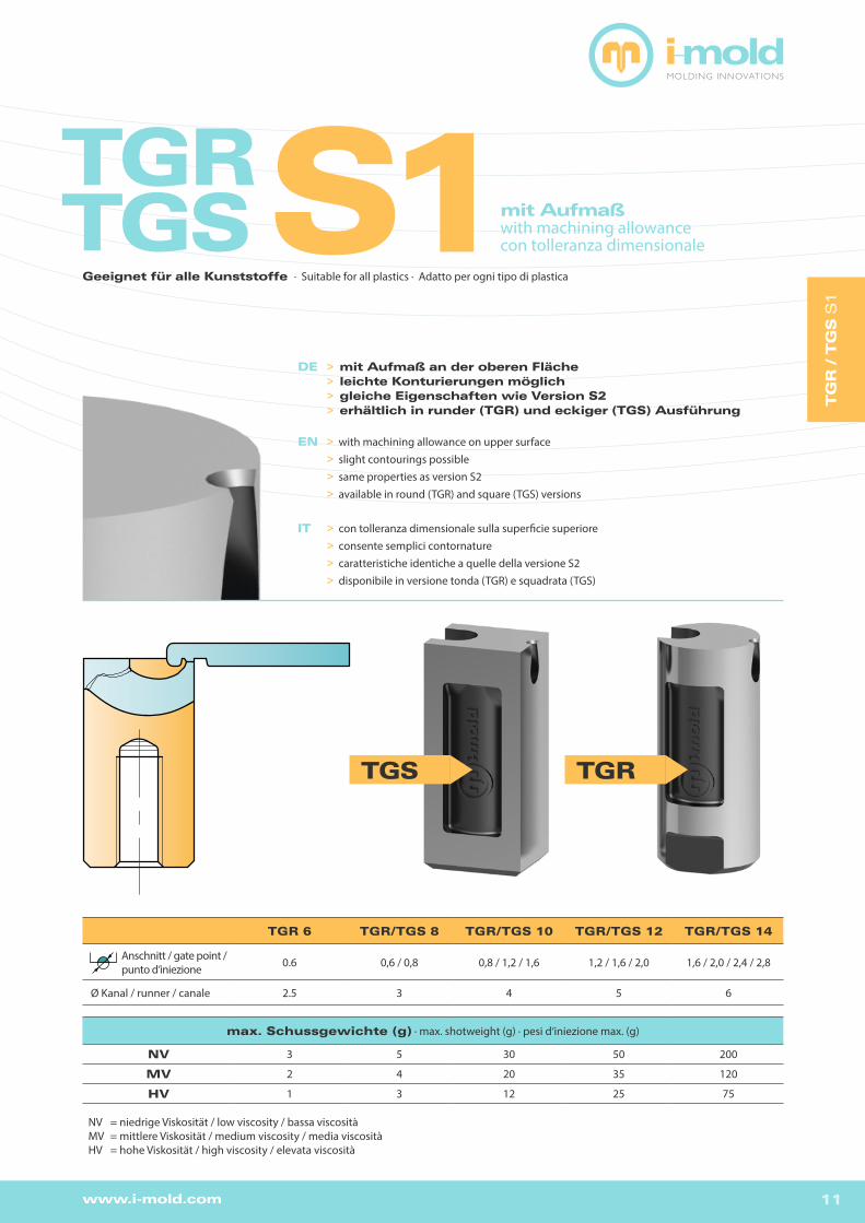
TGR TGSS1mit Aufmaß
with machining allowancecon tolleranza dimensionale
TGS TGR
TGR 6 TGR/TGS 8 TGR/TGS 10 TGR/TGS 12 TGR/TGS 14
Anschnitt / gate point / punto d’iniezione 0.6 0,6 / 0,8 0,8 / 1,2 / 1,6 1,2 / 1,6 / 2,0 1,6 / 2,0 / 2,4 / 2,8
Ø Kanal / runner / canale 2.5 3 4 5 6
max. Schussgewichte (g) · max. shotweight (g) · pesi d‘iniezione max. (g)
NV 3 5 30 50 200
MV 2 4 20 35 120
HV 1 3 12 25 75
NV = niedrige Viskosität / low viscosity / bassa viscositàMV = mittlere Viskosität / medium viscosity / media viscositàHV = hohe Viskosität / high viscosity / elevata viscosità
DE >mit Aufmaß an der oberen Fläche >leichte Konturierungen möglich >gleiche Eigenschaften wie Version S2 >erhältlich in runder (TGR) und eckiger (TGS) Ausführung
EN > with machining allowance on upper surface > slight contourings possible > same properties as version S2 > available in round (TGR) and square (TGS) versions
IT > con tolleranza dimensionale sulla superficie superiore > consente semplici contornature > caratteristiche identiche a quelle della versione S2 > disponibile in versione tonda (TGR) e squadrata (TGS)
TG
R / T
GS
S1
Geeignet für alle Kunststoffe · Suitable for all plastics · Adatto per ogni tipo di plastica
EinbaubeispieleExamples of installation · Esempi di montaggio

12 www.i-mold.com
TGS Typ b b1 d1 d3 h h1 h2 l1 l2 M Version
TGS8 8 6 0.6 3 22.6 0.6 1.7 13 3.25 4 S10.8
TGS10 10 8 0.8 4 22.8 0.8 2.0 12 4 5 S11.21.6
TGS12 12 10 1.2 5 22.8 0.8 2.2 11 5 5 S11.62.0
TGS14 14 12 1.6 6 22.8 0.8 2.4 10 6 6 S12.02.42.8
TGR Typ d d1 d3 h h1 h2 l1 l2 M Version
TGR6 6 0.6 2.5 17.6 0.6 1.4 10 2.5 4 S1TGR8 8 0.6 3 22.6 0.6 1.7 13 3.25 4 S1
0.8TGR10 10 0.8 4 22.8 0.8 2.0 12 4 5 S1
1.21.6
TGR12 12 1.2 5 22.8 0.8 2.2 11 5 5 S11.62.0
TGR14 14 1.6 6 22.8 0.8 2.4 10 6 6 S12.02.42.8
h
h2
I1
M
Ø d1h
135°
b
b1
Ø d3
l2
Ø d
Ø d3
l2
Ød
3/2
0.3
+0.
015
0
0 -0.0
15
0-0.015
0-0.015
Y XBearbeitungsbereichMachining areaAmbito di lavorazione
h
h2
I1
M
Ø d1
h1
35°
b
b1
Ø d3
l2
Ø d
Ø d3
l2
Ød
3/2
0.3
+0.
015
0
0 -0.0
15
0-0.015
0-0.015
Y XBearbeitungsbereichMachining areaAmbito di lavorazione
h
h2
I1
M
Ø d1
h1
35°
b
b1
Ø d3
l2
Ø d
Ø d3
l2
Ød
3/2
0.3
+0.
015
0
0 -0.0
15
0-0.015
0-0.015
Y XBearbeitungsbereichMachining areaAmbito di lavorazione
TGR | TGS mit Aufmaß · with machining allowance · con tolleranza dimensionale S1
h
h2
I1
M
Ø d1
h1
35°
b
b1
Ø d3
l2
Ø d
Ø d3
l2
Ød
3/2
0.3
+0.
015
0
0 -0.0
15
0-0.015
0-0.015
Y XBearbeitungsbereichMachining areaAmbito di lavorazione
X
Y
h
h2
I1
M
Ø d1
h1
35°
b
b1
Ø d3
l2
Ø d
Ø d3
l2
Ød
3/2
0.3
+0.
015
0
0 -0.0
15
0-0.015
0-0.015
Y XBearbeitungsbereichMachining areaAmbito di lavorazione
h
h2
I1
M
Ø d1
h1
35°
b
b1
Ø d3
l2
Ø d
Ø d3
l2
Ød
3/2
0.3
+0.
015
0
0 -0.0
15
0-0.015
0-0.015
Y XBearbeitungsbereichMachining areaAmbito di lavorazione
Mindestgröße der Kalotte wie bei S2Minimum size of vestige same as version S2Dimensioni minime della calotta come per la versione S2
Ø 10 0-0.015
M5
CAD
CAD
22+
0.01
5 0
Ø 4
35∞
15∞
0.8 R 0.25
1.2
Øb
4
ØaCAD
0.3
12
4
0.8
Y X
XY
Mögliche VerdrehsicherungAnti-rotation locking possibilityPossibilità di protezione antitorsione
Beispiel Bestellbezeichnung · Example of order specification · Esempio codice di ordinazione: TGR6-06-S1

13www.i-mold.com
TPE< 100
Shore A
Empfehlungen · Recommendations · Consigli
Gegenkalotte Companion vestige / Controcalotta
Flache Teile Flat parts / Pezzi piatti
DE_Um ein optimales Abreißen des Anschnittes zu gewährleisten(insbesondere bei flachen Teilen) empfehlen wir im Bereich der Kalottemit Abrisskante eine Gegenkalotte vorzusehen. Diese gewährleistetein Abreißen parallel zur Trennebene. Besonders bei Materialien zuempfehlen, die zu Fadenzug neigen.
EN_For optimum degating (especially of flat parts), we recommend the use of a companion vestige supplementing the vestige with cutting edge. This configuration will ensure that the part is separated from the runner flush with the parting line. Users will find this particularly advantageous in cases where materials are susceptible to stringing.
IT_Per garantire un ottimale distacco del punto d’iniezione (soprattutto con pezzi piatti) è consigliabile l’impiego di un una controcalotta nella zona della calotta con bordo di distacco. In questo modo si garantisce un distacco parallelo alla linea di giunzione. Questo metodo è con-sigliabile soprattutto per i materiali che tendono a sfilacciarsi.
DE_Bei sehr dünnen Teilen muss die Kalotte abgeschliffen werden. (t1>t/2)
EN_If the molded part is very thin, the calotte must be ground down. (t1>t/2)
IT_Per la realizzazione di pezzi molto sottili è necessario rettificare la calotta. (t1>t/2)
S1 Gegenkalotte ! !
0.8
x L
S1TGR6, TGR8, TGS8min Ø3,5
LL
TGR6, TGR8, TGS8
min Ø3,5
S1 Gegenkalotte
tt1
S1 Gegenkalotte
t1 > t/2
tt1
S1 Gegenkalotte
t1 > t/2
Diagramm für Abstandsmaß L · Table for distance L · Diagramma per la distanza L
Materialart · Material type · Tipo di materiale
TPE, TPU etc. PE, PP, PET etc.PC, ABS, PA, POM,
HI-PC, etc.PA+GF, PC, SAN,
PMMA etc.
TGR 6 9-12 12-18 15-22 18-25
TGR/TGS 8 11-14 15-22 19-27 23-30
TGR/TGS 10 15-18 19-27 24-33 28-36
TGR/TGS 12 18-22 22-30 27-36 32-40
TGR/TGS 14 20-25 25-33 30-37 35-43
DE Thermoplastische Elastomere (TPE) > Kleine Shorehärte = geringeres Abstandsmaß L > Zentrierzapfen verwenden > Shorehärte max. 100 Shore A
EN Thermoplastic elastomers (TPE) > Low Shore hardness = shorter distance L > Use centring pin > Max. hardness 100 Shore A
IT Elastomeri termoplastici (TPE) > Bassa durezza Shore = distanza L più ridotta > Utilizzare un perno di guida > Durezza: max. 100 Shore A
TG
R / T
GS
S1
14 www.i-mold.com
Beispiel S1-1
Beispiel S1-2
Beispiel S1-3
Beispiel S1-4
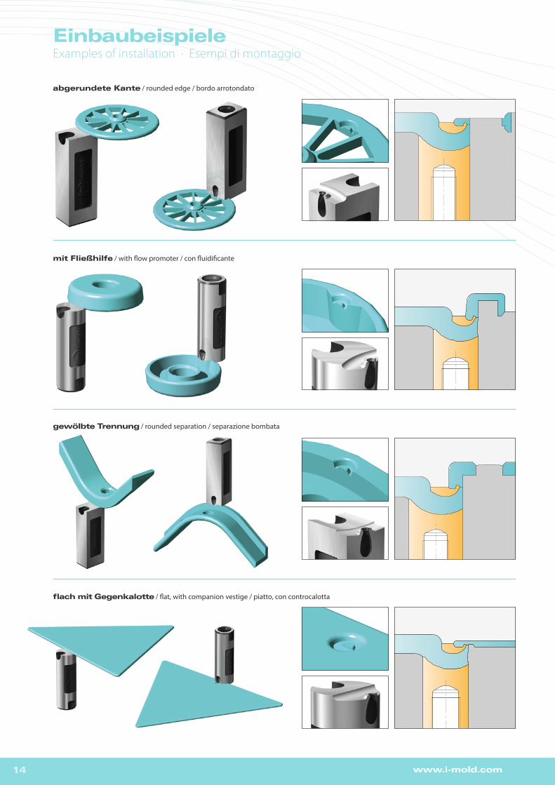
EinbaubeispieleExamples of installation · Esempi di montaggio
abgerundete Kante / rounded edge / bordo arrotondato
mit Fließhilfe / with flow promoter / con fluidificante
gewölbte Trennung / rounded separation / separazione bombata
flach mit Gegenkalotte / flat, with companion vestige / piatto, con controcalotta

15www.i-mold.com
EinbaubeispieleExamples of installation · Esempi di montaggio
TGC-XS TGC-S TGC-1 TGC-2 TGC-3 TGC-4
max. Konturtiefe / max. contour depth / max. profondità di contornatura 1 2 2 3 5 10
Anschnitt / gate point / punto d’iniezione 0,4 - 0,6 0,4 - 0,8 0,6 - 1,2 0,8 - 1,8 0,5x4,5 - 1,5x5,5 0,5x4,5 - 1,5x5,5
Ø Kanal / runner / canale 2.5 2.5 4 6 8 8
max. Schussgewichte (g) · max. shotweight (g) · pesi d‘iniezione max. (g)
NV 5 12 35 120 1000 1000
MV 4 7 25 75 500 500
HV 3 5 15 50 300 300
NV = niedrige Viskosität / low viscosity / bassa viscositàMV = mittlere Viskosität / medium viscosity / media viscositàHV = hohe Viskosität / high viscosity / elevata viscosità
TGC konturierbarcontourablecontornabile
DE >für Konturierungen bis zu 10mm >individuell anpassbar >in 2 Härteklassen (60 HRC / 40 HRC) erhältlich
EN > for contouring up to 10mm > individually adjustable > available in 2 degrees of hardness (60 HRC / 40 HRC)
IT > per contornature fino a 10mm > adattamento individuale > disponibile in 2 differenti durezze (60 HRC / 40 HRC)
TGC
TG
C
Optimal für spröde und verstärkte Kunststoffe · Perfect for rigid and enforced plastics · Adatto per ogni tipo di plastica

16 www.i-mold.com
TGC konturierbar · contourable · contornabile
Typ b b1 b2 d3 h h1 h2 h3 l1 l2 l3 M HRC
TGC-XS 10 5 8.5 2.5 12 1 1.9 0.6 5 3.2 0.7 4
Vers
ion
U =
40
HRC
Ve
rsio
n H
= 6
0 H
RC
TGC-S 15 6 13.3 2.5 18 2 3.5 1.5 8 4 0.9 4
TGC-1 18 8 16 4 22 2 3.5 1.3 9 5.2 0.9 5
TGC-2 25 10 22.1 6 22 3 4.8 2.1 8 6.5 1.2 5
TGC-3 30 12 26.9 8 27 5 7.5 4.1 9 7 1.2 6
TGC-4 45 12 41.2 8 36 10 16.7 9.1 8 9.6 1.8 6
Beispiel Bestellbezeichnung · Example of order specification · Esempio codice di ordinazione: TGC-XS-U
Diagramm für Abstandsmaß L · Table for distance L · Diagramma per la distanza L
Materialart · Material type · Tipo di materiale
TPE, TPU etc. PE, PP, PET etc. PC, ABS, PA, POM, HI-PC, etc. PA+GF, PC, SAN, PMMA etc.
TGC-XS 12-16 13-20 16-23 22-29
TGC-S 16-21 18-25 21-28 27-34
TGC-1 21-26 26-34 31-39 36-45
TGC-2 28-33 31-39 36-44 41-50
TGC-3 33-38 38-48 43-53 48-58TGC-4 48-53 53-63 58-68 ?
L
0.8
x L
TGC-XS / TGC-S min Ø3,5
LTGC-XS / TGC-S min Ø3,5
TPE< 100 Shore
h1
hl1
M
b2
d3
b
b1
l2
h3
l3
h2+0
,015
0 0 -0
,015
0-0,015
BearbeitungsbereichMachining areaAmbito di lavorazione
CAD
h1
hl1
M
b2
d3
b
b1
l2
h3
l3h2
+0,0
15 0
0 -0,0
15
0-0,015
BearbeitungsbereichMachining areaAmbito di lavorazione
CAD
DE Thermoplastische Elastomere (TPE) > Kleine Shorehärte = geringeres Abstandsmaß L > Zentrierzapfen verwenden > Shorehärte max. 100 Shore A
EN Thermoplastic elastomers (TPE) > Low Shore hardness = shorter distance L > Use centring pin > Max. hardness 100 Shore A
IT Elastomeri termoplastici (TPE) > Bassa durezza Shore = distanza L più ridotta > Utilizzare un perno di guida > Durezza: max. 100 Shore A
TGC-XS / TGC-S
M4
30
CAD
M4
BefestigungsmöglichkeitenMounting possibilities Possibilità di fissaggio
Kalottengestaltung > siehe ergänzende Tipps (Seite 36) · Vestige design > see additional tips (page 36) · Design della calotta à vedi dati aggiuntivi (pagina 36)
17www.i-mold.com
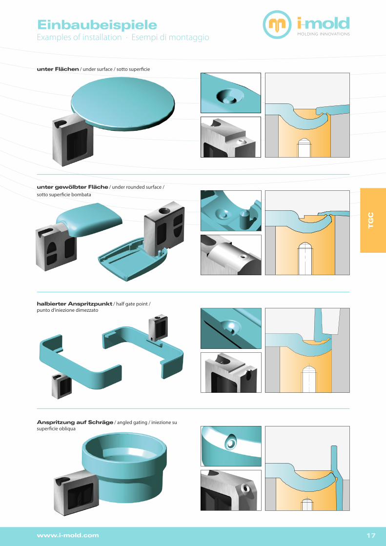
EinbaubeispieleExamples of installation · Esempi di montaggio
unter Flächen / under surface / sotto superficie
unter gewölbter Fläche / under rounded surface /sotto superficie bombata
halbierter Anspritzpunkt / half gate point / punto d’iniezione dimezzato
Anspritzung auf Schräge / angled gating / iniezione su superficie obliqua
TGC1_Halb
TGC-SCHRÄG
TG
C

18 www.i-mold.com
TGLL konturierbarcontourablecontornabile
TGLL
DE >platzsparender, konturierbarer Angusseinsatz für Anspritzung unterhalb der Formtrennung >hoch verschleißfester Warmarbeitsstahl M2 (1.3343) 54+2 HRC
EN > Space-saving, contourable Tunnel Gate insert for gating below the parting line > Highly wear resistant hot working steel M2 (1.3343) 54+2 HRC
IT > Inserto lavorabile, che fa risparmiare molto spazio, per punto d‘iniezione sotto la linea di divisione dello stampo > Acciaio per lavorazioni a coldo particolarmente resistente all`usura M2 (1.3343) 54+2 HRC
TGLL-1 TGLL-2 TGLL-3
max. Konturtiefe / max. contour depth / max. profondità di contornatura 8,5 10,5 12,5
Anschnitt / gate point / punto d’iniezione 0,6 - 1,2 0,8 - 1,8 0,5x4,5 - 1,5x5,5
Ø Kanal / runner / canale 4 6 8
max. Schussgewichte (g) · max. shotweight (g) · pesi d‘iniezione max. (g)
NV 35 120 1000
MV 25 75 500
HV 15 50 300
NV = niedrige Viskosität / low viscosity / bassa viscositàMV = mittlere Viskosität / medium viscosity / media viscositàHV = hohe Viskosität / high viscosity / elevata viscosità
Für spröde und verstärkte Kunststoffe bedingt geeignet · Restrictedly suitable for rigid and reinforced plastics · Adatto esclusivamente per plastiche rigide e rinforzate
19www.i-mold.com
TG
LL
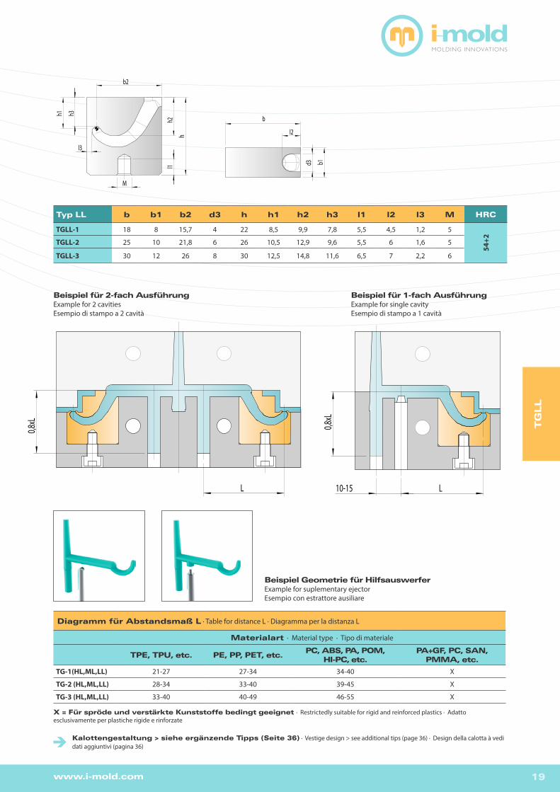
Typ LL b b1 b2 d3 h h1 h2 h3 l1 l2 l3 M HRC
TGLL-1 18 8 15,7 4 22 8,5 9,9 7,8 5,5 4,5 1,2 5
54+2TGLL-2 25 10 21,8 6 26 10,5 12,9 9,6 5,5 6 1,6 5
TGLL-3 30 12 26 8 30 12,5 14,8 11,6 6,5 7 2,2 6
Diagramm für Abstandsmaß L · Table for distance L · Diagramma per la distanza L
Materialart · Material type · Tipo di materiale
TPE, TPU, etc. PE, PP, PET, etc.PC, ABS, PA, POM,
HI-PC, etc.PA+GF, PC, SAN,
PMMA, etc.
TG-1(HL,ML,LL) 21-27 27-34 34-40 X
TG-2 (HL,ML,LL) 28-34 33-40 39-45 X
TG-3 (HL,ML,LL) 33-40 40-49 46-55 X
X = Für spröde und verstärkte Kunststoffe bedingt geeignet · Restrictedly suitable for rigid and reinforced plastics · Adatto esclusivamente per plastiche rigide e rinforzate
Beispiel Geometrie für HilfsauswerferExample for suplementary ejectorEsempio con estrattore ausiliare
Beispiel für 2-fach AusführungExample for 2 cavitiesEsempio di stampo a 2 cavità
L
0,8xL
Beispiel für 1-fach AusführungExample for single cavityEsempio di stampo a 1 cavità
0,8x
L
L10-15
h
l1
M
h2
b2
h1
l3
h3
b
l2
d3 b1
h
l1
M
h2
b2
h1
l3
h3
b
l2
d3 b1
Kalottengestaltung > siehe ergänzende Tipps (Seite 36) · Vestige design > see additional tips (page 36) · Design della calotta à vedi dati aggiuntivi (pagina 36)

20 www.i-mold.com
TGML konturierbarcontourablecontornabile
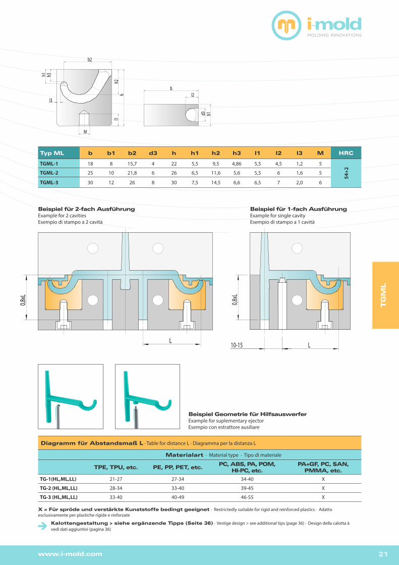
DE >platzsparender, konturierbarer Angusseinsatz für Anspritzung oberhalb der Formtrennung >hoch verschleißfester Warmarbeitsstahl M2 (1.3343) 54+2 HRC
EN > Space-saving, contourable Tunnel Gate insert for gating above the parting line > Highly wear resistant hot working steel M2 (1.3343) 54+2 HRC
IT > Inserto lavorabile, che fa risparmiare molto spazio, per punto d‘iniezione sotto la linea di divisione dello stampo > Acciaio per lavorazioni a coldo particolarmente resistente all`usura M2 (1.3343) 54+2 HRC
TGML
TGML-1 TGML-2 TGML-3
max. Konturtiefe / max. contour depth / max. profondità di contornatura 5,5 6,5 7,5
Anschnitt / gate point / punto d’iniezione 0,6 - 1,2 0,8 - 1,8 0,5x4,5 - 1,5x5,5
Ø Kanal / runner / canale 4 6 8
max. Schussgewichte (g) · max. shotweight (g) · pesi d‘iniezione max. (g)
NV 35 120 1000
MV 25 75 500
HV 15 50 300
NV = niedrige Viskosität / low viscosity / bassa viscositàMV = mittlere Viskosität / medium viscosity / media viscositàHV = hohe Viskosität / high viscosity / elevata viscosità
Für spröde und verstärkte Kunststoffe bedingt geeignet · Restrictedly suitable for rigid and reinforced plastics · Adatto esclusivamente per plastiche rigide e rinforzate
21www.i-mold.com
TG
ML
Typ ML b b1 b2 d3 h h1 h2 h3 l1 l2 l3 M HRC
TGML-1 18 8 15,7 4 22 5,5 9,5 4,86 5,5 4,5 1,2 5
54+2TGML-2 25 10 21,8 6 26 6,5 11,6 5,6 5,5 6 1,6 5
TGML-3 30 12 26 8 30 7,5 14,5 6,6 6,5 7 2,0 6
Diagramm für Abstandsmaß L · Table for distance L · Diagramma per la distanza L
Materialart · Material type · Tipo di materiale
TPE, TPU, etc. PE, PP, PET, etc.PC, ABS, PA, POM,
HI-PC, etc.PA+GF, PC, SAN,
PMMA, etc.
TG-1(HL,ML,LL) 21-27 27-34 34-40 X
TG-2 (HL,ML,LL) 28-34 33-40 39-45 X
TG-3 (HL,ML,LL) 33-40 40-49 46-55 X
X = Für spröde und verstärkte Kunststoffe bedingt geeignet · Restrictedly suitable for rigid and reinforced plastics · Adatto esclusivamente per plastiche rigide e rinforzate
Beispiel Geometrie für HilfsauswerferExample for suplementary ejectorEsempio con estrattore ausiliare
Beispiel für 2-fach AusführungExample for 2 cavitiesEsempio di stampo a 2 cavità
Beispiel für 1-fach AusführungExample for single cavityEsempio di stampo a 1 cavità
hh2
l1
M
b2
h3h1
l3
bl2
d3 b1
hh2
l1
M
b2
h3h1
l3
bl2
d3 b1
0,8xL
10-15 LL
0,8xL
Kalottengestaltung > siehe ergänzende Tipps (Seite 36) · Vestige design > see additional tips (page 36) · Design della calotta à vedi dati aggiuntivi (pagina 36)

22 www.i-mold.com
TGHL konturierbarcontourablecontornabile
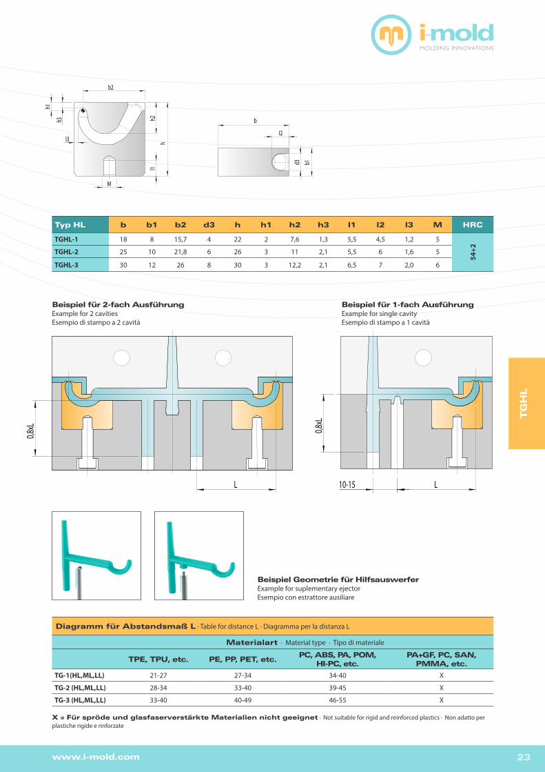
DE >platzsparender, konturierbarer Angusseinsatz für Anspritzung oberhalb der Formtrennung >hoch verschleißfester Warmarbeitsstahl M2 (1.3343) 54+2 HRC
EN > Space-saving, contourable Tunnel Gate insert for gating above the parting line > Highly wear resistant hot working steel M2 (1.3343) 54+2 HRC
IT > Inserto lavorabile, che fa risparmiare molto spazio, per punto d‘iniezione sotto la linea di divisione dello stampo > Acciaio per lavorazioni a coldo particolarmente resistente all`usura M2 (1.3343) 54+2 HRC
TGHL
TGHL-1 TGHL-2 TGHL-3
max. Konturtiefe / max. contour depth / max. profondità di contornatura 2 3 3
Anschnitt / gate point / punto d’iniezione 0,6 - 1,2 0,8 - 1,8 0,5x4,5 - 1,5x5,5
Ø Kanal / runner / canale 4 6 8
max. Schussgewichte (g) · max. shotweight (g) · pesi d‘iniezione max. (g)
NV 35 120 1000
MV 25 75 500
HV 15 50 300
NV = niedrige Viskosität / low viscosity / bassa viscositàMV = mittlere Viskosität / medium viscosity / media viscositàHV = hohe Viskosität / high viscosity / elevata viscosità
Kalotte nach 3D DatensatzVestige by 3D fileCalotta 3D
Für spröde und verstärkte Kunststoffe nicht geeignet · Not suitable for rigid and reinforced plastics · Non adatto per plastiche rigide e rinforzate.
23www.i-mold.com
Beispiel Geometrie für HilfsauswerferExample for suplementary ejectorEsempio con estrattore ausiliare
L
0,8xL
10-15L
0,8xL
hl1
h2
b2
h3
h1
l3
M
I2
d3 b1
b
hl1
h2
b2
h3
h1
l3
M
I2
d3 b1
b
TG
HL
Diagramm für Abstandsmaß L · Table for distance L · Diagramma per la distanza L
Materialart · Material type · Tipo di materiale
TPE, TPU, etc. PE, PP, PET, etc.PC, ABS, PA, POM,
HI-PC, etc.PA+GF, PC, SAN,
PMMA, etc.
TG-1(HL,ML,LL) 21-27 27-34 34-40 X
TG-2 (HL,ML,LL) 28-34 33-40 39-45 X
TG-3 (HL,ML,LL) 33-40 40-49 46-55 X
X = Für spröde und glasfaserverstärkte Materialien nicht geeignet · Not suitable for rigid and reinforced plastics · Non adatto per plastiche rigide e rinforzate
Beispiel für 2-fach AusführungExample for 2 cavitiesEsempio di stampo a 2 cavità
Beispiel für 1-fach AusführungExample for single cavityEsempio di stampo a 1 cavità
Typ HL b b1 b2 d3 h h1 h2 h3 l1 l2 l3 M HRC
TGHL-1 18 8 15,7 4 22 2 7,6 1,3 5,5 4,5 1,2 5
54+2TGHL-2 25 10 21,8 6 26 3 11 2,1 5,5 6 1,6 5
TGHL-3 30 12 26 8 30 3 12,2 2,1 6,5 7 2,0 6
24 www.i-mold.com
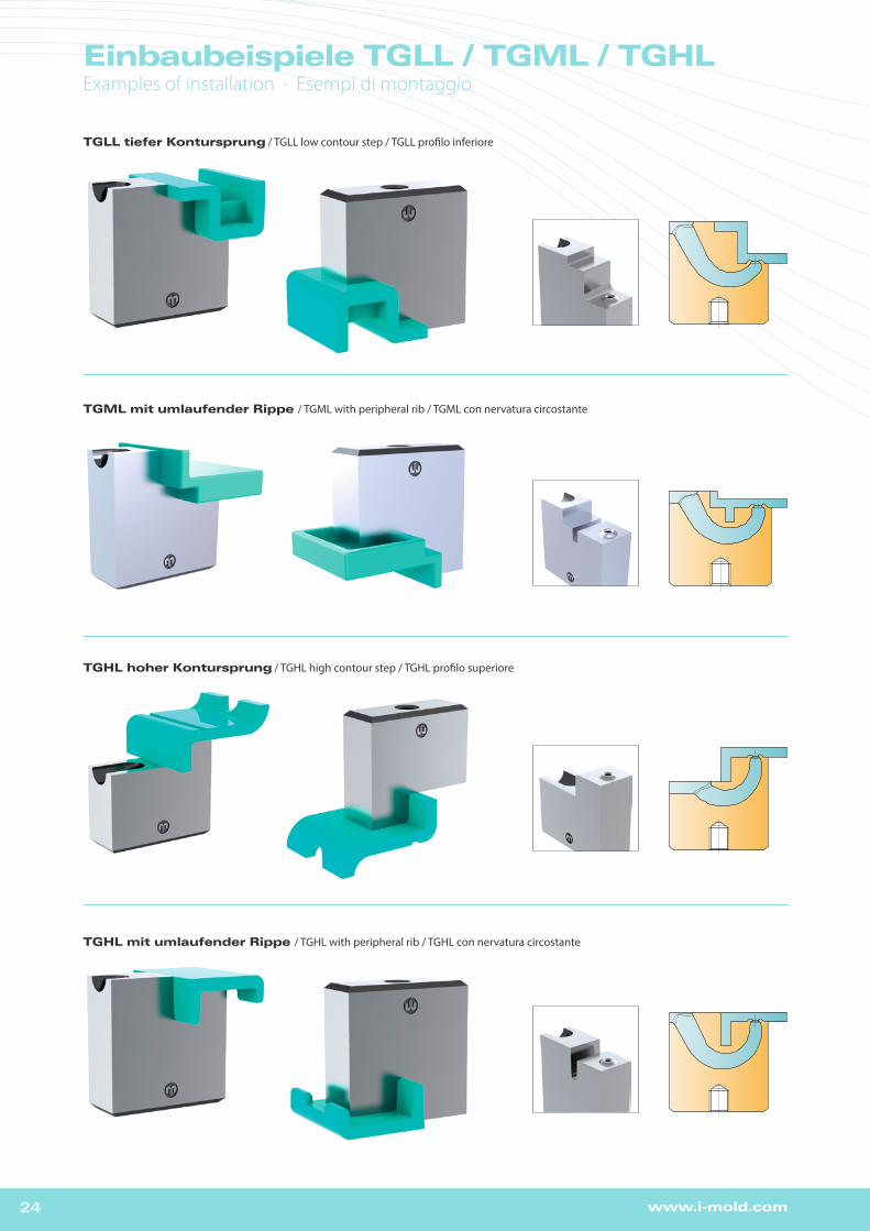
Einbaubeispiele TGLL / TGML / TGHLExamples of installation · Esempi di montaggio
TGLL tiefer Kontursprung / TGLL low contour step / TGLL profilo inferiore
TGHL hoher Kontursprung / TGHL high contour step / TGHL profilo superiore
TGHL mit umlaufender Rippe / TGHL with peripheral rib / TGHL con nervatura circostante
TGML mit umlaufender Rippe / TGML with peripheral rib / TGML con nervatura circostante
25www.i-mold.com
Einbaubeispiele TGLL / TGML / TGHLExamples of installation · Esempi di montaggio
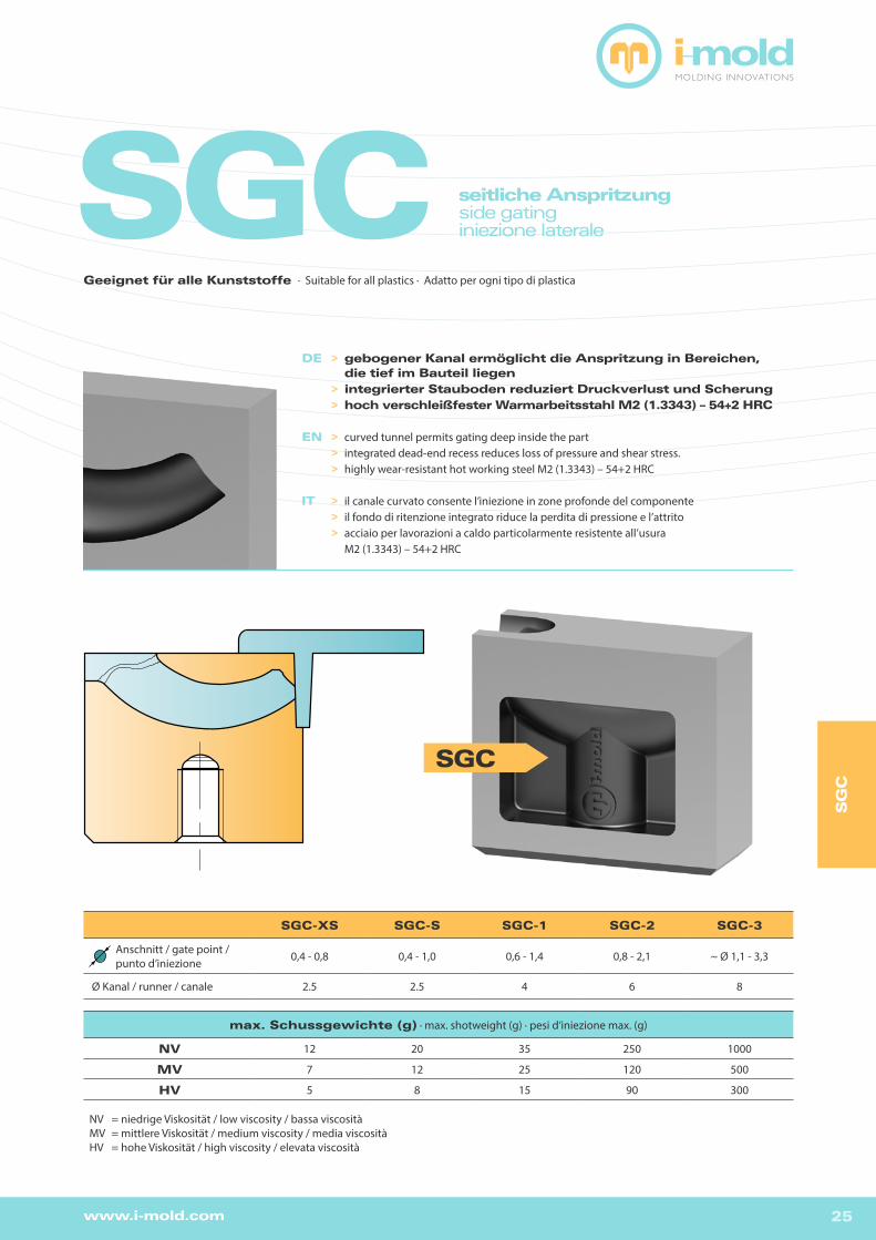
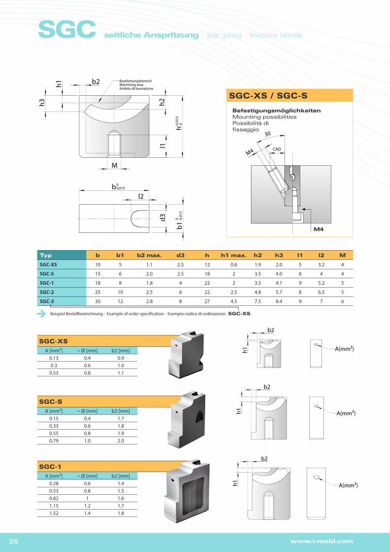
SGC seitliche Anspritzungside gatinginiezione laterale
DE >gebogener Kanal ermöglicht die Anspritzung in Bereichen, die tief im Bauteil liegen >integrierter Stauboden reduziert Druckverlust und Scherung >hoch verschleißfester Warmarbeitsstahl M2 (1.3343) – 54+2 HRC
EN > curved tunnel permits gating deep inside the part > integrated dead-end recess reduces loss of pressure and shear stress. > highly wear-resistant hot working steel M2 (1.3343) – 54+2 HRC
IT > il canale curvato consente l’iniezione in zone profonde del componente > il fondo di ritenzione integrato riduce la perdita di pressione e l’attrito > acciaio per lavorazioni a caldo particolarmente resistente all’usura M2 (1.3343) – 54+2 HRC
SGC
SGC-XS SGC-S SGC-1 SGC-2 SGC-3
Anschnitt / gate point /punto d’iniezione 0,4 - 0,8 0,4 - 1,0 0,6 - 1,4 0,8 - 2,1 ~ Ø 1,1 - 3,3
Ø Kanal / runner / canale 2.5 2.5 4 6 8
max. Schussgewichte (g) · max. shotweight (g) · pesi d‘iniezione max. (g)
NV 12 20 35 250 1000
MV 7 12 25 120 500
HV 5 8 15 90 300
NV = niedrige Viskosität / low viscosity / bassa viscositàMV = mittlere Viskosität / medium viscosity / media viscositàHV = hohe Viskosität / high viscosity / elevata viscosità
SG
C
Geeignet für alle Kunststoffe · Suitable for all plastics · Adatto per ogni tipo di plastica
26 www.i-mold.com
SGC seitliche Anspritzung · side gating · iniezione laterale
Typ b b1 b2 max. d3 h h1 max. h2 h3 l1 l2 M
SGC-XS 10 5 1.1 2.5 12 0.6 1.9 2.0 5 3.2 4
SGC-S 15 6 2.0 2.5 18 2 3.5 4.0 8 4 4
SGC-1 18 8 1.8 4 22 2 3.5 4.1 9 5.2 5
SGC-2 25 10 2.5 6 22 2.5 4.8 5.7 8 6.5 5
SGC-3 30 12 2.8 8 27 4.5 7.5 8.4 9 7 6
Beispiel Bestellbezeichnung · Example of order specification · Esempio codice di ordinazione: SGC-XS
SGC-1
A [mm²] ~ Ø [mm] b2 [mm]0.28 0.6 1.40.53 0.8 1.50.82 1 1.61.15 1.2 1.71.52 1.4 1.8
BefestigungsmöglichkeitenMounting possibilities Possibilità di fissaggio
SGC-XS
A [mm²] ~ Ø [mm] b2 [mm]0.13 0.4 0.90.3 0.6 1.0
0.53 0.8 1.1
SGC-S
A [mm²] ~ Ø [mm] b2 [mm]0.15 0.4 1.70.33 0.6 1.80.55 0.8 1.90.79 1.0 2.0
l1
M
h
h1
h3b2
bb1
d3
l2
h2
0-0,015
0 -0,0
15+0
,015
0
BearbeitungsbereichMachining areaAmbito di lavorazione
l1M
h
h1
h3
b2
b
b1
d3
l2
h2
0-0,015
0 -0,0
15+0
,015
0
BearbeitungsbereichMachining areaAmbito di lavorazione
h1
b2
h1
b2
h1
b2
h1
b2
h1
b2
SGC3
SGC2
SGC1
SGC-S
SGC-XS
A(mm2)
A(mm2)A(mm2)
A(mm2)
A(mm2)
h1
b2
h1
b2
h1
b2
h1
b2
h1
b2
SGC3
SGC2
SGC1
SGC-S
SGC-XS
A(mm2)
A(mm2)A(mm2)
A(mm2)
A(mm2)h1
b2
h1
b2
h1
b2
h1
b2
h1
b2
SGC3
SGC2
SGC1
SGC-S
SGC-XS
A(mm2)
A(mm2)A(mm2)
A(mm2)
A(mm2)
h1
b2
h1
b2
h1
b2
h1
b2
h1
b2
SGC3
SGC2
SGC1
SGC-S
SGC-XS
A(mm2)
A(mm2)A(mm2)
A(mm2)
A(mm2)
h1
b2
h1
b2
h1
b2
h1
b2
h1
b2
SGC3
SGC2
SGC1
SGC-S
SGC-XS
A(mm2)
A(mm2)A(mm2)
A(mm2)
A(mm2)
h1
b2
h1
b2
h1
b2
h1
b2
h1
b2
SGC3
SGC2
SGC1
SGC-S
SGC-XS
A(mm2)
A(mm2)A(mm2)
A(mm2)
A(mm2)
SGC-XS / SGC-S
M4
30
CAD
M4
27www.i-mold.com
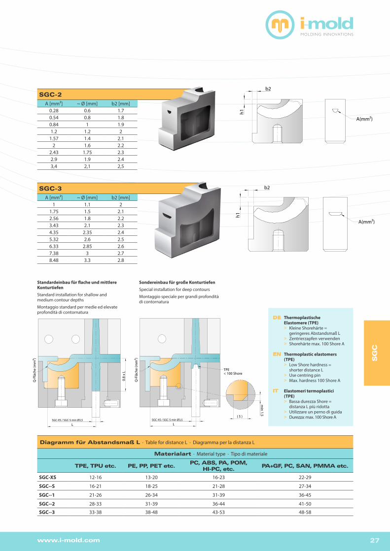
Diagramm für Abstandsmaß L · Table for distance L · Diagramma per la distanza L
Materialart · Material type · Tipo di materiale
TPE, TPU etc. PE, PP, PET etc.PC, ABS, PA, POM,
HI-PC, etc.PA+GF, PC, SAN, PMMA etc.
SGC-XS 12-16 13-20 16-23 22-29
SGC--S 16-21 18-25 21-28 27-34
SGC--1 21-26 26-34 31-39 36-45
SGC--2 28-33 31-39 36-44 41-50
SGC--3 33-38 38-48 43-53 48-58
SGC-2
A [mm²] ~ Ø [mm] b2 [mm]0.28 0.6 1.70.54 0.8 1.80.84 1 1.91.2 1.2 2
1.57 1.4 2.12 1.6 2.2
2.43 1.75 2.32.9 1.9 2.43,4 2,1 2,5
SGC-3
A [mm²] ~ Ø [mm] b2 [mm]1 1.1 2
1.75 1.5 2.12.56 1.8 2.23.43 2.1 2.34.35 2.35 2.45.32 2.6 2.56.33 2.85 2.67.38 3 2.78.48 3.3 2.8
h1
b2
h1
b2
h1
b2
h1
b2
h1
b2
SGC3
SGC2
SGC1
SGC-S
SGC-XS
A(mm2)
A(mm2)A(mm2)
A(mm2)
A(mm2)
h1
b2
h1
b2
h1
b2
h1
b2
h1
b2
SGC3
SGC2
SGC1
SGC-S
SGC-XS
A(mm2)
A(mm2)A(mm2)
A(mm2)
A(mm2)
h1
b2
h1
b2
h1
b2
h1
b2
h1
b2
SGC3
SGC2
SGC1
SGC-S
SGC-XS
A(mm2)
A(mm2)A(mm2)
A(mm2)
A(mm2)
0.8
x L
L
Q-F
läch
e (m
m2)
SGC-XS / SGC-S min Ø3,5
Standardeinbau für flache und mittlere KonturtiefenStandard installation for shallow and medium contour depths
Montaggio standard per medie ed elevate profondità di contornatura
Sondereinbau für große KonturtiefenSpecial installation for deep contours
Montaggio speciale per grandi profondità di contornatura
DE Thermoplastische Elastomere (TPE) > Kleine Shorehärte = geringeres Abstandsmaß L > Zentrierzapfen verwenden > Shorehärte max. 100 Shore A
EN Thermoplastic elastomers (TPE) > Low Shore hardness = shorter distance L > Use centring pin > Max. hardness 100 Shore A
IT Elastomeri termoplastici (TPE) > Bassa durezza Shore = distanza L più ridotta > Utilizzare un perno di guida > Durezza: max. 100 Shore A
L
min 1.5
( 5 )
Q-F
läch
e (m
m2)
TPE< 100 Shore
SGC-XS / SGC-S min Ø3,5
SG
C
28 www.i-mold.com
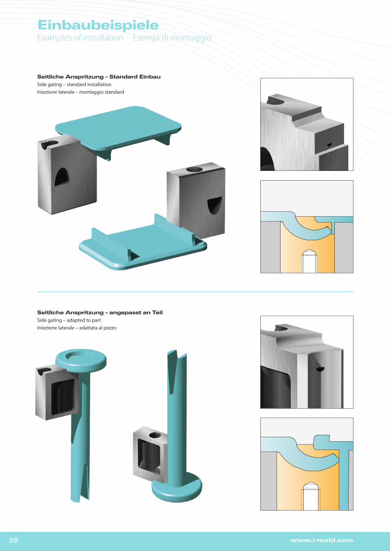
Seitliche Anspritzung – Standard Einbau
Side gating – standard installationIniezione laterale – montaggio standard
EinbaubeispieleExamples of installation · Esempi di montaggio
Seitliche Anspritzung – angepasst an Teil
Side gating – adapted to partIniezione laterale – adattata al pezzo

29www.i-mold.com
EinbaubeispieleExamples of installation · Esempi di montaggio
TPS seitliche Anspritzungside gatinginiezione laterale
DE >standardisierter Spitztunnel zur seitlichen Anspritzung >integrierter Stauboden reduziert Druckverlust und Scherung >hoch verschleißfester Warmarbeitsstahl M2 (1.3343) – 54+2 HRC
EN > straight standard sub-gate for side-gating > integrated dead-end recess reduces loss of pressure and shear stress. > highly wear-resistant hot working steel M2 (1.3343) – 54+2 HRC
IT > tunnel di iniezione standard per iniezione laterale > il fondo di ritenzione integrato riduce la perdita di pressione e l’attrito > acciaio per lavorazioni a caldo particolarmente resistente all’usura M2 (1.3343) – 54+2 HRC
TPS-S TPS-1 TPS-2 TPS-3
Anschnitt / gate point /punto d’iniezione 0,4 - 0,8 0,8 - 1,8 0,8 - 2,8 1,1 - 4,5
max. Schussgewichte (g) · max. shotweight (g) · pesi d‘iniezione max. (g)
NV 30 120 600 1800
MV 20 75 350 1000
HV 12 50 175 600
NV = niedrige Viskosität / low viscosity / bassa viscositàMV = mittlere Viskosität / medium viscosity / media viscositàHV = hohe Viskosität / high viscosity / elevata viscosità
TPS
TP
S
Geeignet für alle Kunststoffe · Suitable for all plastics · Adatto per ogni tipo di plastica

30 www.i-mold.com
Typ b b1 b2 max. d3 h h1 max. h3 l1 l2 l3 M
TPS-S 15 6 2.4 4 18 4 ~7 6 7.1 5.5 4
TPS-1 18 8 2.6 6 22 5 ~9 6 8.4 6 4
TPS-2 25 10 5 8 22 6 ~11 6 11.8 7.5 5
TPS-3 30 12 6.5 10 27 7 ~13 6 14.1 8 5
Beispiel Bestellbezeichnung · Example of order specification · Esempio codice di ordinazione: TPS-1
BefestigungsmöglichkeitenMounting possibilities Possibilità di fissaggio
TPS-S
A [mm²] ~ Ø [mm] b2 [mm]0.12 0.4 2.10.40 0.7 2.20.75 1.0 2.31.13 1.2 2.4
TPS-1
A [mm²] ~ Ø [mm] b2 [mm]0.49 0.8 2.20.92 1.1 2.31.42 1.4 2.41.97 1.6 2.52.56 1.8 2.6
TPS
h3
b2
M
l1h
l3
h1
0+0
.015
BearbeitungsbereichMachining areaArea di lavorazione
b
d3
l2
b1
0-0.015
0 -0.01
5
h3
b2
M
l1h
l3
h1
0+0
.015
BearbeitungsbereichMachining areaArea di lavorazione
b
d3
l2
b1
0-0.015
0 -0.01
5
M4
30°
CAD
Befestigung über Madenschraube M4Fixed with headless screw M4Fissaggio mediante vite senza testa M4
Befestigung über Zylinderschraube M4Fixed with hexagon screw M4
Fissaggio mediante vite a testa cilindrica M4
b
A(mm²)
b
A(mm²)
TPS S2 Z3
TPS S2 Z4
b
A(mm²)
b
A(mm²)
TPS S2 Z3
TPS S2 Z4
TPS seitliche Anspritzung · side gating · iniezione laterale
31www.i-mold.com
Diagramm für Abstandsmaß L · Table for distance L · Diagramma per la distanza L
Materialart · Material type · Tipo di materiale
flexible Materialienflexible materials · materiali flessibili
steife Materialienrigid materials · materiali rigidi
TPS-S ~ 18 ~ 23
TPS-1 ~ 22 ~ 30
TPS-2 ~ 28 ~ 38
TPS-3 ~ 33 ~ 47
TPS-2
A [mm²] ~ Ø [mm] b2 [mm]0.54 0.8 4.21.05 1.2 4.31.64 1.5 4.42.3 1.7 4.53.0 1.9 4.6
3.76 2.2 4.74.55 2.4 4.85.37 2.6 4.96.23 2.8 5.0
TPS-3
A [mm²] ~ Ø [mm] b2 [mm]1.0 1.1 5.2
1.81 1.5 5.32.7 1.9 5.4
3.67 2.2 5.54.7 2.4 5.6
5.78 2.7 5.76.92 3.0 5.88.09 3.2 5.99.3 3.4 6.0
max. 15.8 4.5 6.5
Standardeinbau für flache und mittlere KonturtiefenStandard installation for shallow and medium contour depths
montaggio standard per pareti di bassa e media profondità
Sondereinbau für große KonturtiefenSpecial installation for deep contours
montaggio standard per pareti di alta profondità
DE Thermoplastische Elastomere (TPE) > Niedrige Shorehärte = geringeres Abstandsmaß L > Zentrierzapfen verwenden > Shorehärte max. 100 Shore A
EN Thermoplastic elastomers (TPE) > Low Shore hardness = shorter distance L > Use centring pin > Max. hardness 100 Shore A
IT Elastomeri termoplastici (TPE) > Bassa durezza Shore = distanza L più ridotta > Utilizzare un perno di guida > Durezza: max. 100 Shore A
TPS S3 Z1
TPS S3 Z2
b
A(mm²)
b
A(mm²)
max
.0,8
x L
L
cros
s-se
ctio
n (m
m2)
L
cros
s-se
ctio
n (m
m2)
~11
~3
TPE< 100 Shore A
TPS S3 Z1
TPS S3 Z2
b
A(mm²)
b
A(mm²)
TP
S
32 www.i-mold.com
EinbaubeispieleExamples of installation · Esempi di montaggio
Seitliche Anspritzung – für flache KonturtiefenSide gating – for flat contoursIniezione per pareti laterali poco profonde
Seitliche Anspritzung – für große KonturtiefenSide gating – for deep contoursiniezione per pareti laterali molto profonde
Seitliche Anspritzung – Standard EinbauSide gating – standard installationIniezione laterale – montaggio standard

33www.i-mold.com
ØH
124
32
l2
d2
d2
6 0 -0.0
2
d3
d1
d4
l1
4
l
+0,1 0
k6
+0,5
+0,
2 H7
l l1 l2 d1 d2 d3 d4 Order No:
36 36
7 12 4 16 4.5
RB4-36
4646
RB4-46
56 RB4-56
36 36
7 18 6 22 6.5
RB6-36
46 46 RB6-46
5656
RB6-56
66 RB6-66
46 46
9.5 24 8 28 8.5
RB8-46
56 56 RB8-56
66 66 RB8-66
Material: 2826 ~58 HRC
Haltebuchse
Haltebuchse
Retaining bushBoccola di arresto
HA
LT
EB
UC
HS
ER
ETA
ININ
G B
US
HB
OC
CO
LA
DI A
RR
ES
TO
34 www.i-mold.com
DE_Zur Anspritzung von Gehäuseteilen empfehlen wir einen Stauboden in ein Hilfsplättchen oder direkt in den Formeinsatz einzubringen. Der Stau-boden verringert die Schergeschwindigkeit im Anschnittbereich, verbessert den Quellfluss, reduziert den Druckverlust und wirkt der Freistrahlbildung entgegen.
EN_For the gating of housing parts we recommend incorporating a dead-end recess in an auxiliary insert or directly in the mould insert. This feature optimizes the shear velocity in the gate area, gives a superior frontal flow, reduces the pressure loss and helps prevent jetting.
IT_Per l’iniezione di parti di contenitori consigliamo di inserire un fondo di ritenzione in una piastrina ausiliare o direttamente nell’inserto dello stampo. Il fondo di ritenzione riduce la velocità di taglio nella zona d’iniezione, migliora il flusso laminare, riduce la perdita di pressione e previene la formazione di un getto libero.
DE_Beim Fertigen des Staubodens sollte darauf geachtet werden, dass keinHinterschnitt zum Angusskanal entsteht. Die 3D-Daten für die jeweilige Größeder Standard-Angusseinsätze finden Sie unter www.i-mold.de im Download-bereich.
EN_When machining the recess, take care to avoid undercutting the runner. For 3D data relating to standard insert sizes please refer to www.i-mold.com (download section).
IT_Per la realizzazione del fondo di ritenzione si deve fare attenzione ad evitare un sotto squadra verso il canale di alimentazione. I dati 3D per le rispettive dimensioni degli inserti d’iniezione standard possono essere scaricati presso www.i-mold.com nell’area di download.
15° b h1
a
HilfskernAuxiliary coreLe coeur auxiliaire
15° b h1
a
HilfskernAuxiliary coreLe coeur auxiliaire
15° b h1
a
HilfskernAuxiliary coreLe coeur auxiliaire
15° b h1
a
HilfskernAuxiliary coreLe coeur auxiliaire
DE_Gegenkalotte und/oder Stauboden können auch direkt in den Form-einsatz eingebracht werden. Das Hilfsplättchen sollte aus einem hoch ver-schleißfesten Stahl hergestellt werden.
Maße a, b und h1 sind vom jeweiligen Standard-Angusseinsatz abhängig.
EN_The companion vestige and/or dead-end recess can also be incorpo-rated directly in the mould insert. The auxiliary insert should be made of a highly wear-resistant steel.
The dimensions a, b and h1 depend on the actual standard gate insert used.
IT_La controcalotta e/o il fondo di ritenzione possono anche essere inseriti direttamente nell’inserto dello stampo. Per la piastrina ausiliare si dovrebbe utilizzare un acciaio particolarmente resistente all’usura.
Le misure a, b e h1 dipendono dal rispettivo inserto d‘iniezione standard.
Ergänzende Tipps Supplementary tips · Consigli supplementari
Stauboden · Dead-end recess · Fondo di ritenzione
Stauboden-Elektrode · Spark-erosion machining of recesses · Elettrodo del fondo di ritenzione
Hilfsplättchen · Auxiliary insert · Piastrine ausiliari
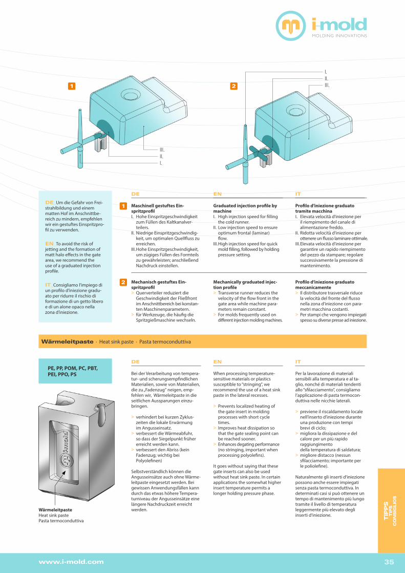
35www.i-mold.com
III. II.I.
DE
Bei der Verarbeitung von tempera-tur- und scherungsempfindlichen Materialien, sowie von Materialien, die zu „Fadenzug“ neigen, emp-fehlen wir, Wärmeleitpaste in die seitlichen Aussparungen einzu-bringen.
> verhindert bei kurzen Zyklus- zeiten die lokale Erwärmung im Angusseinsatz.> verbessert die Wärmeabfuhr, so dass der Siegelpunkt früher erreicht werden kann.> verbessert den Abriss (kein Fadenzug; wichtig bei Polyolefinen)
Selbstverständlich können die Angusseinsätze auch ohne Wärme-leitpaste eingesetzt werden. Bei gewissen Anwendungsfällen kann durch das etwas höhere Tempera-turniveau der Angusseinsätze eine längere Nachdruckzeit erreicht werden.Wärmeleitpaste
Heat sink pastePasta termoconduttiva
PE, PP, POM, PC, PBT, PEI, PPO, PS
Wärmeleitpaste · Heat sink paste · Pasta termoconduttiva
EN
When processing temperature-sensitive materials or plastics susceptible to “stringing”, we recommend the use of a heat sink paste in the lateral recesses.
> Prevents localized heating of the gate insert in molding processes with short cycle times.> Improves heat dissipation so that the gate sealing point can be reached sooner.> Enhances degating performance (no stringing, important when processing polyolefins).
It goes without saying that these gate inserts can also be used without heat sink paste. In certain applications the somewhat higher insert temperature permits a longer holding pressure phase.
IT
Per la lavorazione di materiali sensibili alla temperatura e al ta-glio, nonché di materiali tendenti allo “sfilacciamento”, consigliamo l’applicazione di pasta termocon-duttiva nelle nicchie laterali.
> previene il riscaldamento locale nell’inserto d’iniezione durante una produzione con tempi brevi di ciclo;> migliora la dissipazione e del calore per un più rapido raggiungimento della temperatura di saldatura;> migliore distacco (nessun sfilacciamento; importante per le poliolefine).
Naturalmente gli inserti d‘iniezione possono anche essere impiegati senza pasta termoconduttiva. In determinati casi si può ottenere un tempo di mantenimento più lungo tramite il livello di temperatura leggermente più elevato degli inserti d‘iniezione.
DE_Um die Gefahr von Frei- strahlbildung und einem matten Hof im Anschnittbe-reich zu mindern, empfehlen wir ein gestuftes Einspritzpro-fil zu verwenden.
EN_To avoid the risk of jetting and the formation of matt halo effects in the gate area, we recommend the use of a graduated injection profile.
IT_Consigliamo l’impiego di un profilo d’iniezione gradu-ato per ridurre il rischio di formazione di un getto libero e di un alone opaco nella zona d’iniezione.
I. II.III.
DE
Maschinell gestuftes Ein- spritzprofilI. Hohe Einspritzgeschwindigkeit zum Füllen des Kaltkanalver- teilers.II. Niedrige Einspritzgeschwindig- keit, um optimalen Quellfluss zu erreichen.III. Hohe Einspritzgeschwindigkeit, um zügiges Füllen des Formteils zu gewährleisten; anschließend Nachdruck einstellen.
Mechanisch gestuftes Ein- spritzprofil> Querverteiler reduziert die Geschwindigkeit der Fließfront im Anschnittbereich bei konstan- ten Maschinenparametern.> für Werkzeuge, die häufig die Spritzgießmaschine wechseln.
EN
Graduated injection profile by machineI. High injection speed for filling the cold runner.II. Low injection speed to ensure optimum frontal (laminar) flow.III. High injection speed for quick mold filling, followed by holding pressure setting.
Mechanically graduated injec-tion profile> Transverse runner reduces the velocity of the flow front in the gate area while machine para- meters remain constant.> For molds frequently used on different injection molding machines.
IT
Profilo d’iniezione graduato tramite macchinaI. Elevata velocità d‘iniezione per il riempimento del canale di alimentazione freddo.II. Ridotta velocità d‘iniezione per ottenere un flusso laminare ottimale.III. Elevata velocità d‘iniezione per garantire un rapido riempimento del pezzo da stampare; regolare successivamente la pressione di mantenimento.
Profilo d’iniezione graduato meccanicamente> Il distributore trasversale riduce la velocità del fronte del flusso nella zona d’iniezione con para- metri macchina costanti.> Per stampi che vengono impiegati spesso su diverse presse ad iniezione.
1
2
1 2
TIP
PS
TIP
SC
ON
SIG
LIO
S
36 www.i-mold.com
27+0
.015
0
()
7.5
26.9
30 0-0.015
( )1.2
9
12 0 -0
.015
7
Ø8
5.5
max:1.5
60°
R3.4
()
-1.0
9.0
5.5
5
4.5
max: .01
60°
4.75
M6
8.0
.05
R2.7
R0.3R0.3
()
-0.9
()
4.1
5
0.25
Große KalotteKleine Kalotte
"X""X"
"Y" "Y"
Y
X
27+0
.015
0
()
7.5
26.9
30 0-0.015
( )1.2
9
12 0 -0
.015
7
Ø8
5.5
max:1.5
60°
R3.4
()
-1.0
9.0
5.5
5
4.5
max: .01
60°
4.75
M6
8.0
.05
R2.7
R0.3R0.3
()
-0.9
()
4.1
5
0.25
Große KalotteKleine Kalotte
"X""X"
"Y" "Y"
Y
X
27+0
.015
0
()
7.5
26.9
30 0-0.015
( )1.2
9
12 0 -0
.015
7
Ø8
5.5
max:1.5
60°
R3.4
()
-1.0
9.0
5.5
5
4.5
max: .01
60°
4.75
M6
8.0
.05
R2.7
R0.3R0.3
()
-0.9
()
4.1
5
0.25
Große KalotteKleine Kalotte
"X""X"
"Y" "Y"
Y
X
27+0
.015
0
()
7.5
26.9
30 0-0.015
( )1.2
9
12 0 -0
.015
7
Ø8
5.5
max:1.5
60°
R3.4
()
-1.0
9.0
5.5
5
4.5
max: .01
60°
4.75
M6
8.0
.05
R2.7
R0.3R0.3
()
-0.9
()
4.1
5
0.25
Große KalotteKleine Kalotte
"X""X"
"Y" "Y"
Y
X
Standard-KalotteStandard vestige · Calotta standard
Kleine KalotteSmall vestige · Calotta piccola
h1
h1
Ø dk
RK
Ø dk
RK
Ø d1
Ø d1
18 0-0.015
22+0
.015
0
M5
9
16
()
3.5
8 0 -0
.015
Ø4
()
1.3
5.2
( )0.9
60°
R0.3R0.3
2
Große Kalotte
Kleine Kalotte
60°
Z
h1
h1
Ø dk
RK
Ø dk
RK
Ø d1
Ø d1
18 0-0.015
22+0
.015
0
M5
9
16
()
3.5
8 0 -0
.015
Ø4
()
1.3
5.2
( )0.9
60°
R0.3R0.3
2
Große Kalotte
Kleine Kalotte
60°
Z
Ergänzende Tipps Supplementary tips · Consigli supplementari
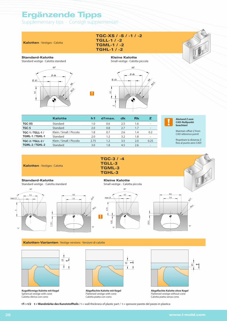
Kalotten · Vestiges · Calotta
TGC-XS / -S / -1 / -2TGLL-1 / -2TGML-1 / -2TGHL-1 / -2
Kugelförmige Kalotte mit Kegel Spherical vestige with coneCalotta sferica con cono
Abgeflachte Kalotte mit KegelFlattened vestige with coneCalotta piatta con cono
Abgeflachte Kalotte ohne Kegel Flattened vestige without coneCalotta piatta senza cono
Kalotten-Varianten · Vestige versions · Versioni di calotte
t1
t1
t1
t t t
Kalotten Varianten / variant of coni cal vestige / variant of conical ves tiget1>t/2 (t= Wandstärke des Kunststoff teils / t=wall thickness plastic par t / t=wall thickness plastic part)
Kugelförmige Kalotte mit Kegelspherical vestige with conespherical vestige with cone
Abgeflachte Kalotte mit Kegelflat vestige with coneflat vestige with cone
Abgeflachte Kalotte ohne Kegelflat vestige without coneflat vestige without cone
t1
t1
t1
t t t
Kalotten Varianten / variant of coni cal vestige / variant of conical ves tiget1>t/2 (t= Wandstärke des Kunststoff teils / t=wall thickness plastic par t / t=wall thickness plastic part)
Kugelförmige Kalotte mit Kegelspherical vestige with conespherical vestige with cone
Abgeflachte Kalotte mit Kegelflat vestige with coneflat vestige with cone
Abgeflachte Kalotte ohne Kegelflat vestige without coneflat vestige without cone
Standard-KalotteStandard vestige · Calotta standard
Kleine KalotteSmall vestige · Calotta piccola
Kalotte h1 d1max. dk Rk Z
TGC-XS Standard 1.0 0.6 2.5 1.6 -TGC-S Standard 2.0 0.8 2.7 1.7 -
TGC-1 / TGLL-1 / TGML-1 / TGHL-1
Klein / Small / Piccolo 1.8 0.7 2.6 1.4 0.2Standard 2.0 1.2 3.2 1.8 -
TGC-2 / TGLL-2 / TGML-2 / TGHL-2
Klein / Small / Piccolo 2.75 1.2 3.5 2.0 0.25Standard 3.0 1.8 4.5 2.6 -
Abstand Z zum CAD-Nullpunkt beachten!
Maintain offset Z from CAD reference point!
Rispettare la distanza Z fino al punto zero CAD!
t1 > t/2 t = Wandstärke des Kunststoffteils / t = wall thickness of plastic part / t = spessore parete del pezzo in plastica
Kalotten · Vestiges · Calotta
TGC-3 / -4TGLL-3TGML-3TGHL-3

37www.i-mold.com
9 5
R2.5
30°Z
Elektrode_Kalotte
Anschnitt ErodierenSpark erosion of gate area
Elettroerosione del punto di iniezione
Anschnitt FräsenMilling of gate area
Fresatura del punto d’iniezione
Querschnittsfläche [mm²] Cross-sectional area [mm²]Superficie trasversale [mm²]
Elektrodentiefe Z [mm]Electrode depth Z [mm]
Profondità elettrodo Z [mm]
Breite X [mm]Width X [mm]
Larghezza X [mm]
Länge Y [mm]Length Y [mm]
Lunghezza Y [mm
7,60 -0,86 1,5 5,57,00 -0,74 1,4 5,46,41 -0,62 1,3 5,35,84 -0,49 1,2 5,25,27 -0,37 1,1 5,14,72 -0,25 1,0 5.04,18 -0,13 0,9 4,93,65 -0,01 0,8 4,83,13 +0,11 0,7 4,72,63 +0,23 0,6 4,62,14 +0,35 0,5 4,5
DE Fertigung des Anschnitts mittels Elektrode >einfaches Platzieren der Elektrode über Koordinatensystem >2D- und 3D- Geometrie der Elektrode unter www.i-mold.de (Downloadbereich)
EN Gate machining by spark erosion >Simple positioning of electrode via coordinate system >For 2D and 3D electrode geometry please refer to www.i-mold.com (download section)
IT Realizzazione del punto d’iniezione tramite elettrodo > facile posizionamento dell’elettrodo tramite un sistema di coordinate >geometria 2D e 3D dell’elettrodo presso www.i-mold.com (area di download)
X Y
Maße für Fräßer
VW
V W
X Y
Maße für Fräßer
VW
V W
Anschnitt Erodieren* · Spark erosion of gate area · Elettroerosione del punto d’iniezione
Anschnitt Fräsen* · Milling of gate area · Fresatura del punto d’iniezione
DE Fertigung des Anschnitts mittels Fräsen >einfaches Fertigen des Anschnitts über Verfahren in Y und Z-Achse
EN Gate machining by milling >Easy milling of gate area via Y and Z-axis travel
IT Realizzazione del punto d’iniezione tramite fresatura > semplice realizzazione del punto d’iniezione tramite traslazione negli assi Y e Z
9 5
R2.5
30°Z
Elektrode_Kalotte
*TGC 3+4 / TGLL-3 / TGML-3 / TGHL-3
TIP
PS
TIP
SC
ON
SIG
LIO
S

38 www.i-mold.com
Einbau TGC / TGLL / TGML / TGHL Installation · Montaggio TGC / TGLL / TGML / TGHL
1
23
4
5
CAD-Nullpunkt
CAD reference point
Punto zero CAD
Angusseinsatz positionieren
Position the tunnel gate insert
Posizionare l’inserto d’iniezione
Teilekontur und Kalotte abziehen*
Deduct the part’s contour and vestige*
Togliere il contorno del pezzo e la calotta*
Angusskanal anpassen*
Adapt the feed channel*
Adattare il canale d’iniezione*
Anschnitt bearbeiten
Machine the gate
Lavorare il punto d’iniezione
Übergänge verrunden* Round off the transitions* Arrotondare i passaggi*
Kalotte VestigeCalotta
CAD
Anspritzpunkt Gate Point Punto d’iniezione
Konturfläche der Kalotte in 3D-Daten enthalten
Contour surface of the vestige is contained in the 3D data
La superficie di contor-natura della calotta è inclusa nei dati 3D
*

39www.i-mold.com
Übergänge verrunden* Round off the transitions* Arrotondare i passaggi*

www. .com
www. .deTel.: +49 (0) 6062 80933-0Fax: +49 (0) 6062 [email protected]
i-mold GmbH & Co. KGGewerbepark Gräsig 72D-64711 Erbach


![[DE] Records Management Konferenz 2014 | Ordnung schaffen & Ordnung halten | Tagungsdokumentation | #RMK2014 | PROJECT CONSULT Dr. Ulrich Kampffmeyer](https://img.pdfslide.us/doc/110x75/559a59ef1a28ab1b4a8b474c/de-records-management-konferenz-2014-ordnung-schaffen-ordnung-halten-tagungsdokumentation-rmk2014-project-consult-dr-ulrich-kampffmeyer.jpg)


![Akademisches Selbstkonzept 1 The final publication is ... Skalen zum akademischen... · zungen („Meine Eltern halten mich für klug“ [Wagner, 1977]) oder allgemeine Selbstwirksamkeit](https://img.pdfslide.us/doc/110x75/5e0dd7a05607b869422ea200/akademisches-selbstkonzept-1-the-final-publication-is-skalen-zum-akademischen.jpg)