Embed Size (px)
Citation preview
TUNGDRILLTWISTEDDrillLine
Rich line up of indexable drills for various machining needs
Tungaloy Report No. 377-USwww.tungaloyamer ica .com
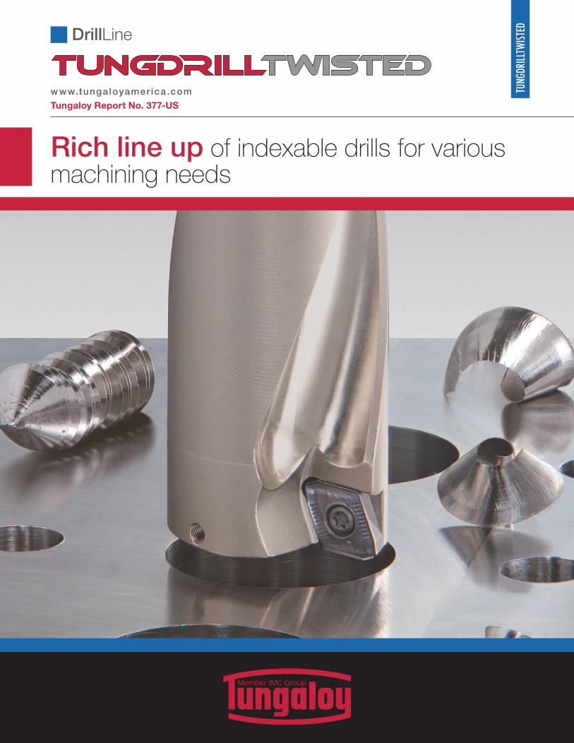
A C C E L E R A T E D M A C H I N I N G
DrillLine
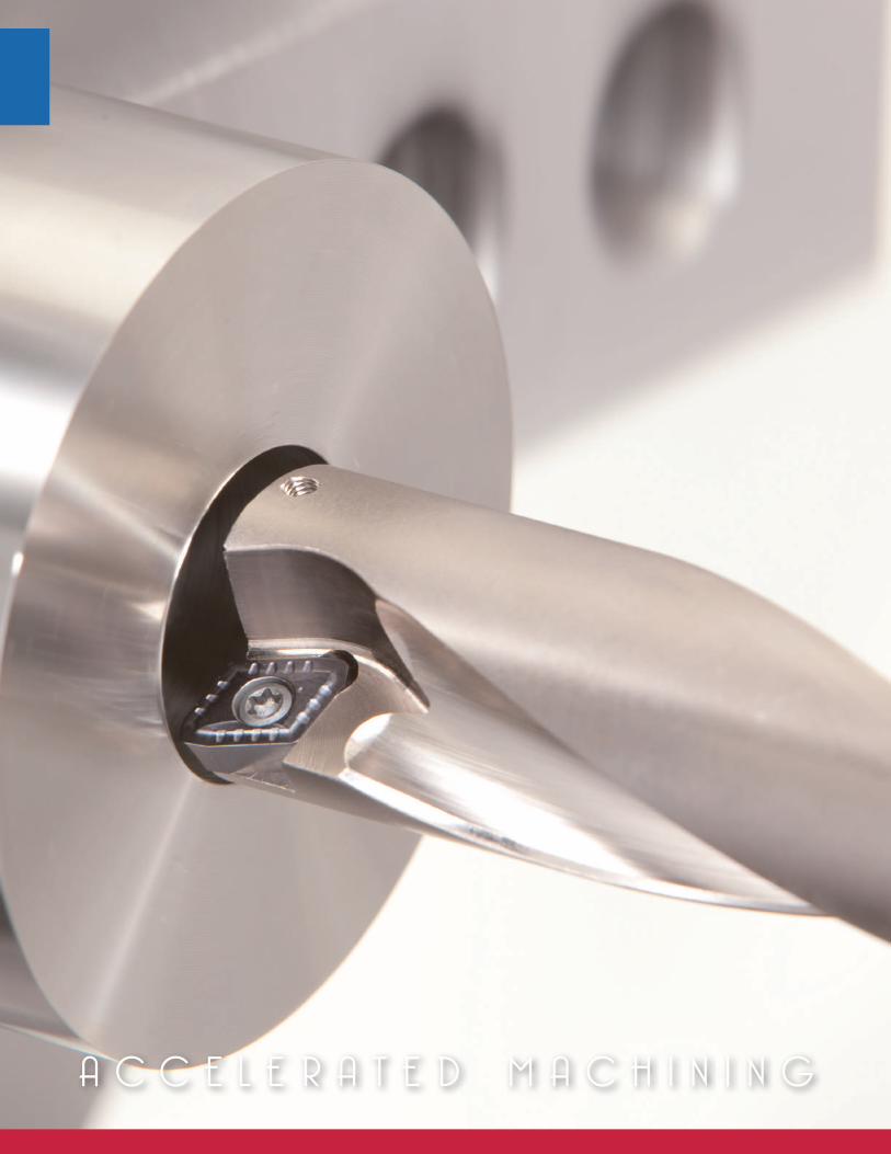
Excellent surface finish and stable chip evacuation due to increased coolant flow with twisted drill body
w w w . t u n g a l o y a m e r i c a . c o m
4 TUNGDRILLTWISTED
25
20
15
10
5
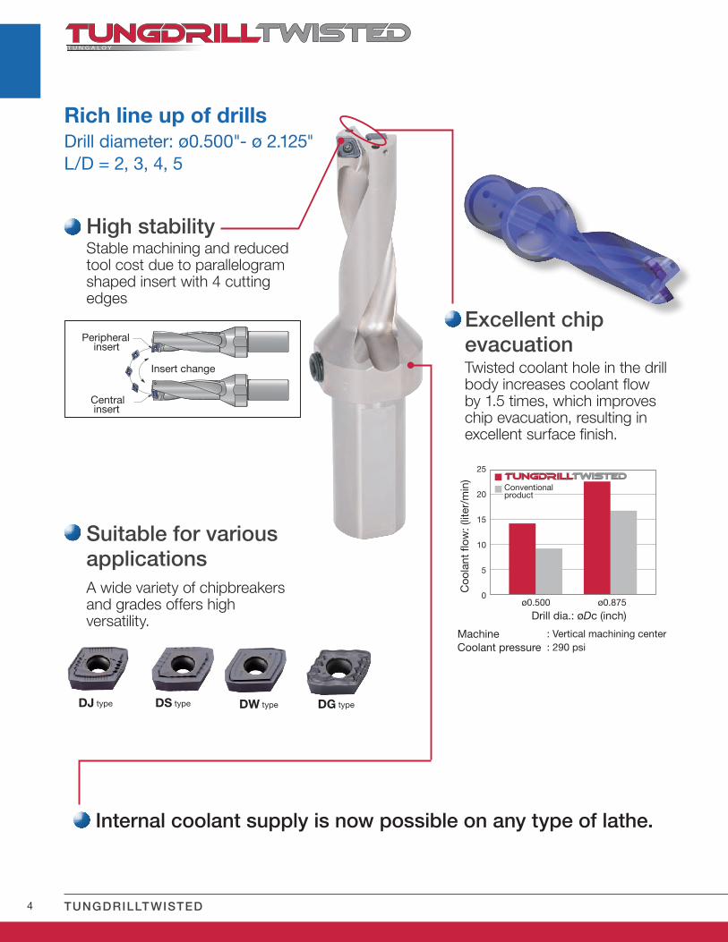
0 ø0.500 ø0.875
Suitable for various applicationsA wide variety of chipbreakers and grades offers high versatility.
: Vertical machining center: 290 psi
Drill dia.: øDc (inch)
Coo
lant
flow
: (lit
er/m
in)
Excellent chip evacuationTwisted coolant hole in the drill body increases coolant flow by 1.5 times, which improves chip evacuation, resulting in excellent surface finish.
High stabilityStable machining and reduced tool cost due to parallelogram shaped insert with 4 cutting edges
Conventionalproduct
MachineCoolant pressure
Peripheral insert Insert change
Central insert
DJ type DS type DW type DG type
Rich line up of drillsDrill diameter: ø0.500"- ø 2.125"L/D = 2, 3, 4, 5
Internal coolant supply is now possible on any type of lathe.
5w w w.t u n g a l oy a m e r i c a .c o m
A CC E L E R A T E D M A C H I N I N G
6 TUNGDRILLTWISTED
0 10 20 30 40 50
25
22
15
10
5
0 10 20 30 40 50
25
22
15
10
5
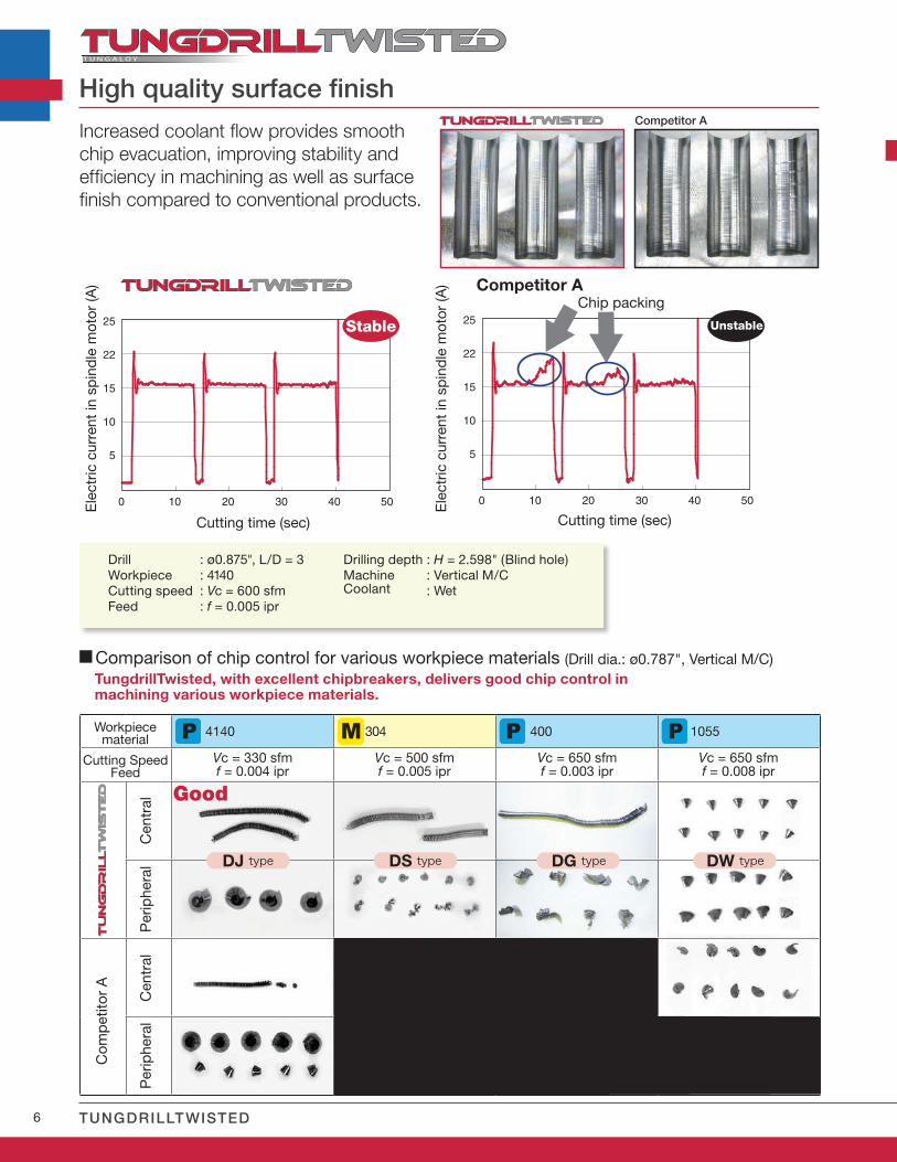
: ø0.875", L/D = 3: 4140: Vc = 600 sfm: f = 0.005 ipr
: H = 2.598" (Blind hole): Vertical M/C: Wet
Cutting time (sec) Cutting time (sec)
Ele
ctric
cur
rent
in s
pin
dle
mot
or (A
)
Ele
ctric
cur
rent
in s
pin
dle
mot
or (A
)
Increased coolant flow provides smooth chip evacuation, improving stability and efficiency in machining as well as surface finish compared to conventional products.
Chip packing
DrillWorkpieceCutting speedFeed
Drilling depthMachineCoolant
High quality surface finish
Stable Unstable
Competitor A
Competitor A
Good
TungdrillTwisted, with excellent chipbreakers, delivers good chip control in machining various workpiece materials.
Cutting SpeedFeed
Unstable
Cen
tral
C
entr
al
Per
iphe
ral
Per
iphe
ral
Com
pet
itor
A
Comparison of chip control for various workpiece materials (Drill dia.: ø0.787", Vertical M/C)
Workpiecematerial
4140 304 400 1055
Vc = 330 sfmf = 0.004 ipr
Vc = 500 sfmf = 0.005 ipr
Vc = 650 sfmf = 0.003 ipr
Vc = 650 sfmf = 0.008 ipr
DJ type DS type DG type DW type
7
0.010
0.008
0.006
0.004
0.002
0
0.012
0.010
0.008
0.006
0.004
0.002
0
0.012
0.010
0.008
0.006
0.004
0.002
0
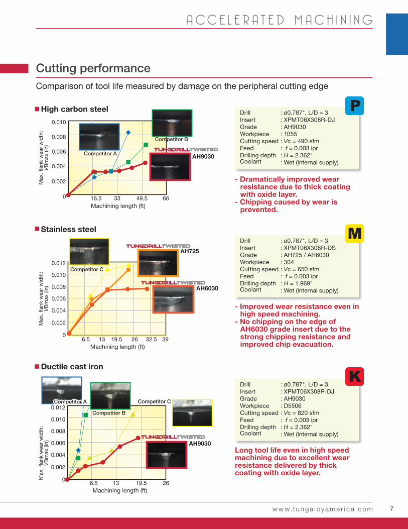
16.5 33 49.5 66
6.5 13 19.5 26 32.5 39
6.5 13 19.5 26
AH9030
AH9030
AH6030
AH725
w w w.t u n g a l oy a m e r i c a .c o m
A CC E L E R A T E D M A C H I N I N G
High carbon steel
Stainless steel
Ductile cast iron
- Dramatically improved wear resistance due to thick coating with oxide layer.
- Chipping caused by wear is prevented.
- Improved wear resistance even in high speed machining.
- No chipping on the edge of AH6030 grade insert due to the strong chipping resistance and improved chip evacuation.
Long tool life even in high speed machining due to excellent wear resistance delivered by thick coating with oxide layer.
Competitor A
Competitor B
Competitor B
Competitor C
Competitor CCompetitor A
Max
. flan
k w
ear
wid
th:
VB
max
(in)
Max
. flan
k w
ear
wid
th:
VB
max
(in)
Max
. flan
k w
ear
wid
th:
VB
max
(in)
: ø0.787", L/D = 3: XPMT06X308R-DJ: AH9030: 1055: Vc = 490 sfm: f = 0.003 ipr: H = 2.362": Wet (Internal supply)
: ø0.787", L/D = 3: XPMT06X308R-DS: AH725 / AH6030: 304: Vc = 650 sfm: f = 0.003 ipr: H = 1.969": Wet (Internal supply)
: ø0.787", L/D = 3: XPMT06X308R-DJ: AH9030: D5506: Vc = 820 sfm: f = 0.003 ipr: H = 2.362": Wet (Internal supply)
DrillInsertGradeWorkpieceCutting speedFeedDrilling depthCoolant
DrillInsertGradeWorkpieceCutting speedFeedDrilling depthCoolant
DrillInsertGradeWorkpieceCutting speedFeedDrilling depthCoolant
Machining length (ft)
Machining length (ft)
Machining length (ft)
Cutting performanceComparison of tool life measured by damage on the peripheral cutting edge
8 TUNGDRILLTWISTED
AH725 T1115
AH9030AH6030
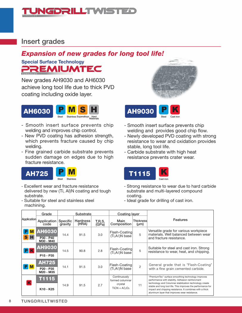
- Strong resistance to wear due to hard carbide substrate and multi-layered compound coating.
- Ideal grade for drilling of cast iron.
Insert grades
- Excellent wear and fracture resistance delivered by new (Ti, Al)N coating and tough substrate.
- Suitable for steel and stainless steel machining.
- Smooth insert surface prevents chip welding and improves chip control.
- New PVD coating has adhesion strength, which prevents fracture caused by chip welding.
- Fine grained carbide substrate prevents sudden damage on edges due to high fracture resistance.
- Smooth insert surface prevents chip welding and provides good chip flow.
- Newly developed PVD coating with strong resistance to wear and oxidation provides stable, long tool life.
- Carbide substrate with high heat resistance prevents crater wear.
Expansion of new grades for long tool life!
New grades AH9030 and AH6030 achieve long tool life due to thick PVD coating including oxide layer.
AH603014.4 91.5 3.0 5
P30 - P40M30 - M40
AH903014.5 90.8 2.8 5
P15 - P35
AH72514.1 91.5 3.0 2
General grade that is "Flash-Coating" with a fine grain cemented carbide.P20 - P35
M20 - M35
T111514.9 91.5 2.7 11
K10 - K25
Application FeaturesApplicationcode
Specific gravity
MainComposition
Hardness(HRA)
T.R.S.(GPa)
Thickness(μm)
Suitable for steel and cast iron. Strong resistance to wear, heat, and chipping.
Versatile grade for various workpiece materials. Well balanced between wear and fracture resistance.
Flash-Coating(Ti,Aℓ)N base
Flash-Coating(Ti,Aℓ)N base
Grade Substrate Coating layer
Special Surface Technology
Stainless
Stainless
Superalloys SteelSteel
Steel
Cast iron
Cast iron
Hard Materials
Flash-Coating(Ti,Aℓ)N base
Continuously formed columnar
crystal
TiCN + Aℓ2O3
"PremiumTec" surface smoothing technology improves performance with stability. Adhesion reinforcment technology and Columnar stabilization technology create stable and long tool life. This improves the performance for impact and chipping resistance. It combines with a thick aluminum layer that improves wear resistance.
9w w w.t u n g a l oy a m e r i c a .c o m
A CC E L E R A T E D M A C H I N I N G
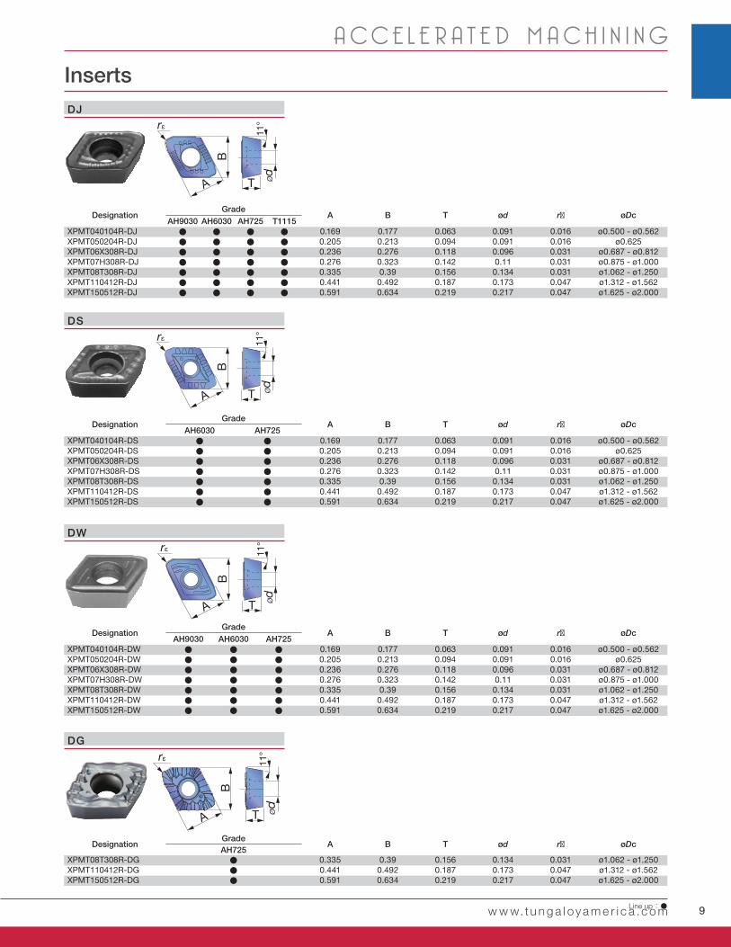
Inserts
rε
A
B
T
11°
Ød
rε
A
B
T
11°
Ød
A
B
T
11°
Ød
rε
rε
A
B
T
11°
Ød
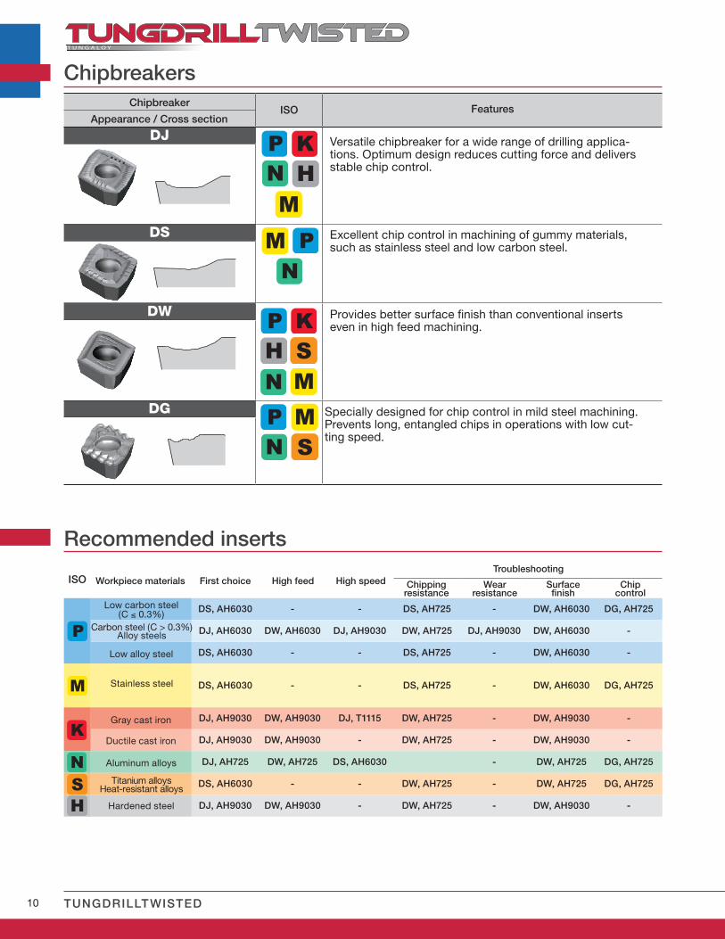
DJ
DS
DW
DG
DesignationGrade
A B T ød rε øDcAH9030 AH6030 AH725 T1115
XPMT040104R-DJ ● ● ● ● 0.169 0.177 0.063 0.091 0.016 ø0.500 - ø0.562XPMT050204R-DJ ● ● ● ● 0.205 0.213 0.094 0.091 0.016 ø0.625XPMT06X308R-DJ ● ● ● ● 0.236 0.276 0.118 0.096 0.031 ø0.687 - ø0.812XPMT07H308R-DJ ● ● ● ● 0.276 0.323 0.142 0.11 0.031 ø0.875 - ø1.000XPMT08T308R-DJ ● ● ● ● 0.335 0.39 0.156 0.134 0.031 ø1.062 - ø1.250XPMT110412R-DJ ● ● ● ● 0.441 0.492 0.187 0.173 0.047 ø1.312 - ø1.562XPMT150512R-DJ ● ● ● ● 0.591 0.634 0.219 0.217 0.047 ø1.625 - ø2.000
DesignationGrade
A B T ød rε øDcAH6030 AH725
XPMT040104R-DS ● ● 0.169 0.177 0.063 0.091 0.016 ø0.500 - ø0.562XPMT050204R-DS ● ● 0.205 0.213 0.094 0.091 0.016 ø0.625XPMT06X308R-DS ● ● 0.236 0.276 0.118 0.096 0.031 ø0.687 - ø0.812XPMT07H308R-DS ● ● 0.276 0.323 0.142 0.11 0.031 ø0.875 - ø1.000XPMT08T308R-DS ● ● 0.335 0.39 0.156 0.134 0.031 ø1.062 - ø1.250XPMT110412R-DS ● ● 0.441 0.492 0.187 0.173 0.047 ø1.312 - ø1.562XPMT150512R-DS ● ● 0.591 0.634 0.219 0.217 0.047 ø1.625 - ø2.000
DesignationGrade
A B T ød rε øDcAH9030 AH6030 AH725
XPMT040104R-DW ● ● ● 0.169 0.177 0.063 0.091 0.016 ø0.500 - ø0.562XPMT050204R-DW ● ● ● 0.205 0.213 0.094 0.091 0.016 ø0.625XPMT06X308R-DW ● ● ● 0.236 0.276 0.118 0.096 0.031 ø0.687 - ø0.812XPMT07H308R-DW ● ● ● 0.276 0.323 0.142 0.11 0.031 ø0.875 - ø1.000XPMT08T308R-DW ● ● ● 0.335 0.39 0.156 0.134 0.031 ø1.062 - ø1.250XPMT110412R-DW ● ● ● 0.441 0.492 0.187 0.173 0.047 ø1.312 - ø1.562XPMT150512R-DW ● ● ● 0.591 0.634 0.219 0.217 0.047 ø1.625 - ø2.000
DesignationGrade
A B T ød rε øDcAH725
XPMT08T308R-DG ● 0.335 0.39 0.156 0.134 0.031 ø1.062 - ø1.250XPMT110412R-DG ● 0.441 0.492 0.187 0.173 0.047 ø1.312 - ø1.562XPMT150512R-DG ● 0.591 0.634 0.219 0.217 0.047 ø1.625 - ø2.000
Line up:●
10 TUNGDRILLTWISTED
ISO
DS, AH6030 - - DS, AH725 - DW, AH6030 DG, AH725
DJ, AH6030 DW, AH6030 DJ, AH9030 DW, AH725 DJ, AH9030 DW, AH6030 -
DS, AH6030 - - DS, AH725 - DW, AH6030 -
DS, AH6030 - - DS, AH725 - DW, AH6030 DG, AH725
DJ, AH9030 DW, AH9030 DJ, T1115 DW, AH725 - DW, AH9030 -
DJ, AH9030 DW, AH9030 - DW, AH725 - DW, AH9030 -
DJ, AH725 DW, AH725 DS, AH6030 - DW, AH725 DG, AH725
DS, AH6030 - - DW, AH725 - DW, AH725 DG, AH725
DJ, AH9030 DW, AH9030 - DW, AH725 - DW, AH9030 -
ISO
DJ
DS
DW
DG
Recommended inserts
Workpiece materials First choice High feed High speed Chippingresistance
Wearresistance
Surfacefinish
Chipcontrol
Troubleshooting
Low carbon steel (C ≤ 0.3%)
Low alloy steel
Carbon steel (C > 0.3%)Alloy steels
Stainless steel
Titanium alloysHeat-resistant alloys
Gray cast iron
Ductile cast iron
Aluminum alloys
Hardened steel
Appearance / Cross section
ChipbreakerFeatures
Chipbreakers
Versatile chipbreaker for a wide range of drilling applica-tions. Optimum design reduces cutting force and delivers stable chip control.
Excellent chip control in machining of gummy materials, such as stainless steel and low carbon steel.
Provides better surface finish than conventional inserts even in high feed machining.
Specially designed for chip control in mild steel machining.Prevents long, entangled chips in operations with low cut-ting speed.
11
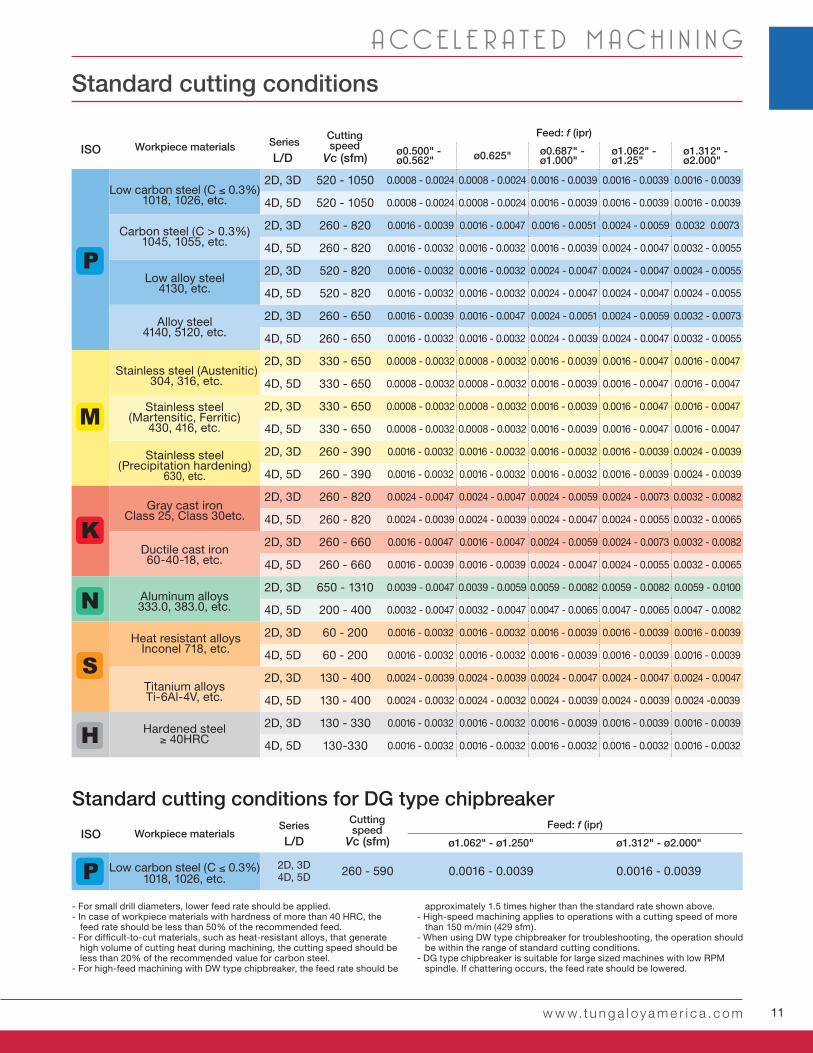
L/D Vc (sfm)ø0.500" - ø0.562" ø0.625" ø0.687" -
ø1.000"ø1.062" - ø1.25"
ø1.312" - ø2.000"
2D, 3D 520 - 1050 0.0008 - 0.0024 0.0008 - 0.0024 0.0016 - 0.0039 0.0016 - 0.0039 0.0016 - 0.0039
4D, 5D 520 - 1050 0.0008 - 0.0024 0.0008 - 0.0024 0.0016 - 0.0039 0.0016 - 0.0039 0.0016 - 0.0039
2D, 3D 260 - 820 0.0016 - 0.0039 0.0016 - 0.0047 0.0016 - 0.0051 0.0024 - 0.0059 0.0032 0.0073
4D, 5D 260 - 820 0.0016 - 0.0032 0.0016 - 0.0032 0.0016 - 0.0039 0.0024 - 0.0047 0.0032 - 0.0055
2D, 3D 520 - 820 0.0016 - 0.0032 0.0016 - 0.0032 0.0024 - 0.0047 0.0024 - 0.0047 0.0024 - 0.0055
4D, 5D 520 - 820 0.0016 - 0.0032 0.0016 - 0.0032 0.0024 - 0.0047 0.0024 - 0.0047 0.0024 - 0.0055
2D, 3D 260 - 650 0.0016 - 0.0039 0.0016 - 0.0047 0.0024 - 0.0051 0.0024 - 0.0059 0.0032 - 0.0073
4D, 5D 260 - 650 0.0016 - 0.0032 0.0016 - 0.0032 0.0024 - 0.0039 0.0024 - 0.0047 0.0032 - 0.0055
2D, 3D 330 - 650 0.0008 - 0.0032 0.0008 - 0.0032 0.0016 - 0.0039 0.0016 - 0.0047 0.0016 - 0.0047
4D, 5D 330 - 650 0.0008 - 0.0032 0.0008 - 0.0032 0.0016 - 0.0039 0.0016 - 0.0047 0.0016 - 0.0047
2D, 3D 330 - 650 0.0008 - 0.0032 0.0008 - 0.0032 0.0016 - 0.0039 0.0016 - 0.0047 0.0016 - 0.0047
4D, 5D 330 - 650 0.0008 - 0.0032 0.0008 - 0.0032 0.0016 - 0.0039 0.0016 - 0.0047 0.0016 - 0.0047
2D, 3D 260 - 390 0.0016 - 0.0032 0.0016 - 0.0032 0.0016 - 0.0032 0.0016 - 0.0039 0.0024 - 0.0039
4D, 5D 260 - 390 0.0016 - 0.0032 0.0016 - 0.0032 0.0016 - 0.0032 0.0016 - 0.0039 0.0024 - 0.0039
2D, 3D 260 - 820 0.0024 - 0.0047 0.0024 - 0.0047 0.0024 - 0.0059 0.0024 - 0.0073 0.0032 - 0.0082
4D, 5D 260 - 820 0.0024 - 0.0039 0.0024 - 0.0039 0.0024 - 0.0047 0.0024 - 0.0055 0.0032 - 0.0065
2D, 3D 260 - 660 0.0016 - 0.0047 0.0016 - 0.0047 0.0024 - 0.0059 0.0024 - 0.0073 0.0032 - 0.0082
4D, 5D 260 - 660 0.0016 - 0.0039 0.0016 - 0.0039 0.0024 - 0.0047 0.0024 - 0.0055 0.0032 - 0.0065
2D, 3D 650 - 1310 0.0039 - 0.0047 0.0039 - 0.0059 0.0059 - 0.0082 0.0059 - 0.0082 0.0059 - 0.0100
4D, 5D 200 - 400 0.0032 - 0.0047 0.0032 - 0.0047 0.0047 - 0.0065 0.0047 - 0.0065 0.0047 - 0.0082
2D, 3D 60 - 200 0.0016 - 0.0032 0.0016 - 0.0032 0.0016 - 0.0039 0.0016 - 0.0039 0.0016 - 0.0039
4D, 5D 60 - 200 0.0016 - 0.0032 0.0016 - 0.0032 0.0016 - 0.0039 0.0016 - 0.0039 0.0016 - 0.0039
2D, 3D 130 - 400 0.0024 - 0.0039 0.0024 - 0.0039 0.0024 - 0.0047 0.0024 - 0.0047 0.0024 - 0.0047
4D, 5D 130 - 400 0.0024 - 0.0032 0.0024 - 0.0032 0.0024 - 0.0039 0.0024 - 0.0039 0.0024 -0.0039
2D, 3D 130 - 330 0.0016 - 0.0032 0.0016 - 0.0032 0.0016 - 0.0039 0.0016 - 0.0039 0.0016 - 0.0039
4D, 5D 130-330 0.0016 - 0.0032 0.0016 - 0.0032 0.0016 - 0.0032 0.0016 - 0.0032 0.0016 - 0.0032
L/D Vc (sfm) ø1.062" - ø1.250" ø1.312" - ø2.000"
2D, 3D4D, 5D 260 - 590 0.0016 - 0.0039 0.0016 - 0.0039
ISO
ISO
w w w.t u n g a l oy a m e r i c a .c o m
A CC E L E R A T E D M A C H I N I N G
- For small drill diameters, lower feed rate should be applied. - In case of workpiece materials with hardness of more than 40 HRC, the
feed rate should be less than 50% of the recommended feed. - For difficult-to-cut materials, such as heat-resistant alloys, that generate
high volume of cutting heat during machining, the cutting speed should be less than 20% of the recommended value for carbon steel.
- For high-feed machining with DW type chipbreaker, the feed rate should be
approximately 1.5 times higher than the standard rate shown above. - High-speed machining applies to operations with a cutting speed of more
than 150 m/min (429 sfm).- When using DW type chipbreaker for troubleshooting, the operation should
be within the range of standard cutting conditions.- DG type chipbreaker is suitable for large sized machines with low RPM
spindle. If chattering occurs, the feed rate should be lowered.
Workpiece materialsFeed: f (ipr)Cutting
speedSeries
Workpiece materialsFeed: f (ipr)Cutting
speedSeries
Low carbon steel (C ≤ 0.3%)1018, 1026, etc.
Standard cutting conditions for DG type chipbreaker
Low carbon steel (C ≤ 0.3%) 1018, 1026, etc.
Carbon steel (C > 0.3%)1045, 1055, etc.
Low alloy steel4130, etc.
Alloy steel4140, 5120, etc.
Stainless steel (Austenitic)304, 316, etc.
Stainless steel (Martensitic, Ferritic)
430, 416, etc.
Stainless steel (Precipitation hardening)
630, etc.
Gray cast ironClass 25, Class 30etc.
Ductile cast iron60-40-18, etc.
Aluminum alloys333.0, 383.0, etc.
Heat resistant alloysInconel 718, etc.
Titanium alloysTi-6Al-4V, etc.
Hardened steel≥ 40HRC
Standard cutting conditions
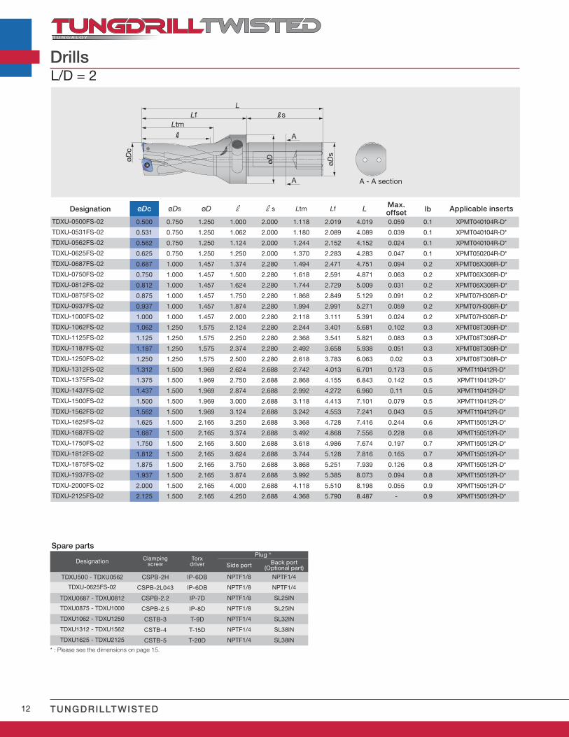
12 TUNGDRILLTWISTED
øDc
øD øDs
LtmLf
R
RsL
A
A A - A section
L/D = 2
Designation øDc øDs øD r rs Ltm Lf L Max.offset lb Applicable inserts
TDXU-0500FS-02 0.500 0.750 1.250 1.000 2.000 1.118 2.019 4.019 0.059 0.1 XPMT040104R-D*
TDXU-0531FS-02 0.531 0.750 1.250 1.062 2.000 1.180 2.089 4.089 0.039 0.1 XPMT040104R-D*
TDXU-0562FS-02 0.562 0.750 1.250 1.124 2.000 1.244 2.152 4.152 0.024 0.1 XPMT040104R-D*
TDXU-0625FS-02 0.625 0.750 1.250 1.250 2.000 1.370 2.283 4.283 0.047 0.1 XPMT050204R-D*
TDXU-0687FS-02 0.687 1.000 1.457 1.374 2.280 1.494 2.471 4.751 0.094 0.2 XPMT06X308R-D*
TDXU-0750FS-02 0.750 1.000 1.457 1.500 2.280 1.618 2.591 4.871 0.063 0.2 XPMT06X308R-D*
TDXU-0812FS-02 0.812 1.000 1.457 1.624 2.280 1.744 2.729 5.009 0.031 0.2 XPMT06X308R-D*
TDXU-0875FS-02 0.875 1.000 1.457 1.750 2.280 1.868 2.849 5.129 0.091 0.2 XPMT07H308R-D*
TDXU-0937FS-02 0.937 1.000 1.457 1.874 2.280 1.994 2.991 5.271 0.059 0.2 XPMT07H308R-D*
TDXU-1000FS-02 1.000 1.000 1.457 2.000 2.280 2.118 3.111 5.391 0.024 0.2 XPMT07H308R-D*
TDXU-1062FS-02 1.062 1.250 1.575 2.124 2.280 2.244 3.401 5.681 0.102 0.3 XPMT08T308R-D*
TDXU-1125FS-02 1.125 1.250 1.575 2.250 2.280 2.368 3.541 5.821 0.083 0.3 XPMT08T308R-D*
TDXU-1187FS-02 1.187 1.250 1.575 2.374 2.280 2.492 3.658 5.938 0.051 0.3 XPMT08T308R-D*
TDXU-1250FS-02 1.250 1.250 1.575 2.500 2.280 2.618 3.783 6.063 0.02 0.3 XPMT08T308R-D*
TDXU-1312FS-02 1.312 1.500 1.969 2.624 2.688 2.742 4.013 6.701 0.173 0.5 XPMT110412R-D*
TDXU-1375FS-02 1.375 1.500 1.969 2.750 2.688 2.868 4.155 6.843 0.142 0.5 XPMT110412R-D*
TDXU-1437FS-02 1.437 1.500 1.969 2.874 2.688 2.992 4.272 6.960 0.11 0.5 XPMT110412R-D*
TDXU-1500FS-02 1.500 1.500 1.969 3.000 2.688 3.118 4.413 7.101 0.079 0.5 XPMT110412R-D*
TDXU-1562FS-02 1.562 1.500 1.969 3.124 2.688 3.242 4.553 7.241 0.043 0.5 XPMT110412R-D*
TDXU-1625FS-02 1.625 1.500 2.165 3.250 2.688 3.368 4.728 7.416 0.244 0.6 XPMT150512R-D*
TDXU-1687FS-02 1.687 1.500 2.165 3.374 2.688 3.492 4.868 7.556 0.228 0.6 XPMT150512R-D*
TDXU-1750FS-02 1.750 1.500 2.165 3.500 2.688 3.618 4.986 7.674 0.197 0.7 XPMT150512R-D*
TDXU-1812FS-02 1.812 1.500 2.165 3.624 2.688 3.744 5.128 7.816 0.165 0.7 XPMT150512R-D*
TDXU-1875FS-02 1.875 1.500 2.165 3.750 2.688 3.868 5.251 7.939 0.126 0.8 XPMT150512R-D*
TDXU-1937FS-02 1.937 1.500 2.165 3.874 2.688 3.992 5.385 8.073 0.094 0.8 XPMT150512R-D*
TDXU-2000FS-02 2.000 1.500 2.165 4.000 2.688 4.118 5.510 8.198 0.055 0.9 XPMT150512R-D*
TDXU-2125FS-02 2.125 1.500 2.165 4.250 2.688 4.368 5.790 8.487 - 0.9 XPMT150512R-D*
Drills
Spare parts
Designation Clampingscrew
Torxdriver
Plug *
Side port Back port(Optional part)
TDXU500 - TDXU0562 CSPB-2H IP-6DB NPTF1/8 NPTF1/4
TDXU-0625FS-02 CSPB-2L043 IP-6DB NPTF1/8 NPTF1/4
TDXU0687 - TDXU0812 CSPB-2.2 IP-7D NPTF1/8 SL25IN
TDXU0875 - TDXU1000 CSPB-2.5 IP-8D NPTF1/8 SL25IN
TDXU1062 - TDXU1250 CSTB-3 T-9D NPTF1/4 SL32IN
TDXU1312 - TDXU1562 CSTB-4 T-15D NPTF1/4 SL38IN
TDXU1625 - TDXU2125 CSTB-5 T-20D NPTF1/4 SL38IN
* : Please see the dimensions on page 15.
13
øDc
øDs
øD
R
Ltm
LLf Rs
A
A A - A section
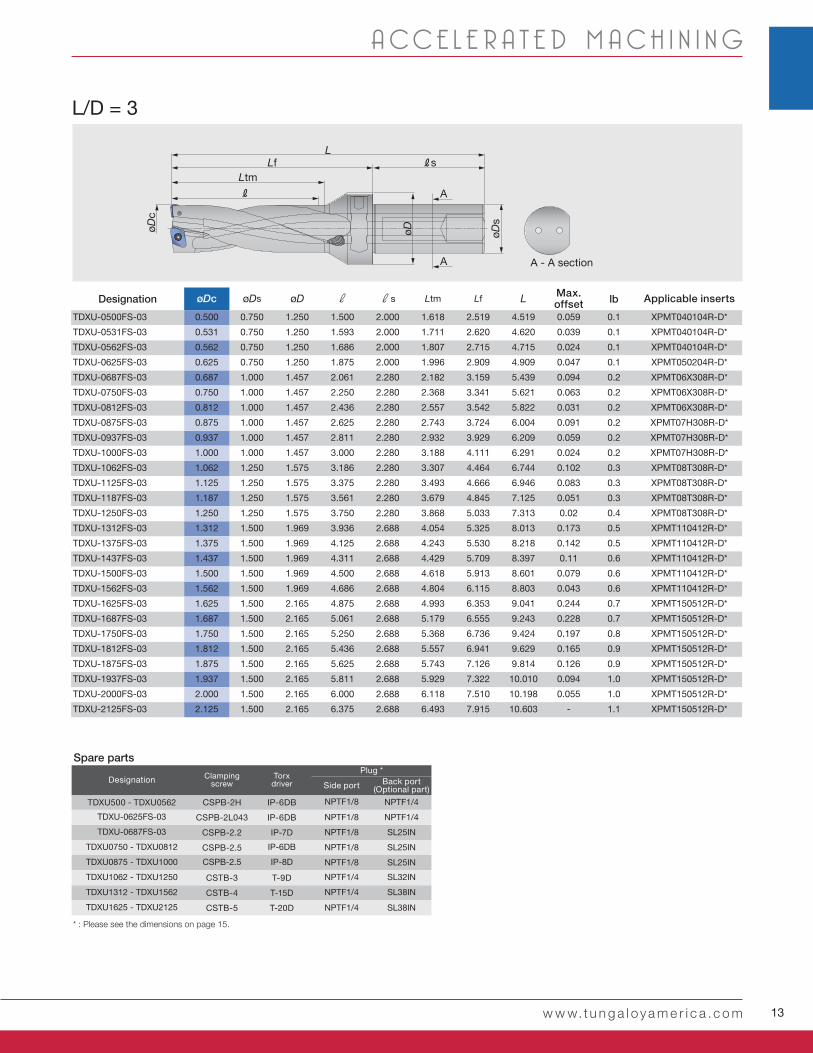
L/D = 3
Designation øDc øDs øD r rs Ltm Lf L Max.offset lb Applicable inserts
TDXU-0500FS-03 0.500 0.750 1.250 1.500 2.000 1.618 2.519 4.519 0.059 0.1 XPMT040104R-D*
TDXU-0531FS-03 0.531 0.750 1.250 1.593 2.000 1.711 2.620 4.620 0.039 0.1 XPMT040104R-D*
TDXU-0562FS-03 0.562 0.750 1.250 1.686 2.000 1.807 2.715 4.715 0.024 0.1 XPMT040104R-D*
TDXU-0625FS-03 0.625 0.750 1.250 1.875 2.000 1.996 2.909 4.909 0.047 0.1 XPMT050204R-D*
TDXU-0687FS-03 0.687 1.000 1.457 2.061 2.280 2.182 3.159 5.439 0.094 0.2 XPMT06X308R-D*
TDXU-0750FS-03 0.750 1.000 1.457 2.250 2.280 2.368 3.341 5.621 0.063 0.2 XPMT06X308R-D*
TDXU-0812FS-03 0.812 1.000 1.457 2.436 2.280 2.557 3.542 5.822 0.031 0.2 XPMT06X308R-D*
TDXU-0875FS-03 0.875 1.000 1.457 2.625 2.280 2.743 3.724 6.004 0.091 0.2 XPMT07H308R-D*
TDXU-0937FS-03 0.937 1.000 1.457 2.811 2.280 2.932 3.929 6.209 0.059 0.2 XPMT07H308R-D*
TDXU-1000FS-03 1.000 1.000 1.457 3.000 2.280 3.188 4.111 6.291 0.024 0.2 XPMT07H308R-D*
TDXU-1062FS-03 1.062 1.250 1.575 3.186 2.280 3.307 4.464 6.744 0.102 0.3 XPMT08T308R-D*
TDXU-1125FS-03 1.125 1.250 1.575 3.375 2.280 3.493 4.666 6.946 0.083 0.3 XPMT08T308R-D*
TDXU-1187FS-03 1.187 1.250 1.575 3.561 2.280 3.679 4.845 7.125 0.051 0.3 XPMT08T308R-D*
TDXU-1250FS-03 1.250 1.250 1.575 3.750 2.280 3.868 5.033 7.313 0.02 0.4 XPMT08T308R-D*
TDXU-1312FS-03 1.312 1.500 1.969 3.936 2.688 4.054 5.325 8.013 0.173 0.5 XPMT110412R-D*
TDXU-1375FS-03 1.375 1.500 1.969 4.125 2.688 4.243 5.530 8.218 0.142 0.5 XPMT110412R-D*
TDXU-1437FS-03 1.437 1.500 1.969 4.311 2.688 4.429 5.709 8.397 0.11 0.6 XPMT110412R-D*
TDXU-1500FS-03 1.500 1.500 1.969 4.500 2.688 4.618 5.913 8.601 0.079 0.6 XPMT110412R-D*
TDXU-1562FS-03 1.562 1.500 1.969 4.686 2.688 4.804 6.115 8.803 0.043 0.6 XPMT110412R-D*
TDXU-1625FS-03 1.625 1.500 2.165 4.875 2.688 4.993 6.353 9.041 0.244 0.7 XPMT150512R-D*
TDXU-1687FS-03 1.687 1.500 2.165 5.061 2.688 5.179 6.555 9.243 0.228 0.7 XPMT150512R-D*
TDXU-1750FS-03 1.750 1.500 2.165 5.250 2.688 5.368 6.736 9.424 0.197 0.8 XPMT150512R-D*
TDXU-1812FS-03 1.812 1.500 2.165 5.436 2.688 5.557 6.941 9.629 0.165 0.9 XPMT150512R-D*
TDXU-1875FS-03 1.875 1.500 2.165 5.625 2.688 5.743 7.126 9.814 0.126 0.9 XPMT150512R-D*
TDXU-1937FS-03 1.937 1.500 2.165 5.811 2.688 5.929 7.322 10.010 0.094 1.0 XPMT150512R-D*
TDXU-2000FS-03 2.000 1.500 2.165 6.000 2.688 6.118 7.510 10.198 0.055 1.0 XPMT150512R-D*
TDXU-2125FS-03 2.125 1.500 2.165 6.375 2.688 6.493 7.915 10.603 - 1.1 XPMT150512R-D*
w w w.t u n g a l oy a m e r i c a .c o m
A CC E L E R A T E D M A C H I N I N G
Spare parts
Designation Clampingscrew
Torxdriver
Plug *
Side port Back port(Optional part)
TDXU500 - TDXU0562 CSPB-2H IP-6DB NPTF1/8 NPTF1/4
TDXU-0625FS-03 CSPB-2L043 IP-6DB NPTF1/8 NPTF1/4
TDXU-0687FS-03 CSPB-2.2 IP-7D NPTF1/8 SL25IN
TDXU0750 - TDXU0812 CSPB-2.5 IP-6DB NPTF1/8 SL25IN
TDXU0875 - TDXU1000 CSPB-2.5 IP-8D NPTF1/8 SL25IN
TDXU1062 - TDXU1250 CSTB-3 T-9D NPTF1/4 SL32IN
TDXU1312 - TDXU1562 CSTB-4 T-15D NPTF1/4 SL38IN
TDXU1625 - TDXU2125 CSTB-5 T-20D NPTF1/4 SL38IN
* : Please see the dimensions on page 15.
14 TUNGDRILLTWISTED
øDc
øDs
øD
R
Ltm
LLf Rs
A
A A - A section
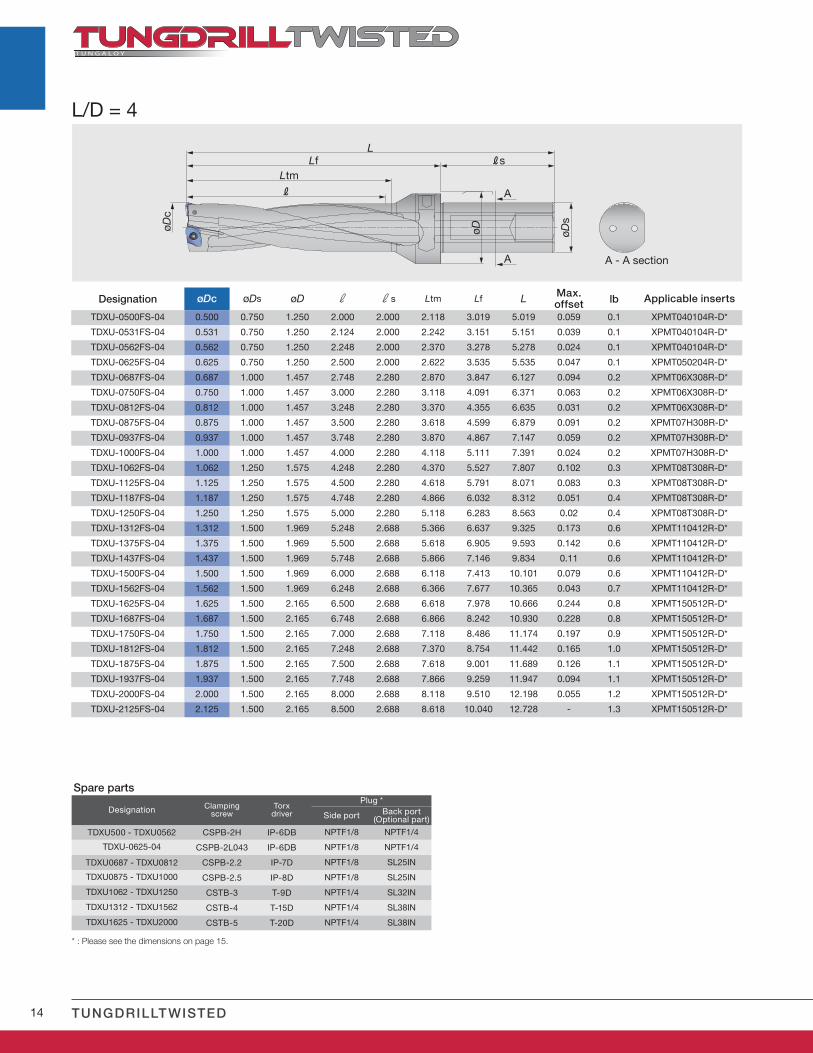
L/D = 4
Designation øDc øDs øD r rs Ltm Lf L Max.offset lb Applicable inserts
TDXU-0500FS-04 0.500 0.750 1.250 2.000 2.000 2.118 3.019 5.019 0.059 0.1 XPMT040104R-D*
TDXU-0531FS-04 0.531 0.750 1.250 2.124 2.000 2.242 3.151 5.151 0.039 0.1 XPMT040104R-D*
TDXU-0562FS-04 0.562 0.750 1.250 2.248 2.000 2.370 3.278 5.278 0.024 0.1 XPMT040104R-D*
TDXU-0625FS-04 0.625 0.750 1.250 2.500 2.000 2.622 3.535 5.535 0.047 0.1 XPMT050204R-D*
TDXU-0687FS-04 0.687 1.000 1.457 2.748 2.280 2.870 3.847 6.127 0.094 0.2 XPMT06X308R-D*
TDXU-0750FS-04 0.750 1.000 1.457 3.000 2.280 3.118 4.091 6.371 0.063 0.2 XPMT06X308R-D*
TDXU-0812FS-04 0.812 1.000 1.457 3.248 2.280 3.370 4.355 6.635 0.031 0.2 XPMT06X308R-D*
TDXU-0875FS-04 0.875 1.000 1.457 3.500 2.280 3.618 4.599 6.879 0.091 0.2 XPMT07H308R-D*
TDXU-0937FS-04 0.937 1.000 1.457 3.748 2.280 3.870 4.867 7.147 0.059 0.2 XPMT07H308R-D*
TDXU-1000FS-04 1.000 1.000 1.457 4.000 2.280 4.118 5.111 7.391 0.024 0.2 XPMT07H308R-D*
TDXU-1062FS-04 1.062 1.250 1.575 4.248 2.280 4.370 5.527 7.807 0.102 0.3 XPMT08T308R-D*
TDXU-1125FS-04 1.125 1.250 1.575 4.500 2.280 4.618 5.791 8.071 0.083 0.3 XPMT08T308R-D*
TDXU-1187FS-04 1.187 1.250 1.575 4.748 2.280 4.866 6.032 8.312 0.051 0.4 XPMT08T308R-D*
TDXU-1250FS-04 1.250 1.250 1.575 5.000 2.280 5.118 6.283 8.563 0.02 0.4 XPMT08T308R-D*
TDXU-1312FS-04 1.312 1.500 1.969 5.248 2.688 5.366 6.637 9.325 0.173 0.6 XPMT110412R-D*
TDXU-1375FS-04 1.375 1.500 1.969 5.500 2.688 5.618 6.905 9.593 0.142 0.6 XPMT110412R-D*
TDXU-1437FS-04 1.437 1.500 1.969 5.748 2.688 5.866 7.146 9.834 0.11 0.6 XPMT110412R-D*
TDXU-1500FS-04 1.500 1.500 1.969 6.000 2.688 6.118 7.413 10.101 0.079 0.6 XPMT110412R-D*
TDXU-1562FS-04 1.562 1.500 1.969 6.248 2.688 6.366 7.677 10.365 0.043 0.7 XPMT110412R-D*
TDXU-1625FS-04 1.625 1.500 2.165 6.500 2.688 6.618 7.978 10.666 0.244 0.8 XPMT150512R-D*
TDXU-1687FS-04 1.687 1.500 2.165 6.748 2.688 6.866 8.242 10.930 0.228 0.8 XPMT150512R-D*
TDXU-1750FS-04 1.750 1.500 2.165 7.000 2.688 7.118 8.486 11.174 0.197 0.9 XPMT150512R-D*
TDXU-1812FS-04 1.812 1.500 2.165 7.248 2.688 7.370 8.754 11.442 0.165 1.0 XPMT150512R-D*
TDXU-1875FS-04 1.875 1.500 2.165 7.500 2.688 7.618 9.001 11.689 0.126 1.1 XPMT150512R-D*
TDXU-1937FS-04 1.937 1.500 2.165 7.748 2.688 7.866 9.259 11.947 0.094 1.1 XPMT150512R-D*
TDXU-2000FS-04 2.000 1.500 2.165 8.000 2.688 8.118 9.510 12.198 0.055 1.2 XPMT150512R-D*
TDXU-2125FS-04 2.125 1.500 2.165 8.500 2.688 8.618 10.040 12.728 - 1.3 XPMT150512R-D*
Spare parts
Designation Clampingscrew
Torxdriver
Plug *
Side port Back port(Optional part)
TDXU500 - TDXU0562 CSPB-2H IP-6DB NPTF1/8 NPTF1/4
TDXU-0625-04 CSPB-2L043 IP-6DB NPTF1/8 NPTF1/4
TDXU0687 - TDXU0812 CSPB-2.2 IP-7D NPTF1/8 SL25IN
TDXU0875 - TDXU1000 CSPB-2.5 IP-8D NPTF1/8 SL25IN
TDXU1062 - TDXU1250 CSTB-3 T-9D NPTF1/4 SL32IN
TDXU1312 - TDXU1562 CSTB-4 T-15D NPTF1/4 SL38IN
TDXU1625 - TDXU2000 CSTB-5 T-20D NPTF1/4 SL38IN
* : Please see the dimensions on page 15.
15
øD
R
Ltm
LLf Rs
øDc
øDs
A
A A - A section
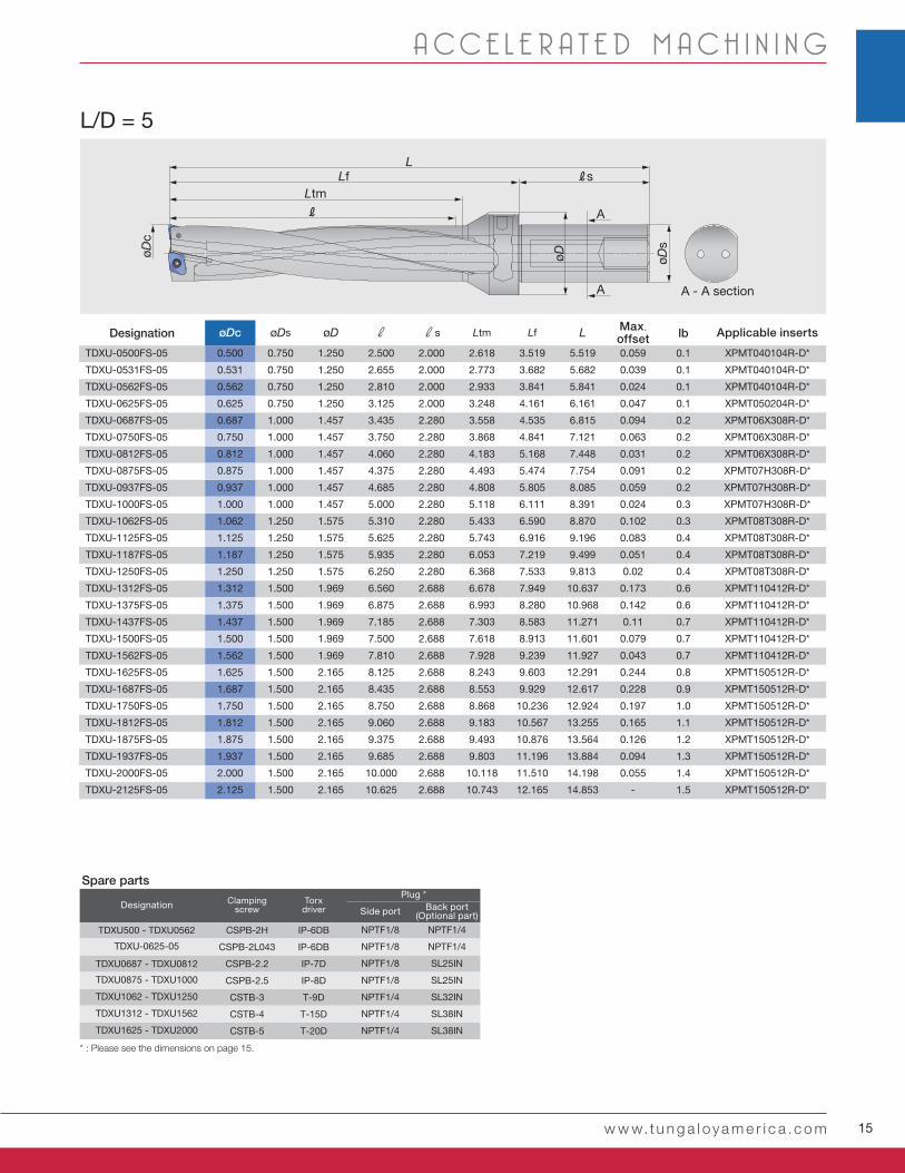
L/D = 5
Designation øDc øDs øD r rs Ltm Lf L Max.offset lb Applicable inserts
TDXU-0500FS-05 0.500 0.750 1.250 2.500 2.000 2.618 3.519 5.519 0.059 0.1 XPMT040104R-D*
TDXU-0531FS-05 0.531 0.750 1.250 2.655 2.000 2.773 3.682 5.682 0.039 0.1 XPMT040104R-D*
TDXU-0562FS-05 0.562 0.750 1.250 2.810 2.000 2.933 3.841 5.841 0.024 0.1 XPMT040104R-D*
TDXU-0625FS-05 0.625 0.750 1.250 3.125 2.000 3.248 4.161 6.161 0.047 0.1 XPMT050204R-D*
TDXU-0687FS-05 0.687 1.000 1.457 3.435 2.280 3.558 4.535 6.815 0.094 0.2 XPMT06X308R-D*
TDXU-0750FS-05 0.750 1.000 1.457 3.750 2.280 3.868 4.841 7.121 0.063 0.2 XPMT06X308R-D*
TDXU-0812FS-05 0.812 1.000 1.457 4.060 2.280 4.183 5.168 7.448 0.031 0.2 XPMT06X308R-D*
TDXU-0875FS-05 0.875 1.000 1.457 4.375 2.280 4.493 5.474 7.754 0.091 0.2 XPMT07H308R-D*
TDXU-0937FS-05 0.937 1.000 1.457 4.685 2.280 4.808 5.805 8.085 0.059 0.2 XPMT07H308R-D*
TDXU-1000FS-05 1.000 1.000 1.457 5.000 2.280 5.118 6.111 8.391 0.024 0.3 XPMT07H308R-D*
TDXU-1062FS-05 1.062 1.250 1.575 5.310 2.280 5.433 6.590 8.870 0.102 0.3 XPMT08T308R-D*
TDXU-1125FS-05 1.125 1.250 1.575 5.625 2.280 5.743 6.916 9.196 0.083 0.4 XPMT08T308R-D*
TDXU-1187FS-05 1.187 1.250 1.575 5.935 2.280 6.053 7.219 9.499 0.051 0.4 XPMT08T308R-D*
TDXU-1250FS-05 1.250 1.250 1.575 6.250 2.280 6.368 7.533 9.813 0.02 0.4 XPMT08T308R-D*
TDXU-1312FS-05 1.312 1.500 1.969 6.560 2.688 6.678 7.949 10.637 0.173 0.6 XPMT110412R-D*
TDXU-1375FS-05 1.375 1.500 1.969 6.875 2.688 6.993 8.280 10.968 0.142 0.6 XPMT110412R-D*
TDXU-1437FS-05 1.437 1.500 1.969 7.185 2.688 7.303 8.583 11.271 0.11 0.7 XPMT110412R-D*
TDXU-1500FS-05 1.500 1.500 1.969 7.500 2.688 7.618 8.913 11.601 0.079 0.7 XPMT110412R-D*
TDXU-1562FS-05 1.562 1.500 1.969 7.810 2.688 7.928 9.239 11.927 0.043 0.7 XPMT110412R-D*
TDXU-1625FS-05 1.625 1.500 2.165 8.125 2.688 8.243 9.603 12.291 0.244 0.8 XPMT150512R-D*
TDXU-1687FS-05 1.687 1.500 2.165 8.435 2.688 8.553 9.929 12.617 0.228 0.9 XPMT150512R-D*
TDXU-1750FS-05 1.750 1.500 2.165 8.750 2.688 8.868 10.236 12.924 0.197 1.0 XPMT150512R-D*
TDXU-1812FS-05 1.812 1.500 2.165 9.060 2.688 9.183 10.567 13.255 0.165 1.1 XPMT150512R-D*
TDXU-1875FS-05 1.875 1.500 2.165 9.375 2.688 9.493 10.876 13.564 0.126 1.2 XPMT150512R-D*
TDXU-1937FS-05 1.937 1.500 2.165 9.685 2.688 9.803 11.196 13.884 0.094 1.3 XPMT150512R-D*
TDXU-2000FS-05 2.000 1.500 2.165 10.000 2.688 10.118 11.510 14.198 0.055 1.4 XPMT150512R-D*
TDXU-2125FS-05 2.125 1.500 2.165 10.625 2.688 10.743 12.165 14.853 - 1.5 XPMT150512R-D*
w w w.t u n g a l oy a m e r i c a .c o m
A CC E L E R A T E D M A C H I N I N G
Spare parts
Designation Clampingscrew
Torxdriver
Plug *
Side port Back port(Optional part)
TDXU500 - TDXU0562 CSPB-2H IP-6DB NPTF1/8 NPTF1/4
TDXU-0625-05 CSPB-2L043 IP-6DB NPTF1/8 NPTF1/4
TDXU0687 - TDXU0812 CSPB-2.2 IP-7D NPTF1/8 SL25IN
TDXU0875 - TDXU1000 CSPB-2.5 IP-8D NPTF1/8 SL25IN
TDXU1062 - TDXU1250 CSTB-3 T-9D NPTF1/4 SL32IN
TDXU1312 - TDXU1562 CSTB-4 T-15D NPTF1/4 SL38IN
TDXU1625 - TDXU2000 CSTB-5 T-20D NPTF1/4 SL38IN
* : Please see the dimensions on page 15.
16 TUNGDRILLTWISTED
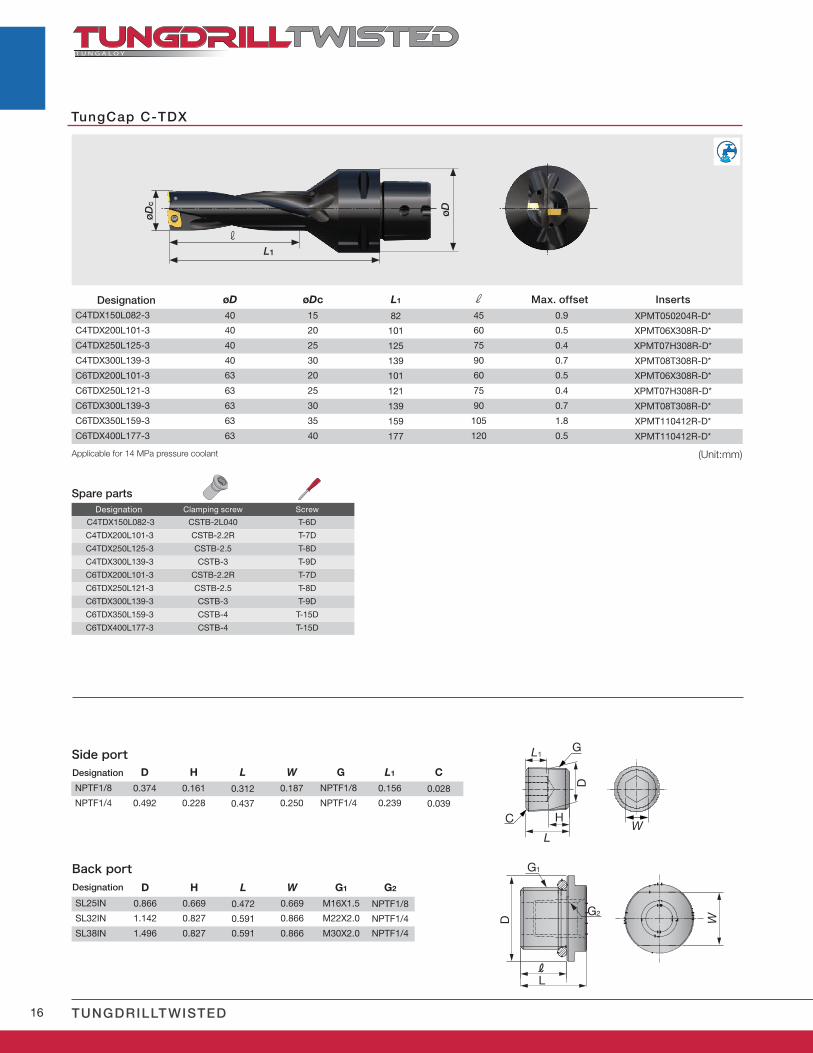
øD øDc L1 rC4TDX150L082-3 40 15 82 45 0.9 XPMT050204R-D*
C4TDX200L101-3 40 20 101 60 0.5 XPMT06X308R-D*
C4TDX250L125-3 40 25 125 75 0.4 XPMT07H308R-D*
C4TDX300L139-3 40 30 139 90 0.7 XPMT08T308R-D*
C6TDX200L101-3 63 20 101 60 0.5 XPMT06X308R-D*
C6TDX250L121-3 63 25 121 75 0.4 XPMT07H308R-D*
C6TDX300L139-3 63 30 139 90 0.7 XPMT08T308R-D*
C6TDX350L159-3 63 35 159 105 1.8 XPMT110412R-D*
C6TDX400L177-3 63 40 177 120 0.5 XPMT110412R-D*
TungCap C-TDX
C4TDX150L082-3 CSTB-2L040 T-6D
C4TDX200L101-3 CSTB-2.2R T-7D
C4TDX250L125-3 CSTB-2.5 T-8D
C4TDX300L139-3 CSTB-3 T-9D
C6TDX200L101-3 CSTB-2.2R T-7D
C6TDX250L121-3 CSTB-2.5 T-8D
C6TDX300L139-3 CSTB-3 T-9D
C6TDX350L159-3 CSTB-4 T-15D
C6TDX400L177-3 CSTB-4 T-15D
øD
L1
øD
c
r
D H L W G L1 CNPTF1/8 0.374 0.161 0.312 0.187 NPTF1/8 0.156 0.028
NPTF1/4 0.492 0.228 0.437 0.250 NPTF1/4 0.239 0.039
D H L W G1 G2
SL25IN 0.866 0.669 0.472 0.669 M16X1.5 NPTF1/8
SL32IN 1.142 0.827 0.591 0.866 M22X2.0 NPTF1/4
SL38IN 1.496 0.827 0.591 0.866 M30X2.0 NPTF1/4
L
H
D
L1
WC
G
R
D
G1
L
W
G2
Designation Max. offset Inserts
Spare partsClamping screw ScrewDesignation
Applicable for 14 MPa pressure coolant
Designation
Designation
Side port
(Unit:mm)
Back port
17w w w.t u n g a l oy a m e r i c a .c o m
A CC E L E R A T E D M A C H I N I N G
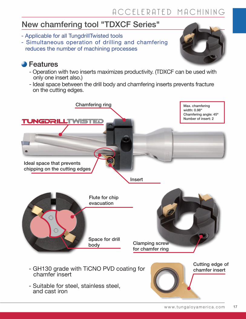
New chamfering tool "TDXCF Series"
- Operation with two inserts maximizes productivity. (TDXCF can be used with only one insert also.) - Ideal space between the drill body and chamfering inserts prevents fracture on the cutting edges.
- Applicable for all TungdrillTwisted tools- Simultaneous operation of drilling and chamfering
reduces the number of machining processes
Features
Clamping screw for chamfer ring
Flute for chipevacuation
Space for drill body
Insert
Ideal space that prevents chipping on the cutting edges
Chamfering ring Max. chamfering width: 0.98"Chamfering angle: 45ºNumber of insert: 2
- GH130 grade with TiCNO PVD coating for chamfer insert
Cutting edge of chamfer insert
- Suitable for steel, stainless steel, and cast iron
18 TUNGDRILLTWISTED
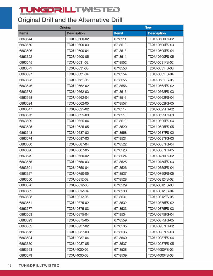
Original New
Item# Description Item# Description
6863544 TDXU-0500-02 6718511 TDXU-0500FS-02
6863570 TDXU-0500-03 6718512 TDXU-0500FS-03
6863596 TDXU-0500-04 6718513 TDXU-0500FS-04
6863622 TDXU-0500-05 6718514 TDXU-0500FS-05
6863545 TDXU-0531-02 6718552 TDXU-0531FS-02
6863571 TDXU-0531-03 6718553 TDXU-0531FS-03
6863597 TDXU-0531-04 6718554 TDXU-0531FS-04
6863623 TDXU-0531-05 6718555 TDXU-0531FS-05
6863546 TDXU-0562-02 6718556 TDXU-0562FS-02
6863572 TDXU-0562-03 6718515 TDXU-0562FS-03
6863598 TDXU-0562-04 6718516 TDXU-0562FS-04
6863624 TDXU-0562-05 6718557 TDXU-0562FS-05
6863547 TDXU-0625-02 6718517 TDXU-0625FS-02
6863573 TDXU-0625-03 6718518 TDXU-0625FS-03
6863599 TDXU-0625-04 6718519 TDXU-0625FS-04
6863625 TDXU-0625-05 6718520 TDXU-0625FS-05
6863548 TDXU-0687-02 6718558 TDXU-0687FS-02
6863574 TDXU-0687-03 6718521 TDXU-0687FS-03
6863600 TDXU-0687-04 6718522 TDXU-0687FS-04
6863626 TDXU-0687-05 6718523 TDXU-0687FS-05
6863549 TDXU-0750-02 6718524 TDXU-0750FS-02
6863575 TDXU-0750-03 6718525 TDXU-0750FS-03
6863601 TDXU-0750-04 6718526 TDXU-0750FS-04
6863627 TDXU-0750-05 6718527 TDXU-0750FS-05
6863550 TDXU-0812-02 6718528 TDXU-0812FS-02
6863576 TDXU-0812-03 6718529 TDXU-0812FS-03
6863602 TDXU-0812-04 6718530 TDXU-0812FS-04
6863628 TDXU-0812-05 6718531 TDXU-0812FS-05
6863551 TDXU-0875-02 6718532 TDXU-0875FS-02
6863577 TDXU-0875-03 6718533 TDXU-0875FS-03
6863603 TDXU-0875-04 6718534 TDXU-0875FS-04
6863629 TDXU-0875-05 6718559 TDXU-0875FS-05
6863552 TDXU-0937-02 6718535 TDXU-0937FS-02
6863578 TDXU-0937-03 6718536 TDXU-0937FS-03
6863604 TDXU-0937-04 6718560 TDXU-0937FS-04
6863630 TDXU-0937-05 6718537 TDXU-0937FS-05
6863553 TDXU-1000-02 6718538 TDXU-1000FS-02
6863579 TDXU-1000-03 6718539 TDXU-1000FS-03
Original Drill and the Alternative Drill
19w w w.t u n g a l oy a m e r i c a .c o m
A CC E L E R A T E D M A C H I N I N G
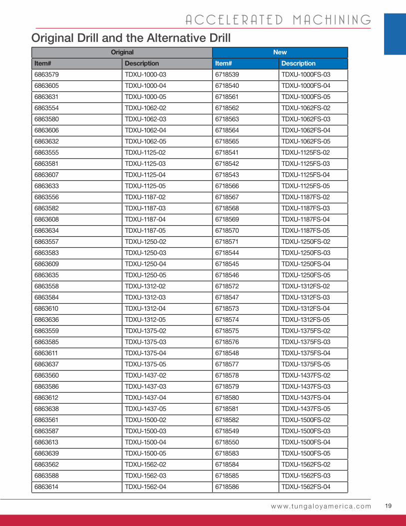
Original New
Item# Description Item# Description
6863579 TDXU-1000-03 6718539 TDXU-1000FS-03
6863605 TDXU-1000-04 6718540 TDXU-1000FS-04
6863631 TDXU-1000-05 6718561 TDXU-1000FS-05
6863554 TDXU-1062-02 6718562 TDXU-1062FS-02
6863580 TDXU-1062-03 6718563 TDXU-1062FS-03
6863606 TDXU-1062-04 6718564 TDXU-1062FS-04
6863632 TDXU-1062-05 6718565 TDXU-1062FS-05
6863555 TDXU-1125-02 6718541 TDXU-1125FS-02
6863581 TDXU-1125-03 6718542 TDXU-1125FS-03
6863607 TDXU-1125-04 6718543 TDXU-1125FS-04
6863633 TDXU-1125-05 6718566 TDXU-1125FS-05
6863556 TDXU-1187-02 6718567 TDXU-1187FS-02
6863582 TDXU-1187-03 6718568 TDXU-1187FS-03
6863608 TDXU-1187-04 6718569 TDXU-1187FS-04
6863634 TDXU-1187-05 6718570 TDXU-1187FS-05
6863557 TDXU-1250-02 6718571 TDXU-1250FS-02
6863583 TDXU-1250-03 6718544 TDXU-1250FS-03
6863609 TDXU-1250-04 6718545 TDXU-1250FS-04
6863635 TDXU-1250-05 6718546 TDXU-1250FS-05
6863558 TDXU-1312-02 6718572 TDXU-1312FS-02
6863584 TDXU-1312-03 6718547 TDXU-1312FS-03
6863610 TDXU-1312-04 6718573 TDXU-1312FS-04
6863636 TDXU-1312-05 6718574 TDXU-1312FS-05
6863559 TDXU-1375-02 6718575 TDXU-1375FS-02
6863585 TDXU-1375-03 6718576 TDXU-1375FS-03
6863611 TDXU-1375-04 6718548 TDXU-1375FS-04
6863637 TDXU-1375-05 6718577 TDXU-1375FS-05
6863560 TDXU-1437-02 6718578 TDXU-1437FS-02
6863586 TDXU-1437-03 6718579 TDXU-1437FS-03
6863612 TDXU-1437-04 6718580 TDXU-1437FS-04
6863638 TDXU-1437-05 6718581 TDXU-1437FS-05
6863561 TDXU-1500-02 6718582 TDXU-1500FS-02
6863587 TDXU-1500-03 6718549 TDXU-1500FS-03
6863613 TDXU-1500-04 6718550 TDXU-1500FS-04
6863639 TDXU-1500-05 6718583 TDXU-1500FS-05
6863562 TDXU-1562-02 6718584 TDXU-1562FS-02
6863588 TDXU-1562-03 6718585 TDXU-1562FS-03
6863614 TDXU-1562-04 6718586 TDXU-1562FS-04
Original Drill and the Alternative Drill
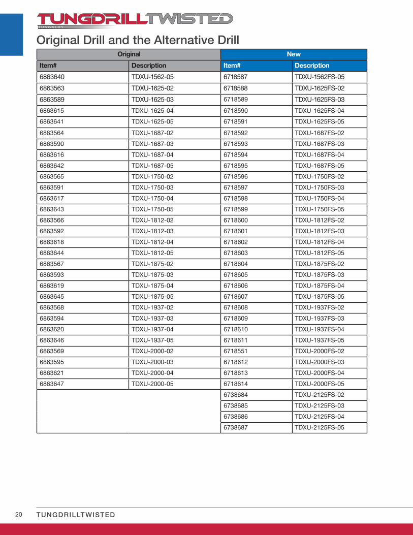
20 TUNGDRILLTWISTED
Original New
Item# Description Item# Description
6863640 TDXU-1562-05 6718587 TDXU-1562FS-05
6863563 TDXU-1625-02 6718588 TDXU-1625FS-02
6863589 TDXU-1625-03 6718589 TDXU-1625FS-03
6863615 TDXU-1625-04 6718590 TDXU-1625FS-04
6863641 TDXU-1625-05 6718591 TDXU-1625FS-05
6863564 TDXU-1687-02 6718592 TDXU-1687FS-02
6863590 TDXU-1687-03 6718593 TDXU-1687FS-03
6863616 TDXU-1687-04 6718594 TDXU-1687FS-04
6863642 TDXU-1687-05 6718595 TDXU-1687FS-05
6863565 TDXU-1750-02 6718596 TDXU-1750FS-02
6863591 TDXU-1750-03 6718597 TDXU-1750FS-03
6863617 TDXU-1750-04 6718598 TDXU-1750FS-04
6863643 TDXU-1750-05 6718599 TDXU-1750FS-05
6863566 TDXU-1812-02 6718600 TDXU-1812FS-02
6863592 TDXU-1812-03 6718601 TDXU-1812FS-03
6863618 TDXU-1812-04 6718602 TDXU-1812FS-04
6863644 TDXU-1812-05 6718603 TDXU-1812FS-05
6863567 TDXU-1875-02 6718604 TDXU-1875FS-02
6863593 TDXU-1875-03 6718605 TDXU-1875FS-03
6863619 TDXU-1875-04 6718606 TDXU-1875FS-04
6863645 TDXU-1875-05 6718607 TDXU-1875FS-05
6863568 TDXU-1937-02 6718608 TDXU-1937FS-02
6863594 TDXU-1937-03 6718609 TDXU-1937FS-03
6863620 TDXU-1937-04 6718610 TDXU-1937FS-04
6863646 TDXU-1937-05 6718611 TDXU-1937FS-05
6863569 TDXU-2000-02 6718551 TDXU-2000FS-02
6863595 TDXU-2000-03 6718612 TDXU-2000FS-03
6863621 TDXU-2000-04 6718613 TDXU-2000FS-04
6863647 TDXU-2000-05 6718614 TDXU-2000FS-05
6738684 TDXU-2125FS-02
6738685 TDXU-2125FS-03
6738686 TDXU-2125FS-04
6738687 TDXU-2125FS-05
Original Drill and the Alternative Drill
21
0.004 0.005
TD
XU
-081
2-03
(L/D
= 3
)
(N∙m) (N∙m)GH130TDXCF130L25 - TDXCF250L25
XHGX090700R-45A d CSPB-
4S T-15D 3.5CM6X16
P-57.0
TDXCF260L30 - TDXC-F540L30
CM8 x 20 8.0
TDXCF
OK
w w w.t u n g a l oy a m e r i c a .c o m
A CC E L E R A T E D M A C H I N I N G
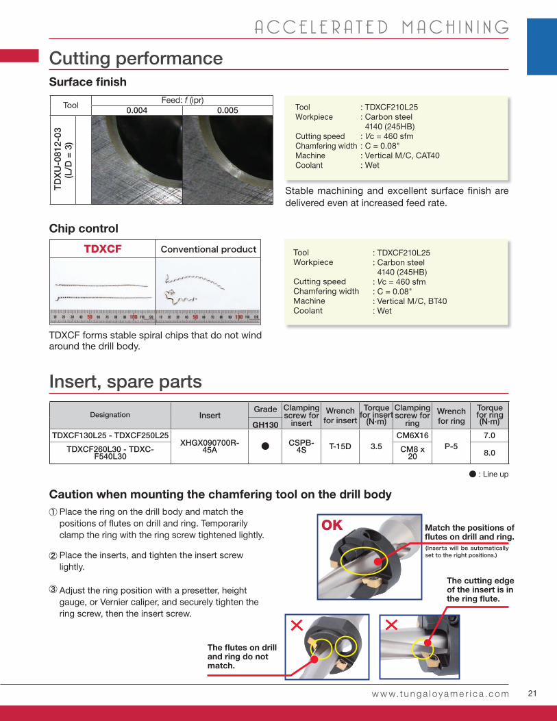
Cutting performance
Feed: f (ipr)Tool : TDXCF210L25
: Carbon steel 4140 (245HB): Vc = 460 sfm: C = 0.08": Vertical M/C, CAT40: Wet
Stable machining and excellent surface finish are delivered even at increased feed rate.
TDXCF forms stable spiral chips that do not wind around the drill body.
ToolWorkpiece
Cutting speed Chamfering widthMachine Coolant
Insert, spare parts
: TDXCF210L25: Carbon steel 4140 (245HB): Vc = 460 sfm: C = 0.08": Vertical M/C, BT40: Wet
ToolWorkpiece Cutting speedChamfering widthMachineCoolant
Conventional product
Designation Insert Grade Clamping
screw for insert
Torque for insert
Torque for ring
Clamping screw for
ring
Wrenchfor insert
Wrenchfor ring
● : Line up
Surface finish
Chip control
Caution when mounting the chamfering tool on the drill bodyPlace the ring on the drill body and match the positions of flutes on drill and ring. Temporarily clamp the ring with the ring screw tightened lightly.
Adjust the ring position with a presetter, height gauge, or Vernier caliper, and securely tighten the ring screw, then the insert screw.
Place the inserts, and tighten the insert screw lightly.
Match the positions of flutes on drill and ring.(Inserts will be automatically set to the right positions.)
The cutting edge of the insert is in the ring flute.
The flutes on drill and ring do not match.
22 TUNGDRILLTWISTED
L
øDc2
øDc øDs2
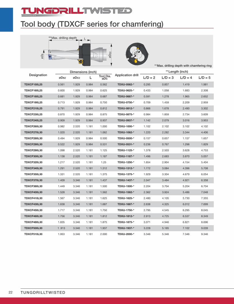
øDs2 øDc2 L øDc L/D = 2 L/D = 3 L/D = 4 L/D = 5
TDXCF150L25 0.561 1.929 0.984 0.562 TDXU-0562-* 0.295 0.857 1.419 1.981
TDXCF160L25 0.600 1.929 0.984 0.625 TDXU-0625-* 0.433 1.058 1.683 2.308
TDXCF180L25 0.681 1.929 0.984 0.687 TDXU-0687-* 0.591 1.278 1.965 2.652
TDXCF190L25 0.713 1.929 0.984 0.750 TDXU-0750-* 0.709 1.459 2.209 2.959
TDXCF210L25 0.791 1.929 0.984 0.812 TDXU-0812-* 0.866 1.678 2.490 3.302
TDXCF230L25 0.870 1.929 0.984 0.875 TDXU-0875-* 0.984 1.859 2.734 3.609
TDXCF240L25 0.909 1.929 0.984 0.937 TDXU-0937-* 1.142 2.079 3.016 3.953
TDXCF260L30 0.982 2.520 1.181 1.000 TDXU-1000-* 1.102 2.102 3.102 4.102
TDXCF270L30 1.020 2.520 1.181 1.062 TDXU-1062-* 1.220 2.282 3.344 4.406
TDXCF280L30 0.494 1.929 0.984 0.500 TDXU-0500-* 0.157 0.657 1.157 1.657
TDXCF290L30 0.522 1.929 0.984 0.531 TDXU-0531-* 0.236 0.767 1.298 1.829
TDXCF290L30 1.098 2.520 1.181 1.125 TDXU-1125-* 1.378 2.503 3.628 4.753
TDXCF300L30 1.138 2.520 1.181 1.187 TDXU-1187-* 1.496 2.683 3.870 5.057
TDXCF320L30 1.217 2.520 1.181 1.25 TDXU-1250-* 1.654 2.904 4.154 5.404
TDXCF340L30 1.291 2.520 1.181 1.312 TDXU-1312-* 1.772 3.084 4.396 5.708
TDXCF350L30 1.331 2.520 1.181 1.375 TDXU-1375-* 1.929 3.304 4.679 6.054
TDXCF370L30 1.409 3.346 1.181 1.437 TDXU-1437-* 2.047 3.484 4.921 6.358
TDXCF380L30 1.449 3.346 1.181 1.500 TDXU-1500-* 2.204 3.704 5.204 6.704
TDXCF400L30 1.528 3.346 1.181 1.562 TDXU-1562-* 2.362 3.924 5.486 7.048
TDXCF410L30 1.567 3.346 1.181 1.625 TDXU-1625-* 2.480 4.105 5.730 7.355
TDXCF430L30 1.638 3.346 1.181 1.687 TDXU-1687-* 2.638 4.325 6.012 7.699
TDXCF450L30 1.717 3.346 1.181 1.750 TDXU-1750-* 2.795 4.545 6.295 8.045
TDXCF460L30 1.756 3.346 1.181 1.812 TDXU-1812-* 2.913 4.725 6.537 8.349
TDXCF480L30 1.835 3.346 1.181 1.875 TDXU-1875-* 3.071 4.946 6.821 8.696
TDXCF500L30 1 .913 3.346 1.181 1.937 TDXU-1937-* 3.228 5.165 7.102 9.039
TDXCF510L30 1.953 3.346 1.181 2.000 TDXU-2000-* 3.346 5.346 7.346 9.346
Tool body (TDXCF series for chamfering)
**Max. drilling depth
Designation Application drillTool Dia.
**Length (inch)Dimensions (inch)
**Max. drilling depth with chamfering ring
23
L
øD
L2
G
ød
J
S.s.
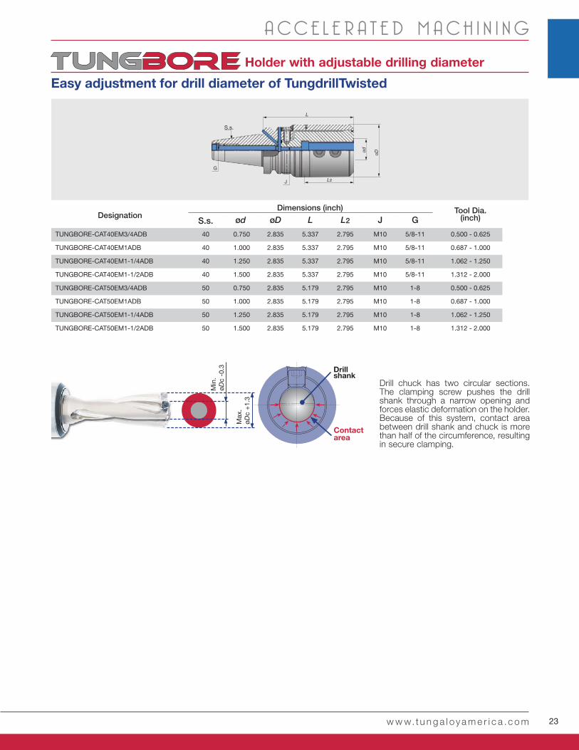
Drill chuck has two circular sections. The clamping screw pushes the drill shank through a narrow opening and forces elastic deformation on the holder. Because of this system, contact area between drill shank and chuck is more than half of the circumference, resulting in secure clamping.
Drillshank
Contact area
Holder with adjustable drilling diameter
Easy adjustment for drill diameter of TungdrillTwisted
Max
.øD
c +
1.3
Min
.øD
c -0
.3S.s. ød øD L L2 J G
TUNGBORE-CAT40EM3/4ADB 40 0.750 2.835 5.337 2.795 M10 5/8-11 0.500 - 0.625
TUNGBORE-CAT40EM1ADB 40 1.000 2.835 5.337 2.795 M10 5/8-11 0.687 - 1.000
TUNGBORE-CAT40EM1-1/4ADB 40 1.250 2.835 5.337 2.795 M10 5/8-11 1.062 - 1.250
TUNGBORE-CAT40EM1-1/2ADB 40 1.500 2.835 5.337 2.795 M10 5/8-11 1.312 - 2.000
TUNGBORE-CAT50EM3/4ADB 50 0.750 2.835 5.179 2.795 M10 1-8 0.500 - 0.625
TUNGBORE-CAT50EM1ADB 50 1.000 2.835 5.179 2.795 M10 1-8 0.687 - 1.000
TUNGBORE-CAT50EM1-1/4ADB 50 1.250 2.835 5.179 2.795 M10 1-8 1.062 - 1.250
TUNGBORE-CAT50EM1-1/2ADB 50 1.500 2.835 5.179 2.795 M10 1-8 1.312 - 2.000
Dimensions (inch)Designation
Tool Dia.(inch)
w w w.t u n g a l oy a m e r i c a .c o m
A CC E L E R A T E D M A C H I N I N G
24 TUNGDRILLTWISTED
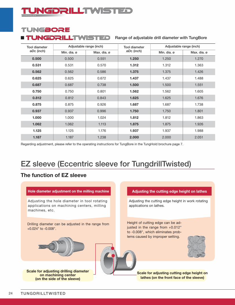
0.500 0.500 0.551 1.250 1.250 1.270
0.531 0.531 0.570 1.312 1.312 1.363
0.562 0.562 0.586 1.375 1.375 1.426
0.625 0.625 0.672 1.437 1.437 1.488
0.687 0.687 0.738 1.500 1.500 1.551
0.750 0.750 0.801 1.562 1.562 1.605
0.812 0.812 0.843 1.625 1.625 1.676
0.875 0.875 0.926 1.687 1.687 1.738
0.937 0.937 0.996 1.750 1.750 1.801
1.000 1.000 1.024 1.812 1.812 1.863
1.062 1.062 1.113 1.875 1.875 1.926
1.125 1.125 1.176 1.937 1.937 1.988
1.187 1.187 1.238 2.000 2.000 2.051
EZ sleeve (Eccentric sleeve for TungdrillTwisted)The function of EZ sleeve
Hole diameter adjustment on the milling machine
Adjusting the hole diameter in tool rotating applications on machining centers, mill ing machines, etc.
Drilling diameter can be adjusted in the range from +0.024" to -0.008".
Adjusting the cutting edge height on lathes
Adjusting the cutting edge height in work rotating applications on lathes.
Height of cutting edge can be ad-justed in the range from +0.012" to -0.008", which eliminates prob-lems caused by improper setting.
Scale for adjusting drilling diameter on machining center
(on the side of the sleeve)
Scale for adjusting cutting edge height on lathes (on the front face of the sleeve)
Range of adjustable drill diameter with TungBore
Regarding adjustment, please refer to the operating instructions for TungBore in the TungHold brochure page 7.
Tool diameter øDc (inch)
Adjustable range (inch)
Min. dia. ø Max. dia. ø
Tool diameterøDc (inch)
Adjustable range (inch)
Min. dia. ø Max. dia. ø
25
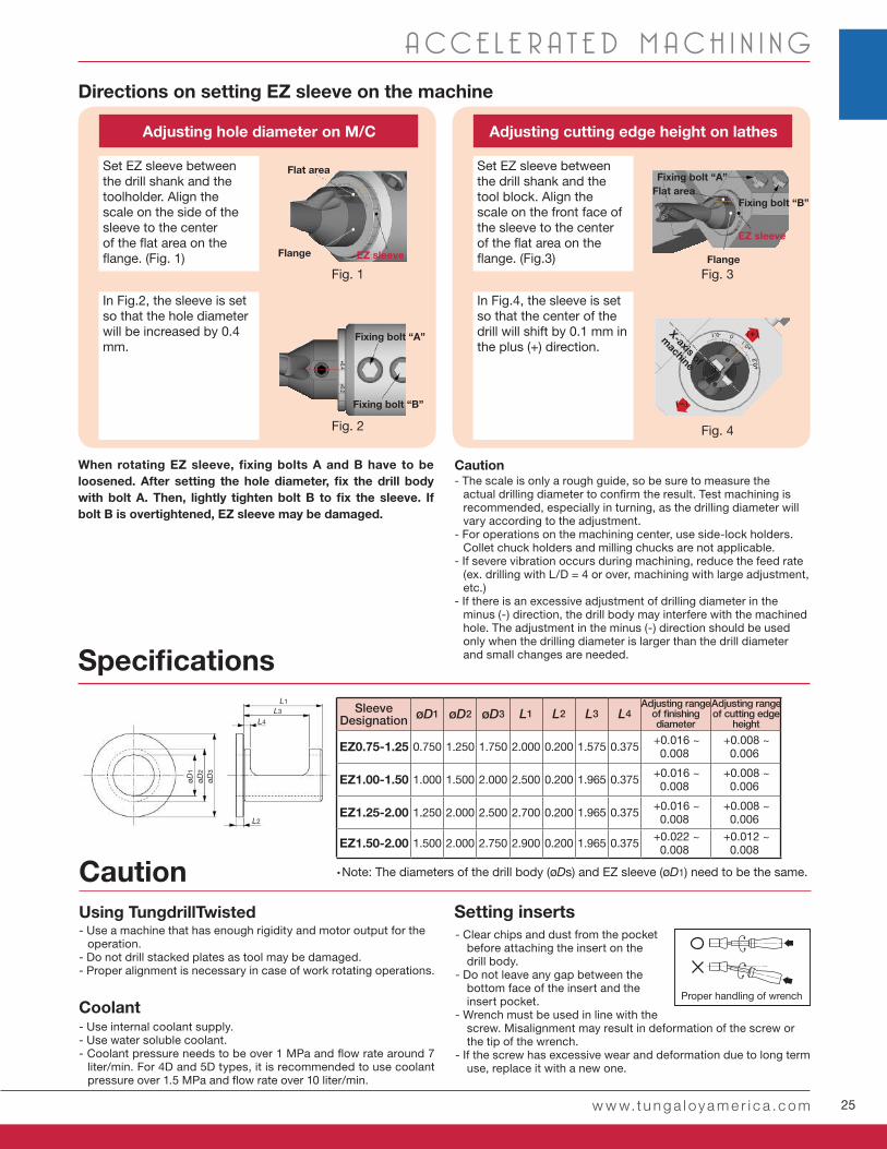
øD1 øD2 øD3 L1 L2 L3 L4
EZ0.75-1.25 0.750 1.250 1.750 2.000 0.200 1.575 0.375 +0.016 ~ 0.008
+0.008 ~ 0.006
EZ1.00-1.50 1.000 1.500 2.000 2.500 0.200 1.965 0.375 +0.016 ~ 0.008
+0.008 ~ 0.006
EZ1.25-2.00 1.250 2.000 2.500 2.700 0.200 1.965 0.375 +0.016 ~ 0.008
+0.008 ~ 0.006
EZ1.50-2.00 1.500 2.000 2.750 2.900 0.200 1.965 0.375 +0.022 ~ 0.008
+0.012 ~ 0.008
øD1
øD2
øD3
L1
L2
L3
L4
+0.4+0.2
(+)
(-)
w w w.t u n g a l oy a m e r i c a .c o m
A CC E L E R A T E D M A C H I N I N G
- Use a machine that has enough rigidity and motor output for the operation.
- Do not drill stacked plates as tool may be damaged. - Proper alignment is necessary in case of work rotating operations.
- Clear chips and dust from the pocket before attaching the insert on the drill body.
- Do not leave any gap between the bottom face of the insert and the insert pocket.
- Wrench must be used in line with the screw. Misalignment may result in deformation of the screw or the tip of the wrench.
- If the screw has excessive wear and deformation due to long term use, replace it with a new one.
- Use internal coolant supply. - Use water soluble coolant. - Coolant pressure needs to be over 1 MPa and flow rate around 7
liter/min. For 4D and 5D types, it is recommended to use coolant pressure over 1.5 MPa and flow rate over 10 liter/min.
Using TungdrillTwisted
Coolant
Setting inserts
Specifications
•Note: The diameters of the drill body (øDs) and EZ sleeve (øD1) need to be the same. Caution
Proper handling of wrench
Adjusting range of finishing diameter
Adjusting range of cutting edge
height
Directions on setting EZ sleeve on the machine
Caution- The scale is only a rough guide, so be sure to measure the
actual drilling diameter to confirm the result. Test machining is recommended, especially in turning, as the drilling diameter will vary according to the adjustment.
- For operations on the machining center, use side-lock holders. Collet chuck holders and milling chucks are not applicable.
- If severe vibration occurs during machining, reduce the feed rate (ex. drilling with L/D = 4 or over, machining with large adjustment, etc.)
- If there is an excessive adjustment of drilling diameter in the minus (-) direction, the drill body may interfere with the machined hole. The adjustment in the minus (-) direction should be used only when the drilling diameter is larger than the drill diameter and small changes are needed.
When rotating EZ sleeve, fixing bolts A and B have to be loosened. After setting the hole diameter, fix the drill body with bolt A. Then, lightly tighten bolt B to fix the sleeve. If bolt B is overtightened, EZ sleeve may be damaged.
Adjusting hole diameter on M/C Adjusting cutting edge height on lathes
In Fig.2, the sleeve is set so that the hole diameter will be increased by 0.4 mm.
Fixing bolt “A”
Flange
EZ sleeve
Fixing bolt “B”
Set EZ sleeve between the drill shank and the toolholder. Align the scale on the side of the sleeve to the center of the flat area on the flange. (Fig. 1)
Set EZ sleeve between the drill shank and the tool block. Align the scale on the front face of the sleeve to the center of the flat area on the flange. (Fig.3)
In Fig.4, the sleeve is set so that the center of the drill will shift by 0.1 mm in the plus (+) direction.
Fixing bolt “A”
Fixing bolt “B”
EZ sleeve
X-axis of
machine
Flat area
Flat area
Flange
SleeveDesignation
Fig. 1 Fig. 3
Fig. 2 Fig. 4
26 TUNGDRILLTWISTED
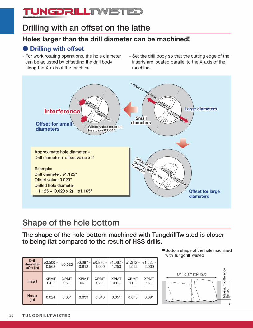
ø0.500 - 0.562 ø0.625 ø0.687 -
0.812ø0.875 -
1.000ø1.062 -
1.250ø1.312 -
1.562ø1.625 -
2.000
XPMT04...
XPMT05...
XPMT06...
XPMT07...
XPMT08...
XPMT11...
XPMT15...
0.024 0.031 0.039 0.043 0.051 0.075 0.091
Holes larger than the drill diameter can be machined!
- For work rotating operations, the hole diameter can be adjusted by offsetting the drill body along the X-axis of the machine.
Offset for small diameters
Offset for large diameters
Approximate hole diameter = Drill diameter + offset value x 2
Example: Drill diameter: ø1.125"Offset value: 0.020"Drilled hole diameter = 1.125 + (0.020 x 2) = ø1.165"
● Drilling with offset
Interference
Offset value must be less than 0.004".
Large diameters
Small diameters
Drilling with an offset on the lathe
X-axis of machine
Offset value (+)
depends on the drill
diameter.
Central insert
Central insertPeripheral insert
Peripheral insert
Central insertPeripheral insert
- Set the drill body so that the cutting edge of the inserts are located parallel to the X-axis of the machine.
The shape of the hole bottom machined with TungdrillTwisted is closer to being flat compared to the result of HSS drills.
DrilldiameterøDc (in)
Shape of the hole bottom
Hmax (in)
Insert
Bottom shape of the hole machined with TungdrillTwisted
Drill diameter øDc
Max
imum
diff
eren
ce
Hm
ax
27
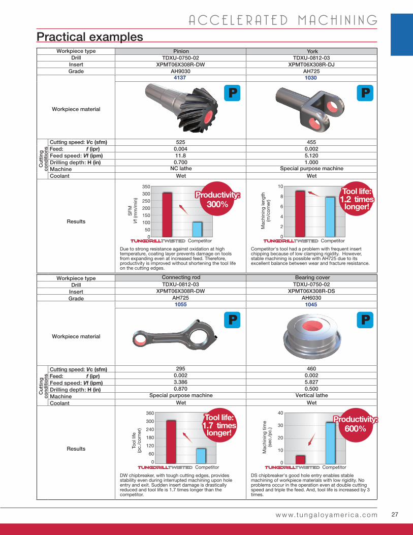
TDXU-0750-02 TDXU-0812-03XPMT06X308R-DW XPMT06X308R-DJ
AH9030 AH725
525 4550.004 0.00211.8 5.1200.700 1.000
TDXU-0812-03 TDXU-0750-02XPMT06X308R-DW XPMT06X308R-DS
AH725 AH6030
295 4600.002 0.0023.386 5.8270.870 0.500
350
300
250
200
150
100
50
0
360
300
240
180
120
60
0
10
8
6
4
2
0
40
30
20
10
0
w w w.t u n g a l oy a m e r i c a .c o m
A CC E L E R A T E D M A C H I N I N GPractical examples
Pinion
Connecting rod
4137
1055
Workpiece typeDrill
InsertGrade
Workpiece material
Cutting speed: Vc (sfm) Feed: f (ipr) Feed speed: Vf (ipm) Drilling depth: H (in) Machine Coolant
Results
Cut
ting
cond
itio
ns
NC latheWet
Special purpose machineWet
Special purpose machineWet
Vertical latheWet
Due to strong resistance against oxidation at high temperature, coating layer prevents damage on tools from expanding even at increased feed. Therefore, productivity is improved without shortening the tool life on the cutting edges.
DW chipbreaker, with tough cutting edges, provides stability even during interrupted machining upon hole entry and exit. Sudden insert damage is drastically reduced and tool life is 1.7 times longer than the competitor.
Competitor's tool had a problem with frequent insert chipping because of low clamping rigidity. However, stable machining is possible with AH725 due to its excellent balance between wear and fracture resistance.
DS chipbreaker's good hole entry enables stable machining of workpiece materials with low rigidity. No problems occur in the operation even at double cutting speed and triple the feed. And, tool life is increased by 3 times.
Productivity:300%
Tool life: 1.2 times
longer!
Tool life: 1.7 times
longer!
Competitor
Competitor
Competitor
Competitor
SFM
Vf (
mm
/min
)To
ol li
fe(p
c./c
orne
r)
Mac
hini
ng le
ngth
(m/c
orne
r)M
achi
ning
tim
e(s
ec./
pc.
)
1030
1045
York
Bearing cover
Productivity:600%
Workpiece typeDrill
InsertGrade
Workpiece material
Cutting speed: Vc (sfm) Feed: f (ipr) Feed speed: Vf (ipm) Drilling depth: H (in) Machine Coolant
Results
Cut
ting
cond
itio
ns
28 TUNGDRILLTWISTED
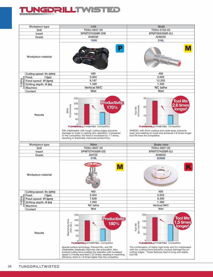
TDXU-0937-03 TDXU-0750-03XPMT07H308R-DW XPMT06X308R-DJ
AH6030 AH6030
490 4900.004 0.0058.187 12.2051.348 1.300
TDXU-0937-02 TDXU-0937-02XPMT07H308R-DS XPMT07H308R-DJ
AH725 AH9030
460 4900.004 0.0037.638 6.3001.000 1.380
250
200
150
100
50
0
250
200
150
100
50
0
30
20
10
0
200
150
100
50
0
Link
Valve
1045
316L
Vertical M/CWet
NC latheWet
NC latheWet
Vertical M/CWet
DW chipbreaker with tough cutting edges prevents damage on tools in casting skin operation. Compared to the competitor, the feed is increased by 1.7 times, resulting in drastically improved productivity.
Special surface technology, PremiumTec, and DS chipbreaker drastically improves chip evacuation. Also, lowered cutting force enables the operation with increased speed (1.4 times) and feed (1.25 times), resulting in machining efficiency which is 1.8 times higher than the competitor.
AH6030, with thick coating and oxide layer, prevents wear and welding on tools and achieves 2.6 times longer tool life than the competitor.
The combination of highly rigid body and DJ chipbreaker with low cutting force prevents unusual damage the on cutting edges. These features lead to long and stable tool life.
Tool life: 2.6 times longer!
Tool life: 1.5 times longer!
Competitor
Competitor
Competitor
Competitor
SFM
Vf (
mm
/min
)M
achi
ning
tim
e(m
in./
pc.
)
Tool
life
(m/c
orne
r)To
ol li
fe(p
c./c
orne
r)
316L
G3500
Shaft
Brake rotor
Productivity:170%
Productivity:180%
Workpiece typeDrill
InsertGrade
Workpiece material
Cutting speed: Vc (sfm) Feed: f (ipr) Feed speed: Vf (ipm) Drilling depth: H (in) Machine Coolant
Results
Cut
ting
cond
itio
ns
Workpiece typeDrill
InsertGrade
Workpiece material
Cutting speed: Vc (sfm) Feed: f (ipr) Feed speed: Vf (ipm) Drilling depth: H (in) Machine Coolant
Results
Cut
ting
cond
itio
ns

29w w w.t u n g a l oy a m e r i c a .c o m
Check our site and our App to get more info!

www.tungaloyamer ica .com
f a c e b o o k . c o m / t u n g a l o y a m e r i c at w i t t e r . c o m / t u n g a l o y
follow us at:
www.youtube.com/tungaloycorporation
Tungaloy Canada432 Elgin St. Unit 3, Brantford, Ontario N3S 7P7, CanadaPhone: +1-519-758-5779 Fax: +1-519-758-5791www.tungaloy.com/ca
Tungaloy de Mexico S.A.C Los Arellano 113, Parque Industrial Siglo XXIAguascalientes, AGS, Mexico 20290Phone:+52-449-929-5410 Fax:+52-449-929-5411www.tungaloy.com/mx
Tungaloy America, Inc.3726 N Ventura Drive, Arlington Heights, IL 60004, U.S.A.Inside Sales: +1-888-554-8394Technical Support: +1-888-554-8391 Fax: +1-888-554-8392www.tungaloyamerica.com
T U N G A LOY
MillLine
The most effective tooling solution with the option of hundreds of tools! Tool changeover times can be measurably reduced!
Please check out our other
products from MillLine!
Distributed by:
Feb. 2017 (TA)
To see this product in action visit:
Scan for instant web access
D O W N L O A DDr. Carbide App