Embed Size (px)
Citation preview

www.tungaloyamerica.com
User ´s Guide
Tungaloy G001
G002
G029
G084
USER´S GUIDE
Par ts for Tools
Technica l Reference
Alphanumer ic Index
Use
r´s G
uide
www.tungaloyamerica.comG002
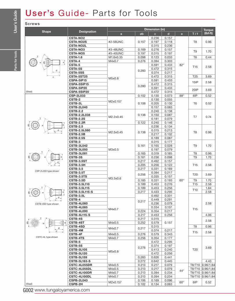
a øb c d e T / fCSTA-NO2
#2-56UNC 0.157
0.236 0.157
82°
T8 0.96CSTA-NO2S 0.197 0.118
CSTA-NO2L 0.315 0.236
CSTA-NO3 #3-48UNC 0.169 0.276 0.157T9 1.70
CSTA-NO5 #5-40UNC 0.197 0.315 0.197
CSTA-1.6 M1.6x0.35 0.098 0.123 0.033 T6 0.44
CSTA-4 M4x0.7 0.276 0.394 0.303
T15 2.58CSTA-5
M5x0.8
0.283
0.591 0.433
CSTA-5S 0.472 0.315
CSTA-5SS 0.374 0.217
CSTA-5ST25 0.472 0.315 T25 3.69
CSPA-5IP15
0.280
0.591 0.43315IP 2.58
CSPA-5SIP15 0.472 0.315
CSPA-5IP20 0.591 0.43320IP 3.69
CSPA-5SIP20 0.472 0.315
CSP-2L033
M2x0.157
0.102 0.130 0.073 88° 6IP 0.52
CSTB-20.106
0.130 0.055
60°
T6 0.52CSTB-2L 0.205 0.130
CSTB-2L040 0.157 0.083
CSTB-2.2
M2.2x0.450.138
0.240 0.138
T7 0.74CSTB-2.2L038 0.150 0.087
CSTB-2.2S 0.181 0.079
CSTB-2.2R 0.122 0.240 0.146
CSTB-2.5
M2.5x0.45 0.138
0.236 0.134
T8 0.96CSTB-2.5L080 0.315 0.213
CSTB-2.5B 0.217 0.102
CSTB-2.5S 0.189 0.087
CSTB-3
M3x0.5
0.161
0.315 0.177
T9 1.70CSTB-3L042 0.165 0.028
CSTB-3L050 0.197 0.079
CSTB-3L081 0.165 0.319 0.185 T8 0.96
CSTB-3S 0.161 0.236 0.098 T9 1.70
CSTB-3.5ST
M3.5x0.6
0.217 0.492 0.157
T15 2.58CSTB-3.5H 0.205 0.256 0.122
CSTB-3.5 0.217 0.331 0.169
CSTB-3.5T0.256
0.394 0.217T20 3.69
CSTB-3.5TS 0.335 0.157
CSTB-3.5D 0.185 0.331 0.193 T9 1.70
CSTB-3.5L110 0.189 0.453 0.276 T15 2.58
CSTB-3.5L115 0.189 0.453 0.256T10
1.84
CSTB-3.5L115-S 0.217 0.433 0.295 2.58
CSTB-3.5L
0.217
0.492 0.331
T15
2.58
CSTB-4
M4x0.7
0.449 0.291
CSTB-4L060 0.236 0.079
CSTB-4L085 0.334 0.137
CSTB-4L090 0.224 0.354 0.217
CSTB-4L115-S 0.217 0.453 0.256 4.06
CSTB-4S 0.217 0.315
0.1572.58
CSTB-4ST M4x0.5 0.252 0.579
CSTB-4SDM4x0.7 0.217
0.315 T8 0.96
CSTB-4M 0.374 0.217T15 2.58
CSTB-4F M4x0.5 0.276 0.579 0.343
CSTB-4TS M4x0.7 0.256 0.354 0.177
T203.69
CSTB-5
M5x0.8
0.276
0.472 0.295
CSTB-5S 0.374 0.197
CSTB-5L105 0.413 0.240
CSTB-5L120 0.472 0.256
CSTB-5L159 0.283 0.626 0.441
CSTB-5L163-S 0.272 0.642 0.445 4.43
CSTC-4L055DR M4x0.5 0.213 0.217 0.079
44°
T8/T10 0.96/1.84
CSTC-4L055DL M4x0.5 0.213 0.217 0.079 T8/T10 0.96/1.84
CSTC-4L100DR M4x0.7 0.213 0.394 0.234 T8/T10 0.96/1.84
CSTC-4L100DL M4x0.7 0.213 0.394 0.234 T8/T10 0.96/1.84
CSPB-2L043M2x0.157
0.106 0.169 0.09660° 6IP 0.52
CSPB-2H 0.102 0.134 0.063
a
c
d
øbe
T
a
d
c
eøb
T
a
d
c
eøb
T
d
c
eøb
T
aa
dc
eøb
T
Part
s fo
r too
ls
CSTB-4SD type shown
CSP-2L033 type shown
Screws
Shape DesignationDimension (in) Torque
(lbf.ft)
CSTC-4L type shown
User’s Guide- Parts for Tools
(Steel)
(Steel)
Use
r´s G
uide
Tungaloy G003
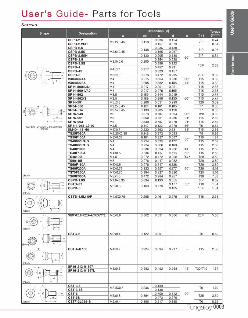
a øb c d e T / fCSPB-2.2
M2.2x0.45 0.1180.236 0.154
60°
7IP0.74
CSPB-2.2SH 0.157 0.079 0.81
CSPB-2.5M2.5x0.45
0.1380.236 0.138
8IP 0.96CSPB-2.5S 0.165 0.067
CSPB-2.5SH 0.130 0.205 0.130 7IP 0.81
CSPB-3.5M3.5x0.6 0.205
0.354 0.220
15IP 2.58CSPB-3.5S 0.256 0.122
CSPB-4M4x0.7 0.217
0.457 0.291
CSPB-4S 0.323 0.157
CSPB-5 M5x0.8 0.276 0.472 0.295 20IP 3.69
VX040024A M4 0.215 0.354 0.236 60° T15 3.32
VX040028A M4 0.205 0.382 0.185 44° T15 3.32
SR14-500/L5.1 M4 0.217 0.201 0.091
60°
T15 2.58
SR14-500-L7.0 M4 0.217 0.276 0.165 T15 2.58
SR14-562 M3.5 0.189 0.344 0.219 T10
SR14-562/S M3.5 0.189 0.256 0.130 T10
SR14-591 M5x0.8 0.260 0.531 0.299 T20 3.69
SR34-508 M2.2x0.45 0.124 0.181 0.105 T7 0.66
SR34-514 M2.5x0.45 0.130 0.205 0.126 T7 0.66
SR76-943 M6 0.378 0.787 0.394 90° T20 3.69
SR76-961 M5 0.260 0.531 0.286 61° T15 2.58
SR76-963 M5 0.339 0.787 0.378 91° T15 2.58
SR114-018-L3.40 M2.5 0.142 0.132 0.079 56° T6 0.52
SM40-143-H0 M4X0.7 0.220 0.563 0.331 61° T15 2.58
TS25F080A M2.25X0.35 0.146 0.272 0.083
60°
T8 0.96
TS30F100A M3X0.35 0.181 0.327 0.087 T10 1.84
TS40085I/HG M4 0.224 0.335 0.177 T15 2.58
TS40093I/HG M4 0.224 0.366 0.169 T15 2.58
TS40B100I M4 0.236 0.394 0.236 R3.0 T15 2.58
TS40F120A M4X0.5 0.236 0.417 0.118 60° T15 2.58
TS45120I M4.5 0.272 0.472 0.295 R3.5 T20 3.69
TS50115I M5 0.276 0.447 0.252
60°
T20 3.69
TS50F160A M5X0.5 0.276 0.547 0.138 T20 3.69
TS60F200A M6X0.75 0.323 0.657 0.177 T20 5.16
TS70F250A M7X0.75 0.394 0.827 0.220 T25 5.16
TS80F300A M8X1.0 0.472 0.984 0.287 T30 7.38
CSPD-1.8S M1.8x0.35 0.094 0.130 0.055
55°
6IP 0.52
CSTD-3TM3x0.5 0.169 0.276
0.177 T10 1.84
CSPD-3 0.165 10IP 1.84
CSTB-4.5L110P M4.5X0.75 0.206 0.461 0.276 56° T15 2.58
SRM5X0.8IP20X+ACROLYTE M5X0.8 0.362 0.591 0.386 70° 20IP 5.53
CSTC-2 M2x0.4 0.122 0.201 - - T6 0.52
CSTR-4L100 M4x0.7 0.224 0.394 0.217 - T15 2.58
SR16-212-01397M5x0.8 0.252 0.492 0.268 43° T20/T10 1.84
SR16-212-01397L
CST-3.5M3.5X0.6 0.236
0.189 -
90°
T9 1.70CST-3.5S 0.138 -
CST-5M5x0.8 0.394
0.709 0.512T25 3.69
CST-5S 0.472 0.276
CSTF-2L055-S M2x0.4 0.106 0.217 0.150 T6 0.52
a
dc
eøb
T
c
aøb
T
ee a
dc
T
øb
a
d
c
eøb
T
c
aøb
T
e
c
a
d
øb
TT
øbe
dc
a
T
d
c
eøb
T
a
Part
s fo
r too
ls
Screws
Shape DesignationDimension (in) Torque
(lbf.ft)
SCREW TORX M4 L=9.5MM type shown
User’s Guide- Parts for Tools
(Steel)
(Steel)
(Steel)
(Steel)
(Steel)
(Steel)
(Steel)
(Steel)
2.58
2.58
Use
r´s G
uide
www.tungaloyamerica.comG004
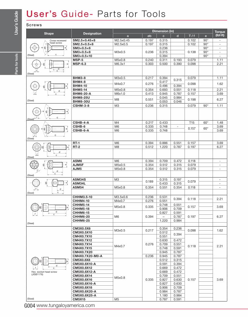
a øb c d T / f eSM2.5×0.45×8 M2.5x0.45 0.197 0.315 0.102 90° -
SM2.5×0.5×8 M2.5x0.5 0.197 0.315 0.102 90° -
SM3×0.5×6M3x0.5 0.236
0.236
0.138
90° -
SM3×0.5×8 0.315 90° -
SM3×0.5×10 0.394 90° -
MSP-5 M5x0.8 0.240 0.311 0.193 0.079 1.11
MSP-6.3 M6.3x1 0.303 0.500 0.390 0.098 2.21
BHM3-8 M3x0.5 0.217 0.3940.315
0.079 1.11
BHM4-8M4x0.7 0.276
0.4170.098 1.62
BHM4-10 0.496 0.394
BHM5-14 M5x0.8 0.354 0.693 0.551 0.118 2.21
BHM6-20-A M6x1.0 0.413 0.945 0.787 0.157 3.69
BHM8-25UM8 0.551
0.045 0.9840.198 6.27
BHM8-30U 0.053 0.046
CSHM-3-8 M3 0.236 0.315 0.079 90° 1.11
CSHB-4-A M4 0.217 0.433 T15 60° 1.48
CSHB-6 M6 0.335 0.748 -0.157 60°
3.69
CSHB-6-A M6 0.335 0.748 3.69
RT-1 M6 0.394 0.886 0.551 0.157 3.69
RT-2 M8 0.512 1.220 0.787 0.197 6.27
ASM6 M6 0.394 0.709 0.472 0.118 -
AJM5F M5x0.5 0.354 0.512 0.315 0.079 -
AJM5 M5x0.8 0.354 0.512 0.315 0.079 -
ASM34S M30.189
0.315 0.1970.079
-
ASM34L 0.433 0.315 -
ASM54 M5x0.8 0.354 0.551 0.354 0.118 -
CHHM3.5-10 M3.5x0.6 0.236 0.5310.394 0.118 2.21
CHHM4-10 M4x0.7 0.276 0.551
CHHM5-14M5x0.8 0.335
0.748 0.5510.157 3.69
CHHM5-18 0.906 0.709
CHHM6-15M6 0.394
0.827 0.591
0.197 6.27CHHM6-20 - 0.787
CHHM6-25 1.220 0.984
CM3X0.5X6M3x0.5 0.217
0.354 0.2360.098 1.62
CM3X0.5X10 0.5120.394
CM4X0.7X10
M4x0.70.276
0.551
0.118 2.21
CM4X0.7X12 0.630 0.472
CM4X0.7X14 0.709 0.551
CM4X0.7X15 0.748 0.591
CM4X0.7X20 0.945 0.787
CM4X0.7X20-M0-A 0.236 0.945 0.787
CM5X0.8X8
M5x0.80.335
0.512 0.315
0.157 3.69
CM5X0.8X10-A 0.591 0.394
CM5X0.8X12 0.669 0.472
CM5X0.8X12-A 0.669 0.472
CM5X0.8X14 0.709 0.551
CM5X0.8X16 0.827 0.630
CM5X0.8X16-A 0.827 0.630
CM5X0.8X18 0.906 0.709
CM5X0.8X20-A 0.984 0.787
CM5X0.8X25-A 1.180 0.984
CM5X15 M5 0.787 0.591
øb
c
aeø
b
cd
f
a
øb
c
d
a
f
f
a
c
øbe
f
a
c
øbe
f
øb
c
d
a
øb a
cdf
øb a
c
f d
øb
cfd
a
øb
cfd
a
Part
s fo
r too
ls
Cross recessed head screw
Screws
Shape DesignationDimension (in) Torque
(lbf.ft)
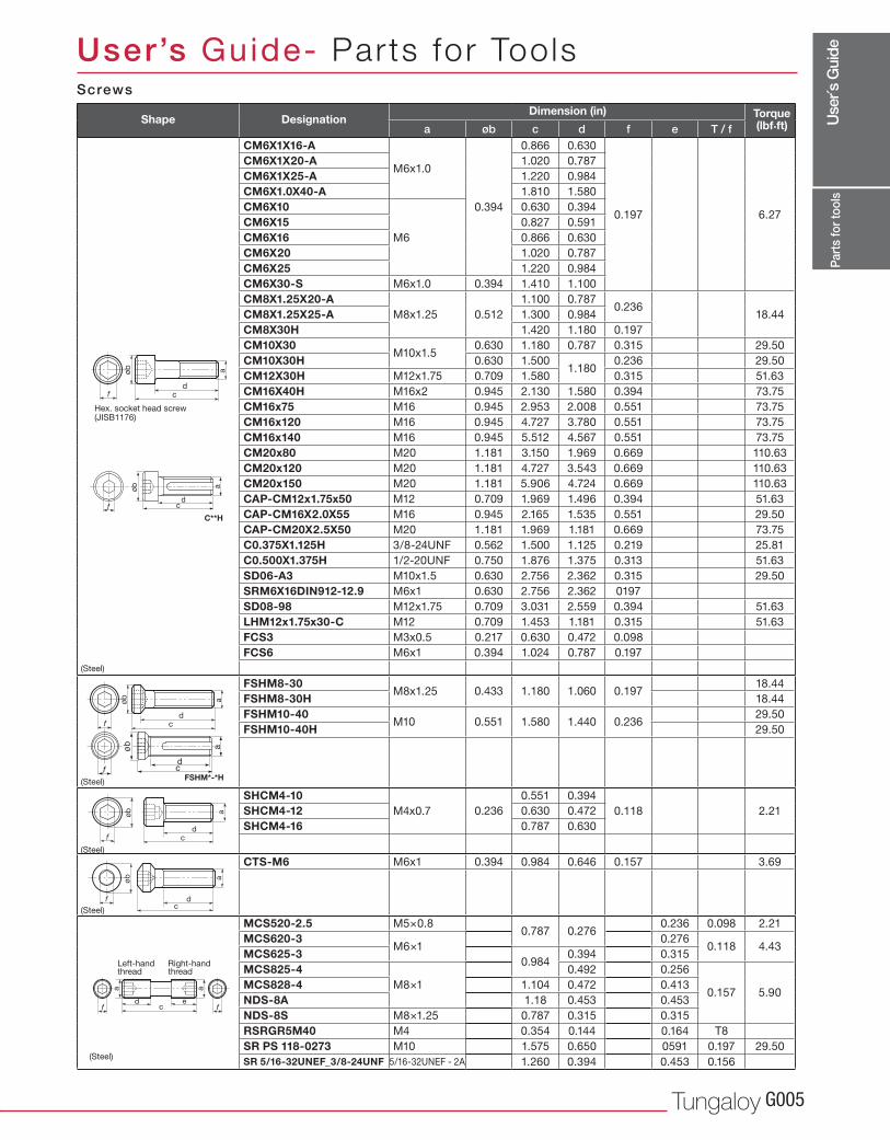
Hex. socket head screw (JISB1176)
User’s Guide- Parts for Tools
(Steel)
(Steel)
(Steel)
(Steel)
(Steel)
(Steel)
(Steel)
(Steel)
(Steel)
(Steel)
Use
r´s G
uide
Tungaloy G005
a øb c d f e T / fCM6X1X16-A
M6x1.0
0.394
0.866 0.630
0.197 6.27
CM6X1X20-A 1.020 0.787
CM6X1X25-A 1.220 0.984
CM6X1.0X40-A 1.810 1.580
CM6X10
M6
0.630 0.394
CM6X15 0.827 0.591
CM6X16 0.866 0.630
CM6X20 1.020 0.787
CM6X25 1.220 0.984
CM6X30-S M6x1.0 0.394 1.410 1.100
CM8X1.25X20-AM8x1.25 0.512
1.100 0.7870.236
18.44CM8X1.25X25-A 1.300 0.984
CM8X30H 1.420 1.180 0.197
CM10X30M10x1.5
0.630 1.180 0.787 0.315 29.50
CM10X30H 0.630 1.5001.180
0.236 29.50
CM12X30H M12x1.75 0.709 1.580 0.315 51.63
CM16X40H M16x2 0.945 2.130 1.580 0.394 73.75
CM16x75 M16 0.945 2.953 2.008 0.551 73.75
CM16x120 M16 0.945 4.727 3.780 0.551 73.75
CM16x140 M16 0.945 5.512 4.567 0.551 73.75
CM20x80 M20 1.181 3.150 1.969 0.669 110.63
CM20x120 M20 1.181 4.727 3.543 0.669 110.63
CM20x150 M20 1.181 5.906 4.724 0.669 110.63
CAP-CM12x1.75x50 M12 0.709 1.969 1.496 0.394 51.63
CAP-CM16X2.0X55 M16 0.945 2.165 1.535 0.551 29.50
CAP-CM20X2.5X50 M20 1.181 1.969 1.181 0.669 73.75
C0.375X1.125H 3/8-24UNF 0.562 1.500 1.125 0.219 25.81
C0.500X1.375H 1/2-20UNF 0.750 1.876 1.375 0.313 51.63
SD06-A3 M10x1.5 0.630 2.756 2.362 0.315 29.50
SRM6X16DIN912-12.9 M6x1 0.630 2.756 2.362 0197
SD08-98 M12x1.75 0.709 3.031 2.559 0.394 51.63
LHM12x1.75x30-C M12 0.709 1.453 1.181 0.315 51.63
FCS3 M3x0.5 0.217 0.630 0.472 0.098
FCS6 M6x1 0.394 1.024 0.787 0.197
FSHM8-30M8x1.25 0.433 1.180 1.060 0.197
18.44
FSHM8-30H 18.44
FSHM10-40M10 0.551 1.580 1.440 0.236
29.50
FSHM10-40H 29.50
SHCM4-10M4x0.7 0.236
0.551 0.394
0.118 2.21SHCM4-12 0.630 0.472
SHCM4-16 0.787 0.630
CTS-M6 M6x1 0.394 0.984 0.646 0.157 3.69
MCS520-2.5 M5×0.80.787 0.276
0.236 0.098 2.21
MCS620-3M6×1
0.2760.118 4.43
MCS625-30.984
0.394 0.315
MCS825-4M8×1
0.492 0.256
0.157 5.90MCS828-4 1.104 0.472 0.413
NDS-8A 1.18 0.453 0.453
NDS-8S M8×1.25 0.787 0.315 0.315
RSRGR5M40 M4 0.354 0.144 0.164 T8
SR PS 118-0273 M10 1.575 0.650 0591 0.197 29.50
SR 5/16-32UNEF_3/8-24UNF 5/16-32UNEF - 2A 1.260 0.394 0.453 0.156
øb
cfd
a
C**H
cfd
aøb
cf d
aøb
øb
cfd
a
FSHM*-*H
f fcd e
aa
Part
s fo
r too
ls
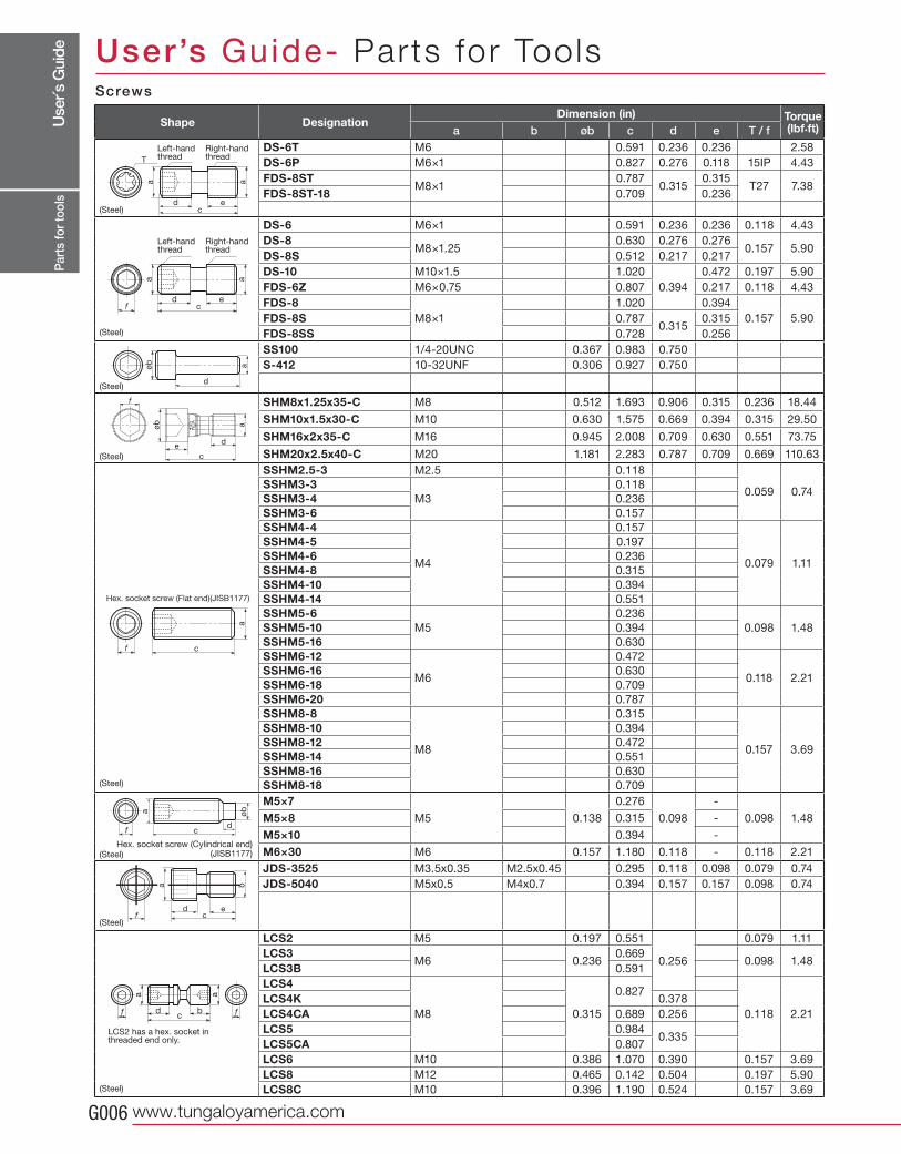
Hex. socket head screw (JISB1176)
Screws
Shape DesignationDimension (in) Torque
(lbf.ft)
User’s Guide- Parts for Tools
(Steel)
(Steel)
(Steel)
(Steel)
Left-hand thread
Right-hand thread
(Steel)
Use
r´s G
uide
www.tungaloyamerica.comG006
a b øb c d e T / fDS-6T M6 0.591 0.236 0.236 2.58
DS-6P M6×1 0.827 0.276 0.118 15IP 4.43
FDS-8STM8×1
0.7870.315
0.315T27 7.38
FDS-8ST-18 0.709 0.236
DS-6 M6×1 0.591 0.236 0.236 0.118 4.43
DS-8M8×1.25
0.630 0.276 0.2760.157 5.90
DS-8S 0.512 0.217 0.217
DS-10 M10×1.5 1.020
0.394
0.472 0.197 5.90
FDS-6Z M6×0.75 0.807 0.217 0.118 4.43
FDS-8M8×1
1.020 0.394
0.157 5.90FDS-8S 0.7870.315
0.315
FDS-8SS 0.728 0.256
SS100 1/4-20UNC 0.367 0.983 0.750
S-412 10-32UNF 0.306 0.927 0.750
SHM8x1.25x35-C M8 0.512 1.693 0.906 0.315 0.236 18.44
SHM10x1.5x30-C M10 0.630 1.575 0.669 0.394 0.315 29.50
SHM16x2x35-C M16 0.945 2.008 0.709 0.630 0.551 73.75
SHM20x2.5x40-C M20 1.181 2.283 0.787 0.709 0.669 110.63
SSHM2.5-3 M2.5 0.118
0.059 0.74SSHM3-3
M3
0.118
SSHM3-4 0.236
SSHM3-6 0.157
SSHM4-4
M4
0.157
0.079 1.11
SSHM4-5 0.197
SSHM4-6 0.236
SSHM4-8 0.315
SSHM4-10 0.394
SSHM4-14 0.551
SSHM5-6M5
0.236
0.098 1.48SSHM5-10 0.394
SSHM5-16 0.630
SSHM6-12
M6
0.472
0.118 2.21SSHM6-16 0.630
SSHM6-18 0.709
SSHM6-20 0.787
SSHM8-8
M8
0.315
0.157 3.69
SSHM8-10 0.394
SSHM8-12 0.472
SSHM8-14 0.551
SSHM8-16 0.630
SSHM8-18 0.709
M5×7M5 0.138
0.276
0.098
-
0.098 1.48M5×8 0.315 -
M5×10 0.394 -
M6×30 M6 0.157 1.180 0.118 - 0.118 2.21
JDS-3525 M3.5x0.35 M2.5x0.45 0.295 0.118 0.098 0.079 0.74
JDS-5040 M5x0.5 M4x0.7 0.394 0.157 0.157 0.098 0.74
M5x0.5 "M4
LCS2 M5 0.197 0.551
0.256
0.079 1.11
LCS3M6 0.236
0.6690.098 1.48
LCS3B 0.591
LCS4
M8 0.315
0.827
0.118 2.21
LCS4K 0.378
LCS4CA 0.689 0.256
LCS5 0.9840.335
LCS5CA 0.807
LCS6 M10 0.386 1.070 0.390 0.157 3.69
LCS8 M12 0.465 0.142 0.504 0.197 5.90
LCS8C M10 0.396 1.190 0.524 0.157 3.69
cd e
aa
T
f cd e
aa
f c
a
f cd
øba
cd e
ba
f
d
aøb
c
f
d
aøb
e
f fcd b
aa
Part
s fo
r too
ls
Hex. socket screw (Flat end)(JISB1177)
Left-hand thread
Left-hand thread
Right-hand thread
Right-hand thread
Hex. socket screw (Cylindrical end)(JISB1177)
Screws
Shape DesignationDimension (in) Torque
(lbf.ft)
User’s Guide- Parts for Tools
(Steel)
(Steel)
(Steel)
(Steel)
(Steel)
(Steel)
(Steel)
LCS2 has a hex. socket in threaded end only.
(Steel)
Use
r´s G
uide
Tungaloy G007
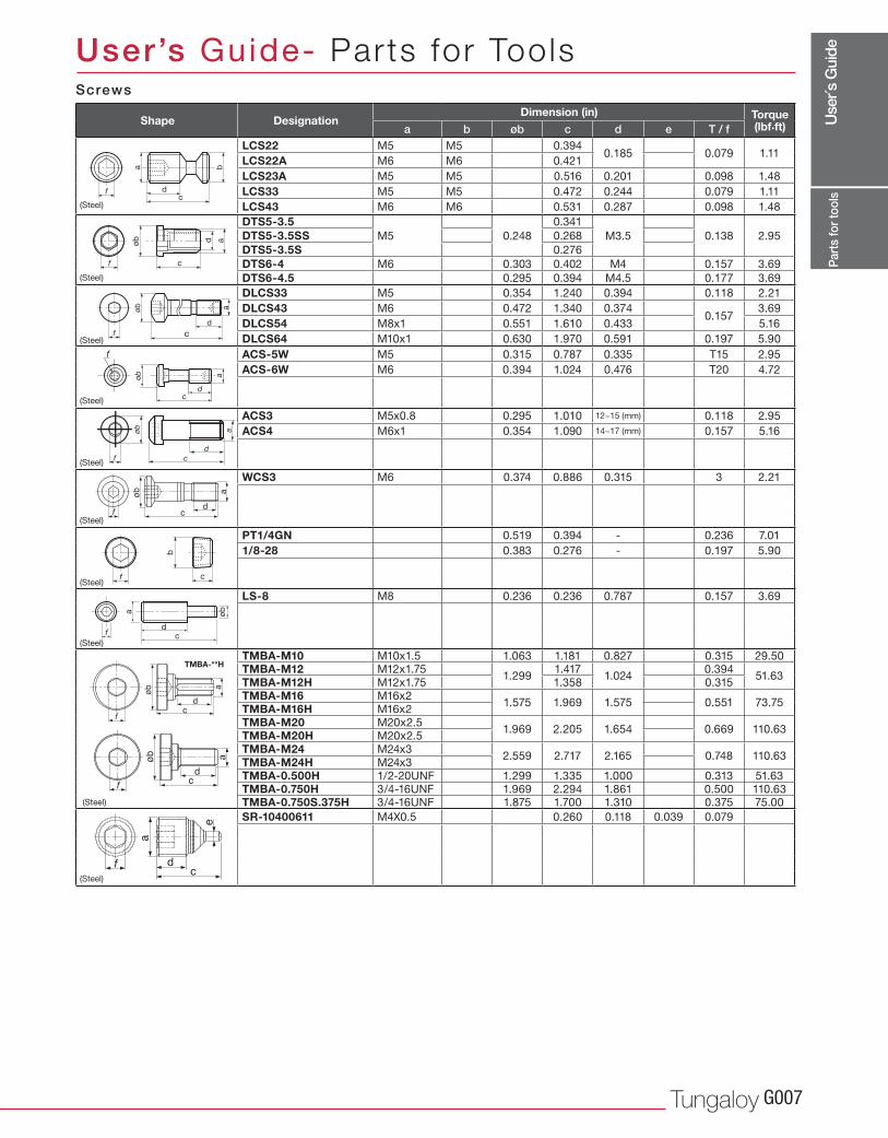
a b øb c d e T / fLCS22 M5 M5 0.394
0.185 0.079 1.11LCS22A M6 M6 0.421
LCS23A M5 M5 0.516 0.201 0.098 1.48
LCS33 M5 M5 0.472 0.244 0.079 1.11
LCS43 M6 M6 0.531 0.287 0.098 1.48
DTS5-3.5M5 0.248
0.341
M3.5 0.138 2.95DTS5-3.5SS 0.268
DTS5-3.5S 0.276
DTS6-4 M6 0.303 0.402 M4 0.157 3.69
DTS6-4.5 0.295 0.394 M4.5 0.177 3.69
DLCS33 M5 0.354 1.240 0.394 0.118 2.21
DLCS43 M6 0.472 1.340 0.3740.157
3.69
DLCS54 M8x1 0.551 1.610 0.433 5.16
DLCS64 M10x1 0.630 1.970 0.591 0.197 5.90
ACS-5W M5 0.315 0.787 0.335 T15 2.95
ACS-6W M6 0.394 1.024 0.476 T20 4.72
ACS3 M5x0.8 0.295 1.010 12~15 (mm) 0.118 2.95
ACS4 M6x1 0.354 1.090 14~17 (mm) 0.157 5.16
WCS3 M6 0.374 0.886 0.315 3 2.21
PT1/4GN 0.519 0.394 - 0.236 7.01
1/8-28 0.383 0.276 - 0.197 5.90
LS-8 M8 0.236 0.236 0.787 0.157 3.69
TMBA-M10 M10x1.5 1.063 1.181 0.827 0.315 29.50TMBA-M12 M12x1.75
1.2991.417
1.0240.394
51.63TMBA-M12H M12x1.75 1.358 0.315
TMBA-M16 M16x21.575 1.969 1.575 0.551 73.75TMBA-M16H M16x2
TMBA-M20 M20x2.51.969 2.205 1.654 0.669 110.63TMBA-M20H M20x2.5
TMBA-M24 M24x32.559 2.717 2.165 0.748 110.63TMBA-M24H M24x3
TMBA-0.500H 1/2-20UNF 1.299 1.335 1.000 0.313 51.63
TMBA-0.750H 3/4-16UNF 1.969 2.294 1.861 0.500 110.63TMBA-0.750S.375H 3/4-16UNF 1.875 1.700 1.310 0.375 75.00
SR-10400611 M4X0.5 0.260 0.118 0.039 0.079
fc
d
ba
f c
adøb
f c
d
aøb
cd
aøb
f
f c
b
øba
cd
f
a
dc
f
øb
TMBA-**H
dcf
a
e
Part
s fo
r too
ls
Screws
Shape DesignationDimension (in) Torque
(lbf.ft)
User’s Guide- Parts for Tools
(Steel)
(Steel)
(Steel)
(Steel)
(Steel)
(Steel)
(Steel)
(Steel)
(Steel)
(Steel)
Use
r´s G
uide
www.tungaloyamerica.comG008
a b c ød
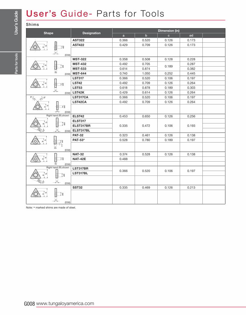
(D30)
AST322 0.366 0.520 0.126 0.173
AST422 0.429 0.709 0.126 0.173
(D30)
MST-322 0.358 0.508 0.128 0.228
MST-432 0.492 0.7050.189
0.287
MST-533 0.614 0.874 0.382
MST-644 0.740 1.050 0.252 0.445
(D30)
LST317 0.366 0.520 0.106 0.197
LST42 0.492 0.709 0.126 0.264
LST53 0.618 0.878 0.189 0.303
LST42K 0.429 0.614 0.126 0.264
(D30)
LST317CA 0.366 0.520 0.106 0.197
LST42CA 0.492 0.709 0.126 0.264
(D30)
ELST42 0.453 0.650 0.126 0.256
ELST317
0.335 0.472 0.106 0.193ELST317BR
ELST317BL
(D30)
PAT-32 0.323 0.461 0.126 0.138
PAT-53* 0.528 0.780 0.189 0.197
(D30)
NAT-32 0.374 0.528 0.126 0.138
NAT-42E 0.488
(D30)
LST317BR0.366 0.520 0.106 0.197
LST317BL
(D30)
SST32 0.335 0.469 0.126 0.213
b
a ød
c
b
ød
c
a
b
ød
c
a
b
ød
c
a
8° 8°
b
a ød
c
10°25°
b
ød
c
a
11
°
b
a ød
c
b
a ød
c
10°29°
b
a ød
c
Part
s fo
r too
ls
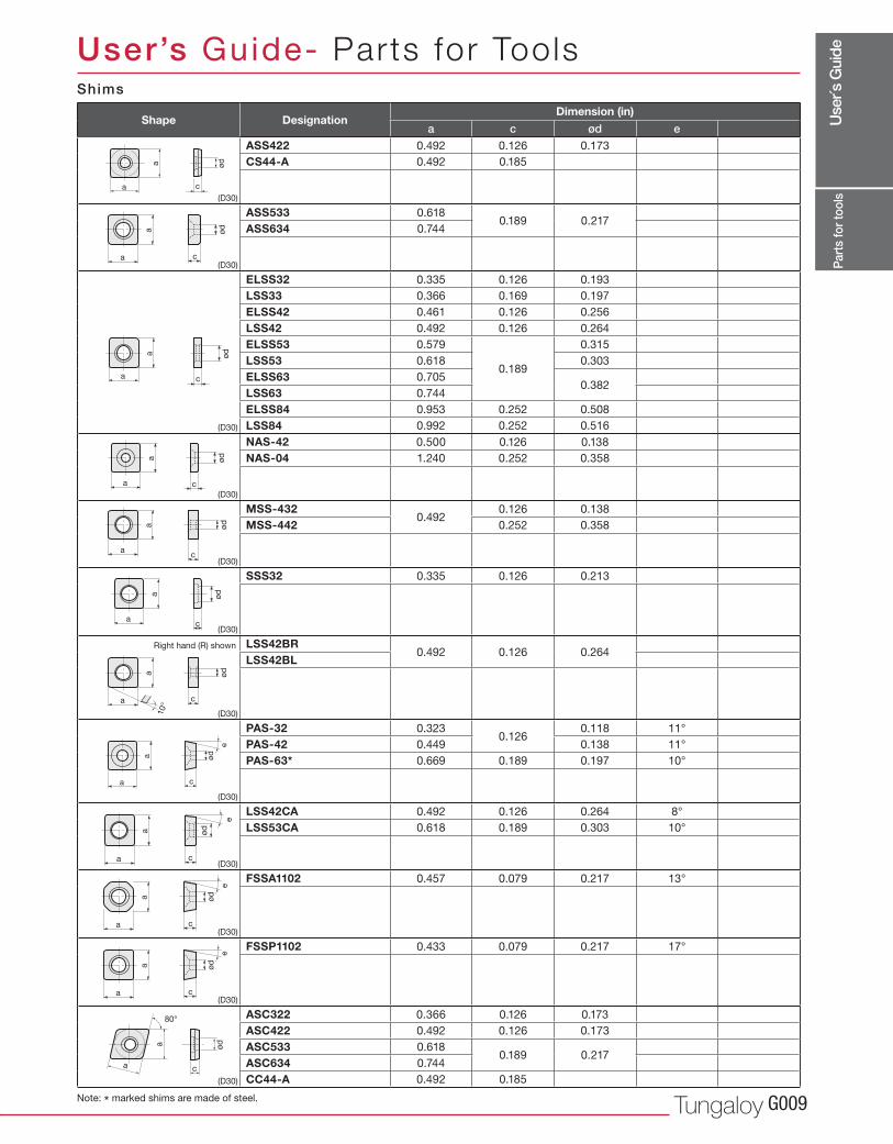
Note: * marked shims are made of steel.
Right hand (R) shown
Right hand (R) shown
Shims
Shape DesignationDimension (in)
User’s Guide- Parts for Tools
Use
r´s G
uide
Tungaloy G009
a c ød e
(D30)
ASS422 0.492 0.126 0.173
CS44-A 0.492 0.185
(D30)
ASS533 0.6180.189 0.217
ASS634 0.744
(D30)
ELSS32 0.335 0.126 0.193
LSS33 0.366 0.169 0.197
ELSS42 0.461 0.126 0.256
LSS42 0.492 0.126 0.264
ELSS53 0.579
0.189
0.315
LSS53 0.618 0.303
ELSS63 0.7050.382
LSS63 0.744
ELSS84 0.953 0.252 0.508
LSS84 0.992 0.252 0.516
(D30)
NAS-42 0.500 0.126 0.138
NAS-04 1.240 0.252 0.358
(D30)
MSS-4320.492
0.126 0.138
MSS-442 0.252 0.358
(D30)
SSS32 0.335 0.126 0.213
(D30)
LSS42BR0.492 0.126 0.264
LSS42BL
(D30)
PAS-32 0.3230.126
0.118 11°
PAS-42 0.449 0.138 11°
PAS-63* 0.669 0.189 0.197 10°
(D30)
LSS42CA 0.492 0.126 0.264 8°
LSS53CA 0.618 0.189 0.303 10°
(D30)
FSSA1102 0.457 0.079 0.217 13°
(D30)
FSSP1102 0.433 0.079 0.217 17°
(D30)
ASC322 0.366 0.126 0.173
ASC422 0.492 0.126 0.173
ASC533 0.6180.189 0.217
ASC634 0.744
CC44-A 0.492 0.185
a
a
ød
c
a
a
ød
c
a
a
ød
c
a
a
ød
c
a
a
ød
c
10°
a
a
ød
c
e
a
a
ød
c
e
a
a
ød
c
e
a
ød
c
e
a
a
a
ød
c
ød
c
80°
a
a
a
a
ød
c
Part
s fo
r too
ls
Note: * marked shims are made of steel.
Right hand (R) shown
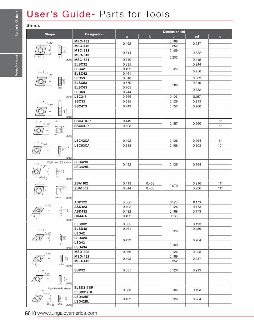
Shims
Shape DesignationDimension (in)
User’s Guide- Parts for Tools
Use
r´s G
uide
www.tungaloyamerica.comG010
a b c ød e
(D30)
MSC-4320.492
0.1890.287
MSC-442 0.252
MSC-5330.614
0.1890.382
MSC-5430.252
MSC-634 0.740 0.445
(D30)
ELSC32 0.335
0.126
0.244
LSC42 0.4920.256
ELSC42 0.461
LSC53 0.618
0.189
0.303
ELSC53 0.579 0.319
ELSC63 0.7050.382
LSC63 0.744
LSC317 0.366 0.106 0.197
(D30)
SSC32 0.335 0.126 0.213
SSC4T3 0.449 0.157 0.260
(D30)
SSC4T3-P 0.4490.157 0.260
5°
SSC54-P 0.528 5°
(D30)
LSC42CA 0.492 0.126 0.264 8°
LSC53CA 0.618 0.189 0.303 10°
(D30)
LSC42BR0.492 0.126 0.264
LSC42BL
(D30)
ZSA1102 0.413 0.4330.079
0.216 11°
ZSA1502 0.614 0.488 0.236 11°
(D30)
ASD322 0.366 0.126 0.173
ASD423 0.492 0.126 0.173
ASD432 0.492 0.189 0.173
CD44-A 0.492 0.185
(D30)
ELSD32 0.335
0.126
0.193
ELSD42 0.461 0.256
LSD42
0.492 0.264LSD42ALSD43
0.189LSD43A
(D30)
MSD-322 0.366 0.126 0.228
MSD-4320.492
0.1890.287
MSD-442 0.252
(D30)
SSD32 0.335 0.126 0.213
(D30)
ELSD317BR0.335 0.106 0.193
ELSD317BLLSD42BR
0.492 0.126 0.264LSD42BL
ød
c
80°
a
a
c
a
a
ød
80°
c
a
a
ød
80°
c
a
a
ød
80°
e
c
a
a
ød
80°
e
c
a
a
ød
80°
10°
c
a ød
b
e
c
øda
55°
a
c
øda
a
55°
a
a
55°
c
ød
a
55°
10° c
ød
a
c
øda
a
55°
Part
s fo
r too
ls
Right hand (R) shown
Right hand (R) shown
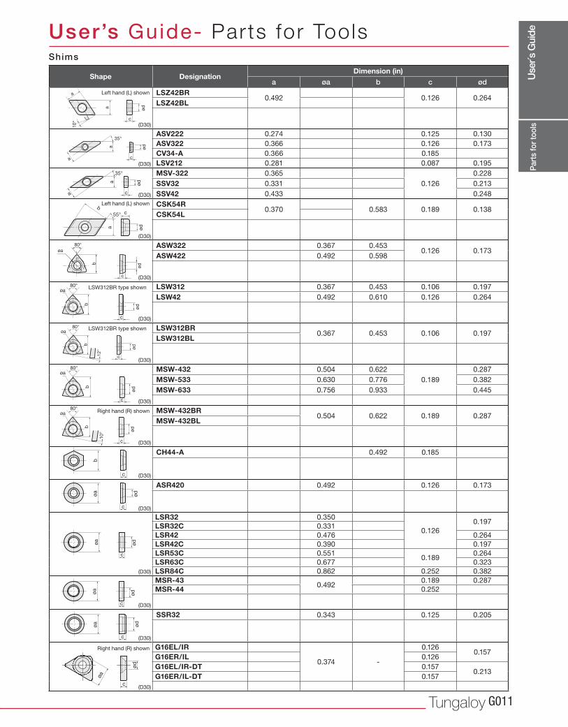
Shims
Shape DesignationDimension (in)
User’s Guide- Parts for Tools
Use
r´s G
uide
Tungaloy G011
a øa b c ød
(D30)
LSZ42BR0.492 0.126 0.264
LSZ42BL
(D30)
ASV222 0.274 0.125 0.130
ASV322 0.366 0.126 0.173
CV34-A 0.366 0.185
LSV212 0.281 0.087 0.195
(D30)
MSV-322 0.365
0.126
0.228
SSV32 0.331 0.213
SSV42 0.433 0.248
(D30)
CSK54R0.370 0.583 0.189 0.138
CSK54L
(D30)
ASW322 0.367 0.4530.126 0.173
ASW422 0.492 0.598
(D30)
LSW312 0.367 0.453 0.106 0.197
LSW42 0.492 0.610 0.126 0.264
(D30)
LSW312BR0.367 0.453 0.106 0.197
LSW312BL
(D30)
MSW-432 0.504 0.622
0.189
0.287
MSW-533 0.630 0.776 0.382
MSW-633 0.756 0.933 0.445
(D30)
MSW-432BR0.504 0.622 0.189 0.287
MSW-432BL
(D30)
CH44-A 0.492 0.185
(D30)
ASR420 0.492 0.126 0.173
(D30)
LSR32 0.350
0.126
0.197LSR32C 0.331
LSR42 0.476 0.264
LSR42C 0.390 0.197
LSR53C 0.5510.189
0.264
LSR63C 0.677 0.323
LSR84C 0.862 0.252 0.382
(D30)
MSR-430.492
0.189 0.287
MSR-44 0.252
(D30)
SSR32 0.343 0.125 0.205
(D30)
G16EL/IR
0.374 -
0.1260.157
G16ER/IL 0.126
G16EL/IR-DT 0.1570.213
G16ER/IL-DT 0.157
80°
øa
b
c
ød
c
ødb
øa80°
10°
c
a
55°
ød
b
80°
c
ødb
øa
80°
c
ødb
øa
12
°
c
øa
ød
80°
c
ødb
øa
c
øa
ød
c
øa
ød
c
øa
ød
ød
c
a
a
35°
ød
c
a
a
35°
10
°
a
c
ød
aøa
ød
c
c
b
Part
s fo
r too
ls
Left hand (L) shown
Left hand (L) shown
Right hand (R) shown
LSW312BR type shown
LSW312BR type shown
Right hand (R) shown
Shims
Shape DesignationDimension (in)
User’s Guide- Parts for Tools
Use
r´s G
uide
www.tungaloyamerica.comG012
øa R
(D30)
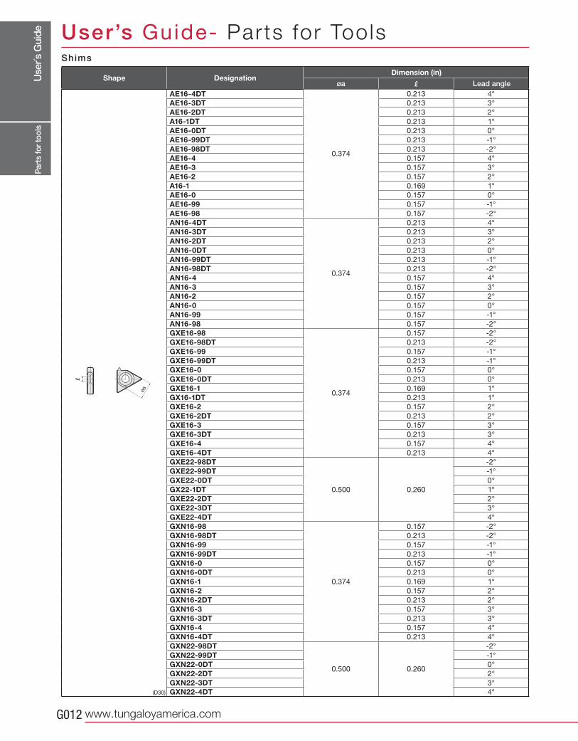
AE16-4DT
0.374
0.213 4°
AE16-3DT 0.213 3°
AE16-2DT 0.213 2°
A16-1DT 0.213 1°
AE16-0DT 0.213 0°
AE16-99DT 0.213 -1°
AE16-98DT 0.213 -2°
AE16-4 0.157 4°
AE16-3 0.157 3°
AE16-2 0.157 2°
A16-1 0.169 1°
AE16-0 0.157 0°
AE16-99 0.157 -1°
AE16-98 0.157 -2°
AN16-4DT
0.374
0.213 4°
AN16-3DT 0.213 3°
AN16-2DT 0.213 2°
AN16-0DT 0.213 0°
AN16-99DT 0.213 -1°
AN16-98DT 0.213 -2°
AN16-4 0.157 4°
AN16-3 0.157 3°
AN16-2 0.157 2°
AN16-0 0.157 0°
AN16-99 0.157 -1°
AN16-98 0.157 -2°
GXE16-98
0.374
0.157 -2°
GXE16-98DT 0.213 -2°
GXE16-99 0.157 -1°
GXE16-99DT 0.213 -1°
GXE16-0 0.157 0°
GXE16-0DT 0.213 0°
GXE16-1 0.169 1°
GX16-1DT 0.213 1°
GXE16-2 0.157 2°
GXE16-2DT 0.213 2°
GXE16-3 0.157 3°
GXE16-3DT 0.213 3°
GXE16-4 0.157 4°
GXE16-4DT 0.213 4°
GXE22-98DT
0.500 0.260
-2°
GXE22-99DT -1°
GXE22-0DT 0°
GX22-1DT 1°
GXE22-2DT 2°
GXE22-3DT 3°
GXE22-4DT 4°
GXN16-98
0.374
0.157 -2°
GXN16-98DT 0.213 -2°
GXN16-99 0.157 -1°
GXN16-99DT 0.213 -1°
GXN16-0 0.157 0°
GXN16-0DT 0.213 0°
GXN16-1 0.169 1°
GXN16-2 0.157 2°
GXN16-2DT 0.213 2°
GXN16-3 0.157 3°
GXN16-3DT 0.213 3°
GXN16-4 0.157 4°
GXN16-4DT 0.213 4°
GXN22-98DT
0.500 0.260
-2°
GXN22-99DT -1°
GXN22-0DT 0°
GXN22-2DT 2°
GXN22-3DT 3°
GXN22-4DT 4°
R
øa
Part
s fo
r too
ls
Shims
Shape DesignationDimension (in)
Lead angle
User’s Guide- Parts for Tools
Use
r´s G
uide
Tungaloy G013
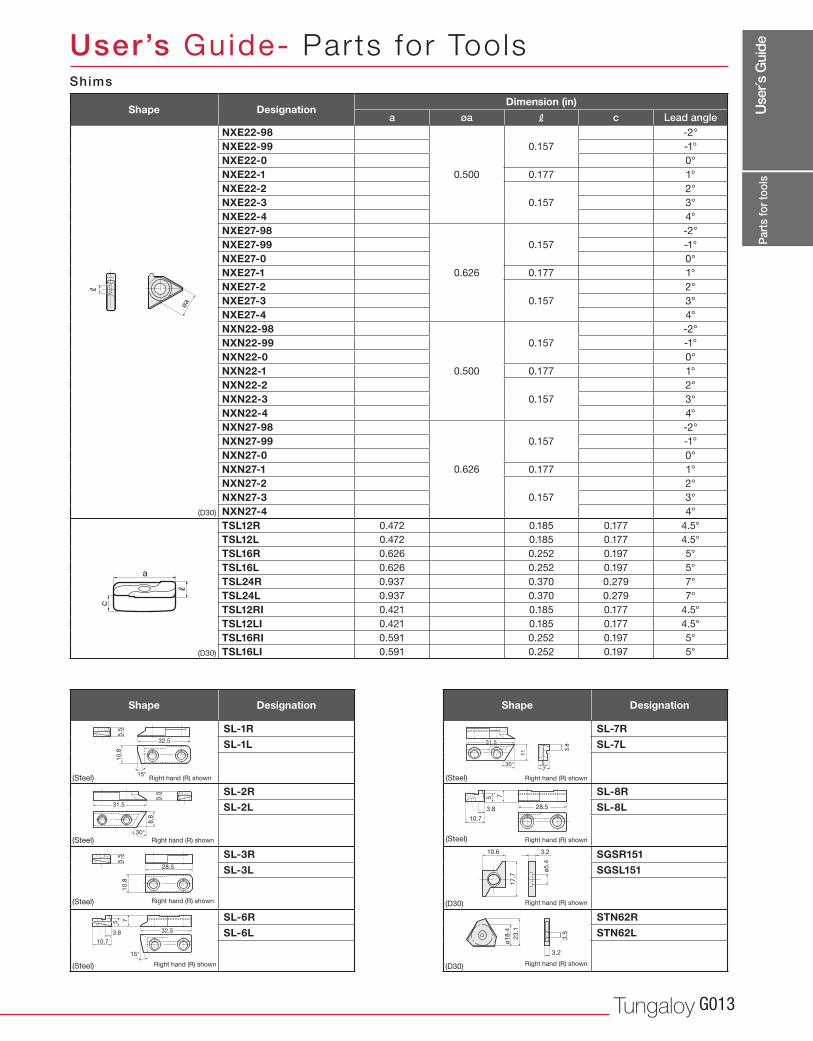
a øa R c
(D30)
NXE22-98
0.500
0.157
-2°
NXE22-99 -1°
NXE22-0 0°
NXE22-1 0.177 1°
NXE22-20.157
2°
NXE22-3 3°
NXE22-4 4°
NXE27-98
0.626
0.157
-2°
NXE27-99 -1°
NXE27-0 0°
NXE27-1 0.177 1°
NXE27-20.157
2°
NXE27-3 3°
NXE27-4 4°
NXN22-98
0.500
0.157
-2°
NXN22-99 -1°
NXN22-0 0°
NXN22-1 0.177 1°
NXN22-20.157
2°
NXN22-3 3°
NXN22-4 4°
NXN27-98
0.626
0.157
-2°
NXN27-99 -1°
NXN27-0 0°
NXN27-1 0.177 1°
NXN27-20.157
2°
NXN27-3 3°
NXN27-4 4°
(D30)
TSL12R 0.472 0.185 0.177 4.5°
TSL12L 0.472 0.185 0.177 4.5°
TSL16R 0.626 0.252 0.197 5°
TSL16L 0.626 0.252 0.197 5°
TSL24R 0.937 0.370 0.279 7°
TSL24L 0.937 0.370 0.279 7°
TSL12RI 0.421 0.185 0.177 4.5°
TSL12LI 0.421 0.185 0.177 4.5°
TSL16RI 0.591 0.252 0.197 5°
TSL16LI 0.591 0.252 0.197 5°
SL-1R
SL-1L
SL-2R
SL-2L
SL-3R
SL-3L
SL-6R
SL-6L
SL-7R
SL-7L
SL-8R
SL-8L
(D30)
SGSR151
SGSL151
(D30)
STN62R
STN62L
10.8
5.5
32.5
15°
8.8
5.5
31.5
30°
10
.85
.5
28.5
15°
10.7
75
3.8 32.5
R
øa
30°
11 3
.8
31.5
75
10.7
75
3.8 28.5
10.6 3.2
17.7
ø5.4
23.1
3.5
3.2
ø18.4
R
a
c
Part
s fo
r too
lsRight hand (R) shown
Right hand (R) shown
Right hand (R) shown
Right hand (R) shown
Right hand (R) shown
Right hand (R) shown
Right hand (R) shown
Right hand (R) shown
(Steel)
(Steel)
(Steel)
(Steel)
(Steel)
(Steel)
Shims
Shape DesignationDimension (in)
Lead angle
Shape Designation Shape Designation
User’s Guide- Parts for Tools
Use
r´s G
uide
www.tungaloyamerica.comG014
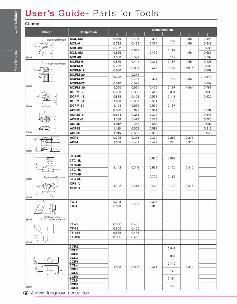
a b c d e R
MCL-5M 0.579 0.433 0.3070.157
M5 0.425
MCL-6 0.732 0.453 0.374 M6 0.543
MCL-8S 0.7520.531
0.4290.197
M8
0.535
MCL-8M 0.886 0.669
MCL-8L 1.000 0.571 0.157 0.787
MCPM-6 0.579 0.441 0.311 0.157 M5 0.425
MCPM-9 0.7520.661 0.429 0.197 M8×1
0.535
MCPM-12 0.886 0.669
MCPM-200.732
0.374
0.374 0.157 M60.543
MCPM-21 0.480
MCPM-22 0.846 0.520 0.657
MCPM-30 1.000 0.661 0.429 0.197 M8×1 0.787
DCPM-33 0.630 0.366 0.413 0.094 0.335
DCPM-43 0.835 0.453 0.531 0.118 0.520
DCPM-54 1.020 0.600 0.551 0.138
DCPM-64 1.104 0.610 0.630 0.157
ACP3S 0.898 0.375 0.394 0.591
ACP3S-E 0.854 0.375 0.394 0.547
ACP3L-E 1.038 0.472 0.512 0.723
ACP4S 1.012 0.472 0.512 0.697
ACP5S 1.185 0.508 0.591 0.815
ACP6S 1.315 0.508 0.650 0.945
ACP3 0.705 0.315 0.394 0.256 0.248
ACP4 1.000 0.439 0.472 0.276 0.315
CTC-3R
1.142 0.346
0.630 0.087
0.315
CTC-3L
CTC-4R0.669 0.126
CTC-4L
CTC-5R0.709 0.165
CTC-5L
CP81A1.102 0.413 0.472 0.138 0.315
CP81B
TC-3 0.7480.492
0.327- - -
TC-4 0.850 0.315
TF-72 0.866 0.455
TF-73 0.866 0.455
TF-184 0.866 0.455
TF-185 0.866 0.455
CCR2
1.366 0.587 0.421
0.047
0.413
CCL2CCR3
0.087CCL3CCR4
0.110CCL4CCR5
0.126CCL5CCR6
0.154CCL6CCR8
0.193CCL8
cd
b
a
R
cd
R
b
a
d
R
cb
a
de
cb
a
c
ed
b
a
de
cb
a
b
c
a
cd
e
b
a
a
bc
R
b
a
Part
s fo
r too
ls
e (Left-hand thread)
e (Left-hand thread)
Right hand (R) shown
TC-3 type shown, TC-4 : Left-hand thread
Clamps
Shape DesignationDimension (in)
User’s Guide- Parts for Tools
(Steel)
(Steel)
(Steel)
(Steel)
(Steel)
(Steel)
(Steel)
(Steel)
(Steel)
(Steel)
Use
r´s G
uide
Tungaloy G015
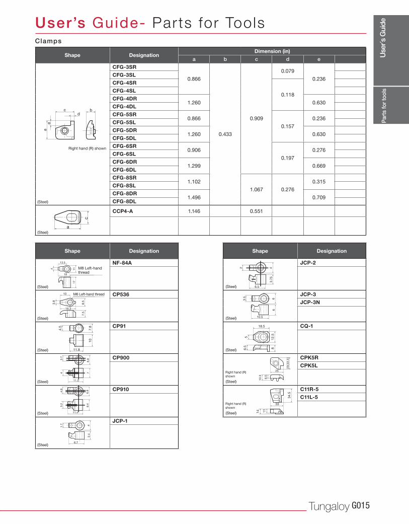
a b c d e
CFG-3SR
0.866
0.433
0.909
0.079
0.236CFG-3SL
CFG-4SR
0.118CFG-4SL
CFG-4DR1.260 0.630
CFG-4DL
CFG-5SR0.866
0.157
0.236CFG-5SL
CFG-5DR1.260 0.630
CFG-5DL
CFG-6SR0.906
0.197
0.276CFG-6SL
CFG-6DR1.299 0.669
CFG-6DL
CFG-8SR1.102
1.067 0.276
0.315CFG-8SL
CFG-8DR1.496 0.709
CFG-8DL
CCP4-A 1.146 0.551
NF-84A
CP536
CP91
CP900
CP910
JCP-1
JCP-2
JCP-3
JCP-3N
CQ-1
CPK5R
CPK5L
C11R-5
C11L-5
bc
ae
d
114
17
19
13.5
8.5
3.8
7.5
10
16.3
4.5
7.8
10
11.8
1.7 4
3.4
6.7
2 43.7
5
6.5
3.5 6
6
10.5
56
.5 81
2.5
18.5
25
23 2
2.3
6.5
10.3
33
34
.5
11
14
3.7
6.8
7
11.0
44.8
6.8
8.4
11.4
5.2
c
a
Part
s fo
r too
ls
M8 Left-hand thread
M6 Left-hand thread
Right hand (R)
shown
Right hand (R)
shown
Right hand (R) shown
Clamps
Shape DesignationDimension (in)
Shape Designation Shape Designation
User’s Guide- Parts for Tools
(Steel)
(Steel)
(Steel)
(Steel)
(Steel)
(Steel)
(Steel)
(Steel)
(Steel)
(Steel)
(Steel)
(Steel)
(Steel)
Use
r´s G
uide
www.tungaloyamerica.comG016
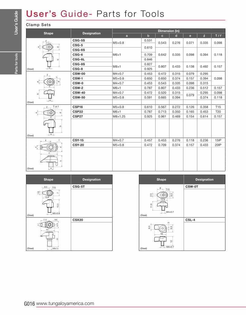
a b c d e R T / f
CSG-5SM5×0.8
0.5310.543 0.276 0.071 0.335 0.098
CSG-50.610
CSG-6S
M6×1 0.642 0.335 0.098 0.394 0.118CSG-6 0.709
CSG-6L 0.846
CSG-8SM8×1
0.8270.807 0.433 0.138 0.492 0.157
CSG-8 0.925
CSW-00 M4×0.7 0.453 0.472 0.315 0.079 0.295
0.098CSW-1 M5×0.8 0.650 0.650 0.374 0.157 0.394
CSW-0 M4×0.7 0.453 0.543 0.335 0.098 0.315
CSW-2 M6×1 0.787 0.807 0.433 0.236 0.512 0.157
CSW-40 M4×0.7 0.472 0.520 0.3150.079
0.295 0.098
CSW-50 M5×0.8 0.591 0.665 0.394 0.374 0.118
CSP16 M5×0.8 0.610 0.567 0.272 0.126 0.358 T15
CSP22 M6×1 0.787 0.713 0.350 0.165 0.453 T20
CSP27 M8×1.25 0.925 0.961 0.469 0.154 0.614 0.157
CSY-15 M4×0.7 0.457 0.453 0.276 0.118 0.236 15IP
CSY-20 M5×0.8 0.472 0.709 0.374 0.157 0.433 20IP
CSG-5T
CSX20
CSW-0T
CSL-4
de
b
a
c
Rf
e df
b
a
c
R
e db
a
c
R
a
b
c
d
T
e
T20
M6x1.0
20
18.1
8.7
5
4.1
11.5
71.8
15
.5
M5×0.8
13.8
8.5 T15
M4×0.7
T15
2.5
8.5
11
.8
13.8
8
M4×0.7
6.5
9.5
12
16
3
Part
s fo
r too
ls
T or f
Clamp Sets
Shape DesignationDimension (in)
Shape Designation Shape Designation
User’s Guide- Parts for Tools
(Steel)
(Steel)
(Steel)
(Steel)
(Steel)
(Steel)
(Steel)
(Steel)
Use
r´s G
uide
Tungaloy G017
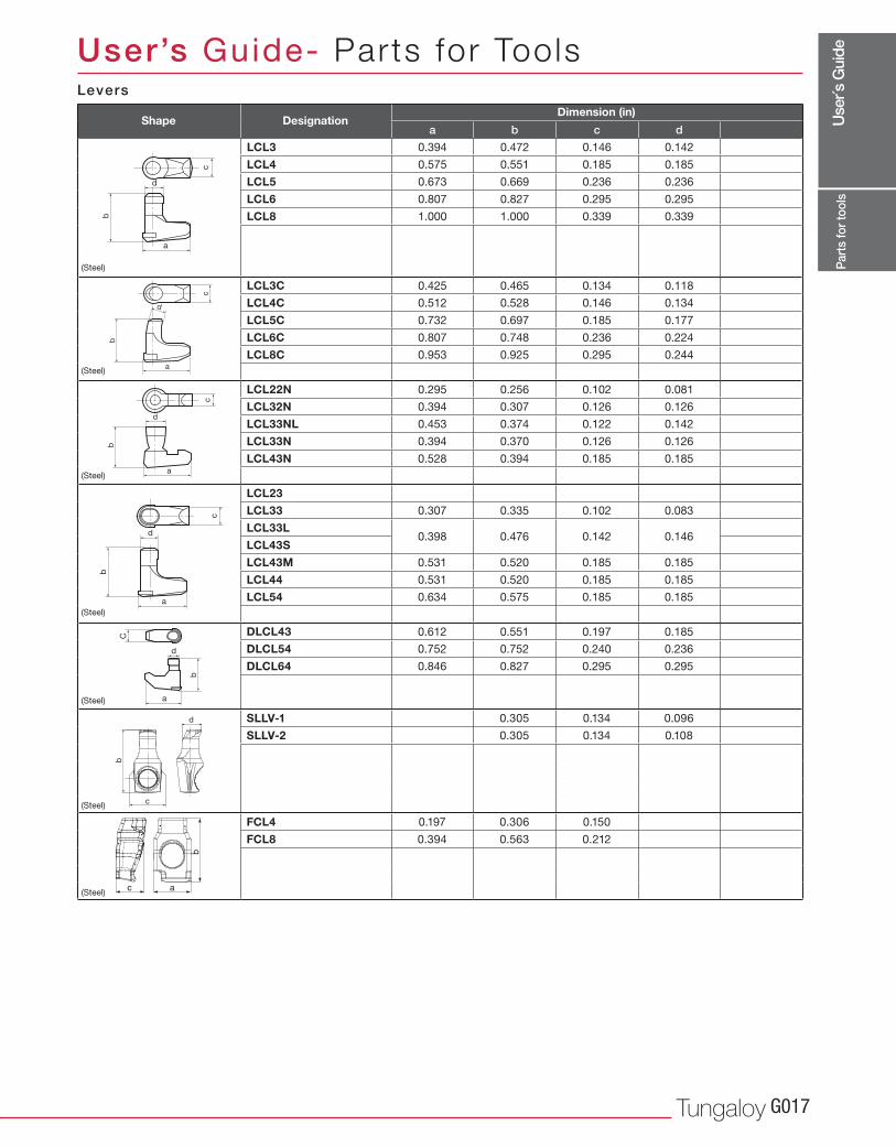
a b c d
LCL3 0.394 0.472 0.146 0.142
LCL4 0.575 0.551 0.185 0.185
LCL5 0.673 0.669 0.236 0.236
LCL6 0.807 0.827 0.295 0.295
LCL8 1.000 1.000 0.339 0.339
LCL3C 0.425 0.465 0.134 0.118
LCL4C 0.512 0.528 0.146 0.134
LCL5C 0.732 0.697 0.185 0.177
LCL6C 0.807 0.748 0.236 0.224
LCL8C 0.953 0.925 0.295 0.244
LCL22N 0.295 0.256 0.102 0.081
LCL32N 0.394 0.307 0.126 0.126
LCL33NL 0.453 0.374 0.122 0.142
LCL33N 0.394 0.370 0.126 0.126
LCL43N 0.528 0.394 0.185 0.185
LCL23 0.307 0.335 0.102 0.083
LCL33 0.307 0.335 0.102 0.083
LCL33L0.398 0.476 0.142 0.146
LCL43S 0.142
LCL43M 0.531 0.520 0.185 0.185
LCL44 0.531 0.520 0.185 0.185
LCL54 0.634 0.575 0.185 0.185
0.650 0.677 0.240 0.236
DLCL43 0.612 0.551 0.197 0.185
DLCL54 0.752 0.752 0.240 0.236
DLCL64 0.846 0.827 0.295 0.295
SLLV-1 0.305 0.134 0.096
SLLV-2 0.305 0.134 0.108
FCL4 0.197 0.306 0.150
FCL8 0.394 0.563 0.212
c
b
d
a
c
b
d
a
d
c
b
a
d
c
b
a
C
b
a
d
d
b
c
c
b
a
Part
s fo
r too
ls
Levers
Shape DesignationDimension (in)
User’s Guide- Parts for Tools
(Steel)
(Steel)
(Steel)
(Steel)
(Steel)
(Steel)
(Steel)
Use
r´s G
uide
www.tungaloyamerica.comG018
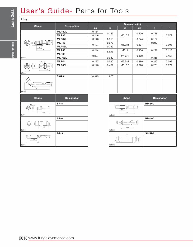
øa b øc ød e f
MLP32L 0.1540.346
M5×0.80.220 0.138
0.079MLP33 0.146
MLP34L 0.146 0.516 0.244 0.197
MLP460.197
0.677M6.3×1 0.307
0.2170.098
MLP46L 0.732
0.272MLP58 0.2440.862
M8×1 0.406 0.118
MLP680.307 M10×1 0.469 0.157
MLP68L 0.949 0.358
MLP44 0.197 0.520 M6.3×1 0.280 0.217 0.098
MLP33L 0.146 0.409 M5×0.8 0.220 0.201 0.079
SW99 0.315 1.870
SP-8
SP-6
BP-3
BP-360
BP-490
SL-PI-2
cøa
ød
b
f e
cøa
ød
e
bf
b
øa
M5×0.8
ø8.0
25.0
ø6.0
ø6.0
14.0
ø3.8
ø3.6
19.0
6.0
ø3
.8
ø3
.6
19.0
6.0
ø4
.8
ø3
.6
15.5
ø2
ø2
.3
7
Part
s fo
r too
ls
P ins
Shape DesignationDimension (in)
Shape Designation Shape Designation
User’s Guide- Parts for Tools
(Steel)
(Steel)
(Steel)
(Steel)
(Steel)
(Steel)
(Steel)
(Steel)
(Steel)
Use
r´s G
uide
Tungaloy G019
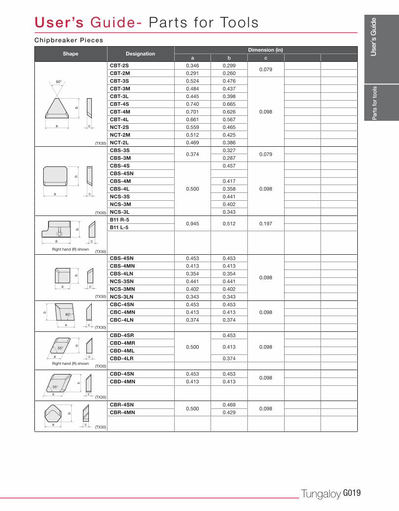
a b c
CBT-2S 0.346 0.2990.079
CBT-2M 0.291 0.260
CBT-3S 0.524 0.476
0.098
CBT-3M 0.484 0.437
CBT-3L 0.445 0.398
CBT-4S 0.740 0.665
CBT-4M 0.701 0.626
CBT-4L 0.661 0.567
NCT-2S 0.559 0.465
NCT-2M 0.512 0.425
NCT-2L 0.469 0.386
CBS-3S0.374
0.3270.079
CBS-3M 0.287
CBS-4S
0.500
0.457
0.098
CBS-4SN
CBS-4M 0.417
CBS-4L 0.358
NCS-3S 0.441
NCS-3M 0.402
NCS-3L 0.343
B11 R-50.945 0.512 0.197
B11 L-5
CBS-4SN 0.453 0.453
0.098
CBS-4MN 0.413 0.413
CBS-4LN 0.354 0.354
NCS-3SN 0.441 0.441
NCS-3MN 0.402 0.402
NCS-3LN 0.343 0.343
CBC-4SN 0.453 0.453
0.098CBC-4MN 0.413 0.413
CBC-4LN 0.374 0.374
CBD-4SR
0.500
0.453
0.098CBD-4MR
0.413CBD-4ML
CBD-4LR 0.374
CBD-4SN 0.453 0.4530.098
CBD-4MN 0.413 0.413
CBR-4SN0.500
0.4690.098
CBR-4MN 0.429
b
a c
60°
b
a c
b
a c
b
a c
b
a c
80°
b
a c
55°
b
a c
55°
b
a c
(TX30)
(TX30)
(TX30)
(TX30)
(TX30)
(TX30)
(TX30)
(TX30)
Part
s fo
r too
ls
Right hand (R) shown
Right hand (R) shown
Chipbreaker Pieces
Shape DesignationDimension (in)
User’s Guide- Parts for Tools
Use
r´s G
uide
www.tungaloyamerica.comG020
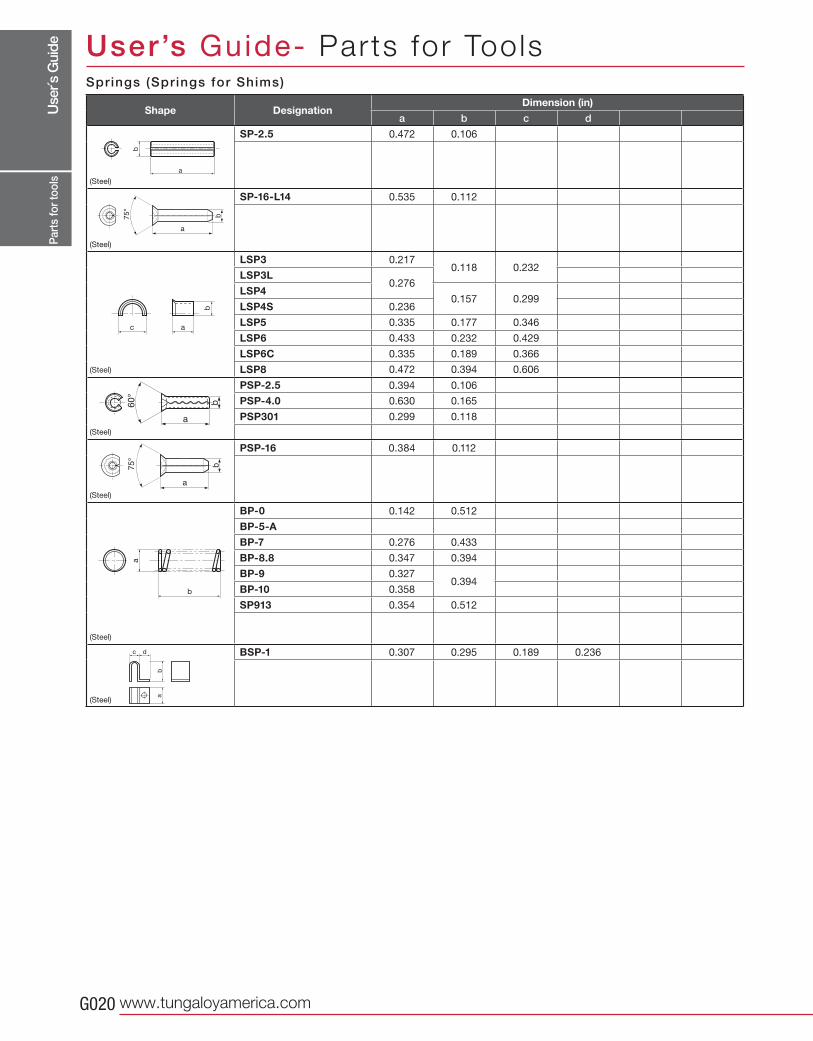
a b c d
SP-2.5 0.472 0.106
w
SP-16-L14 0.535 0.112
w
LSP3 0.2170.118 0.232
LSP3L0.276
LSP40.157 0.299
LSP4S 0.236
LSP5 0.335 0.177 0.346
LSP6 0.433 0.232 0.429
LSP6C 0.335 0.189 0.366
LSP8 0.472 0.394 0.606
PSP-2.5 0.394 0.106
PSP-4.0 0.630 0.165
PSP301 0.299 0.118
PSP-16 0.384 0.112
BP-0 0.142 0.512
BP-5-A
BP-7 0.276 0.433
BP-8.8 0.347 0.394
BP-9 0.3270.394
BP-10 0.358
SP913 0.354 0.512
BSP-1 0.307 0.295 0.189 0.236
b
c a
b
a
ba
c d
a
b
Part
s fo
r too
ls
Spr ings (Springs for Shims)
Shape DesignationDimension (in)
User’s Guide- Parts for Tools
(Steel)
(Steel)
(Steel)
(Steel)
(Steel)
(Steel)
(Steel)
Use
r´s G
uide
Tungaloy G021
a øb
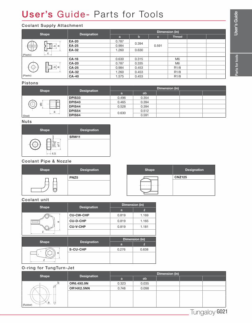
OR6.4X0.9N 0.323 0.035
OR14X2.5NN 0.748 0.098
a b cEA-20 0.787
0.3940.591EA-25 0.984
EA-32 1.260 0.630
CA-16 0.630 0.315 M6
CA-20 0.787 0.335 M6
CA-25 0.984 0.453 R1/8
CA-32 1.260 0.453 R1/8
CA-40 1.575 0.453 R1/8
a øbDPIS33 0.496 0.354
DPIS43 0.465 0.394
DPIS44 0.528 0.394
DPIS540.630
0.512
DPIS64 0.591
SRW11
PNZ5
CNZ125
bc
a
b a
øb
a
4.5
ø11
a
b
a R
CU-CW-CHP 0.819 1.169
CU-D-CHP 0.819 1.165
CU-V-CHP 0.819 1.181
a R
S-CU-CHP 0.276 0.638
a
R
a
R
Part
s fo
r too
ls
Nuts
M6
Left
-han
d
thre
ad
Coolant Supply Attachment
Pistons
Shape DesignationDimension (in)
Thread
Shape DesignationDimension (in)
Shape Designation
Shape Designation Stock Shape Designation Stock
O-ring for TungTurn-Jet
Shape DesignationDimension (in)
Coolant unit
Shape DesignationDimension (in)
Shape DesignationDimension (in)
User’s Guide- Parts for Tools
Coolant Pipe & Nozzle
(Plastic)
(Plastic)
(Steel)
(Rubber)
Use
r´s G
uide
www.tungaloyamerica.comG022
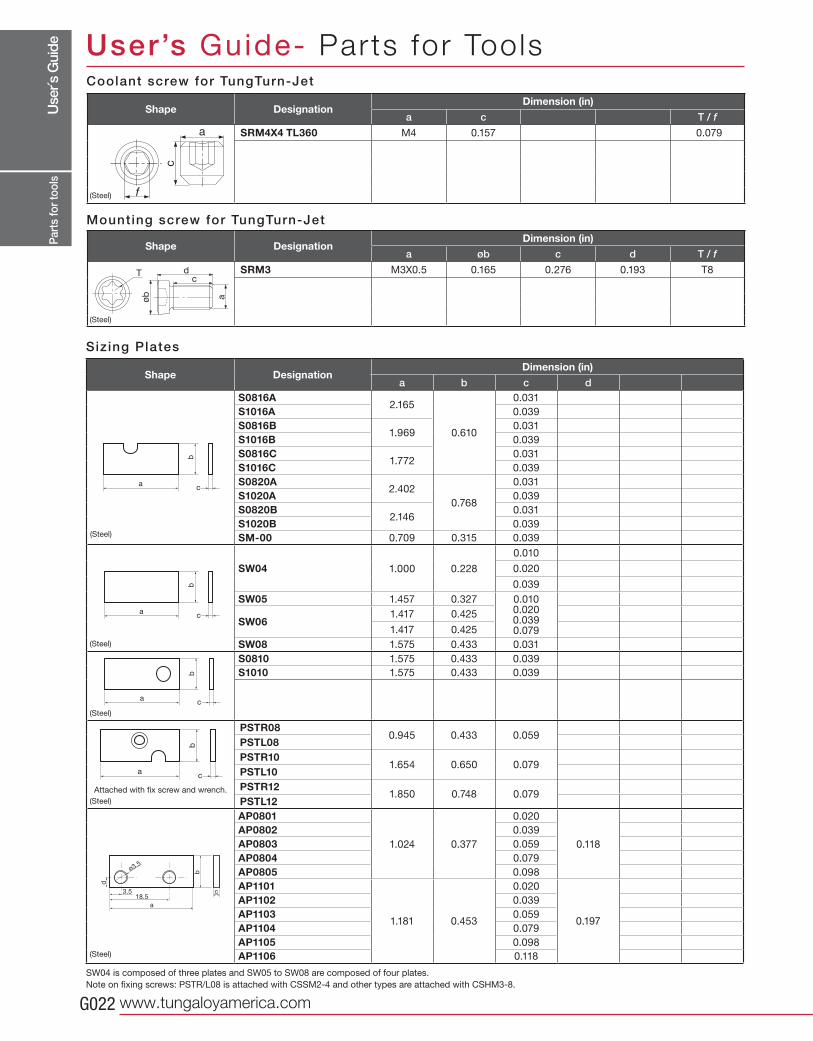
a b c dS0816A
2.165
0.610
0.031
S1016A 0.039
S0816B1.969
0.031
S1016B 0.039
S0816C1.772
0.031
S1016C 0.039
S0820A2.402
0.768
0.031
S1020A 0.039
S0820B2.146
0.031
S1020B 0.039
SM-00 0.709 0.315 0.039
SW04 1.000 0.228
0.010
0.020
0.039
SW05 1.457 0.327 0.0100.0200.0390.079
SW061.417 0.425
1.417 0.425
SW08 1.575 0.433 0.031
S0810 1.575 0.433 0.039
S1010 1.575 0.433 0.039
PSTR080.945 0.433 0.059
PSTL08PSTR10
1.654 0.650 0.079PSTL10PSTR12
1.850 0.748 0.079PSTL12AP0801
1.024 0.377
0.020
0.118
AP0802 0.039
AP0803 0.059
AP0804 0.079
AP0805 0.098
AP1101
1.181 0.453
0.020
0.197
AP1102 0.039
AP1103 0.059
AP1104 0.079
AP1105 0.098
AP1106 0.118
b
ac
b
ac
b
ac
b
ac
b
d
a
c18.5
3.5
ø3.5
a c T / f
SRM4X4 TL360 M4 0.157 0.079
a øb c d T / f
SRM3 M3X0.5 0.165 0.276 0.193 T8
a
dc
T
øb
f
a
c
Part
s fo
r too
ls
SW04 is composed of three plates and SW05 to SW08 are composed of four plates.
Note on fixing screws: PSTR/L08 is attached with CSSM2-4 and other types are attached with CSHM3-8.
Attached with fix screw and wrench.
Shape DesignationDimension (in)
Coolant screw for TungTurn-Jet
Shape DesignationDimension (in)
Mounting screw for TungTurn-Jet
Shape DesignationDimension (in)
User’s Guide- Parts for Tools
(Steel)
(Steel)
(Steel)
(Steel)
(Steel)
(Steel)
(Steel)
Sizing Plates
Use
r´s G
uide
Tungaloy G023
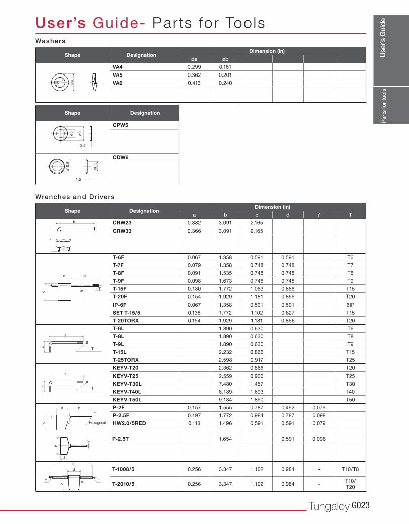
øa øb
VA4 0.299 0.161
VA5 0.362 0.201
VA6 0.413 0.240
CPW5
CDW6
a b c d f T
CRW23 0.382 3.091 2.165
CRW33 0.366 3.091 2.165
T-6F 0.067 1.358 0.591 0.591 T6
T-7F 0.079 1.358 0.748 0.748 T7
T-8F 0.091 1.535 0.748 0.748 T8
T-9F 0.098 1.673 0.748 0.748 T9
T-15F 0.130 1.772 1.063 0.866 T15
T-20F 0.154 1.929 1.181 0.866 T20
IP-6F 0.067 1.358 0.591 0.591 6IP
SET T-15/5 0.138 1.772 1.102 0.827 T15
T-20TORX 0.154 1.929 1.181 0.866 T20
T-6L 1.890 0.630 T6
T-8L 1.890 0.630 T8
T-9L 1.890 0.630 T9
T-15L 2.232 0.866 T15
T-25TORX 2.598 0.917 T25
KEYV-T20 2.362 0.866 T20
KEYV-T25 2.559 0.906 T25
KEYV-T30L 7.480 1.457 T30
KEYV-T40L 8.189 1.693 T40
KEYV-T50L 9.134 1.890 T50
P-2F 0.157 1.555 0.787 0.492 0.079
P-2.5F 0.197 1.772 0.984 0.787 0.098
HW2.0/5RED 0.118 1.496 0.591 0.591 0.079
P-2.5T 1.654 0.591 0.098
T-1008/5 0.256 3.347 1.102 0.984 - T10/T8
T-2010/5 0.256 3.347 1.102 0.984 -T10/T20
øaøb
0.5
ø9
ø5
1.5
ø10.8
ø6.5
a
d b
c
T
b
c
a
f
d b
c
f
d
b
b
c
b
d
a TT
c
T
T
b
a
c
Part
s fo
r too
ls
Hexagonal
Washers
Wrenches and Drivers
Shape DesignationDimension (in)
Shape Designation
Shape DesignationDimension (in)
User’s Guide- Parts for Tools
Use
r´s G
uide
www.tungaloyamerica.comG024
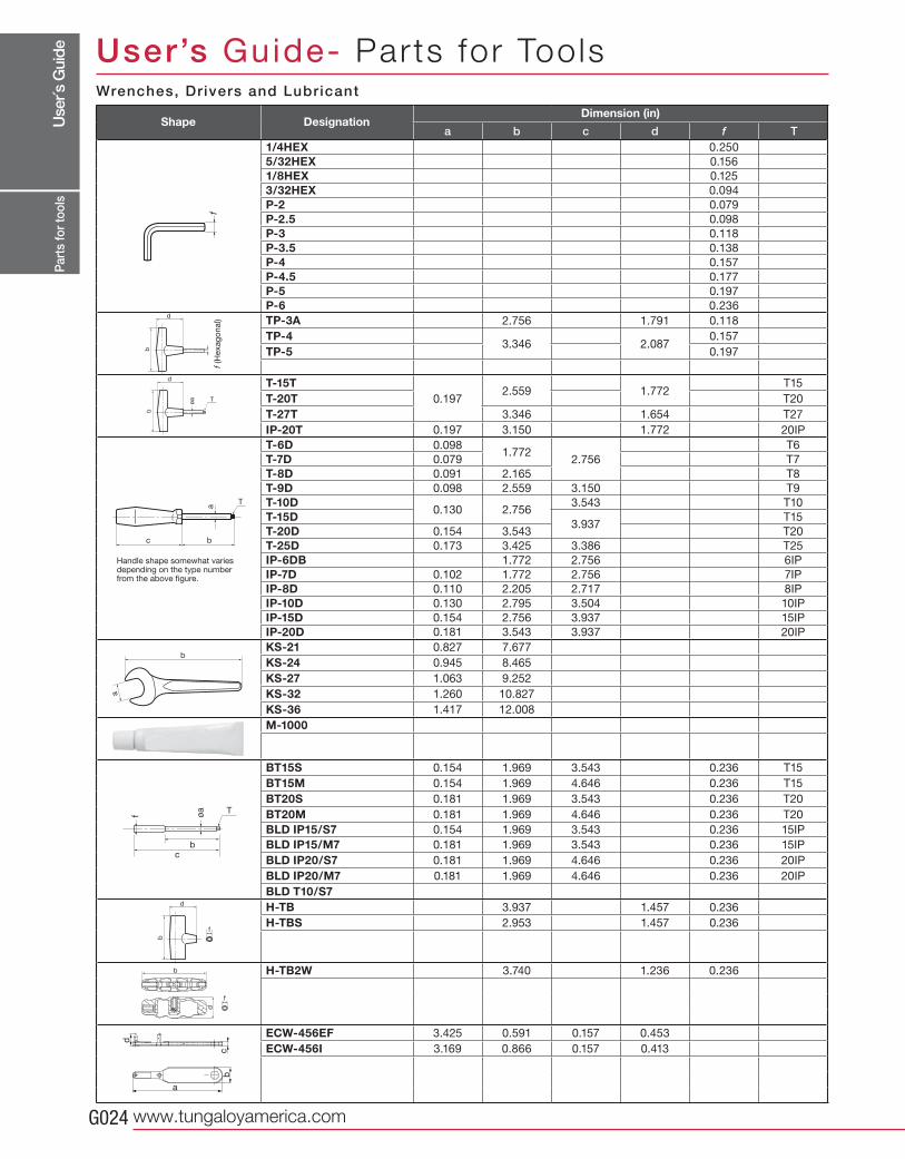
a b c d f T1/4HEX 0.250
5/32HEX 0.156
1/8HEX 0.125
3/32HEX 0.094
P-2 0.079
P-2.5 0.098
P-3 0.118
P-3.5 0.138
P-4 0.157
P-4.5 0.177
P-5 0.197
P-6 0.236
TP-3A 2.756 1.791 0.118
TP-43.346 2.087
0.157
TP-5 0.197
T-15T0.197
2.559 1.772T15
T-20T T20
T-27T 3.346 1.654 T27
IP-20T 0.197 3.150 1.772 20IP
T-6D 0.0981.772
2.756
T6
T-7D 0.079 T7
T-8D 0.091 2.165 T8
T-9D 0.098 2.559 3.150 T9
T-10D0.130 2.756
3.543 T10
T-15D3.937
T15
T-20D 0.154 3.543 T20
T-25D 0.173 3.425 3.386 T25
IP-6DB 1.772 2.756 6IP
IP-7D 0.102 1.772 2.756 7IP
IP-8D 0.110 2.205 2.717 8IP
IP-10D 0.130 2.795 3.504 10IP
IP-15D 0.154 2.756 3.937 15IP
IP-20D 0.181 3.543 3.937 20IP
KS-21 0.827 7.677
KS-24 0.945 8.465
KS-27 1.063 9.252
KS-32 1.260 10.827
KS-36 1.417 12.008
M-1000
BT15S 0.154 1.969 3.543 0.236 T15
BT15M 0.154 1.969 4.646 0.236 T15
BT20S 0.181 1.969 3.543 0.236 T20
BT20M 0.181 1.969 4.646 0.236 T20
BLD IP15/S7 0.154 1.969 3.543 0.236 15IP
BLD IP15/M7 0.181 1.969 3.543 0.236 15IP
BLD IP20/S7 0.181 1.969 4.646 0.236 20IP
BLD IP20/M7 0.181 1.969 4.646 0.236 20IP
BLD T10/S7H-TB 3.937 1.457 0.236
H-TBS 2.953 1.457 0.236
H-TB2W 3.740 1.236 0.236
ECW-456EF 3.425 0.591 0.157 0.453
ECW-456I 3.169 0.866 0.157 0.413
b
d
f
a
bc
d
d
b
øa
d
T
b
a
bc
T
b
a
f
d
f
b
bc
øa
f
T
Part
s fo
r too
ls
f (H
exag
onal)
Handle shape somewhat varies depending on the type number from the above figure.
Wrenches, Drivers and Lubricant
Shape DesignationDimension (in)
User’s Guide- Parts for Tools
Use
r´s G
uide
Tungaloy G025
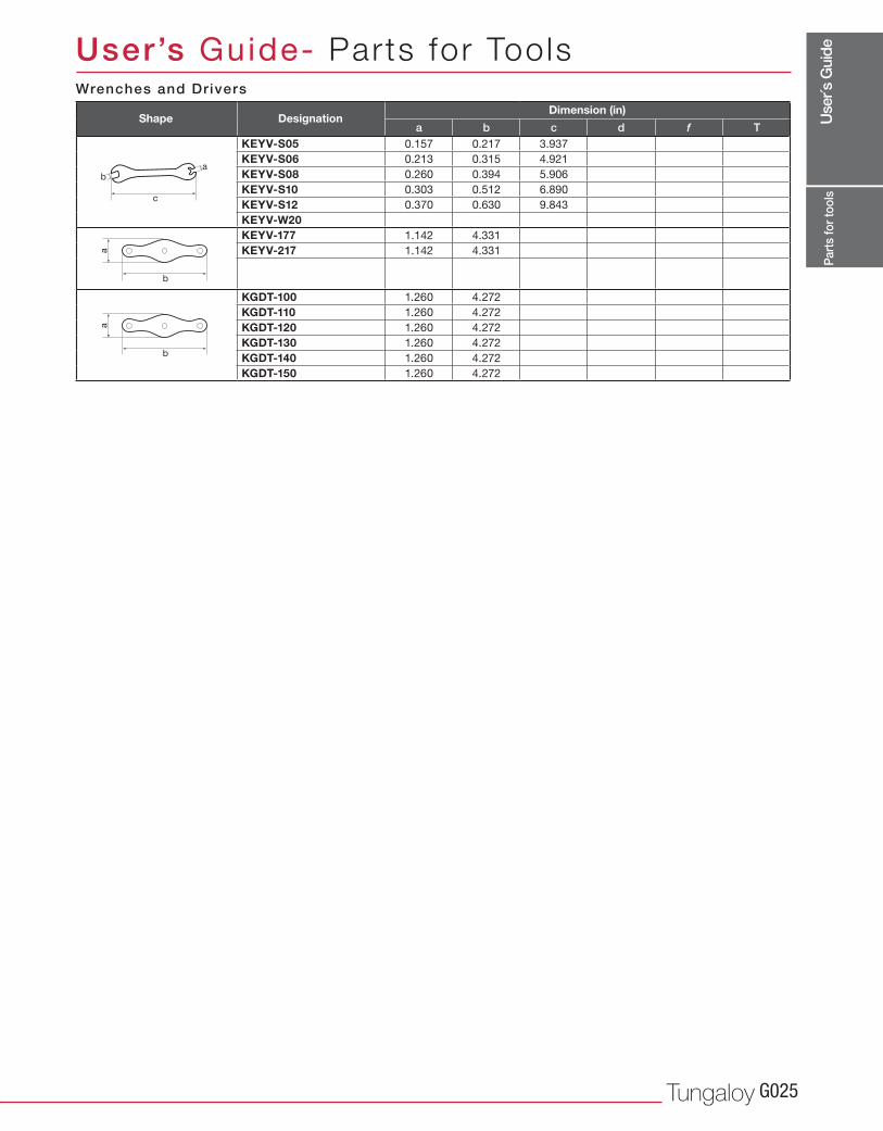
a b c d f TKEYV-S05 0.157 0.217 3.937
KEYV-S06 0.213 0.315 4.921
KEYV-S08 0.260 0.394 5.906
KEYV-S10 0.303 0.512 6.890
KEYV-S12 0.370 0.630 9.843
KEYV-W20KEYV-177 1.142 4.331
KEYV-217 1.142 4.331
KGDT-100 1.260 4.272
KGDT-110 1.260 4.272
KGDT-120 1.260 4.272
KGDT-130 1.260 4.272
KGDT-140 1.260 4.272
KGDT-150 1.260 4.272
c
ba
b
a
b
a
Part
s fo
r too
ls
Wrenches and Drivers
Shape DesignationDimension (in)
User’s Guide- Parts for Tools
Use
r´s G
uide
www.tungaloyamerica.comG026
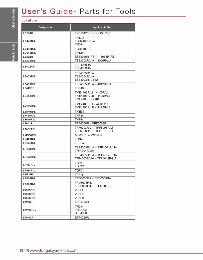
LD150R
LD440R/L
LD442R/L
LD540R/L
LE302R
LE303R/L
LE402AR
LE403R/L
LE405R/L
LE413R/L
LE444R/L
LE446R/L
LE540R/L
LF440R/L
LF540R/L
LF602R
LF602R/L
LMS56R/L
LN423R/L
LN645R/L
LP403R/L
LP405R/L
LP413R/L
LP514R/L
LPP16R
LR602R/L
LR603R/L
LV525R/L
LV530R/L
LV556R/L
LW400R
LW400R/L
LW402R
TXD15125R ~ TXD15315R
EGD4400R
TMD54
ESE3050R (RS**) ~ 3063R (RS**)
TSE3003R/LIA ~ 3006R/LIA
TSE4005R/LIA ~ 4012R/LIA
TME54
THF44
THF54
ERF6050R ~ ERF6063R
MS08R/L ~ MS12R/L
TGN42
TPN64
TGP51
TPP16
ERD6050RA ~ ERD6063RA
VSN 1
VSN 2
VSN60
EFP4063R
EFP4050R
THE40
ESE4050RAESE4063RA
TME4406R/LI ~ 4412R/LITME4406R/LB ~ 4412R/LB
TRF6003R/LI ~ TRF6006R/LITRF6008R/LI ~ TRF6012R/LI
TSP4003R/LIA ~ TSP4004R/LIATFP4004R/LIA
TSP4005R/LIA ~ TSP4012R/LIATFP4005R/LIA ~ TFP4012R/LIA
TRD6003R/LTRD6004R/L ~ TRD6008R/L
TGP41TGP42
TMD44TGD4400R/L-ATFD44
TSE4003R/LIATSE4004R/LIAESE4003RIA-S32
TME4403R/LI ~ 4405R/LITME4403R/LB ~ 4405R/LBEME4405R ~ 4404RI
TFD44TFP4000SFP4000
Part
s fo
r too
ls
Locators
Designation Applicable Tool
User’s Guide- Parts for Tools
Use
r´s G
uide
Tungaloy G027
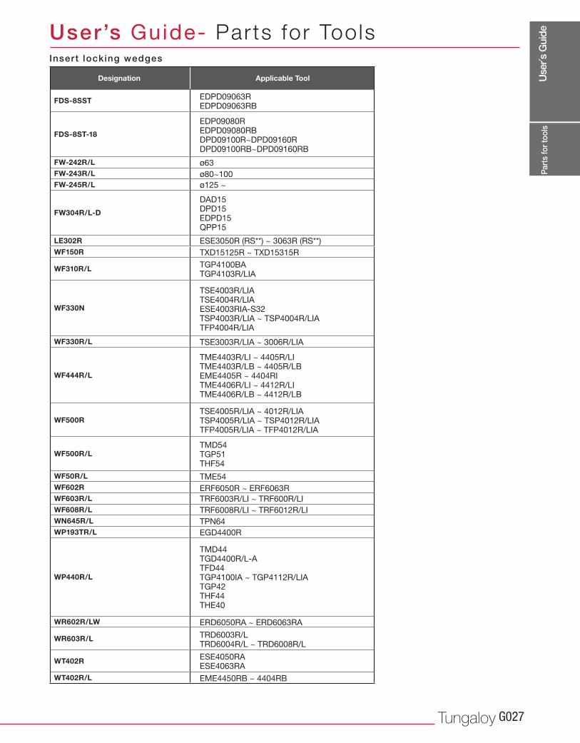
FDS-8SST
FDS-8ST-18
FW-242R/L
FW-243R/L
FW-245R/L
FW304R/L-D
LE302R
WF150R
WF310R/L
WF330N
WF330R/L
WF444R/L
WF500R
WF500R/L
WF50R/L
WF602R
WF603R/L
WF608R/L
WN645R/L
WP193TR/L
WP440R/L
WR602R/LW
WR603R/L
WT402R
WT402R/L
EDPD09063REDPD09063RB
TRD6003R/LTRD6004R/L ~ TRD6008R/L
ESE4050RAESE4063RA
TGP4100BATGP4103R/LIA
TSE4005R/LIA ~ 4012R/LIATSP4005R/LIA ~ TSP4012R/LIATFP4005R/LIA ~ TFP4012R/LIA
TMD54TGP51THF54
EDP09080REDPD09080RBDPD09100R~DPD09160RDPD09100RB~DPD09160RB
TSE4003R/LIATSE4004R/LIAESE4003RIA-S32TSP4003R/LIA ~ TSP4004R/LIATFP4004R/LIA
TME4403R/LI ~ 4405R/LITME4403R/LB ~ 4405R/LBEME4405R ~ 4404RITME4406R/LI ~ 4412R/LITME4406R/LB ~ 4412R/LB
TMD44TGD4400R/L-ATFD44TGP4100IA ~ TGP4112R/LIATGP42THF44THE40
DAD15DPD15EDPD15QPP15
ø63
ø80~100
ø125 ~
ESE3050R (RS**) ~ 3063R (RS**)
TSE3003R/LIA ~ 3006R/LIA
TME54
ERF6050R ~ ERF6063R
TRF6003R/LI ~ TRF600R/LI
TRF6008R/LI ~ TRF6012R/LI
TPN64
EGD4400R
ERD6050RA ~ ERD6063RA
EME4450RB ~ 4404RB
TXD15125R ~ TXD15315R
Part
s fo
r too
ls
Designation Applicable Tool
User’s Guide- Parts for ToolsInsert locking wedges
Use
r´s G
uide
www.tungaloyamerica.comG028
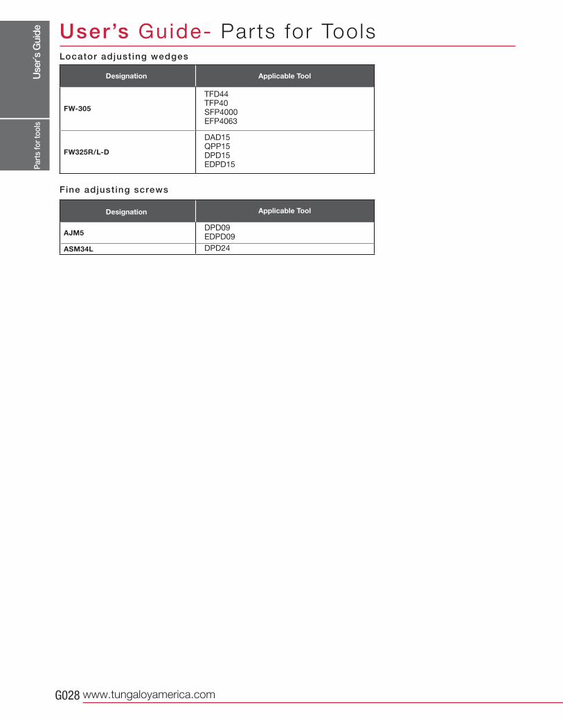
FW-305
FW325R/L-D
AJM5
ASM34L
TFD44TFP40SFP4000EFP4063
DAD15QPP15DPD15EDPD15
DPD09EDPD09
DPD24
Part
s fo
r too
ls
Designation
Designation
Locator adjust ing wedges
User’s Guide- Parts for Tools
Fine adjust ing screws
Applicable Tool
Applicable Tool
Use
r´s G
uide
Tungaloy G029
0° 15° 30°
Tec
hnic
alre
fere
nce
User’s Guide- Technica l Reference
k
f
h
ap
ae
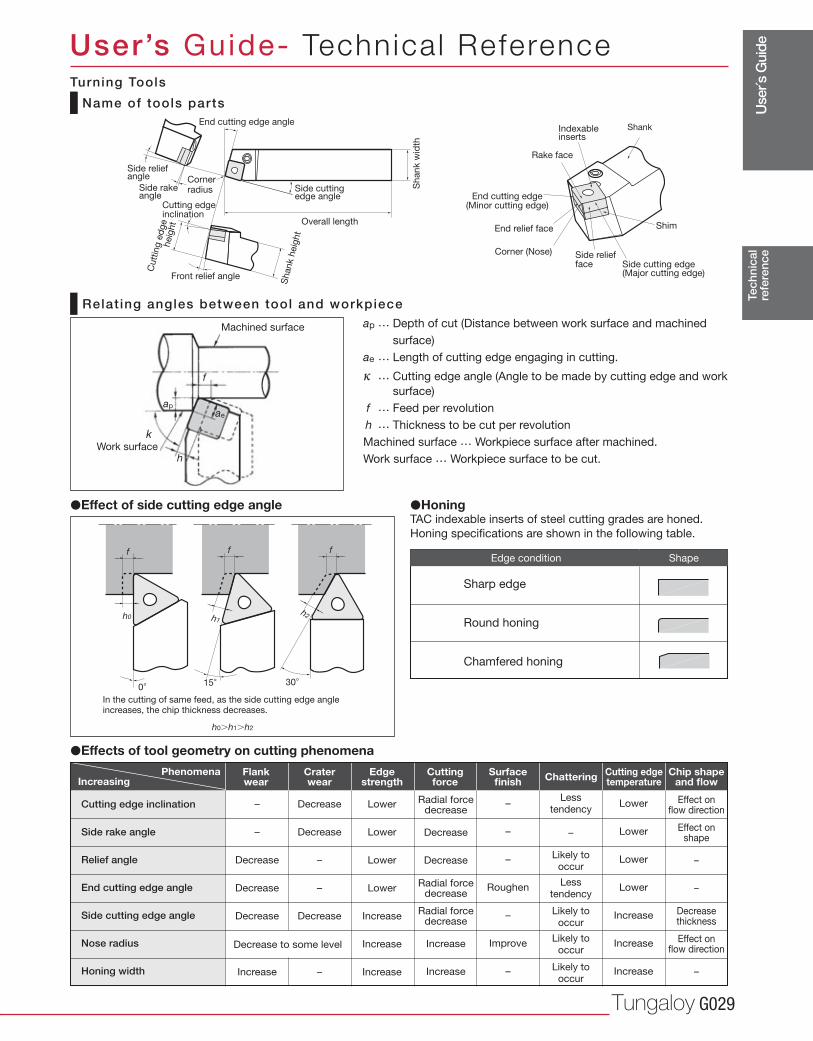
Name of tools parts
Relat ing angles between tool and workpiece ap … Depth of cut (Distance between work surface and machined
surface)
ae … Length of cutting edge engaging in cutting.
κ … Cutting edge angle (Angle to be made by cutting edge and work
surface)
f … Feed per revolution
h … Thickness to be cut per revolution
Machined surface … Workpiece surface after machined.
Work surface … Workpiece surface to be cut.
Machined surface
�Effect of side cutting edge angle �HoningTAC indexable inserts of steel cutting grades are honed.
Honing specifications are shown in the following table.
In the cutting of same feed, as the side cutting edge angle increases, the chip thickness decreases.
h0�h1�h2
End cutting edge angle
Sh
an
k w
idth
Side cutting edge angle
Overall length
Shank h
eig
ht
Cutt
ing e
dge
heig
ht
Side rakeangle
Side reliefangle Corner
radius
Cutting edgeinclination
Front relief angle
Indexableinserts
Shank
Rake face
ShimEnd relief face
End cutting edge(Minor cutting edge)
Corner (Nose) Side reliefface Side cutting edge
(Major cutting edge)
–
–
–
Roughen
–
Improve
–
Cutting edge inclination
Side rake angle
Relief angle
End cutting edge angle
Side cutting edge angle
Nose radius
Honing width
PhenomenaIncreasing
Flankwear
Edgestrength
Craterwear
Cuttingforce
Surfacefinish Chattering Cutting edge
temperature Chip shape
and flow
–
–
Decrease
Decrease
Decrease
Increase
Decrease
Decrease
–
–
Decrease
–
Lower
Lower
Lower
Lower
Increase
Increase
Increase
Radial forcedecrease
Decrease
Decrease
Radial forcedecrease
Radial forcedecrease
Increase
Increase
Less tendency
–
Likely to occur
Less tendency
Likely to occur
Likely to occur
Likely to occur
Lower
Lower
Lower
Lower
Increase
Increase
Increase
Effect onflow direction
Effect onshape
–
–
Decreasethickness
Effect onflow direction
–
Decrease to some level
Work surface
Turning Tools
Edge condition
Sharp edge
Round honing
Chamfered honing
Shape
�Effects of tool geometry on cutting phenomena
Use
r´s G
uide
www.tungaloyamerica.comG030
Tec
hnic
alre
fere
nce
User’s Guide- Technica l Reference
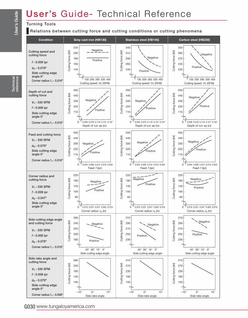
Relat ions between cutt ing force and cutt ing condit ions or cutt ing phenomena
Turning Tools
220
200
180
160
140
130 200 260 330 400 130 200 260 330 400 130 200 260 330 400
550
440
330
220
110
0
0
0.039 0.079 0.118 0.157 0.197
0.004 0.008 0.012 0.016 0.020 0.004 0.008 0.012 0.016 0.020 0.004 0.008 0.012 0.016 0.020
0.039 0.079 0.118 0.157 0.197 0.039 0.079 0.118 0.157 0.1970 0
550
440
330
220
110
550
440
330
220
110
550
440
330
220
110
220
180
140
100
60
220
180
140
100
60
220
180
140
100
60
45° 30° 15° 0°
220
180
140
100
−10° 0° 15°
340
315
290
265
240
320
295
270
245
220
0 0
45° 30° 15° 0°
270
230
190
−10° 0° 15°
0 0 0
310
290
270
250
230
310
290
270
250
230
260
240
220
200
180
45° 30° 15° 0°
270
260 310 310
230
190
150 150
−10° 0° 15°
0.016 0.031 0.047 0.063 0.079 0.016 0.031 0.047 0.063 0.079 0.016 0.031 0.047 0.063 0.079
550
440
330
220
110
550
440
330
220
110
Cutting speed andcutting force
f = 0.008 ipr
ap = 0.079"
Side cutting edge angle 0°Corner radius r ε = 0.016"
Depth of cut and cutting force
Vc = 330 SFM
f = 0.008 ipr
Side cutting edge angle 0°
Corner radius r ε = 0.016"
Feed and cutting force
Vc = 330 SFM
ap = 0.079"
Side cutting edge angle 0°
Corner radius r ε = 0.016"
Corner radius andcutting force
Vc = 330 SFM
f = 0.008 ipr
ap = 0.047"
Side cutting edge angle 0°
Side cutting edge angle and cutting force
Vc = 330 SFM
f = 0.008 ipr
ap = 0.079"
Corner radius r ε = 0.016"
Side rake angle and cutting force
Vc = 330 SFM
f = 0.008 ipr
ap = 0.079"
Side cutting edge angle 0°
Corner radius r ε = 0.008"
Grey cast iron (HB130) Stainless steel (HB145) Carbon steel (HB230)
Negative
Positive
Cutting speed: Vc (SFM) Cutting speed: Vc (SFM)
Cu
ttin
g f
orc
e (lb
f)
Cu
ttin
g f
orc
e (lb
f)
Cu
ttin
g f
orc
e (lb
f)
Negative
Positive
Negative
Positive
Depth of cut: ap (in) Depth of cut: ap (in) Depth of cut: ap (in)
Cu
ttin
g f
orc
e (lb
f)
Cu
ttin
g f
orc
e (lb
f)
Cu
ttin
g f
orc
e (lb
f)
Cu
ttin
g f
orc
e (lb
f)
Cu
ttin
g f
orc
e (lb
f)
Cu
ttin
g f
orc
e (lb
f)
Cu
ttin
g f
orc
e (lb
f)
Cu
ttin
g f
orc
e (lb
f)
Cu
ttin
g f
orc
e (lb
f)
Cu
ttin
g f
orc
e (lb
f)
Cu
ttin
g f
orc
e (lb
f)
Cu
ttin
g f
orc
e (lb
f)
Cu
ttin
g f
orc
e (lb
f)
Cu
ttin
g f
orc
e (lb
f)
Cu
ttin
g f
orc
e (lb
f)
Cutting speed: Vc (SFM)
Feed: f (ipr) Feed: f (ipr) Feed: f (ipr)
Corner radius: rε (in)Corner radius: rε (in)Corner radius: rε (in)
Side cutting edge angleSide cutting edge angle Side cutting edge angle
Side rake angle Side rake angle Side rake angle
Negative
Positive
Negative
Positive
Negative
Positive
Negative
Positive
Negative
Positive
Negative
Positive
Negative
Positive
Negative
Positive
Negative
Positive
Negative
Positive
Negative
Positive
Negative
Positive
Condition
Use
r´s G
uide
Tungaloy G031(HP) 33000
(μm)
T (min) 48
(min)T
Rf n
R
R
f
h
r ε
n
n
øD
øD
Tec
hnic
alre
fere
nce
User’s Guide- Technica l Reference
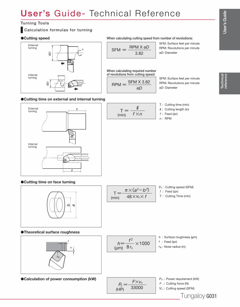
Calculat ion formulas for turning
�Calculation of power consumption (kW)
�Theoretical surface roughness
�Cutting time on face turning
When calculating cutting speed from number of revolutions:�Cutting speed
�Cutting time on external and internal turning
h : Surface roughness (μm)
f : Feed (ipr)
r ε : Nose radius (in)
Vc : Cutting speed (SFM)
f : Feed (ipr)
T : Cutting Time (min)
T : Cutting time (min)
R : Cutting length (in)
f : Feed (ipr)
n : RPM
Pc : Power requirement (kW)
F : Cutting force (N)
Vc : Cutting speed (SFM)
When calculating required numberof revolutions from cutting speed:
External turning
External turning
Internal turning
Internal turning
Turning Tools
RPM X øDSFM
3.82
SFM: Surface feet per minute
RPM: Revolutions per minute
øD: Diameter
SFM X 3.82RPM
øD
SFM: Surface feet per minute
RPM: Revolutions per minute
øD: Diameter
Use
r´s G
uide
www.tungaloyamerica.comG032
øDs
145
145
c
(HP) 33
r
( PSI )
( PSI )
( in )
( in )
56,565
85,572
113,855
142,137
255,992 ( 56HRC )
( 160HB )
( 200HB )
( 89HB )
100170230300
56HRC16020089
497612711782
1,21737048319615257157
41250658364099628437016412657157
35542649754885323630613810757157
3023634264707251942541179357157
247302348384598149194977557157
(lb-force)
Tec
hnic
alre
fere
nce
User’s Guide- Technica l Reference
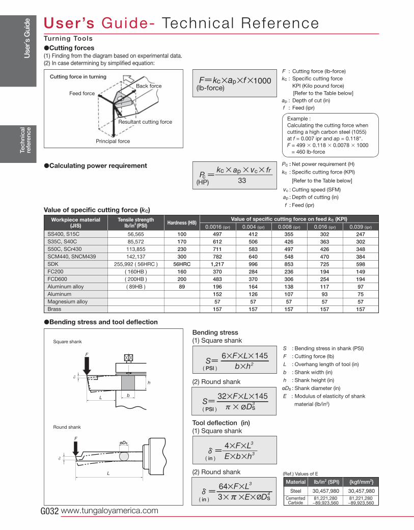
F : Cutting force (lb-force)
kc : Specific cutting force
KPI (Kilo pound force)
[Refer to the Table below]
ap : Depth of cut (in)
f : Feed (ipr)
Example :
Calculating the cutting force when
cutting a high carbon steel (1055)
at f = 0.007 ipr and ap = 0.118".
F = 499 � 0.118 � 0.0078 � 1000
= 460 lb-force
�Cutting forces(1) Finding from the diagram based on experimental data.
(2) In case determining by simplified equation:
Pc : Net power requirement (H)
kc : Specific cutting force (KPI)
[Refer to the Table below]
vc : Cutting speed (SFM)
ap : Depth of cutting (in)
f : Feed (ipr)
�Calculating power requirement
Principal force
Cutting force in turning
Feed force
�Bending stress and tool deflection
0.0016 (ipr) 0.004 (ipr) 0.008 (ipr) 0.016 (ipr) 0.039 (ipr)
Tensile strength lb/in2 (PSI)
SS400, S15C
S35C, S40C
S50C, SCr430
SCM440, SNCM439
SDK
FC200
FCD600
Aluminum alloy
Aluminum
Magnesium alloy
Brass
Workpiece material(JIS) Hardness (HB)
Value of specific cutting force on feed kc (KPI)
Bending stress(1) Square shank
(2) Round shank
Tool deflection (in)(1) Square shank
(2) Round shank
S : Bending stress in shank (PSI)
F : Cutting force (lb)
L : Overhang length of tool (in)
b : Shank width (in)
h : Shank height (in)
øDs : Shank diameter (in)
E : Modulus of elasticity of shank
material (lb/in2)
Square shank
Round shank
(Ref.) Values of E
Material lb/in2 (SPI) {kgf/mm2}
Steel 30,457,980 30,457,980
CementedCarbide
Resultant cutting force
Back force
Turning Tools
Value of specific cutting force (kc)
81,221,280 ~89,923,560
81,221,280 ~89,923,560
Use
r´s G
uide
Tungaloy G033
Tec
hnic
alre
fere
nce
User’s Guide- Technica l ReferenceF
laki
ngF
lank
wea
rC
rate
r w
ear
No
tch
wea
rF
ract
ure
Chi
pp
ing
Pla
stic
d
efo
rmat
ion
Chi
p w
eld
ing
The
rmal
cr
acki
ngB
uilt-
up e
dg
e
Countermeasure Tool grade Cutting conditions
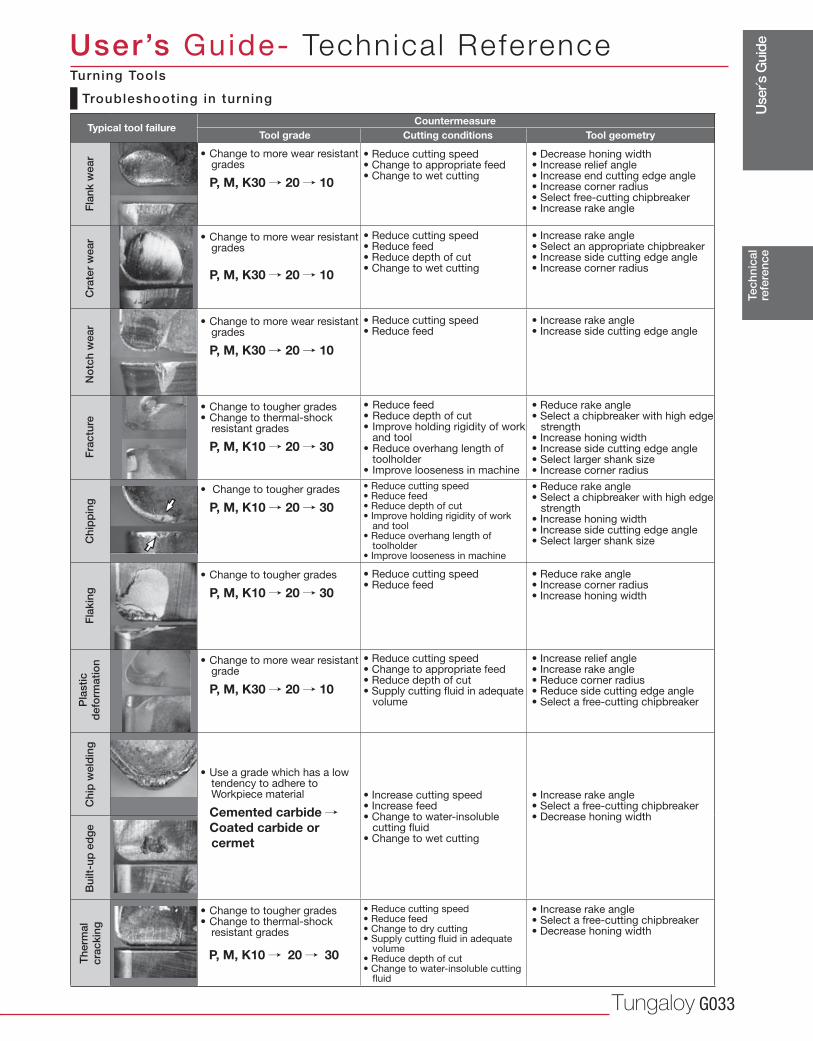
Troubleshooting in turning
• Change to more wear resistant grades
P, M, K30 / 20 / 10
• Reduce cutting speed• Change to appropriate feed• Change to wet cutting
• Decrease honing width• Increase relief angle• Increase end cutting edge angle• Increase corner radius• Select free-cutting chipbreaker• Increase rake angle
• Change to more wear resistant grades
P, M, K30 / 20 / 10
• Reduce cutting speed• Reduce feed• Reduce depth of cut• Change to wet cutting
• Increase rake angle• Select an appropriate chipbreaker• Increase side cutting edge angle• Increase corner radius
• Change to more wear resistant grades
P, M, K30 / 20 / 10
• Reduce cutting speed• Reduce feed
• Increase rake angle• Increase side cutting edge angle
• Change to tougher grades• Change to thermal-shock
resistant grades P, M, K10 / 20 / 30
• Reduce feed• Reduce depth of cut• Improve holding rigidity of work
and tool• Reduce overhang length of
toolholder• Improve looseness in machine
• Reduce rake angle• Select a chipbreaker with high edge
strength• Increase honing width• Increase side cutting edge angle• Select larger shank size• Increase corner radius
• Reduce cutting speed• Reduce feed• Reduce depth of cut• Improve holding rigidity of work
and tool• Reduce overhang length of
toolholder• Improve looseness in machine
• Reduce rake angle• Select a chipbreaker with high edge
strength• Increase honing width• Increase side cutting edge angle• Select larger shank size
• Reduce cutting speed• Reduce feed
• Reduce rake angle• Increase corner radius• Increase honing width
• Change to more wear resistant grade
P, M, K30 / 20 / 10
• Reduce cutting speed• Change to appropriate feed• Reduce depth of cut• Supply cutting fluid in adequate
volume
• Increase relief angle• Increase rake angle• Reduce corner radius• Reduce side cutting edge angle• Select a free-cutting chipbreaker
• Use a grade which has a low tendency to adhere to Workpiece material
Cemented carbide / Coated carbide or
cermet
• Increase cutting speed• Increase feed• Change to water-insoluble cutting fluid• Change to wet cutting
• Increase rake angle• Select a free-cutting chipbreaker• Decrease honing width
• Change to tougher grades• Change to thermal-shock
resistant grades
P, M, K10 / 20 / 30
• Reduce cutting speed• Reduce feed• Change to dry cutting• Supply cutting fluid in adequate
volume• Reduce depth of cut• Change to water-insoluble cutting
fluid
• Increase rake angle• Select a free-cutting chipbreaker• Decrease honing width
• Change to tougher grades P, M, K10 / 20 / 30
• Change to tougher grades P, M, K10 / 20 / 30
Turning Tools
Tool geometryTypical tool failure
Use
r´s G
uide
www.tungaloyamerica.comG034
Tec
hnic
alre
fere
nce
User’s Guide- Technica l Reference
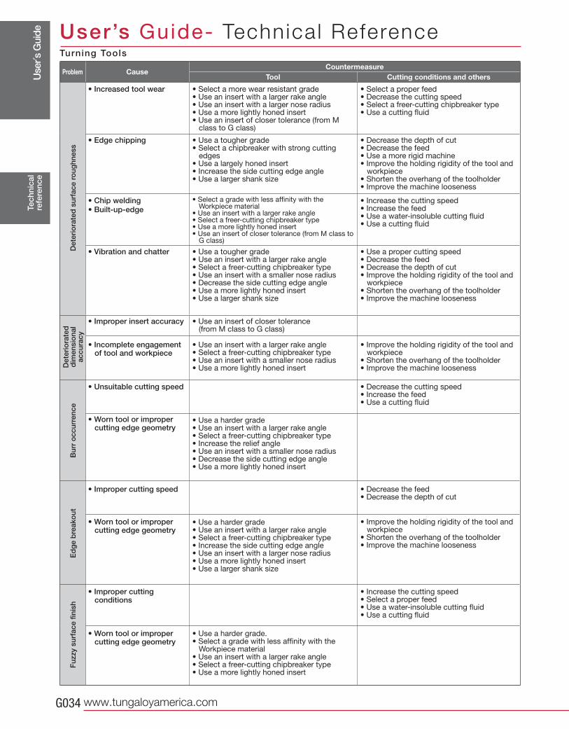
ProblemCountermeasure
ToolCause
Det
erio
rate
d s
urfa
ce r
oug
hnes
sD
eter
iora
ted
d
imen
sio
nal
accu
racy
Bur
r o
ccur
renc
eE
dg
e b
reak
out
Fuz
zy s
urfa
ce fi
nish
• Select a more wear resistant grade• Use an insert with a larger rake angle• Use an insert with a larger nose radius• Use a more lightly honed insert• Use an insert of closer tolerance (from M
class to G class)
• Increased tool wear • Select a proper feed• Decrease the cutting speed• Select a freer-cutting chipbreaker type• Use a cutting fluid
• Use a tougher grade• Select a chipbreaker with strong cutting
edges • Use a largely honed insert• Increase the side cutting edge angle• Use a larger shank size
• Edge chipping • Decrease the depth of cut• Decrease the feed• Use a more rigid machine• Improve the holding rigidity of the tool and
workpiece• Shorten the overhang of the toolholder• Improve the machine looseness
• Select a grade with less affinity with the Workpiece material
• Use an insert with a larger rake angle• Select a freer-cutting chipbreaker type• Use a more lightly honed insert• Use an insert of closer tolerance (from M class to
G class)
• Chip welding• Built-up-edge
• Increase the cutting speed• Increase the feed• Use a water-insoluble cutting fluid• Use a cutting fluid
• Use a tougher grade• Use an insert with a larger rake angle• Select a freer-cutting chipbreaker type• Use an insert with a smaller nose radius• Decrease the side cutting edge angle• Use a more lightly honed insert• Use a larger shank size
• Vibration and chatter • Use a proper cutting speed• Decrease the feed• Decrease the depth of cut• Improve the holding rigidity of the tool and
workpiece• Shorten the overhang of the toolholder • Improve the machine looseness
• Use an insert of closer tolerance (from M class to G class)
• Improper insert accuracy
• Use an insert with a larger rake angle• Select a freer-cutting chipbreaker type• Use an insert with a smaller nose radius• Use a more lightly honed insert
• Incomplete engagement of tool and workpiece
• Improve the holding rigidity of the tool and workpiece
• Shorten the overhang of the toolholder• Improve the machine looseness
• Decrease the cutting speed• Increase the feed• Use a cutting fluid
• Unsuitable cutting speed
• Use a harder grade• Use an insert with a larger rake angle• Select a freer-cutting chipbreaker type• Increase the relief angle• Use an insert with a smaller nose radius• Decrease the side cutting edge angle• Use a more lightly honed insert
• Worn tool or improper cutting edge geometry
• Decrease the feed• Decrease the depth of cut
• Improper cutting speed
• Use a harder grade• Use an insert with a larger rake angle• Select a freer-cutting chipbreaker type• Increase the side cutting edge angle• Use an insert with a larger nose radius• Use a more lightly honed insert• Use a larger shank size
• Worn tool or improper cutting edge geometry
• Improve the holding rigidity of the tool and workpiece
• Shorten the overhang of the toolholder• Improve the machine looseness
• Increase the cutting speed• Select a proper feed• Use a water-insoluble cutting fluid• Use a cutting fluid
• Improper cutting conditions
• Use a harder grade.• Select a grade with less affinity with the
Workpiece material• Use an insert with a larger rake angle• Select a freer-cutting chipbreaker type• Use a more lightly honed insert
• Worn tool or improper cutting edge geometry
Turning Tools
Cutting conditions and others
Use
r´s G
uide
Tungaloy G035
①②
① ②
Tec
hnic
alre
fere
nce
User’s Guide- Technica l Reference
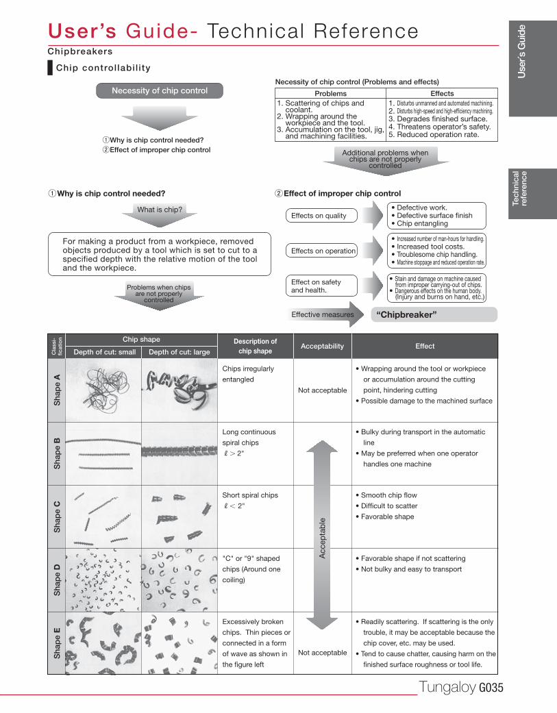
Chip shape
Depth of cut: small Depth of cut: large
Description ofchip shape
Acceptability Effect
Cla
ssi-
ficat
ion
Sha
pe
AS
hap
e B
Sha
pe
CS
hap
e D
Sha
pe
E
Chips irregularly
entangled
• Wrapping around the tool or workpiece
or accumulation around the cutting
point, hindering cutting
• Possible damage to the machined surface
Long continuous
spiral chips
R� 2"
Short spiral chips
R� 2"
"C" or "9" shaped
chips (Around one
coiling)
Excessively broken
chips. Thin pieces or
connected in a form
of wave as shown in
the figure left
• Bulky during transport in the automatic
line
• May be preferred when one operator
handles one machine
• Smooth chip flow
• Difficult to scatter
• Favorable shape
• Favorable shape if not scattering
• Not bulky and easy to transport
• Readily scattering. If scattering is the only
trouble, it may be acceptable because the
chip cover, etc. may be used.
• Tend to cause chatter, causing harm on the
finished surface roughness or tool life.
Accep
tab
le
Not acceptable
Not acceptable
Chip control labi l i ty
Necessity of chip control
Why is chip control needed?Effect of improper chip control
Why is chip control needed?
What is chip?
For making a product from a workpiece, removedobjects produced by a tool which is set to cut to aspecified depth with the relative motion of the tooland the workpiece.
Problems when chips are not properly
controlled
Necessity of chip control (Problems and effects)
Problems Effects1. Scattering of chips and coolant.2. Wrapping around the workpiece and the tool.3. Accumulation on the tool, jig, and machining facilities.
1. Disturbs unmanned and automated machining.2. Disturbs high-speed and high-efficiency machining.3. Degrades finished surface.4. Threatens operator’s safety. 5. Reduced operation rate.
Additional problems when chips are not properly
controlled
Effects on quality
Effects on operation
Effect on safetyand health.
• Defective work.• Defective surface finish• Chip entangling
• Increased number of man-hours for handling.• Increased tool costs.• Troublesome chip handling.• Machine stoppage and reduced operation rate.
• Stain and damage on machine caused from improper carrying-out of chips.• Dangerous effects on the human body. (Injury and burns on hand, etc.)
Effective measures “Chipbreaker”
Effect of improper chip control
Chipbreakers
Use
r´s G
uide
www.tungaloyamerica.comG036
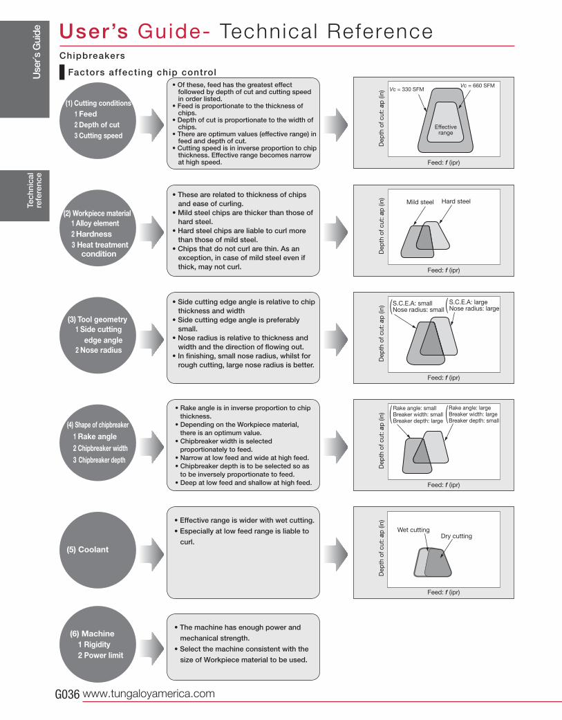
Vc = 660 SFMVc = 330 SFM
Tec
hnic
alre
fere
nce
User’s Guide- Technica l Reference
• Of these, feed has the greatest effect followed by depth of cut and cutting speed in order listed.
• Feed is proportionate to the thickness of chips.
• Depth of cut is proportionate to the width of chips.
• There are optimum values (effective range) in feed and depth of cut.
• Cutting speed is in inverse proportion to chip thickness. Effective range becomes narrow at high speed.
• These are related to thickness of chips and ease of curling.
• Mild steel chips are thicker than those of hard steel.
• Hard steel chips are liable to curl more than those of mild steel.
• Chips that do not curl are thin. As an exception, in case of mild steel even if thick, may not curl.
• Side cutting edge angle is relative to chip thickness and width
• Side cutting edge angle is preferably small.
• Nose radius is relative to thickness and width and the direction of flowing out.
• In finishing, small nose radius, whilst for rough cutting, large nose radius is better.
• Effective range is wider with wet cutting.
• Especially at low feed range is liable to
curl.
• Rake angle is in inverse proportion to chip thickness.
• Depending on the Workpiece material, there is an optimum value.
• Chipbreaker width is selected proportionately to feed.
• Narrow at low feed and wide at high feed.• Chipbreaker depth is to be selected so as
to be inversely proportionate to feed.• Deep at low feed and shallow at high feed.
• The machine has enough power and
mechanical strength.
• Select the machine consistent with the
size of Workpiece material to be used.
Factors affect ing chip control
(1) Cutting conditions 1 Feed 2 Depth of cut 3 Cutting speed
(2) Workpiece material 1 Alloy element 2 Hardness
3 Heat treatment condition
(3) Tool geometry 1 Side cutting
edge angle 2 Nose radius
(4) Shape of chipbreaker 1 Rake angle 2 Chipbreaker width 3 Chipbreaker depth
(5) Coolant
(6) Machine 1 Rigidity 2 Power limit
Effectiverange
Dep
th o
f cu
t: a
p (in
)
Feed: f (ipr)
Dep
th o
f cu
t: a
p (in
)
Feed: f (ipr)
Dep
th o
f cu
t: a
p (in
)Feed: f (ipr)
Dep
th o
f cu
t: a
p (in
)
Feed: f (ipr)
Dep
th o
f cu
t: a
p (in
)
Feed: f (ipr)
S.C.E.A: smallNose radius: small
S.C.E.A: largeNose radius: large
Rake angle: smallBreaker width: smallBreaker depth: large
Rake angle: largeBreaker width: largeBreaker depth: small
Wet cuttingDry cutting
Mild steel Hard steel
Chipbreakers
Use
r´s G
uide
Tungaloy G037
(+)
(-)
(+)
(+)
(-)
(-)
+
+
+
��
�
�
�
��
��
�
×
+
-
+
��
��
��
�
�
�
�
�
-
-
-
�
×
�
��
×
×
×
�
TGN4200DoPent
TAW13TME4400TMD4400
THF4000THE4000
A.R. A.R. A.R.
R.R. R.R. R.R.
Tec
hnic
alre
fere
nce
User’s Guide- Technica l Reference
γp (A.R.)
γf (R.R.)
γo
Carbon steels, alloy steels (� 300HB)
Stainless steels (� 300HB)
Die steels (� 300HB)
Cast irons Ductile cast irons
Aluminum alloys
Copper and its alloys
Titanium and its alloys
Hardened steels (40 ~ 55HRC)
· Higher cutting edge strength· Many usable corners of inserts
· Excellent chip removal· Higher cutting edge strength and Freer cutting action
· Most excellent cutting action
Shapes of
cutting edge
Workpiece material
Features
Typical examples of mills
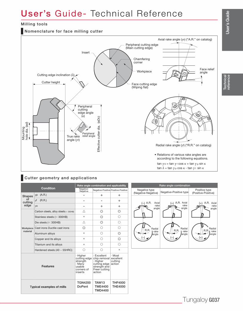
Nomenclature for face mil l ing cutter
Cutter geometry and appl icat ions
Rake angle combination and applicabilityCondition
• Relations of various rake angles are
according to the following equations.
Cutter height
Peripheral cutting edge angle (κ)
Peripheral relief angleTrue rake
angle (γ0)
Cutting edge inclination (λ)
Eff
ective c
utt
er
dia
. (ø
Dc)
Mo
un
tin
gh
ole
dia
. (ø
d)
Peripheral cutting edge (Main cutting edge)
Chamferingcorner
Workpiece
Face cutting edge(Wiping flat)
Insert
Axial rake angle (γp) (“A.R.” on catalog)
Face reliefangle
Radial rake angle (γf) (“R.R.” on catalog)
Axialrake
angle
Axialrake
angle
Axialrake
angle
Radialrake
angle
Radialrake
angle
Radialrake
angle
Negative type(Negative-Negative) Negative-Positive type
Positive type(Positive-Positive)
Rake angle combination
tan γ 0 = tan γ f cos κ + tan γ p sin κtan λ = tan γ p cos κ - tan γ f sin κ
Positive-PositiveNegative-PositiveNegative-Negative
Mil l ing tools
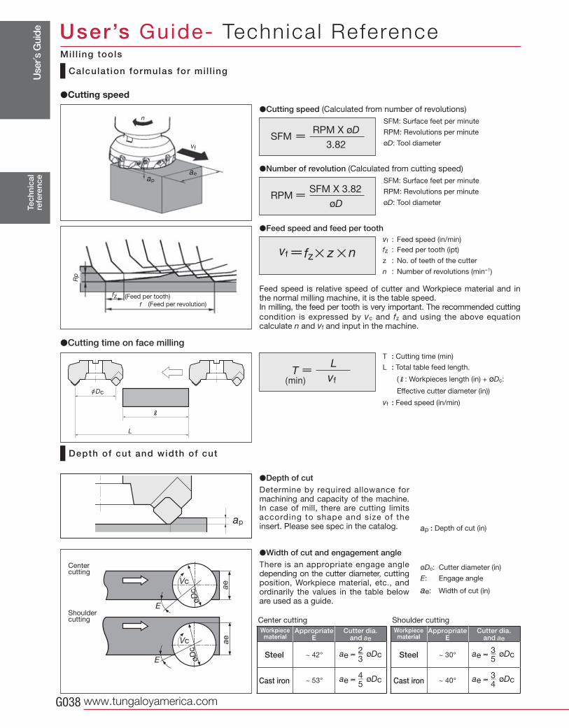
Use
r´s G
uide
www.tungaloyamerica.comG038
f
fz
Rp
f
n
aeap
vf
~ 53° ~ 40°
~ 42° ~ 30°
Tec
hnic
alre
fere
nce
User’s Guide- Technica l Reference
Appropriate Cutter dia. E and ae
Appropriate Cutter dia. E and ae
Steel
Cast iron Cast iron
�Cutting speed
�Cutting time on face milling
Calculat ion formulas for mi l l ing
Depth of cut and width of cut
(Feed per tooth)
(Feed per revolution)
�Cutting speed (Calculated from number of revolutions)
�Number of revolution (Calculated from cutting speed)
�Feed speed and feed per toothvf : Feed speed (in/min)
fz : Feed per tooth (ipt)
z : No. of teeth of the cutter
n : Number of revolutions (min-1)
Feed speed is relative speed of cutter and Workpiece material and in the normal milling machine, it is the table speed.In milling, the feed per tooth is very important. The recommended cutting
condition is expressed by vc and fz and using the above equation calculate n and vf and input in the machine.
T : Cutting time (min)
L : Total table feed length.
(R: Workpieces length (in) + øDc:
Effective cutter diameter (in))
vf : Feed speed (in/min)
2ae � øDc
3
3ae � øDc
5
4ae � øDc
5
3ae � øDc
4
�Depth of cutDetermine by required allowance for machining and capacity of the machine. In case of mill, there are cutting limits according to shape and size of the insert. Please see spec in the catalog.
�Width of cut and engagement angleThere is an appropriate engage angle depending on the cutter diameter, cutting position, Workpiece material, etc., and ordinarily the values in the table below are used as a guide.
øDc: Cutter diameter (in)
E: Engage angle
ae: Width of cut (in)
ap : Depth of cut (in)
Center cutting
Shoulder cutting Center cutting Shoulder cutting
Workpiecematerial
Workpiecematerial
Steel
Mil l ing tools
RPM X øDSFM
3.82
SFM: Surface feet per minute
RPM: Revolutions per minute
øD: Tool diameter
SFM X 3.82RPM
øD
SFM: Surface feet per minute
RPM: Revolutions per minute
øD: Tool diameter
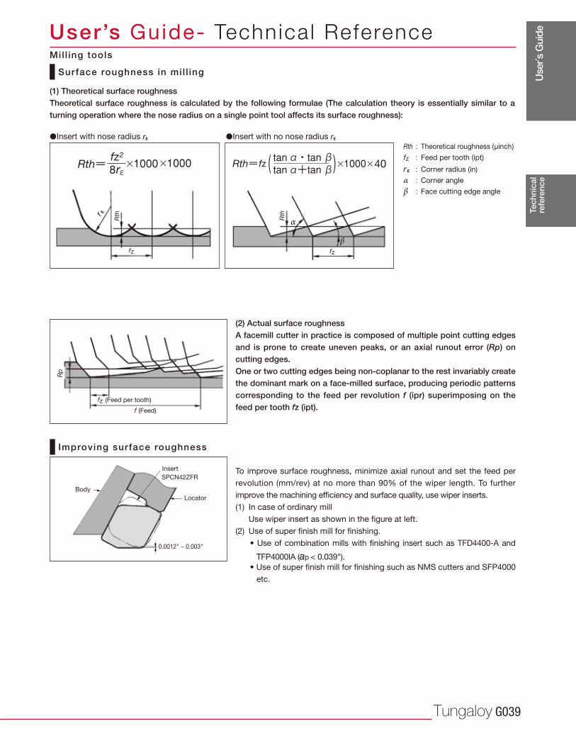
Use
r´s G
uide
Tungaloy G039
r 40
Rp
Rth
fz
r ε
Rth
α
βfz
fz
SPCN42ZFR
0.0012" ~ 0.003"
Tec
hnic
alre
fere
nce
User’s Guide- Technica l Reference
Surface roughness in mil l ing
Improving surface roughness
(1) Theoretical surface roughness Theoretical surface roughness is calculated by the following formulae (The calculation theory is essentially similar to a turning operation where the nose radius on a single point tool affects its surface roughness):
Rth : Theoretical roughness (μinch)
fz : Feed per tooth (ipt)
r ε : Corner radius (in)
α : Corner angle
β : Face cutting edge angle
�Insert with nose radius r ε �Insert with no nose radius r ε
(Feed per tooth)
(Feed)
(2) Actual surface roughness A facemill cutter in practice is composed of multiple point cutting edges and is prone to create uneven peaks, or an axial runout error (Rp) on cutting edges. One or two cutting edges being non-coplanar to the rest invariably create the dominant mark on a face-milled surface, producing periodic patterns corresponding to the feed per revolution f (ipr) superimposing on the feed per tooth fz (ipt).
To improve surface roughness, minimize axial runout and set the feed per
revolution (mm/rev) at no more than 90% of the wiper length. To further
improve the machining efficiency and surface quality, use wiper inserts.
(1) In case of ordinary mill
Use wiper insert as shown in the figure at left.
(2) Use of super finish mill for finishing.
• Use of combination mills with finishing insert such as TFD4400-A and
TFP4000IA (ap < 0.039").
• Use of super finish mill for finishing such as NMS cutters and SFP4000
etc.
Body
Insert
Locator
f
Mil l ing tools
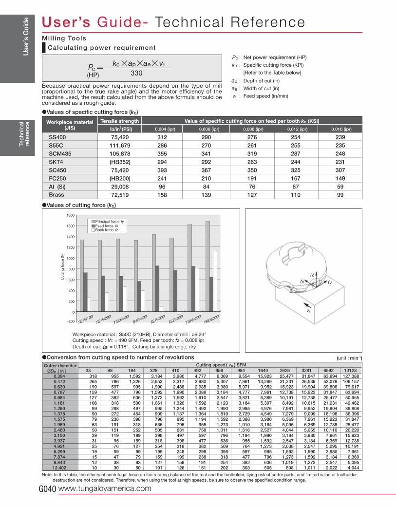
Use
r´s G
uide
www.tungaloyamerica.comG040
øDc 33 98 164 328 410 492 656 984 1640 2625 3281 6562 131230.394 318 955 1,592 3,184 3,980 4,777 6,369 9,554 15,923 25,477 31,847 63,694 127,388 0.472 265 796 1,326 2,653 3,317 3,980 5,307 7,961 13,269 21,231 26,539 53,078 106,157 0.630 199 597 995 1,990 2,488 2,985 3,980 5,971 9,952 15,923 19,904 39,808 79,617 0.787 159 477 796 1,592 1,990 2,388 3,184 4,777 7,961 12,738 15,923 31,847 63,694 0.984 127 382 636 1,273 1,592 1,910 2,547 3,821 6,369 10,191 12,738 25,477 50,955 1.181 106 318 530 1,061 1,326 1,592 2,123 3,184 5,307 8,492 10,615 21,231 42,462 1.260 99 298 497 995 1,244 1,492 1,990 2,985 4,976 7,961 9,952 19,904 39,808 1.378 90 272 454 909 1,137 1,364 1,819 2,729 4,549 7,279 9,099 18,198 36,396 1.575 79 238 398 796 995 1,194 1,592 2,388 3,980 6,369 7,961 15,923 31,847 1.969 63 191 318 636 796 955 1,273 1,910 3,184 5,095 6,369 12,738 25,477 2.480 50 151 252 505 631 758 1,011 1,516 2,527 4,044 5,055 10,110 20,220 3.150 39 119 199 398 497 597 796 1,194 1,990 3,184 3,980 7,961 15,923 3.937 31 95 159 318 398 477 636 955 1,592 2,547 3,184 6,369 12,738 4.921 25 76 127 254 318 382 509 764 1,273 2,038 2,547 5,095 10,191 6.299 19 59 99 199 248 298 398 597 995 1,592 1,990 3,980 7,961 7.874 15 47 79 159 199 238 318 477 796 1,273 1,592 3,184 6,369 9.843 12 38 63 127 159 191 254 382 636 1,019 1,273 2,547 5,095 12.402 10 30 50 101 126 151 202 303 505 808 1,011 2,022 4,044
330(HP)
fx fy
vf
fz
SS400 75,420 S55C 111,679 SCM435 105,878 SKT4 (HB352) SC450 75,420 FC250 (HB200) Al (Si) 29,008 72,519
( in )
THF4400
TGP4100
TGP4200
TSP4000
TGD4400
TSE4000
TGN4200
TRD6000
1800
1600
1400
1200
1000
800
600
400
200
-200
0
312 286 355 294 393 241 96
158
290 270 341 292 367 210 84
139
276 261 319 263 350 191 76
127
254 255 287 244 325 167 67
110
239 235 248 231 307 149 59 99
Tec
hnic
alre
fere
nce
User’s Guide- Technica l Reference
lb/in2 (PSI) 0.004 (ipr) 0.006 (ipr) 0.008 (ipr) 0.012 (ipr) 0.016 (ipr)
Tensile strength Value of specific cutting force on feed per tooth kc (KSI)Workpiece material(JIS)
�Conversion from cutting speed to number of revolutions (unit : min-1)
Pc : Net power requirement (HP)
kc : Specific cutting force (KPI)
[Refer to the Table below]
ap : Depth of cut (in)
ae : Width of cut (in)
vf : Feed speed (in/min)
Because practical power requirements depend on the type of mill (proportional to the true rake angle) and the motor efficiency of the machine used, the result calculated from the above formula should be considered as a rough guide.
�Values of cutting force (kc)
Note: In this table, the effects of centrifugal force on the rotating balance of the tool and the toolholder, flying risk of cutter parts, and limited value of toolholder
destruction are not considered. Therefore, when using the tool at high speeds, be sure to observe the specified condition range.
Calculat ing power requirement
Principal force
Feed forceBack force
fyfxfz
Cutt
ing
fo
rce (N
)
Workpiece material : S50C (210HB), Diameter of mill : ø6.29"
Cutting speed : Vc = 490 SFM, Feed per tooth: fz = 0.008 ipt
Depth of cut: ap = 0.118", Cutting by a single edge, dry
Cutter diameter Cutting speed ( vc ) SFM
Brass
Mil l ing Tools
�Values of specific cutting force (kc)
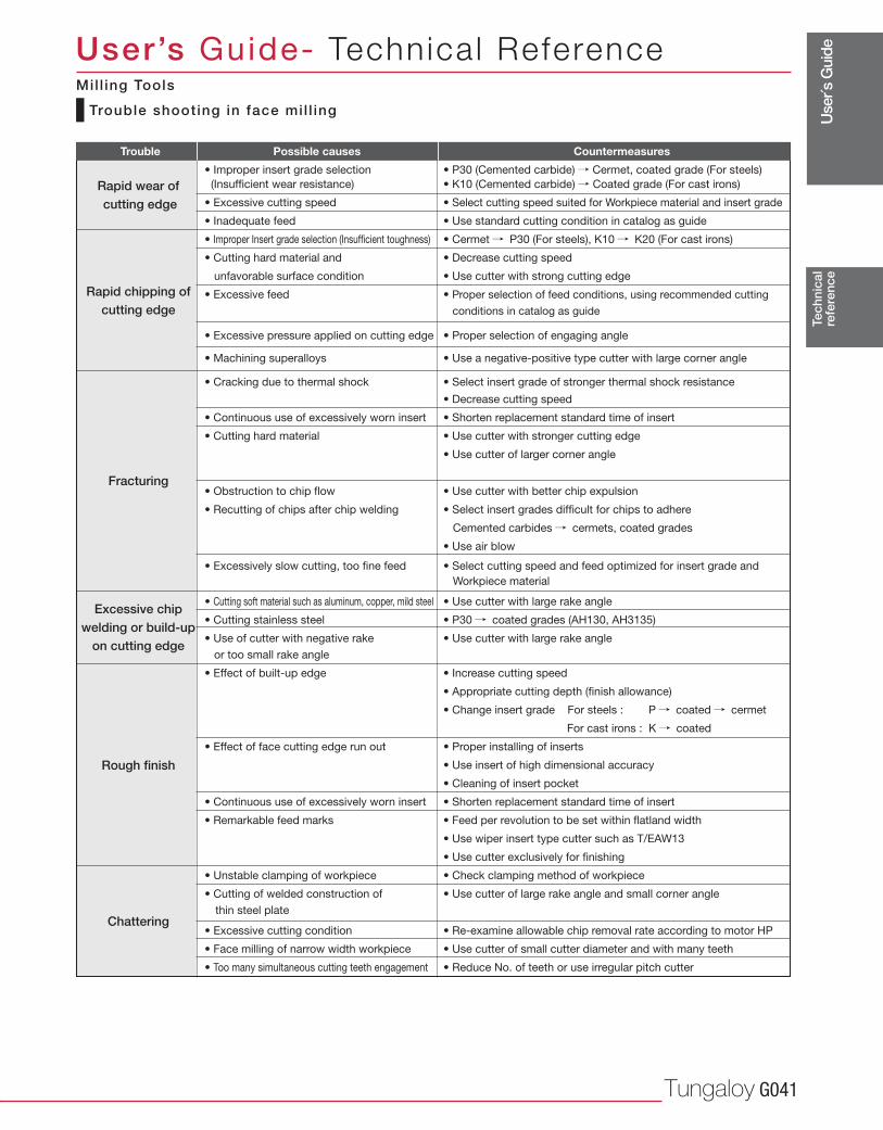
Use
r´s G
uide
Tungaloy G041
Tec
hnic
alre
fere
nce
User’s Guide- Technica l Reference
Trouble shooting in face mil l ing
Mil l ing Tools
Rapid wear of cutting edge
Rapid chipping of cutting edge
Fracturing
Excessive chip welding or build-up
on cutting edge
Rough finish
• Improper insert grade selection • P30 (Cemented carbide) / Cermet, coated grade (For steels)
(Insufficient wear resistance) • K10 (Cemented carbide) / Coated grade (For cast irons)
• Excessive cutting speed • Select cutting speed suited for Workpiece material and insert grade
• Inadequate feed • Use standard cutting condition in catalog as guide
• Improper Insert grade selection (Insufficient toughness) • Cermet / P30 (For steels), K10 / K20 (For cast irons)
• Cutting hard material and • Decrease cutting speed
unfavorable surface condition • Use cutter with strong cutting edge
• Excessive feed • Proper selection of feed conditions, using recommended cutting
conditions in catalog as guide
• Excessive pressure applied on cutting edge • Proper selection of engaging angle
• Machining superalloys • Use a negative-positive type cutter with large corner angle
• Cracking due to thermal shock • Select insert grade of stronger thermal shock resistance
• Decrease cutting speed
• Continuous use of excessively worn insert • Shorten replacement standard time of insert
• Cutting hard material • Use cutter with stronger cutting edge
• Use cutter of larger corner angle
• Obstruction to chip flow • Use cutter with better chip expulsion
• Recutting of chips after chip welding • Select insert grades difficult for chips to adhere
Cemented carbides / cermets, coated grades
• Use air blow
• Excessively slow cutting, too fine feed • Select cutting speed and feed optimized for insert grade and
Workpiece material
• Cutting soft material such as aluminum, copper, mild steel • Use cutter with large rake angle
• Cutting stainless steel • P30 / coated grades (AH130, AH3135)
• Use of cutter with negative rake • Use cutter with large rake angle
or too small rake angle
• Effect of built-up edge • Increase cutting speed
• Appropriate cutting depth (finish allowance)
• Change insert grade For steels : P / coated / cermet
For cast irons : K / coated
• Effect of face cutting edge run out • Proper installing of inserts
• Use insert of high dimensional accuracy
• Cleaning of insert pocket
• Continuous use of excessively worn insert • Shorten replacement standard time of insert
• Remarkable feed marks • Feed per revolution to be set within flatland width
• Use wiper insert type cutter such as T/EAW13
• Use cutter exclusively for finishing
• Unstable clamping of workpiece • Check clamping method of workpiece
• Cutting of welded construction of • Use cutter of large rake angle and small corner angle
thin steel plate
• Excessive cutting condition • Re-examine allowable chip removal rate according to motor HP
• Face milling of narrow width workpiece • Use cutter of small cutter diameter and with many teeth
• Too many simultaneous cutting teeth engagement • Reduce No. of teeth or use irregular pitch cutter
Chattering
Trouble Possible causes Countermeasures
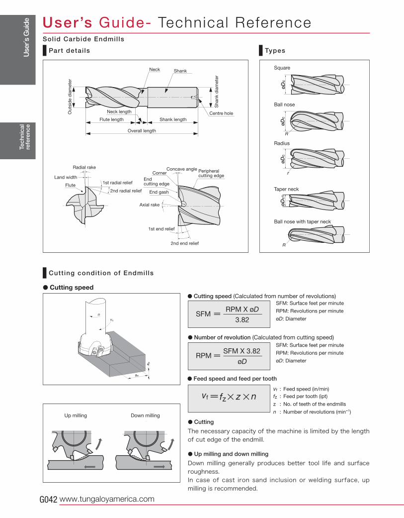
Use
r´s G
uide
www.tungaloyamerica.comG042
øD
cø
Dc
øD
cø
Dc1
Tec
hnic
alre
fere
nce
User’s Guide- Technica l Reference
Square
Ball nose
Radius
Taper neck
Ball nose with taper neck
Part detai ls Types
Ou
tsid
e d
iam
ete
r
Sh
an
k d
iam
ete
r
Neck length
Shank length
Neck Shank
Flute length
Radial rake
Centre hole
Overall length
1st radial relief
Concave angle
Flute
2nd radial relief
Axial rake
Endcutting edge
Corner Peripheralcutting edge
End gash
Land width
2nd end relief
1st end relief
Cutt ing condit ion of Endmil ls
� Cutting
The necessary capacity of the machine is limited by the length of cut edge of the endmill.
� Up milling and down milling
Down milling generally produces better tool life and surface roughness.In case of cast iron sand inclusion or welding surface, up milling is recommended.
Up milling Down milling
� Cutting speed� Cutting speed (Calculated from number of revolutions)
� Number of revolution (Calculated from cutting speed)
� Feed speed and feed per tooth
vf : Feed speed (in/min)
fz : Feed per tooth (ipt)
z : No. of teeth of the endmills
n : Number of revolutions (min-1)
Solid Carbide Endmil ls
RPM X øDSFM
3.82
SFM: Surface feet per minute
RPM: Revolutions per minute
øD: Diameter
SFM X 3.82RPM
øD
SFM: Surface feet per minute
RPM: Revolutions per minute
øD: Diameter
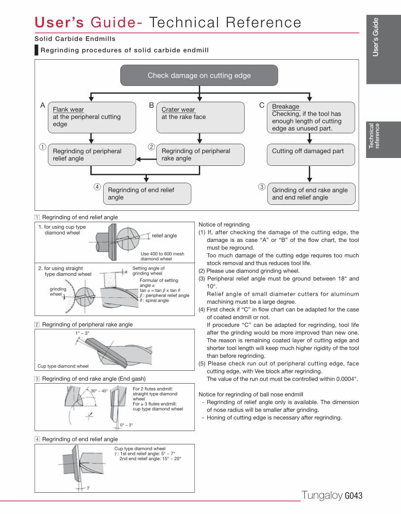
Use
r´s G
uide
Tungaloy G043γ
α
1° ~ 3°
30° ~ 45°
0° ~ 3°
¡
™
£
¢
Tec
hnic
alre
fere
nce
User’s Guide- Technica l Reference
A B C
Regrinding of end relief angle
Notice of regrinding
(1) If, after checking the damage of the cutting edge, the
damage is as case “A” or “B” of the flow chart, the tool
must be reground.
Too much damage of the cutting edge requires too much
stock removal and thus reduces tool life.
(2) Please use diamond grinding wheel.
(3) Peripheral relief angle must be ground between 18° and
10°.
Relief angle of small diameter cutters for aluminum
machining must be a large degree.
(4) First check if “C” in flow chart can be adapted for the case
of coated endmill or not.
If procedure “C” can be adapted for regrinding, tool life
after the grinding would be more improved than new one.
The reason is remaining coated layer of cutting edge and
shorter tool length will keep much higher rigidity of the tool
than before regrinding.
(5) Please check run out of peripheral cutting edge, face
cutting edge, with Vee block after regrinding.
The value of the run out must be controlled within 0.0004".
Notice for regrinding of ball nose endmill
- Regrinding of relief angle only is available. The dimension
of nose radius will be smaller after grinding.
- Honing of cutting edge is necessary after regrinding.
1. for using cup type diamond wheel
Regrinding procedures of sol id carbide endmil l
relief angle
Use 400 to 600 mesh diamond wheel
2. for using straight type diamond wheel
grindingwheel
Setting angle of grinding wheel
Formular of settingangle α tan α = tan β x tan θ β : peripheral relief angle θ : spiral angle
Regrinding of peripheral rake angle
Cup type diamond wheel
Regrinding of end rake angle (End gash)
For 2 flutes endmill:straight type diamondwheelFor 3 flutes endmill:cup type diamond wheel
Regrinding of end relief angle
Cup type diamond wheelγ : 1st end relief angle: 5° ~ 7° 2nd end relief angle: 15° ~ 20°
Flank wear at the peripheral cuttingedge
Regrinding of peripheralrelief angle
Crater wear at the rake face
Regrinding of peripheralrake angle
Breakage Checking, if the tool hasenough length of cuttingedge as unused part.
Cutting off damaged part
Regrinding of end reliefangle
Grinding of end rake angleand end relief angle
Check damage on cutting edge
Solid Carbide Endmil ls
Use
r´s G
uide
www.tungaloyamerica.comG044
Tec
hnic
alre
fere
nce
User’s Guide- Technica l ReferenceMEMO
Use
r´s G
uide
Tungaloy G045
Tec
hnic
alre
fere
nce
User’s Guide- Technica l ReferenceMEMO
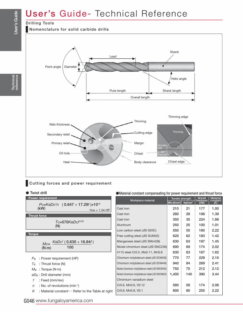
Use
r´s G
uide
www.tungaloyamerica.comG046
Pc=KøDc2n ( 0.647 + 17.29f )×10-6
(kW)
(N)
Mc= (N·m)
KøDc2 ( 0.630 + 16.84f )100
Tc=570KøDcf 0.85
210 21 177 1.00
280 28 198 1.39
350 35 224 1.88
250 25 100 1.01
550 55 160 2.22
620 62 183 1.42
630 63 197 1.45
690 69 174 2.02
630 63 167 1.62
770 77 229 2.10
940 94 269 2.41
750 75 212 2.12
1,400 140 390 3.44
580 58 174 2.08
800 80 255 2.22
1kw = 1.34 HP
Tec
hnic
alre
fere
nce
User’s Guide- Technica l Reference
Material constant
(K)
Brinell hardness
(HB)Kgf/mm2
Tensile strengthWorkpiece material
Cast iron
Cast iron
Cast iron
Aluminum
Low carbon steel (JIS S20C)
Free cutting steel (JIS SUM32)
Manganese steel (JIS SMn438)
Nickel chromium steel (JIS SNC236)
4115 steel Cr0.5, Mo0.11, Mn0.8
Chromium molybdenum steel (JIS SCM430)
Chromium molybdenum steel (JIS SCM440)
Nickel chromium molybdenum steel (JIS SNCM420)
Nickel chromium molybdenum steel (JIS SNCM625)
Chromium vanadium steel
Cr0.6, Mn0.6, V0.12
Cr0.8, Mn0.8, V0.1
Torque
Thrust force
Power requirement
Nomenclature for sol id carbide dri l ls
Cutt ing forces and power requirement
� Twist drill
Pc : Power requirement (HP)
Tc : Thrust force (N)
Mc : Torque (N·m)
øDc : Drill diameter (mm)
f : Feed (mm/rev)
n : No. of revolutions (min-1)
K : Material constant.... Refer to the Table at right
�Material constant compensating for power requirement and thrust force
Point angle Diameter
Lead
Shank
Helix angle
Flute length Shank length
Overall length
Web thickness
Secondary relief
Primary relief
Oil hole
Heel
Thinning
Cutting edge
Margin
Chisel
Body clearance
Thinning edge
Chisel edge
Primary relief
Secondary relief
Thinning
MPa (N/mm2)
Dri l l ing Tools
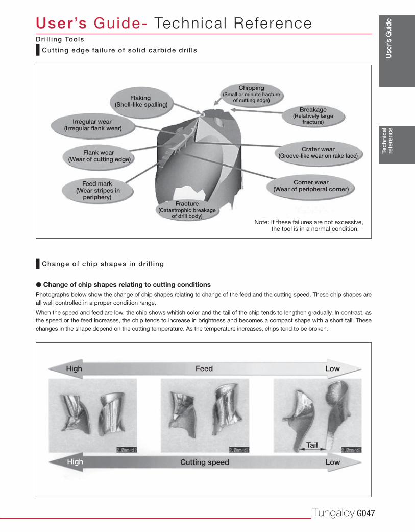
Use
r´s G
uide
Tungaloy G047
Tec
hnic
alre
fere
nce
User’s Guide- Technica l Reference
Cutt ing edge fai lure of sol id carbide dri l ls
Change of chip shapes in dr i l l ing
� Change of chip shapes relating to cutting conditionsPhotographs below show the change of chip shapes relating to change of the feed and the cutting speed. These chip shapes are
all well controlled in a proper condition range.
When the speed and feed are low, the chip shows whitish color and the tail of the chip tends to lengthen gradually. In contrast, as
the speed or the feed increases, the chip tends to increase in brightness and becomes a compact shape with a short tail. These
changes in the shape depend on the cutting temperature. As the temperature increases, chips tend to be broken.
Flaking (Shell-like spalling)
Irregular wear (Irregular flank wear)
Flank wear (Wear of cutting edge)
Feed mark (Wear stripes in
periphery)
Chipping (Small or minute fracture
of cutting edge)
Breakage(Relatively large
fracture)
Crater wear (Groove-like wear on rake face)
Corner wear (Wear of peripheral corner)
Fracture (Catastrophic breakage
of drill body)Note: If these failures are not excessive,
the tool is in a normal condition.
High
High
Feed
Cutting speed
Low
Tail
Low
Dri l l ing Tools
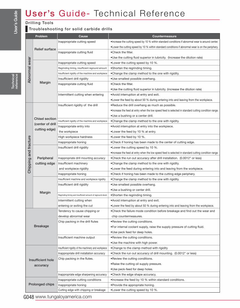
Use
r´s G
uide
www.tungaloyamerica.comG048
Tec
hnic
alre
fere
nce
User’s Guide- Technica l Reference
Inappropriate cutting speed •Increase the cutting speed by 10 % within standard conditions if abnormal wear is around center.
•Lower the cutting speed by 10 % within standard conditions if abnormal wear is on the periphery.
Inappropriate cutting fluid •Check the filter.
•Use the cutting fluid superior in lubricity. (Increase the dilution rate)
Inappropriate cutting speed •Lower the cutting speed by 10 %.
Regrinding timing, insufficient reground amount •Shorten the regrinding timing.
Insufficient rigidity of the machine and workpiece •Change the clamp method to the one with rigidity.
Insufficient drill rigidity •Use smallest possible overhang.
Inappropriate cutting fluid •Check the filter.
•Use the cutting fluid superior in lubricity. (increase the dilution rate)
Intermittent cutting when entering •Avoid interruption at entry and exit.
•Lower the feed by about 50 % during entering into and leaving from the workpiece.
Insufficient rigidity of the drill •Reduce the drill overhang as much as possible.
•Increase the feed at entry when the low speed feed is selected in standard cutting condition range.
•Use a bushing or a center drill.
Insufficient rigidity of the machine and workpiece •Change the clamp method to the one with rigidity.
Inappropriate entry into •Avoid interruption at entry into the workpiece.
the workpiece •Lower the feed by 10 % at entry.
High workpiece hardness •Lower the feed by 10 %.
Inappropriate honing •Check if honing has been made to the center of cutting edge.
Insufficient drill rigidity •Lower the cutting speed by 10 %.
•Increase the feed at entry when the low speed feed is selected in standard cutting condition range.
Inappropriate drill mounting accuracy •Check the run out accuracy after drill installation. (0.0012" or less)
Insufficient machinery •Change the clamp method to the one with rigidity.
and workpiece rigidity •Lower the feed during entering into and leaving from the workpiece.
Inappropriate honing •Check if honing has been made to the cutting edge periphery.
Insufficient machine and workpiece rigidity •Change the clamp method to the one with rigidity.
Insufficient drill rigidity •Use smallest possible overhang.
•Use a bushing or center drill.
Regrinding timing and insufficient amount of reground stock •Shorten the regrinding timing.
Intermittent cutting when •Avoid interruption at entry and exit.
entering or exiting the cut •Lower the feed by about 50 % during entering into and leaving from the workpiece.
Tendency to cause chipping or •Check the failure mode condition before breakage and find out the wear and
develop abnormal wear chip countermeasures.
Chip packing in the drill flutes •Review the cutting conditions.
•For internal coolant supply, raise the supply pressure of cutting fluid.
•Use peck feed for deep holes.
Insufficient machine output •Review the cutting conditions.
•Use the machine with high power.
Insufficient rigidity of the machinery and workpiece •Change to the clamp method with rigidity
Inappropriate drill installation accuracy •Check the run out accuracy of drill mounting. (0.0012" or less)
Chip packing in the flutes. •Review the cutting conditions.
•Raise the cutting oil supply pressure.
•Use peck-feed for deep holes.
Inappropriate edge sharpening accuracy •Check the edge shape accuracy.
Inappropriate cutting conditions •Increase the feed by 10 % within standard conditions.
Inappropriate honing •Provide the appropriate honing.
Cutting edge with chipping or breakage •Lower the cutting speed by 10 %.
Relief surface
Margin
Chisel section
(center of drill
cutting edge)
Peripheral
cutting edge
Margin
Ab
norm
al w
ear
Chi
pp
ing
and
fra
ctur
e
Breakage
Insufficient hole
accuracy
Prolonged chips
Problem Cause Countermeasure
Troubleshooting for sol id carbide dri l ls
Dri l l ing Tools
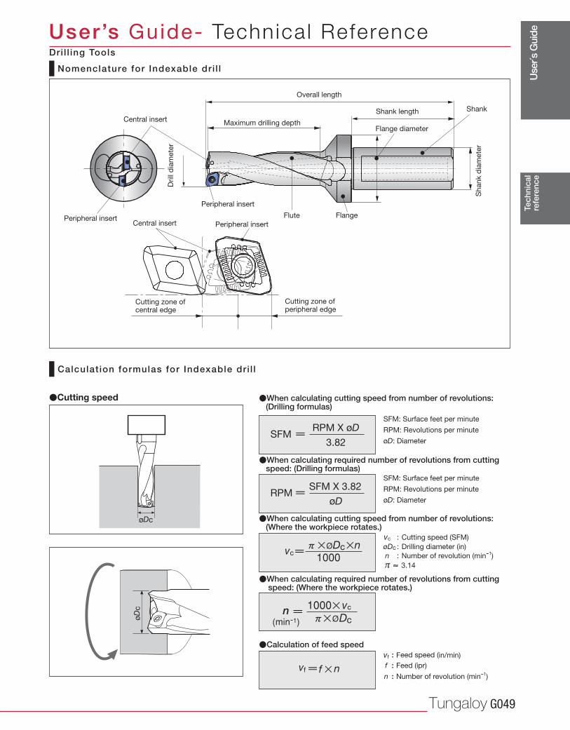
Use
r´s G
uide
Tungaloy G049
øD
c
øDc T
echn
ical
refe
renc
e
User’s Guide- Technica l Reference
Nomenclature for Indexable dr i l l
Calculat ion formulas for Indexable dr i l l
�When calculating cutting speed from number of revolutions: (Drilling formulas)
�When calculating required number of revolutions from cutting speed: (Drilling formulas)
vf : Feed speed (in/min)
f : Feed (ipr)
n : Number of revolution (min-1)
�Calculation of feed speed
�Cutting speed
�When calculating cutting speed from number of revolutions: (Where the workpiece rotates.)
�When calculating required number of revolutions from cutting speed: (Where the workpiece rotates.)
vc : Cutting speed (SFM)
øDc : Drilling diameter (in)
n : Number of revolution (min-1)
π 3.14
Central insert
Central insert
Drill
dia
mete
r
Sh
an
k d
iam
ete
r
Cutting zone ofperipheral edge
FlangeFlute
Shank length
Maximum drilling depth
Overall length
Shank
Flange diameter
Cutting zone of central edge
Peripheral insert
Dri l l ing Tools
Peripheral insert
Peripheral insert
RPM X øDSFM
3.82
SFM: Surface feet per minute
RPM: Revolutions per minute
øD: Diameter
SFM X 3.82RPM
øD
SFM: Surface feet per minute
RPM: Revolutions per minute
øD: Diameter
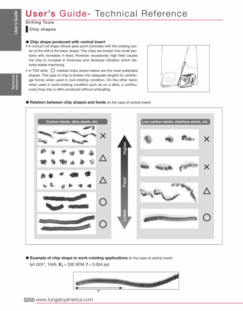
Use
r´s G
uide
www.tungaloyamerica.comG050
(ø1.024", 1045, Vc = 330 SFM, f = 0.004 ipr)
4"
Tec
hnic
alre
fere
nce
User’s Guide- Technica l Reference
Chip shapes
� Chip shape produced with central insert• A conical coil shape whose apex point coincides with the rotating cen-
ter of the drill is the basic shape. The chips are broken into small sec-
tions with increases in feed. However, excessively high feed causes
the chip to increase in thickness and develops vibration which dis-
turbs stable machining.
• In TDX drills, marked chips shown below are the most preferable
shapes. This type of chip is broken into adequate lengths by centrifu-
gal forces when used in tool-rotating condition. On the other hand,
when used in work-rotating condition such as on a lathe, a continu-
ously long chip is often produced without entangling.
� Relation between chip shapes and feeds (In the case of central insert)
� Example of chip shape in work-rotating applications (In the case of central insert)
Dri l l ing Tools
Low carbon steels, stainless steels, etc.Carbon steels, alloy steels, etc.H
ighe
rF
eed
Low
er

Use
r´s G
uide
Tungaloy G051
( ø0.866", Vc = 330 SFM, f = 0.004 ipr ) ( ø0.866", Vc = 530 SFM, f = 0.003 ipr )
f = 0.003 ipr f = 0.005 iprf = 0.004 ipr
Tec
hnic
alre
fere
nce
User’s Guide- Technica l Reference
Stainless steel (JIS SUS 304) Mild steel (JIS SS400)
DS
chip
bre
aker
DJ
chip
bre
aker
Stainless steels, low-carbon steels, low-alloy steels, etc.
Medium to high carbon steels, alloy steels, etc.
� Chip shape produced with peripheral insert• Chip problems such as entangling are mainly caused by chips pro-
duced with the peripheral insert. These problems are dependent
on the types of Workpiece material and the cutting conditions.
• As shown below, when the feed is extremely low, the chips jump
over the chipbreaker groove and the continuously long chips may
wrap around the drill body.
• When the feed is too high, the chips increase in thickness and can
not be curled.
• Therefore, it is important to select proper cutting conditions to suit
the machining so that well controlled chips will be formed.
� Typical chip shapes of general steels
As shown below, several turns of coil are an ideal shape.
As the feed increases, the curl radius and the number of turns tend to decrease.
� Variation of chip shapes relating to feeds
• When machining long-chip materials such as stainless steels and mild steels, the wrong selection of cutting conditions re-
sults in chip entangling and tool breakage at worst. Therefore, cutting conditions should be carefully selected.
• “C” shaped, continuous coils of several to ten turns having adequately divided lengths are the ideal shape.
� Ideal chip shapes
For machining stainless steels or low carbon steels,
DS chipbreaker is recommended.
When using a TDX drill in tool-rotating condition, DS
chipbreaker produces compact chips and allows more
stable machining than DJ chipbreaker. When using
it in work-rotating condition, DS chipbreaker pro-
vides outstanding affect on chip control.
Dri l l ing Tools
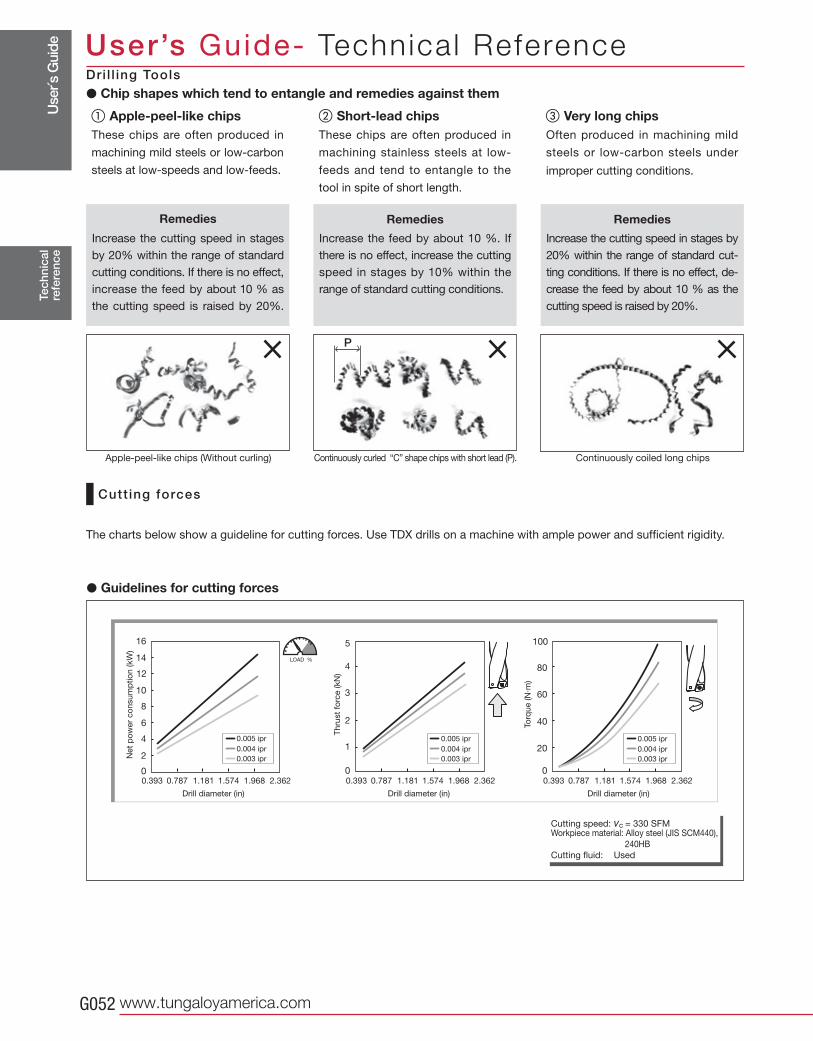
Use
r´s G
uide
www.tungaloyamerica.comG052
P
16
10
0
2
12
4
6
8
5
2
0
4
3
1
100
40
0
80
60
20
14
Tec
hnic
alre
fere
nce
User’s Guide- Technica l Reference
Cutt ing forces
� Chip shapes which tend to entangle and remedies against them
Apple-peel-like chipsThese chips are often produced in
machining mild steels or low-carbon
steels at low-speeds and low-feeds.
Remedies
Increase the cutting speed in stages
by 20% within the range of standard
cutting conditions. If there is no effect,
increase the feed by about 10 % as
the cutting speed is raised by 20%.
Short-lead chips These chips are often produced in
machining stainless steels at low-
feeds and tend to entangle to the
tool in spite of short length.
Remedies
Increase the feed by about 10 %. If
there is no effect, increase the cutting
speed in stages by 10% within the
range of standard cutting conditions.
Very long chipsOften produced in machining mild
steels or low-carbon steels under
improper cutting conditions.
Remedies
Increase the cutting speed in stages by
20% within the range of standard cut-
ting conditions. If there is no effect, de-
crease the feed by about 10 % as the
cutting speed is raised by 20%.
Apple-peel-like chips (Without curling) Continuously curled “C” shape chips with short lead (P). Continuously coiled long chips
Cutting speed: vc = 330 SFMWorkpiece material: Alloy steel (JIS SCM440),
240HB
Cutting fluid: Used
� Guidelines for cutting forces
The charts below show a guideline for cutting forces. Use TDX drills on a machine with ample power and sufficient rigidity.
Net
po
wer
co
nsu
mp
tio
n (kW
)
Th
rust
forc
e (kN
)
Torq
ue (N
·m)
Drill diameter (in) Drill diameter (in)Drill diameter (in)
LOAD %
� ��
Dri l l ing Tools
0.005 ipr
0.004 ipr
0.003 ipr
0.005 ipr
0.004 ipr
0.003 ipr
0.005 ipr
0.004 ipr
0.003 ipr
0.393 0.787 1.181 1.574 1.968 2.362 0.393 0.787 1.181 1.574 1.968 2.362 0.393 0.787 1.181 1.574 1.968 2.362
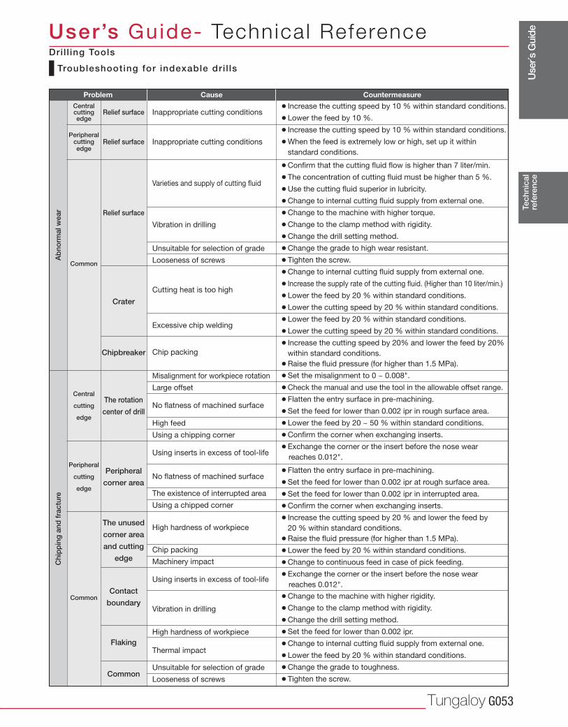
Use
r´s G
uide
Tungaloy G053
Tec
hnic
alre
fere
nce
User’s Guide- Technica l Reference
¡Increase the cutting speed by 10 % within standard conditions.
¡Lower the feed by 10 %.
¡Increase the cutting speed by 10 % within standard conditions.
¡ When the feed is extremely low or high, set up it within
standard conditions.
¡Confirm that the cutting fluid flow is higher than 7 liter/min.
¡The concentration of cutting fluid must be higher than 5 %.
¡Use the cutting fluid superior in lubricity.
¡Change to internal cutting fluid supply from external one.
¡Change to the machine with higher torque.
¡Change to the clamp method with rigidity.
¡Change the drill setting method.
¡Change the grade to high wear resistant.
¡Tighten the screw.
¡Change to internal cutting fluid supply from external one.
¡Increase the supply rate of the cutting fluid. (Higher than 10 liter/min.)
¡Lower the feed by 20 % within standard conditions.
¡Lower the cutting speed by 20 % within standard conditions.
¡Lower the feed by 20 % within standard conditions.
¡Lower the cutting speed by 20 % within standard conditions.
¡ Increase the cutting speed by 20% and lower the feed by 20%
within standard conditions.
¡Raise the fluid pressure (for higher than 1.5 MPa).
¡Set the misalignment to 0 ~ 0.008".
¡Check the manual and use the tool in the allowable offset range.
¡Flatten the entry surface in pre-machining.
¡Set the feed for lower than 0.002 ipr in rough surface area.
¡Lower the feed by 20 ~ 50 % within standard conditions.
¡Confirm the corner when exchanging inserts.
¡Exchange the corner or the insert before the nose wear
reaches 0.012".
¡Flatten the entry surface in pre-machining.
¡Set the feed for lower than 0.002 ipr at rough surface area.
¡Set the feed for lower than 0.002 ipr in interrupted area.
¡Confirm the corner when exchanging inserts.
¡ Increase the cutting speed by 20 % and lower the feed by
20 % within standard conditions.
¡Raise the fluid pressure (for higher than 1.5 MPa).
¡Lower the feed by 20 % within standard conditions.
¡Change to continuous feed in case of pick feeding.
¡Exchange the corner or the insert before the nose wear
reaches 0.012".
¡Change to the machine with higher rigidity.
¡Change to the clamp method with rigidity.
¡Change the drill setting method.
¡Set the feed for lower than 0.002 ipr.
¡Change to internal cutting fluid supply from external one.
¡Lower the feed by 20 % within standard conditions.
¡Change the grade to toughness.
¡Tighten the screw.
Inappropriate cutting conditions
Inappropriate cutting conditions
Varieties and supply of cutting fluid
Vibration in drilling
Unsuitable for selection of grade
Looseness of screws
Cutting heat is too high
Excessive chip welding
Chip packing
Misalignment for workpiece rotation
Large offset
No flatness of machined surface
High feed
Using a chipping corner
Using inserts in excess of tool-life
No flatness of machined surface
The existence of interrupted area
Using a chipped corner
High hardness of workpiece
Chip packing
Machinery impact
Using inserts in excess of tool-life
Vibration in drilling
High hardness of workpiece
Thermal impact
Unsuitable for selection of grade
Looseness of screws
Relief surface
Relief surface
Relief surface
Crater
Chipbreaker
The rotation
center of drill
Peripheral
corner area
The unused
corner area
and cutting
edge
Contact
boundary
Flaking
Common
Central cuttingedge
Peripheral cutting edge
Common
Central
cutting
edge
Peripheral
cutting
edge
Common
Ab
norm
al w
ear
Chi
pp
ing
and
fra
ctur
e
Problem Cause Countermeasure
Troubleshooting for indexable dr i l ls
Dri l l ing Tools
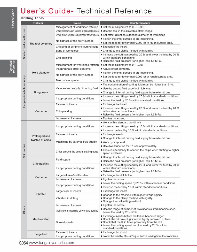
Use
r´s G
uide
www.tungaloyamerica.comG054
Tec
hnic
alre
fere
nce
User’s Guide- Technica l ReferenceProblem Cause Countermeasure
¡Set the misalignment to 0 ~ 0.008".
¡Use the tool in the allowable offset range.
¡Set offset direction extended diameter of workpiece
¡Flatten the entry surface in pre-machining.
¡Set the feed for lower than 0.002 ipr in rough surface area.
¡Exchange the insert.
¡Change to the clamp method with rigidity.
¡ Increase the cutting speed by 20 % and lower the feed by 20 %
within standard conditions.
¡Raise the fluid pressure (for higher than 1.5 MPa).
¡Set the misalignment to 0 ~ 0.008".
¡Adjust offset contents.
¡Flatten the entry surface in pre-machining.
¡Set the feed for lower than 0.002 ipr at rough surface area.
¡Change to the clamp method with rigidity.
¡The concentration of cutting fluid must be higher than 5 %.
¡Use the cutting fluid superior in lubricity.
¡Change to internal cutting fluid supply from external one.
¡Increase the cutting speed by 20 % within standard conditions.
¡Lower the feed by 20 % within standard conditions.
¡Exchange the insert.
¡ Increase the cutting speed by 20 % and lower the feed by 20 %
within standard conditions.
¡Raise the fluid pressure (for higher than 1.5 MPa).
¡Tighten the screw.
¡Work within standard conditions.
¡Increase the cutting speed by 10 % within standard conditions.
¡Increase the feed by 10 % within standard conditions.
¡Exchange inserts.
¡Change to internal cutting fluid supply from external one.
¡Work by step feed.
¡Use dwell function for 0.1 sec approximately.
¡ There is a tendency to shorten the chips when shifting to higher
speed and feed.
¡Change to internal cutting fluid supply from external one.
¡Raise the fluid pressure (for higher than 1.5 MPa).
¡ Increase the cutting speed by 20 % and lower the feed by 20 %
within standard conditions.
¡Raise the fluid pressure (for higher than 1.5 MPa).
¡Exchange the drill holder.
¡Tighten the screw.
¡Lower the cutting speed by 20 % within standard conditions.
¡Increase the feed by 10 % within standard conditions.
¡Exchange the insert.
¡Change to the machine with higher torque rigidity.
¡Change to the clamp method with rigidity.
¡Change the drill setting method.
¡Tighten the screw.
¡ Use the range of number of revolutions suited machine spec.
Lower the feed by 20 ~ 50%.
¡Exchange inserts before the failure becomes larger.¡Check the oil-hole plug screw is tightly screwed in place.¡Check that the fluid flows powerfully from the drill.¡Lower the cutting speed and the feed by 20 % within standard conditions.
¡Exchange the insert.
¡Lower the feed by 20 ~ 50% just before leaving from the workpiece.
Misalignment of workpiece rotation
Offset machining in excess of allowable range
Offset direction reduced diameter of workpiece
No flatness of the entry surface
Chipping of peripheral cutting edge
Bend of workpiece
Chip packing
Misalignment for workpiece rotation
Inappropriate offset contents
No flatness of the entry surface
Bend of workpiece
Varieties and supply of cutting fluid
Inappropriate cutting conditions
Failures of inserts
Chip packing
Looseness of screws
Inappropriate cutting conditions
Failures of inserts
Machining by external fluid supply
Chips around the central cutting edge
Fluid supply
Inappropriate cutting conditions
Large failure of drill holders
Looseness of screws
Inappropriate cutting conditions
Large wear of inserts
Vibration in drilling
Looseness of screws
Insufficient machine power and torque
Burned inserts
Failures of inserts
Inappropriate cutting conditions
The tool periphery
Hole diameter
Roughness
Common
Prolonged and
twisted of chips
Chip packing
Common
Chatter
Machine stop
Large burr
Scr
atch
mar
ks o
n th
e to
ol
Inap
pro
pri
ate
hole
acc
urac
yC
hip
co
ntro
lO
ther
s
Dri l l ing Tools
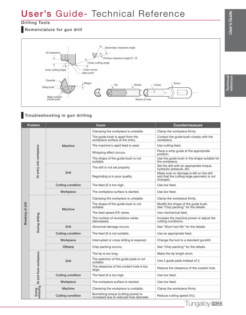
Use
r´s G
uide
Tungaloy G055
Tec
hnic
alre
fere
nce
User’s Guide- Technica l Reference
Problem Cause Countermeasure
Machine
Clamping the workpiece is unstable. Clamp the workpiece firmly.
The guide bush is apart from the workpiece surface at the entry.
Contact the guide bush closely with the workpiece.
The machine's rapid feed is used. Use cutting feed.
Whipping effect occurs. Place a whip guide at the appropriate position.
The shape of the guide bush is not suitable.
Use the guide bush in the shape suitable for the workpiece.
Drill
The drill is not set properly. Set the drill with an appropriate torque, hydraulic pressure, etc.
Regrinding is in poor quality. Make sure no damage is left on the drill and that the cutting edge geometry is not changed.
Cutting condition The feed (f) is too high. Use low feed.
Workpiece The workpiece surface is slanted. Use low feed.
Machine
Clamping the workpiece is unstable. Clamp the workpiece firmly.
The shape of the guide bush is not suitable.
Modify the shape of the guide bush. See “Chip packing” for the details.
The feed speed (Vf) varies. Use mechanical feed.
The number of revolutions varies (decreases).
Increase the machine power or adjust the cutting conditions.
Drill Abnormal damage occurs. See “Short tool life” for the details.
Cutting condition The feed (f) is not suitable. Use an appropriate feed.
Workpiece Interrupted or cross drilling is required. Change the tool to a standard gundrill.
Others Chip packing occurs. See “Chip packing” for the details.
Drill
The tip is too long. Make the tip length short.
The selection of the guide pads is not suitable.
Use 2 guide pads instead of 3.
The clearance of the coolant hole is too large.
Reduce the clearance of the coolant hole.
Cutting condition The feed (f) is too high. Use low feed.
Workpiece The workpiece surface is slanted. Use low feed.
Machine Clamping the workpiece is unstable. Clamp the workpiece firmly.
Cutting condition Burnishing torque (cutting power) is increased due to reduced hole diameter.
Reduce cutting speed (Vc).
Bre
akin
g o
f d
rill
At
entr
y in
to w
ork
pie
ceD
urin
g d
rilli
ngA
t ex
it fr
om
wo
rkp
iece
Dur
ing
retr
actin
g
Nomenclature for gun dri l l
Troubleshooting in gun dri l l ing
Chamfer
TipMargin
Apex point
Outer corner
Outer cutting angle
Primary clearance angle 8˚~15˚
Secondary clearance angle
Shank oil holeWear surface(Guide pad)
Oiling hole
Oil clearance
Inner cutting angle
DriverV-fluteShank
Dri l l ing Tools
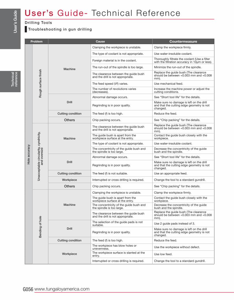
Use
r´s G
uide
www.tungaloyamerica.comG056
Tec
hnic
alre
fere
nce
User’s Guide- Technica l Reference
Troubleshooting in gun dri l l ing
Dri l l ing Tools
Problem Cause Countermeasure
Machine
Clamping the workpiece is unstable. Clamp the workpiece firmly.
The type of coolant is not appropriate. Use water-insoluble coolant.
Foreign material is in the coolant.Thoroughly filtrate the coolant (Use a filter with the filtration accuracy in 10μm or less).
The run-out of the spindle is too large. Minimize the run-out of the spindle.
The clearance between the guide bush and the drill is not appropriate.
Replace the guide bush (The clearance should be between +0.003 mm and +0.008 mm).
The feed speed (Vf) varies. Use mechanical feed.
The number of revolutions varies (decreases).
Increase the machine power or adjust the cutting conditions.
Drill
Abnormal damage occurs. See “Short tool life” for the details.
Regrinding is in poor quality. Make sure no damage is left on the drill and that the cutting edge geometry is not changed.
Cutting condition The feed (f) is too high. Reduce the feed.
Others Chip packing occurs. See “Chip packing” for the details.
Machine
The clearance between the guide bush and the drill is not appropriate.
Replace the guide bush (The clearance should be between +0.003 mm and +0.008 mm).
The guide bush is apart from the workpiece surface at the entry.
Contact the guide bush closely with the workpiece.
The type of coolant is not appropriate. Use water-insoluble coolant.
The concentricity of the guide bush and the spindle is too large.
Decrease the concentricity of the guide bush and the spindle.
Drill
Abnormal damage occurs. See “Short tool life” for the details.
Regrinding is in poor quality. Make sure no damage is left on the drill and that the cutting edge geometry is not changed.
Cutting condition The feed (f) is not suitable. Use an appropriate feed.
Workpiece Interrupted or cross drilling is required. Change the tool to a standard gundrill.
Others Chip packing occurs. See “Chip packing” for the details.
Machine
Clamping the workpiece is unstable. Clamp the workpiece firmly.
The guide bush is apart from the workpiece surface at the entry.
Contact the guide bush closely with the workpiece.
The concentricity of the guide bush and the spindle is too large.
Decrease the concentricity of the guide bush and the spindle.
The clearance between the guide bush and the drill is not appropriate.
Replace the guide bush (The clearance should be between +0.003 mm and +0.008 mm).
Drill
The selection of the guide pads is not suitable.
Use 2 guide pads instead of 3.
Regrinding is in poor quality. Make sure no damage is left on the drill and that the cutting edge geometry is not changed.
Cutting condition The feed (f) is too high. Reduce the feed.
Workpiece
The workpiece has blow holes or unevenness.
Use the workpiece without defect.
The workpiece surface is slanted at the entry.
Use low feed.
Interrupted or cross drilling is required. Change the tool to a standard gundrill.
Ro
ugh
surf
ace
finis
hU
nacc
epta
ble
circ
ular
ity, c
ynd
rici
ty,
and
ove
rsiz
e B
end
ing
of
hole
Ho
le a
ccur
acy
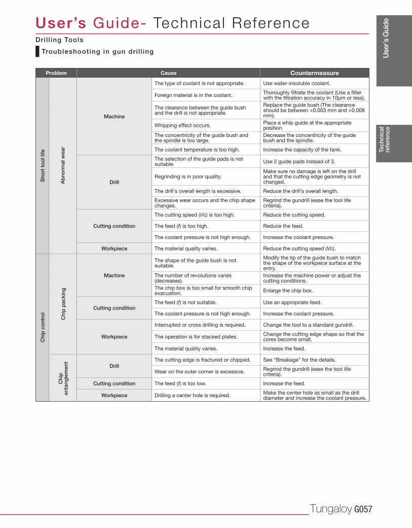
Use
r´s G
uide
Tungaloy G057
Tec
hnic
alre
fere
nce
User’s Guide- Technica l Reference
Troubleshooting in gun dri l l ing
Dri l l ing Tools
Problem Cause Countermeasure
Machine
The type of coolant is not appropriate. Use water-insoluble coolant.
Foreign material is in the coolant.Thoroughly filtrate the coolant (Use a filter with the filtration accuracy in 10μm or less).
The clearance between the guide bush and the drill is not appropriate.
Replace the guide bush (The clearance should be between +0.003 mm and +0.008 mm).
Whipping effect occurs. Place a whip guide at the appropriate position.
The concentricity of the guide bush and the spindle is too large.
Decrease the concentricity of the guide bush and the spindle.
The coolant temperature is too high. Increase the capacity of the tank.
Drill
The selection of the guide pads is not suitable.
Use 2 guide pads instead of 3.
Regrinding is in poor quality. Make sure no damage is left on the drill and that the cutting edge geometry is not changed.
The drill's overall length is excessive. Reduce the drill’s overall length.
Excessive wear occurs and the chip shape changes.
Regrind the gundrill (ease the tool life criteria).
Cutting condition
The cutting speed (Vc) is too high. Reduce the cutting speed.
The feed (f) is too high. Reduce the feed.
The coolant pressure is not high enough. Increase the coolant pressure.
Workpiece The material quality varies. Reduce the cutting speed (Vc).
Machine
The shape of the guide bush is not suitable.
Modify the tip of the guide bush to match the shape of the workpiece surface at the entry.
The number of revolutions varies (decreases).
Increase the machine power or adjust the cutting conditions.
The chip box is too small for smooth chip evacuation.
Enlarge the chip box.
Cutting conditionThe feed (f) is not suitable. Use an appropriate feed.
The coolant pressure is not high enough. Increase the coolant pressure.
Workpiece
Interrupted or cross drilling is required. Change the tool to a standard gundrill.
The operation is for stacked plates. Change the cutting edge shape so that the cores become small.
The material quality varies. Increase the feed.
DrillThe cutting edge is fractured or chipped. See “Breakage” for the details.
Wear on the outer corner is excessive.Regrind the gundrill (ease the tool life criteria).
Cutting condition The feed (f) is too low. Increase the feed.
Workpiece Drilling a center hole is required. Make the center hole as small as the drill diameter and increase the coolant pressure.
Sho
rt t
oo
l life
Chi
p c
ont
rol
Ab
norm
al w
ear
Chi
p p
acki
ngC
hip
enta
ngle
men
t
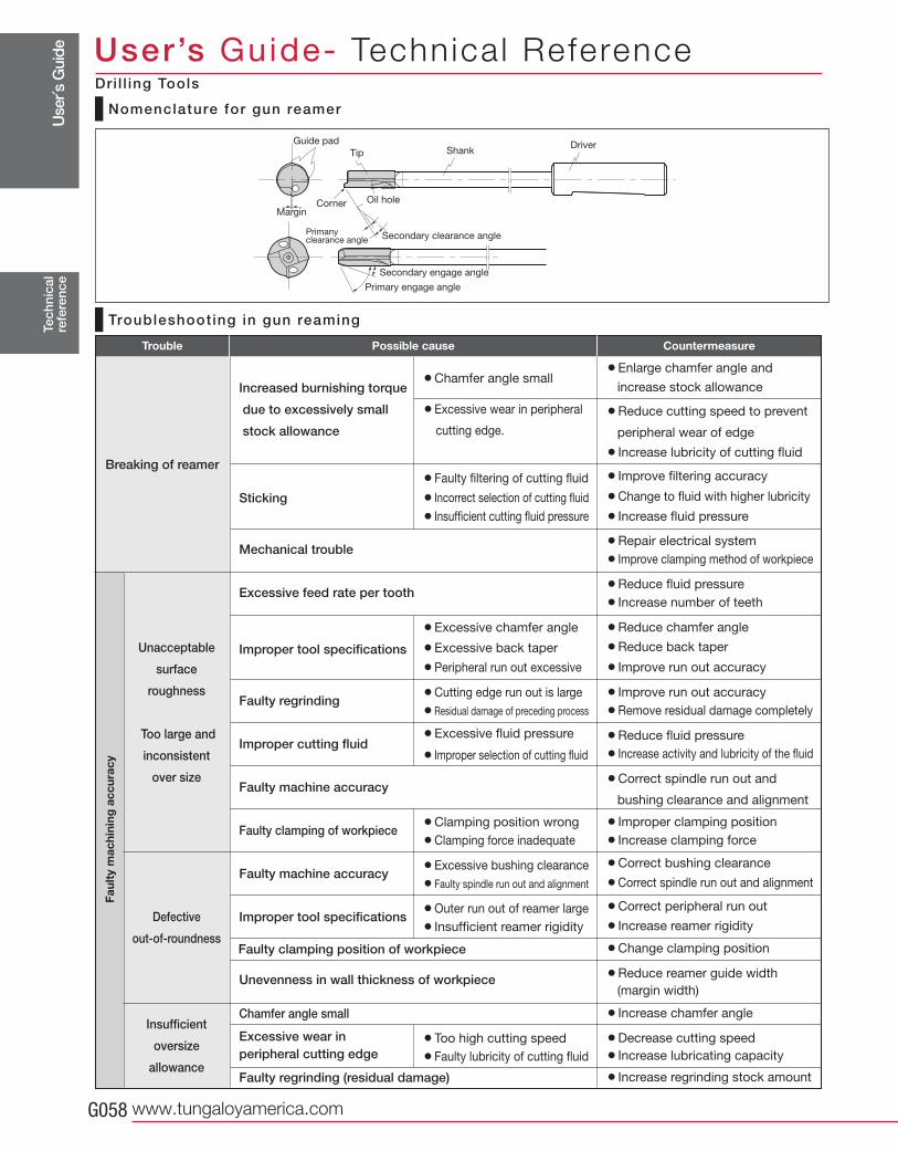
Use
r´s G
uide
www.tungaloyamerica.comG058
Tec
hnic
alre
fere
nce
User’s Guide- Technica l Reference
Trouble CountermeasurePossible cause
¡Enlarge chamfer angle and
increase stock allowance
¡Reduce cutting speed to prevent
peripheral wear of edge
¡Increase lubricity of cutting fluid
¡Improve filtering accuracy
¡Change to fluid with higher lubricity
¡Increase fluid pressure
¡Repair electrical system
¡Improve clamping method of workpiece
¡Reduce fluid pressure
¡Increase number of teeth
¡Reduce chamfer angle
¡Reduce back taper
¡Improve run out accuracy
¡Improve run out accuracy
¡Remove residual damage completely
¡Reduce fluid pressure
¡Increase activity and lubricity of the fluid
¡Correct spindle run out and
bushing clearance and alignment
¡Improper clamping position
¡Increase clamping force
¡Correct bushing clearance
¡Correct spindle run out and alignment
¡Correct peripheral run out
¡Increase reamer rigidity
¡Change clamping position
¡Reduce reamer guide width
(margin width)
¡Increase chamfer angle
¡Decrease cutting speed
¡Increase lubricating capacity
¡Increase regrinding stock amount
Increased burnishing torque
due to excessively small
stock allowance
Sticking
Mechanical trouble
Excessive feed rate per tooth
Improper tool specifications
Faulty regrinding
Improper cutting fluid
Faulty machine accuracy
Faulty clamping of workpiece
Faulty machine accuracy
Improper tool specifications
Unevenness in wall thickness of workpiece
Chamfer angle small
Excessive wear inperipheral cutting edge Faulty regrinding (residual damage)
Breaking of reamer
Faul
ty m
achi
ning
acc
urac
y
¡Chamfer angle small
¡Excessive wear in peripheral
cutting edge.
¡Faulty filtering of cutting fluid
¡Incorrect selection of cutting fluid
¡Insufficient cutting fluid pressure
¡Excessive chamfer angle
¡Excessive back taper
¡Peripheral run out excessive
¡Cutting edge run out is large
¡Residual damage of preceding process
¡Excessive fluid pressure
¡Improper selection of cutting fluid
¡Clamping position wrong
¡Clamping force inadequate
¡Excessive bushing clearance
¡Faulty spindle run out and alignment
¡Outer run out of reamer large
¡Insufficient reamer rigidity
¡Too high cutting speed
¡Faulty lubricity of cutting fluid
Unacceptable
surface
roughness
Too large and
inconsistent
over size
Defective
out-of-roundness
Insufficient
oversize
allowance
Faulty clamping position of workpiece
Nomenclature for gun reamer
Troubleshooting in gun reaming
Guide pad Driver
Primary engage angle
Shank
Secondary engage angle
Secondary clearance angle
Oil hole
Primany clearance angle
Corner
Tip
Margin
Dri l l ing Tools
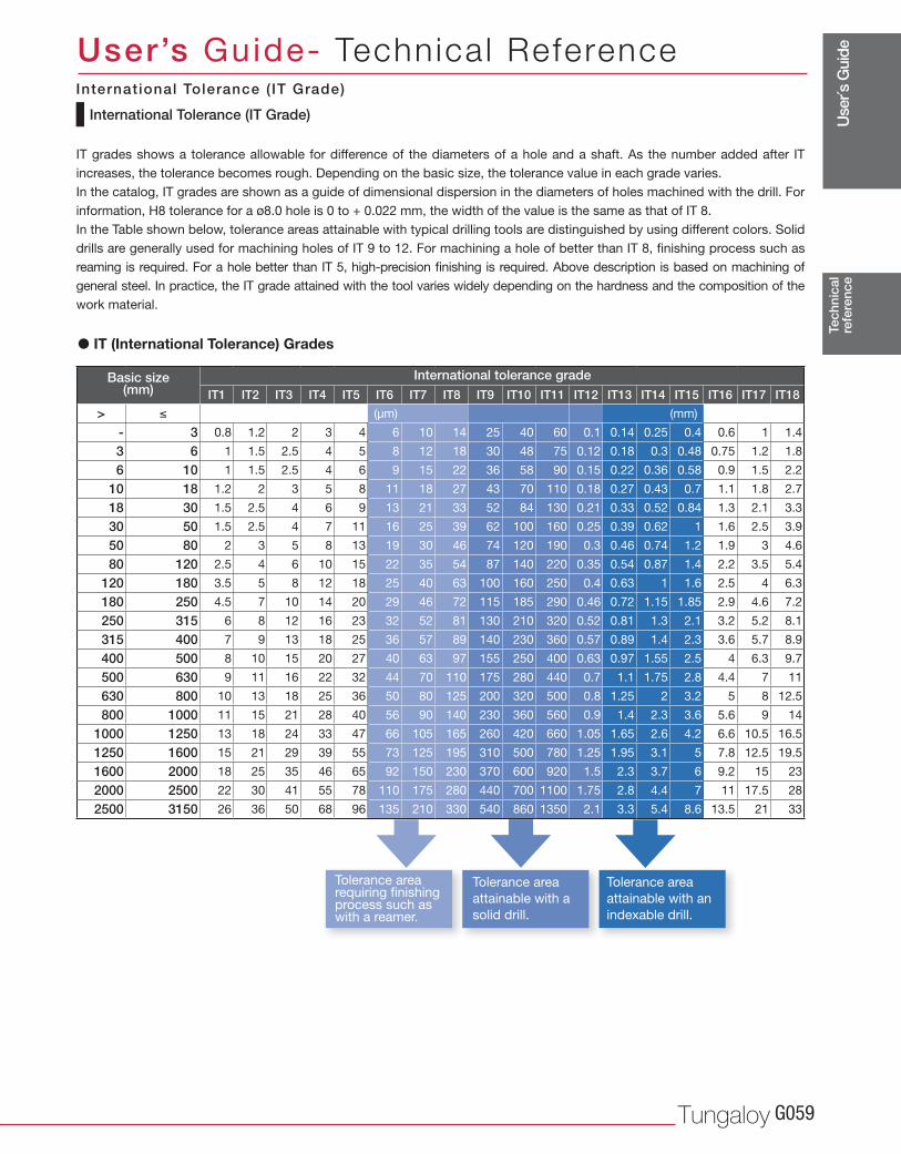
Use
r´s G
uide
Tungaloy G059
IT1 IT2 IT3 IT4 IT5 IT6 IT7 IT8 IT9 IT10 IT11 IT12 IT13 IT14 IT15 IT16 IT17 IT18
> (μm) (mm)
- 3 0.8 1.2 2 3 4 6 10 14 25 40 60 0.1 0.14 0.25 0.4 0.6 1 1.4
3 6 1 1.5 2.5 4 5 8 12 18 30 48 75 0.12 0.18 0.3 0.48 0.75 1.2 1.8
6 10 1 1.5 2.5 4 6 9 15 22 36 58 90 0.15 0.22 0.36 0.58 0.9 1.5 2.2
10 18 1.2 2 3 5 8 11 18 27 43 70 110 0.18 0.27 0.43 0.7 1.1 1.8 2.7
18 30 1.5 2.5 4 6 9 13 21 33 52 84 130 0.21 0.33 0.52 0.84 1.3 2.1 3.3
30 50 1.5 2.5 4 7 11 16 25 39 62 100 160 0.25 0.39 0.62 1 1.6 2.5 3.9
50 80 2 3 5 8 13 19 30 46 74 120 190 0.3 0.46 0.74 1.2 1.9 3 4.6
80 120 2.5 4 6 10 15 22 35 54 87 140 220 0.35 0.54 0.87 1.4 2.2 3.5 5.4
120 180 3.5 5 8 12 18 25 40 63 100 160 250 0.4 0.63 1 1.6 2.5 4 6.3
180 250 4.5 7 10 14 20 29 46 72 115 185 290 0.46 0.72 1.15 1.85 2.9 4.6 7.2
250 315 6 8 12 16 23 32 52 81 130 210 320 0.52 0.81 1.3 2.1 3.2 5.2 8.1
315 400 7 9 13 18 25 36 57 89 140 230 360 0.57 0.89 1.4 2.3 3.6 5.7 8.9
400 500 8 10 15 20 27 40 63 97 155 250 400 0.63 0.97 1.55 2.5 4 6.3 9.7
500 630 9 11 16 22 32 44 70 110 175 280 440 0.7 1.1 1.75 2.8 4.4 7 11
630 800 10 13 18 25 36 50 80 125 200 320 500 0.8 1.25 2 3.2 5 8 12.5
800 1000 11 15 21 28 40 56 90 140 230 360 560 0.9 1.4 2.3 3.6 5.6 9 14
1000 1250 13 18 24 33 47 66 105 165 260 420 660 1.05 1.65 2.6 4.2 6.6 10.5 16.5
1250 1600 15 21 29 39 55 73 125 195 310 500 780 1.25 1.95 3.1 5 7.8 12.5 19.5
1600 2000 18 25 35 46 65 92 150 230 370 600 920 1.5 2.3 3.7 6 9.2 15 23
2000 2500 22 30 41 55 78 110 175 280 440 700 1100 1.75 2.8 4.4 7 11 17.5 28
2500 3150 26 36 50 68 96 135 210 330 540 860 1350 2.1 3.3 5.4 8.6 13.5 21 33
Tec
hnic
alre
fere
nce
User’s Guide- Technica l Reference
International Tolerance (IT Grade)
IT grades shows a tolerance allowable for difference of the diameters of a hole and a shaft. As the number added after IT
increases, the tolerance becomes rough. Depending on the basic size, the tolerance value in each grade varies.
In the catalog, IT grades are shown as a guide of dimensional dispersion in the diameters of holes machined with the drill. For
information, H8 tolerance for a ø8.0 hole is 0 to + 0.022 mm, the width of the value is the same as that of IT 8.
In the Table shown below, tolerance areas attainable with typical drilling tools are distinguished by using different colors. Solid
drills are generally used for machining holes of IT 9 to 12. For machining a hole of better than IT 8, fi nishing process such as
reaming is required. For a hole better than IT 5, high-precision fi nishing is required. Above description is based on machining of
general steel. In practice, the IT grade attained with the tool varies widely depending on the hardness and the composition of the
work material.
� IT (International Tolerance) Grades
International tolerance gradeBasic size(mm)
Tolerance area requiring fi nishing process such as with a reamer.
Tolerance area
attainable with a
solid drill.
Tolerance area
attainable with an
indexable drill.
International Tolerance ( IT Grade)
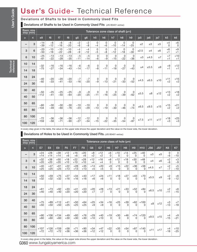
Use
r´s G
uide
www.tungaloyamerica.comG060
> e9 f6 f7 f8 g5 g6 h5 h6 h7 h8 h9 js5 js6 js7 k5 k6
- 3 −14−39
−6−12
−6−16
−6−20
−2−6
−2−8
0−4
0−6
0−10
0−14
0−25
±2 ±3 ±5+4
0+6
0
3 6 −20−50
−10−18
−10−22
−10−28
−4−9
−4−12
0−5
0−8
0−12
0−18
0−30
±2.5 ±4 ±6+6+1
+9+1
6 10 −25−61
−13−22
−13−28
−13−35
−5−11
−5−14
0−6
0−9
0−15
0−22
0−36
±3 ±4.5 ±7+7+1
+10+1
10 14−32−75
−16−27
−16−34
−16−43
−6−14
−6−17
0−8
0−11
0−18
0−27
0−43
±4 ±5.5 ±9+9+1
+12+1
14 18
18 24−40−92
−20−33
−20−41
−20−53
−7−16
−7−20
0−9
0−13
0−21
0−33
0−52
±4.5 ±6.5 ±10+11+2
+15+2
24 30
30 40−50
−112−25−41
−25−50
−25−64
−9−20
−9−25
0−11
0−16
0−25
0−39
0−62
±5.5 ±8 ±12+13+2
+18+2
40 50
50 65−60
−134−30−49
−30−60
−30−76
−10−23
−10−29
0−13
0−19
0−30
0−46
0−74
±6.5 ±9.5 ±15+15+2
+21+2
65 80
80 100−72
−159−36−58
−36−71
−36−90
−12−27
−12−34
0−15
0−22
0−35
0−54
0−87
±7.5 ±11 ±17+18+3
+25+3
100 120
> E7 E8 E9 F6 F7 F8 G6 G7 H6 H7 H8 H9 H10 JS6 JS7 K6 K7
- 3 +24+14
+28+14
+39+14
+12+6
+16+6
+20+6
+8+2
+12+2
+60
+100
+140
+250
+400
±3 ±50
−60
−10
3 6 +32+20
+38+20
+50+20
+18+10
+22+10
+28+10
+12 +4
+16+4
+80
+120
+180
+300
+480
±4 ±6+2−6
+3−9
6 10 +40+25
+47+25
+61+25
+22+13
+28+13
+35+13
+14+5
+20+5
+90
+150
+220
+360
+580
±4.5 ±7+2−7
+5−10
10 14+50+32
+59+32
+75+32
+27+16
+34+16
+43+16
+17+6
+24+6
+110
+180
+270
+430
+700
±5.5 ±9+2−9
+6−12
14 18
18 24+61+40
+73+40
+92+40
+33+20
+41+20
+53+20
+20+7
+28+7
+130
+210
+330
+520
+840
±6.5 ±10+2
−11+6
−1524 30
30 40+75+50
+89+50
+112+50
+41+25
+50+25
+64+25
+25+9
+34+9
+160
+250
+390
+620
+1000
±8 ±12+3
−13+7
−1840 50
50 65+90+60
+106+60
+134+60
+49+30
+60+30
+76+30
+29+10
+40+10
+190
+300
+460
+740
+1200
±9.5 ±15+4
−15+9
−2165 80
80 100+107+72
+126+72
+159+72
+58+36
+71+36
+90+36
+34+12
+47+12
+220
+350
+540
+870
+1400
±11 ±17+4
−18+10−25
100 120
Tec
hnic
alre
fere
nce
User’s Guide- Technica l Reference
Tolerance zone class of shaft (μm)Basic size step (mm)
Tolerance zone class of hole (μm)Basic size step (mm)
Deviations of Shafts to be Used in Commonly Used Fits (JIS B0401 extrac)
In every step given in the table, the value on the upper side shows the upper deviation and the value on the lower side, the lower deviation.
Deviations of Holes to be Used in Commonly Used Fits. (JIS B0401 extrac)
In every step given in the table, the value on the upper side shows the upper deviation and the value on the lower side, the lower deviation.
Deviat ions of Shafts to be Used in Commonly Used Fits
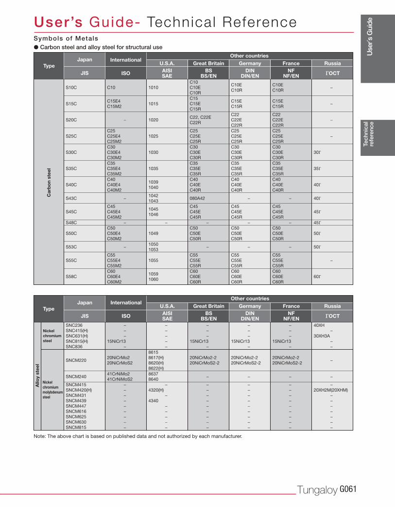
Use
r´s G
uide
Tungaloy G061
S10C
S15CC15E4
C15M2
− −
1015C15E
C15R−
C15
C15E
C15R
C15E
C15R
C10 1010
C10
C10E
C10R
C10E
C10R−
S25C
C25
C25E4
C25M2
1025 −
C25
C25E
C25R
C25
C25E
C25R
C25
C25E
C25R
S35C
C35
C35E4
C35M2
1035
C35
C35E
C35R
C35
C35E
C35R
C35
C35E
C35R
S30C
C30
C30E4
C30M2
1030
C30
C30E
C30R
C30
C30E
C30R
C30
C30E
C30R
35Γ
S45C
C45
C45E4
C45M2
1045
1046
C45
C45E
C45R
C45
C45E
C45R
C45
C45E
C45R
45Γ
S58C
C60
C60E4
C60M2
1059
1060
C60
C60E
C60R
C60
C60E
C60R
C60
C60E
C60R
60Γ
S48C −− −− − 45Γ
30Γ
S20C 1020C22, C22E
C22R
C22
C22E
C22R
C22
C22E
C22R
S40C1039
1040
C40
C40E
C40R
C40
C40E4
C40M2
C40
C40E
C40R
C40
C40E
C40R
40Γ
S50C 1049
C50
C50E
C50R
C50
C50E4
C50M2
C50
C50E
C50R
C50
C50E
C50R
50Γ
S55C 1055
C55
C55E
C55R
C55
C55E4
C55M2
C55
C55E
C55R
C55
C55E
C55R
−
S43C −
− − − −
− −1042
1043080A42 40Γ
S53C1050
105350Γ
SNC236
SNC415(H)
SNC631(H)
SNC815(H)
SNC836
−
−
−
15NiCr13
−
−
−
−
−
−
−
−
−
15NiCr13
−
−
−
−
15NiCr13
−
40XH
−
30XH3A
−
−
−
−
−
15NiCr13
−
SNCM415
SNCM420(H)
SNCM431
SNCM439
SNCM447
SNCM616
SNCM625
SNCM630
SNCM815
−
−
−
−
−
−
−
−
−
−
4320(H)
−
4340
−
−
−
−
−
−
−
−
−
−
−
−
−
−
−
−
−
−
−
−
−
−
−
−
20XH2M(20XHM)
−
−
−
−
−
−
−
−
−
−
−
−
−
−
−
−
SNCM22020NiCrMo2
20NiCrMoS2
8615
8617(H)
8620(H)
8622(H)
20NiCrMo2-2
20NiCrMoS2-2
20NiCrMo2-2
20NiCrMoS2-2−
20NiCrMo2-2
20NiCrMoS2-2
SNCM24041CrNiMo2
41CrNiMoS2
8637
8640− − −−
C10E
C10R
JIS ISO AISISAE
BSBS/EN
DINDIN/EN
NFNF/EN гOCT
JIS ISO AISISAE
BSBS/EN
DINDIN/EN
NFNF/EN гOCT
Tec
hnic
alre
fere
nce
User’s Guide- Technica l Reference
� Carbon steel and alloy steel for structural use
Type
Car
bo
n st
eel
Allo
y st
eel
Nickel chromium steel
Nickel chromium molybdenum steel
Japan InternationalU.S.A. Great Britain Germany France Russia
TypeJapan
U.S.A. Great Britain Germany France Russia
Other countries
InternationalOther countries
Note: The above chart is based on published data and not authorized by each manufacturer.
Symbols of Metals
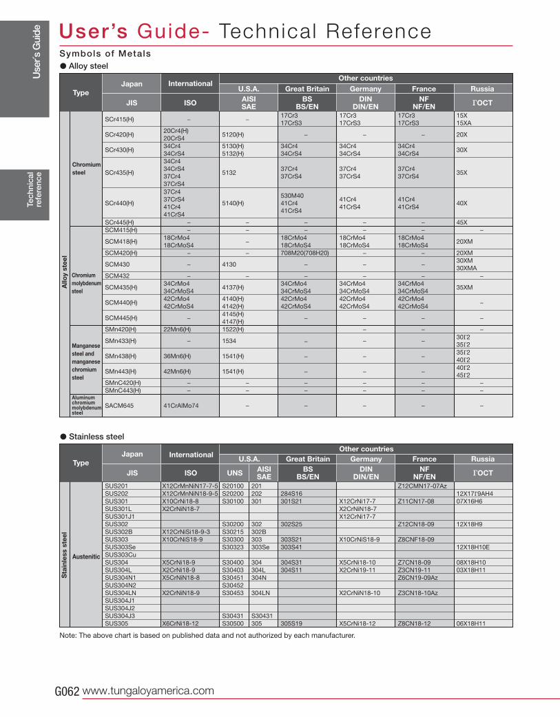
Use
r´s G
uide
www.tungaloyamerica.comG062
SUS201
SUS202
SUS301
SUS301L
SUS301J1
SUS302
SUS302B
SUS303
SUS303Se
SUS303Cu
SUS304
SUS304L
SUS304N1
SUS304N2
SUS304LN
SUS304J1
SUS304J2
SUS304J3
SUS305
X12CrMnNiN17-7-5
X12CrMnNiN18-9-5
X10CrNi18-8
X2CrNiN18-7
X12CrNiSi18-9-3
X10CrNiS18-9
X5CrNi18-9
X2CrNi18-9
X5CrNiN18-8
X2CrNiN18-9
X6CrNi18-12
S20100
S20200
S30100
S30200
S30215
S30300
S30323
S30400
S30403
S30451
S30452
S30453
S30431
S30500
201
202
301
302
302B
303
303Se
304
304L
304N
304LN
S30431
305
284S16
301S21
302S25
303S21
303S41
304S31
304S11
305S19
X12CrNi17-7
X2CrNiN18-7
X12CrNi17-7
X10CrNiS18-9
X5CrNi18-10
X2CrNi19-11
X2CrNiN18-10
X5CrNi18-12
12X17Γ9AH4
07X16H6
12X18H9
12X18H10E
08X18H10
03X18H11
06X18H11
Z12CMN17-07Az
Z11CN17-08
Z12CN18-09
Z8CNF18-09
Z7CN18-09
Z3CN19-11
Z6CN19-09Az
Z3CN18-10Az
Z8CN18-12
SCr415(H) − −17Cr3
17CrS3
17Cr3
17CrS3
15X
15XA
17Cr3
17CrS3
SCr420(H)20Cr4(H)
20CrS45120(H) − − 20X−
SCr430(H)34Cr4
34CrS4
5130(H)
5132(H)
34Cr4
34CrS4
34Cr4
34CrS430X
34Cr4
34CrS4
SMn433(H) − 1534 −30Γ2
35Γ2−
SMn438(H) 36Mn6(H) 1541(H) −35Γ2
40Γ2−
SMn443(H) 42Mn6(H) 1541(H) − −40Γ2
45Γ2−
SCM418(H)18CrMo4
18CrMoS4−
18CrMo4
18CrMoS4
18CrMo4
18CrMoS420XM
18CrMo4
18CrMoS4
SCM435(H)34CrMo4
34CrMoS44137(H)
34CrMo4
34CrMoS4
34CrMo4
34CrMoS435XM
34CrMo4
34CrMoS4
SCM445(H) −4145(H)
4147(H)−
−
−
− −−
SCM430 − 4130 − −30XM
30XMA−
SCM415(H) − − − − −−
SCr435(H)
34Cr4
34CrS4
37Cr4
37CrS4
513237Cr4
37CrS4
37Cr4
37CrS435X
37Cr4
37CrS4
SCM440(H)42CrMo4
42CrMoS4
4140(H)
4142(H)
42CrMo4
42CrMoS4
42CrMo4
42CrMoS4−
42CrMo4
42CrMoS4
SCr440(H)
37Cr4
37CrS4
41Cr4
41CrS4
5140(H)
530M40
41Cr4
41CrS4
41Cr4
41CrS440X
41Cr4
41CrS4
SCr445(H) − − − − 45X−
SCM420(H) − − 708M20(708H20) − 20XM−
SCM432 − − − − −−
SMn420(H) 22Mn6(H) 1522(H) − −−
SMnC420(H) − − − − −−
SMnC443(H) − − − − −−
SACM645 41CrAlMo74 − − − −−
JIS ISO AISISAE
BSBS/EN
DINDIN/EN
NFNF/EN гOCT
JIS ISO UNS AISISAE
BSBS/EN
DINDIN/EN
NFNF/EN гOCT
Tec
hnic
alre
fere
nce
User’s Guide- Technica l Reference
Austenitic
Sta
inle
ss s
teel
Chromium molybdenum steel
Chromium steel
Manganese steel and manganese chromium steel
Allo
y st
eel
� Alloy steel
� Stainless steel
TypeJapan
U.S.A. Great Britain Germany France Russia
TypeJapan
U.S.A. Great Britain Germany France Russia
Aluminumchromiummolybdenumsteel
InternationalOther countries
InternationalOther countries
Note: The above chart is based on published data and not authorized by each manufacturer.
Symbols of Metals
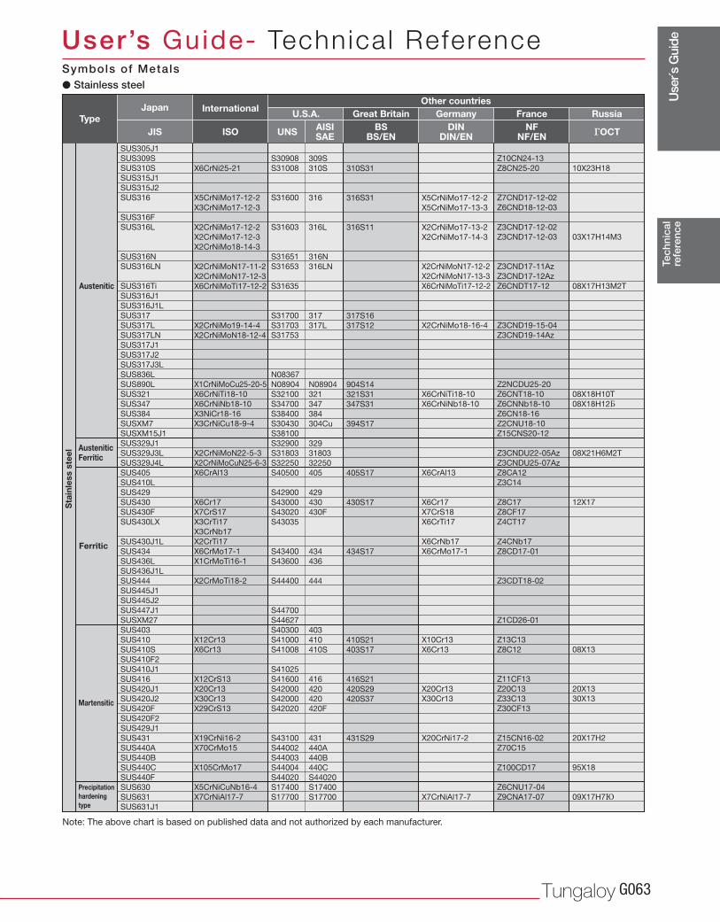
Use
r´s G
uide
Tungaloy G063
SUS305J1
SUS309S
SUS310S
SUS315J1
SUS315J2
SUS316
SUS316F
SUS316L
SUS316N
SUS316LN
SUS316Ti
SUS316J1
SUS316J1L
SUS317
SUS317L
SUS317LN
SUS317J1
SUS317J2
SUS317J3L
SUS836L
SUS890L
SUS321
SUS347
SUS384
SUSXM7
SUSXM15J1
SUS329J1
SUS329J3L
SUS329J4L
SUS405
SUS410L
SUS429
SUS430
SUS430F
SUS430LX
SUS430J1L
SUS434
SUS436L
SUS436J1L
SUS444
SUS445J1
SUS445J2
SUS447J1
SUSXM27
SUS403
SUS410
SUS410S
SUS410F2
SUS410J1
SUS416
SUS420J1
SUS420J2
SUS420F
SUS420F2
SUS429J1
SUS431
SUS440A
SUS440B
SUS440C
SUS440F
SUS630
SUS631
SUS631J1
X6CrNi25-21
X5CrNiMo17-12-2
X3CrNiMo17-12-3
X2CrNiMo17-12-2
X2CrNiMo17-12-3
X2CrNiMo18-14-3
X2CrNiMoN17-11-2
X2CrNiMoN17-12-3
X6CrNiMoTi17-12-2
X2CrNiMo19-14-4
X2CrNiMoN18-12-4
X1CrNiMoCu25-20-5
X6CrNiTi18-10
X6CrNiNb18-10
X3NiCr18-16
X3CrNiCu18-9-4
X2CrNiMoN22-5-3
X2CrNiMoCuN25-6-3
X6CrAl13
X6Cr17
X7CrS17
X3CrTi17
X3CrNb17
X2CrTi17
X6CrMo17-1
X1CrMoTi16-1
X2CrMoTi18-2
X12Cr13
X6Cr13
X12CrS13
X20Cr13
X30Cr13
X29CrS13
X19CrNi16-2
X70CrMo15
X105CrMo17
X5CrNiCuNb16-4
X7CrNiAl17-7
S30908
S31008
S31600
S31603
S31651
S31653
S31635
S31700
S31703
S31753
N08367
N08904
S32100
S34700
S38400
S30430
S38100
S32900
S31803
S32250
S40500
S42900
S43000
S43020
S43035
S43400
S43600
S44400
S44700
S44627
S40300
S41000
S41008
S41025
S41600
S42000
S42000
S42020
S43100
S44002
S44003
S44004
S44020
S17400
S17700
309S
310S
316
316L
316N
316LN
317
317L
N08904
321
347
384
304Cu
329
31803
32250
405
429
430
430F
434
436
444
403
410
410S
416
420
420
420F
431
440A
440B
440C
S44020
S17400
S17700
310S31
316S31
316S11
317S16
317S12
904S14
321S31
347S31
394S17
405S17
430S17
434S17
410S21
403S17
416S21
420S29
420S37
431S29
X5CrNiMo17-12-2
X5CrNiMo17-13-3
X2CrNiMo17-13-2
X2CrNiMo17-14-3
X2CrNiMoN17-12-2
X2CrNiMoN17-13-3
X6CrNiMoTi17-12-2
X2CrNiMo18-16-4
X6CrNiTi18-10
X6CrNiNb18-10
X6CrAl13
X6Cr17
X7CrS18
X6CrTi17
X6CrNb17
X6CrMo17-1
X10Cr13
X6Cr13
X20Cr13
X30Cr13
X20CrNi17-2
X7CrNiAl17-7
10X23H18
03X17H14M3
08X17H13M2T
08X18H10T
08X18H12Б
08X21H6M2T
12X17
08X13
20X13
30X13
20X17H2
95X18
09X17H7Ю
Z10CN24-13
Z8CN25-20
Z7CND17-12-02
Z6CND18-12-03
Z3CND17-12-02
Z3CND17-12-03
Z3CND17-11Az
Z3CND17-12Az
Z6CNDT17-12
Z3CND19-15-04
Z3CND19-14Az
Z2NCDU25-20
Z6CNT18-10
Z6CNNb18-10
Z6CN18-16
Z2CNU18-10
Z15CNS20-12
Z3CNDU22-05Az
Z3CNDU25-07Az
Z8CA12
Z3C14
Z8C17
Z8CF17
Z4CT17
Z4CNb17
Z8CD17-01
Z3CDT18-02
Z1CD26-01
Z13C13
Z8C12
Z11CF13
Z20C13
Z33C13
Z30CF13
Z15CN16-02
Z70C15
Z100CD17
Z6CNU17-04
Z9CNA17-07
JIS UNS AISISAE
BSBS/EN
DINDIN/EN
NFNF/EN гOCTISO
Tec
hnic
alre
fere
nce
User’s Guide- Technica l Reference
Austenitic
AusteniticFerritic
Sta
inle
ss s
teel
Ferritic
Martensitic
Precipitationhardening type
� Stainless steel
TypeJapan
U.S.A. Great Britain Germany France RussiaInternationalOther countries
Note: The above chart is based on published data and not authorized by each manufacturer.
Symbols of Metals
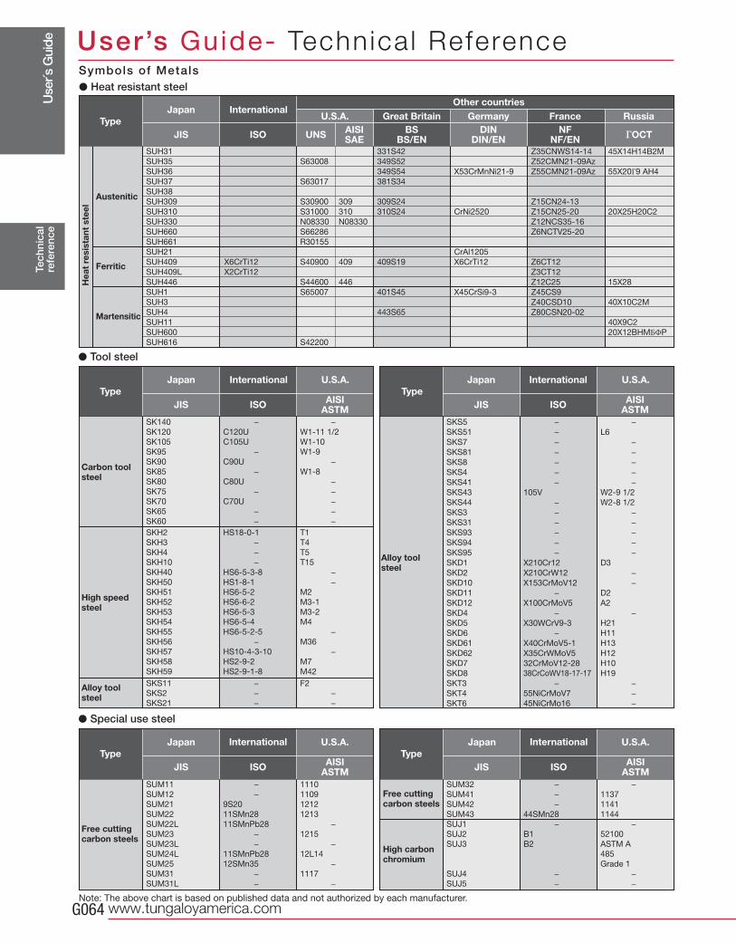
Use
r´s G
uide
www.tungaloyamerica.comG064
SK140
SK120
SK105
SK95
SK90
SK85
SK80
SK75
SK70
SK65
SK60
−
C120U
C105U
−
C90U
−
C80U
−
C70U
−
−
−
W1-11 1/2
W1-10
W1-9
−
W1-8
−
−
−
−
−
SKH2
SKH3
SKH4
SKH10
SKH40
SKH50
SKH51
SKH52
SKH53
SKH54
SKH55
SKH56
SKH57
SKH58
SKH59
SKS11
SKS2
SKS21
HS18-0-1
−
−
−
HS6-5-3-8
HS1-8-1
HS6-5-2
HS6-6-2
HS6-5-3
HS6-5-4
HS6-5-2-5
−
HS10-4-3-10
HS2-9-2
HS2-9-1-8
−
−
−
T1
T4
T5
T15
−
−
M2
M3-1
M3-2
M4
−
M36
−
M7
M42
F2
−
−
SKS5
SKS51
SKS7
SKS81
SKS8
SKS4
SKS41
SKS43
SKS44
SKS3
SKS31
SKS93
SKS94
SKS95
SKD1
SKD2
SKD10
SKD11
SKD12
SKD4
SKD5
SKD6
SKD61
SKD62
SKD7
SKD8
SKT3
SKT4
SKT6
−
−
−
−
−
−
−
105V
−
−
−
−
−
−
X210Cr12
X210CrW12
X153CrMoV12
−
X100CrMoV5
−
X30WCrV9-3
−
X40CrMoV5-1
X35CrWMoV5
32CrMoV12-28
38CrCoWV18-17-17
−
55NiCrMoV7
45NiCrMo16
−
L6
−
−
−
−
−
W2-9 1/2
W2-8 1/2
−
−
−
−
−
D3
−
−
D2
A2
−
H21
H11
H13
H12
H10
H19
−
−
−
SUH31
SUH35
SUH36
SUH37
SUH38
SUH309
SUH310
SUH330
SUH660
SUH661
SUH21
SUH409
SUH409L
SUH446
SUH1
SUH3
SUH4
SUH11
SUH600
SUH616
X6CrTi12
X2CrTi12
S63008
S63017
S30900
S31000
N08330
S66286
R30155
S40900
S44600
S65007
S42200
309
310
N08330
409
446
331S42
349S52
349S54
381S34
309S24
310S24
409S19
401S45
443S65
X53CrMnNi21-9
CrNi2520
CrAl1205
X6CrTi12
X45CrSi9-3
45X14H14B2M
55X20Г9 AH4
20X25H20C2
15X28
40X10C2M
40X9C2
20X12BHMБΦP
Z35CNWS14-14
Z52CMN21-09Az
Z55CMN21-09Az
Z15CN24-13
Z15CN25-20
Z12NCS35-16
Z6NCTV25-20
Z6CT12
Z3CT12
Z12C25
Z45CS9
Z40CSD10
Z80CSN20-02
SUM11
SUM12
SUM21
SUM22
SUM22L
SUM23
SUM23L
SUM24L
SUM25
SUM31
SUM31L
−
−
9S20
11SMn28
11SMnPb28
−
−
11SMnPb28
12SMn35
−
−
1110
1109
1212
1213
−
1215
−
12L14
−
1117
−
SUM32
SUM41
SUM42
SUM43
SUJ1
SUJ2
SUJ3
SUJ4
SUJ5
−
−
−
44SMn28
−
B1
B2
−
−
−
1137
1141
1144
−
52100
ASTM A
485
Grade 1
−
−
UNS AISISAE
BSBS/EN
DINDIN/EN
NFNF/EN гOCTJIS ISO
JIS ISO AISIASTM JIS ISO AISI
ASTM
JIS ISO AISIASTM JIS ISO AISI
ASTM
Tec
hnic
alre
fere
nce
User’s Guide- Technica l Reference
TypeJapan
U.S.A. Great Britain Germany France Russia
TypeJapan U.S.A.
TypeJapan U.S.A.
TypeJapan U.S.A.
TypeJapan U.S.A.
� Tool steel
� Special use steel
Austenitic
Ferritic
Martensitic
Hea
t re
sist
ant
stee
l
Carbon toolsteel
Free cutting carbon steels
High speedsteel
Alloy toolsteel
Free cutting carbon steels
High carbonchromium
Alloy toolsteel
InternationalOther countries
International International
International International
Note: The above chart is based on published data and not authorized by each manufacturer.
Symbols of Metals� Heat resistant steel
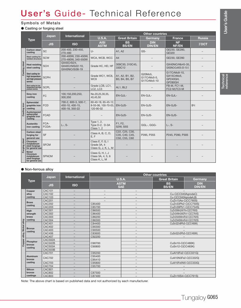
Use
r´s G
uide
Tungaloy G065
SC200-400, 230-450,
270-480U- A1, A2 GS-
GE230, GE280,
GE320
SCW200-400W, 230-450W,
270-480W, 340-550WWCA, WCB, WCC A4 − GE230, GE280
SCPL −Grade LCB, LC1,
LC2, LC3AL1, BL2 −
FB-M, FC1-M,
FC2-M,FC3-M
FCD
700-2, 600-3, 500-7,
450-10, 400-15,
400-18, 350-22
60-40-18, 65-45-12,
8-55-06, 100-70-03,
120-90-02
EN-GJS- EN-GJS- EN-GJS- BЧ
FC100,150,200,250,
300,350
No.20,25,30,35,
40,45,50EN-GJL- EN-GJL- EN-GJL-
FCAD −
L-, S-
−
Type 1, 2,
Type D-2, D-3A
Class 1, 2
EN-GJS- EN-GJS- EN-GJS-
FCA-
FCDA-
F1, F2,
S2W, S5S GGL-, GGG- L-, S-
−Class A, B, C, D,
E, FSF
C22, C25, C30,
C35, C40, C45,
C50, C55, C60
P285, P355 P245, P280, P305
−
Class E, F, G, I
Grade 3A, 4
Class G, J, K, L, M
SFCM − − − −
−
Class G, H, I, J
Class 3A, 4, 5, 6
Class K, L, M
SFNCM − − − −
−
−
−
−
−
−
−
−
−SCH
GX40CrSi24,
GX40CrNiSi22-10,
GX40NiCrSi38-19
Grade HC, HD, HF309C30, 310C45,
330C12−
GX40NiCrNb45-35,
GX50NiCrCoW35-25-15-5
SCPH −Grade WC1, WC6,
WC9
A1, A2, B1, B2,
B3, B4, B5, B7
G20Mo5,
G17CrMo5-5,
G17CrMo5-10
G17CrMo9-10,
GX15CrMo5,
GP240GH,
GP280GH
CAC101
CAC102
CAC103
CAC201
CAC202
CAC203
CAC301
CAC302
CAC303
CAC304
CAC401
CAC402
CAC403
CAC406
CAC407
CAC502A
CAC502B
CAC503A
CAC503B
CAC701
CAC702
CAC703
CAC704
CAC801
CAC802
CAC803
−
−
−
−
−
−
−
−
−
−
−
−
−
−
−
−
−
−
−
−
−
−
−
−
−
−
−
−
−
−
−
C85400
C85700
C86500
C86400
C86200
C86300
C84400
C90300
C90500
C83600
C92200
C90700
C90800
C95200
C95400
C95410
C95800
C95700
−
C87500
C87400
−
−
−
−
−
−
−
−
−
−
−
−
−
−
−
−
−
−
−
−
−
−
−
−
−
−
−
−
Cu-C(CC040AgrodeC)
Cu-C(CC040AgrodeA,B)
CuZn15As-C(CC760S)
CuZn33Pb2-C(CC750S)
CuZn39Pb1-C(CC754S)
CuZn35Mn2Al1Fe-C(CC765S)
CuZn34Mn3Al2Fe1-C(CC764S)
CuZn25Al5Mn4Fe3-C(CC762S)
CuZn25Al5Mn4Fe3-C(CC762S)
CuSn3Zn8Pb5-C(CC490K)
−
−
CuSn5Zn5Pb5-C(CC490K)
−
CuSn10-C(CC480K)
CuSn12-C(CC483K)
CuAl10Fe2-C(CC331G)
CuAl10Ni3Fe2-C(CC332G)
CuAl10Fe5Ni5-C(CC333G)
−
−
−
CuZn16Si4-C(CC761S)
JIS ISO AISIASTM
BSBS/EN
DINDIN/EN
NFNF/EN гOCT
ASTMSAE
BSBS/EN
DINDIN/ENJIS ISO
Tec
hnic
alre
fere
nce
User’s Guide- Technica l Reference
� Casting or forging steel
� Non-ferrous alloy
TypeJapan
U.S.A. Great Britain Germany France Russia
TypeJapan
U.S.A. Great Britain Germany
Carbon steel casting
Steel casting for welded structure
Steel casting for low temperature and high pressure service
Heat resisting steel casting
Steel casting for high temperature and high pressure service
Cas
ting
ste
el
Copper alloy casting
Brass casting
Silicon bronze castings
High strength brass casting
Phosphor bronze casting
Bronze casting
Aluminum bronze casting
Co
pp
er a
lloy,
Nic
kel a
lloy
Grey ironcasting
Spheroidal graphite iron casting
Austempered spheroidal graphite iron casting
Austenitic iron casting
Cas
ting
iro
n
Carbon steel forging for general useChromium molybdenum steel forgings for general use
Nickel Chromium molybdenum steel forgings for general use
Forg
ing
ste
el
InternationalOther countries
InternationalOther countries
Note: The above chart is based on published data and not authorized by each manufacturer.
Symbols of Metals
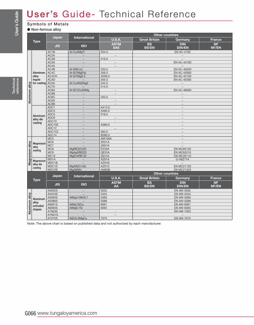
Use
r´s G
uide
www.tungaloyamerica.comG066
AC1B
AC2A
AC2B
AC3A
AC4A
AC4B
AC4C
AC4CH
AC4D
AC5A
AC7A
AC8A
AC8B
AC8C
AC9A
AC9B
ADC1
ADC3
ADC5
ADC6
ADC10
ADC10Z
ADC12
ADC12Z
ADC14
MC5
MC6
MC7
MC8
MC9
MC10
MD1A
MDC1B
MDC1D
MDC2B
Al-Cu4MgTi
−
−
−
−
Al-Si8Cu3
Al-Si7Mg(Fe)
Al-Si7Mg0.3
−
Al-Cu4Ni2Mg2
−
Al-Si12CuNiMg
−
−
−
−
−
−
−
−
−
−
−
−
−
−
−
−
MgRE3Zn2Zr
MgAg3RE2Zr
MgZn4RE1Zr
−
−
MgAl9Zn1(A)
MgAl6Mn
204.0
−
319.0
−
−
333.0
356.0
A356.0
355.0
242.0
514.0
−
−
332.0
−
−
A413.0
A360.0
518.0
−
−
A380.0
−
383.0
B390.0
AM100A
ZK51A
ZK61A
EZ33A
QE22A
ZE41A
AZ91A
AZ91B
AZ91D
AM60B
EN AC-2100
−
−
EN AC-44100
−
EN AC-46200
EN AC-42000
EN AC-42100
EN AC-45300
−
−
EN AC-48000
−
−
−
−
−
−
−
−
−
−
−
−
−
−
−
−
EN MC65120
EN MC65210
EN MC35110
G-A9Z1Y4
−
EN MC21120
EN MC21320
A5052S
A5454S
A5083S
A5086S
A6061S
A6063S
A7003S
A7N01S
A7075S
−
−
AlMg4.5Mn0.7
−
AlMg1SiCu
AlMg0.7Si
−
−
AlZn5.5MgCu
5052
5454
5083
5086
6061
6063
−
−
7075
EN AW-5052
EN AW-5454
EN AW-5083
EN AW-5086
EN AW-6061
EN AW-6063
EN AW-7003
−
EN AW-7075
JIS ISO ASTMSAE
BSBS/EN
DINDIN/EN
NFNF/EN
JIS ISO ASTMAA
BSBS/EN
DINDIN/EN
NFNF/EN
Tec
hnic
alre
fere
nce
User’s Guide- Technica l Reference
TypeJapan
U.S.A. Great Britain Germany France
TypeJapan
U.S.A. Great Britain Germany France
Aluminum alloy ingots for casting
Aluminum alloy die casting
Magnesium alloy casting
Aluminum alloy extruded shapes
Magnesium alloy die casting
Alu
min
um a
lloy
Mag
nesi
um a
lloy
Alu
min
um a
lloy
InternationalOther countries
InternationalOther countries
Note: The above chart is based on published data and not authorized by each manufacturer.
Symbols of Metals� Non-ferrous alloy
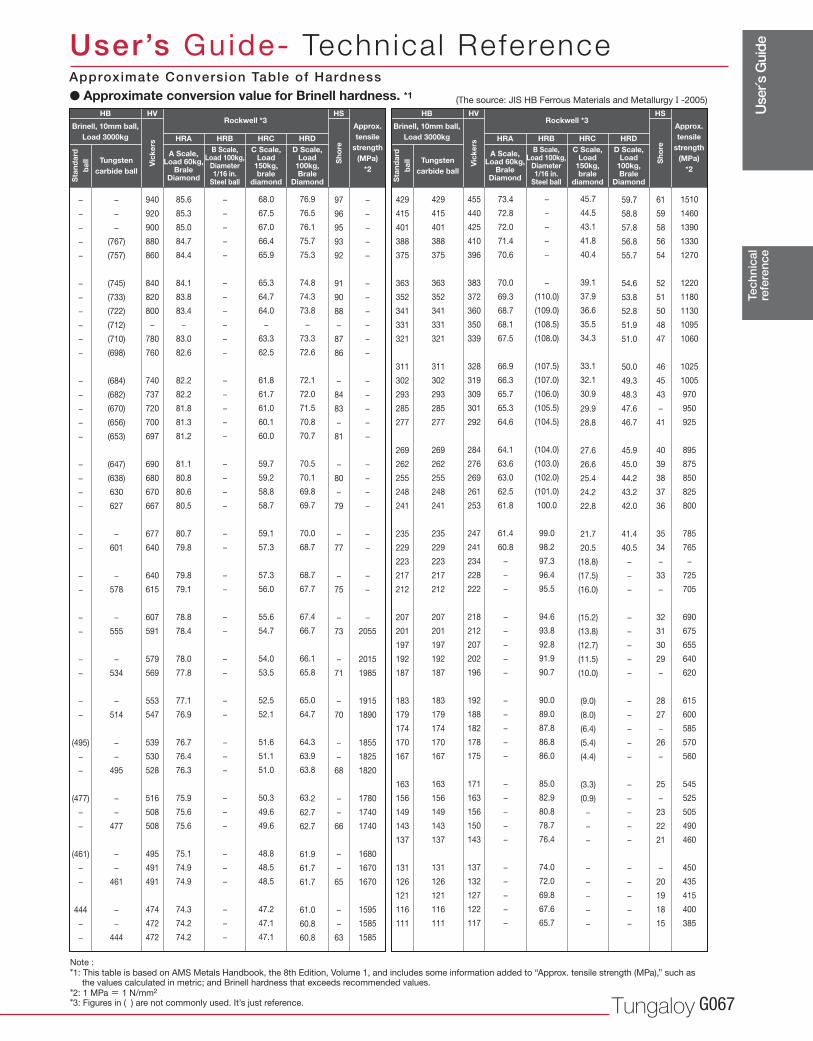
Use
r´s G
uide
Tungaloy G067
−
−
−
−
−
−
−
−
−
−
−
−
−
−
−
−
−
−
−
−
−
−
−
−
−
−
−
−
−
−
(495)
−
−
(477)
−
−
(461)
−
−
444
−
−
−
−
−
(767)
(757)
(745)
(733)
(722)
(712)
(710)
(698)
(684)
(682)
(670)
(656)
(653)
(647)
(638)
630
627
−
601
−
578
−
555
−
534
−
514
−
−
495
−
−
477
−
−
461
−
−
444
940
920
900
880
860
840
820
800
−
780
760
740
737
720
700
697
690
680
670
667
677
640
640
615
607
591
579
569
553
547
539
530
528
516
508
508
495
491
491
474
472
472
85.6
85.3
85.0
84.7
84.4
84.1
83.8
83.4
−
83.0
82.6
82.2
82.2
81.8
81.3
81.2
81.1
80.8
80.6
80.5
80.7
79.8
79.8
79.1
78.8
78.4
78.0
77.8
77.1
76.9
76.7
76.4
76.3
75.9
75.6
75.6
75.1
74.9
74.9
74.3
74.2
74.2
−
−
−
−
−
−
−
−
−
−
−
−
−
−
−
−
−
−
−
−
−
−
−
−
−
−
−
−
−
−
−
−
−
−
−
−
−
−
−
−
−
−
68.0
67.5
67.0
66.4
65.9
65.3
64.7
64.0
−
63.3
62.5
61.8
61.7
61.0
60.1
60.0
59.7
59.2
58.8
58.7
59.1
57.3
57.3
56.0
55.6
54.7
54.0
53.5
52.5
52.1
51.6
51.1
51.0
50.3
49.6
49.6
48.8
48.5
48.5
47.2
47.1
47.1
76.9
76.5
76.1
75.7
75.3
74.8
74.3
73.8
−
73.3
72.6
72.1
72.0
71.5
70.8
70.7
70.5
70.1
69.8
69.7
70.0
68.7
68.7
67.7
67.4
66.7
66.1
65.8
65.0
64.7
64.3
63.9
63.8
63.2
62.7
62.7
61.9
61.7
61.7
61.0
60.8
60.8
97
96
95
93
92
91
90
88
−
87
86
−
84
83
−
81
−
80
−
79
−
77
−
75
−
73
−
71
−
70
−
−
68
−
−
66
−
−
65
−
−
63
−
−
−
−
−
−
−
−
−
−
−
−
−
−
−
−
−
−
−
−
−
−
−
−
−
2055
2015
1985
1915
1890
1855
1825
1820
1780
1740
1740
1680
1670
1670
1595
1585
1585
429
415
401
388
375
363
352
341
331
321
311
302
293
285
277
269
262
255
248
241
235
229
223
217
212
207
201
197
192
187
183
179
174
170
167
163
156
149
143
137
131
126
121
116
111
429
415
401
388
375
363
352
341
331
321
311
302
293
285
277
269
262
255
248
241
235
229
223
217
212
207
201
197
192
187
183
179
174
170
167
163
156
149
143
137
131
126
121
116
111
455
440
425
410
396
383
372
360
350
339
328
319
309
301
292
284
276
269
261
253
247
241
234
228
222
218
212
207
202
196
192
188
182
178
175
171
163
156
150
143
137
132
127
122
117
73.4
72.8
72.0
71.4
70.6
70.0
69.3
68.7
68.1
67.5
66.9
66.3
65.7
65.3
64.6
64.1
63.6
63.0
62.5
61.8
61.4
60.8
−
−
−
−
−
−
−
−
−
−
−
−
−
−
−
−
−
−
−
−
−
−
−
−
−
−
−
−
−
(110.0)
(109.0)
(108.5)
(108.0)
(107.5)
(107.0)
(106.0)
(105.5)
(104.5)
(104.0)
(103.0)
(102.0)
(101.0)
100.0
99.0
98.2
97.3
96.4
95.5
94.6
93.8
92.8
91.9
90.7
90.0
89.0
87.8
86.8
86.0
85.0
82.9
80.8
78.7
76.4
74.0
72.0
69.8
67.6
65.7
45.7
44.5
43.1
41.8
40.4
39.1
37.9
36.6
35.5
34.3
33.1
32.1
30.9
29.9
28.8
27.6
26.6
25.4
24.2
22.8
21.7
20.5
(18.8)
(17.5)
(16.0)
(15.2)
(13.8)
(12.7)
(11.5)
(10.0)
(9.0)
(8.0)
(6.4)
(5.4)
(4.4)
(3.3)
(0.9)
−
−
−
−
−
−
−
−
59.7
58.8
57.8
56.8
55.7
54.6
53.8
52.8
51.9
51.0
50.0
49.3
48.3
47.6
46.7
45.9
45.0
44.2
43.2
42.0
41.4
40.5
−
−
−
−
−
−
−
−
−
−
−
−
−
−
−
−
−
−
−
−
−
−
−
61
59
58
56
54
52
51
50
48
47
46
45
43
−
41
40
39
38
37
36
35
34
−
33
−
32
31
30
29
−
28
27
−
26
−
25
−
23
22
21
−
20
19
18
15
1510
1460
1390
1330
1270
1220
1180
1130
1095
1060
1025
1005
970
950
925
895
875
850
825
800
785
765
−
725
705
690
675
655
640
620
615
600
585
570
560
545
525
505
490
460
450
435
415
400
385
HRA HRB HRC HRD HRA HRB HRC HRD
HB HV HS HB HV HS
Tec
hnic
alre
fere
nce
User’s Guide- Technica l Reference
� Approximate conversion value for Brinell hardness. *1 (The source: JIS HB Ferrous Materials and Metallurgy I -2005)
Note :
*1: This table is based on AMS Metals Handbook, the 8th Edition, Volume 1, and includes some information added to “Approx. tensile strength (MPa),” such as the values calculated in metric; and Brinell hardness that exceeds recommended values.
*2: 1 MPa = 1 N/mm2
*3: Figures in ( ) are not commonly used. It’s just reference.
A Scale, Load 60kg,
Brale Diamond
B Scale,Load 100kg,
Diameter1/16 in.
Steel ball
C Scale,Load
150kg,brale
diamond
D Scale, Load
100kg, Brale
Diamond
Approx. tensile
strength(MPa)
*2
Rockwell *3Brinell, 10mm ball,
Load 3000kg
Sta
ndar
d
bal
l
Vic
kers
Sho
re
Tungsten carbide ball
A Scale, Load 60kg,
Brale Diamond
B Scale,Load 100kg,
Diameter1/16 in.
Steel ball
C Scale,Load
150kg,brale
diamond
D Scale, Load
100kg, Brale
Diamond
Approx. tensile
strength(MPa)
*2
Rockwell *3Brinell, 10mm ball,
Load 3000kg
Sta
ndar
d
bal
l
Vic
kers
Sho
re
Tungsten carbide ball
Approximate Conversion Table of Hardness
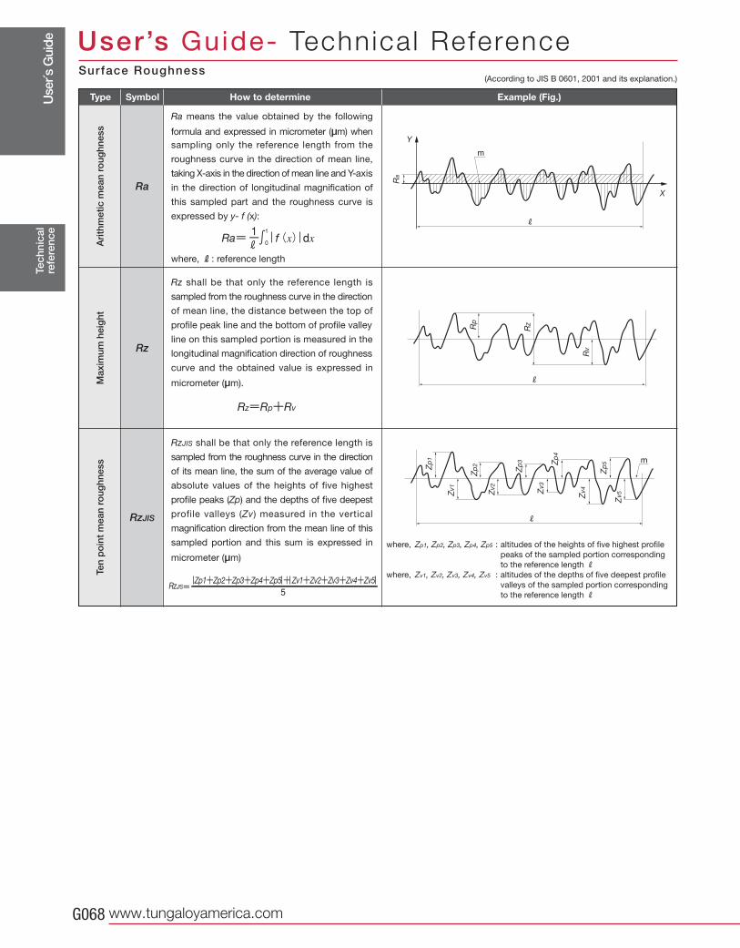
Use
r´s G
uide
www.tungaloyamerica.comG068
RzJIS
Rz
Ra
Tec
hnic
alre
fere
nce
User’s Guide- Technica l Reference(According to JIS B 0601, 2001 and its explanation.)
RzJIS shall be that only the reference length is
sampled from the roughness curve in the direction
of its mean line, the sum of the average value of
absolute values of the heights of five highest
profile peaks (Zp) and the depths of five deepest
profile valleys (Zv) measured in the vertical
magnification direction from the mean line of this
sampled portion and this sum is expressed in
micrometer (μm)
Ra means the value obtained by the following
formula and expressed in micrometer (μm) when
sampling only the reference length from the
roughness curve in the direction of mean line,
taking X-axis in the direction of mean line and Y-axis
in the direction of longitudinal magnification of
this sampled part and the roughness curve is
expressed by y- f (x):
where, R: reference length
Rz shall be that only the reference length is
sampled from the roughness curve in the direction
of mean line, the distance between the top of
profile peak line and the bottom of profile valley
line on this sampled portion is measured in the
longitudinal magnification direction of roughness
curve and the obtained value is expressed in
micrometer (μm).
Type Symbol How to determine Example (Fig.)A
rith
met
ic m
ean
roug
hnes
sM
axim
um h
eig
htTe
n p
oin
t m
ean
roug
hnes
s
where, Zp1, Zp2, Zp3, Zp4, Zp5 : altitudes of the heights of five highest profile
peaks of the sampled portion corresponding
to the reference length Rwhere, Zv1, Zv2, Zv3, Zv4, Zv5 : altitudes of the depths of five deepest profile
valleys of the sampled portion corresponding
to the reference length R
Surface Roughness
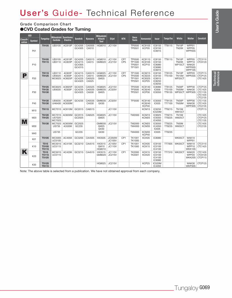
Use
r´s G
uide
Tungaloy G069
P01
T9105 UE6105 AC810P GC4205 GC4305
CA5505 CA510
HG8010 JC110V TP0500 TP0501
KC9105 KCP05
IC8150 IC9150 IC9015
TT8115 TN10P TN20K
WPP01 WPP05
WPP05S
P10
T9105 T9115
UE6105 UE6110
AC810P AC820P
GC4205 GC4215 GC4305 GC4315
CA5515 CA515
HG8010 GM8020
JC110V JC215V
CP7 CP5
TP0500 TP1500 TP0501 TP1501
KC9110 KC9105 KCP10
IC8150 IC9150 IC8080 IC9080 IC9015
TT8115 TN10P TN20K
WP15CT
WPP05 WPP10 WAK20
WPP05S WPP10S
CTC3110 CTCK120
P20
T9115 T9125
UE6110 UE6020 MC6025
AC820P AC830P AC8025P
GC4215 GC4315 GC4225 GC4325
CA5515 CA515
CA5525 CA525
HG8025 GM8020
GM25
JC110V JC215V
CP7 CP5
TP1500 TP2500 TP1501 TP2501
KC9215 KC9225 KC9325 KCP25
IC8150 IC9150 IC9015 IC8250 IC9250
TT8125 TT5100
TN10P TN15M
WP25CT
WPP20 WPP20S
CTCP115 CTCP125 CTC1425
P30
T9125 T9135 T6130
MC6025 UE6035
AC8025P AC830P
GC4225 GC4235 GC4325
CA5525 CA5535 CA530
HG8025 GM8035
GM25
JC215V JC325V
TP2500 TP3500 TP2501
KC9140 KC9240 KCP30
IC8080 IC656
IC9350
TT8125 TT5100 TT8135
TN30P TN30M
WP35CT
WPP30 WAK30
WPP30S
CTCP125 CTC1425 CTC1135 CTC1435 CTC2135
P40T9135 T6130
UE6035 UH6400
AC830P AC630M
GC4235 CA5535 CA530
GM8035 GX30
JC325V TP3500 KC9140 KC9240 KCP40
IC9350 IC635
TT8135 TT7100
TN30P TN30M
WPP30 WAK30
WPP30S
CTC1135 CTC1435 CTC2135
M10T9115 MC7015 AC610M GC2015 CA6515 JC110V KCM15 IC9250
IC520MTT9215 TN15M
WM15CTCTCP115
M20T6120 T9125
MC7015 US7020 MC7025
AC6030M GC2015 GC2025
CA6525 HG8025 GM25
JC110V TM2000 KCM15 KCM25
IC9025 IC9350 IC4050
TT9215 TT9225
TN15M WM25CT
CTC1425 CTCP125 CTC1135
M30T6130 MC7025
US735AC6030M AC630M
GC2025 GC235
GM8035 GM25 GX30
JC215V TM2000 TM4000
KCM25 KCM35
IC9350 IC4050 IC635
TT9225 TT9235
TN30M WM35CT
CTC1435 CTC2135
M40US735 GC235 GX30 TM4000 KCM35
KCP40IC635 TT9235
K01T5105 MC5005
UC5105AC405K GC3205 CA4505 HX3505 JC050W
JC105VCP1 TK1001
TK1000KCK05 IC8080 WK05CT WAK10
WPP01
K10T515T5105 T5115
MC5015 UC5115
AC415K GC3210 CA4515 HX3515 GM10
HG8010
JC105V JC110V
CP1 TK1001 TK1000
KCK05 KCK15
IC9150 IC5100 IC4100
TT7005 WK05CT WAK10 WPP10
WKK10S
CTC3110 CTC1425
K20
T515 T5115 T5125
MC5015 UC5115
AC420K GC3215 CA4515 HX3515 GM8020
JC110V JC215V
CP1 TK2000 TK2001
KCK15 KCK20
IC9150 IC5100 IC4100 IC9080
TT7310 WK20CT WAK20 WPP20
WKK20S
CTC1435 CTCK120 CTCP115
K30T5125 T9115
HG8025 JC215V KCP25 IC520M IC4050
WAK30 WKP30S
CTCP125
Tec
hnic
alre
fere
nce
User’s Guide- Technica l Reference
ISO
Classifi-cation Symbol
Tungaloy MitsubishiCarbide
SumitomoElectric Kyocera Dijet NTK
MitsubishiHitachi
ToolSandvik KennametalSeco
Tools Iscar TaeguTec Widia Walter Ceratizit
Note: The above table is selected from a publication. We have not obtained approval from each company.
�CVD Coated Grades for TurningGrade Comparison Chart
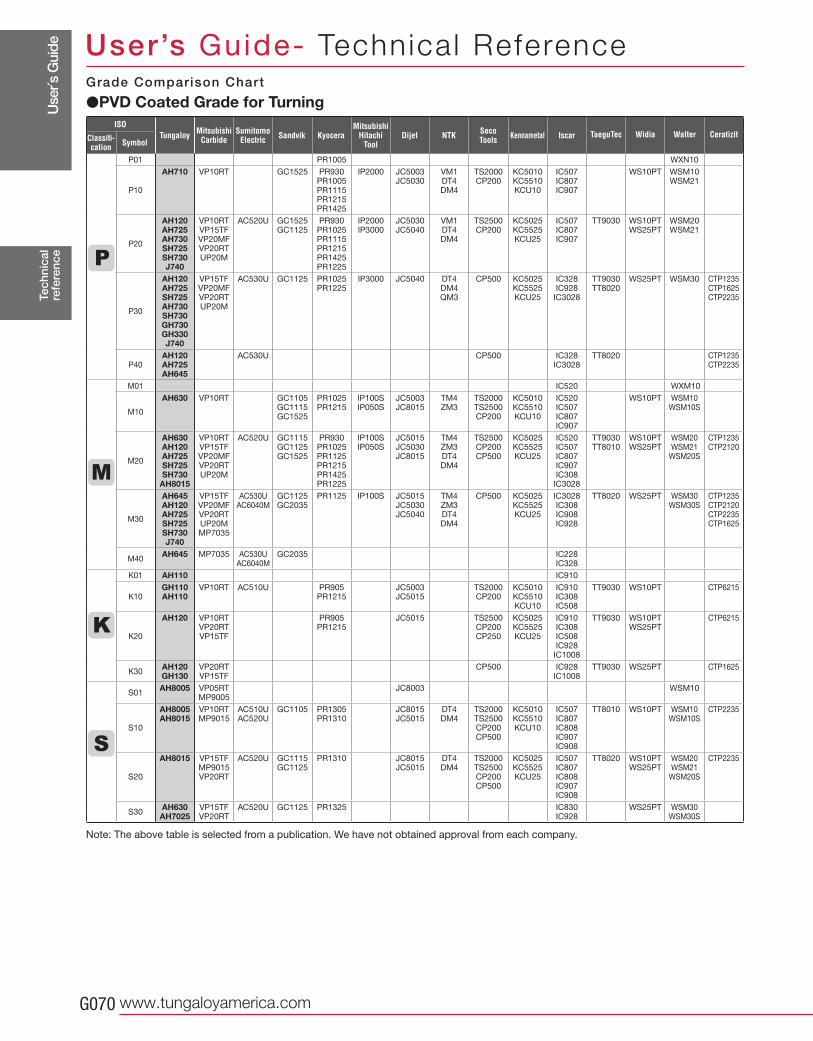
Use
r´s G
uide
www.tungaloyamerica.comG070
P01 PR1005 WXN10
P10
AH710 VP10RT GC1525 PR930 PR1005 PR1115 PR1215 PR1425
IP2000 JC5003 JC5030
VM1 DT4 DM4
TS2000 CP200
KC5010 KC5510 KCU10
IC507 IC807 IC907
WS10PT WSM10 WSM21
P20
AH120 AH725 AH730 SH725 SH730 J740
VP10RT VP15TF VP20MF VP20RT UP20M
AC520U GC1525 GC1125
PR930 PR1025 PR1115 PR1215 PR1425 PR1225
IP2000 IP3000
JC5030 JC5040
VM1 DT4 DM4
TS2500 CP200
KC5025 KC5525 KCU25
IC507 IC807 IC907
TT9030 WS10PT WS25PT
WSM20 WSM21
P30
AH120 AH725 SH725 AH730 SH730 GH730 GH330 J740
VP15TF VP20MF VP20RT UP20M
AC530U GC1125 PR1025 PR1225
IP3000 JC5040 DT4 DM4 QM3
CP500 KC5025 KC5525 KCU25
IC328 IC928
IC3028
TT9030 TT8020
WS25PT WSM30 CTP1235 CTP1625 CTP2235
P40AH120 AH725 AH645
AC530U CP500 IC328 IC3028
TT8020 CTP1235 CTP2235
M01 IC520 WXM10
M10
AH630 VP10RT GC1105 GC1115 GC1525
PR1025 PR1215
IP100S IP050S
JC5003 JC8015
TM4 ZM3
TS2000 TS2500 CP200
KC5010 KC5510 KCU10
IC520 IC507 IC807 IC907
WS10PT WSM10 WSM10S
M20
AH630 AH120 AH725 SH725 SH730
AH8015
VP10RT VP15TF VP20MF VP20RT UP20M
AC520U GC1115 GC1125 GC1525
PR930 PR1025 PR1125 PR1215 PR1425 PR1225
IP100S IP050S
JC5015 JC5030 JC8015
TM4 ZM3 DT4 DM4
TS2500 CP200 CP500
KC5025 KC5525 KCU25
IC520 IC507 IC807 IC907 IC308 IC3028
TT9030 TT8010
WS10PT WS25PT
WSM20 WSM21
WSM20S
CTP1235 CTP2120
M30
AH645 AH120 AH725 SH725 SH730 J740
VP15TF VP20MF VP20RT UP20M MP7035
AC530U AC6040M
GC1125 GC2035
PR1125 IP100S JC5015 JC5030 JC5040
TM4 ZM3 DT4 DM4
CP500 KC5025 KC5525 KCU25
IC3028 IC308 IC908 IC928
TT8020 WS25PT WSM30 WSM30S
CTP1235 CTP2120 CTP2235 CTP1625
M40AH645 MP7035 AC530U
AC6040MGC2035 IC228
IC328
K01 AH110 IC910
K10GH110 AH110
VP10RT AC510U PR905 PR1215
JC5003 JC5015
TS2000 CP200
KC5010 KC5510 KCU10
IC910 IC308 IC508
TT9030 WS10PT CTP6215
K20
AH120 VP10RT VP20RT VP15TF
PR905 PR1215
JC5015 TS2500 CP200 CP250
KC5025 KC5525 KCU25
IC910 IC308 IC508 IC928
IC1008
TT9030 WS10PT WS25PT
CTP6215
K30AH120 GH130
VP20RT VP15TF
CP500 IC928 IC1008
TT9030 WS25PT CTP1625
S01AH8005 VP05RT
MP9005JC8003 WSM10
S10
AH8005 AH8015
VP10RT MP9015
AC510U AC520U
GC1105 PR1305 PR1310
JC8015 JC5015
DT4 DM4
TS2000 TS2500 CP200 CP500
KC5010 KC5510 KCU10
IC507 IC807 IC808 IC907 IC908
TT8010 WS10PT WSM10 WSM10S
CTP2235
S20
AH8015 VP15TF MP9015 VP20RT
AC520U GC1115 GC1125
PR1310 JC8015 JC5015
DT4 DM4
TS2000 TS2500 CP200 CP500
KC5025 KC5525 KCU25
IC507 IC807 IC808 IC907 IC908
TT8020 WS10PT WS25PT
WSM20 WSM21
WSM20S
CTP2235
S30AH630 AH7025
VP15TF VP20RT
AC520U GC1125 PR1325 IC830 IC928
WS25PT WSM30 WSM30S
Tec
hnic
alre
fere
nce
User’s Guide- Technica l Reference
�PVD Coated Grade for TurningGrade Comparison Chart
Note: The above table is selected from a publication. We have not obtained approval from each company.
ISO
Classifi-cation Symbol
Tungaloy MitsubishiCarbide
SumitomoElectric Kyocera Dijet NTK
MitsubishiHitachi
ToolSandvik KennametalSeco
Tools Iscar TaeguTec Widia Walter Ceratizit
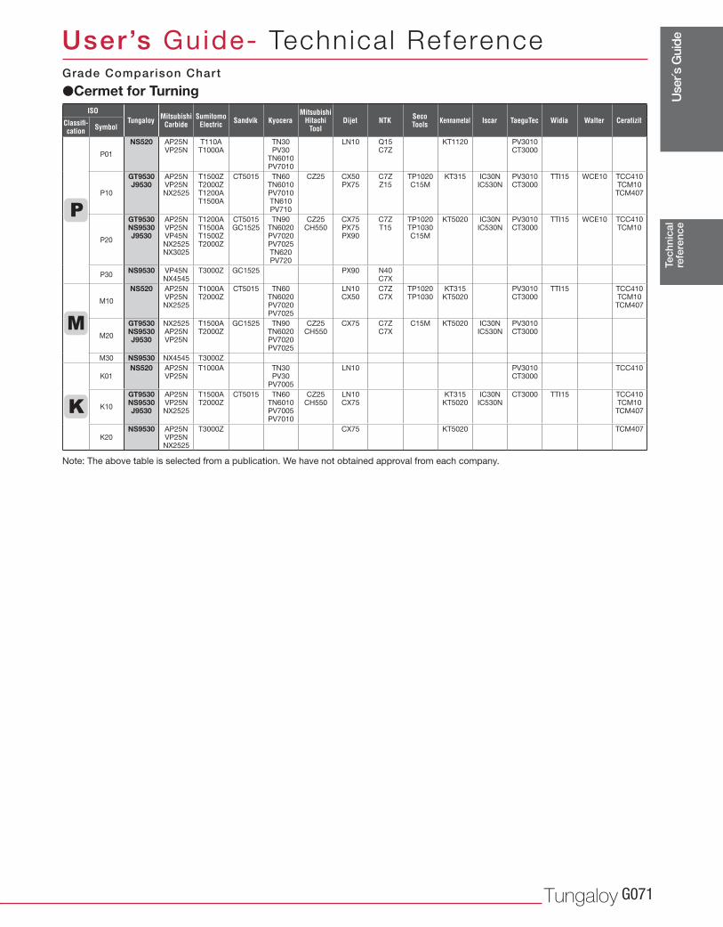
Use
r´s G
uide
Tungaloy G071
P01
NS520 AP25NVP25N
T110AT1000A
TN30PV30
TN6010PV7010
LN10 Q15C7Z
KT1120 PV3010CT3000
P10
GT9530 J9530
AP25NVP25NNX2525
T1500Z T2000ZT1200AT1500A
CT5015 TN60TN6010PV7010 TN610 PV710
CZ25 CX50PX75
C7ZZ15
TP1020C15M
KT315 IC30N IC530N
PV3010CT3000
TTI15 WCE10 TCC410TCM10
TCM407
P20
GT9530 NS9530 J9530
AP25NVP25NVP45NNX2525NX3025
T1200AT1500AT1500ZT2000Z
CT5015 GC1525
TN90TN6020PV7020PV7025 TN620 PV720
CZ25 CH550
CX75PX75PX90
C7ZT15
TP1020TP1030C15M
KT5020 IC30NIC530N
PV3010CT3000
TTI15 WCE10 TCC410TCM10
P30NS9530 VP45N
NX4545T3000Z GC1525 PX90 N40
C7X
M10
NS520 AP25NVP25NNX2525
T1000A T2000Z
CT5015 TN60TN6020PV7020 PV7025
LN10CX50
C7Z C7X
TP1020TP1030
KT315KT5020
PV3010CT3000
TTI15 TCC410TCM10TCM407
M20
GT9530 NS9530 J9530
NX2525AP25NVP25N
T1500A T2000Z
GC1525 TN90TN6020PV7020 PV7025
CZ25 CH550
CX75 C7Z C7X
C15M KT5020 IC30N IC530N
PV3010CT3000
M30 NS9530 NX4545 T3000Z
K01NS520 AP25N
VP25NT1000A TN30
PV30PV7005
LN10 PV3010CT3000
TCC410
K10
GT9530 NS9530 J9530
AP25NVP25NNX2525
T1500A T2000Z
CT5015 TN60TN6010PV7005PV7010
CZ25 CH550
LN10 CX75
KT315 KT5020
IC30N IC530N
CT3000 TTI15 TCC410TCM10
TCM407
K20NS9530 AP25N
VP25NNX2525
T3000Z CX75 KT5020 TCM407
Tec
hnic
alre
fere
nce
User’s Guide- Technica l Reference
NTK
�Cermet for TurningGrade Comparison Chart
ISO
Classifi-cation Symbol
Tungaloy MitsubishiCarbide
SumitomoElectric Kyocera Dijet
MitsubishiHitachi
ToolSandvik KennametalSeco
Tools Iscar TaeguTec Widia Walter Ceratizit
Note: The above table is selected from a publication. We have not obtained approval from each company.
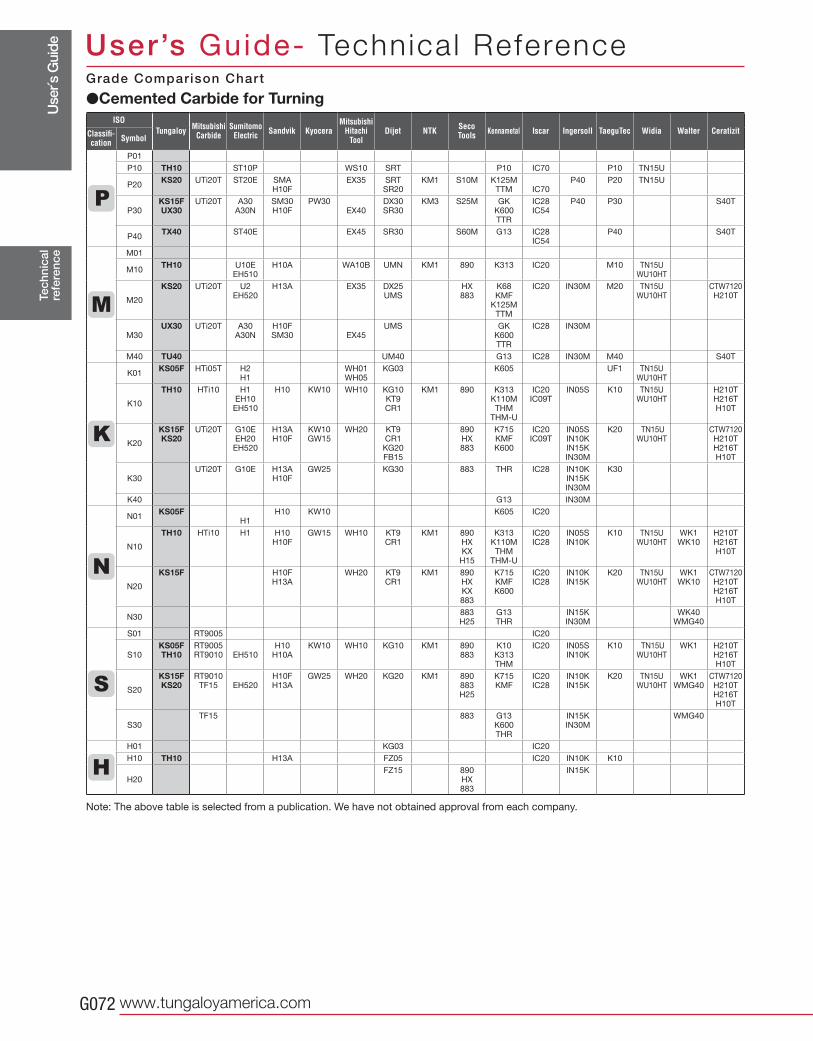
Use
r´s G
uide
www.tungaloyamerica.comG072
P01 P10 TH10 ST10P WS10 SRT P10 IC70 P10 TN15U
P20KS20 UTi20T ST20E SMA
H10FEX35 SRT
SR20KM1 S10M K125M
TTM
IC70P40 P20 TN15U
P30KS15F UX30
UTi20T A30 A30N
SM30 H10F
PW30 EX40
DX30 SR30
KM3 S25M GK K600 TTR
IC28 IC54
P40 P30 S40T
P40TX40 ST40E EX45 SR30 S60M G13 IC28
IC54P40 S40T
M01
M10TH10 U10E
EH510H10A WA10B UMN KM1 890 K313 IC20 M10 TN15U
WU10HT
M20
KS20 UTi20T U2 EH520
H13A EX35 DX25 UMS
HX 883
K68 KMF
K125M TTM
IC20 IN30M M20 TN15U WU10HT
CTW7120 H210T
M30UX30 UTi20T A30
A30NH10F SM30
EX45
UMS GK K600 TTR
IC28 IN30M
M40 TU40 UM40 G13 IC28 IN30M M40 S40T
K01KS05F HTi05T H2
H1WH01 WH05
KG03 K605 UF1 TN15U WU10HT
K10
TH10 HTi10 H1 EH10 EH510
H10 KW10 WH10 KG10 KT9 CR1
KM1 890 K313 K110M THM
THM-U
IC20 IC09T
IN05S K10 TN15U WU10HT
H210T H216T H10T
K20
KS15F KS20
UTi20T G10E EH20
EH520
H13A H10F
KW10 GW15
WH20 KT9 CR1 KG20 FB15
890 HX 883
K715 KMF K600
IC20 IC09T
IN05S IN10K IN15K IN30M
K20 TN15U WU10HT
CTW7120 H210T H216T H10T
K30UTi20T G10E H13A
H10FGW25 KG30 883 THR IC28 IN10K
IN15K IN30M
K30
K40 G13 IN30M
N01KS05F
H1H10 KW10 K605 IC20
N10
TH10 HTi10 H1 H10 H10F
GW15 WH10 KT9 CR1
KM1 890 HX KX H15
K313 K110M THM
THM-U
IC20 IC28
IN05S IN10K
K10 TN15U WU10HT
WK1 WK10
H210T H216T H10T
N20
KS15F H10F H13A
WH20 KT9 CR1
KM1 890 HX KX 883
K715 KMF K600
IC20 IC28
IN10K IN15K
K20 TN15U WU10HT
WK1 WK10
CTW7120 H210T H216T H10T
N30883 H25
G13 THR
IN15K IN30M
WK40 WMG40
S01 RT9005 IC20
S10KS05F TH10
RT9005 RT9010
EH510
H10 H10A
KW10 WH10 KG10 KM1 890 883
K10 K313 THM
IC20 IN05S IN10K
K10 TN15U WU10HT
WK1 H210T H216T H10T
S20
KS15F KS20
RT9010 TF15
EH520
H10F H13A
GW25 WH20 KG20 KM1 890 883 H25
K715 KMF
IC20 IC28
IN10K IN15K
K20 TN15U WU10HT
WK1 WMG40
CTW7120 H210T H216T H10T
S30TF15 883 G13
K600 THR
IN15K IN30M
WMG40
H01 KG03 IC20
H10 TH10 H13A FZ05 IC20 IN10K K10
H20 FZ15 890
HX 883
IN15K
Tec
hnic
alre
fere
nce
User’s Guide- Technica l Reference
�Cemented Carbide for TurningGrade Comparison Chart
Note: The above table is selected from a publication. We have not obtained approval from each company.
ISO
Classifi-cation Symbol
Tungaloy MitsubishiCarbide
SumitomoElectric Kyocera Dijet
MitsubishiHitachi
ToolSandvik KennametalSeco
Tools Iscar TaeguTec WalterWidia CeratizitNTK Ingersoll
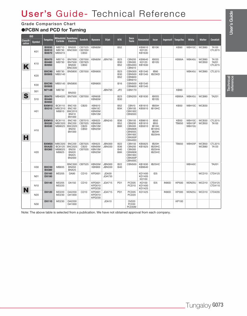
Use
r´s G
uide
Tungaloy G073
K01
BX930 BX910 BX870
MB710 MB730
MB5015
BN500 BNC500
CB7525 CB7050
CB50
KBN60M B52 KB9610 KD120 KB1630
IB10K KB90 WBH10C WCB80 TA100 CTL3215
K10
BX470 BX480 BX950
MB710 MB730
BN7000 BN7500 BN500
BNC500
CB7050 CB7925
CB50
KBN60M JBN795 B23 B30 B52
CBN200 CBN300
CBN400C CBN010
KB9640 KD120 KB1630
IB05S IB10S
KB90A WBK40U WCB80 WCB50
TA120 TA201
CTL3215
K20
BXC90 BX90S
MB730 MBS140
BNS800 CB7050 KBN900 B23 B30 B52
CBN300 CBN500 CBN600 CBN010
KB1340 KB1345
IB90 IB25KD
WBK45U WCB80 CTL3215
K30BXC90 BX90S
MBS140 BNS800 KBN900 B16 CBN500 CBN600
KB1340 KB1345
S01M714B MB730
BN350JBN795 JP2 CBN170 KB90
S10BX470 BX480 BX950
MB4020 BN7500 CB7050 KBN65B KBN65M
B23 B30
CBN200 KB1630 IB05S IB10S
KB90A WBK45U WCB80 TA201
H01
BXM10 BX310
BC8110 MBC010 MB810
BNC100 BNC160 BNC2010
BNX10 BN1000
CB20 KBN510 KBN10C KBN05M KBN10M
B52 B5K
CBN10 CBN100
CBN160C CBN050C
KB1610 KB5610
IB05H IB10HC
KB50 WBH10C WCB30
H10
BXM10 BX330 BX530
BC8110 MBC020 MB8025
BNC160 BNC200 BNC2020
BN250 BN1000
CB7015 CB7025
CB20 CB50
KBN525 KBN05M KBN10M KBN25M
JBN245 B36 B52 B6K
CBN150 CBN200 CBN300
CBN060K CBN050C CBN160C CBN300P CBN400C
KB9610 KB1610 KB5610
IB50 IB55
IB10H IB10HC IB20H
IB25HA
KB50 TB650
WBH10C WBH10P WBH10U
WCB30 WCB50
CTL3215 TA100
H20
BXM20 BXA20 BX360
MBC020 BC8120 MB8025 MB825
BNC200 BNC2020
BN250 BNX20 BNX25 BN2000
CB7025 CB20
CB7035
KBN525 KBN05M KBN10M KBN25M
JBN300 JBN330
B22 B36 B40 B6K
CBN150 CBN200 CBN300
CBN060K CBN160C CBN300P CBN400C
KB5625 KB1625
IB20H IB20HC IB25HA IB25HC
TB650 WBH25P WCB50 WCB80
CTL3215 TA120
H30
BXC50 BX380
MB835
BNC300 BN350 BNX25
CB7525 KBN35M KBN900
JBN300 JBN330
B22 B40
CBN500 KB1630 KB9640
IB25HC WBH40C TA201
N01DX160 DX180
MD205 DA90 CD10 KPD001 JDA30 JDA735
KD1400 KD1405 KD100
ID5 WCD10 CTD4125
N10DX140 MD205
MD220DA150 CD10 KPD001
KPD010 KPD230
JDA715 PD1 PCD05 PCD10
KD100 KD1400 KD1425
ID5 IN90D KP500 WDN25U WCD10 CTD4125 CTD4110
N20DX120 MD220
MD230DA2200 DA1000
CD10 KPD001 KPD010 KPD230
JDA715 PD1 PCD05 PCD20
KD1425 IN90D KP300 WDN25U WCD10 CTD4205
N30DX110 MD230 DA2200
DA1000JDA10 OVD20
PCD30 PCD30M
KP100
Tec
hnic
alre
fere
nce
User’s Guide- Technica l Reference
NTKISO
Classifi-cation Symbol
Tungaloy MitsubishiCarbide
SumitomoElectric Kyocera DijetSandvik KennametalSeco
Tools Iscar TaeguTecIngersoll Widia Walter Ceratizit
�PCBN and PCD for TurningGrade Comparison Chart
Note: The above table is selected from a publication. We have not obtained approval from each company.
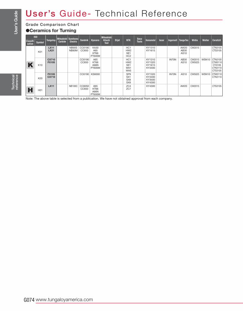
Use
r´s G
uide
www.tungaloyamerica.comG074
K01
LX11 LX21
NB90S NB90M
CC6190 CC650
KA30 A65
KT66 PT600M
HC1 HW2 SE1 HC2
KY1310 KY1615
AW20 AB30 AS10
CW2015 CTN3105 CTS3105
K10
CX710 FX105
CC6190 CC650
A65 KT66 A66N
PT600M
HC1 HW2 SE1 WA1 WA5
KY1310 KY1320 KY1615 KY3400
IN70N AB30 AS10
CW2015 CW5025
WSN10 CTN3105 CTM3110 CTI3105 CTN3110 CTS3105
K20
FX105 CX710
CC6190 KS6000 SP9 SX1 SX8 SX9
KY1320 KY3400 KY3500 KY4300
IN70N AS10 CW5025 WSN10 CTM3110 CTN3110
H01
LX11 NB100C CC6050 CC650
A65 KT66 A66N
PT600M
ZC4 ZC7
KY4300 AW20 CW2015 CTS3105
Tec
hnic
alre
fere
nce
User’s Guide- Technica l Reference
ISO
Classifi-cation Symbol
Tungaloy MitsubishiCarbide
SumitomoElectric Kyocera Dijet
MitsubishiHitachi
ToolSandvik KennametalSeco
Tools Iscar TaeguTec WalterWidia CeratizitNTK Ingersoll
�Ceramics for TurningGrade Comparison Chart
Note: The above table is selected from a publication. We have not obtained approval from each company.
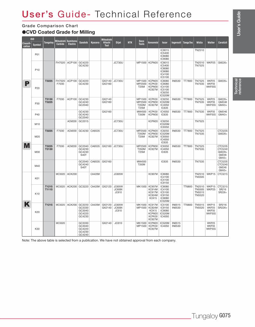
Use
r´s G
uide
Tungaloy G075
P01
IC9015 IC5400 IC8080 IC9080
TN2510
P10
FH7020 ACP100 GC4220 GC4230
JC730U MP1500 KCPM20 IC9015 IC5400 IC8080 IC9080 IC4100 IC5100
TN2510 TN7525
WKP25 GM226+
P20
T3225 FH7020 F7030
ACP100 GC4220 GC4230
GX2140 GX2160
JC730U MP1500 MP2500
T25M
KCPM20 KCPK30 KCPM30 KC927M
IC8080 IC9080 IC4100 IC5100 IC9250 IC520M
IN6530 TT7800 TN7525 TN7535
WKP25 WKP35
WKP35S
GM226+
P30
T3130 T3225
F7030 ACP100 GC4230 GC4240 GC2040
GX2140 GX2160
MP1500 MP2500 T350M T25M
KCPK30 KCPM30 KC927M
IC9250 IC520M IC4050 IC635
IN6530 TT7800 TN7525 TN7535
WKP25 WKP35
WKP35S
GM226+ GM246 GM43+
P40GC4230 GC4240 GC2040
GX2160 MM4500 T350M
KCPK30 KCPM30
IC4050 IC635
IN6530 TT7800 TN7535 WKP35 WKP35S
GM246 GM43+
M10ACM200 GC2015 JC730U KCPM20 IC9250
IC520M IC9350
TN7525
M20
T3225 F7030 ACM200 GC4230 CA6535 JC730U MP2500 T350M T25M
KCPM20 KCPM30 KC927M
IC9250 IC520M IC9350 IC4050 IC635
IN6530 TT7800 TN7525 TN7535
CTC5235 GM226+
M30
T3225 T3130
F7030 ACM200 GC2040 GC4230 GC4240
S40T
CA6535 GX2160 JC730U MP2500 T350M T25M
KCPM30 KC927M
IC9350 IC4050 IC635
IN6530 TT7800 TN7525 TN7535
CTC5235 CTC5240 GM226+ GM246 GM43+
M40
GC2040 GC4240
S40T
CA6535 GX2160 MM4500 T350M
IC635 IN6530 TN7535 CTC5235 CTC5240 GM246 GM43+
K01
MC5020 ACK200 CA420M JC605W KC907M IC8080 IC4100 IC5100 IC9150
TN2510 TN5505
WKP15 CTC3215
K10
T1215 T1115
MC5020 ACK200 GC3220 CA420M GX2120 JC605W JC608X JC610
MK1500 KC907M KC914M KC917M KC924M KCK15
IC8080 IC4100 IC5100 IC9150 IC9080 IC520M
TT6800 TN2510 TN5505 TN5515 TN5520
WKP15 WKP25
CTC3215 SR216
SR226+
K20
T1215 MC5020 ACK200 GC3220 GC3330 GC3040 GC4220 GC4230
CA420M GX2120 GX2140
JC605W JC608X JC610
MK1500 MP1500
KC917M KC924M KCK15
KCPM20 KCPK30 KC927M
IC5100 IC9150 IC9080 IC520M IC4050
IN6515 IN6530
TT6800 TN5515 TN5520
WKP15 WKP25 WKP35
WKP35S
SR216 SR226+
K30
MC5020 GC3330 GC3040 GC4220 GC4230 GC4240
GX2140 JC610 MK1500 MP1500
KCPM20 KCPK30 KC927M
IC520M IC4050
IN6515 IN6530
WKP25 WKP35
WKP35S
Tec
hnic
alre
fere
nce
User’s Guide- Technica l Reference
�CVD Coated Grade for MillingGrade Comparison Chart
Note: The above table is selected from a publication. We have not obtained approval from each company.
ISO
Classifi-cation Symbol
Tungaloy MitsubishiCarbide
SumitomoElectric Kyocera Dijet
MitsubishiHitachi
ToolSandvik KennametalSeco
Tools IscarNTK TaeguTec WalterWidiaIngersoll Ceratizit
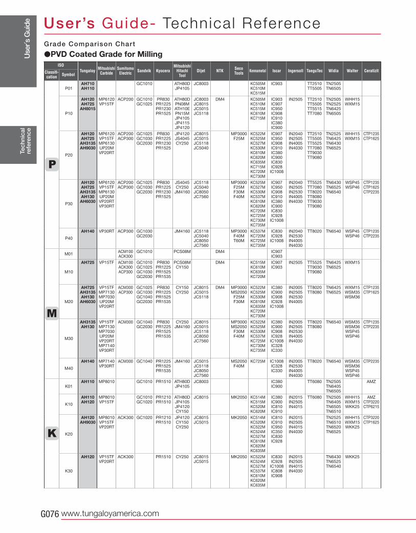
Use
r´s G
uide
www.tungaloyamerica.comG076
P01AH710 AH110
GC1010 ATH80D JP4105
JC8003 KC505M KC510M KC515M
IC903 TT2510 TT5505
TN2505 TN6505
P10
AH120 AH725
AH8015
MP6120 VP15TF
ACP200 GC1010 GC1025
PR830 PR1225 PR1230 PR1525
ATH80D PN08M ATH10E PN15M JP4105 JP4115 JP4120
JC8003 JC8015 JC5015 JC5118
DM4 KC505M KC510M KC515M KC610M KC715M
IC903 IC907 IC950 IC908 IC910 IC380 IC900
IN2505 TT2510 TT5505 TT5515 TT7080
TN2505 TN2525 TN6425 TN6505
WHH15 WXM15
P20
AH120 AH725
AH3135 AH9030
MP6120 VP15TF MP6130 UP20M VP20RT
ACP200 ACP300
GC1025 GC1030 GC2030
PR830 PR1225 PR1230 PR1525
JP4120 JS4045 CY250
JC8015 JC5015 JC5118 JC5040
MP3000 F25M
KC522M KC525M KC527M KC530M KC610M KC620M KC635M KC715M KC720M KC730M
IC907 IC950 IC908 IC910 IC380 IC900 IC830 IC928
IC1008
IN2040 IN2505 IN4005 IN4030
TT2510 TT5505 TT5525 TT7080 TT9030 TT9080
TN2525 TN6425 TN6430 TN6525
WHH15 WXM15
CTP1235 CTP1625
P30
AH120 AH725
AH3135 AH130
AH6030
MP6120 VP15TF MP6130 UP20M VP20RT VP30RT
ACP200 ACP300
GC1025 GC1030 GC2030
PR830 PR1225 PR1230 PR1525
JS4045 CY250
JM4160
JC5118 JC5040 JC8050 JC7560
MP3000 F25M F30M F40M
KC525M KC527M KC530M KC537M KC610M KC620M KC720M KC725M KC730M KC735M
IC907 IC950 IC908 IC910 IC380 IC900 IC830 IC928
IC1008
IN2040 IN2505 IN2530 IN4005 IN4030
TT5525 TT7080 TT8020 TT8080 TT9030 TT9080
TN6430 TN6525 TN6540
WSP45 WSP46
CTP1235 CTP1625 CTP2235
P40
AH140 VP30RT ACP300 GC1030 GC2030
JM4160 JC5118 JC5040 JC8050 JC7560
MP3000 F40M T60M
KC537M KC720M KC725M KC735M
IC830 IC928
IC1008
IN2040 IN2530 IN4005 IN4030
TT8020 TN6540 WSP45 WSP46
CTP1235 CTP2235
M01ACM100 ACK300
GC1010 PCS08M DM4 IC907 IC903
M10
AH725 VP15TF ACM100 ACK300 ACP300
GC1010 GC1025 GC1030 GC2030
PR830 PR1225 PR1525 PR1535
PCS08M CY150
DM4 KC515M KC610M KC635M KC720M
IC907 IC903
IN2505 TT5525 TT9030 TT9080
TN6425 TN6525
WXM15
M20
AH725 AH3135 AH130 AH6030
VP15TF MP7130 MP7030 UP20M VP20RT
ACM300 ACP300
GC1025 GC1030 GC1040 GC2030
PR830 PR1225 PR1525 PR1535
CY150 CY250
JC8015 JC5015 JC5118
DM4 MP3000 MS2050
F25M F30M
KC522M KC525M KC530M KC610M KC635M KC720M KC730M
IC380 IC900 IC908 IC928
IC1008
IN2005 IN2505 IN2530 IN4005
TT8020 TT8080
TN6425 TN6525
WXM15 WSM35 WSM36
CTP1235 CTP1625
M30
AH3135 AH130
VP15TF MP7130 MP7030 UP20M VP20RT MP7140 VP30RT
ACM300 GC1040 GC2030
PR830 PR1225 PR1525 PR1535
CY250 JM4160
JC8015 JC5015 JC5118 JC8050 JC7560
MP3000 MS2050
F30M F40M
KC522M KC525M KC530M KC537M KC725M KC730M KC735M
IC380 IC900 IC908 IC928
IC1008 IC328 IC330
IN2005 IN2505 IN2530 IN4005 IN4030
TT8020 TT8080
TN6540 WSM35 WSM36 WSP45 WSP46
CTP1235 CTP2235
M40
AH140 MP7140 VP30RT
ACM300 GC1040 PR1225 PR1525 PR1535
JM4160 JC5015 JC5118 JC8050 JC7560
MS2050 F40M
KC725M IC1008 IC328 IC330
IN2005 IN2530 IN4005 IN4030
TT8020 TN6540 WSM35 WSM36 WSP45 WSP46
CTP2235
K01AH110 MP8010 GC1010 PR1510 ATH80D
JP4105 JC8003
IC380 IC900
TT6080 TN2505 TN6405 TN6505
AMZ
K10
AH110 AH120
MP8010 VP15TF
GC1010 GC1020
PR1210 PR1510
ATH80D JP4105 JP4120 CY150
JC8015 MK2050 KC514M KC515M KC520M KC620M
IC380 IC900 IC810 IC910
IN2015 IN2505 IN4015
TT6080 TN2505 TN6405 TN6505 TN6510
WHH15 WXM15 WKK25
AMZ CTP3220 CTP6215
K20
AH120 AH9030
MP8010 VP15TF VP20RT
ACK300 GC1020 PR1210 PR1510
JP4120 CY150 CY250
JC8015 JC5015
MK2050 KC514M KC520M KC522M KC524M KC527M KC610M KC620M KC635M
IC810 IC910 IC950 IC350 IC830 IC928
IN2015 IN2505 IN4015 IN4030
TN2525 TN6510 TN6520 TN6525
WHH15 WXM15 WKK25
CTP3220 CTP1625
K30
AH120 VP15TF VP20RT
ACK300 PR1510 CY250 JC8015 JC5015
MK2050 KC522M KC524M KC527M KC537M KC610M KC620M KC635M
IC830 IC928 IC1008 IC808 IC908
IN2015 IN2505 IN4015 IN4030
TN6430 TN6525 TN6540
WKK25
Tec
hnic
alre
fere
nce
User’s Guide- Technica l Reference
�PVD Coated Grade for MillingGrade Comparison Chart
ISO
Classifi-cation Symbol
Tungaloy MitsubishiCarbide
SumitomoElectric Kyocera Dijet
MitsubishiHitachi
ToolSandvik KennametalSeco
Tools Iscar TaeguTec WalterWidia CeratizitNTK Ingersoll
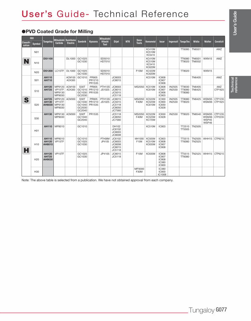
Use
r´s G
uide
Tungaloy G077
N01KC410M KC510M KC5410
TT6080 TN6501 AMZ
N10
DS1100 DL1000 GC1025 GC1030
SD5010 HD7010
KC410M KC510M KC5410 KC620M
TT6080 TT8020
TN6501 TN6502
WXN15 AMZ
N20DS1200 LC15TF DL1000 GC1025
GC1030SD5010 HD7010
F15M KC422M KC620M
TT8020 WXN15
S01AH110 AH710
ACM100 ACK300
GC1010 PR905 PR1210 PR1535
JC8003 JC8015
KC510M IC808 IC907 IC908
TN6405 AMZ
S10
AH120 AH725
MP9120 VP15TF MP9130 MP9030
ACM100 ACK300
S30T GC1010 GC1030 GC2030
PR905 PR1210 PR1535
PTH13S JS1025
JC8003 JC8015 JC5015 JC5118
MS2050 KC510M KC610M
IC808 IC907 IC908 IC903
IN2505 IN2530
TT9030 TT9080 TT8080
TN6405 TN6425
AMZ CTP1625
S20
AH725 AH130
AH6030
MP9120 VP15TF MP9130 MP9030
ACM300 S30T GC1030 GC1040 GC2030 GC2040
PR905 PR1210 PR1535
PTH13S JS1025
JC8015 JC5015 JC5118 JC8050 JC7560
MS2050 F40M
KC522M KC525M KC610M
IC300 IC900 IC830 IC928
IN2505 IN2530
TT8080 TT8020
TN6425 WSM35 WSM36
CTP1235 CTP1625
S30
AH130 MP9130 MP9030
ACM300 S30T GC1040 GC2040
PR1535 JC5118 JC8050 JC7560
MS2050 F40M
KC522M KC525M KC725M
IC830 IC928
IN2530 TT8020 TN6540 WSM35 WSM36 WSP45 WSP46
CTP1235 CTP2235
H01
AH110 MP8010 GC1010 DH102 JC6102 JC8003 JC8008
KC510M IC903 TT2510 TT5505
TN2505
H10
AH110 AH120AH8015
MP8010 VP15TF
GC1010 GC1025 GC1030
PTH08M JP4105
JC6102 JC8003 JC8008 JC8015 JC5118
MH1000 F15M
KC505M KC510M KC635M
IC903 IC808 IC907 IC908
TT5515 TT6080
TN2505 TN2525
WHH15 CTP6215
H20
AH120 AH725
AH9030
VP15TF GC1025 GC1030
JP4105 JC8015 JC5118
F15M KC635M IC808 IC907 IC908 IC380 IC900
TT5515 TT6080
TN2525 WHH15 CTP6215
H30 MP3000
F30MIC380 IC900
IC1008
Tec
hnic
alre
fere
nce
User’s Guide- Technica l Reference
Note: The above table is selected from a publication. We have not obtained approval from each company.
ISO
Classifi-cation Symbol
Tungaloy MitsubishiCarbide
SumitomoElectric Kyocera Dijet
MitsubishiHitachi
ToolSandvik KennametalSeco
Tools Iscar TaeguTec WalterWidia CeratizitNTK Ingersoll
�PVD Coated Grade for Milling
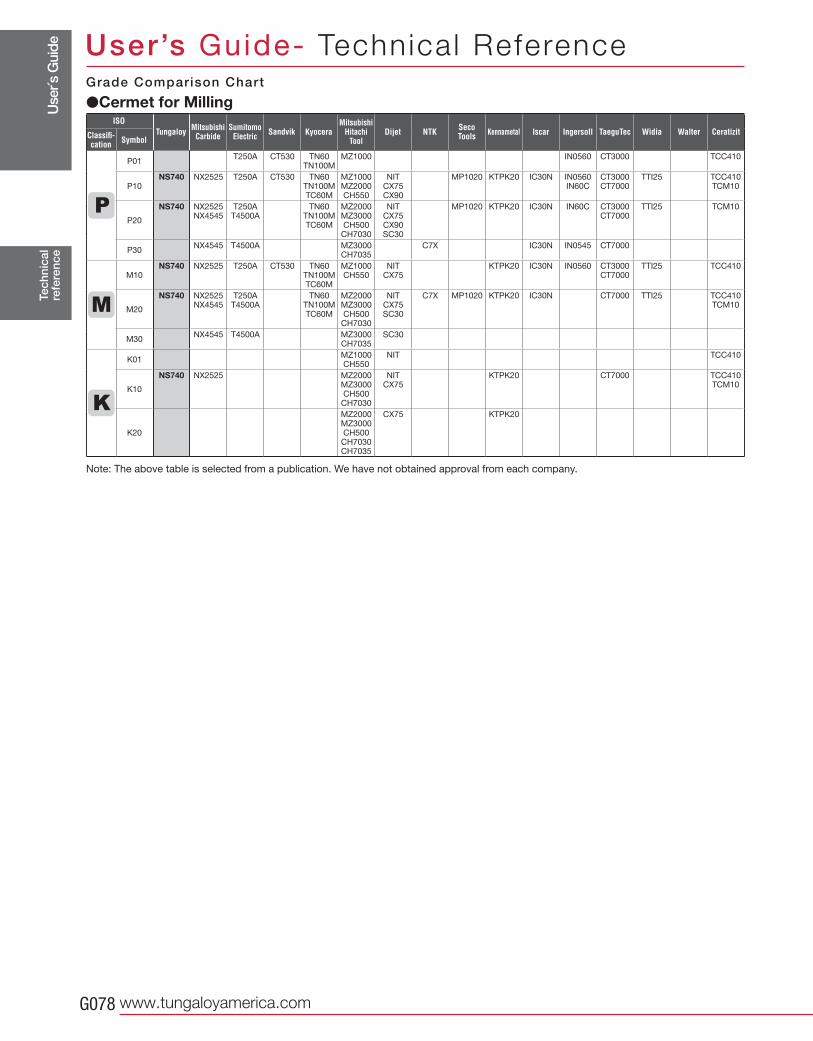
Use
r´s G
uide
www.tungaloyamerica.comG078
P01T250A CT530 TN60
TN100MMZ1000 IN0560 CT3000 TCC410
P10NS740 NX2525 T250A CT530 TN60
TN100MTC60M
MZ1000MZ2000CH550
NITCX75CX90
MP1020 KTPK20 IC30N IN0560IN60C
CT3000CT7000
TTI25 TCC410TCM10
P20
NS740 NX2525NX4545
T250AT4500A
TN60TN100MTC60M
MZ2000MZ3000CH500
CH7030
NITCX75CX90SC30
MP1020 KTPK20 IC30N IN60C CT3000CT7000
TTI25 TCM10
P30NX4545 T4500A MZ3000
CH7035C7X IC30N IN0545 CT7000
M10NS740 NX2525 T250A CT530 TN60
TN100MTC60M
MZ1000CH550
NITCX75
KTPK20 IC30N IN0560 CT3000CT7000
TTI25 TCC410
M20
NS740 NX2525NX4545
T250AT4500A
TN60TN100MTC60M
MZ2000MZ3000CH500
CH7030
NITCX75SC30
C7X MP1020 KTPK20 IC30N CT7000 TTI25 TCC410TCM10
M30NX4545 T4500A MZ3000
CH7035SC30
K01MZ1000CH550
NIT TCC410
K10
NS740 NX2525 MZ2000MZ3000CH500CH7030
NITCX75
KTPK20 CT7000 TCC410TCM10
K20
MZ2000MZ3000CH500
CH7030CH7035
CX75 KTPK20
Tec
hnic
alre
fere
nce
User’s Guide- Technica l ReferenceGrade Comparison Chart
Note: The above table is selected from a publication. We have not obtained approval from each company.
ISO
Classifi-cation Symbol
Tungaloy MitsubishiCarbide
SumitomoElectric Kyocera Dijet
MitsubishiHitachi
ToolSandvik KennametalSeco
Tools Iscar TaeguTec WalterWidia CeratizitNTK Ingersoll
�Cermet for Milling
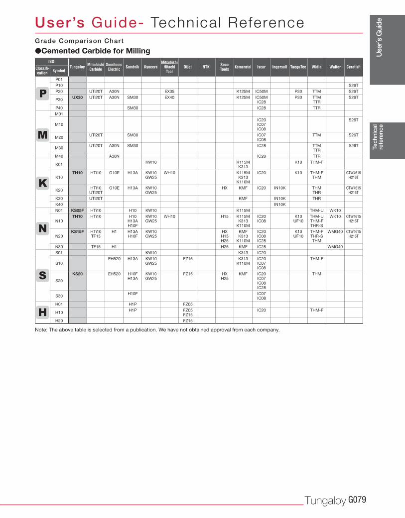
Use
r´s G
uide
Tungaloy G079
P01
P10 S26T
P20 UTi20T A30N EX35 K125M IC50M P30 TTM S26T
P30UX30 UTi20T A30N SM30 EX40 K125M IC50M
IC28P30 TTM
TTRS26T
P40 SM30 IC28 TTR
M01
M10IC20 IC07 IC08
S26T
M20UTi20T SM30 IC07
IC08TTM S26T
M30UTi20T A30N SM30 IC28 TTM
TTRS26T
M40 A30N IC28 TTR
K01KW10 K115M
K313K10 THM-F
K10TH10 HTi10 G10E H13A KW10
GW25WH10 K115M
K313 K110M
IC20 K10 THM-F THM
CTW4615 H216T
K20HTi10
UTi20TG10E H13A KW10
GW25HX KMF IC20 IN10K THM
THRCTW4615
H216T
K30 UTi20T KMF IN10K THR
K40 IN10K
N01 KS05F HTi10 H10 KW10 K115M THM-U WK10
N10TH10 HTi10 H10
H13A H10F
KW10 GW25
WH10 H15 K115M K313
K110M
IC20 IC08
K10 UF10
THM-U THM-F THR-S
WK10 CTW4615 H216T
N20KS15F HTi10
TF15H1 H13A
H10FKW10 GW25
HX H15 H25
KMF K313
K110M
IC20 IC08 IC28
K10 UF10
THM-F THR-S THM
WMG40 CTW4615 H216T
N30 TF15 H1 H25 KMF IC28 WMG40
S01 KW10 K313 IC20
S10EH520 H13A KW10
GW25FZ15 K313
K110MIC20 IC07 IC08
THM-F
S20
KS20 EH520 H10F H13A
KW10 GW25
FZ15 HX H25
KMF IC20 IC07 IC08 IC28
THM
S30H10F IC07
IC08
H01 H1P FZ05
H10H1P FZ05
FZ15IC20 THM-F
H20 FZ15
Tec
hnic
alre
fere
nce
User’s Guide- Technica l Reference
ISO
Classifi-cation Symbol
Tungaloy MitsubishiCarbide
SumitomoElectric Kyocera Dijet
MitsubishiHitachi
ToolSandvik KennametalSeco
Tools Iscar TaeguTec WalterWidia CeratizitNTK Ingersoll
�Cemented Carbide for MillingGrade Comparison Chart
Note: The above table is selected from a publication. We have not obtained approval from each company.
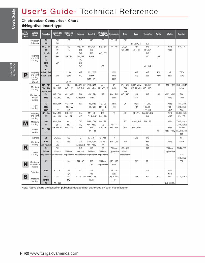
Use
r´s G
uide
www.tungaloyamerica.comG080
Precision finishing
01
TF
PK
FH
FA DP QF FE FS , LF PF
SF , PP , TF FA
Finishing and lightcutting
TS , TSF
ZF
11 , NS
AS
TQ
NM
CB
C
SA
FY
C
SH
MP
SU
FL
SE , SX
PQ , VF
CJ
PQ
GP , PP
HQ
GS
CQ
PF , QF
LC
MF
R/L-K
BE , BH
AB , CT
CE
FF , FN UA , FT
UR , UT
F3P
NF , SF
FG
VF , EA
FC
MC
ML , MP
4
AP
NF3
NS6
CF , TF
Finishing and lightcutting(With
Wiper)
AFW , FW
ASW , SW SW
LUW
SEW
GUW
WP
WQ
WL , WF
WMX
WM , WR
FW
MW
RW
WF
WG
WS
WT
FW
MW
NF
NM
TFQ
TMQ
Medium cutting
TM , AM
DM , ZM
All-round
MA
MH , MP
GU
GE , UX
HS, PT, GT
CS, PS
PM , QM
XM , XRM
AH
AE , AY , B
P
MN
PG , UB
GN
GNP
M3P, M3M
PP, TF, GN
PC , MT
MC , MG-
48 NMT , NM4 TMF , TMM
M50
Medium to heavycutting
TH
THS
RP , GH
HZ , HL
MU , ME
HG
PH
All-round
HM , PR
MR
RE RN , RP
MR
GG , UD NR
MR
RT 49 NM5 , NM6
NM9
TM
TRM
Heavy cutting
TU
TRS
TUS
HM , HX
HV
HG , HP
HU , HW
HF
PX PR , MR
HR , QR
TE , UE
HX , HE
H
RM
RH
UC R3P
NM
HT , HD
RX , RH
HY , HZ
NR6
NRF
NRR
TRR , TR
R28 , R58
R88
Finishing and lightcutting
SF , SA
SS
GM , MS
SH , LM
EX , EG
SU , EF
GU
MQ
MF , XF
LC , R/L-K
MP
BH , AB
FP SF TF , VL EA , SF , SU
FG
NF4
NMS
CF, F30, M34
F32, TF
Medium cutting
SM
S
MM , MA
ES
GU
HM
TK
MU
MM , QM
XM , XRM
PV , SE
DE MP , P
SZ M3M , PP EM , ET NM4 TMF , M42
M30 , M52
Heavy cutting
TH , SH
TU
GH, RM, HZ EM , MU MS MR
HM , PR
AH , AE UP , RP SG MR , MH
SR
NR4
NRT , NRS
TM, M60
TRM, TMR, TRR
R80
Finishing CF LK, MA UZ C KF , XF Y , AH FN GN FG CF
Medium cutting
CM
All-round
MK
GK
GZ ZS
All-round
KM , QM
XM , XRM
V, AE
VA
RP , UN PG MT
MG
NM5 M50
Heavy cutting
CH
Without
chipbreaker
RK
Without
chipbreaker
Without
chipbreaker
GC
Without
chipbreaker
KR
Without
chipbreaker
RE
Without
chipbreaker
Without
chipbreaker
GG , UD
Without
chipbreaker
RT Without
chipbreaker
TMR , TR
R28
R58 , R88
Cutting of non-ferrous
metals
P AX AH , A3 MF
QM
Without
chipbreaker
MS , MP
MG
PP ML F32
FinishingHRF FJ , LS EF
EX
MQ SF
01
FS , LS
MS
SF NFT
NF4
Medium cutting
HRM
HMM
SA
MS
RS , GJ
EG
MU
TK, MS, MU MM , QM
SMR
UP, P, NGP
RP
PP SU SM NMS
NM4, NRS, NR4
M34 , M52
Tec
hnic
alre
fere
nce
User’s Guide- Technica l Reference
�Negative insert typeChipbreaker Comparison Chart
Note: Above charts are based on published data and not authorized by each manufacturer.
ISOClassifi-cation
CuttingMode Tungaloy Mitsubishi
CarbideSumitomo
Electric Kyocera Sandvik MitsubishiHitachi Tool Kennametal Dijet Iscar TaeguTec Widia Walter Ceratizit
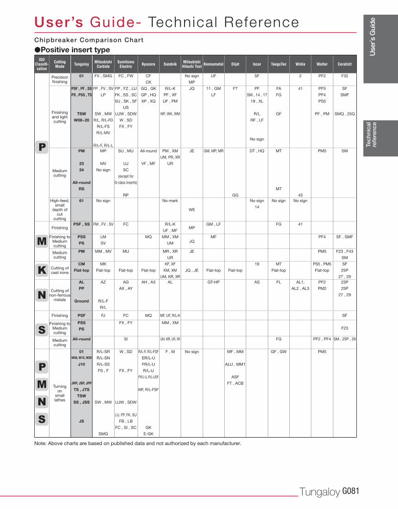
Use
r´s G
uide
Tungaloy G081
Precision finishing
01 FV , SMG FC , FW CF
CK
No sign
MP
UF SF 2 PF2 F32
Finishing and lightcutting
PSF , PF , SS
PS , PSS , TS
TSW
W08~20
FP , FV , SV
LP
SW , MW
R/L, R/L-FD
R/L-FS
R/L-MV
R/L-F, R/L-L
FP , FZ , LU
FK , SS , SC
SU , SK , SF
US
LUW , SDW
W , SD
FX , FY
GQ , GK
GP , HQ
XP , XQ
R/L-K
PF , XF
UF , PM
WF, WK, WM
JQ 11 , GM
LF
FT PF
SM , 14 , 17
19 , XL
R/L
RF , LF
No sign
FA
FG
GF
41 PF5
PF4
PS5
PF , PM
SF
SMF
SMQ , 25Q
Medium cutting
PM
23
24
All-round
RS
MP
MV
No sign
SU , MU
UJ
SC
(except for
G-class inserts)
RP
All-round
VF , MF
PM , XM
UM, PR, XR
UR
JE GM, MP, MR
GG
DT , HQ MT
MT
43
PM5 SM
High-feed, small
depth of cut
cutting
61 No sign No mark
WE
No sign
14
No sign No sign
FinishingPSF , SS FM , FV , SV FC R/L-K
UF , MFMP
GM , LF FG 41
Finishing to Mediumcutting
PSS
PS
LM
SV
MQ MM , XM
UM JQMF PF4 SF , SMF
Medium cutting
PM MM , MV MU MR , XR
UR
JE PM5 F23 , F43
SM
Cutting of cast irons
CM
Flat-top
MK
Flat-top Flat-top Flat-top
KF, XF
KM, XM
UM, KR, XR
JQ , JE Flat-top Flat-top
19 MT
Flat-top
PS5 , PM5
Flat-top
SF
25P
27 , 29
Cutting of non-ferrous
metals
AL
PP
Ground
AZ
R/L-F
R/L
AG
AX , AY
AH , A3 AL GT-HP AS FL AL1,
AL2 , AL3
PF2
PM2
23P
25P
27 , 29
Finishing PSF FJ FC MQ MF, UF, R/L-K SF
Finishing to Mediumcutting
PSS
PS
FX , FY MM , XM
F23
Medium cutting
All-round SI UM, MR, UR, XR FG PF2 , PF4 SM , 25P , 29
Turning on
small lathes
01 W08, W15, W20
J10
JRP, JSP, JPP
TS , JTS
TSW
SS , JSS
JS
R/L-SR
R/L-SN
R/L-SS
FS , F
SW , MW
SMG
W , SD
FX , FY
LUW , SDW
LU, FP, FK, SU
FB , LB
FC , SI , SC
R/L-F, R/L-FSF
ER/L-U
FR/L-U
R/L-U
FR/L-U, R/L-USF
MF, R/L-FSF
GK
E-GK
F , M No sign MF , MM
ALU , MM1
ASF
FT , ACB
GF , GW PM5
Tec
hnic
alre
fere
nce
User’s Guide- Technica l Reference
�Positive insert typeChipbreaker Comparison Chart
Note: Above charts are based on published data and not authorized by each manufacturer.
ISOClassifi-cation
CuttingMode Tungaloy Mitsubishi
CarbideSumitomo
Electric Kyocera Sandvik MitsubishiHitachi Tool Kennametal Dijet Iscar TaeguTec Widia Walter Ceratizit
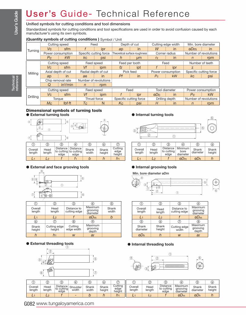
Use
r´s G
uide
www.tungaloyamerica.comG082
qw
e
r
t
yu
i
o
qw
e
r
t
yu
i
q
w
er
t
y u
q
w
e
r
t
y
� � � � �
L1 L2 f øDm b� �
h h1 w ar
� � � � � � �
L1 L2 f f1 b h h1
qw
e
r
r
e
t
yuqw
et
y
� � � � � � �
L1 L2 f - b h h1
Vc sfm f ipr ap in W in øDm in
Pc kW kc psi h μm rε in n rpm
Vc sfm Vf ipm fz ipt f ipr z
ap in ae in Pf in Pc kW kc psi
Q in3/min n rpm
� � � �
L1 L2 f øDm
� � �
øDs h w ar
� � � � � �
L1 L2 f øDm øDs h
� � � � � �
L1 L2 f øDm øDs h
Vc sfm Vf ipm f ipr øDc in Pc kW
Mc lbf·ft Tc N Kc psi H in n rpm
Tec
hnic
alre
fere
nce
User’s Guide- Technica l Reference
Min. bore diameter øDm
Maximum grooving diameter
Shankwidth
Shankheight
Cutting edgeheight
Cuttingedge width
Maximumgrooving
depth
Distance to cutting edge
Overall length
Headlength
Maximum grooving diameter
Shankheight
Distanceto cutting
edge
Shankdiameter
Overall length
Headlength
Maximum grooving diameter
Shankheight
Cutting edgewidth
Maximumgrooving
depth
Distance to cutting edge
Shankdiameter
Overall length
Headlength
Minimum bore
diameter
Distanceto cutting
edge
Shankdiameter
Shankheight
Overall length
Headlength
Cutting edgeheight
Distanceto cutting
edge
Distanceto cutting
edge
Overall length
Headlength
Shankwidth
Shankheight
Cutting edgeheight
Distanceto cutting
edge
Overall length
Headlength
Shoulderwidth
Shankwidth
Shankheight
Standardized symbols for cutting conditions and tool specifications are used in order to avoid confusion caused by each manufacturer’s using its own symbols.
(Quantity symbols of cutting conditions )
Dimensional symbols of turning tools� External turning tools
� External and face grooving tools � Internal grooving tools
� Internal threading tools� External threading tools
� Internal turning tools
Symbol / Unit
Turning
Cutting speed Feed Depth of cut Cutting edge width Min. bore diameter
Power consumption Specific cutting force Theoretical surface roughness Corner radius Number of revolutions
Cutting speed Feed speed Feed per tooth Feed Number of teeth
Axial depth of cut Radial depth of cut Pick feed Power consumption Specific cutting force
Chip removal rate Number of revolutions
Cutting speed Feed speed Feed Tool diameter Power consumption
Torque Thrust force Specific cutting force Drilling depth Number of revolutions
Milling
Drilling
Unified symbols for cutting conditions and tool dimensions
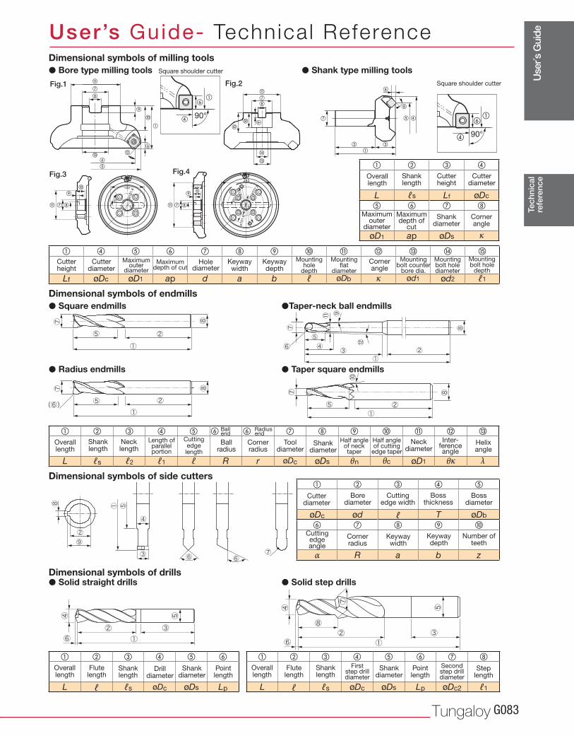
Use
r´s G
uide
Tungaloy G083
� � � �
L ℓs Lf øDc
� � �
øD1 ap øDs κ
� � � � � � �
L ℓ ℓs øDc øDs Lp øDc2 ℓ1
� � � � � �
L ℓ ℓs øDc øDs Lp
� � � � �
øDc ød ℓ T øDb
� � �
α R a b z
� � � � � � � � � �
Lf øDc øD1 ap d a b ℓ øDb κ ød1 ød2 ℓ1
� � � � � � � � � � �
L ℓs ℓ2 ℓ1 ℓ R r øDc øDs θn θc øD1 θκ λ
90°�
��
0
150
45° ø
101.6
45°
0
ø190
ø177.8
245
ø101.6
�
�
�
�
�
�
� �
�
�
�
��
�
�
�
�
��
�
90°
��
�
�� �
���
�
Tec
hnic
alre
fere
nce
User’s Guide- Technica l Reference
Cornerangle
Maximumdepth of
cut
Maximumouter
diameter
Cutter diameter
Cutterheight
Shankdiameter
Overall length
Shanklength
Drill diameter
First step drill diameter
Second step drill diameter
Shankdiameter
Shankdiameter
Overall length
Overall length
Flutelength
Flutelength
Shanklength
Shanklength
Pointlength
Steplength
Pointlength
Cornerangle
Helixangle
Inter-ference angle
Maximumdepth of cut
Maximumouter
diameter
Length of parallel portion
Mountinghole
depth
Mountingbolt counter
bore dia.
Mountingbolt holediameter
Cuttingedgelength
Cuttingedge width
Cuttingedgeangle
Half angle of neck taper
Half angle of cutting
edge taper
Mountingbolt hole
depth
Mountingflat
diameter
Cutter diameter
Cutter diameter
Bore diameter
Boss diameter
Boss thickness
Cutter height
Shankdiameter
Tooldiameter
Neckdiameter
Holediameter
Keywaywidth
Keywaywidth
Keywaydepth
Keywaydepth
Number of teeth
Overall length
Shanklength
Necklength
Ballradius
Ball Radiusend end
Cornerradius
Cornerradius
Dimensional symbols of milling tools
Dimensional symbols of drills
Dimensional symbols of side cutters
Dimensional symbols of endmills
� Bore type milling tools
� Solid straight drills
� Square endmills
� Radius endmills
� Solid step drills
�Taper-neck ball endmills
� Taper square endmills
Fig.1 Fig.2
Fig.3 Fig.4
Square shoulder cutter
Square shoulder cutter
� Shank type milling tools
www.tungaloyamerica.comG084
AlphanumericIndex
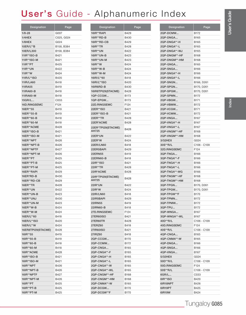
Use
r´s G
uide
Tungaloy G085
User’s Guide - A lphanumer ic Index
Ind
ex
Designation Page
1/8-28 G007
1/4HEX C025, G024
1/8HEX G024
10ER/L**B B158, B384
10ER/L300 B158, B384
11IR**ISO-B B421
11IR**ISO-M B421
11IR**PT B425
11IR**UN B422
11IR**W B424
11IR/L**ISO B420
11IR/LA60 B418
11IRA55 B419
11IRA60-B B418
11IRA60-M B418
15GR/L... C033
16D.RINGSEMC F124
16ER**55 B419
16ER**55-B B419
16ER**60-B B418
16ER**60-M B418
16ER**ACME B428
16ER**ISO-B B421
16ER**ISO-M B421
16ER**NPT B426
16ER**NPT-B B426
16ER**NPTF B427
16ER**NPT-M B426
16ER**PT B425
16ER**PT-B B425
16ER**PT-M B425
16ER**RAPI B429
16ER*RD-B B430
16ER**RD-CB B429
16ER**TR B428
16ER**UN B422
16ER**UN-B B423
16ER**UNJ B430
16ER**UN-M B423
16ER**W-B B424
16ER**W-M B424
16ER/L**60 B418
16ER/L**ISO B420
16ER/L**W B424
16ER8TPI29(STACME) B428
16IR**55 B419
16IR**55-B B419
16IR**60-B B418
16IR**60-M B418
16IR**ACME B428
16IR**ISO-B B421
16IR**ISO-M B421
16IR**NPT B426
16IR**NPT-B B426
16IR**NPTF B427
16IR**NPT-M B426
16IR**PT B425
16IR**PT-B B425
16IR**PT-M B425
Designation Page
16IR**RAPI B429
16IR**RD-B B430
16IR**RD-CB B429
16IR**TR B428
16IR**UN B422
16IR**UN-B B423
16IR**UN-M B423
16IR**W B424
16IR**W-B B424
16IR**W-M B424
16IR/L**60 B418
16IR/L**ISO B420
16IR6RD-B B430
16IR8TPI29(STACME) B428
1QP-CCGW... B173
1QP-EPGW... B173
22D.RINGSEMC F124
22ER**ISO B421
22ER**ISO-B B421
22ER**TR B428
22ER*ACME B428
22ER*TPI29(STACME) AH725 B428
22ER*UN B422
22ER*W B424
22ER/LN60 B418
22ER5BAPI B429
22ERN55 B419
22ERN60-B B418
22IR**ISO B421
22IR**TR B428
22IR*ACME B428
22IR*TPI29(STACME) AH725 B428
22IR*UN B422
22IR*W B424
22IR/LN60 B418
22IR5BAPI B429
22IRN55 B419
22IRN60-B B418
27D.RINGSEMC F124
27ER60ISO B421
27ER60TR B428
27ERZ60 B418
27IR60ISO B421
27IRZ60 B418
2QP-CCGW... B170
2QP-CCMW... B172
2QP-CNGA... B165
2QP-CNGA**-F B165
2QP-CNGA**-H B165
2QP-CNGA**-L B165
2QP-CNGA**-W B165
2QP-CNGA**-WL B165
2QP-CNGM**-HF B168
2QP-CNGM**-HM B168
2QP-CNMA**-W B165
2QP-DCGW... B170
2QP-DCGW**F B170
Designation Page
2QP-DCMW... B172
2QP-DNGA... B165
2QP-DNGA**-H B165
2QP-DNGA**-L B165
2QP-DNGA**-WJ B165
2QP-DNGM**-HF B168
2QP-DNGM**-HM B168
2QP-GNGA... B165
2QP-SNGA... B166
2QP-SNGA**-H B166
2QP-SNGA**-L B166
2QP-SNGN... B166, D261
2QP-SPGN... B170, D261
2QP-SPGW... B170, D261
2QP-SPMN... B172
2QP-VBGW... B171
2QP-VBMW... B172
2QP-VCGW... B171
2QP-VCMW... B172
2QP-VNGA... B167
2QP-VNGA**-H B167
2QP-VNGA**-L B167
2QP-VNGM**-HF B168
2QP-VNGM**-HM B168
3/32HEX G024
30S**R/L C106 - C109
32D.RINGSEMC F124
3QP-TNGA... B166
3QP-TNGA**-F B166
3QP-TNGA**-H B166
3QP-TNGA**-L B166
3QP-TNGA**-WG B166
3QP-TNGM**-HF B168
3QP-TNGM**-HM B168
3QP-TPGN... B170, D261
3QP-TPGW... B170, D261
3QP-TPGW**F B170
3QP-TPMN... B172
3QP-TPMW... B172
3QP-TPU... B172
3QP-WNGA... B167
3QP-WNGA**-WL B167
40D**R/L C106 - C109
40D.RINGSEMC F124
40S**R/L C106 - C109
4QP-CNGA... B165
4QP-CNMA**-W B165
4QP-DNGA... B166
4QP-SNGA... B166
4QP-VNGA... B167
5/32HEX G024
50D**R/L C106 - C109
50D.RINGSEMC F124
50S**R/L C106 - C109
6GR/L... C033
6IR**ISO B420
6IR18NPT B426
6IR19PT B425
6IR19W B424
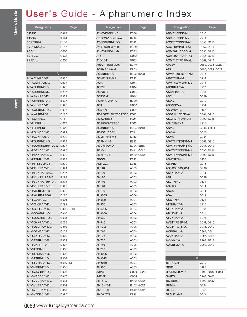
Use
r´s G
uide
www.tungaloyamerica.comG086
User’s Guide - A lphanumer ic IndexIn
dex
Designation Page
6IRA55 B419
6IRA60 B418
6QP-TNGA... B166
6QP-WNGA... B167
7GR/L... C033
8GR/L... C033
9GR/L... C033
A
A**-ACLNR/L*-D... B326
A**-ACLNR/L33... B294
A**-ADUNR/L*-D... B328
A**-ADUNR/L33... B296
A**-ASKNR/L*-D... B327
A**-ATFNR/L*-D... B327
A**-AVUNR/L*-D... B328
A**-AWLNR/L*-D... B326
A**-AWLNR/L33... B295
A**-CGTR/L... C111
A**-FLER/L... C024
A**-FLER/LT3 C023
A**-PCLNR/L**-D... B321
A**-PCLNR/L0904... B294
A**-PDUNR/L**-D... B324
A**-PDUNR/L1104-D250 B297
A**-PDZNR/L**-D... B325
A**-PSKNR/L**-D... B322
A**-PTFNR/L**-D... B323
A**-PTFNR/L1104... B296
A**-PTUNR/L**-D... B324
A**-PTUNR/L1104... B297
A**-PVUNR/L2.33-D... B298
A**-PVUNR/L1204-D... B298
A**-PVUNR/L16-D... B325
A**-PWLNR/L**-D... B322
A**-PWLNR/L0604... B295
A**-SCLCR/L... B301
A**-SCLCR/L**-D... B299
A**-SCLPR/L**-D... B303, B304
A**-SDQCR/L**-D... B316
A**-SDUCR/L**-D... B313
A**-SDXXR/L**-D... B288
A**-SDZCR/L**-D... B319
A**-SDZXR/L**-D... B289
A**-SEXPR/L**-D... B302
A**-SEZPR/L**-D... B321
A**-SSKPR**-D... B307
A**-STFCR/L... B308
A**-STFCR/L**-D... B308
A**-STFPR/L**-D... B309
A**-STUPR/L**-D... B310, B311
A**-SVJBR/L**-D... B306
A**-SVJCR/L**-D... B306
A**-SVQBR/L**-D... B317
A**-SVQCR/L**-D... B318
A**-SVUBR/L**-D... B314
A**-SVUCR/L**-D... B315
A**-SVZBR/L**-D... B320
Designation Page
A**-SVZCR/L**-D... B320
A**-SWLXR/L**-D... B288
A**-SWUBR/L**-D... B312
A**-SYQBR/L**-D... B329
A**-SYUBR/L**-D... B329
A16-1 G012
A16-1DT G012
A32S-PTUNR/L16 B340
ACKNR/L164-A B209
ACLNR/L**-A B202, B208
ACMT**PR-MJ D212
ACP... G014
ACP*S G014
ACP3L-E G014
ACP3S-E G014
ACRNR/L164-A B209
ACS... G007
ACS-*W G007
ADJ CAT** D2.756 ER32 F083
ADJC*ER32 F024
ADJHSKA**ER32 F065
ADJNR/L**-A B204, B210
ADJST**ER32 F091
ADMT**PR-MJ D212
ADPNN**-A B212
ADQNR/L**-A B206, B216
AE16-... B442, G012
AE16-**DT B442, G012
AECW... D212
AEMW... D212
AH110 A003
AH120 A003
AH130 A003
AH140 A003
AH170 A003
AH180 A003
AH3035 A004
AH3135 A004
AH330 A003
AH4035 A004
AH6030 A004
AH630 A003
AH645 A003
AH7025 A003
AH710 A003
AH725 A003
AH730 A003
AH740 A003
AH750 A003
AH8005 A003
AH8015 A003
AH9030 A004
AH905 A003
AJM5 G004, G028
AJM5F G004
AN16-... B442, G012
AN16-**DT B442, G012
AN16-*DT B442, G012
ANEA**TN D212
Designation Page
ANMT**PPPR-MJ D213
ANMT**PPPR-ML D213
AOGT07**PDFR-AJ D055, D213
AOGT18**PDFR-AJ D067, D214
AOMT07**PDPR-MJ D055, D213
AOMT07**PDPR-HJ D055, D213
AOMT18**PDPR-MJ D067, D214
AP08** E088, E091, G022
AP11** E088, E091, G022
APMR190616PR-MJ D215
APMT**PN-MJ D214
APMT120416PR-MJ D214
ARGNR/L**-A B217
ASBNR/L**-A B213
ASC... G009
ASD... G010
ASDNN**-A B214
ASG**N**-... D128
ASGT11**PDFR-AJ D061, D215
ASGT17**PDFR-AJ D090, D216
ASKNR/L**-A B215
ASM... G004, G028
ASM34L G028
ASM6 G004
ASMT11**PDPR-MJ D061, D215
ASMT11**PDPR-MS D061, D215
ASMT17**PDPR-MJ D090, D216
ASMT17**PDPR-MS D090, D216
ASN**R**M... D136
ASR420 G011
ASS422, 533, 634 G009
ASSNR/L**-A B214
AST... G008
ASV**N**-... D131
ASV222 G011
ASV322 G011
ASW... G011
ASW**N**-... D133
ATFNR/L**-A B215
ATGNR/L**-A B213
ATJNR/L**-A B211
ATQNR/L**-A B216
AVGT**PBER-MJ D051, D216
AVGT**PBFR-AJ D051, D216
AVJNR/L**-A B207, B211
AVQNR/L**-A B207, B217
AVVNN**-A B208, B212
AWLNR/L**-A B202, B210
B
B11 R/L-5 G019
BBB2... D167
B-CER/L16M16 B409, B433, C044
B-SER... B409, B433
BC-SER... B409, B433
BHM*-... G004
BLC... B346
BLD IP**/M7 G024
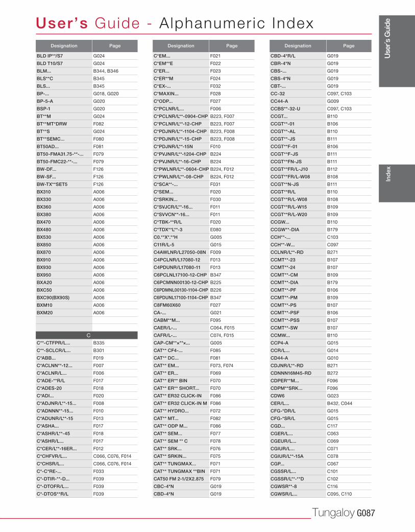
Use
r´s G
uide
Tungaloy G087
User’s Guide - A lphanumer ic Index
Ind
ex
Designation Page
BLD IP**/S7 G024
BLD T10/S7 G024
BLM... B344, B346
BLS**C B345
BLS... B345
BP-... G018, G020
BP-5-A G020
BSP-1 G020
BT**M G024
BT**MT*DRW F082
BT**S G024
BT**SEMC... F080
BT50AD... F081
BT50-FMA31.75-**-... F079
BT50-FMC22-**-... F079
BW-DF... F126
BW-SF... F126
BW-TX**SET5 F126
BX310 A006
BX330 A006
BX360 A006
BX380 A006
BX470 A006
BX480 A006
BX530 A006
BX850 A006
BX870 A006
BX910 A006
BX930 A006
BX950 A006
BXA20 A006
BXC50 A006
BXC90(BX90S) A006
BXM10 A006
BXM20 A006
C
C**-CTFPR/L... B335
C**-SCLCR/L... B301
C*ABB... F019
C*ACLNN**-12... F007
C*ACLNR/L... F006
C*ADE-**R/L F017
C*ADES-20 F018
C*ADI... F020
C*ADJNR/L**-15... F008
C*ADNNN**-15... F010
C*ADUNR/L**-15 F013
C*ASHA... F017
C*ASHR/L**-45 F018
C*ASHR/L... F017
C*CER/L**-16ER... F012
C*CHFVR/L... C066, C076, F014
C*CHSR/L... C066, C076, F014
C*-C*RE-... F033
C*-DTIR-**-D... F039
C*-DTOFR/L... F039
C*-DTOS**R/L F039
Designation Page
C*EM... F021
C*EM**E F022
C*ER... F023
C*ER**M F024
C*EX-... F032
C*MAXIN... F028
C*ODP... F027
C*PCLNR/L... F006
C*PCLNR/L**-0904-CHP B223, F007
C*PCLNR/L**-12-CHP B223, F007
C*PDJNR/L**-1104-CHP B223, F008
C*PDJNR/L**-15-CHP B223, F008
C*PDJNR/L**-15N F010
C*PVJNR/L**-1204-CHP B224
C*PVJNR/L**-16-CHP B224
C*PWLNR/L**-0604-CHP B224, F012
C*PWLNR/L**-08-CHP B224, F012
C*SCA**-... F031
C*SEM... F020
C*SRKIN... F030
C*SVJCR/L**-16... F011
C*SVVCN**-16... F011
C*TBK-**R/L F020
C*TDX**L**-3 E080
C0.**X*.**H G005
C11R/L-5 G015
C4AWLNR/L27050-08N F009
C4PCLNR/L17080-12 F013
C4PDUNR/L17080-11 F013
C6PCLNL17100-12-CHP B347
C6PCMNN00130-12-CHP B225
C6PDMNL00130-1104-CHP B226
C6PDUNL17100-1104-CHP B347
C8FM60X60 F027
CA-... G021
CABM**M... F095
CAER/L-... C064, F015
CAFR/L-... C074, F015
CAP-CM**×**×... G005
CAT** CF4-... F085
CAT** DC... F081
CAT** EM... F073, F074
CAT** ER... F069
CAT** ER** BIN F070
CAT** ER** SHORT... F070
CAT** ER32 CLICK-IN F086
CAT** ER32 CLICK-IN M F086
CAT** HYDRO... F072
CAT** MT... F082
CAT** ODP M... F086
CAT** SEM... F077
CAT** SEM ** C F078
CAT** SRK... F076
CAT** SRKIN... F075
CAT** TUNGMAX... F071
CAT** TUNGMAX **BIN F071
CAT50 FM 2-1/2X2.875 F079
CBC-4*N G019
CBD-4*N G019
Designation Page
CBD-4*R/L G019
CBR-4*N G019
CBS-... G019
CBS-4*N G019
CBT-... G019
CC-32 C097, C103
CC44-A G009
CCBS**-32-U C097, C103
CCGT... B110
CCGT**-01 B106
CCGT**-AL B110
CCGT**-JS B111
CCGT**F-01 B106
CCGT**F-JS B111
CCGT**FN-JS B111
CCGT**FR/L-J10 B112
CCGT**FR/L-W08 B108
CCGT**N-JS B111
CCGT**R/L B110
CCGT**R/L-W08 B108
CCGT**R/L-W15 B109
CCGT**R/L-W20 B109
CCGW... B110
CCGW**-DIA B179
CCH**-... C103
CCH**-W... C097
CCLNR/L**-RD B271
CCMT**-23 B107
CCMT**-24 B107
CCMT**-CM B109
CCMT**-DIA B179
CCMT**-PF B106
CCMT**-PM B109
CCMT**-PS B107
CCMT**-PSF B106
CCMT**-PSS B107
CCMT**-SW B107
CCMW... B110
CCP4-A G015
CCR/L... G014
CD44-A G010
CDJNR/L**-RD B271
CDNNN16M45-RD B272
CDPER**M... F096
CDPM**SRK... F096
CDW6 G023
CER/L... B432, C044
CFG-*DR/L G015
CFG-*SR/L G015
CGD... C117
CGER/L... C063
CGEUR/L... C069
CGIUR/L... C071
CGIUR/L**-15A C078
CGP... C067
CGSSR/L... C101
CGSSR/L**-**D C102
CGWSR**-8 C116
CGWSR/L... C095, C110
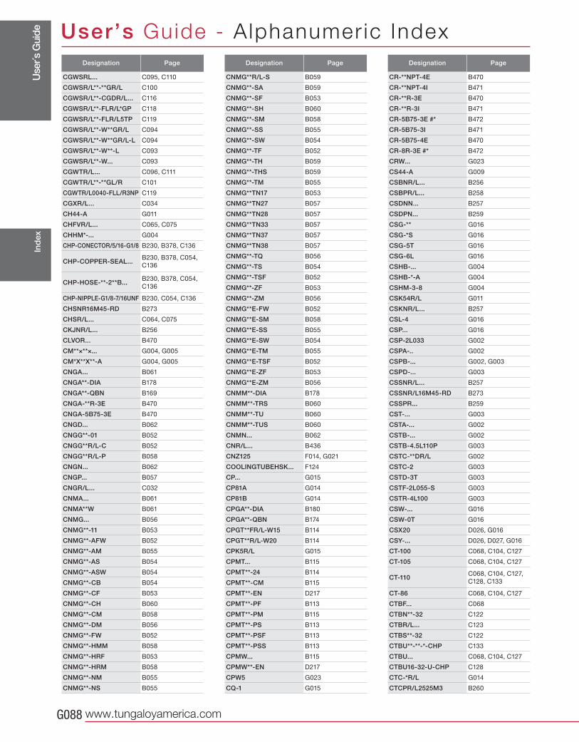
Use
r´s
Guid
e
www.tungaloyamerica.comG088
User’s Guide - A lphanumer ic IndexIn
dex
Designation Page
CGWSRL... C095, C110
CGWSR/L**-**GR/L C100
CGWSR/L**-CGDR/L... C116
CGWSR/L**-FLR/L*GP C118
CGWSR/L**-FLR/L5TP C119
CGWSR/L**-W**GR/L C094
CGWSR/L**-W**GR/L-L C094
CGWSR/L**-W**-L C093
CGWSR/L**-W... C093
CGWTR/L... C096, C111
CGWTR/L**-**GL/R C101
CGWTR/L0040-FLL/R3NP C119
CGXR/L... C034
CH44-A G011
CHFVR/L... C065, C075
CHHM*-... G004
CHP-CONECTOR/5/16-G1/8 B230, B378, C136
CHP-COPPER-SEAL...B230, B378, C054,
C136
CHP-HOSE-**-2**B...B230, B378, C054,
C136
CHP-NIPPLE-G1/8-7/16UNF B230, C054, C136
CHSNR16M45-RD B273
CHSR/L... C064, C075
CKJNR/L... B256
CLVOR... B470
CM**×**×... G004, G005
CM*X**X**-A G004, G005
CNGA... B061
CNGA**-DIA B178
CNGA**-QBN B169
CNGA-**R-3E B470
CNGA-5B75-3E B470
CNGD... B062
CNGG**-01 B052
CNGG**R/L-C B052
CNGG**R/L-P B058
CNGN... B062
CNGP... B057
CNGR/L... C032
CNMA... B061
CNMA**W B061
CNMG... B056
CNMG**-11 B053
CNMG**-AFW B052
CNMG**-AM B055
CNMG**-AS B054
CNMG**-ASW B054
CNMG**-CB B054
CNMG**-CF B053
CNMG**-CH B060
CNMG**-CM B058
CNMG**-DM B056
CNMG**-FW B052
CNMG**-HMM B058
CNMG**-HRF B053
CNMG**-HRM B058
CNMG**-NM B055
CNMG**-NS B055
Designation Page
CNMG**R/L-S B059
CNMG**-SA B059
CNMG**-SF B053
CNMG**-SH B060
CNMG**-SM B058
CNMG**-SS B055
CNMG**-SW B054
CNMG**-TF B052
CNMG**-TH B059
CNMG**-THS B059
CNMG**-TM B055
CNMG**TN17 B053
CNMG**TN27 B057
CNMG**TN28 B057
CNMG**TN33 B057
CNMG**TN37 B057
CNMG**TN38 B057
CNMG**-TQ B056
CNMG**-TS B054
CNMG**-TSF B052
CNMG**-ZF B053
CNMG**-ZM B056
CNMG**E-FW B052
CNMG**E-SM B058
CNMG**E-SS B055
CNMG**E-SW B054
CNMG**E-TM B055
CNMG**E-TSF B052
CNMG**E-ZF B053
CNMG**E-ZM B056
CNMM**-DIA B178
CNMM**-TRS B060
CNMM**-TU B060
CNMM**-TUS B060
CNMN... B062
CNR/L... B436
CNZ125 F014, G021
COOLINGTUBEHSK... F124
CP... G015
CP81A G014
CP81B G014
CPGA**-DIA B180
CPGA**-QBN B174
CPGT**FR/L-W15 B114
CPGT**R/L-W20 B114
CPK5R/L G015
CPMT... B115
CPMT**-24 B114
CPMT**-CM B115
CPMT**-EN D217
CPMT**-PF B113
CPMT**-PM B115
CPMT**-PS B113
CPMT**-PSF B113
CPMT**-PSS B113
CPMW... B115
CPMW**-EN D217
CPW5 G023
CQ-1 G015
Designation Page
CR-**NPT-4E B470
CR-**NPT-4I B471
CR-**R-3E B470
CR-**R-3I B471
CR-5B75-3E #* B472
CR-5B75-3I B471
CR-5B75-4E B470
CR-8R-3E #* B472
CRW... G023
CS44-A G009
CSBNR/L... B256
CSBPR/L... B258
CSDNN... B257
CSDPN... B259
CSG-** G016
CSG-*S G016
CSG-5T G016
CSG-6L G016
CSHB-... G004
CSHB-*-A G004
CSHM-3-8 G004
CSK54R/L G011
CSKNR/L... B257
CSL-4 G016
CSP... G016
CSP-2L033 G002
CSPA-.. G002
CSPB-... G002, G003
CSPD-... G003
CSSNR/L... B257
CSSNR/L16M45-RD B273
CSSPR... B259
CST-... G003
CSTA-... G002
CSTB-... G002
CSTB-4.5L110P G003
CSTC-**DR/L G002
CSTC-2 G003
CSTD-3T G003
CSTF-2L055-S G003
CSTR-4L100 G003
CSW-... G016
CSW-0T G016
CSX20 D026, G016
CSY-... D026, D027, G016
CT-100 C068, C104, C127
CT-105 C068, C104, C127
CT-110C068, C104, C127,
C128, C133
CT-86 C068, C104, C127
CTBF... C068
CTBN**-32 C122
CTBR/L... C123
CTBS**-32 C122
CTBU**-**-*-CHP C133
CTBU... C068, C104, C127
CTBU16-32-U-CHP C128
CTC-*R/L G014
CTCPR/L2525M3 B260
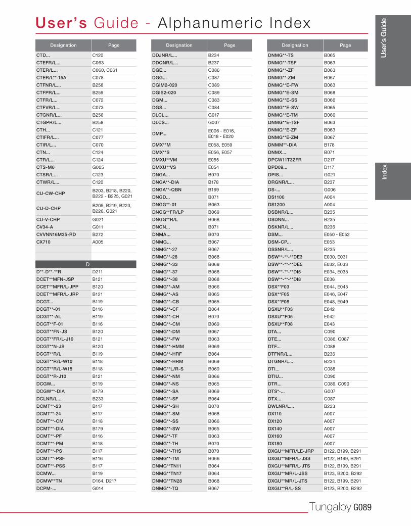
Use
r´s G
uide
Tungaloy G089
User’s Guide - A lphanumer ic Index
Ind
ex
Designation Page
CTD... C120
CTEFR/L... C063
CTER/L... C060, C061
CTER/L**-15A C078
CTFNR/L... B258
CTFPR/L... B259
CTFR/L... C072
CTFVR/L... C073
CTGNR/L... B256
CTGPR/L... B258
CTH... C121
CTIFR/L... C077
CTIR/L... C070
CTN... C124
CTR/L... C124
CTS-M6 G005
CTSR/L... C123
CTWR/L... C120
CU-CW-CHP B203, B218, B220,
B222 - B225, G021
CU-D-CHP B205, B219, B223,
B226, G021
CU-V-CHP G021
CV34-A G011
CVVNN16M35-RD B272
CX710 A005
D
D**-D**-**R D211
DCET**MFN-JSP B121
DCET**MFR/L-JPP B120
DCET**MFR/L-JRP B121
DCGT... B119
DCGT**-01 B116
DCGT**-AL B119
DCGT**F-01 B116
DCGT**FN-JS B120
DCGT**FR/L-J10 B121
DCGT**N-JS B120
DCGT**R/L B119
DCGT**R/L-W10 B118
DCGT**R/L-W15 B118
DCGT**R-J10 B121
DCGW... B119
DCGW**-DIA B179
DCLNR/L... B233
DCMT**-23 B117
DCMT**-24 B117
DCMT**-CM B118
DCMT**-DIA B179
DCMT**-PF B116
DCMT**-PM B118
DCMT**-PS B117
DCMT**-PSF B116
DCMT**-PSS B117
DCMW... B119
DCMW**TN D164, D217
DCPM-... G014
Designation Page
DDJNR/L... B234
DDQNR/L... B237
DGE... C086
DGG... C087
DGIM2-020 C089
DGIS2-020 C089
DGM... C083
DGS... C084
DLCL... G017
DLCS... G007
DMP... E006 - E016,
E018 - E020
DMX**M E058, E059
DMX**S E056, E057
DMXU**VM E055
DMXU**VS E054
DNGA... B070
DNGA**-DIA B178
DNGA**-QBN B169
DNGD... B071
DNGG**-01 B063
DNGG**FR/LP B069
DNGG**R/L B068
DNGN... B071
DNMA... B070
DNMG... B067
DNMG**-27 B067
DNMG**-28 B068
DNMG**-33 B068
DNMG**-37 B068
DNMG**-38 B068
DNMG**-AM B066
DNMG**-AS B065
DNMG**-CB B065
DNMG**-CF B064
DNMG**-CH B070
DNMG**-CM B069
DNMG**-DM B067
DNMG**-FW B063
DNMG**-HMM B069
DNMG**-HRF B064
DNMG**-HRM B069
DNMG**L/R-S B069
DNMG**-NM B066
DNMG**-NS B065
DNMG**-SA B069
DNMG**-SF B064
DNMG**-SH B070
DNMG**-SM B068
DNMG**-SS B066
DNMG**-SW B065
DNMG**-TF B063
DNMG**-TH B070
DNMG**-THS B070
DNMG**-TM B066
DNMG**TN11 B064
DNMG**TN17 B064
DNMG**TN28 B068
DNMG**-TQ B067
Designation Page
DNMG**-TS B065
DNMG**-TSF B063
DNMG**-ZF B063
DNMG**-ZM B067
DNMG**E-FW B063
DNMG**E-SM B068
DNMG**E-SS B066
DNMG**E-SW B065
DNMG**E-TM B066
DNMG**E-TSF B063
DNMG**E-ZF B063
DNMG**E-ZM B067
DNMM**-DIA B178
DNMX... B071
DPCW11T3ZFR D217
DPD09... D117
DPIS... G021
DRGNR/L... B237
DS-... G006
DS1100 A004
DS1200 A004
DSBNR/L... B235
DSDNN... B235
DSKNR/L... B236
DSM... E050 - E052
DSM-CP... E053
DSSNR/L... B235
DSW**-**-**DE3 E030, E031
DSW**-**-**DE5 E032, E033
DSW**-**-**DI5 E034, E035
DSW**-**-**DI8 E036
DSX**F03 E044, E045
DSX**F05 E046, E047
DSX**F08 E048, E049
DSXU**F03 E042
DSXU**F05 E042
DSXU**F08 E043
DTA... C090
DTE... C086, C087
DTF... C088
DTFNR/L... B236
DTGNR/L... B234
DTI... C088
DTIU... C090
DTR... C089, C090
DTS*-... G007
DTX... C087
DWLNR/L... B233
DX110 A007
DX120 A007
DX140 A007
DX160 A007
DX180 A007
DXGU**MFR/LE-JRP B122, B199, B291
DXGU**MFR/L-JSS B122, B199, B291
DXGU**MFR/L-JTS B122, B199, B291
DXGU**MR/L-JSS B123, B200, B292
DXGU**MR/L-JTS B122, B199, B291
DXGU**R/L-SS B123, B200, B292
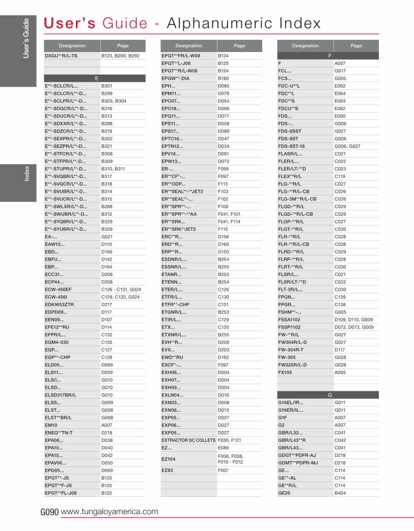
Use
r´s G
uide
www.tungaloyamerica.comG090
User’s Guide - A lphanumer ic IndexIn
dex
Designation Page
DXGU**R/L-TS B123, B200, B292
E
E**-SCLCR/L... B301
E**-SCLCR/L**-D... B299
E**-SCLPR/L**-D... B303, B304
E**-SDQCR/L**-D... B316
E**-SDUCR/L**-D... B313
E**-SDXXR/L**-D... B288
E**-SDZCR/L**-D... B319
E**-SEXPR/L**-D... B302
E**-SEZPR/L**-D... B321
E**-STFCR/L**-D... B308
E**-STFPR/L**-D... B309
E**-STUPR/L**-D... B310, B311
E**-SVQBR/L**-D... B317
E**-SVQCR/L**-D... B318
E**-SVUBR/L**-D... B314
E**-SVUCR/L**-D... B315
E**-SWLXR/L**-D... B288
E**-SWUBR/L**-D... B312
E**-SYQBR/L**-D... B329
E**-SYUBR/L**-D... B329
EA-... G021
EAW13... D110
EBD... D166
EBFU... D142
EBP... D164
ECC31... D206
ECP44... D208
ECW-456EF C126 - C131, G024
ECW-456I C129, C132, G024
EDKW53ZTR D217
EDPD09... D117
EEN09... D107
EFE12**RU D114
EFPR/L... C132
EGM4-030 C135
EGP... C127
EGP**-CHP C128
ELD05... D069
ELS11... D059
ELSC... G010
ELSD... G010
ELSD317BR/L G010
ELSS... G009
ELST... G008
ELST**BR/L G008
EM10 A007
ENEQ**TN-T D218
EPA06... D038
EPA10... D040
EPA15... D042
EPAV06... D050
EPD05... D069
EPGT**-JS B125
EPGT**F-JS B125
EPGT**FL-J08 B125
Designation Page
EPGT**FR/L-W08 B124
EPGT**L-J08 B125
EPGT**R/L-W08 B124
EPGW**-DIA B180
EPH... D085
EPM11... D079
EPO07... D054
EPO18... D066
EPQ11... D077
EPS11... D058
EPS17... D089
EPTC16... D047
EPTN12... D034
EPV16... D081
EPW13... D073
ER-... F099
ER**CF*-... F097
ER**ODP... F113
ER**SEAL**-**JET2 F103
ER**SEAL**-... F102
ER**SPR**-... F100
ER**SPR**-**AA F041, F101
ER**SRK... F041, F114
ER**SRK**JET2 F115
ERC**R... D156
ERD**R... D160
ERP**R... D150
ESDNR/L... B254
ESSNR/L... B255
ETANR... B253
ETENN... B254
ETER/L... C126
ETFR/L... C130
ETFR**-CHP C131
ETGNR/L... B253
ETIR/L... C129
ETX... C135
ETXNR/L... B255
EVH**R... D200
EVX... D203
EWD**RU D162
EXCF*-... F097
EXH06... D004
EXH07... D004
EXH09... D004
EXLN04... D016
EXN03... D008
EXN06... D013
EXP05... D027
EXP06... D027
EXP09... D027
EXTRACTOR SC COLLETS F030, F121
EZ... E086
EZ104 F006, F008,
F010 - F012
EZ83 F007
Designation Page
F
F A007
FCL... G017
FCS... G005
FDC-U**L E062
FDC**L E064
FDC**S E063
FDCU**S E062
FDS... E060
FDS-... G006
FDS-8SST G027
FDS-8ST G006
FDS-8ST-18 G006, G027
FLASR/L... C021
FLER/L... C022
FLER/LT-**D C023
FLEX**R/L C119
FLG-**R/L C027
FLG-**R/L-CB C026
FLG-3M**R/L-CB C026
FLGD-**R/L C029
FLGD-**R/L-CB C029
FLGP-**R/L C027
FLGT-**R/L C030
FLR-**R/L C028
FLR-**R/L-CB C028
FLRD-**R/L C029
FLRP-**R/L C028
FLRT-**R/L C030
FLSR/L... C021
FLSR/LT-**D C022
FLT-3R/L... C030
FPGN... C139
FPGR... C138
FSHM**-... G005
FSSA1102 D109, D110, G009
FSSP1102 D072, D073, G009
FW-**R/L G027
FW304R/L-D G027
FW-304R-T D117
FW-305 G028
FW325R/L-D G028
FX105 A005
G
G16EL/IR... G011
G16ER/IL... G011
G1F A007
G2 A007
GBR/L32... C041
GBR/L43**R C042
GBR/L43... C041
GDGT**PDFR-AJ D218
GDMT**PDPR-MJ D218
GE... C114
GE**-AL C114
GE**R/L C114
GE20 B404
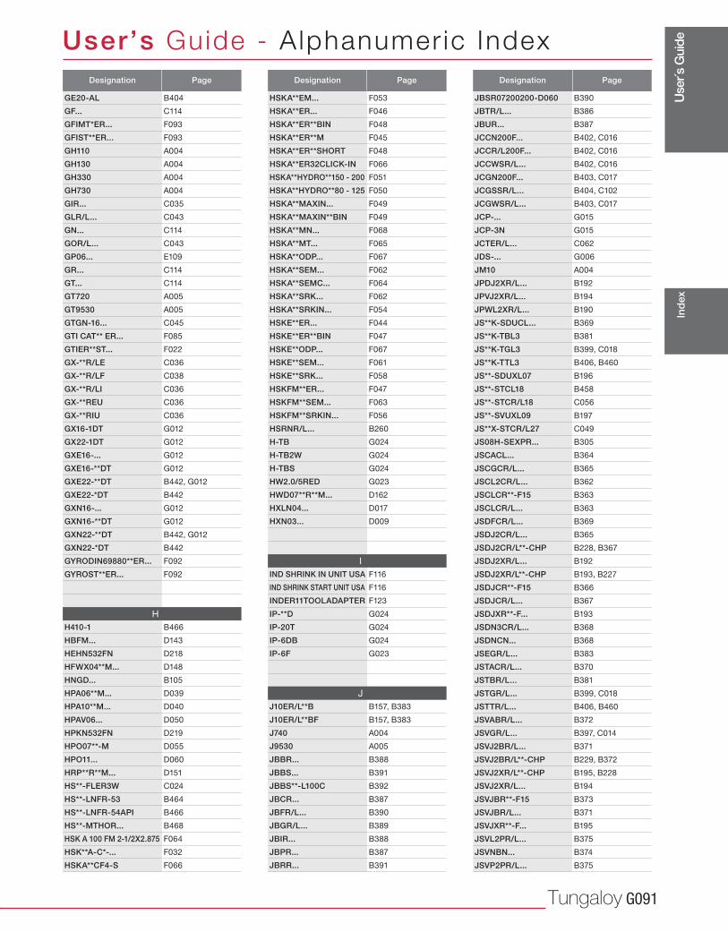
Use
r´s G
uide
Tungaloy G091
User’s Guide - A lphanumer ic Index
Ind
ex
Designation Page
GE20-AL B404
GF... C114
GFIMT*ER... F093
GFIST**ER... F093
GH110 A004
GH130 A004
GH330 A004
GH730 A004
GIR... C035
GLR/L... C043
GN... C114
GOR/L... C043
GP06... E109
GR... C114
GT... C114
GT720 A005
GT9530 A005
GTGN-16... C045
GTI CAT** ER... F085
GTIER**ST... F022
GX-**R/LE C036
GX-**R/LF C038
GX-**R/LI C036
GX-**REU C036
GX-**RIU C036
GX16-1DT G012
GX22-1DT G012
GXE16-... G012
GXE16-**DT G012
GXE22-**DT B442, G012
GXE22-*DT B442
GXN16-... G012
GXN16-**DT G012
GXN22-**DT B442, G012
GXN22-*DT B442
GYRODIN69880**ER... F092
GYROST**ER... F092
H
H410-1 B466
HBFM... D143
HEHN532FN D218
HFWX04**M... D148
HNGD... B105
HPA06**M... D039
HPA10**M... D040
HPAV06... D050
HPKN532FN D219
HPO07**-M D055
HPO11... D060
HRP**R**M... D151
HS**-FLER3W C024
HS**-LNFR-53 B464
HS**-LNFR-54API B466
HS**-MTHOR... B468
HSK A 100 FM 2-1/2X2.875 F064
HSK**A-C*-... F032
HSKA**CF4-S F066
Designation Page
HSKA**EM... F053
HSKA**ER... F046
HSKA**ER**BIN F048
HSKA**ER**M F045
HSKA**ER**SHORT F048
HSKA**ER32CLICK-IN F066
HSKA**HYDRO**150 - 200 F051
HSKA**HYDRO**80 - 125 F050
HSKA**MAXIN... F049
HSKA**MAXIN**BIN F049
HSKA**MN... F068
HSKA**MT... F065
HSKA**ODP... F067
HSKA**SEM... F062
HSKA**SEMC... F064
HSKA**SRK... F062
HSKA**SRKIN... F054
HSKE**ER... F044
HSKE**ER**BIN F047
HSKE**ODP... F067
HSKE**SEM... F061
HSKE**SRK... F058
HSKFM**ER... F047
HSKFM**SEM... F063
HSKFM**SRKIN... F056
HSRNR/L... B260
H-TB G024
H-TB2W G024
H-TBS G024
HW2.0/5RED G023
HWD07**R**M... D162
HXLN04... D017
HXN03... D009
I
IND SHRINK IN UNIT USA F116
IND SHRINK START UNIT USA F116
INDER11TOOLADAPTER F123
IP-**D G024
IP-20T G024
IP-6DB G024
IP-6F G023
J
J10ER/L**B B157, B383
J10ER/L**BF B157, B383
J740 A004
J9530 A005
JBBR... B388
JBBS... B391
JBBS**-L100C B392
JBCR... B387
JBFR/L... B390
JBGR/L... B389
JBIR... B388
JBPR... B387
JBRR... B391
Designation Page
JBSR07200200-D060 B390
JBTR/L... B386
JBUR... B387
JCCN200F... B402, C016
JCCR/L200F... B402, C016
JCCWSR/L... B402, C016
JCGN200F... B403, C017
JCGSSR/L... B404, C102
JCGWSR/L... B403, C017
JCP-... G015
JCP-3N G015
JCTER/L... C062
JDS-... G006
JM10 A004
JPDJ2XR/L... B192
JPVJ2XR/L... B194
JPWL2XR/L... B190
JS**K-SDUCL... B369
JS**K-TBL3 B381
JS**K-TGL3 B399, C018
JS**K-TTL3 B406, B460
JS**-SDUXL07 B196
JS**-STCL18 B458
JS**-STCR/L18 C056
JS**-SVUXL09 B197
JS**X-STCR/L27 C049
JS08H-SEXPR... B305
JSCACL... B364
JSCGCR/L... B365
JSCL2CR/L... B362
JSCLCR**-F15 B363
JSCLCR/L... B363
JSDFCR/L... B369
JSDJ2CR/L... B365
JSDJ2CR/L**-CHP B228, B367
JSDJ2XR/L... B192
JSDJ2XR/L**-CHP B193, B227
JSDJCR**-F15 B366
JSDJCR/L... B367
JSDJXR**-F... B193
JSDN3CR/L... B368
JSDNCN... B368
JSEGR/L... B383
JSTACR/L... B370
JSTBR/L... B381
JSTGR/L... B399, C018
JSTTR/L... B406, B460
JSVABR/L... B372
JSVGR/L... B397, C014
JSVJ2BR/L... B371
JSVJ2BR/L**-CHP B229, B372
JSVJ2XR/L**-CHP B195, B228
JSVJ2XR/L... B194
JSVJBR**-F15 B373
JSVJBR/L... B371
JSVJXR**-F... B195
JSVL2PR/L... B375
JSVNBN... B374
JSVP2PR/L... B375
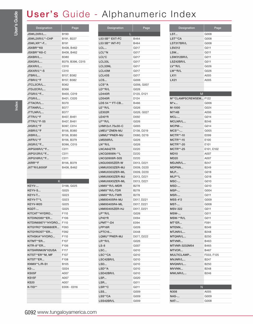
Use
r´s G
uide
www.tungaloyamerica.comG092
User’s Guide - A lphanumer ic IndexIn
dex
Designation Page
JSWL2XR/L... B190
JSWL2XR/L**-CHP B191, B227
JSWLXR**-F... B191
JSXBR**K8 B408, B462
JSXBR**K8-C B408, B462
JSXBR/L... B380
JSXGR/L... B379, B396, C015
JSXXR/L... C010
JSXXR/L**-S C010
JTBR/L... B157, B382
JTBR/L**F B157, B382
JTCL2CR/L... B362
JTDJ2CR/L... B366
JTGR/L**F... B400, C019
JTGR/L... B401, C020
JTTACR/L... B370
JTTANR/L... B377
JTTLNR/L... B377
JTTR/L**F B407, B461
JTTR/L**F-55 B407, B461
JVGR/L**F B397, C014
JXBR/L**F B156, B380
JXBR/L... B156, B380
JXFR/L**F B156, B379
JXGR/L**F... B396, C015
JXPG06R/L**F... C011
JXPG12R/L**F... C011
JXPG16R/L**F... C011
JXRR**F B156, B379
JXT*R/L6000F B408, B462
K
KEYV-... D198, G025
KEYV-S... G025
KEYV-T... G023
KEYV-T**L G023
KEYV-W20 G025
KGDT-... G025
KITCAT**HYDRO... F110
KITDIN2080**ER... F106
KITDIN69871**HYDRO... F110
KITGYRO**D69880ER... F093
KITGYROST**ER... F092
KITHSKA**HYDRO... F110
KITMT**ER... F107
KITR-8**ER... F106
KITSHRINKIN*V2USA F117
KITST**ER**M, MF F107
KITST**ER... F108
KNMX**L/R-S1 B105
KS-... G024
KS05F A007
KS15F A007
KS20 A007
K-TID** E006 - E016
Designation Page
L
L53 5B** EXT-FC B464
L53 5B** INT-FC B464
LCL... G017
LCL**N G017
LCL*C G017
LCL33L G017
LCL33NL G017
LCL43M G017
LCL43S G017
LCS... G006
LCS**A G006, G007
LD**R/L G026
LD440R D120, D121
LD540R D124
LDS 54 ** FT-CB... B466
LE**R/L G026
LE302R G026, G027
LE40*R D092
LF**R/L G026
LHM12x1.75x30-C G005
LMEU**ZNEN-MJ D138, D219
LMMU**PNER-MJ D080, D219
LMS56R/L G026
LN**R/L G026
LNCA64ZTR D220
LNCQ0906N-**L D220
LNCQ0906R-50S D220
LNGU06X5ZER-W D013, D221
LNMU0303ZER-MJ D009, D220
LNMU0303ZER-ML D009, D220
LNMU06X5ZER-MJ D013, D221
LNMU06X5ZER-ML D013, D221
LNMX**R/L-MDR B278
LNMX**R/L-TDR B278
LNMX**R/L-TWR B278
LNMX0405R4-MJ D017, D221
LNMX0405R4-ML D017, D221
LNMX0405ZER-HJ D017, D221
LP**R/L G026
LP40*R D094
LPMT**-D4 E094
LPP16R G026
LPTC16... D048
LQMU**PNER-MJ D077, D222
LR**R/L G026
LS-8 G007
LSC... G010
LSC**CA G010
LSC42BR/L G010
LSD... G010
LSD**A G010
LSD42BR/L G010
LSP... G020
LSR... G011
LSR**C G011
LSS... G009
LSS**CA G009
LSS42BR/L G009
Designation Page
LST... G008
LST**CA G008
LST317BR/L G008
LSV212 G011
LSW... G011
LSW312BR/L G011
LSZ42BR/L G011
LV**R/L G026
LW**R/L G026
LX11 A005
LX21 A005
M
M**CLAMPSCREWSEM... F122
M*×... G006
M-1000 G024
M714B A006
MCL-... G014
MCLNR/L... B246
MCPM-... G014
MCS**-... G005
MCTR**-10 E099
MCTR**-15 E100
MCTR**-20 E101
MCTR**-25 E101, E102
MD10 A007
MD20 A007
MDJNR/L... B247
MDPNN... B249
MLP... G018
MLP**L G018
MSC-... G010
MSD-... G010
MSP-... G004
MSR-... G011
MSS-4*2 G009
MST-... G008
MSV-322 G011
MSW-... G011
MSW-**R/L G011
MT*ER... F091
MTENN... B249
MTJNR/L... B248
MTQNR/L... B250
MTVNR... B463
MTVNR-3232M54 B465
MTVOR... B467
MULTICLAMP... F033, F125
MVJNR/L... B247
MVQNR/L... B250
MVVNN... B248
MWLNR/L... B246
N
N308 A005
NAS-... G009
NAT-... G008
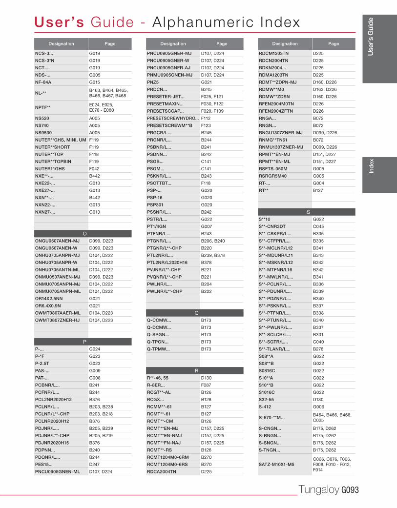
Use
r´s G
uide
Tungaloy G093
User’s Guide - A lphanumer ic Index
Ind
ex
Designation Page
NCS-3... G019
NCS-3*N G019
NCT-... G019
NDS-... G005
NF-84A G015
NL-** B463, B464, B465,
B466, B467, B468
NPTF** E024, E025,
E076 - E080
NS520 A005
NS740 A005
NS9530 A005
NUTER**GHS, MINI, UM F119
NUTER**SHORT F119
NUTER**TOP F118
NUTER**TOPBIN F119
NUTER11GHS F042
NXE**-... B442
NXE22-... G013
NXE27-... G013
NXN**-... B442
NXN22-... G013
NXN27-... G013
O
ONGU0507ANEN-MJ D099, D223
ONGU0507ANEN-W D099, D223
ONHU0705ANPN-MJ D104, D222
ONHU0705ANPR-W D104, D222
ONHU0705ANTN-ML D104, D222
ONMU0507ANEN-MJ D099, D223
ONMU0705ANPN-MJ D104, D222
ONMU0705ANPN-ML D104, D222
OR14X2.5NN G021
OR6.4X0.9N G021
OWMT0807AAER-ML D104, D223
OWMT0807ZNER-HJ D104, D223
P
P-... G024
P-*F G023
P-2.5T G023
PAS-... G009
PAT-... G008
PCBNR/L... B241
PCFNR/L... B244
PCL2NR2020H12 B376
PCLNR/L... B203, B238
PCLNR/L**-CHP B203, B218
PCLNR2020H12 B376
PDJNR/L... B205, B239
PDJNR/L**-CHP B205, B219
PDJNR2020H15 B376
PDPNN... B240
PDQNR/L... B244
PES15... D247
PNCU0905GNEN-ML D107, D224
Designation Page
PNCU0905GNER-MJ D107, D224
PNCU0905GNER-W D107, D224
PNCU0905GNFR-AJ D107, D224
PNMU0905GNEN-MJ D107, D224
PNZ5 G021
PRDCN... B245
PRESETER-JET... F025, F121
PRESETMAXIN... F030, F122
PRESETSCCAP... F029, F109
PRESETSCREWHYDRO... F112
PRESETSCREWM**B F123
PRGCR/L... B245
PRGNR/L... B244
PSBNR/L... B241
PSDNN... B242
PSGB... C141
PSGM... C141
PSKNR/L... B243
PSOTTBT... F118
PSP-... G020
PSP-16 G020
PSP301 G020
PSSNR/L... B242
PSTR/L... G022
PT1/4GN G007
PTFNR/L... B243
PTGNR/L... B206, B240
PTGNR/L**-CHP B220
PTL2NR/L... B239, B378
PTL2NR/L2020H16 B378
PVJNR/L**-CHP B221
PVQNR/L**-CHP B221
PWLNR/L... B204
PWLNR/L**-CHP B222
Q
Q-CCMW... B173
Q-DCMW... B173
Q-SPGN... B173
Q-TPGN... B173
Q-TPMW... B173
R
R**-46, 55 D130
R-8ER... F087
RCGT**-AL B126
RCGX... B128
RCMM**-61 B127
RCMT**-61 B127
RCMT**-CM B126
RCMT**EN-MJ D157, D225
RCMT**EN-NMJ D157, D225
RCMT**FN-NAJ D157, D225
RCMT**-RS B126
RCMT1204M0-6RM B270
RCMT1204M0-6RS B270
RDCA2004TN D225
Designation Page
RDCM1203TN D225
RDCN2004TN D225
RDKN2004... D225
RDMA1203TN D225
RDMT**ZDPN-MJ D160, D226
RDMW**M0 D163, D226
RDMW**ZDSN D160, D226
RFEN2004M0TN D226
RFEN2004ZFTN D226
RNGA... B072
RNGN... B072
RNGU1307ZNER-MJ D099, D226
RNMG**TN61 B072
RNMU1307ZNER-MJ D099, D226
RPMT**EN-MJ D151, D227
RPMT**EN-ML D151, D227
RSFTS-050M G005
RSRGR5M40 G005
RT-... G004
RT** B127
S
S**10 G022
S**-CNR3DT C045
S**-CSKPR/L... B335
S**-CTFPR/L... B335
S**-MCLNR/L12 B341
S**-MDUNR/L11 B343
S**-MSKNR/L12 B342
S**-MTFNR/L16 B342
S**-MWLNR/L... B341
S**-PCLNR/L... B336
S**-PDUNR/L... B339
S**-PDZNR/L... B340
S**-PSKNR/L... B337
S**-PTFNR/L... B338
S**-PTUNR/L... B340
S**-PWLNR/L... B337
S**-SCLCR/L... B301
S**-SGTR/L... C040
S**-TLANR/L... B278
S08**A G022
S08**B G022
S0816C G022
S10**A G022
S10**B G022
S1016C G022
S32-55 D130
S-412 G006
S-570-**M... B464, B466, B468,
C025
S-CNGN... B175, D262
S-RNGN... B175, D262
S-SNGN... B175, D262
S-TNGN... B175, D262
SATZ-M10X1-M5C066, C076, F006,
F008, F010 - F012,
F014
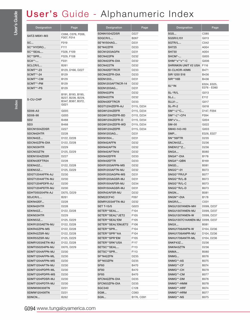
Use
r´s G
uide
www.tungaloyamerica.comG094
User’s Guide - A lphanumer ic IndexIn
dex
Designation Page
SATZ-M8X1-M3 C066, C076, F006,
F007, F014
SC... F019
SC**HYDRO... F111
SC**SEAL... F028, F109
SC**SPR... F029, F108
SCA**-... F031
SCLCR/L... B261
SCMT**-23 B129, D166, D227
SCMT**-24 B129
SCMT**-CM B129
SCMT**-PM B129
SCMT**-PS B129
S-CU-CHP
B191, B193, B195,
B227, B228, B229,
B347, B367, B372,
G021
SD06-A3 G005
SD08-98 G005
SD2 B468
SD3 B468
SDCN1504ZDSR D227
SDCN42HTR D228
SDCN42Z... D122, D228
SDCN42ZFN-DIA D122, D228
SDCN53HTR D229
SDCN53ZTN D125, D229
SDEN1504ZDSR D227
SDEN42EFTR24 D228
SDEN42Z... D122, D228
SDEN53Z... D125, D229
SDGT1204AFFN-AJ D230
SDGT1204AFTN-MJ D230
SDGT1204PDFR-AJ D230
SDGT1204PDTR-MJ D230
SDHT050204FN-AJ D070, D229
SDJCR/L... B261
SDKN42EF... D228
SDKN42HTR D228
SDKN42Z... D122, D228
SDKN53HTR D229
SDKN53Z... D125, D229
SDKR1203AETN-MJ D122, D228
SDKR42ZPN-MS D122, D228
SDKR42ZSR-MJ D122, D228
SDKR53ZSR-MJ D125, D229
SDMR1203AETN-MJ D122, D228
SDMT050204PN-MJ D070, D229
SDMT1204AFPN-MJ D230
SDMT1204AFPN-ML D230
SDMT1204AFPN-MS D230
SDMT1204AFTN-MJ D230
SDMT1204PDPR-ML D230
SDMT1204PDPR-MS D230
SDMT1204PDSR-MJ D230
SDMT1204PDTR-MJ D230
SDMW090308TN D231
SDMW120408TN D231
SDNCN... B262
Designation Page
SDNN1504ZDSR D227
SDQCR/L... B267
SE*N1504AG... D231
SE*N42ZFR D233
SECN1203AGFN D231
SECN422FN D232
SECN422FN-DIA D232
SECN422TN D232
SECN42EFTRCR D233
SECN42ZFR-DIA D233
SEEN1203... D231
SEEN1203AFTNCR-14 D232
SEEN1203AG... D231
SEEN422FN D232
SEEN422TN D232
SEEN42EFTRCR D233
SEGT12X4ZEFR-AJ D115, D234
SEGW12X4ZEFR D115, D234
SEGW12X4ZEFR-BD D115, D234
SEGW12X4ZEFR-D D115, D234
SEGW12X4ZEFR-WD D115, D234
SEGW12X4ZEPR D115, D234
SEKN1203AG... D231
SEKN1504... D231
SEKN42AFFN D232
SEKN42AFTN D232
SEKN42AFTN16 D232
SEKN42EFFR D233
SEKN42EFTR D233
SEKR1203AFPN-MS D232
SEKR1203AFTN-MJ D232
SEKR1203AGPN-MS D231
SEKR1203AGSR-MJ D231
SEKR1504AFSR-MJ D234
SEKR1504AGSR-MJ D231
SEKR42AFSR-MJ D232
SEM22CF4C F097
SEMR1203AFTN-MJ D232
SET T-15/5 G023
SETER**SEAL... F104
SETER**SEAL**JET2 F105
SETER**SEAL*EM F105
SETER**SEAL*EMJET2 F106
SETER**SPR... F104
SETER**SPR**AA F104
SETER**SPR*EM F105
SETER**SRK*USA F117
SETSC**SEAL... F113
SETSC**SPR... F113
SF*N42ZFN D235
SF*N53ZFN D235
SF60 B470
SF80 B470
SF85 B470
SFCN42ZFN-DIA D235
SFCN53ZFN-DIA D235
SGC340 C128
SGM... C083
SGN... B176, C091
Designation Page
SGS... C085
SGSR/L151 G013
SGTR/L... C042
SH725 A004
SH730 A004
SHCM*-... G005
SHM**x**x**-C G006
SHRINKIN UNIT V2 USA F116
SI-CLHOR-40M6 B471
SIR 1250 S16 B436
SIR**16B B436
SL**IN E024, E025,
E076 - E080
SL-*R/L G013
SLJ... E112
SLLV-... G017
SL-PI-2 G018
SM**-L**C... D147, F094
SM**-L**-CF4 F094
SM*×*×... G004
SM-00 G022
SM40-143-H0 G003
SMP... E026, E027
SN**56FTR D235
SNCN43Z... D236
SNEN12**Z... D236
SNGA... B080
SNGA**-DIA B178
SNGA**-QBN B169
SNGD... B081
SNGG**-01 B073
SNGG**FR/LP B077
SNGG**R/L-B B073
SNGG**R/L-C B073
SNGG**R/L-D B073
SNGN... B081
SNGN**-DIA B178
SNGR/L... C031
SNGU1307ANEN-MH D099, D237
SNGU1307ANEN-MJ D099, D237
SNGU1307ANEN-W D099, D237
SNGU1307C14ANEN-MJ D099, D237
SNGX... B081
SNHU1706ANFN-W D104, D236
SNHU1706ANPR-MJ D104, D236
SNHU1706ANTR-ML D104, D236
SNKF43Z... D236
SNKN43ZTN D236
SNMA... B080
SNMG... B076
SNMG**-AS B075
SNMG**-CF B074
SNMG**-CH B079
SNMG**-CM B077
SNMG**-DM B076
SNMG**-HMM B078
SNMG**-HRF B074
SNMG**-HRM B077
SNMG**-NS B075
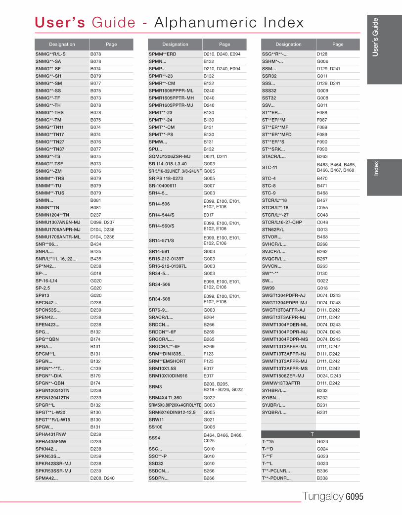
Use
r´s G
uide
Tungaloy G095
User’s Guide - A lphanumer ic Index
Ind
ex
Designation Page
SNMG**R/L-S B078
SNMG**-SA B078
SNMG**-SF B074
SNMG**-SH B079
SNMG**-SM B077
SNMG**-SS B075
SNMG**-TF B073
SNMG**-TH B078
SNMG**-THS B078
SNMG**-TM B075
SNMG**TN11 B074
SNMG**TN17 B074
SNMG**TN27 B076
SNMG**TN37 B077
SNMG**-TS B075
SNMG**-TSF B073
SNMG**-ZM B076
SNMM**-TRS B079
SNMM**-TU B079
SNMM**-TUS B079
SNMN... B081
SNMN**TN B081
SNMN1204**TN D237
SNMU1307ANEN-MJ D099, D237
SNMU1706ANPR-MJ D104, D236
SNMU1706ANTR-ML D104, D236
SNR**06... B434
SNR/L... B435
SNR/L**11, 16, 22... B435
SP*N42... D238
SP-... G018
SP-16-L14 G020
SP-2.5 G020
SP913 G020
SPCN42... D238
SPCN53S... D239
SPEN42... D238
SPEN423... D238
SPG... B132
SPG**QBN B174
SPGA... B131
SPGM**L B131
SPGN... B132
SPGN**-**T... C139
SPGN**-DIA B179
SPGN**-QBN B174
SPGN120312TN D238
SPGN120412TN D239
SPGR**L B132
SPGT**L-W20 B130
SPGT**R/L-W15 B130
SPGW... B131
SPHA431FNW D239
SPHA435FNW D239
SPKN42... D238
SPKN53S... D239
SPKR42SSR-MJ D238
SPKR53SSR-MJ D239
SPMA42... D208, D240
Designation Page
SPMM**ERD D210, D240, E094
SPMN... B132
SPMP... D210, D240, E094
SPMR**-23 B132
SPMR**-CM B132
SPMR1605PPPR-ML D240
SPMR1605PPTR-MH D240
SPMR1605PPTR-MJ D240
SPMT**-23 B130
SPMT**-24 B130
SPMT**-CM B131
SPMT**-PS B130
SPMW... B131
SPU... B132
SQMU1206ZSR-MJ D021, D241
SR 114-018-L3.40 G003
SR 5/16-32UNEF_3/8-24UNF G005
SR PS 118-0273 G005
SR-10400611 G007
SR14-5... G003
SR14-506 E099, E100, E101,
E102, E106
SR14-544/S E017
SR14-560/S E099, E100, E101,
E102, E106
SR14-571/S E099, E100, E101,
E102, E106
SR14-591 G003
SR16-212-01397 G003
SR16-212-01397L G003
SR34-5... G003
SR34-506 E099, E100, E101,
E102, E106
SR34-508 E099, E100, E101,
E102, E106
SR76-9... G003
SRACR/L... B264
SRDCN... B266
SRDCN**-6F B269
SRGCR/L... B265
SRGCR/L**-6F B269
SRM**DIN1835... F123
SRM**EMSHORT F123
SRM10X1.5S E017
SRM10X10DIN916 E017
SRM3 B203, B205,
B218 - B226, G022
SRM4X4 TL360 G022
SRM5X0.8IP20X+ACROLYTE G003
SRM6X16DIN912-12.9 G005
SRW11 G021
SS100 G006
SS94 B464, B466, B468,
C025
SSC... G010
SSC**-P G010
SSD32 G010
SSDCN... B266
SSDPN... B266
Designation Page
SSG**R**-... D128
SSHM*-... G006
SSM... D129, D241
SSR32 G011
SSS... D129, D241
SSS32 G009
SST32 G008
SSV... G011
ST**ER... F088
ST**ER**M F087
ST**ER**MF F089
ST**ER**MFD F089
ST**ER**S F090
ST**SRK... F090
STACR/L... B263
STC-11 B463, B464, B465,
B466, B467, B468
STC-4 B470
STC-8 B471
STC-9 B468
STCR/L**18 B457
STCR/L**-18 C055
STCR/L**-27 C048
STCR/L16-27-CHP C048
STN62R/L G013
STVOR... B468
SVHCR/L... B268
SVJCR/L... B262
SVQCR/L... B267
SVVCN... B263
SW**-** D130
SW... G022
SW99 G018
SWGT1304PDFR-AJ D074, D243
SWGT1304PDPR-MJ D074, D243
SWGT13T3AFFR-AJ D111, D242
SWGT13T3AFPR-MJ D111, D242
SWMT1304PDER-ML D074, D243
SWMT1304PDPR-MJ D074, D243
SWMT1304PDPR-MS D074, D243
SWMT13T3AFER-ML D111, D242
SWMT13T3AFPR-HJ D111, D242
SWMT13T3AFPR-MJ D111, D242
SWMT13T3AFPR-MS D111, D242
SWMT1506ZER-MJ D024, D243
SWMW13T3AFTR D111, D242
SYHBR/L... B232
SYIBN... B232
SYJBR/L... B231
SYQBR/L... B231
T
T-**/5 G023
T-**D G024
T-**F G023
T-**L G023
T**-PCLNR... B336
T**-PDUNR... B338
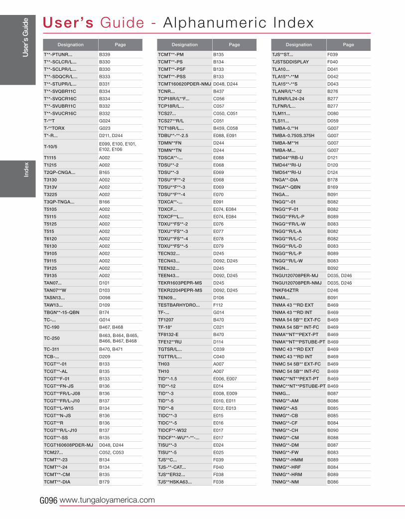
Use
r´s G
uide
www.tungaloyamerica.comG096
User’s Guide - A lphanumer ic IndexIn
dex
Designation Page
T**-PTUNR... B339
T**-SCLCR/L... B330
T**-SCLPR/L... B330
T**-SDQCR/L... B333
T**-STUPR/L... B331
T**-SVQBR11C B334
T**-SVQCR16C B334
T**-SVUBR11C B332
T**-SVUCR16C B332
T-**T G024
T-**TORX G023
T*-R... D211, D244
T-10/5 E099, E100, E101,
E102, E106
T1115 A002
T1215 A002
T2QP-CNGA... B165
T3130 A002
T313V A002
T3225 A002
T3QP-TNGA... B166
T5105 A002
T5115 A002
T5125 A002
T515 A002
T6120 A002
T6130 A002
T9105 A002
T9115 A002
T9125 A002
T9135 A002
TAN07... D101
TAN07**W D103
TASN13... D098
TAW13... D109
TBGN**-15-QBN B174
TC-... G014
TC-190 B467, B468
TC-250 B463, B464, B465,
B466, B467, B468
TC-311 B470, B471
TCB-... D209
TCGT**-01 B133
TCGT**-AL B135
TCGT**F-01 B133
TCGT**FN-JS B136
TCGT**FR/L-J08 B136
TCGT**FR/L-J10 B137
TCGT**L-W15 B134
TCGT**N-JS B136
TCGT**R B136
TCGT**R/L-J10 B137
TCGT**-SS B135
TCGT160608PDER-MJ D048, D244
TCM27... C052, C053
TCMT**-23 B134
TCMT**-24 B134
TCMT**-CM B135
TCMT**-DIA B179
Designation Page
TCMT**-PM B135
TCMT**-PS B134
TCMT**-PSF B133
TCMT**-PSS B133
TCMT160620PDER-NMJ D048, D244
TCNR... B437
TCP18R/L**F... C056
TCP18R/L... C057
TCS27... C050, C051
TCS27**R/L C051
TCT18R/L... B459, C058
TDBU**-**-2.5 E088, E091
TDMN**FN D244
TDMN**TN D244
TDSCA**-... E088
TDSU**-2 E068
TDSU**-3 E069
TDSU**F**-2 E068
TDSU**F**-3 E069
TDSU**F**-4 E070
TDXCA**-... E091
TDXCF... E074, E084
TDXCF**L... E074, E084
TDXU**FS**-2 E076
TDXU**FS**-3 E077
TDXU**FS**-4 E078
TDXU**FS**-5 E079
TECN32... D245
TECN43... D092, D245
TEEN32... D245
TEEN43... D092, D245
TEKR1603PEPR-MS D245
TEKR2204PEPR-MS D092, D245
TEN09... D106
TESTBARHYDRO... F112
TF-... G014
TF1207 B470
TF-18* C021
TF8132-E B470
TFE12**RU D114
TGTSR/L... C039
TGTTR/L... C040
TH03 A007
TH10 A007
TID**-1.5 E006, E007
TID**-12 E014
TID**-3 E008, E009
TID**-5 E010, E011
TID**-8 E012, E013
TIDC**-3 E015
TIDC**-5 E016
TIDCF**-W32 E017
TIDCF**-WU**-**-... E017
TISU**-3 E024
TISU**-5 E025
TJS**C... F039
TJS-**-CAT... F040
TJS**ER32... F038
TJS**HSKA63... F038
Designation Page
TJS**ST... F039
TJSTSDDISPLAY F040
TLA10... D041
TLA15**-**M D042
TLA15**-**S D043
TLANR/L**-12 B276
TLBNR/L24-24 B277
TLFNR/L... B277
TLM11... D080
TLS11... D059
TMBA-0.**H G007
TMBA-0.750S.375H G007
TMBA-M**H G007
TMBA-M... G007
TMD44**RB-U D121
TMD44**RI-U D120
TMD54**RI-U D124
TNGA**-DIA B178
TNGA**-QBN B169
TNGA... B091
TNGG**-01 B082
TNGG**F-01 B082
TNGG**FR/L-P B089
TNGG**FR/L-W B083
TNGG**R/L-A B082
TNGG**R/L-C B082
TNGG**R/L-D B083
TNGG**R/L-P B089
TNGG**R/L-W B083
TNGN... B092
TNGU120708PER-MJ D035, D246
TNGU120708PER-NMJ D035, D246
TNKF64ZTR D246
TNMA... B091
TNMA 43 **RD EXT B469
TNMA 43 **RD INT B469
TNMA 54 5B** EXT-FC B469
TNMA 54 5B** INT-FC B469
TNMA**NT**PEXT-PT B469
TNMA**NT**PSTUBE-PT B469
TNMC 43 **RD EXT B469
TNMC 43 **RD INT B469
TNMC 54 5B** EXT-FC B469
TNMC 54 5B** INT-FC B469
TNMC**NT**PEXT-PT B469
TNMC**NT**PSTUBE-PT B469
TNMG... B087
TNMG**-AM B086
TNMG**-AS B085
TNMG**-CB B085
TNMG**-CF B084
TNMG**-CH B090
TNMG**-CM B088
TNMG**-DM B087
TNMG**-FW B083
TNMG**-HMM B089
TNMG**-HRF B084
TNMG**-HRM B089
TNMG**-NM B086
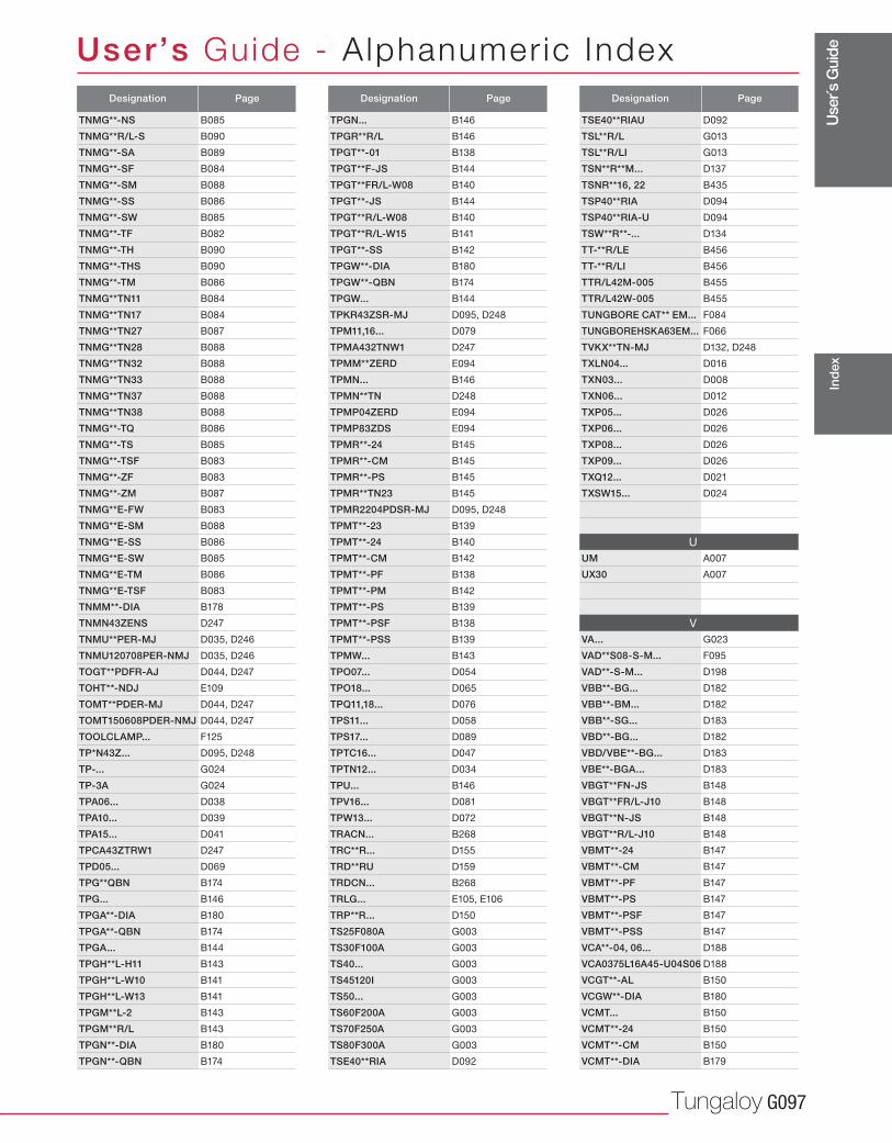
Use
r´s G
uide
Tungaloy G097
User’s Guide - A lphanumer ic Index
Ind
ex
Designation Page
TNMG**-NS B085
TNMG**R/L-S B090
TNMG**-SA B089
TNMG**-SF B084
TNMG**-SM B088
TNMG**-SS B086
TNMG**-SW B085
TNMG**-TF B082
TNMG**-TH B090
TNMG**-THS B090
TNMG**-TM B086
TNMG**TN11 B084
TNMG**TN17 B084
TNMG**TN27 B087
TNMG**TN28 B088
TNMG**TN32 B088
TNMG**TN33 B088
TNMG**TN37 B088
TNMG**TN38 B088
TNMG**-TQ B086
TNMG**-TS B085
TNMG**-TSF B083
TNMG**-ZF B083
TNMG**-ZM B087
TNMG**E-FW B083
TNMG**E-SM B088
TNMG**E-SS B086
TNMG**E-SW B085
TNMG**E-TM B086
TNMG**E-TSF B083
TNMM**-DIA B178
TNMN43ZENS D247
TNMU**PER-MJ D035, D246
TNMU120708PER-NMJ D035, D246
TOGT**PDFR-AJ D044, D247
TOHT**-NDJ E109
TOMT**PDER-MJ D044, D247
TOMT150608PDER-NMJ D044, D247
TOOLCLAMP... F125
TP*N43Z... D095, D248
TP-... G024
TP-3A G024
TPA06... D038
TPA10... D039
TPA15... D041
TPCA43ZTRW1 D247
TPD05... D069
TPG**QBN B174
TPG... B146
TPGA**-DIA B180
TPGA**-QBN B174
TPGA... B144
TPGH**L-H11 B143
TPGH**L-W10 B141
TPGH**L-W13 B141
TPGM**L-2 B143
TPGM**R/L B143
TPGN**-DIA B180
TPGN**-QBN B174
Designation Page
TPGN... B146
TPGR**R/L B146
TPGT**-01 B138
TPGT**F-JS B144
TPGT**FR/L-W08 B140
TPGT**-JS B144
TPGT**R/L-W08 B140
TPGT**R/L-W15 B141
TPGT**-SS B142
TPGW**-DIA B180
TPGW**-QBN B174
TPGW... B144
TPKR43ZSR-MJ D095, D248
TPM11,16... D079
TPMA432TNW1 D247
TPMM**ZERD E094
TPMN... B146
TPMN**TN D248
TPMP04ZERD E094
TPMP83ZDS E094
TPMR**-24 B145
TPMR**-CM B145
TPMR**-PS B145
TPMR**TN23 B145
TPMR2204PDSR-MJ D095, D248
TPMT**-23 B139
TPMT**-24 B140
TPMT**-CM B142
TPMT**-PF B138
TPMT**-PM B142
TPMT**-PS B139
TPMT**-PSF B138
TPMT**-PSS B139
TPMW... B143
TPO07... D054
TPO18... D065
TPQ11,18... D076
TPS11... D058
TPS17... D089
TPTC16... D047
TPTN12... D034
TPU... B146
TPV16... D081
TPW13... D072
TRACN... B268
TRC**R... D155
TRD**RU D159
TRDCN... B268
TRLG... E105, E106
TRP**R... D150
TS25F080A G003
TS30F100A G003
TS40... G003
TS45120I G003
TS50... G003
TS60F200A G003
TS70F250A G003
TS80F300A G003
TSE40**RIA D092
Designation Page
TSE40**RIAU D092
TSL**R/L G013
TSL**R/LI G013
TSN**R**M... D137
TSNR**16, 22 B435
TSP40**RIA D094
TSP40**RIA-U D094
TSW**R**-... D134
TT-**R/LE B456
TT-**R/LI B456
TTR/L42M-005 B455
TTR/L42W-005 B455
TUNGBORE CAT** EM... F084
TUNGBOREHSKA63EM... F066
TVKX**TN-MJ D132, D248
TXLN04... D016
TXN03... D008
TXN06... D012
TXP05... D026
TXP06... D026
TXP08... D026
TXP09... D026
TXQ12... D021
TXSW15... D024
U
UM A007
UX30 A007
V
VA... G023
VAD**S08-S-M... F095
VAD**-S-M... D198
VBB**-BG... D182
VBB**-BM... D182
VBB**-SG... D183
VBD**-BG... D182
VBD/VBE**-BG... D183
VBE**-BGA... D183
VBGT**FN-JS B148
VBGT**FR/L-J10 B148
VBGT**N-JS B148
VBGT**R/L-J10 B148
VBMT**-24 B147
VBMT**-CM B147
VBMT**-PF B147
VBMT**-PS B147
VBMT**-PSF B147
VBMT**-PSS B147
VCA**-04, 06... D188
VCA0375L16A45-U04S06 D188
VCGT**-AL B150
VCGW**-DIA B180
VCMT... B150
VCMT**-24 B150
VCMT**-CM B150
VCMT**-DIA B179
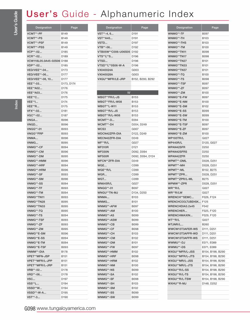
Use
r´s G
uide
www.tungaloyamerica.comG098
User’s Guide - A lphanumer ic IndexIn
dex
Designation Page
VCMT**-PF B149
VCMT**-PS B149
VCMT**-PSF B149
VCMT**-PSS B149
VCP**-02... D185
VCR**-02... D189
VCW118L05.0A45-02S06 D188
VDP**-02... D185
VED/VEE**-04... D173
VED/VEE**-06... D177
VED/VEE**-08, 10... D177
VEE**-03... D173, D174
VEE**A02... D176
VEE**A03... D176
VEE**C... D175
VEE**I... D174
VEE**R... D175
VFX**-02... D181
VGC**-02... D187
VNGA... B096
VNGD... B096
VNGG**-01 B093
VNGG**FRP B093
VNMA... B096
VNMG... B095
VNMG**-CF B094
VNMG**-CM B096
VNMG**-DM B095
VNMG**-HMM B096
VNMG**-HRF B094
VNMG**-HRM B096
VNMG**-SF B093
VNMG**-SM B096
VNMG**-SS B094
VNMG**-TF B093
VNMG**-TM B094
VNMG**TN11 B093
VNMG**TN28 B095
VNMG**TN33 B095
VNMG**-TQ B095
VNMG**-TS B094
VNMG**-TSF B093
VNMG**-ZF B093
VNMG**-ZM B095
VNMG**E-SM B096
VNMG**E-SS B094
VNMG**E-TM B094
VNMG**E-TSF B093
VNMM**-DIA B178
VPET**MFN-JSP B151
VPET**MFR/L-JPP B151
VPET**MFR/L-JRP B151
VRB**-02... D178
VRD**-06... D178
VSC... D197
VSS**L... D194
VSSD**W... D194
VSSD**-W-A... D195
VST**-3... D190
Designation Page
VST**-4, 6... D191
VST**A45... D191
VSTD... D197
VTB**-06... D192
VTB05W**C006-U06S05 D192
VTS**L**S... D196
VTSD... D196
VTSD**L**0S06-W-A D196
VX040024A G003
VX040028A G003
VXGU**MFR/LE-JRP B152, B200, B292
W
WBGT**FR/L-JS B153
WBGT**FR/L-W08 B153
WBGT**L-W11 B153
WBGT**R/L-JS B153
WBGT**R/L-W08 B153
WCMT**-D... E094
WCMT**-D4 D204, D249
WCS3 G007
WDCN42ZFR-DIA D122, D249
WECN42ZFR-DIA D249
WF**R/L G027
WF310R D121
WF330N D092, D094
WF500R D092, D094, D124
WFCN**ZFR-DIA D249
WGE... C099
WGE**R/L C099
WGR... C099
WGT... C099
WN645R/L G027
WNGG**-01 B097
WNGU**TN-MJ D134, D250
WNMA... B103
WNMG... B101
WNMG**-AFW B097
WNMG**-AM B100
WNMG**-AS B099
WNMG**-ASW B099
WNMG**-CB B099
WNMG**-CF B098
WNMG**-CH B103
WNMG**-CM B102
WNMG**-DM B101
WNMG**-FW B097
WNMG**-HMM B102
WNMG**-HRF B098
WNMG**-HRM B102
WNMG**-NM B100
WNMG**-NS B099
WNMG**-SA B102
WNMG**-SF B098
WNMG**-SH B103
WNMG**-SM B102
WNMG**-SS B099
WNMG**-SW B099
Designation Page
WNMG**-TF B097
WNMG**-TH B103
WNMG**-THS B103
WNMG**-TM B100
WNMG**TN11 B098
WNMG**TN17 B098
WNMG**TN27 B101
WNMG**TN33 B101
WNMG**TN37 B101
WNMG**-TQ B100
WNMG**-TS B098
WNMG**-TSF B097
WNMG**-ZF B097
WNMG**-ZM B100
WNMG**E-FW B097
WNMG**E-NM B100
WNMG**E-SM B102
WNMG**E-SS B099
WNMG**E-SW B099
WNMG**E-TM B100
WNMG**E-TSF B097
WNMG**E-ZF B097
WNMG**E-ZM B100
WP193TR/L G027
WP440R/L D120, G027
WPAN42SFR D250
WPAN42SFRS D250
WPAN42ZFR D250
WPMT**-DML D028, D251
WPMT**-MH D028, D251
WPMT**-ML B152, B275
WPMT**ZPR... D028, D251
WPMT**ZPR/L-ML B275
WPMW**-ZPR D028, D251
WR**R/L G027
WR**R/LW G027
WRENCH**SEMC... F026, F124
WRENCHCOOLTUBEHSK... F125
WRENCHDIA3.2x45 F042
WRENCHER... F025, F120
WRENCHMAXIN... F029, F120
WT**R/L G027
WTJNR/L... B260
WWCW13T3AFER-WS D111, D251
WWCW13T3AFFR-WD D111, D251
WWCW13T3AFFR-WS D111, D251
WWMU**-DJ E071, E089
WWMU**-DS E071, E089
WXGU**MFR/L-JSS B154, B198, B290
WXGU**MFR/L-JTS B154, B198, B290
WXGU**MR/L-JSS B154, B198, B290
WXGU**MR/L-JTS B154, B198, B290
WXGU**R/L-SS B154, B198, B290
WXGU**R/L-TS B154, B198, B290
WXGU**R/L-TSW B154, B198, B290
WXHU**R-MJ D148, D252
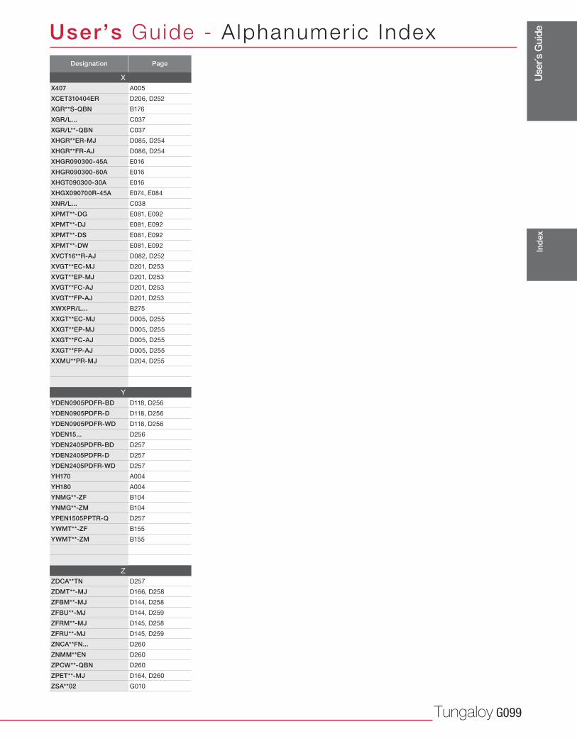
Use
r´s G
uide
Tungaloy G099
User’s Guide - A lphanumer ic Index
Ind
ex
Designation Page
X
X407 A005
XCET310404ER D206, D252
XGR**S-QBN B176
XGR/L... C037
XGR/L**-QBN C037
XHGR**ER-MJ D085, D254
XHGR**FR-AJ D086, D254
XHGR090300-45A E016
XHGR090300-60A E016
XHGT090300-30A E016
XHGX090700R-45A E074, E084
XNR/L... C038
XPMT**-DG E081, E092
XPMT**-DJ E081, E092
XPMT**-DS E081, E092
XPMT**-DW E081, E092
XVCT16**R-AJ D082, D252
XVGT**EC-MJ D201, D253
XVGT**EP-MJ D201, D253
XVGT**FC-AJ D201, D253
XVGT**FP-AJ D201, D253
XWXPR/L... B275
XXGT**EC-MJ D005, D255
XXGT**EP-MJ D005, D255
XXGT**FC-AJ D005, D255
XXGT**FP-AJ D005, D255
XXMU**PR-MJ D204, D255
Y
YDEN0905PDFR-BD D118, D256
YDEN0905PDFR-D D118, D256
YDEN0905PDFR-WD D118, D256
YDEN15... D256
YDEN2405PDFR-BD D257
YDEN2405PDFR-D D257
YDEN2405PDFR-WD D257
YH170 A004
YH180 A004
YNMG**-ZF B104
YNMG**-ZM B104
YPEN1505PPTR-Q D257
YWMT**-ZF B155
YWMT**-ZM B155
Z
ZDCA**TN D257
ZDMT**-MJ D166, D258
ZFBM**-MJ D144, D258
ZFBU**-MJ D144, D259
ZFRM**-MJ D145, D258
ZFRU**-MJ D145, D259
ZNCA**FN... D260
ZNMM**EN D260
ZPCW**-QBN D260
ZPET**-MJ D164, D260
ZSA**02 G010

MEMO

MEMO

MEMO

MEMO

MEMO

MEMO

MEMO

MEMO