Embed Size (px)
Citation preview
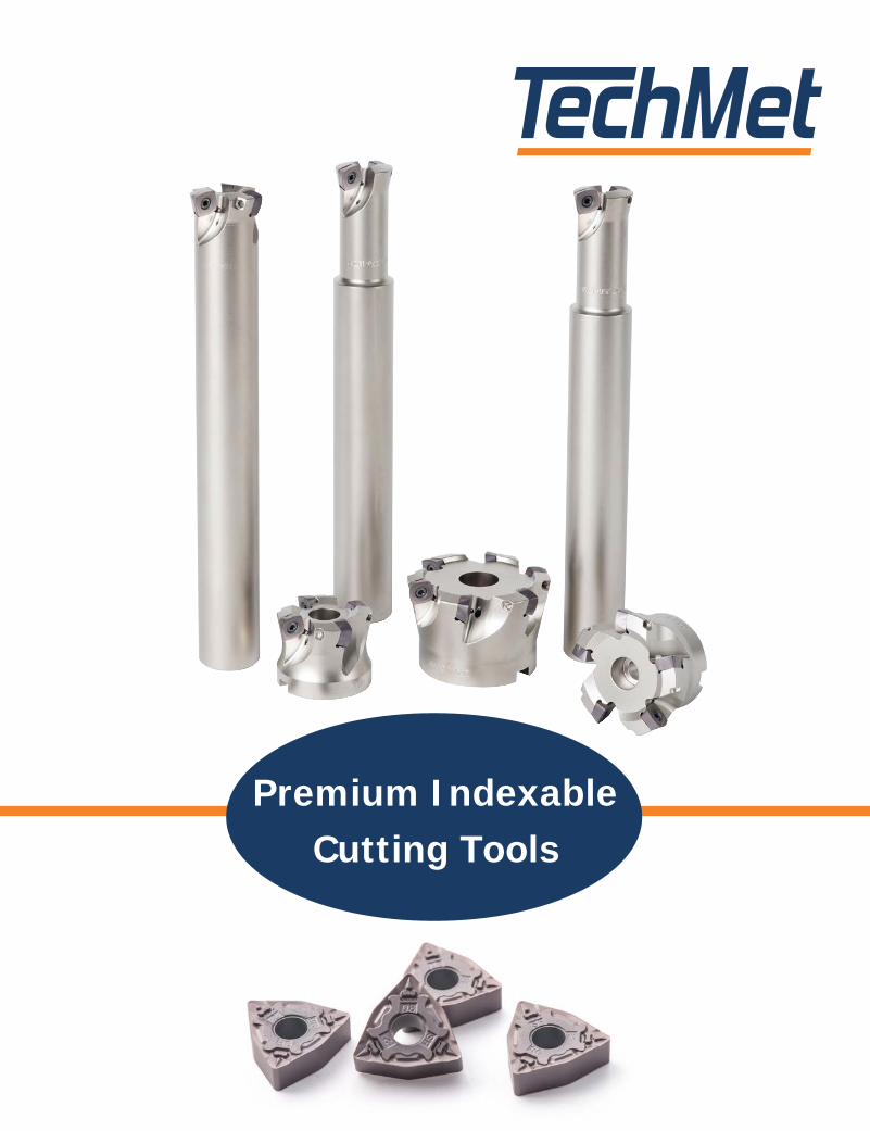
Premium IndexableCutting Tools

North America’s #1 Supplier of Carbide Tool BlanksSince 1998 TechMet Carbides has supplied premium carbide tool blanks for production
of high performance cutting tools throughout North America. Our extensive range of
carbides are used by leading manufacturers to produce all types of solid carbide endmills
and drills, carbide burrs, carbide-tipped saws and custom carbide inserts.
Our dedication to Quality, Performance and Value has made us the #1 Supplier of
performance Carbide Tool Blanks in North America. Our carbide has been used for
hundreds of millions of cutting tools – tools that are already in your shop, running on
your machines.
TechMet Premium Indexable ToolingTechMet has now brought our extensive carbide knowledge and experience to
indexable cutting tools. We are proud to introduce an optimized range of advanced
insert technology - incorporating premium carbide substrates and advanced geometry
chipbreaker designs with custom performance coatings. We offer a full range of indexable
insert solutions to give metalcutting shops a strong competitive advantage. TechMet’s
bedrock principles of Quality, Performance and Value are built into every tool.
The TechMet Commitment to metalworking professionals will always be
PP Premium Performance with Consistent Quality
PP Outstanding Service and Support
PP Inventory Security with Same-Day Shipping
PP The Best Value for Your Production
NEW!
2 877.872.0044 www.techmet-carbide.com
33
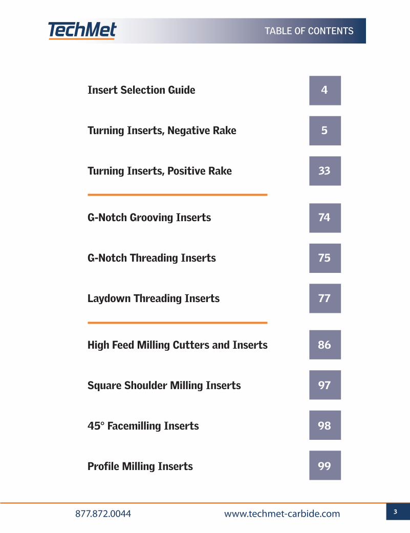
Insert Selection Guide 4
Turning Inserts, Negative Rake 5
Turning Inserts, Positive Rake 33
G-Notch Grooving Inserts 74
G-Notch Threading Inserts 75
Laydown Threading Inserts 77
High Feed Milling Cutters and Inserts 86
Square Shoulder Milling Inserts 97
45° Facemilling Inserts 98
Profile Milling Inserts 99
TABLE OF CONTENTS
877.872.0044 www.techmet-carbide.com
4 877.872.0044 www.techmet-carbide.com
INSERT SELECTION GUIDE
Insert Shape Application Conditions (+) Considerations (-)
S - Square
• Very strong 90o corner with excellent economy (8 edges on double-sided inserts).
• Most often used for rough facing operations – especially on castings, forgings and rough-sawed blanks.
• Unable to turn or face up to a shoulder (must be used in a toolholder with minimum 5o lead angle).
• High radial forces push against the workpiece when used for turning.
• Should always be used in a stable set-up.
C - 80o Diamond
• The most popular insert shape due to high versatility.
• Strong cutting edge with secure seating in the insert pocket.
• 80o corner can be used for both turning and facing operations.
• Opposite 100o corners can be used for general roughing applications (especially facing), providing maximum economy of 8 total cutting edges.
• With only 5o of clearance between the trailing side of the insert and the workpiece, chip jamming can occur when boring.
W - 80o Corner Trigon
• Six-corner 80o diamond shape that can increase economy compared to CNMG-style inserts.
• Generally used on more moderate depths of cut and feedrates than CNMG-style inserts.
• Seating of insert in pocket is not as stable as CNMG-style inserts.
• Cannot take as deep a depth of cut as similar sized CNMG-type inserts.
T - Triangle
• Very versatile insert shape – can be used for turning, facing, boring, copy turning and basic profiling.
• Good economy with up to 6 cutting edges.
• Excellent choice for general boring due to very stable seating of the insert in the boring bar pocket, and extra side clearance between the insert and the workpiece bore (greatly reducing the risk of chip jamming).
• Edge is measurably weaker than 80o diamond shaped inserts.
• Be sure not to use a triangle insert that is “too large” for the application, as the cost per edge can increase. For example, a 3/8” iC (Inscribed Circle) triangle insert (TNMG-33x) can manage up to .375” depth of cut in most situations with nearly the same insert strength – but a much lower cost - than a 1/2” iC triangle insert (TNMG-43x).
D - 55o Diamond
• Generally the first choice for profile / copy turning applications.
• Able to ”In-Copy” (plunge turn into a smaller diameter) at an angle of 30o.
• Commonly used when machining close to the tailstock / live center.
• Somewhat weaker edge strength than a triangle insert.
• Cost per edge is higher than most other turning inserts (except 35o diamond shape).
V - 35o Diamond
• First choice for intricate shape copy turning.
• Can ”In-Copy” (plunge turn into a smaller diameter) at an angle up to 49o.
• Can work extremely close to the tailstock / live center.
• The weakest turning insert shape / corner – depths of cut and feedrates must be lighter.
• Highest cost per edge.
• Negative style (VNMG) should mainly be used for external applications.
• Positive style (VCMT) can be used for external and internal applications, and in many cases improved performance outweighs the increased cost per edge (2 edges vs. the 4 edges of a negative 35o diamond VNMG).
90o
80o
80o
60o
55o
35o
TURNING INSERTS | NEGATIVE RAKEANSI / ISO STANDARD INSERTS
FOR MOST EXTERNAL TURNING AND
INTERNAL MACHINING OPERATIONS

6 877.872.0044 www.techmet-carbide.com
See pages 68 and 69 for more information on grades for turning.
C4 01
C3 10
C2 20
C1 30
– 01
– 10
– 20
– 30
GRADES | NEGATIVE RAKE INSERTS
WORKPIECEMATERIAL
ANSI ISOCoating Type
CVD PVD
C8 01
10
20
30
40
GP1
115
GP1
225 P
Steel
toug
hnes
s w
ear
resi
stan
ce
– 01
– 10
– 20
– 30
GM
1125
GM
3125
MStainless
Steel
toug
hnes
s w
ear
resi
stan
ce
KCast Iron
GK
1115
GK
1125
toug
hnes
s w
ear
resi
stan
ce
C7
C6
GP1
135
GS3
115
SHeat-ResistantSuper Alloys
toug
hnes
s w
ear
resi
stan
ce
GS3
115
GP1
105
7 877.872.0044 www.techmet-carbide.com
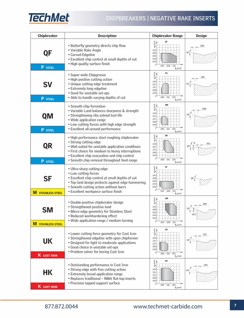
CHIPBREAKERS | NEGATIVE RAKE INSERTS
Chipbreaker Description Chipbreaker Range Design
• Butterfly geometry directs chip flow• Variable Rake Angle• Curved Edgeline• Excellent chip control at small depths of cut • High quality surface finish
QF
P STEEL
• Super-wide Chipgroove• High positive cutting action• Unique cutting edge treatment• Extremely long edgeline• Good for unstable set-ups• Able to handle varying depths of cut
SV
P STEEL
• Smooth chip formation• Variable Land balances sharpness & strength• Strengthening ribs extend tool life• Wide application range• Low cutting forces with high edge strength• Excellent all-around performance
QM
P STEEL
QR
P STEEL
• High performance steel roughing chipbreaker• Strong cutting edge• Well suited for unstable application conditions• First choice for medium to heavy interruptions• Excellent chip evacuation and chip control• Smooth chip removal throughout feed range
SF
M STAINLESS STEEL
• Ultra-sharp cutting edge• Low cutting forces• Excellent chip control at small depths of cut• Top land design protects against edge hammering• Smooth cutting action without burrs• Excellent workpiece surface finish
• Double-positive chipbreaker design• Strengthened positive land• Micro-edge geometry for Stainless Steel• Reduced workhardening effect• Wide application range / medium turning
SM
M STAINLESS STEEL
• Lower cutting force geometry for Cast Iron• Strengthened edgeline with open chipformer• Designed for light to moderate applications• Good choice in unstable set-ups• Problem solver for boring Cast Iron
UK
K CAST IRON
• Outstanding performance in Cast Iron• Strong edge with free cutting action• Extremely broad application range• Replaces traditional – NMA flat-top inserts• Precision lapped support surface
HK
K CAST IRON
SM
.004 .008 .012 fn (inch)
.100
.080
.060
.040
.020
0
a p (i
nch)
UK
.008 .016 .024 fn (inch)
.200
.156
.125
.080
.040
0
a p (i
nch)
HK
.008 .016 .024 fn (inch)
.200
.156
.125
.080
.040
0
a p (i
nch)
QM
.008 .016 .024 fn (inch)
.200
.156
.125
.080
.040
0
a p (i
nch)
SV
.008 .016 .024 fn (inch)
.200
.156
.125
.080
.040
0
a p (i
nch)
QF
.004 .008 .012 fn (inch)
.100
.080
.060
.040
.020
0
a p (i
nch)
.026 .005
.008
25o 15o
12o
7o
.005
8o
19o
19o
5o or 7o
.005
8o
19o
11o
15.5o
.003
23o
.007
15o
.012
16o
.015
24o
.026 .005
.008
25o 15o
12o
7o
.005
8o
19o
19o
5o or 7o
.005
8o
19o
11o
15.5o
.003
23o
.007
15o
.012
16o
.015
24o .026 .005
.008
25o 15o
12o
7o
.005
8o
19o
19o
5o or 7o
.005
8o
19o
11o
15.5o
.003
23o
.007
15o
.012
16o
.015
24o
.026 .005
.008
25o 15o
12o
7o
.005
8o
19o
19o
5o or 7o
.005
8o
19o
11o
15.5o
.003
23o
.007
15o
.012
16o
.015
24o
.026 .005
.008
25o 15o
12o
7o
.005
8o
19o
19o
5o or 7o
.005
8o
19o
11o
15.5o
.003
23o
.007
15o
.012
16o
.015
24o
.026 .005
.008
25o 15o
12o
7o
.005
8o
19o
19o
5o or 7o
.005
8o
19o
11o
15.5o
.003
23o
.007
15o
.012
16o
.015
24o
SF
.004 .008 .012 fn (inch)
.100
.080
.060
.040
.020
0
a p (i
nch)
QR
.008 .016 .024 fn (inch)
.200
.156
.125
.080
.040
0
a p (i
nch)
18o
.01220o
3o
REFERENCE PAGES
GRADE SELECTION GUIDE 6 TECHNICAL INFORMATION 59 CUTTING SPEED RECOMMENDATIONS 66
8 877.872.0044 www.techmet-carbide.com
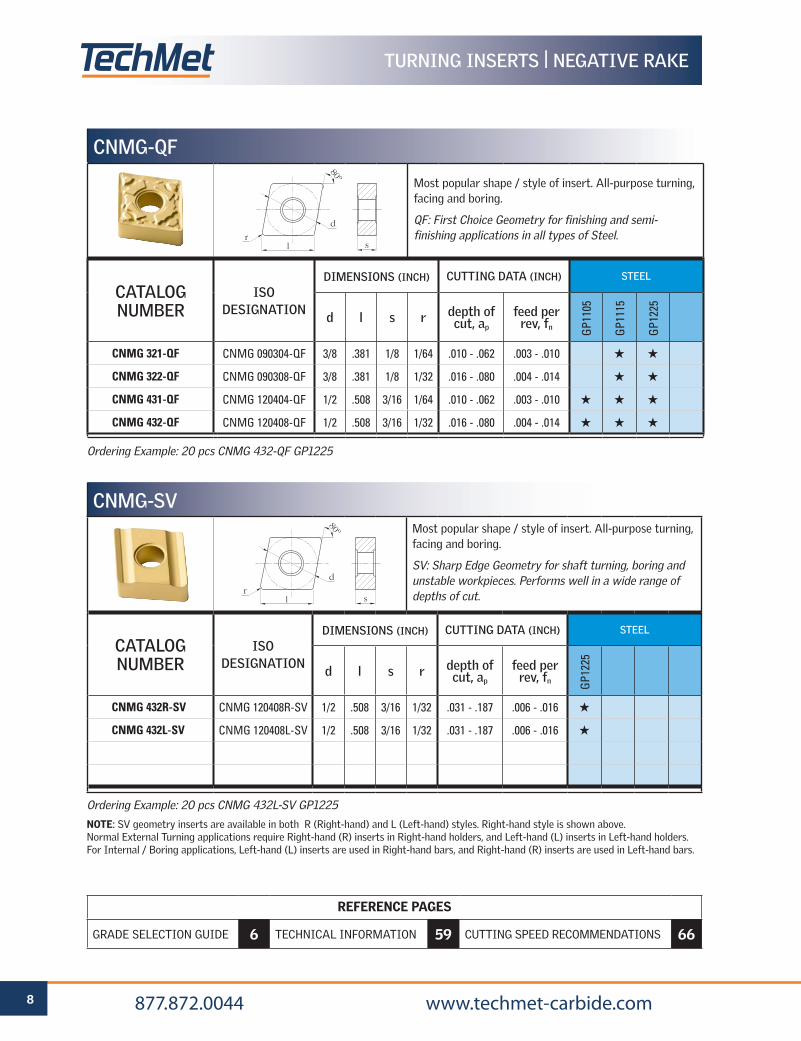
Ordering Example: 20 pcs CNMG 432-QF GP1225
Ordering Example: 20 pcs CNMG 432L-SV GP1225
NOTE: SV geometry inserts are available in both R (Right-hand) and L (Left-hand) styles. Right-hand style is shown above. Normal External Turning applications require Right-hand (R) inserts in Right-hand holders, and Left-hand (L) inserts in Left-hand holders. For Internal / Boring applications, Left-hand (L) inserts are used in Right-hand bars, and Right-hand (R) inserts are used in Left-hand bars.
CNMG-SVMost popular shape / style of insert. All-purpose turning, facing and boring.
SV: Sharp Edge Geometry for shaft turning, boring and unstable workpieces. Performs well in a wide range of depths of cut.
CATALOG NUMBER
ISO DESIGNATION
DIMENSIONS (INCH) CUTTING DATA (INCH) STEEL
d l s r depth of cut, ap
feed per rev, fn G
P122
5
CNMG 432R-SV CNMG 120408R-SV 1/2 .508 3/16 1/32 .031 - .187 .006 - .016 H
CNMG 432L-SV CNMG 120408L-SV 1/2 .508 3/16 1/32 .031 - .187 .006 - .016 H
d
l sr
80º
TURNING INSERTS | NEGATIVE RAKE
CNMG-QF
Most popular shape / style of insert. All-purpose turning, facing and boring.
QF: First Choice Geometry for finishing and semi-finishing applications in all types of Steel.
CATALOG NUMBER
ISO DESIGNATION
DIMENSIONS (INCH) CUTTING DATA (INCH) STEEL
d l s r depth of cut, ap
feed per rev, fn G
P110
5
GP1
115
GP1
225
CNMG 321-QF CNMG 090304-QF 3/8 .381 1/8 1/64 .010 - .062 .003 - .010 H H
CNMG 322-QF CNMG 090308-QF 3/8 .381 1/8 1/32 .016 - .080 .004 - .014 H H
CNMG 431-QF CNMG 120404-QF 1/2 .508 3/16 1/64 .010 - .062 .003 - .010 H H H
CNMG 432-QF CNMG 120408-QF 1/2 .508 3/16 1/32 .016 - .080 .004 - .014 H H H
d
l sr
80º
REFERENCE PAGES
GRADE SELECTION GUIDE 6 TECHNICAL INFORMATION 59 CUTTING SPEED RECOMMENDATIONS 66
9 877.872.0044 www.techmet-carbide.com
TURNING INSERTS | NEGATIVE RAKE
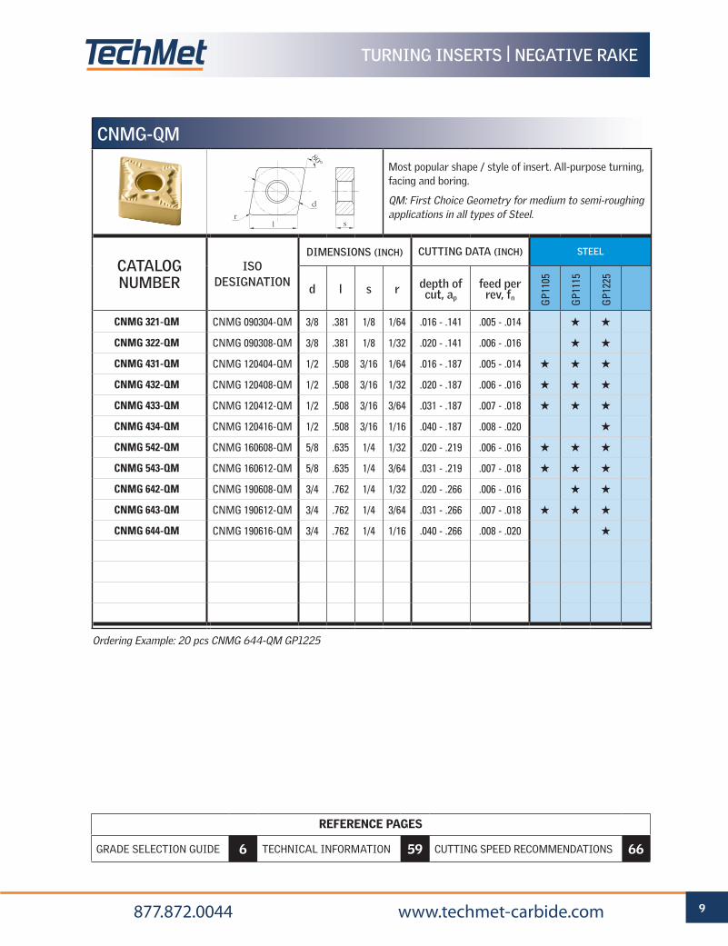
Ordering Example: 20 pcs CNMG 644-QM GP1225
CNMG-QM
Most popular shape / style of insert. All-purpose turning, facing and boring.
QM: First Choice Geometry for medium to semi-roughing applications in all types of Steel.
CATALOG NUMBER
ISO DESIGNATION
DIMENSIONS (INCH) CUTTING DATA (INCH) STEEL
d l s r depth of cut, ap
feed per rev, fn G
P110
5
GP1
115
GP1
225
CNMG 321-QM CNMG 090304-QM 3/8 .381 1/8 1/64 .016 - .141 .005 - .014 H H
CNMG 322-QM CNMG 090308-QM 3/8 .381 1/8 1/32 .020 - .141 .006 - .016 H H
CNMG 431-QM CNMG 120404-QM 1/2 .508 3/16 1/64 .016 - .187 .005 - .014 H H H
CNMG 432-QM CNMG 120408-QM 1/2 .508 3/16 1/32 .020 - .187 .006 - .016 H H H
CNMG 433-QM CNMG 120412-QM 1/2 .508 3/16 3/64 .031 - .187 .007 - .018 H H H
CNMG 434-QM CNMG 120416-QM 1/2 .508 3/16 1/16 .040 - .187 .008 - .020 H
CNMG 542-QM CNMG 160608-QM 5/8 .635 1/4 1/32 .020 - .219 .006 - .016 H H H
CNMG 543-QM CNMG 160612-QM 5/8 .635 1/4 3/64 .031 - .219 .007 - .018 H H H
CNMG 642-QM CNMG 190608-QM 3/4 .762 1/4 1/32 .020 - .266 .006 - .016 H H
CNMG 643-QM CNMG 190612-QM 3/4 .762 1/4 3/64 .031 - .266 .007 - .018 H H H
CNMG 644-QM CNMG 190616-QM 3/4 .762 1/4 1/16 .040 - .266 .008 - .020 H
d
l sr
80º
REFERENCE PAGES
GRADE SELECTION GUIDE 6 TECHNICAL INFORMATION 59 CUTTING SPEED RECOMMENDATIONS 66
10 877.872.0044 www.techmet-carbide.com
TURNING INSERTS | NEGATIVE RAKE
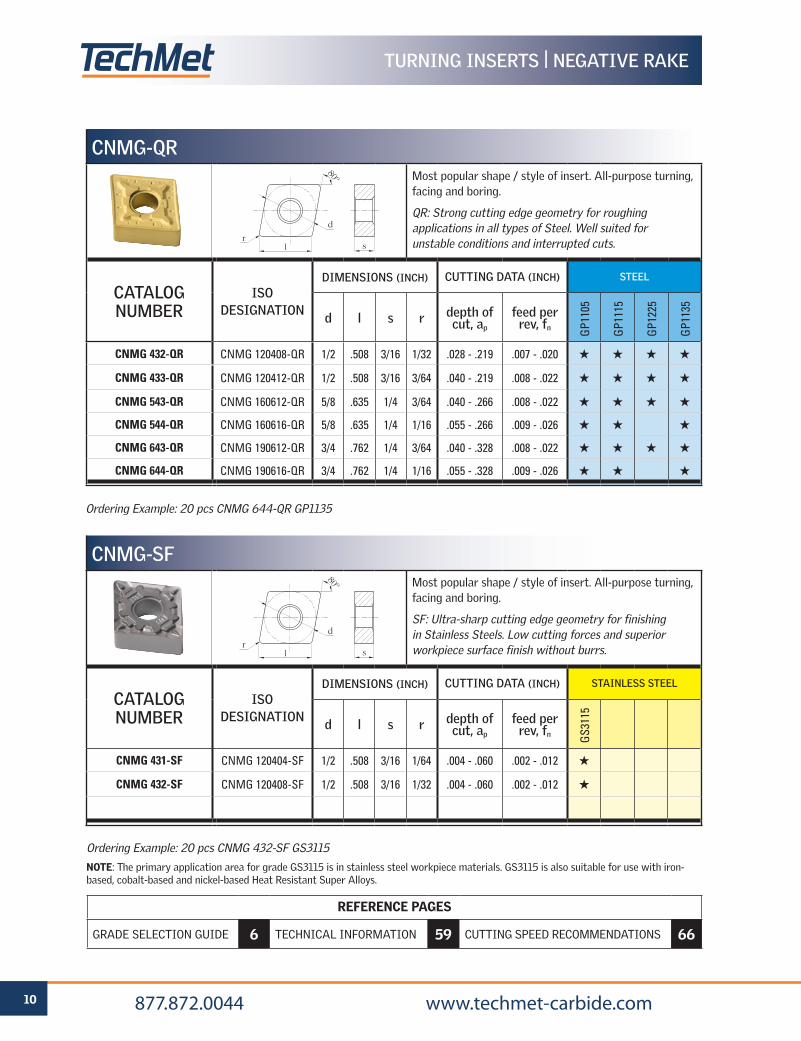
Ordering Example: 20 pcs CNMG 432-SF GS3115
NOTE: The primary application area for grade GS3115 is in stainless steel workpiece materials. GS3115 is also suitable for use with iron-based, cobalt-based and nickel-based Heat Resistant Super Alloys.
CNMG-SFMost popular shape / style of insert. All-purpose turning, facing and boring.
SF: Ultra-sharp cutting edge geometry for finishing in Stainless Steels. Low cutting forces and superior workpiece surface finish without burrs.
CATALOG NUMBER
ISO DESIGNATION
DIMENSIONS (INCH) CUTTING DATA (INCH) STAINLESS STEEL
d l s r depth of cut, ap
feed per rev, fn G
S311
5
CNMG 431-SF CNMG 120404-SF 1/2 .508 3/16 1/64 .004 - .060 .002 - .012 H
CNMG 432-SF CNMG 120408-SF 1/2 .508 3/16 1/32 .004 - .060 .002 - .012 H
d
l sr
80º
Ordering Example: 20 pcs CNMG 644-QR GP1135
CNMG-QRMost popular shape / style of insert. All-purpose turning, facing and boring.
QR: Strong cutting edge geometry for roughing applications in all types of Steel. Well suited for unstable conditions and interrupted cuts.
CATALOG NUMBER
ISO DESIGNATION
DIMENSIONS (INCH) CUTTING DATA (INCH) STEEL
d l s r depth of cut, ap
feed per rev, fn G
P110
5
GP1
115
GP1
225
GP1
135
CNMG 432-QR CNMG 120408-QR 1/2 .508 3/16 1/32 .028 - .219 .007 - .020 H H H H
CNMG 433-QR CNMG 120412-QR 1/2 .508 3/16 3/64 .040 - .219 .008 - .022 H H H H
CNMG 543-QR CNMG 160612-QR 5/8 .635 1/4 3/64 .040 - .266 .008 - .022 H H H H
CNMG 544-QR CNMG 160616-QR 5/8 .635 1/4 1/16 .055 - .266 .009 - .026 H H H
CNMG 643-QR CNMG 190612-QR 3/4 .762 1/4 3/64 .040 - .328 .008 - .022 H H H H
CNMG 644-QR CNMG 190616-QR 3/4 .762 1/4 1/16 .055 - .328 .009 - .026 H H H
d
l sr
80º
REFERENCE PAGES
GRADE SELECTION GUIDE 6 TECHNICAL INFORMATION 59 CUTTING SPEED RECOMMENDATIONS 66
11 877.872.0044 www.techmet-carbide.com
TURNING INSERTS | NEGATIVE RAKE
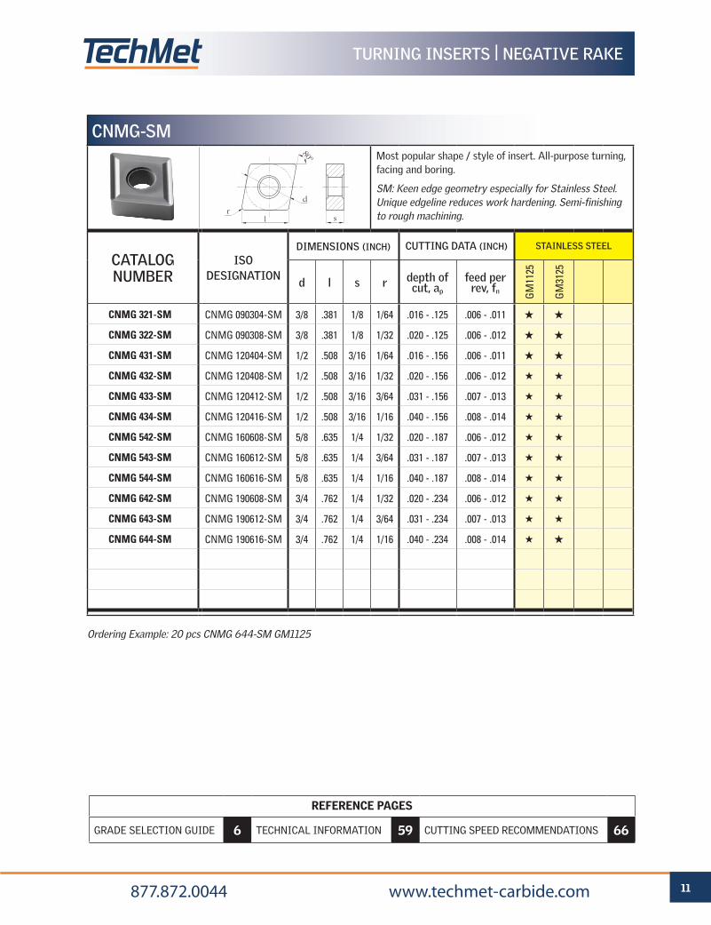
Ordering Example: 20 pcs CNMG 644-SM GM1125
CNMG-SMMost popular shape / style of insert. All-purpose turning, facing and boring.
SM: Keen edge geometry especially for Stainless Steel. Unique edgeline reduces work hardening. Semi-finishing to rough machining.
CATALOG NUMBER
ISO DESIGNATION
DIMENSIONS (INCH) CUTTING DATA (INCH) STAINLESS STEEL
d l s r depth of cut, ap
feed per rev, fn G
M11
25
GM
3125
CNMG 321-SM CNMG 090304-SM 3/8 .381 1/8 1/64 .016 - .125 .006 - .011 H H
CNMG 322-SM CNMG 090308-SM 3/8 .381 1/8 1/32 .020 - .125 .006 - .012 H H
CNMG 431-SM CNMG 120404-SM 1/2 .508 3/16 1/64 .016 - .156 .006 - .011 H H
CNMG 432-SM CNMG 120408-SM 1/2 .508 3/16 1/32 .020 - .156 .006 - .012 H H
CNMG 433-SM CNMG 120412-SM 1/2 .508 3/16 3/64 .031 - .156 .007 - .013 H H
CNMG 434-SM CNMG 120416-SM 1/2 .508 3/16 1/16 .040 - .156 .008 - .014 H H
CNMG 542-SM CNMG 160608-SM 5/8 .635 1/4 1/32 .020 - .187 .006 - .012 H H
CNMG 543-SM CNMG 160612-SM 5/8 .635 1/4 3/64 .031 - .187 .007 - .013 H H
CNMG 544-SM CNMG 160616-SM 5/8 .635 1/4 1/16 .040 - .187 .008 - .014 H H
CNMG 642-SM CNMG 190608-SM 3/4 .762 1/4 1/32 .020 - .234 .006 - .012 H H
CNMG 643-SM CNMG 190612-SM 3/4 .762 1/4 3/64 .031 - .234 .007 - .013 H H
CNMG 644-SM CNMG 190616-SM 3/4 .762 1/4 1/16 .040 - .234 .008 - .014 H H
d
l sr
80º
REFERENCE PAGES
GRADE SELECTION GUIDE 6 TECHNICAL INFORMATION 59 CUTTING SPEED RECOMMENDATIONS 66
12 877.872.0044 www.techmet-carbide.com
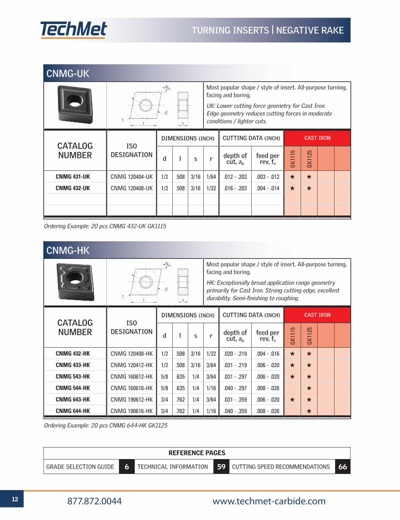
Ordering Example: 20 pcs CNMG 644-HK GK1125
CNMG-HKMost popular shape / style of insert. All-purpose turning, facing and boring.
HK: Exceptionally broad application range geometry primarily for Cast Iron. Strong cutting edge, excellent durability. Semi-finishing to roughing.
CATALOG NUMBER
ISO DESIGNATION
DIMENSIONS (INCH) CUTTING DATA (INCH) CAST IRON
d l s r depth of cut, ap
feed per rev, fn G
K111
5
GK1
125
CNMG 432-HK CNMG 120408-HK 1/2 .508 3/16 1/32 .020 - .219 .004 - .016 H H
CNMG 433-HK CNMG 120412-HK 1/2 .508 3/16 3/64 .031 - .219 .006 - .020 H H
CNMG 543-HK CNMG 160612-HK 5/8 .635 1/4 3/64 .031 - .297 .006 - .020 H H
CNMG 544-HK CNMG 160616-HK 5/8 .635 1/4 1/16 .040 - .297 .008 - .026 H
CNMG 643-HK CNMG 190612-HK 3/4 .762 1/4 3/64 .031 - .359 .006 - .020 H H
CNMG 644-HK CNMG 190616-HK 3/4 .762 1/4 1/16 .040 - .359 .008 - .026 H
Ordering Example: 20 pcs CNMG 432-UK GK1115
CNMG-UKMost popular shape / style of insert. All-purpose turning, facing and boring.
UK: Lower cutting force geometry for Cast Iron. Edge geometry reduces cutting forces in moderate conditions / lighter cuts.
CATALOG NUMBER
ISO DESIGNATION
DIMENSIONS (INCH) CUTTING DATA (INCH) CAST IRON
d l s r depth of cut, ap
feed per rev, fn G
K111
5
GK1
125
CNMG 431-UK CNMG 120404-UK 1/2 .508 3/16 1/64 .012 - .203 .003 - .012 H H
CNMG 432-UK CNMG 120408-UK 1/2 .508 3/16 1/32 .016 - .203 .004 - .014 H H
d
l sr
80º
d
l sr
80º
TURNING INSERTS | NEGATIVE RAKE
REFERENCE PAGES
GRADE SELECTION GUIDE 6 TECHNICAL INFORMATION 59 CUTTING SPEED RECOMMENDATIONS 66
13 877.872.0044 www.techmet-carbide.com
TURNING INSERTS | NEGATIVE RAKE
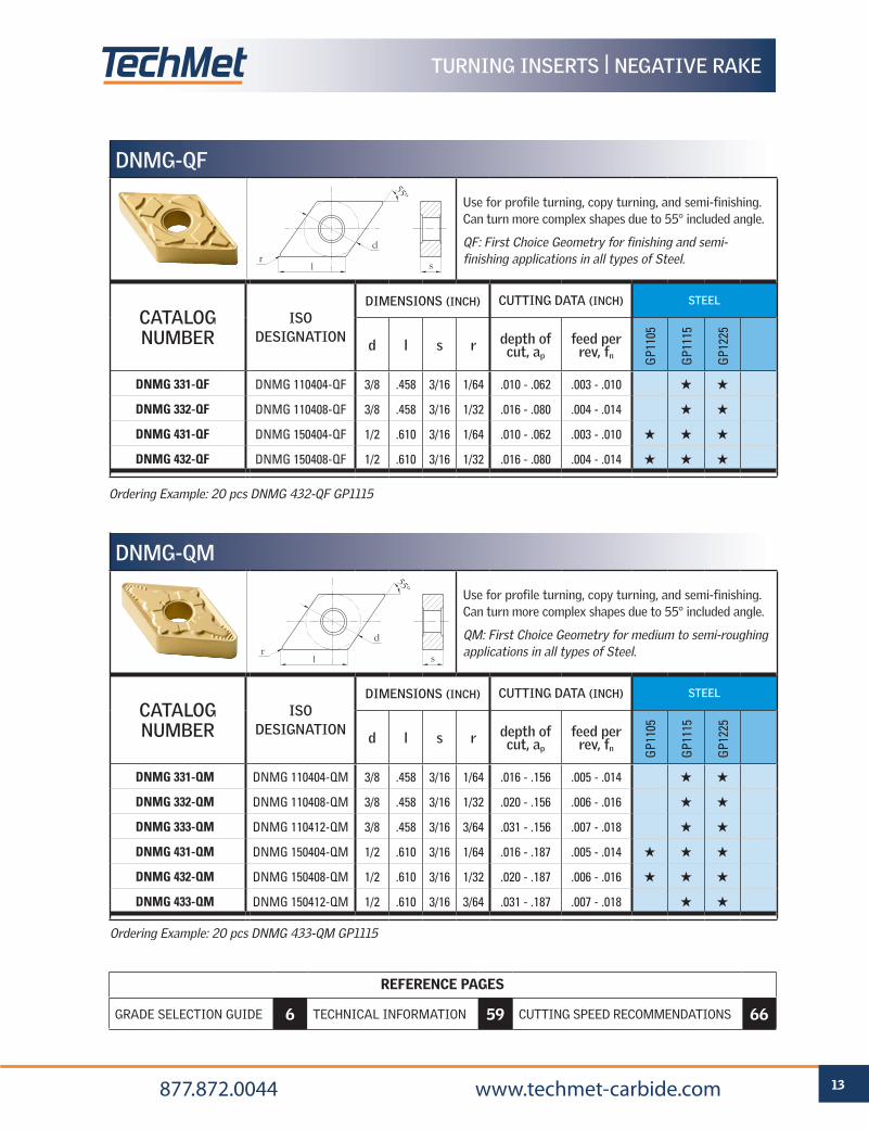
Ordering Example: 20 pcs DNMG 432-QF GP1115
DNMG-QF
Use for profile turning, copy turning, and semi-finishing. Can turn more complex shapes due to 55° included angle.
QF: First Choice Geometry for finishing and semi-finishing applications in all types of Steel.
CATALOG NUMBER
ISO DESIGNATION
DIMENSIONS (INCH) CUTTING DATA (INCH) STEEL
d l s r depth of cut, ap
feed per rev, fn G
P110
5
GP1
115
GP1
225
DNMG 331-QF DNMG 110404-QF 3/8 .458 3/16 1/64 .010 - .062 .003 - .010 H H
DNMG 332-QF DNMG 110408-QF 3/8 .458 3/16 1/32 .016 - .080 .004 - .014 H H
DNMG 431-QF DNMG 150404-QF 1/2 .610 3/16 1/64 .010 - .062 .003 - .010 H H H
DNMG 432-QF DNMG 150408-QF 1/2 .610 3/16 1/32 .016 - .080 .004 - .014 H H H
d
l sr
55º
Ordering Example: 20 pcs DNMG 433-QM GP1115
DNMG-QM
Use for profile turning, copy turning, and semi-finishing. Can turn more complex shapes due to 55° included angle.
QM: First Choice Geometry for medium to semi-roughing applications in all types of Steel.
CATALOG NUMBER
ISO DESIGNATION
DIMENSIONS (INCH) CUTTING DATA (INCH) STEEL
d l s r depth of cut, ap
feed per rev, fn G
P110
5
GP1
115
GP1
225
DNMG 331-QM DNMG 110404-QM 3/8 .458 3/16 1/64 .016 - .156 .005 - .014 H H
DNMG 332-QM DNMG 110408-QM 3/8 .458 3/16 1/32 .020 - .156 .006 - .016 H H
DNMG 333-QM DNMG 110412-QM 3/8 .458 3/16 3/64 .031 - .156 .007 - .018 H H
DNMG 431-QM DNMG 150404-QM 1/2 .610 3/16 1/64 .016 - .187 .005 - .014 H H H
DNMG 432-QM DNMG 150408-QM 1/2 .610 3/16 1/32 .020 - .187 .006 - .016 H H H
DNMG 433-QM DNMG 150412-QM 1/2 .610 3/16 3/64 .031 - .187 .007 - .018 H H
d
l sr
55º

REFERENCE PAGES
GRADE SELECTION GUIDE 6 TECHNICAL INFORMATION 59 CUTTING SPEED RECOMMENDATIONS 66
14 877.872.0044 www.techmet-carbide.com
Ordering Example: 20 pcs DNMG 433-SM GM1125
DNMG-SMUse for profile turning, copy turning, and semi-finishing. Can turn more complex shapes due to 55° included angle.
SM: Keen edge geometry especially for Stainless Steel. Unique edgeline reduces work hardening. Semi-finishing to rough machining.
CATALOG NUMBER
ISO DESIGNATION
DIMENSIONS (INCH) CUTTING DATA (INCH) STAINLESS STEEL
d l s r depth of cut, ap
feed per rev, fn G
M11
25
GM
3125
DNMG 331-SM DNMG 110404-SM 3/8 .458 3/16 1/64 .016 - .141 .006 - .011 H
DNMG 332-SM DNMG 110408-SM 3/8 .458 3/16 1/32 .020 - .141 .006 - .012 H H
DNMG 333-SM DNMG 110412-SM 3/8 .458 3/16 3/64 .031 - .141 .007 - .013 H H
DNMG 431-SM DNMG 150404-SM 1/2 .610 3/16 1/64 .016 - .172 .006 - .011 H H
DNMG 432-SM DNMG 150408-SM 1/2 .610 3/16 1/32 .020 - .172 .006 - .012 H H
DNMG 433-SM DNMG 150412-SM 1/2 .610 3/16 3/64 .031 - .172 .007 - .013 H H
d
l sr
55ºOrdering Example: 20 pcs DNMG 432-SF GS3115
NOTE: The primary application area for grade GS3115 is in stainless steel workpiece materials. GS3115 is also suitable for use with iron-based, cobalt-based and nickel-based Heat Resistant Super Alloys.
DNMG-SFUse for profile turning, copy turning, and semi-finishing. Can turn more complex shapes due to 55° included angle.
SF: Ultra-sharp cutting edge geometry for finishing in Stainless Steels. Low cutting forces and superior workpiece surface finish without burrs.
CATALOG NUMBER
ISO DESIGNATION
DIMENSIONS (INCH) CUTTING DATA (INCH) STAINLESS STEEL
d l s r depth of cut, ap
feed per rev, fn G
S311
5
DNMG 431-SF DNMG 150404-SF 1/2 .610 3/16 1/64 .004 - .060 .002 - .012 H
DNMG 432-SF DNMG 150408-SF 1/2 .610 3/16 1/32 .004 - .060 .002 - .012 H
d
l sr
55º
TURNING INSERTS | NEGATIVE RAKE
REFERENCE PAGES
GRADE SELECTION GUIDE 6 TECHNICAL INFORMATION 59 CUTTING SPEED RECOMMENDATIONS 66
15 877.872.0044 www.techmet-carbide.com
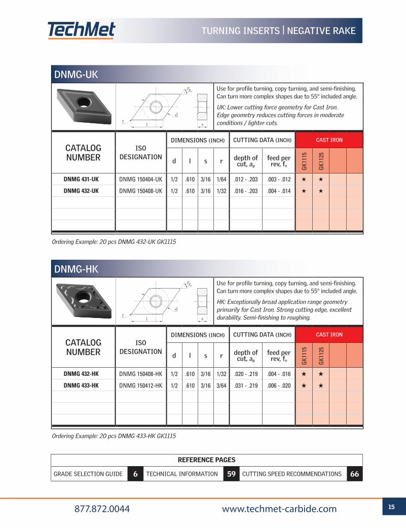
Ordering Example: 20 pcs DNMG 433-HK GK1115
DNMG-HKUse for profile turning, copy turning, and semi-finishing. Can turn more complex shapes due to 55° included angle.
HK: Exceptionally broad application range geometry primarily for Cast Iron. Strong cutting edge, excellent durability. Semi-finishing to roughing.
CATALOG NUMBER
ISO DESIGNATION
DIMENSIONS (INCH) CUTTING DATA (INCH) CAST IRON
d l s r depth of cut, ap
feed per rev, fn G
K111
5
GK1
125
DNMG 432-HK DNMG 150408-HK 1/2 .610 3/16 1/32 .020 - .219 .004 - .016 H H
DNMG 433-HK DNMG 150412-HK 1/2 .610 3/16 3/64 .031 - .219 .006 - .020 H H
Ordering Example: 20 pcs DNMG 432-UK GK1115
DNMG-UKUse for profile turning, copy turning, and semi-finishing. Can turn more complex shapes due to 55° included angle.
UK: Lower cutting force geometry for Cast Iron. Edge geometry reduces cutting forces in moderate conditions / lighter cuts.
CATALOG NUMBER
ISO DESIGNATION
DIMENSIONS (INCH) CUTTING DATA (INCH) CAST IRON
d l s r depth of cut, ap
feed per rev, fn G
K111
5
GK1
125
DNMG 431-UK DNMG 150404-UK 1/2 .610 3/16 1/64 .012 - .203 .003 - .012 H H
DNMG 432-UK DNMG 150408-UK 1/2 .610 3/16 1/32 .016 - .203 .004 - .014 H H
d
l sr
55º
d
l sr
55º
TURNING INSERTS | NEGATIVE RAKE
REFERENCE PAGES
GRADE SELECTION GUIDE 6 TECHNICAL INFORMATION 59 CUTTING SPEED RECOMMENDATIONS 66
16 877.872.0044 www.techmet-carbide.com
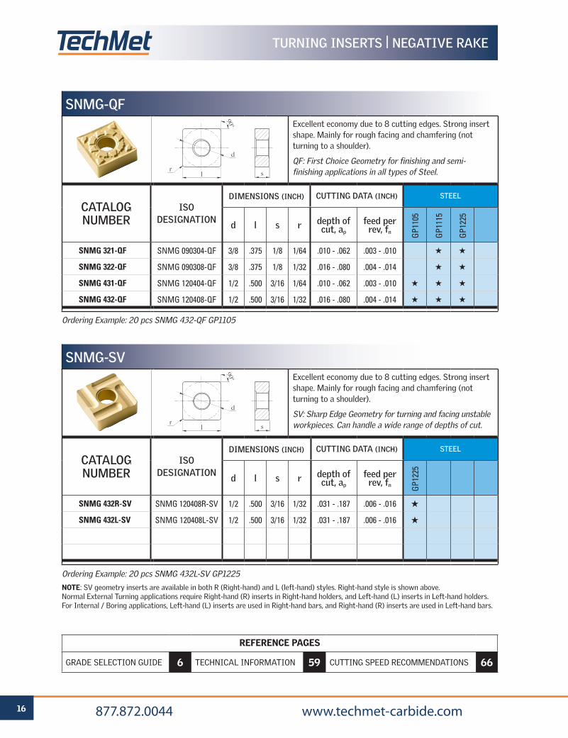
Ordering Example: 20 pcs SNMG 432L-SV GP1225
NOTE: SV geometry inserts are available in both R (Right-hand) and L (left-hand) styles. Right-hand style is shown above. Normal External Turning applications require Right-hand (R) inserts in Right-hand holders, and Left-hand (L) inserts in Left-hand holders. For Internal / Boring applications, Left-hand (L) inserts are used in Right-hand bars, and Right-hand (R) inserts are used in Left-hand bars.
SNMG-SVExcellent economy due to 8 cutting edges. Strong insert shape. Mainly for rough facing and chamfering (not turning to a shoulder).
SV: Sharp Edge Geometry for turning and facing unstable workpieces. Can handle a wide range of depths of cut.
CATALOG NUMBER
ISO DESIGNATION
DIMENSIONS (INCH) CUTTING DATA (INCH) STEEL
d l s r depth of cut, ap
feed per rev, fn G
P122
5
SNMG 432R-SV SNMG 120408R-SV 1/2 .500 3/16 1/32 .031 - .187 .006 - .016 H
SNMG 432L-SV SNMG 120408L-SV 1/2 .500 3/16 1/32 .031 - .187 .006 - .016 H
Ordering Example: 20 pcs SNMG 432-QF GP1105
d
l sr
90º
TURNING INSERTS | NEGATIVE RAKE
SNMG-QFExcellent economy due to 8 cutting edges. Strong insert shape. Mainly for rough facing and chamfering (not turning to a shoulder).
QF: First Choice Geometry for finishing and semi-finishing applications in all types of Steel.
CATALOG NUMBER
ISO DESIGNATION
DIMENSIONS (INCH) CUTTING DATA (INCH) STEEL
d l s r depth of cut, ap
feed per rev, fn G
P110
5
GP1
115
GP1
225
SNMG 321-QF SNMG 090304-QF 3/8 .375 1/8 1/64 .010 - .062 .003 - .010 H H
SNMG 322-QF SNMG 090308-QF 3/8 .375 1/8 1/32 .016 - .080 .004 - .014 H H
SNMG 431-QF SNMG 120404-QF 1/2 .500 3/16 1/64 .010 - .062 .003 - .010 H H H
SNMG 432-QF SNMG 120408-QF 1/2 .500 3/16 1/32 .016 - .080 .004 - .014 H H H
d
l sr
90º
REFERENCE PAGES
GRADE SELECTION GUIDE 6 TECHNICAL INFORMATION 59 CUTTING SPEED RECOMMENDATIONS 66
17 877.872.0044 www.techmet-carbide.com
TURNING INSERTS | NEGATIVE RAKE
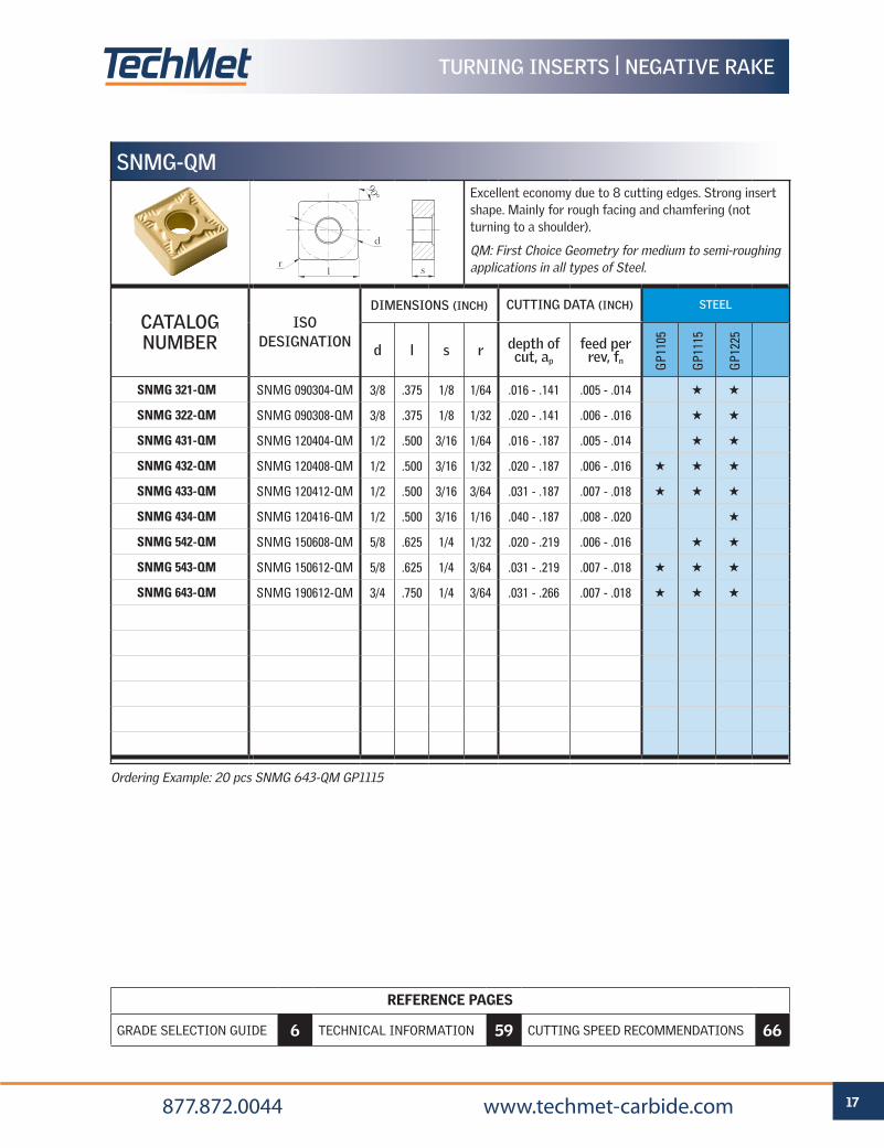
Ordering Example: 20 pcs SNMG 643-QM GP1115
SNMG-QMExcellent economy due to 8 cutting edges. Strong insert shape. Mainly for rough facing and chamfering (not turning to a shoulder).
QM: First Choice Geometry for medium to semi-roughing applications in all types of Steel.
CATALOG NUMBER
ISO DESIGNATION
DIMENSIONS (INCH) CUTTING DATA (INCH) STEEL
d l s r depth of cut, ap
feed per rev, fn G
P110
5
GP1
115
GP1
225
SNMG 321-QM SNMG 090304-QM 3/8 .375 1/8 1/64 .016 - .141 .005 - .014 H H
SNMG 322-QM SNMG 090308-QM 3/8 .375 1/8 1/32 .020 - .141 .006 - .016 H H
SNMG 431-QM SNMG 120404-QM 1/2 .500 3/16 1/64 .016 - .187 .005 - .014 H H
SNMG 432-QM SNMG 120408-QM 1/2 .500 3/16 1/32 .020 - .187 .006 - .016 H H H
SNMG 433-QM SNMG 120412-QM 1/2 .500 3/16 3/64 .031 - .187 .007 - .018 H H H
SNMG 434-QM SNMG 120416-QM 1/2 .500 3/16 1/16 .040 - .187 .008 - .020 H
SNMG 542-QM SNMG 150608-QM 5/8 .625 1/4 1/32 .020 - .219 .006 - .016 H H
SNMG 543-QM SNMG 150612-QM 5/8 .625 1/4 3/64 .031 - .219 .007 - .018 H H H
SNMG 643-QM SNMG 190612-QM 3/4 .750 1/4 3/64 .031 - .266 .007 - .018 H H H
d
l sr
90º
REFERENCE PAGES
GRADE SELECTION GUIDE 6 TECHNICAL INFORMATION 59 CUTTING SPEED RECOMMENDATIONS 66
18 877.872.0044 www.techmet-carbide.com
TURNING INSERTS | NEGATIVE RAKE
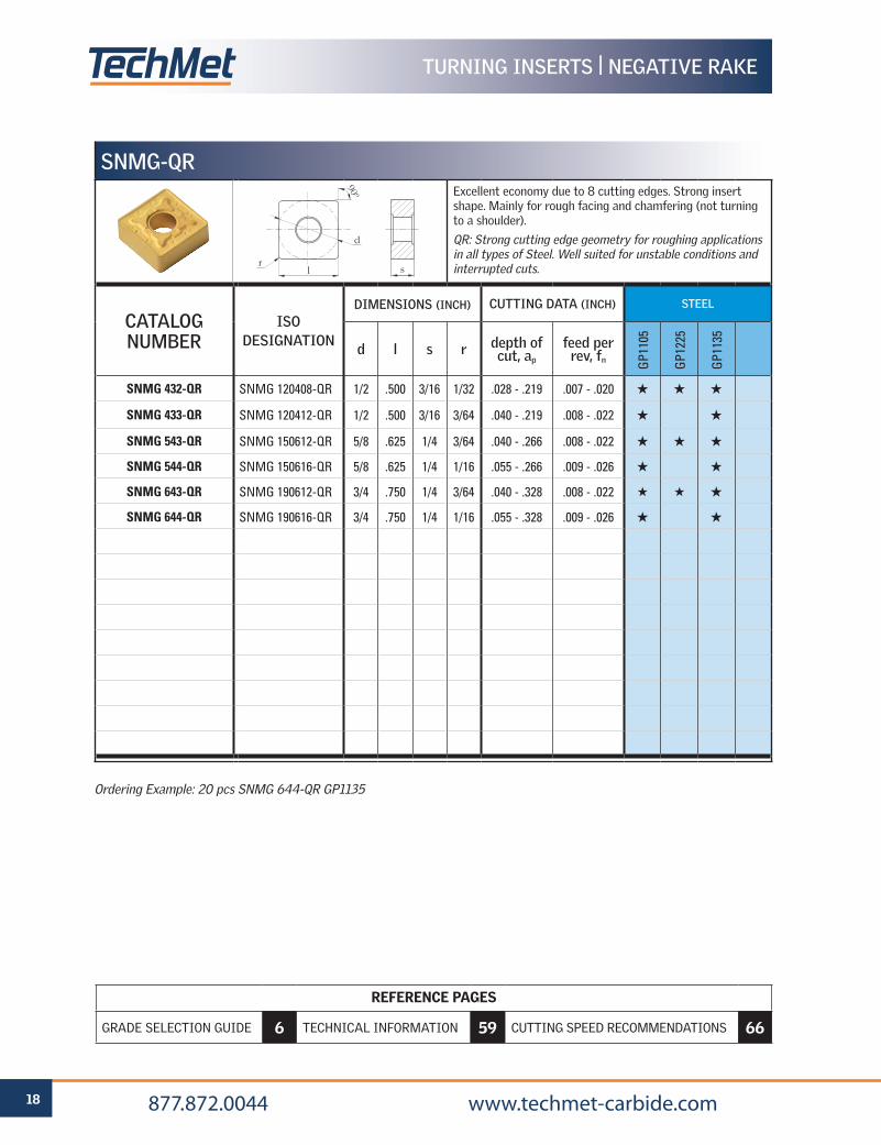
SNMG-QRExcellent economy due to 8 cutting edges. Strong insert shape. Mainly for rough facing and chamfering (not turning to a shoulder).
QR: Strong cutting edge geometry for roughing applications in all types of Steel. Well suited for unstable conditions and interrupted cuts.
CATALOG NUMBER
ISO DESIGNATION
DIMENSIONS (INCH) CUTTING DATA (INCH) STEEL
d l s r depth of cut, ap
feed per rev, fn G
P110
5
GP1
225
GP1
135
SNMG 432-QR SNMG 120408-QR 1/2 .500 3/16 1/32 .028 - .219 .007 - .020 H H H
SNMG 433-QR SNMG 120412-QR 1/2 .500 3/16 3/64 .040 - .219 .008 - .022 H H
SNMG 543-QR SNMG 150612-QR 5/8 .625 1/4 3/64 .040 - .266 .008 - .022 H H H
SNMG 544-QR SNMG 150616-QR 5/8 .625 1/4 1/16 .055 - .266 .009 - .026 H H
SNMG 643-QR SNMG 190612-QR 3/4 .750 1/4 3/64 .040 - .328 .008 - .022 H H H
SNMG 644-QR SNMG 190616-QR 3/4 .750 1/4 1/16 .055 - .328 .009 - .026 H H
d
l sr
90º
Ordering Example: 20 pcs SNMG 644-QR GP1135
REFERENCE PAGES
GRADE SELECTION GUIDE 6 TECHNICAL INFORMATION 59 CUTTING SPEED RECOMMENDATIONS 66
19 877.872.0044 www.techmet-carbide.com
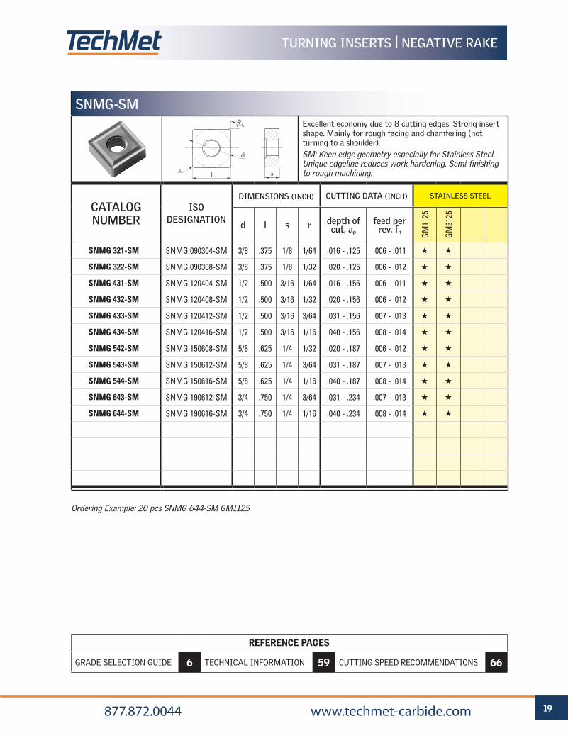
Ordering Example: 20 pcs SNMG 644-SM GM1125
SNMG-SMExcellent economy due to 8 cutting edges. Strong insert shape. Mainly for rough facing and chamfering (not turning to a shoulder).SM: Keen edge geometry especially for Stainless Steel. Unique edgeline reduces work hardening. Semi-finishing to rough machining.
CATALOG NUMBER
ISO DESIGNATION
DIMENSIONS (INCH) CUTTING DATA (INCH) STAINLESS STEEL
d l s r depth of cut, ap
feed per rev, fn G
M11
25
GM
3125
SNMG 321-SM SNMG 090304-SM 3/8 .375 1/8 1/64 .016 - .125 .006 - .011 H H
SNMG 322-SM SNMG 090308-SM 3/8 .375 1/8 1/32 .020 - .125 .006 - .012 H H
SNMG 431-SM SNMG 120404-SM 1/2 .500 3/16 1/64 .016 - .156 .006 - .011 H H
SNMG 432-SM SNMG 120408-SM 1/2 .500 3/16 1/32 .020 - .156 .006 - .012 H H
SNMG 433-SM SNMG 120412-SM 1/2 .500 3/16 3/64 .031 - .156 .007 - .013 H H
SNMG 434-SM SNMG 120416-SM 1/2 .500 3/16 1/16 .040 - .156 .008 - .014 H H
SNMG 542-SM SNMG 150608-SM 5/8 .625 1/4 1/32 .020 - .187 .006 - .012 H H
SNMG 543-SM SNMG 150612-SM 5/8 .625 1/4 3/64 .031 - .187 .007 - .013 H H
SNMG 544-SM SNMG 150616-SM 5/8 .625 1/4 1/16 .040 - .187 .008 - .014 H H
SNMG 643-SM SNMG 190612-SM 3/4 .750 1/4 3/64 .031 - .234 .007 - .013 H H
SNMG 644-SM SNMG 190616-SM 3/4 .750 1/4 1/16 .040 - .234 .008 - .014 H H
d
l sr
90º
TURNING INSERTS | NEGATIVE RAKE
REFERENCE PAGES
GRADE SELECTION GUIDE 6 TECHNICAL INFORMATION 59 CUTTING SPEED RECOMMENDATIONS 66
20 877.872.0044 www.techmet-carbide.com
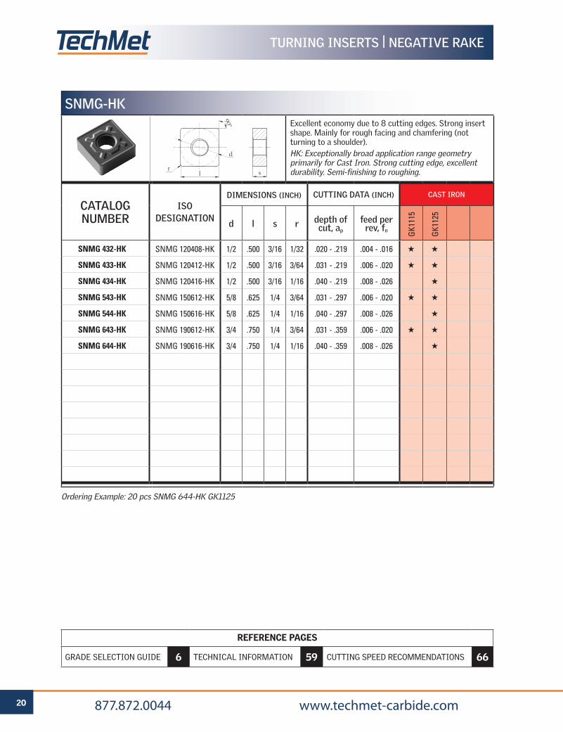
Ordering Example: 20 pcs SNMG 644-HK GK1125
SNMG-HKExcellent economy due to 8 cutting edges. Strong insert shape. Mainly for rough facing and chamfering (not turning to a shoulder).HK: Exceptionally broad application range geometry primarily for Cast Iron. Strong cutting edge, excellent durability. Semi-finishing to roughing.
CATALOG NUMBER
ISO DESIGNATION
DIMENSIONS (INCH) CUTTING DATA (INCH) CAST IRON
d l s r depth of cut, ap
feed per rev, fn G
K111
5
GK1
125
SNMG 432-HK SNMG 120408-HK 1/2 .500 3/16 1/32 .020 - .219 .004 - .016 H H
SNMG 433-HK SNMG 120412-HK 1/2 .500 3/16 3/64 .031 - .219 .006 - .020 H H
SNMG 434-HK SNMG 120416-HK 1/2 .500 3/16 1/16 .040 - .219 .008 - .026 H
SNMG 543-HK SNMG 150612-HK 5/8 .625 1/4 3/64 .031 - .297 .006 - .020 H H
SNMG 544-HK SNMG 150616-HK 5/8 .625 1/4 1/16 .040 - .297 .008 - .026 H
SNMG 643-HK SNMG 190612-HK 3/4 .750 1/4 3/64 .031 - .359 .006 - .020 H H
SNMG 644-HK SNMG 190616-HK 3/4 .750 1/4 1/16 .040 - .359 .008 - .026 H
d
l sr
90º
TURNING INSERTS | NEGATIVE RAKE
REFERENCE PAGES
GRADE SELECTION GUIDE 6 TECHNICAL INFORMATION 59 CUTTING SPEED RECOMMENDATIONS 66
21 877.872.0044 www.techmet-carbide.com
Ordering Example: 20 pcs TNMG 332L-SV GP1225
NOTE: SV geometry inserts are available in both R (Right-hand) and L (left-hand) styles. Right-hand style is shown above. Normal External Turning applications require Right-hand (R) inserts in Right-hand holders, and Left-hand (L) inserts in Left-hand holders. For Internal / Boring applications, Left-hand (L) inserts are used in Right-hand bars, and Right-hand (R) inserts are used in Left-hand bars.
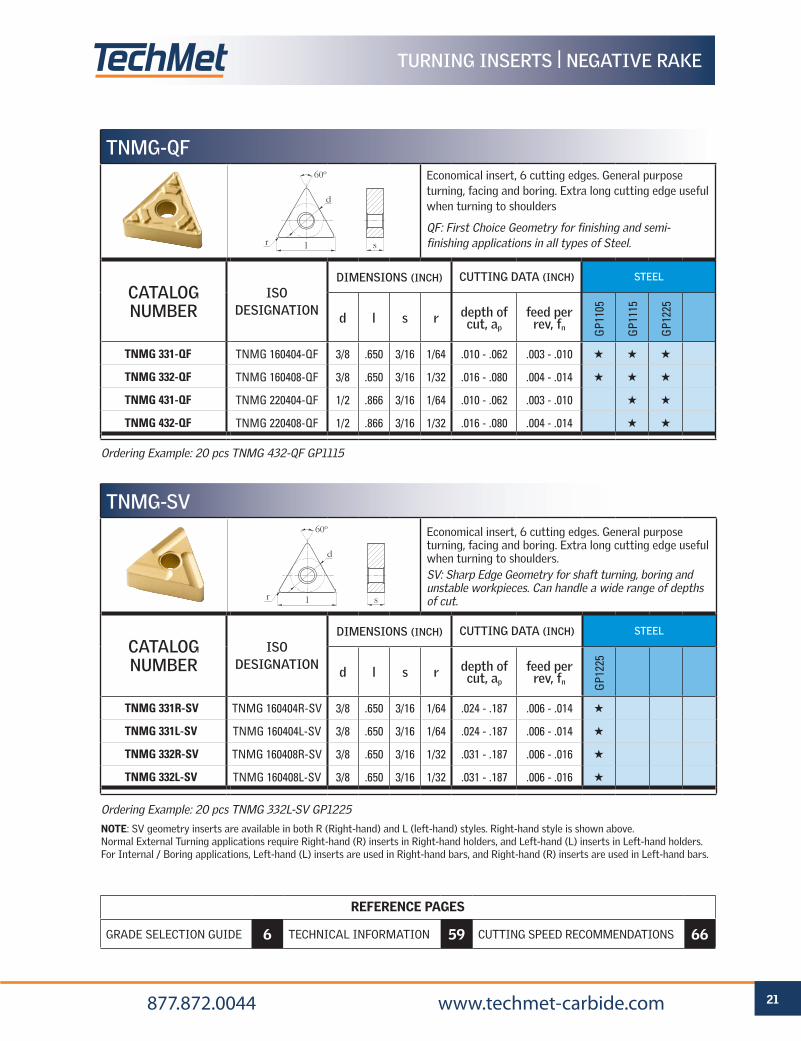
TNMG-SVEconomical insert, 6 cutting edges. General purpose turning, facing and boring. Extra long cutting edge useful when turning to shoulders.SV: Sharp Edge Geometry for shaft turning, boring and unstable workpieces. Can handle a wide range of depths of cut.
CATALOG NUMBER
ISO DESIGNATION
DIMENSIONS (INCH) CUTTING DATA (INCH) STEEL
d l s r depth of cut, ap
feed per rev, fn G
P122
5
TNMG 331R-SV TNMG 160404R-SV 3/8 .650 3/16 1/64 .024 - .187 .006 - .014 H
TNMG 331L-SV TNMG 160404L-SV 3/8 .650 3/16 1/64 .024 - .187 .006 - .014 H
TNMG 332R-SV TNMG 160408R-SV 3/8 .650 3/16 1/32 .031 - .187 .006 - .016 H
TNMG 332L-SV TNMG 160408L-SV 3/8 .650 3/16 1/32 .031 - .187 .006 - .016 H
Ordering Example: 20 pcs TNMG 432-QF GP1115
d
sr l
60º
TURNING INSERTS | NEGATIVE RAKE
TNMG-QFEconomical insert, 6 cutting edges. General purpose turning, facing and boring. Extra long cutting edge useful when turning to shoulders
QF: First Choice Geometry for finishing and semi-finishing applications in all types of Steel.
CATALOG NUMBER
ISO DESIGNATION
DIMENSIONS (INCH) CUTTING DATA (INCH) STEEL
d l s r depth of cut, ap
feed per rev, fn G
P110
5
GP1
115
GP1
225
TNMG 331-QF TNMG 160404-QF 3/8 .650 3/16 1/64 .010 - .062 .003 - .010 H H H
TNMG 332-QF TNMG 160408-QF 3/8 .650 3/16 1/32 .016 - .080 .004 - .014 H H H
TNMG 431-QF TNMG 220404-QF 1/2 .866 3/16 1/64 .010 - .062 .003 - .010 H H
TNMG 432-QF TNMG 220408-QF 1/2 .866 3/16 1/32 .016 - .080 .004 - .014 H H
d
sr l
60º
REFERENCE PAGES
GRADE SELECTION GUIDE 6 TECHNICAL INFORMATION 59 CUTTING SPEED RECOMMENDATIONS 66
22 877.872.0044 www.techmet-carbide.com
TURNING INSERTS | NEGATIVE RAKE
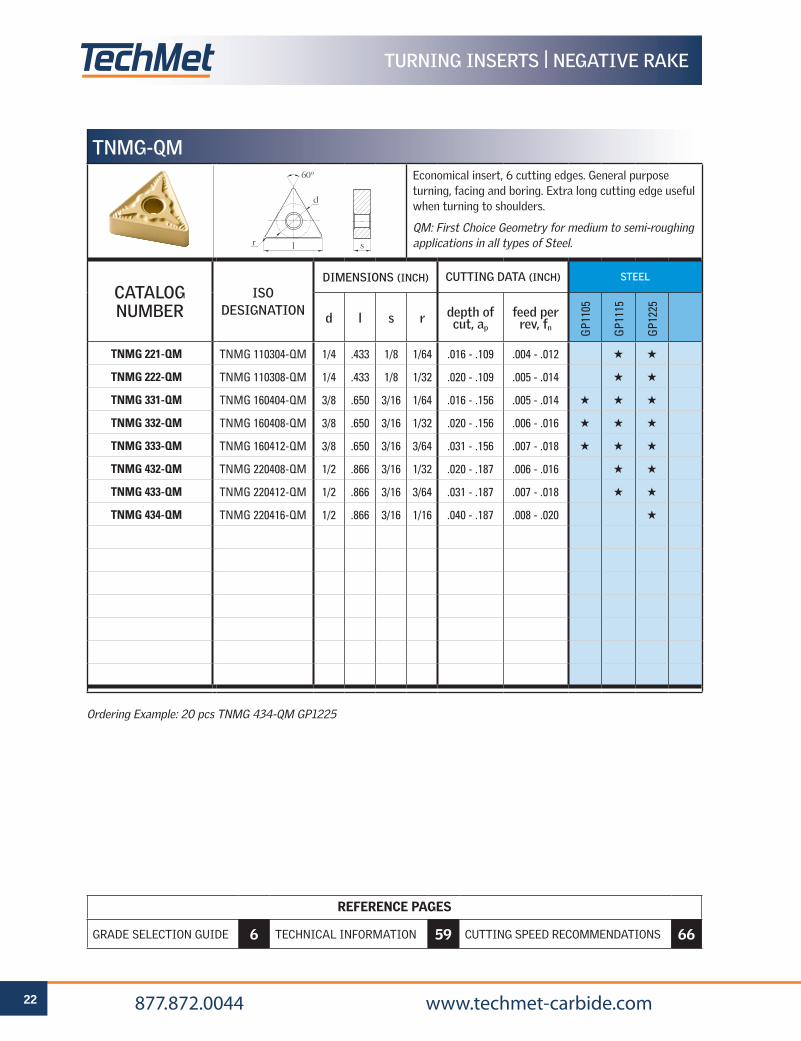
Ordering Example: 20 pcs TNMG 434-QM GP1225
TNMG-QMEconomical insert, 6 cutting edges. General purpose turning, facing and boring. Extra long cutting edge useful when turning to shoulders.
QM: First Choice Geometry for medium to semi-roughing applications in all types of Steel.
CATALOG NUMBER
ISO DESIGNATION
DIMENSIONS (INCH) CUTTING DATA (INCH) STEEL
d l s r depth of cut, ap
feed per rev, fn G
P110
5
GP1
115
GP1
225
TNMG 221-QM TNMG 110304-QM 1/4 .433 1/8 1/64 .016 - .109 .004 - .012 H H
TNMG 222-QM TNMG 110308-QM 1/4 .433 1/8 1/32 .020 - .109 .005 - .014 H H
TNMG 331-QM TNMG 160404-QM 3/8 .650 3/16 1/64 .016 - .156 .005 - .014 H H H
TNMG 332-QM TNMG 160408-QM 3/8 .650 3/16 1/32 .020 - .156 .006 - .016 H H H
TNMG 333-QM TNMG 160412-QM 3/8 .650 3/16 3/64 .031 - .156 .007 - .018 H H H
TNMG 432-QM TNMG 220408-QM 1/2 .866 3/16 1/32 .020 - .187 .006 - .016 H H
TNMG 433-QM TNMG 220412-QM 1/2 .866 3/16 3/64 .031 - .187 .007 - .018 H H
TNMG 434-QM TNMG 220416-QM 1/2 .866 3/16 1/16 .040 - .187 .008 - .020 H
d
sr l
60º
REFERENCE PAGES
GRADE SELECTION GUIDE 6 TECHNICAL INFORMATION 59 CUTTING SPEED RECOMMENDATIONS 66
23 877.872.0044 www.techmet-carbide.com
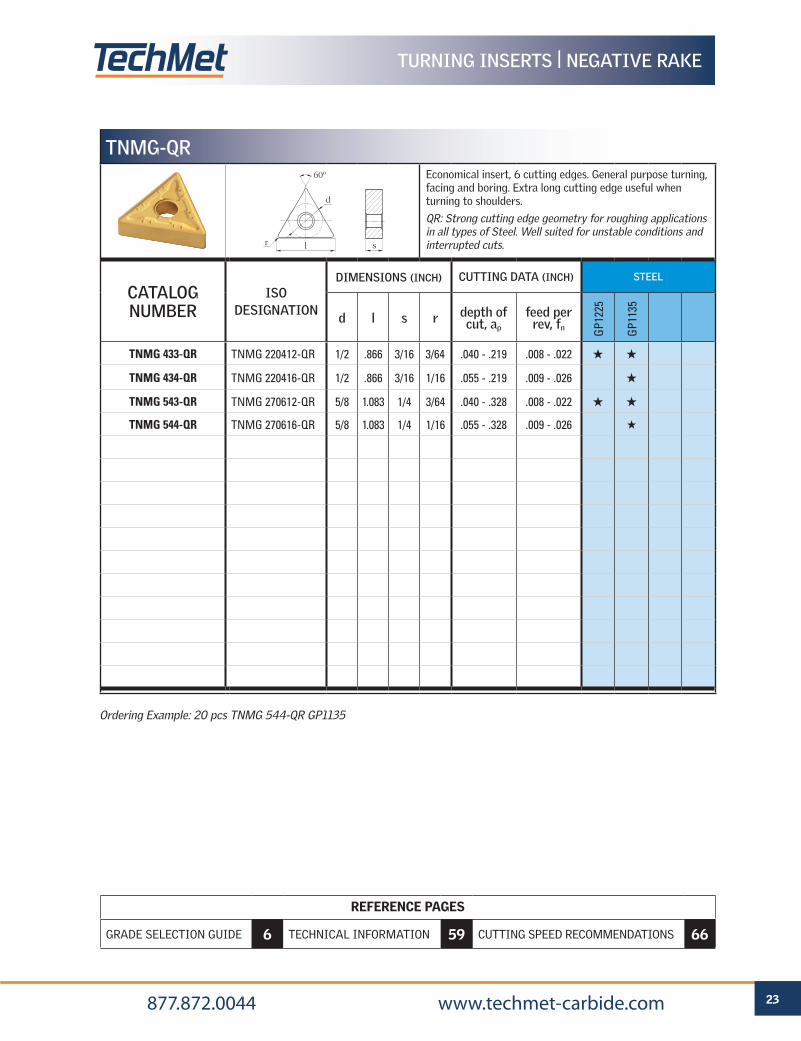
Ordering Example: 20 pcs TNMG 544-QR GP1135
TNMG-QREconomical insert, 6 cutting edges. General purpose turning, facing and boring. Extra long cutting edge useful when turning to shoulders.
QR: Strong cutting edge geometry for roughing applications in all types of Steel. Well suited for unstable conditions and interrupted cuts.
CATALOG NUMBER
ISO DESIGNATION
DIMENSIONS (INCH) CUTTING DATA (INCH) STEEL
d l s r depth of cut, ap
feed per rev, fn G
P122
5
GP1
135
TNMG 433-QR TNMG 220412-QR 1/2 .866 3/16 3/64 .040 - .219 .008 - .022 H H
TNMG 434-QR TNMG 220416-QR 1/2 .866 3/16 1/16 .055 - .219 .009 - .026 H
TNMG 543-QR TNMG 270612-QR 5/8 1.083 1/4 3/64 .040 - .328 .008 - .022 H H
TNMG 544-QR TNMG 270616-QR 5/8 1.083 1/4 1/16 .055 - .328 .009 - .026 H
d
sr l
60º
TURNING INSERTS | NEGATIVE RAKE
REFERENCE PAGES
GRADE SELECTION GUIDE 6 TECHNICAL INFORMATION 59 CUTTING SPEED RECOMMENDATIONS 66
24 877.872.0044 www.techmet-carbide.com
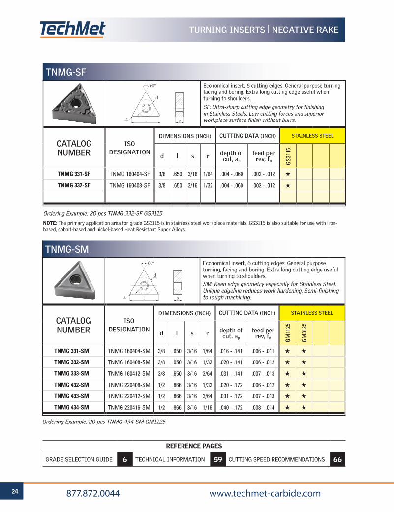
Ordering Example: 20 pcs TNMG 332-SF GS3115
NOTE: The primary application area for grade GS3115 is in stainless steel workpiece materials. GS3115 is also suitable for use with iron-based, cobalt-based and nickel-based Heat Resistant Super Alloys.
TNMG-SFEconomical insert, 6 cutting edges. General purpose turning, facing and boring. Extra long cutting edge useful when turning to shoulders.
SF: Ultra-sharp cutting edge geometry for finishing in Stainless Steels. Low cutting forces and superior workpiece surface finish without burrs.
CATALOG NUMBER
ISO DESIGNATION
DIMENSIONS (INCH) CUTTING DATA (INCH) STAINLESS STEEL
d l s r depth of cut, ap
feed per rev, fn G
S311
5
TNMG 331-SF TNMG 160404-SF 3/8 .650 3/16 1/64 .004 - .060 .002 - .012 H
TNMG 332-SF TNMG 160408-SF 3/8 .650 3/16 1/32 .004 - .060 .002 - .012 H
d
sr l
60º
Ordering Example: 20 pcs TNMG 434-SM GM1125
TNMG-SMEconomical insert, 6 cutting edges. General purpose turning, facing and boring. Extra long cutting edge useful when turning to shoulders.SM: Keen edge geometry especially for Stainless Steel. Unique edgeline reduces work hardening. Semi-finishing to rough machining.
CATALOG NUMBER
ISO DESIGNATION
DIMENSIONS (INCH) CUTTING DATA (INCH) STAINLESS STEEL
d l s r depth of cut, ap
feed per rev, fn G
M11
25
GM
3125
TNMG 331-SM TNMG 160404-SM 3/8 .650 3/16 1/64 .016 - .141 .006 - .011 H H
TNMG 332-SM TNMG 160408-SM 3/8 .650 3/16 1/32 .020 - .141 .006 - .012 H H
TNMG 333-SM TNMG 160412-SM 3/8 .650 3/16 3/64 .031 - .141 .007 - .013 H H
TNMG 432-SM TNMG 220408-SM 1/2 .866 3/16 1/32 .020 - .172 .006 - .012 H H
TNMG 433-SM TNMG 220412-SM 1/2 .866 3/16 3/64 .031 - .172 .007 - .013 H H
TNMG 434-SM TNMG 220416-SM 1/2 .866 3/16 1/16 .040 - .172 .008 - .014 H H
d
sr l
60º
TURNING INSERTS | NEGATIVE RAKE
REFERENCE PAGES
GRADE SELECTION GUIDE 6 TECHNICAL INFORMATION 59 CUTTING SPEED RECOMMENDATIONS 66
25 877.872.0044 www.techmet-carbide.com
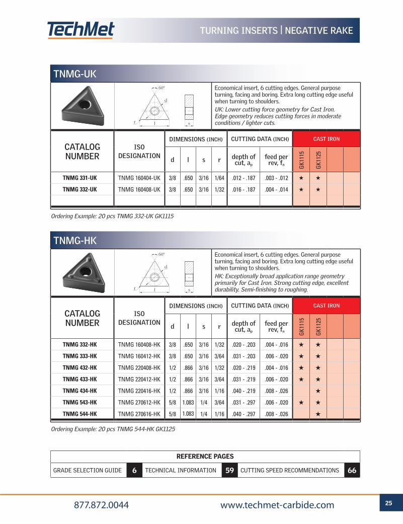
Ordering Example: 20 pcs TNMG 544-HK GK1125
TNMG-HKEconomical insert, 6 cutting edges. General purpose turning, facing and boring. Extra long cutting edge useful when turning to shoulders.HK: Exceptionally broad application range geometry primarily for Cast Iron. Strong cutting edge, excellent durability. Semi-finishing to roughing.
CATALOG NUMBER
ISO DESIGNATION
DIMENSIONS (INCH) CUTTING DATA (INCH) CAST IRON
d l s r depth of cut, ap
feed per rev, fn G
K111
5
GK1
125
TNMG 332-HK TNMG 160408-HK 3/8 .650 3/16 1/32 .020 - .203 .004 - .016 H H
TNMG 333-HK TNMG 160412-HK 3/8 .650 3/16 3/64 .031 - .203 .006 - .020 H H
TNMG 432-HK TNMG 220408-HK 1/2 .866 3/16 1/32 .020 - .219 .004 - .016 H H
TNMG 433-HK TNMG 220412-HK 1/2 .866 3/16 3/64 .031 - .219 .006 - .020 H H
TNMG 434-HK TNMG 220416-HK 1/2 .866 3/16 1/16 .040 - .219 .008 - .026 H
TNMG 543-HK TNMG 270612-HK 5/8 1.083 1/4 3/64 .031 - .297 .006 - .020 H H
TNMG 544-HK TNMG 270616-HK 5/8 1.083 1/4 1/16 .040 - .297 .008 - .026 H
Ordering Example: 20 pcs TNMG 332-UK GK1115
TNMG-UKEconomical insert, 6 cutting edges. General purpose turning, facing and boring. Extra long cutting edge useful when turning to shoulders.UK: Lower cutting force geometry for Cast Iron. Edge geometry reduces cutting forces in moderate conditions / lighter cuts.
CATALOG NUMBER
ISO DESIGNATION
DIMENSIONS (INCH) CUTTING DATA (INCH) CAST IRON
d l s r depth of cut, ap
feed per rev, fn G
K111
5
GK1
125
TNMG 331-UK TNMG 160404-UK 3/8 .650 3/16 1/64 .012 - .187 .003 - .012 H H
TNMG 332-UK TNMG 160408-UK 3/8 .650 3/16 1/32 .016 - .187 .004 - .014 H H
d
sr l
60º
d
sr l
60º
TURNING INSERTS | NEGATIVE RAKE
REFERENCE PAGES
GRADE SELECTION GUIDE 6 TECHNICAL INFORMATION 59 CUTTING SPEED RECOMMENDATIONS 66
26 877.872.0044 www.techmet-carbide.com
TURNING INSERTS | NEGATIVE RAKE
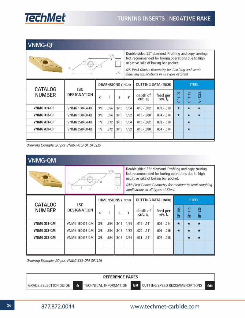
Ordering Example: 20 pcs VNMG 432-QF GP1115
VNMG-QFDouble-sided 35° diamond. Profiling and copy turning. Not recommended for boring operations due to high negative rake of boring bar pocket.
QF: First Choice Geometry for finishing and semi-finishing applications in all types of Steel.
CATALOG NUMBER
ISO DESIGNATION
DIMENSIONS (INCH) CUTTING DATA (INCH) STEEL
d l s r depth of cut, ap
feed per rev, fn G
P110
5
GP1
115
GP1
225
VNMG 331-QF VNMG 160404-QF 3/8 .654 3/16 1/64 .010 - .062 .003 - .010 H H H
VNMG 332-QF VNMG 160408-QF 3/8 .654 3/16 1/32 .016 - .080 .004 - .014 H H H
VNMG 431-QF VNMG 220404-QF 1/2 .872 3/16 1/64 .010 - .062 .003 - .010 H
VNMG 432-QF VNMG 220408-QF 1/2 .872 3/16 1/32 .016 - .080 .004 - .014 H
d
l s
r
35º
Ordering Example: 20 pcs VNMG 333-QM GP1115
VNMG-QMDouble-sided 35° diamond. Profiling and copy turning. Not recommended for boring operations due to high negative rake of boring bar pocket.
QM: First Choice Geometry for medium to semi-roughing applications in all types of Steel.
CATALOG NUMBER
ISO DESIGNATION
DIMENSIONS (INCH) CUTTING DATA (INCH) STEEL
d l s r depth of cut, ap
feed per rev, fn G
P110
5
GP1
115
GP1
225
VNMG 331-QM VNMG 160404-QM 3/8 .654 3/16 1/64 .016 - .141 .005 - .014 H H H
VNMG 332-QM VNMG 160408-QM 3/8 .654 3/16 1/32 .020 - .141 .006 - .016 H H H
VNMG 333-QM VNMG 160412-QM 3/8 .654 3/16 3/64 .031 - .141 .007 - .018 H H
d
l s
r
35º
REFERENCE PAGES
GRADE SELECTION GUIDE 6 TECHNICAL INFORMATION 59 CUTTING SPEED RECOMMENDATIONS 66
27 877.872.0044 www.techmet-carbide.com
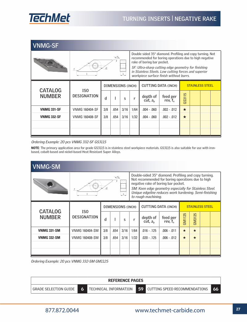
Ordering Example: 20 pcs VNMG 332-SM GM1125
VNMG-SMDouble-sided 35° diamond. Profiling and copy turning. Not recommended for boring operations due to high negative rake of boring bar pocket.SM: Keen edge geometry especially for Stainless Steel. Unique edgeline reduces work hardening. Semi-finishing to rough machining.
CATALOG NUMBER
ISO DESIGNATION
DIMENSIONS (INCH) CUTTING DATA (INCH) STAINLESS STEEL
d l s r depth of cut, ap
feed per rev, fn G
M11
25
GM
3125
VNMG 331-SM VNMG 160404-SM 3/8 .654 3/16 1/64 .016 - .125 .006 - .011 H H
VNMG 332-SM VNMG 160408-SM 3/8 .654 3/16 1/32 .020 - .125 .006 - .012 H H
d
l s
r
35º
Ordering Example: 20 pcs VNMG 332-SF GS3115
NOTE: The primary application area for grade GS3115 is in stainless steel workpiece materials. GS3115 is also suitable for use with iron-based, cobalt-based and nickel-based Heat Resistant Super Alloys.
VNMG-SFDouble sided 35° diamond. Profiling and copy turning. Not recommended for boring operations due to high negative rake of boring bar pocket.
SF: Ultra-sharp cutting edge geometry for finishing in Stainless Steels. Low cutting forces and superior workpiece surface finish without burrs.
CATALOG NUMBER
ISO DESIGNATION
DIMENSIONS (INCH) CUTTING DATA (INCH) STAINLESS STEEL
d l s r depth of cut, ap
feed per rev, fn G
S311
5
VNMG 331-SF VNMG 160404-SF 3/8 .654 3/16 1/64 .004 - .060 .002 - .012 H
VNMG 332-SF VNMG 160408-SF 3/8 .654 3/16 1/32 .004 - .060 .002 - .012 H
d
l s
r
35º
TURNING INSERTS | NEGATIVE RAKE
REFERENCE PAGES
GRADE SELECTION GUIDE 6 TECHNICAL INFORMATION 59 CUTTING SPEED RECOMMENDATIONS 66
28 877.872.0044 www.techmet-carbide.com
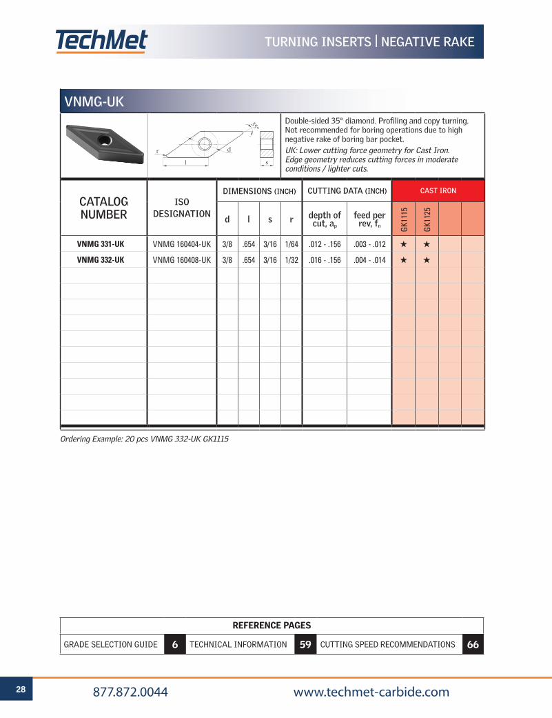
Ordering Example: 20 pcs VNMG 332-UK GK1115
VNMG-UKDouble-sided 35° diamond. Profiling and copy turning. Not recommended for boring operations due to high negative rake of boring bar pocket.UK: Lower cutting force geometry for Cast Iron. Edge geometry reduces cutting forces in moderate conditions / lighter cuts.
CATALOG NUMBER
ISO DESIGNATION
DIMENSIONS (INCH) CUTTING DATA (INCH) CAST IRON
d l s r depth of cut, ap
feed per rev, fn G
K111
5
GK1
125
VNMG 331-UK VNMG 160404-UK 3/8 .654 3/16 1/64 .012 - .156 .003 - .012 H H
VNMG 332-UK VNMG 160408-UK 3/8 .654 3/16 1/32 .016 - .156 .004 - .014 H H
d
l s
r
35º
TURNING INSERTS | NEGATIVE RAKE
REFERENCE PAGES
GRADE SELECTION GUIDE 6 TECHNICAL INFORMATION 59 CUTTING SPEED RECOMMENDATIONS 66
29 877.872.0044 www.techmet-carbide.com
TURNING INSERTS | NEGATIVE RAKE
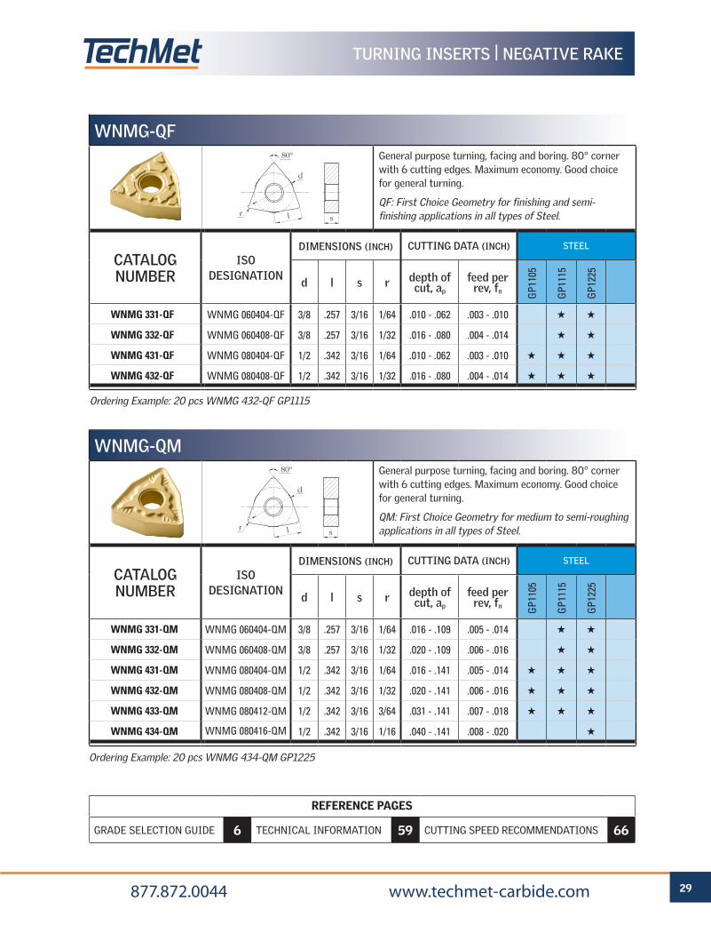
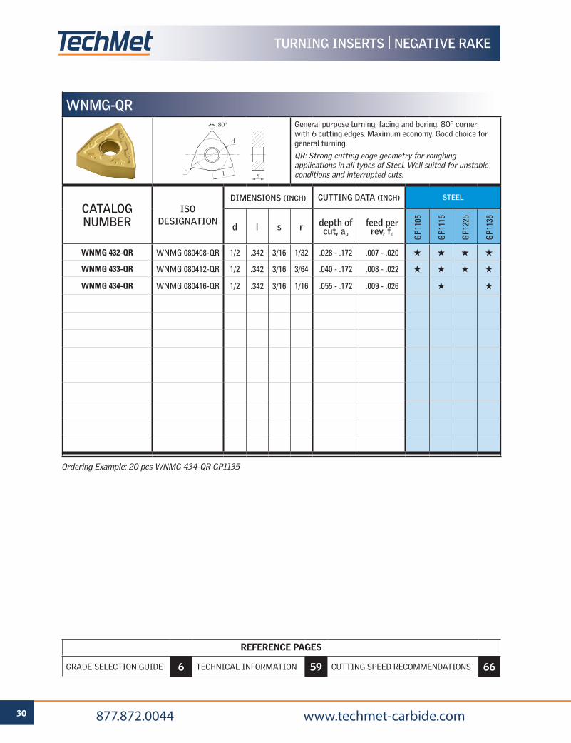
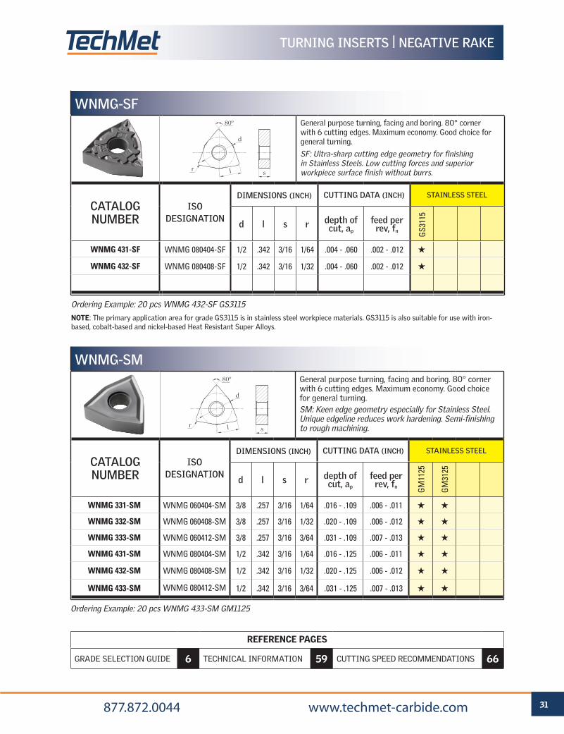
Ordering Example: 20 pcs WNMG 432-QF GP1115
WNMG-QFGeneral purpose turning, facing and boring. 80° corner with 6 cutting edges. Maximum economy. Good choice for general turning.
QF: First Choice Geometry for finishing and semi-finishing applications in all types of Steel.
CATALOG NUMBER
ISO DESIGNATION
DIMENSIONS (INCH) CUTTING DATA (INCH) STEEL
d l s r depth of cut, ap
feed per rev, fn G
P110
5
GP1
115
GP1
225
WNMG 331-QF WNMG 060404-QF 3/8 .257 3/16 1/64 .010 - .062 .003 - .010 H H
WNMG 332-QF WNMG 060408-QF 3/8 .257 3/16 1/32 .016 - .080 .004 - .014 H H
WNMG 431-QF WNMG 080404-QF 1/2 .342 3/16 1/64 .010 - .062 .003 - .010 H H H
WNMG 432-QF WNMG 080408-QF 1/2 .342 3/16 1/32 .016 - .080 .004 - .014 H H H
d
sr
80º
l
Ordering Example: 20 pcs WNMG 434-QM GP1225
WNMG-QMGeneral purpose turning, facing and boring. 80° corner with 6 cutting edges. Maximum economy. Good choice for general turning.
QM: First Choice Geometry for medium to semi-roughing applications in all types of Steel.
CATALOG NUMBER
ISO DESIGNATION
DIMENSIONS (INCH) CUTTING DATA (INCH) STEEL
d l s r depth of cut, ap
feed per rev, fn G
P110
5
GP1
115
GP1
225
WNMG 331-QM WNMG 060404-QM 3/8 .257 3/16 1/64 .016 - .109 .005 - .014 H H
WNMG 332-QM WNMG 060408-QM 3/8 .257 3/16 1/32 .020 - .109 .006 - .016 H H
WNMG 431-QM WNMG 080404-QM 1/2 .342 3/16 1/64 .016 - .141 .005 - .014 H H H
WNMG 432-QM WNMG 080408-QM 1/2 .342 3/16 1/32 .020 - .141 .006 - .016 H H H
WNMG 433-QM WNMG 080412-QM 1/2 .342 3/16 3/64 .031 - .141 .007 - .018 H H H
WNMG 434-QM WNMG 080416-QM 1/2 .342 3/16 1/16 .040 - .141 .008 - .020 H
d
sr
80º
l
REFERENCE PAGES
GRADE SELECTION GUIDE 6 TECHNICAL INFORMATION 59 CUTTING SPEED RECOMMENDATIONS 66
30 877.872.0044 www.techmet-carbide.com
TURNING INSERTS | NEGATIVE RAKE
Ordering Example: 20 pcs WNMG 434-QR GP1135
WNMG-QRGeneral purpose turning, facing and boring. 80° corner with 6 cutting edges. Maximum economy. Good choice for general turning.
QR: Strong cutting edge geometry for roughing applications in all types of Steel. Well suited for unstable conditions and interrupted cuts.
CATALOG NUMBER
ISO DESIGNATION
DIMENSIONS (INCH) CUTTING DATA (INCH) STEEL
d l s r depth of cut, ap
feed per rev, fn G
P110
5
GP1
115
GP1
225
GP1
135
WNMG 432-QR WNMG 080408-QR 1/2 .342 3/16 1/32 .028 - .172 .007 - .020 H H H H
WNMG 433-QR WNMG 080412-QR 1/2 .342 3/16 3/64 .040 - .172 .008 - .022 H H H H
WNMG 434-QR WNMG 080416-QR 1/2 .342 3/16 1/16 .055 - .172 .009 - .026 H H
d
sr
80º
l
REFERENCE PAGES
GRADE SELECTION GUIDE 6 TECHNICAL INFORMATION 59 CUTTING SPEED RECOMMENDATIONS 66
31 877.872.0044 www.techmet-carbide.com
Ordering Example: 20 pcs WNMG 433-SM GM1125
WNMG-SM
General purpose turning, facing and boring. 80° corner with 6 cutting edges. Maximum economy. Good choice for general turning.SM: Keen edge geometry especially for Stainless Steel. Unique edgeline reduces work hardening. Semi-finishing to rough machining.
CATALOG NUMBER
ISO DESIGNATION
DIMENSIONS (INCH) CUTTING DATA (INCH) STAINLESS STEEL
d l s r depth of cut, ap
feed per rev, fn G
M11
25
GM
3125
WNMG 331-SM WNMG 060404-SM 3/8 .257 3/16 1/64 .016 - .109 .006 - .011 H H
WNMG 332-SM WNMG 060408-SM 3/8 .257 3/16 1/32 .020 - .109 .006 - .012 H H
WNMG 333-SM WNMG 060412-SM 3/8 .257 3/16 3/64 .031 - .109 .007 - .013 H H
WNMG 431-SM WNMG 080404-SM 1/2 .342 3/16 1/64 .016 - .125 .006 - .011 H H
WNMG 432-SM WNMG 080408-SM 1/2 .342 3/16 1/32 .020 - .125 .006 - .012 H H
WNMG 433-SM WNMG 080412-SM 1/2 .342 3/16 3/64 .031 - .125 .007 - .013 H H
d
sr
80º
l
Ordering Example: 20 pcs WNMG 432-SF GS3115
NOTE: The primary application area for grade GS3115 is in stainless steel workpiece materials. GS3115 is also suitable for use with iron-based, cobalt-based and nickel-based Heat Resistant Super Alloys.
WNMG-SFGeneral purpose turning, facing and boring. 80° corner with 6 cutting edges. Maximum economy. Good choice for general turning.
SF: Ultra-sharp cutting edge geometry for finishing in Stainless Steels. Low cutting forces and superior workpiece surface finish without burrs.
CATALOG NUMBER
ISO DESIGNATION
DIMENSIONS (INCH) CUTTING DATA (INCH) STAINLESS STEEL
d l s r depth of cut, ap
feed per rev, fn G
S311
5
WNMG 431-SF WNMG 080404-SF 1/2 .342 3/16 1/64 .004 - .060 .002 - .012 H
WNMG 432-SF WNMG 080408-SF 1/2 .342 3/16 1/32 .004 - .060 .002 - .012 H
d
sr
80º
l
TURNING INSERTS | NEGATIVE RAKE
REFERENCE PAGES
GRADE SELECTION GUIDE 6 TECHNICAL INFORMATION 59 CUTTING SPEED RECOMMENDATIONS 66
32 877.872.0044 www.techmet-carbide.com
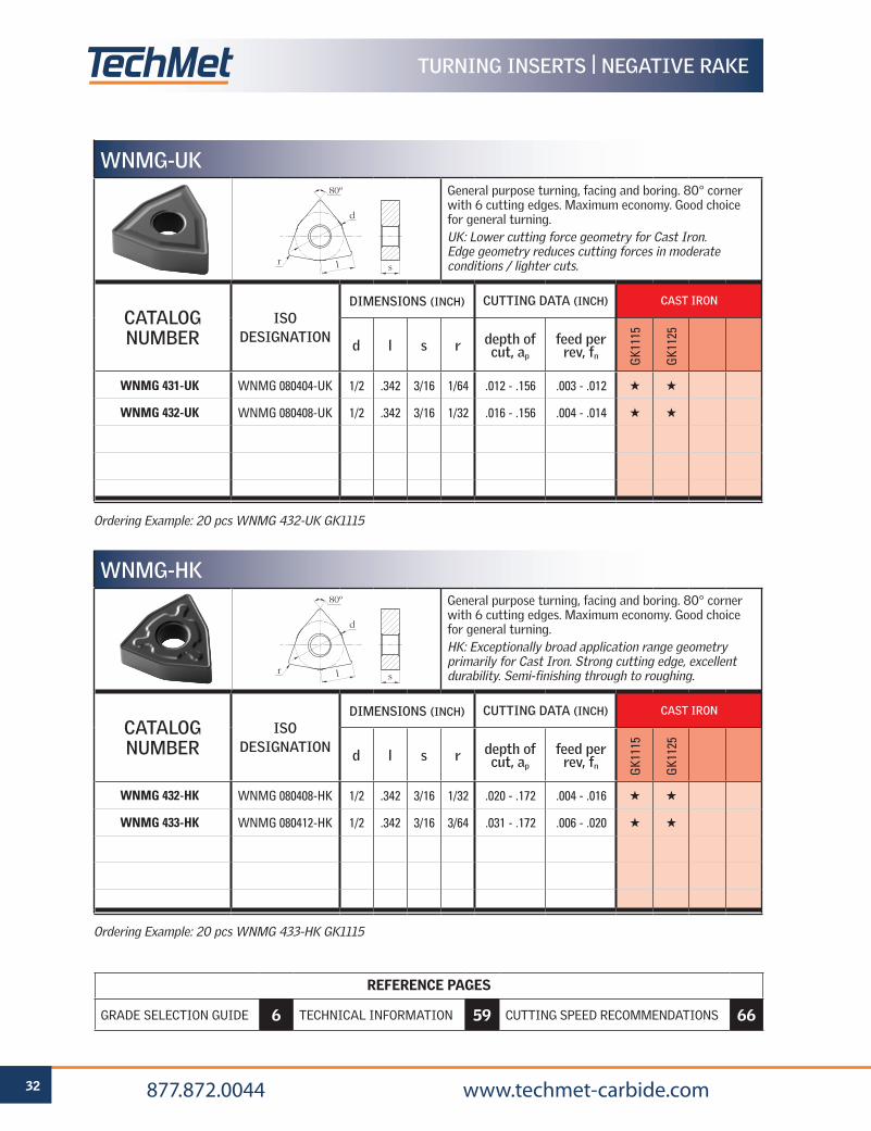
Ordering Example: 20 pcs WNMG 432-UK GK1115
Ordering Example: 20 pcs WNMG 433-HK GK1115
WNMG-UK
General purpose turning, facing and boring. 80° corner with 6 cutting edges. Maximum economy. Good choice for general turning.UK: Lower cutting force geometry for Cast Iron. Edge geometry reduces cutting forces in moderate conditions / lighter cuts.
CATALOG NUMBER
ISO DESIGNATION
DIMENSIONS (INCH) CUTTING DATA (INCH) CAST IRON
d l s r depth of cut, ap
feed per rev, fn G
K111
5
GK1
125
WNMG 431-UK WNMG 080404-UK 1/2 .342 3/16 1/64 .012 - .156 .003 - .012 H H
WNMG 432-UK WNMG 080408-UK 1/2 .342 3/16 1/32 .016 - .156 .004 - .014 H H
WNMG-HK
General purpose turning, facing and boring. 80° corner with 6 cutting edges. Maximum economy. Good choice for general turning.HK: Exceptionally broad application range geometry primarily for Cast Iron. Strong cutting edge, excellent durability. Semi-finishing through to roughing.
CATALOG NUMBER
ISO DESIGNATION
DIMENSIONS (INCH) CUTTING DATA (INCH) CAST IRON
d l s r depth of cut, ap
feed per rev, fn G
K111
5
GK1
125
WNMG 432-HK WNMG 080408-HK 1/2 .342 3/16 1/32 .020 - .172 .004 - .016 H H
WNMG 433-HK WNMG 080412-HK 1/2 .342 3/16 3/64 .031 - .172 .006 - .020 H H
d
sr
80º
l
d
sr
80º
l
TURNING INSERTS | NEGATIVE RAKE
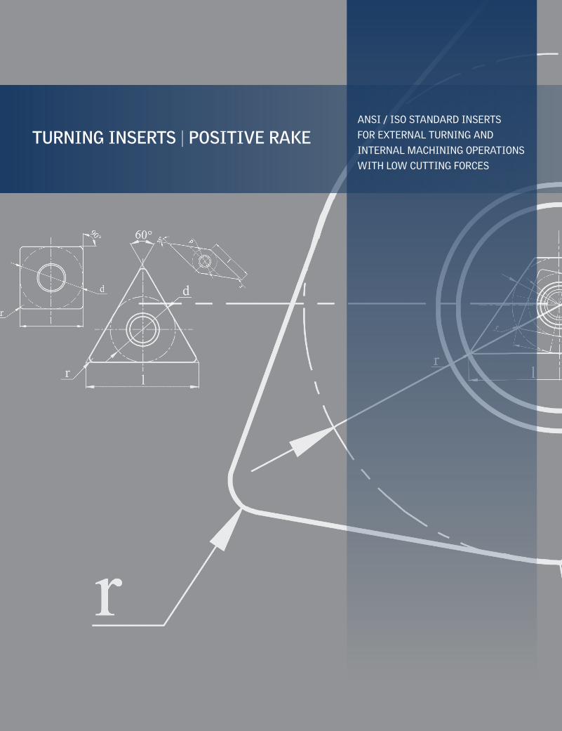
TURNING INSERTS | POSITIVE RAKEANSI / ISO STANDARD INSERTS
FOR EXTERNAL TURNING AND
INTERNAL MACHINING OPERATIONS
WITH LOW CUTTING FORCES
34 877.872.0044 www.techmet-carbide.com
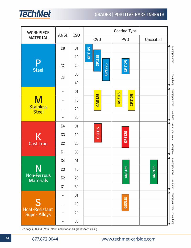
GRADES | POSITIVE RAKE INSERTS
WORKPIECEMATERIAL
ANSI ISOCoating Type
CVD PVD Uncoated
C8 01
10
20
30
40
– 01
– 10
– 20
– 30
C4 01
C3 10
C2 20
C1 30
C4 01
C3 10
C2 20
C1 30
– 01
– 10
– 20
– 30
GP1
115
GP1
225P
SteelC7
C6
GM
1125
GS3
115
toug
hnes
s
wea
r re
sist
ance
toug
hnes
s
wea
r re
sist
ance
toug
hnes
s
wea
r re
sist
ance
toug
hnes
s
wea
r re
sist
ance
toug
hnes
s
wea
r re
sist
ance
GS3
115
GN
9125
MStainless
Steel
SHeat-ResistantSuper Alloys
NNon-Ferrous
Materials
KCast Iron G
P312
5
GK
1115
See pages 68 and 69 for more information on grades for turning.
GP3
125
GP3
125
GP1
105
GN
3125
35 877.872.0044 www.techmet-carbide.com
CHIPBREAKERS | POSITIVE RAKE INSERTS
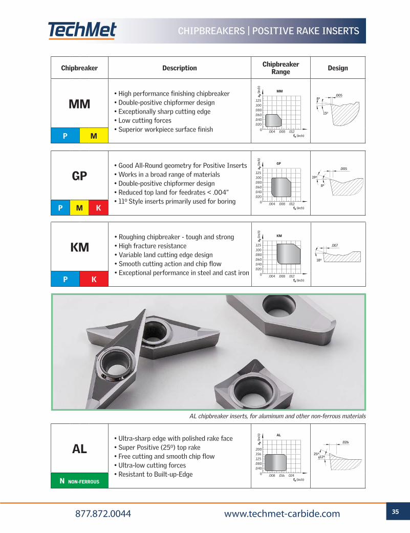
Chipbreaker Description Chipbreaker Range Design
MM• High performance finishing chipbreaker• Double-positive chipformer design• Exceptionally sharp cutting edge• Low cutting forces• Superior workpiece surface finish
P M
GP• Good All-Round geometry for Positive Inserts• Works in a broad range of materials• Double-positive chipformer design• Reduced top land for feedrates < .004”• 11o Style inserts primarily used for boring
P M K
AL• Ultra-sharp edge with polished rake face• Super Positive (25o) top rake• Free cutting and smooth chip flow• Ultra-low cutting forces• Resistant to Built-up-Edge
N NON-FERROUS
AL
.008 .016 .024 fn (inch)
.200
.156
.125
.080
.040
0
a p (i
nch)
MM
.004 .008 .012 fn (inch)
.125
.100
.080
.060
.040
.020
0
a p (i
nch)
GP
.004 .008 .012 fn (inch)
.125
.100
.080
.060
.040
.020
0
a p (i
nch)
.026 .005
.008
25o 15o
12o
.005
8o
19o
19o
5o or 7o
.005
8o
19o 15.5o
.004
23o
.007
15o
.012
16o
.015
20o
.005
15o
8o
.026 .005
.008
25o 15o
12o
.005
8o
19o
19o
5o or 7o
.005
8o
19o 15.5o
.004
23o
.007
15o
.012
16o
.015
20o
.005
15o
8o
.026 .005
.008
25o 15o
12o
.005
8o
19o
19o
5o or 7o
.005
8o
19o 15.5o
.004
23o
.007
15o
.012
16o
.015
20o
.005
15o
8o
AL chipbreaker inserts, for aluminum and other non-ferrous materials
KM• Roughing chipbreaker - tough and strong• High fracture resistance• Variable land cutting edge design• Smooth cutting action and chip flow• Exceptional performance in steel and cast iron
P K
KM
.004 .008 .012 fn (inch)
.125
.100
.080
.060
.040
.020
0
a p (i
nch)
18o
.007
REFERENCE PAGES
GRADE SELECTION GUIDE 6 TECHNICAL INFORMATION 59 CUTTING SPEED RECOMMENDATIONS 66
36 877.872.0044 www.techmet-carbide.com
REFERENCE PAGES
GRADE SELECTION GUIDE 34 TECHNICAL INFORMATION 59 CUTTING SPEED RECOMMENDATIONS 66
TURNING INSERTS | POSITIVE RAKE
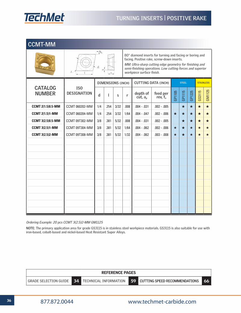
Ordering Example: 20 pcs CCMT 3(2.5)2-MM GM1125
NOTE: The primary application area for grade GS3115 is in stainless steel workpiece materials. GS3115 is also suitable for use with iron-based, cobalt-based and nickel-based Heat Resistant Super Alloys.
CCMT-MM
80° diamond inserts for turning and facing or boring and facing. Positive rake, screw-down inserts.
MM: Ultra-sharp cutting edge geometry for finishing and semi-finishing operations. Low cutting forces and superior workpiece surface finish.
CATALOG NUMBER
ISO DESIGNATION
DIMENSIONS (INCH) CUTTING DATA (INCH) STEEL STAINLESS
d l s r depth of cut, ap
feed per rev, fn
GP1
105
GP1
115
GP1
225
GS3
115
GM
1125
CCMT 2(1.5)0.5-MM CCMT 060202-MM 1/4 .254 3/32 .008 .004 - .031 .002 - .005 H H H H
CCMT 2(1.5)1-MM CCMT 060204-MM 1/4 .254 3/32 1/64 .004 - .047 .002 - .006 H H H H H
CCMT 3(2.5)0.5-MM CCMT 09T302-MM 3/8 .381 5/32 .008 .004 - .031 .002 - .005 H H H H
CCMT 3(2.5)1-MM CCMT 09T304-MM 3/8 .381 5/32 1/64 .004 - .062 .002 - .006 H H H H H
CCMT 3(2.5)2-MM CCMT 09T308-MM 3/8 .381 5/32 1/32 .004 - .062 .003 - .008 H H H H H
7°d
l sr
80º
REFERENCE PAGES
GRADE SELECTION GUIDE 6 TECHNICAL INFORMATION 59 CUTTING SPEED RECOMMENDATIONS 66
37 877.872.0044 www.techmet-carbide.com
REFERENCE PAGES
GRADE SELECTION GUIDE 34 TECHNICAL INFORMATION 59 CUTTING SPEED RECOMMENDATIONS 66
TURNING INSERTS | POSITIVE RAKE
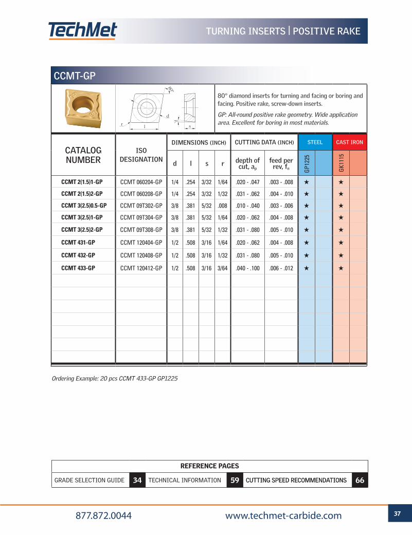
Ordering Example: 20 pcs CCMT 433-GP GP1225
CCMT-GP
80° diamond inserts for turning and facing or boring and facing. Positive rake, screw-down inserts.
GP: All-round positive rake geometry. Wide application area. Excellent for boring in most materials.
CATALOG NUMBER
ISO DESIGNATION
DIMENSIONS (INCH) CUTTING DATA (INCH) STEEL CAST IRON
d l s r depth of cut, ap
feed per rev, fn G
P122
5
GK1
115
CCMT 2(1.5)1-GP CCMT 060204-GP 1/4 .254 3/32 1/64 .020 - .047 .003 - .008 H H
CCMT 2(1.5)2-GP CCMT 060208-GP 1/4 .254 3/32 1/32 .031 - .062 .004 - .010 H H
CCMT 3(2.5)0.5-GP CCMT 09T302-GP 3/8 .381 5/32 .008 .010 - .040 .003 - .006 H H
CCMT 3(2.5)1-GP CCMT 09T304-GP 3/8 .381 5/32 1/64 .020 - .062 .004 - .008 H H
CCMT 3(2.5)2-GP CCMT 09T308-GP 3/8 .381 5/32 1/32 .031 - .080 .005 - .010 H H
CCMT 431-GP CCMT 120404-GP 1/2 .508 3/16 1/64 .020 - .062 .004 - .008 H H
CCMT 432-GP CCMT 120408-GP 1/2 .508 3/16 1/32 .031 - .080 .005 - .010 H H
CCMT 433-GP CCMT 120412-GP 1/2 .508 3/16 3/64 .040 - .100 .006 - .012 H H
7°d
l sr
80º
REFERENCE PAGES
GRADE SELECTION GUIDE 6 TECHNICAL INFORMATION 59 CUTTING SPEED RECOMMENDATIONS 66
38 877.872.0044 www.techmet-carbide.com
REFERENCE PAGES
GRADE SELECTION GUIDE 34 TECHNICAL INFORMATION 59 CUTTING SPEED RECOMMENDATIONS 66
TURNING INSERTS | POSITIVE RAKE
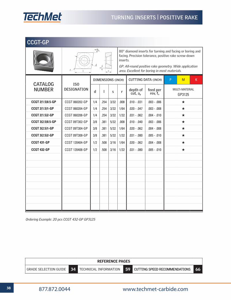
CCGT-GP
80° diamond inserts for turning and facing or boring and facing. Precision tolerance, positive rake screw-down inserts.
GP: All-round positive rake geometry. Wide application area. Excellent for boring in most materials.
CATALOG NUMBER
ISO DESIGNATION
DIMENSIONS (INCH) CUTTING DATA (INCH) P M K
d l s r depth of cut, ap
feed per rev, fn
MULTI-MATERIAL
GP3125
CCGT 2(1.5)0.5-GP CCGT 060202-GP 1/4 .254 3/32 .008 .010 - .031 .003 - .006 H
CCGT 2(1.5)1-GP CCGT 060204-GP 1/4 .254 3/32 1/64 .020 - .047 .003 - .008 H
CCGT 2(1.5)2-GP CCGT 060208-GP 1/4 .254 3/32 1/32 .031 - .062 .004 - .010 H
CCGT 3(2.5)0.5-GP CCGT 09T302-GP 3/8 .381 5/32 .008 .010 - .040 .003 - .006 H
CCGT 3(2.5)1-GP CCGT 09T304-GP 3/8 .381 5/32 1/64 .020 - .062 .004 - .008 H
CCGT 3(2.5)2-GP CCGT 09T308-GP 3/8 .381 5/32 1/32 .031 - .080 .005 - .010 H
CCGT 431-GP CCGT 120404-GP 1/2 .508 3/16 1/64 .020 - .062 .004 - .008 H
CCGT 432-GP CCGT 120408-GP 1/2 .508 3/16 1/32 .031 - .080 .005 - .010 H
7°d
l sr
80º
Ordering Example: 20 pcs CCGT 432-GP GP3125
REFERENCE PAGES
GRADE SELECTION GUIDE 6 TECHNICAL INFORMATION 59 CUTTING SPEED RECOMMENDATIONS 66
39 877.872.0044 www.techmet-carbide.com
REFERENCE PAGES
GRADE SELECTION GUIDE 34 TECHNICAL INFORMATION 59 CUTTING SPEED RECOMMENDATIONS 66
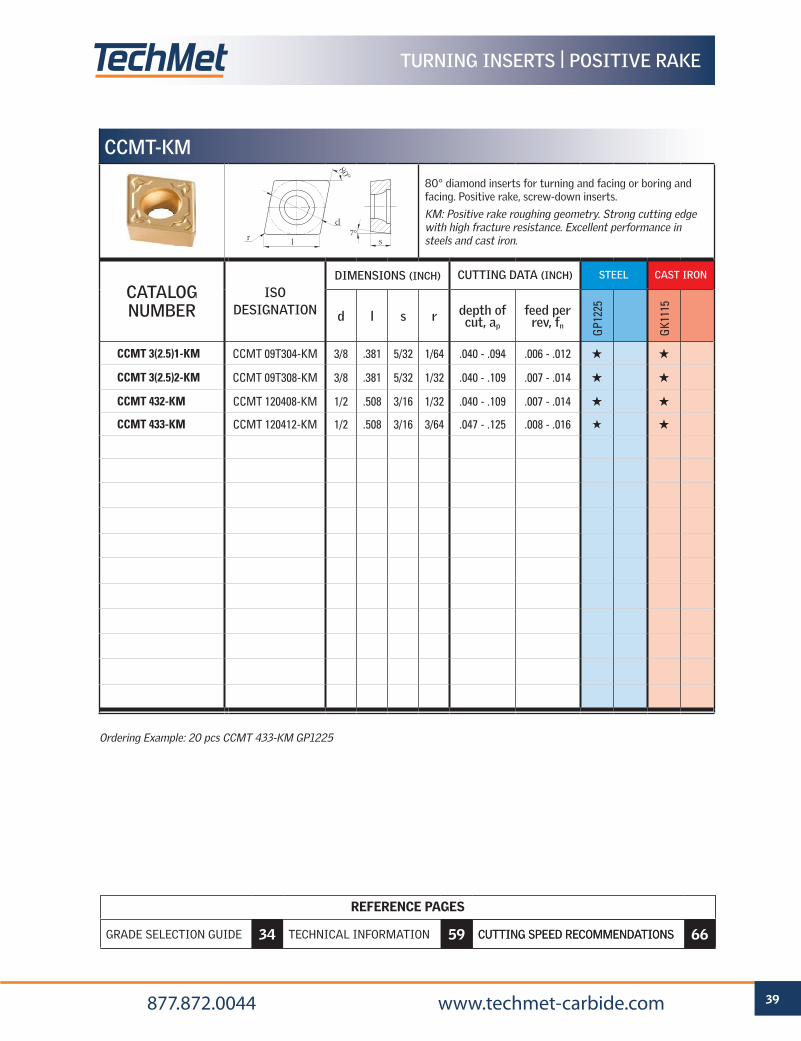
Ordering Example: 20 pcs CCMT 433-KM GP1225
TURNING INSERTS | POSITIVE RAKE
CCMT-KM
80° diamond inserts for turning and facing or boring and facing. Positive rake, screw-down inserts.
KM: Positive rake roughing geometry. Strong cutting edge with high fracture resistance. Excellent performance in steels and cast iron.
CATALOG NUMBER
ISO DESIGNATION
DIMENSIONS (INCH) CUTTING DATA (INCH) STEEL CAST IRON
d l s r depth of cut, ap
feed per rev, fn
GP1
225
GK1
115
CCMT 3(2.5)1-KM CCMT 09T304-KM 3/8 .381 5/32 1/64 .040 - .094 .006 - .012 H H
CCMT 3(2.5)2-KM CCMT 09T308-KM 3/8 .381 5/32 1/32 .040 - .109 .007 - .014 H H
CCMT 432-KM CCMT 120408-KM 1/2 .508 3/16 1/32 .040 - .109 .007 - .014 H H
CCMT 433-KM CCMT 120412-KM 1/2 .508 3/16 3/64 .047 - .125 .008 - .016 H H
7°d
l sr
80º
REFERENCE PAGES
GRADE SELECTION GUIDE 6 TECHNICAL INFORMATION 59 CUTTING SPEED RECOMMENDATIONS 66
40 877.872.0044 www.techmet-carbide.com
REFERENCE PAGES
GRADE SELECTION GUIDE 34 TECHNICAL INFORMATION 59 CUTTING SPEED RECOMMENDATIONS 66
TURNING INSERTS | POSITIVE RAKE
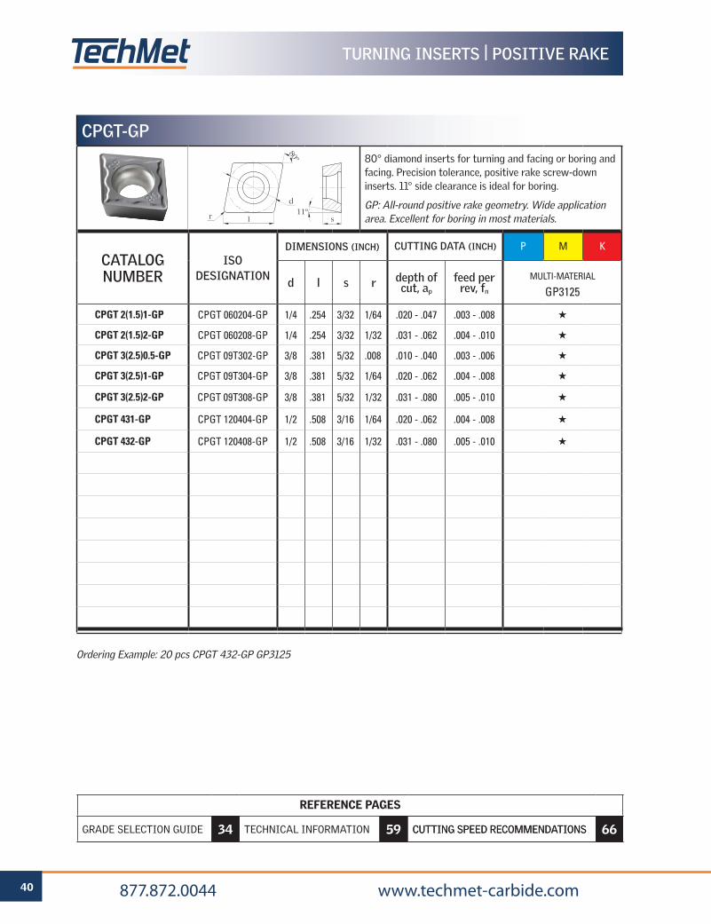
Ordering Example: 20 pcs CPGT 432-GP GP3125
CPGT-GP
80° diamond inserts for turning and facing or boring and facing. Precision tolerance, positive rake screw-down inserts. 11° side clearance is ideal for boring.
GP: All-round positive rake geometry. Wide application area. Excellent for boring in most materials.
CATALOG NUMBER
ISO DESIGNATION
DIMENSIONS (INCH) CUTTING DATA (INCH) P M K
d l s r depth of cut, ap
feed per rev, fn
MULTI-MATERIAL
GP3125
CPGT 2(1.5)1-GP CPGT 060204-GP 1/4 .254 3/32 1/64 .020 - .047 .003 - .008 H
CPGT 2(1.5)2-GP CPGT 060208-GP 1/4 .254 3/32 1/32 .031 - .062 .004 - .010 H
CPGT 3(2.5)0.5-GP CPGT 09T302-GP 3/8 .381 5/32 .008 .010 - .040 .003 - .006 H
CPGT 3(2.5)1-GP CPGT 09T304-GP 3/8 .381 5/32 1/64 .020 - .062 .004 - .008 H
CPGT 3(2.5)2-GP CPGT 09T308-GP 3/8 .381 5/32 1/32 .031 - .080 .005 - .010 H
CPGT 431-GP CPGT 120404-GP 1/2 .508 3/16 1/64 .020 - .062 .004 - .008 H
CPGT 432-GP CPGT 120408-GP 1/2 .508 3/16 1/32 .031 - .080 .005 - .010 H
d
l sr
80º
11º
REFERENCE PAGES
GRADE SELECTION GUIDE 6 TECHNICAL INFORMATION 59 CUTTING SPEED RECOMMENDATIONS 66
41 877.872.0044 www.techmet-carbide.com
REFERENCE PAGES
GRADE SELECTION GUIDE 34 TECHNICAL INFORMATION 59 CUTTING SPEED RECOMMENDATIONS 66
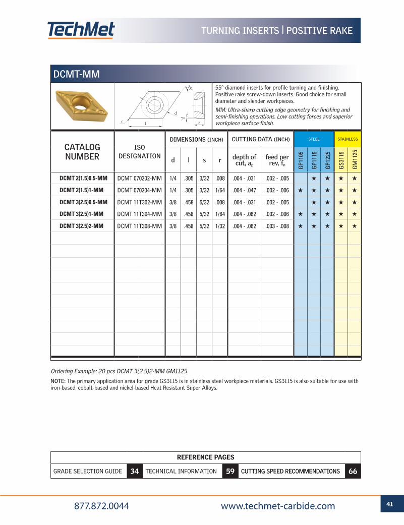
Ordering Example: 20 pcs DCMT 3(2.5)2-MM GM1125
NOTE: The primary application area for grade GS3115 is in stainless steel workpiece materials. GS3115 is also suitable for use with iron-based, cobalt-based and nickel-based Heat Resistant Super Alloys.
TURNING INSERTS | POSITIVE RAKE
DCMT-MM55° diamond inserts for profile turning and finishing. Positive rake screw-down inserts. Good choice for small diameter and slender workpieces.
MM: Ultra-sharp cutting edge geometry for finishing and semi-finishing operations. Low cutting forces and superior workpiece surface finish.
CATALOG NUMBER
ISO DESIGNATION
DIMENSIONS (INCH) CUTTING DATA (INCH) STEEL STAINLESS
d l s r depth of cut, ap
feed per rev, fn G
P110
5
GP1
115
GP1
225
GS3
115
GM
1125
DCMT 2(1.5)0.5-MM DCMT 070202-MM 1/4 .305 3/32 .008 .004 - .031 .002 - .005 H H H H
DCMT 2(1.5)1-MM DCMT 070204-MM 1/4 .305 3/32 1/64 .004 - .047 .002 - .006 H H H H H
DCMT 3(2.5)0.5-MM DCMT 11T302-MM 3/8 .458 5/32 .008 .004 - .031 .002 - .005 H H H H
DCMT 3(2.5)1-MM DCMT 11T304-MM 3/8 .458 5/32 1/64 .004 - .062 .002 - .006 H H H H H
DCMT 3(2.5)2-MM DCMT 11T308-MM 3/8 .458 5/32 1/32 .004 - .062 .003 - .008 H H H H H
d
l sr
55º
7º
REFERENCE PAGES
GRADE SELECTION GUIDE 6 TECHNICAL INFORMATION 59 CUTTING SPEED RECOMMENDATIONS 66
42 877.872.0044 www.techmet-carbide.com
REFERENCE PAGES
GRADE SELECTION GUIDE 34 TECHNICAL INFORMATION 59 CUTTING SPEED RECOMMENDATIONS 66
TURNING INSERTS | POSITIVE RAKE
Ordering Example: 20 pcs DCMT 433-GP GP1225
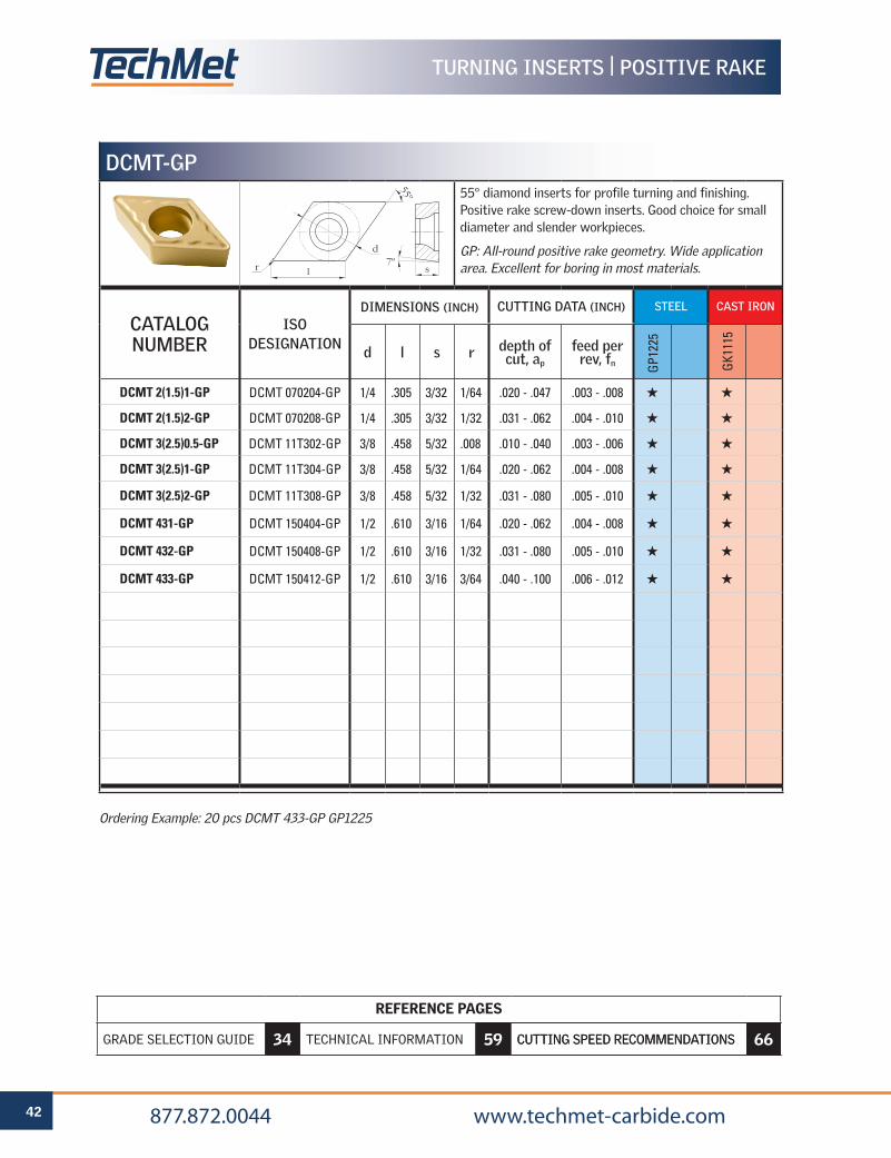
DCMT-GP
55° diamond inserts for profile turning and finishing. Positive rake screw-down inserts. Good choice for small diameter and slender workpieces.
GP: All-round positive rake geometry. Wide application area. Excellent for boring in most materials.
CATALOG NUMBER
ISO DESIGNATION
DIMENSIONS (INCH) CUTTING DATA (INCH) STEEL CAST IRON
d l s r depth of cut, ap
feed per rev, fn G
P122
5
GK1
115
DCMT 2(1.5)1-GP DCMT 070204-GP 1/4 .305 3/32 1/64 .020 - .047 .003 - .008 H H
DCMT 2(1.5)2-GP DCMT 070208-GP 1/4 .305 3/32 1/32 .031 - .062 .004 - .010 H H
DCMT 3(2.5)0.5-GP DCMT 11T302-GP 3/8 .458 5/32 .008 .010 - .040 .003 - .006 H H
DCMT 3(2.5)1-GP DCMT 11T304-GP 3/8 .458 5/32 1/64 .020 - .062 .004 - .008 H H
DCMT 3(2.5)2-GP DCMT 11T308-GP 3/8 .458 5/32 1/32 .031 - .080 .005 - .010 H H
DCMT 431-GP DCMT 150404-GP 1/2 .610 3/16 1/64 .020 - .062 .004 - .008 H H
DCMT 432-GP DCMT 150408-GP 1/2 .610 3/16 1/32 .031 - .080 .005 - .010 H H
DCMT 433-GP DCMT 150412-GP 1/2 .610 3/16 3/64 .040 - .100 .006 - .012 H H
d
l sr
55º
7º
REFERENCE PAGES
GRADE SELECTION GUIDE 6 TECHNICAL INFORMATION 59 CUTTING SPEED RECOMMENDATIONS 66
43 877.872.0044 www.techmet-carbide.com
REFERENCE PAGES
GRADE SELECTION GUIDE 34 TECHNICAL INFORMATION 59 CUTTING SPEED RECOMMENDATIONS 66
TURNING INSERTS | POSITIVE RAKE
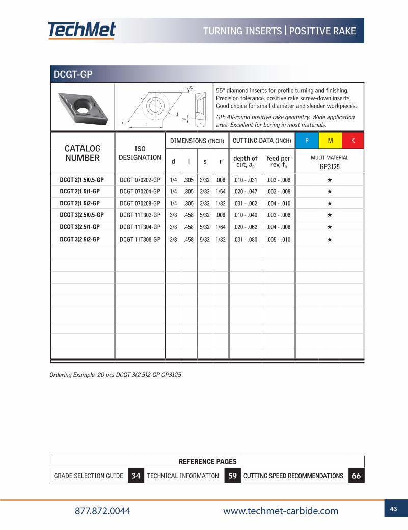
DCGT-GP
55° diamond inserts for profile turning and finishing. Precision tolerance, positive rake screw-down inserts. Good choice for small diameter and slender workpieces.
GP: All-round positive rake geometry. Wide application area. Excellent for boring in most materials.
CATALOG NUMBER
ISO DESIGNATION
DIMENSIONS (INCH) CUTTING DATA (INCH) P M K
d l s r depth of cut, ap
feed per rev, fn
MULTI-MATERIAL
GP3125
DCGT 2(1.5)0.5-GP DCGT 070202-GP 1/4 .305 3/32 .008 .010 - .031 .003 - .006 H
DCGT 2(1.5)1-GP DCGT 070204-GP 1/4 .305 3/32 1/64 .020 - .047 .003 - .008 H
DCGT 2(1.5)2-GP DCGT 070208-GP 1/4 .305 3/32 1/32 .031 - .062 .004 - .010 H
DCGT 3(2.5)0.5-GP DCGT 11T302-GP 3/8 .458 5/32 .008 .010 - .040 .003 - .006 H
DCGT 3(2.5)1-GP DCGT 11T304-GP 3/8 .458 5/32 1/64 .020 - .062 .004 - .008 H
DCGT 3(2.5)2-GP DCGT 11T308-GP 3/8 .458 5/32 1/32 .031 - .080 .005 - .010 H
d
l sr
55º
7º
Ordering Example: 20 pcs DCGT 3(2.5)2-GP GP3125
REFERENCE PAGES
GRADE SELECTION GUIDE 6 TECHNICAL INFORMATION 59 CUTTING SPEED RECOMMENDATIONS 66
44 877.872.0044 www.techmet-carbide.com
REFERENCE PAGES
GRADE SELECTION GUIDE 34 TECHNICAL INFORMATION 59 CUTTING SPEED RECOMMENDATIONS 66
TURNING INSERTS | POSITIVE RAKE
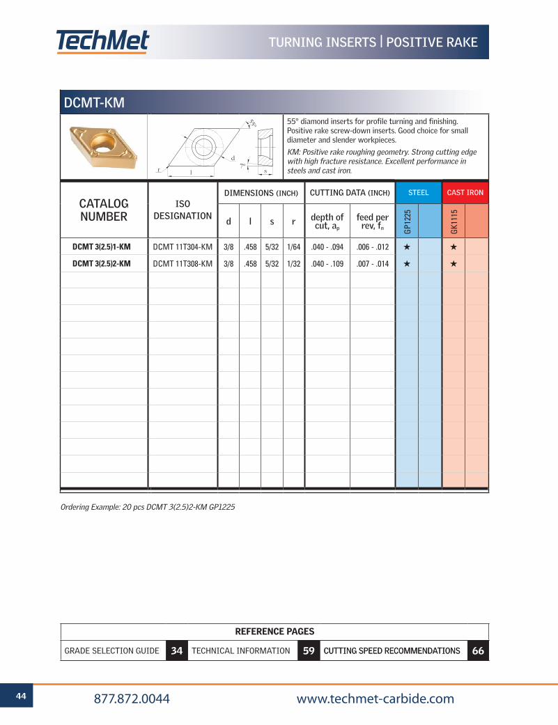
Ordering Example: 20 pcs DCMT 3(2.5)2-KM GP1225
DCMT-KM55° diamond inserts for profile turning and finishing. Positive rake screw-down inserts. Good choice for small diameter and slender workpieces.
KM: Positive rake roughing geometry. Strong cutting edge with high fracture resistance. Excellent performance in steels and cast iron.
CATALOG NUMBER
ISO DESIGNATION
DIMENSIONS (INCH) CUTTING DATA (INCH) STEEL CAST IRON
d l s r depth of cut, ap
feed per rev, fn G
P122
5
GK1
115
DCMT 3(2.5)1-KM DCMT 11T304-KM 3/8 .458 5/32 1/64 .040 - .094 .006 - .012 H H
DCMT 3(2.5)2-KM DCMT 11T308-KM 3/8 .458 5/32 1/32 .040 - .109 .007 - .014 H H
d
l sr
55º
7º
REFERENCE PAGES
GRADE SELECTION GUIDE 6 TECHNICAL INFORMATION 59 CUTTING SPEED RECOMMENDATIONS 66
45 877.872.0044 www.techmet-carbide.com
REFERENCE PAGES
GRADE SELECTION GUIDE 34 TECHNICAL INFORMATION 59 CUTTING SPEED RECOMMENDATIONS 66
TURNING INSERTS | POSITIVE RAKE
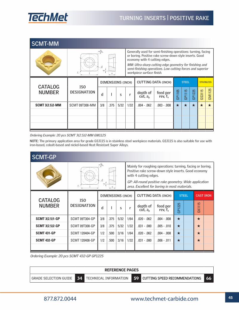
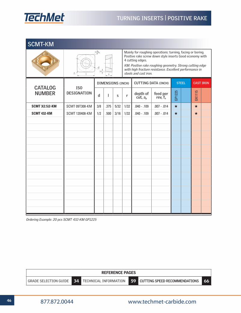
Ordering Example: 20 pcs SCMT 432-GP GP1225
SCMT-GPMainly for roughing operations: turning, facing or boring. Positive rake screw-down style inserts. Good economy with 4 cutting edges.
GP: All-round positive rake geometry. Wide application area. Excellent for boring in most materials.
CATALOG NUMBER
ISO DESIGNATION
DIMENSIONS (INCH) CUTTING DATA (INCH) STEEL CAST IRON
d l s r depth of cut, ap
feed per rev, fn G
P122
5
GK1
115
SCMT 3(2.5)1-GP SCMT 09T304-GP 3/8 .375 5/32 1/64 .020 - .062 .004 - .008 H H
SCMT 3(2.5)2-GP SCMT 09T308-GP 3/8 .375 5/32 1/32 .031 - .080 .005 - .010 H H
SCMT 431-GP SCMT 120404-GP 1/2 .500 3/16 1/64 .020 - .062 .004 - .008 H H
SCMT 432-GP SCMT 120408-GP 1/2 .500 3/16 1/32 .031 - .080 .006 - .011 H H
d
l sr
90º
7º
SCMT-MMGenerally used for semi-finishing operations: turning, facing or boring. Positive rake screw-down style inserts. Good economy with 4 cutting edges.
MM: Ultra-sharp cutting edge geometry for finishing and semi-finishing operations. Low cutting forces and superior workpiece surface finish.
CATALOG NUMBER
ISO DESIGNATION
DIMENSIONS (INCH) CUTTING DATA (INCH) STEEL STAINLESS
d l s r depth of cut, ap
feed per rev, fn G
P110
5
GP1
115
GP1
225
GS3
115
GM
1125
SCMT 3(2.5)2-MM SCMT 09T308-MM 3/8 .375 5/32 1/32 .004 - .062 .003 - .008 H H H H H
Ordering Example: 20 pcs SCMT 3(2.5)2-MM GM1125
NOTE: The primary application area for grade GS3115 is in stainless steel workpiece materials. GS3115 is also suitable for use with iron-based, cobalt-based and nickel-based Heat Resistant Super Alloys.
d
l sr
90º
7º
REFERENCE PAGES
GRADE SELECTION GUIDE 6 TECHNICAL INFORMATION 59 CUTTING SPEED RECOMMENDATIONS 66
46 877.872.0044 www.techmet-carbide.com
REFERENCE PAGES
GRADE SELECTION GUIDE 34 TECHNICAL INFORMATION 59 CUTTING SPEED RECOMMENDATIONS 66
TURNING INSERTS | POSITIVE RAKE
SCMT-KMMainly for roughing operations: turning, facing or boring. Positive rake screw down style inserts Good economy with 4 cutting edges.
KM: Positive rake roughing geometry. Strong cutting edge with high fracture resistance. Excellent performance in steels and cast iron.
CATALOG NUMBER
ISO DESIGNATION
DIMENSIONS (INCH) CUTTING DATA (INCH) STEEL CAST IRON
d l s r depth of cut, ap
feed per rev, fn G
P122
5
GK1
115
SCMT 3(2.5)2-KM SCMT 09T308-KM 3/8 .375 5/32 1/32 .040 - .109 .007 - .014 H H
SCMT 432-KM SCMT 120408-KM 1/2 .500 3/16 1/32 .040 - .109 .007 - .014 H H
Ordering Example: 20 pcs SCMT 432-KM GP1225
d
l sr
90º
7º
REFERENCE PAGES
GRADE SELECTION GUIDE 6 TECHNICAL INFORMATION 59 CUTTING SPEED RECOMMENDATIONS 66
47 877.872.0044 www.techmet-carbide.com
REFERENCE PAGES
GRADE SELECTION GUIDE 34 TECHNICAL INFORMATION 59 CUTTING SPEED RECOMMENDATIONS 66
TURNING INSERTS | POSITIVE RAKE
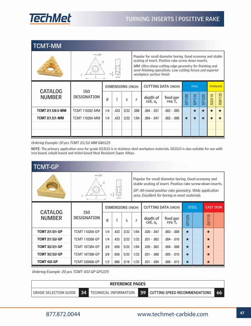
TCMT-MM
Popular for small diameter boring. Good economy and stable seating of insert. Positive rake screw down inserts.
MM: Ultra-sharp cutting edge geometry for finishing and semi-finishing operations. Low cutting forces and superior workpiece surface finish.
CATALOG NUMBER
ISO DESIGNATION
DIMENSIONS (INCH) CUTTING DATA (INCH) STEEL STAINLESS
d l s r depth of cut, ap
feed per rev, fn G
P110
5
GP1
115
GP1
225
GS3
115
GM
1125
TCMT 2(1.5)0.5-MM TCMT 110202-MM 1/4 .433 3/32 .008 .004 - .031 .002 - .005 H H H H
TCMT 2(1.5)1-MM TCMT 110204-MM 1/4 .433 3/32 1/64 .004 - .047 .002 - .006 H H H H H
Ordering Example: 20 pcs TCMT 2(1.5)1-MM GM1125
NOTE: The primary application area for grade GS3115 is in stainless steel workpiece materials. GS3115 is also suitable for use with iron-based, cobalt-based and nickel-based Heat Resistant Super Alloys.
d
srl
60º
7º
Ordering Example: 20 pcs TCMT 432-GP GP1225
TCMT-GP
Popular for small diameter boring. Good economy and stable seating of insert. Positive rake screw-down inserts.
GP: All-round positive rake geometry. Wide application area. Excellent for boring in most materials.
CATALOG NUMBER
ISO DESIGNATION
DIMENSIONS (INCH) CUTTING DATA (INCH) STEEL CAST IRON
d l s r depth of cut, ap
feed per rev, fn G
P122
5
GK1
115
TCMT 2(1.5)1-GP TCMT 110204-GP 1/4 .433 3/32 1/64 .020 - .047 .003 - .008 H H
TCMT 2(1.5)2-GP TCMT 110208-GP 1/4 .433 3/32 1/32 .031 - .062 .004 - .010 H H
TCMT 3(2.5)1-GP TCMT 16T304-GP 3/8 .650 5/32 1/64 .020 - .062 .004 - .008 H H
TCMT 3(2.5)2-GP TCMT 16T308-GP 3/8 .650 5/32 1/32 .031 - .080 .005 - .010 H H
TCMT 432-GP TCMT 220408-GP 1/2 .866 3/16 1/32 .031 - .094 .006 - .012 H H
d
srl
60º
7º
REFERENCE PAGES
GRADE SELECTION GUIDE 6 TECHNICAL INFORMATION 59 CUTTING SPEED RECOMMENDATIONS 66
48 877.872.0044 www.techmet-carbide.com
REFERENCE PAGES
GRADE SELECTION GUIDE 34 TECHNICAL INFORMATION 59 CUTTING SPEED RECOMMENDATIONS 66
TURNING INSERTS | POSITIVE RAKE
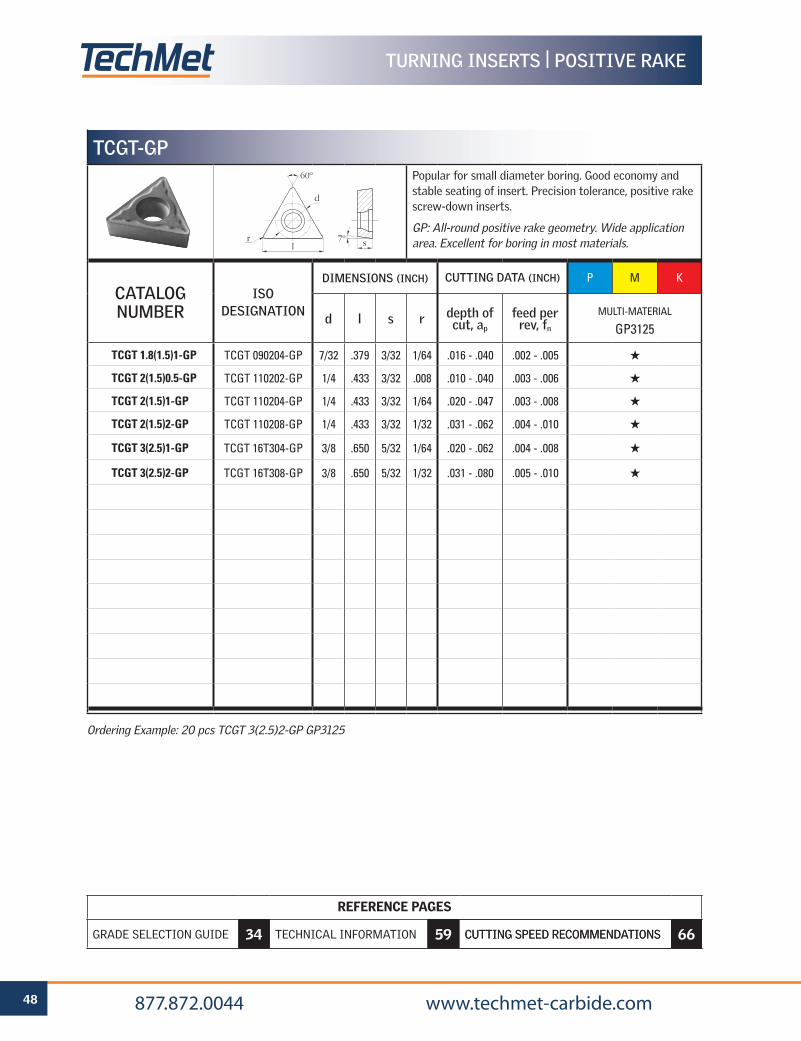
Ordering Example: 20 pcs TCGT 3(2.5)2-GP GP3125
TCGT-GP
Popular for small diameter boring. Good economy and stable seating of insert. Precision tolerance, positive rake screw-down inserts.
GP: All-round positive rake geometry. Wide application area. Excellent for boring in most materials.
CATALOG NUMBER
ISO DESIGNATION
DIMENSIONS (INCH) CUTTING DATA (INCH) P M K
d l s r depth of cut, ap
feed per rev, fn
MULTI-MATERIAL
GP3125
TCGT 1.8(1.5)1-GP TCGT 090204-GP 7/32 .379 3/32 1/64 .016 - .040 .002 - .005 H
TCGT 2(1.5)0.5-GP TCGT 110202-GP 1/4 .433 3/32 .008 .010 - .040 .003 - .006 H
TCGT 2(1.5)1-GP TCGT 110204-GP 1/4 .433 3/32 1/64 .020 - .047 .003 - .008 H
TCGT 2(1.5)2-GP TCGT 110208-GP 1/4 .433 3/32 1/32 .031 - .062 .004 - .010 H
TCGT 3(2.5)1-GP TCGT 16T304-GP 3/8 .650 5/32 1/64 .020 - .062 .004 - .008 H
TCGT 3(2.5)2-GP TCGT 16T308-GP 3/8 .650 5/32 1/32 .031 - .080 .005 - .010 H
d
srl
60º
7º
REFERENCE PAGES
GRADE SELECTION GUIDE 6 TECHNICAL INFORMATION 59 CUTTING SPEED RECOMMENDATIONS 66
49 877.872.0044 www.techmet-carbide.com
REFERENCE PAGES
GRADE SELECTION GUIDE 34 TECHNICAL INFORMATION 59 CUTTING SPEED RECOMMENDATIONS 66
TURNING INSERTS | POSITIVE RAKE
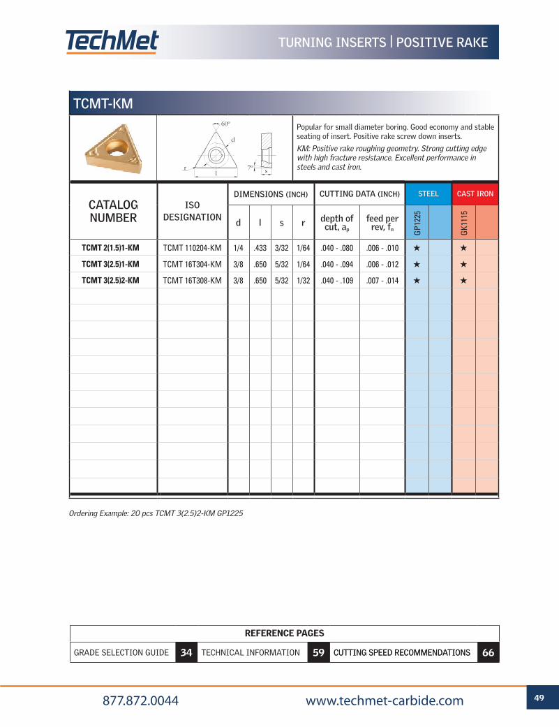
TCMT-KM
Popular for small diameter boring. Good economy and stable seating of insert. Positive rake screw down inserts.
KM: Positive rake roughing geometry. Strong cutting edge with high fracture resistance. Excellent performance in steels and cast iron.
CATALOG NUMBER
ISO DESIGNATION
DIMENSIONS (INCH) CUTTING DATA (INCH) STEEL CAST IRON
d l s r depth of cut, ap
feed per rev, fn G
P122
5
GK1
115
TCMT 2(1.5)1-KM TCMT 110204-KM 1/4 .433 3/32 1/64 .040 - .080 .006 - .010 H H
TCMT 3(2.5)1-KM TCMT 16T304-KM 3/8 .650 5/32 1/64 .040 - .094 .006 - .012 H H
TCMT 3(2.5)2-KM TCMT 16T308-KM 3/8 .650 5/32 1/32 .040 - .109 .007 - .014 H H
Ordering Example: 20 pcs TCMT 3(2.5)2-KM GP1225
d
srl
60º
7º
REFERENCE PAGES
GRADE SELECTION GUIDE 6 TECHNICAL INFORMATION 59 CUTTING SPEED RECOMMENDATIONS 66
50 877.872.0044 www.techmet-carbide.com
REFERENCE PAGES
GRADE SELECTION GUIDE 34 TECHNICAL INFORMATION 59 CUTTING SPEED RECOMMENDATIONS 66
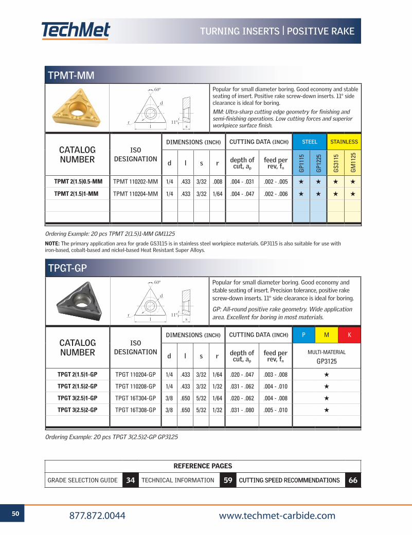
TURNING INSERTS | POSITIVE RAKE
TPMT-MMPopular for small diameter boring. Good economy and stable seating of insert. Positive rake screw-down inserts. 11° side clearance is ideal for boring.
MM: Ultra-sharp cutting edge geometry for finishing and semi-finishing operations. Low cutting forces and superior workpiece surface finish.
CATALOG NUMBER
ISO DESIGNATION
DIMENSIONS (INCH) CUTTING DATA (INCH) STEEL STAINLESS
d l s r depth of cut, ap
feed per rev, fn G
P111
5
GP1
225
GS3
115
GM
1125
TPMT 2(1.5)0.5-MM TPMT 110202-MM 1/4 .433 3/32 .008 .004 - .031 .002 - .005 H H H H
TPMT 2(1.5)1-MM TPMT 110204-MM 1/4 .433 3/32 1/64 .004 - .047 .002 - .006 H H H H
d
l sr
60º
11º
Ordering Example: 20 pcs TPGT 3(2.5)2-GP GP3125
Ordering Example: 20 pcs TPMT 2(1.5)1-MM GM1125
NOTE: The primary application area for grade GS3115 is in stainless steel workpiece materials. GP3115 is also suitable for use with iron-based, cobalt-based and nickel-based Heat Resistant Super Alloys.
TPGT-GP
Popular for small diameter boring. Good economy and stable seating of insert. Precision tolerance, positive rake screw-down inserts. 11° side clearance is ideal for boring.
GP: All-round positive rake geometry. Wide application area. Excellent for boring in most materials.
CATALOG NUMBER
ISO DESIGNATION
DIMENSIONS (INCH) CUTTING DATA (INCH) P M K
d l s r depth of cut, ap
feed per rev, fn
MULTI-MATERIAL
GP3125
TPGT 2(1.5)1-GP TPGT 110204-GP 1/4 .433 3/32 1/64 .020 - .047 .003 - .008 H
TPGT 2(1.5)2-GP TPGT 110208-GP 1/4 .433 3/32 1/32 .031 - .062 .004 - .010 H
TPGT 3(2.5)1-GP TPGT 16T304-GP 3/8 .650 5/32 1/64 .020 - .062 .004 - .008 H
TPGT 3(2.5)2-GP TPGT 16T308-GP 3/8 .650 5/32 1/32 .031 - .080 .005 - .010 H
d
l sr
60º
11º
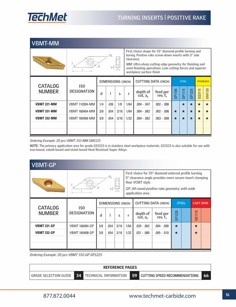
REFERENCE PAGES
GRADE SELECTION GUIDE 6 TECHNICAL INFORMATION 59 CUTTING SPEED RECOMMENDATIONS 66
51 877.872.0044 www.techmet-carbide.com
REFERENCE PAGES
GRADE SELECTION GUIDE 34 TECHNICAL INFORMATION 59 CUTTING SPEED RECOMMENDATIONS 66
TURNING INSERTS | POSITIVE RAKE
VBMT-MMFirst choice shape for 35° diamond profile turning and boring. Positive rake screw-down inserts with 5° side clearance.
MM: Ultra-sharp cutting edge geometry for finishing and semi-finishing operations. Low cutting forces and superior workpiece surface finish.
CATALOG NUMBER
ISO DESIGNATION
DIMENSIONS (INCH) CUTTING DATA (INCH) STEEL STAINLESS
d l s r depth of cut, ap
feed per rev, fn G
P110
5
GP1
115
GP1
225
GS3
115
GM
1125
VBMT 221-MM VBMT 110304-MM 1/4 .436 1/8 1/64 .004 - .047 .002 - .006 H H H H
VBMT 331-MM VBMT 160404-MM 3/8 .654 3/16 1/64 .004 - .062 .002 - .006 H H H H H
VBMT 332-MM VBMT 160408-MM 3/8 .654 3/16 1/32 .004 - .062 .003 - .008 H H H H H
Ordering Example: 20 pcs VBMT 332-MM GM1125
NOTE: The primary application area for grade GS3115 is in stainless steel workpiece materials. GS3115 is also suitable for use with iron-based, cobalt-based and nickel-based Heat Resistant Super Alloys.
d
l s
r
35º
5º
Ordering Example: 20 pcs VBMT 332-GP GP1225
VBMT-GP
First choice for 35° diamond external profile turning. 5° clearance angle provides more secure insert clamping than VCMT style.
GP: All-round positive rake geometry with wide application area.
CATALOG NUMBER
ISO DESIGNATION
DIMENSIONS (INCH) CUTTING DATA (INCH) STEEL CAST IRON
d l s r depth of cut, ap
feed per rev, fn G
P122
5
GK1
115
VBMT 331-GP VBMT 160404-GP 3/8 .654 3/16 1/64 .020 - .062 .004 - .008 H H
VBMT 332-GP VBMT 160408-GP 3/8 .654 3/16 1/32 .031 - .080 .005 - .010 H H
d
l s
r
35º
5º
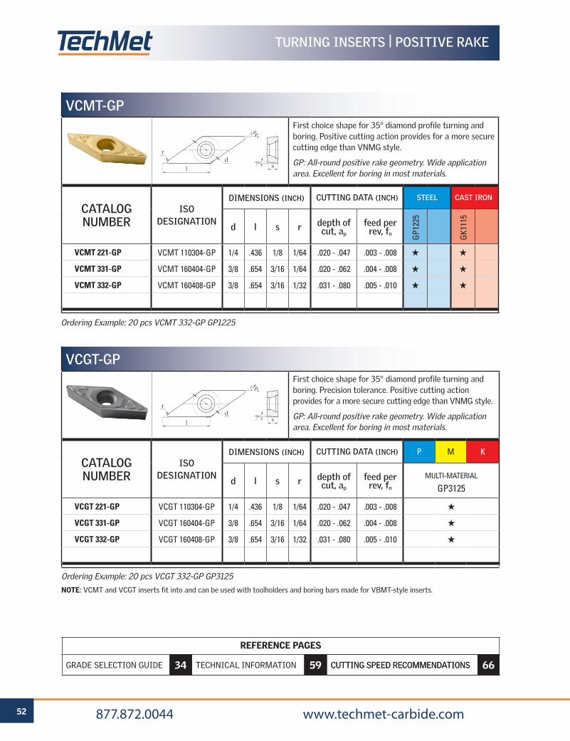
REFERENCE PAGES
GRADE SELECTION GUIDE 6 TECHNICAL INFORMATION 59 CUTTING SPEED RECOMMENDATIONS 66
52 877.872.0044 www.techmet-carbide.com
REFERENCE PAGES
GRADE SELECTION GUIDE 34 TECHNICAL INFORMATION 59 CUTTING SPEED RECOMMENDATIONS 66
TURNING INSERTS | POSITIVE RAKE
Ordering Example: 20 pcs VCMT 332-GP GP1225
VCMT-GP
First choice shape for 35° diamond profile turning and boring. Positive cutting action provides for a more secure cutting edge than VNMG style.
GP: All-round positive rake geometry. Wide application area. Excellent for boring in most materials.
CATALOG NUMBER
ISO DESIGNATION
DIMENSIONS (INCH) CUTTING DATA (INCH) STEEL CAST IRON
d l s r depth of cut, ap
feed per rev, fn G
P122
5
GK1
115
VCMT 221-GP VCMT 110304-GP 1/4 .436 1/8 1/64 .020 - .047 .003 - .008 H H
VCMT 331-GP VCMT 160404-GP 3/8 .654 3/16 1/64 .020 - .062 .004 - .008 H H
VCMT 332-GP VCMT 160408-GP 3/8 .654 3/16 1/32 .031 - .080 .005 - .010 H H
Ordering Example: 20 pcs VCGT 332-GP GP3125
NOTE: VCMT and VCGT inserts fit into and can be used with toolholders and boring bars made for VBMT-style inserts.
VCGT-GP
First choice shape for 35° diamond profile turning and boring. Precision tolerance. Positive cutting action provides for a more secure cutting edge than VNMG style.
GP: All-round positive rake geometry. Wide application area. Excellent for boring in most materials.
CATALOG NUMBER
ISO DESIGNATION
DIMENSIONS (INCH) CUTTING DATA (INCH) P M K
d l s r depth of cut, ap
feed per rev, fn
MULTI-MATERIAL
GP3125
VCGT 221-GP VCGT 110304-GP 1/4 .436 1/8 1/64 .020 - .047 .003 - .008 H
VCGT 331-GP VCGT 160404-GP 3/8 .654 3/16 1/64 .020 - .062 .004 - .008 H
VCGT 332-GP VCGT 160408-GP 3/8 .654 3/16 1/32 .031 - .080 .005 - .010 H
d
l s
r
35º
7º
d
l s
r
35º
7º
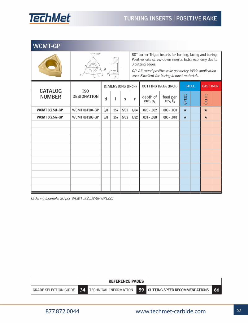
REFERENCE PAGES
GRADE SELECTION GUIDE 6 TECHNICAL INFORMATION 59 CUTTING SPEED RECOMMENDATIONS 66
53 877.872.0044 www.techmet-carbide.com
REFERENCE PAGES
GRADE SELECTION GUIDE 34 TECHNICAL INFORMATION 59 CUTTING SPEED RECOMMENDATIONS 66
TURNING INSERTS | POSITIVE RAKE
WCMT-GP
80° corner Trigon inserts for turning, facing and boring. Positive rake screw-down inserts. Extra economy due to 3 cutting edges.
GP: All-round positive rake geometry. Wide application area. Excellent for boring in most materials.
CATALOG NUMBER
ISO DESIGNATION
DIMENSIONS (INCH) CUTTING DATA (INCH) STEEL CAST IRON
d l s r depth of cut, ap
feed per rev, fn G
P122
5
GK1
115
WCMT 3(2.5)1-GP WCMT 06T304-GP 3/8 .257 5/32 1/64 .020 - .062 .003 - .008 H H
WCMT 3(2.5)2-GP WCMT 06T308-GP 3/8 .257 5/32 1/32 .031 - .080 .005 - .010 H H
Ordering Example: 20 pcs WCMT 3(2.5)2-GP GP1225
d
l sr
80º
7º

REFERENCE PAGES
GRADE SELECTION GUIDE 6 TECHNICAL INFORMATION 59 CUTTING SPEED RECOMMENDATIONS 66
54 877.872.0044 www.techmet-carbide.com
REFERENCE PAGES
GRADE SELECTION GUIDE 34 TECHNICAL INFORMATION 59 CUTTING SPEED RECOMMENDATIONS 66
TURNING INSERTS | POSITIVE RAKE
CCGX-AL
Precision Ground, High Positive, polished 80° diamond inserts for turning, boring and facing of Aluminum, non-ferrous materials and non-metallics.
AL: Extremely high 25° positive rake geometry. Super sharp edgeline with polished face for smooth chip flow.
CATALOG NUMBER
ISO DESIGNATION
DIMENSIONS (INCH) CUTTING DATA (INCH) NON-FERROUS
d l s r depth of cut, ap
feed per rev, fn G
N31
25
GN
9125
CCGX 2(1.5)0.5-AL CCGX 060202-AL 1/4 .254 3/32 .008 .010 - .047 .002 - .008 H H
CCGX 2(1.5)1-AL CCGX 060204-AL 1/4 .254 3/32 1/64 .016 - .062 .004 - .010 H H
CCGX 2(1.5)2-AL CCGX 060208-AL 1/4 .254 3/32 1/32 .020 - .062 .006 - .020 H H
CCGX 3(2.5)0.5-AL CCGX 09T302-AL 3/8 .381 5/32 .008 .010 - .094 .002 - .008 H H
CCGX 3(2.5)1-AL CCGX 09T304-AL 3/8 .381 5/32 1/64 .016 - .125 .004 - .010 H H
CCGX 3(2.5)2-AL CCGX 09T308-AL 3/8 .381 5/32 1/32 .020 - .125 .006 - .020 H H
CCGX 430.5-AL CCGX 120402-AL 1/2 .508 3/16 .008 .010 - .125 .002 - .008 H H
CCGX 431-AL CCGX 120404-AL 1/2 .508 3/16 1/64 .016 - .187 .004 - .010 H H
CCGX 432-AL CCGX 120408-AL 1/2 .508 3/16 1/32 .020 - .187 .006 - .020 H H
Ordering Example: 20 pcs CCGX 432-AL GN9125
7°d
l sr
80º
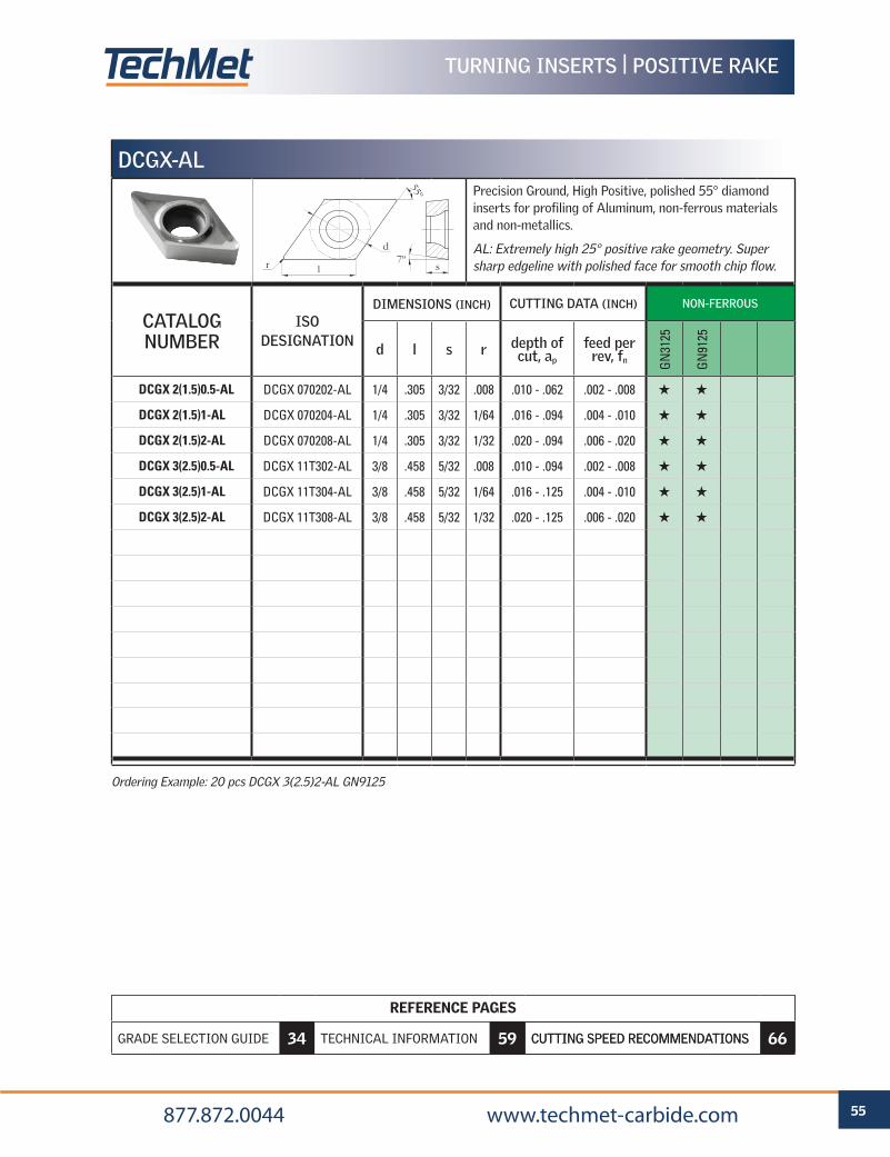
REFERENCE PAGES
GRADE SELECTION GUIDE 6 TECHNICAL INFORMATION 59 CUTTING SPEED RECOMMENDATIONS 66
55 877.872.0044 www.techmet-carbide.com
REFERENCE PAGES
GRADE SELECTION GUIDE 34 TECHNICAL INFORMATION 59 CUTTING SPEED RECOMMENDATIONS 66
TURNING INSERTS | POSITIVE RAKE
DCGX-AL
Precision Ground, High Positive, polished 55° diamond inserts for profiling of Aluminum, non-ferrous materials and non-metallics.
AL: Extremely high 25° positive rake geometry. Super sharp edgeline with polished face for smooth chip flow.
CATALOG NUMBER
ISO DESIGNATION
DIMENSIONS (INCH) CUTTING DATA (INCH) NON-FERROUS
d l s r depth of cut, ap
feed per rev, fn G
N31
25
GN
9125
DCGX 2(1.5)0.5-AL DCGX 070202-AL 1/4 .305 3/32 .008 .010 - .062 .002 - .008 H H
DCGX 2(1.5)1-AL DCGX 070204-AL 1/4 .305 3/32 1/64 .016 - .094 .004 - .010 H H
DCGX 2(1.5)2-AL DCGX 070208-AL 1/4 .305 3/32 1/32 .020 - .094 .006 - .020 H H
DCGX 3(2.5)0.5-AL DCGX 11T302-AL 3/8 .458 5/32 .008 .010 - .094 .002 - .008 H H
DCGX 3(2.5)1-AL DCGX 11T304-AL 3/8 .458 5/32 1/64 .016 - .125 .004 - .010 H H
DCGX 3(2.5)2-AL DCGX 11T308-AL 3/8 .458 5/32 1/32 .020 - .125 .006 - .020 H H
Ordering Example: 20 pcs DCGX 3(2.5)2-AL GN9125
d
l sr
55º
7º
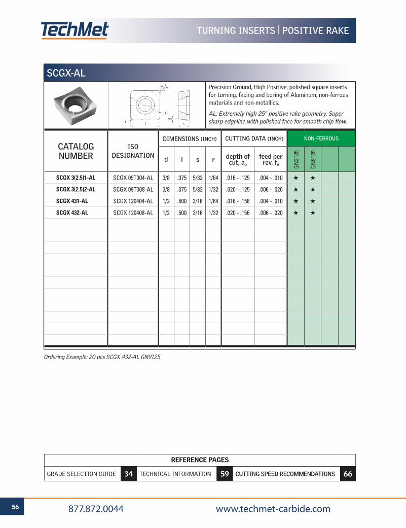
REFERENCE PAGES
GRADE SELECTION GUIDE 6 TECHNICAL INFORMATION 59 CUTTING SPEED RECOMMENDATIONS 66
56 877.872.0044 www.techmet-carbide.com
REFERENCE PAGES
GRADE SELECTION GUIDE 34 TECHNICAL INFORMATION 59 CUTTING SPEED RECOMMENDATIONS 66
TURNING INSERTS | POSITIVE RAKE
SCGX-AL
Precision Ground, High Positive, polished square inserts for turning, facing and boring of Aluminum, non-ferrous materials and non-metallics.
AL: Extremely high 25° positive rake geometry. Super sharp edgeline with polished face for smooth chip flow.
CATALOG NUMBER
ISO DESIGNATION
DIMENSIONS (INCH) CUTTING DATA (INCH) NON-FERROUS
d l s r depth of cut, ap
feed per rev, fn G
N31
25
GN
9125
SCGX 3(2.5)1-AL SCGX 09T304-AL 3/8 .375 5/32 1/64 .016 - .125 .004 - .010 H H
SCGX 3(2.5)2-AL SCGX 09T308-AL 3/8 .375 5/32 1/32 .020 - .125 .006 - .020 H H
SCGX 431-AL SCGX 120404-AL 1/2 .500 3/16 1/64 .016 - .156 .004 - .010 H H
SCGX 432-AL SCGX 120408-AL 1/2 .500 3/16 1/32 .020 - .156 .006 - .020 H H
Ordering Example: 20 pcs SCGX 432-AL GN9125
d
l sr
90º
7º
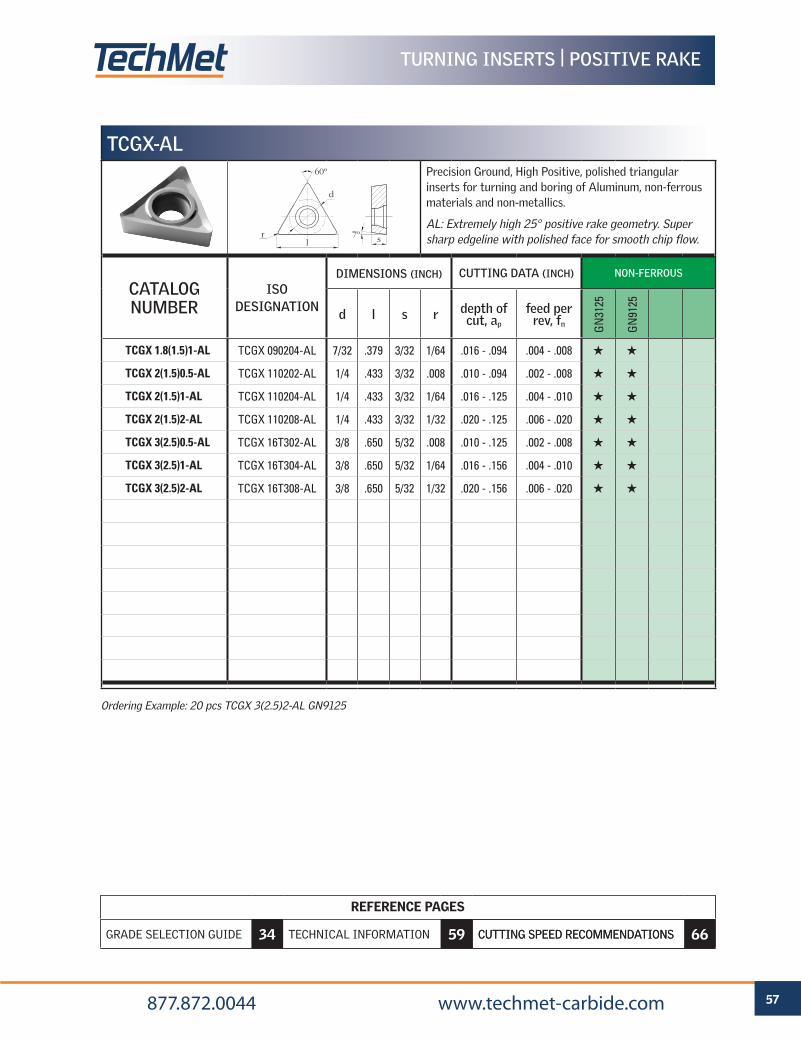
REFERENCE PAGES
GRADE SELECTION GUIDE 6 TECHNICAL INFORMATION 59 CUTTING SPEED RECOMMENDATIONS 66
57 877.872.0044 www.techmet-carbide.com
REFERENCE PAGES
GRADE SELECTION GUIDE 34 TECHNICAL INFORMATION 59 CUTTING SPEED RECOMMENDATIONS 66
TURNING INSERTS | POSITIVE RAKE
TCGX-AL
Precision Ground, High Positive, polished triangular inserts for turning and boring of Aluminum, non-ferrous materials and non-metallics.
AL: Extremely high 25° positive rake geometry. Super sharp edgeline with polished face for smooth chip flow.
CATALOG NUMBER
ISO DESIGNATION
DIMENSIONS (INCH) CUTTING DATA (INCH) NON-FERROUS
d l s r depth of cut, ap
feed per rev, fn G
N31
25
GN
9125
TCGX 1.8(1.5)1-AL TCGX 090204-AL 7/32 .379 3/32 1/64 .016 - .094 .004 - .008 H H
TCGX 2(1.5)0.5-AL TCGX 110202-AL 1/4 .433 3/32 .008 .010 - .094 .002 - .008 H H
TCGX 2(1.5)1-AL TCGX 110204-AL 1/4 .433 3/32 1/64 .016 - .125 .004 - .010 H H
TCGX 2(1.5)2-AL TCGX 110208-AL 1/4 .433 3/32 1/32 .020 - .125 .006 - .020 H H
TCGX 3(2.5)0.5-AL TCGX 16T302-AL 3/8 .650 5/32 .008 .010 - .125 .002 - .008 H H
TCGX 3(2.5)1-AL TCGX 16T304-AL 3/8 .650 5/32 1/64 .016 - .156 .004 - .010 H H
TCGX 3(2.5)2-AL TCGX 16T308-AL 3/8 .650 5/32 1/32 .020 - .156 .006 - .020 H H
Ordering Example: 20 pcs TCGX 3(2.5)2-AL GN9125
d
srl
60º
7º
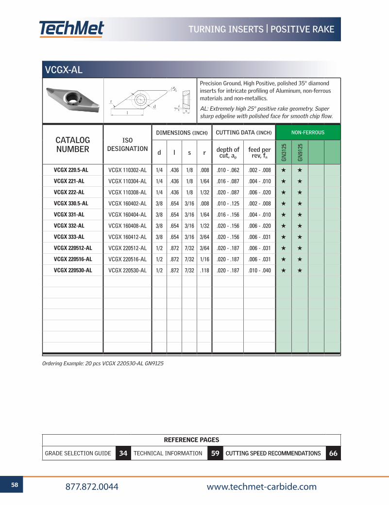
REFERENCE PAGES
GRADE SELECTION GUIDE 6 TECHNICAL INFORMATION 59 CUTTING SPEED RECOMMENDATIONS 66
58 877.872.0044 www.techmet-carbide.com
REFERENCE PAGES
GRADE SELECTION GUIDE 34 TECHNICAL INFORMATION 59 CUTTING SPEED RECOMMENDATIONS 66
TURNING INSERTS | POSITIVE RAKE
VCGX-AL
Precision Ground, High Positive, polished 35° diamond inserts for intricate profiling of Aluminum, non-ferrous materials and non-metallics.
AL: Extremely high 25° positive rake geometry. Super sharp edgeline with polished face for smooth chip flow.
CATALOG NUMBER
ISO DESIGNATION
DIMENSIONS (INCH) CUTTING DATA (INCH) NON-FERROUS
d l s r depth of cut, ap
feed per rev, fn G
N31
25
GN
9125
VCGX 220.5-AL VCGX 110302-AL 1/4 .436 1/8 .008 .010 - .062 .002 - .008 H H
VCGX 221-AL VCGX 110304-AL 1/4 .436 1/8 1/64 .016 - .087 .004 - .010 H H
VCGX 222-AL VCGX 110308-AL 1/4 .436 1/8 1/32 .020 - .087 .006 - .020 H H
VCGX 330.5-AL VCGX 160402-AL 3/8 .654 3/16 .008 .010 - .125 .002 - .008 H H
VCGX 331-AL VCGX 160404-AL 3/8 .654 3/16 1/64 .016 - .156 .004 - .010 H H
VCGX 332-AL VCGX 160408-AL 3/8 .654 3/16 1/32 .020 - .156 .006 - .020 H H
VCGX 333-AL VCGX 160412-AL 3/8 .654 3/16 3/64 .020 - .156 .006 - .031 H H
VCGX 220512-AL VCGX 220512-AL 1/2 .872 7/32 3/64 .020 - .187 .006 - .031 H H
VCGX 220516-AL VCGX 220516-AL 1/2 .872 7/32 1/16 .020 - .187 .006 - .031 H H
VCGX 220530-AL VCGX 220530-AL 1/2 .872 7/32 .118 .020 - .187 .010 - .040 H H
Ordering Example: 20 pcs VCGX 220530-AL GN9125
d
l s
r
35º
7º
Code Keys 60
Formulas & Nomenclature 64
Surface Roughness 65
Cutting Speed Recommendations 66
Grades for Turning 68
Troubleshooting 70
TECHNICAL INFORMATIONTURNING
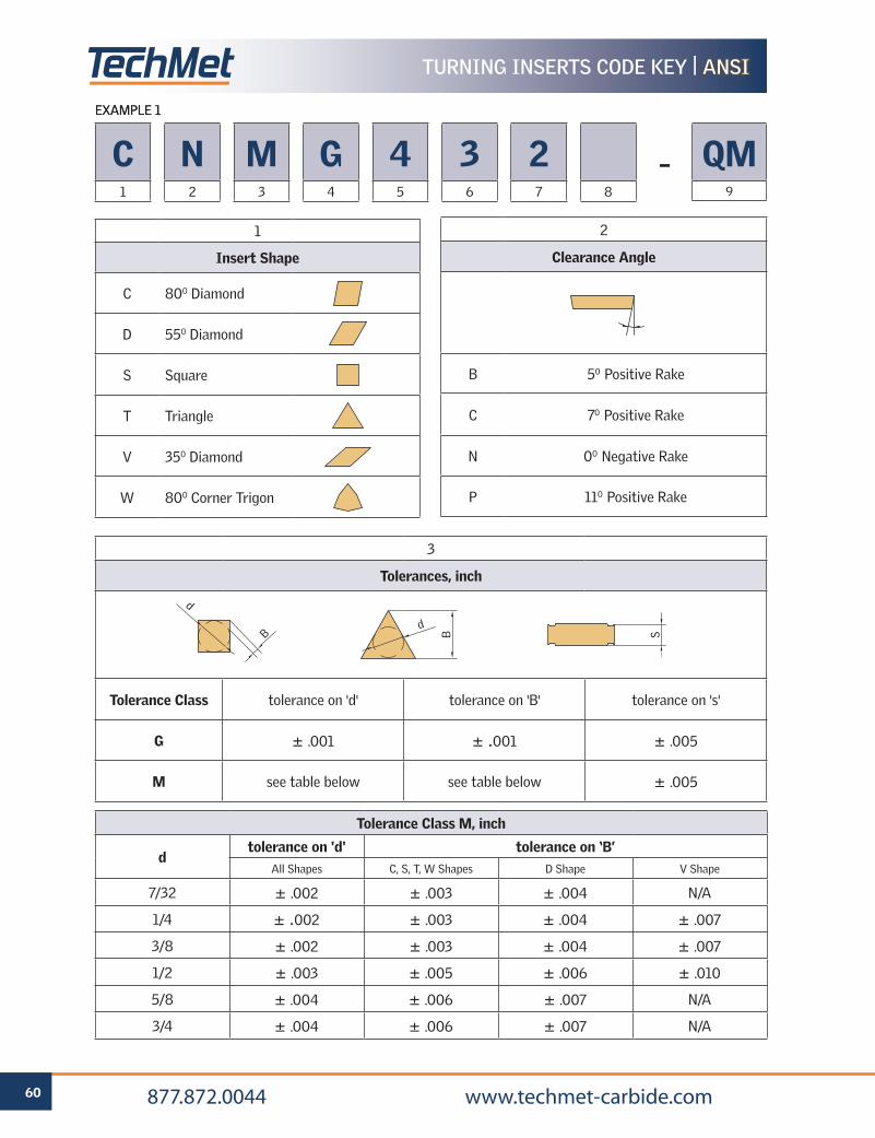
60 877.872.0044 www.techmet-carbide.com
TURNING INSERTS CODE KEY | ANSI ANSI
EXAMPLE 1
1
Insert Shape
C 800 Diamond
D 550 Diamond
S Square
T Triangle
V 350 Diamond
W 800 Corner Trigon
2
Clearance Angle
B 50 Positive Rake
C 70 Positive Rake
N 00 Negative Rake
P 110 Positive Rake
3
Tolerances, inch
Tolerance Class tolerance on 'd' tolerance on 'B' tolerance on 's'
G ± .001 ± .001 ± .005
M see table below see table below ± .005
Tolerance Class M, inch
dtolerance on 'd' tolerance on ‘B’
All Shapes C, S, T, W Shapes D Shape V Shape
7/32 ± .002 ± .003 ± .004 N/A
1/4 ± .002 ± .003 ± .004 ± .007
3/8 ± .002 ± .003 ± .004 ± .007
1/2 ± .003 ± .005 ± .006 ± .010
5/8 ± .004 ± .006 ± .007 N/A
3/4 ± .004 ± .006 ± .007 N/A
d
dB B S
C1
N2
M3
G4
45
36
27 8
QM9
–
EXAMPLE 1
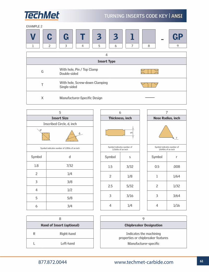
61 877.872.0044 www.techmet-carbide.com
TURNING INSERTS CODE KEY | ANSIANSI
6
Thickness, inch
Symbol indicates number of 1/16ths of an inch
Symbol s
1.5 3/32
2 1/8
2.5 5/32
3 3/16
4 1/4
5
Insert Size
Inscribed Circle, d, inch
Symbol indicates number of 1/8ths of an inch
Symbol d
1.8 7/32
2 1/4
3 3/8
4 1/2
5 5/8
6 3/4
7
Nose Radius, inch
Symbol indicates number of 1/64ths of an inch
Symbol r
0.5 .008
1 1/64
2 1/32
3 3/64
4 1/16
8
Hand of Insert (optional)
R Right-hand
L Left-hand
9
Chipbreaker Designation
Indicates the machining properties or chipbreaker features
Manufacturer-specific
4
Insert Type
GWith hole, Pin / Top Clamp Double-sided
TWith hole, Screw-down Clamping Single-sided
X Manufacturer-Specific Design
r
Sd
d
V1
C2
G3
T4
35
36
17 8
GP9
–
EXAMPLE 2
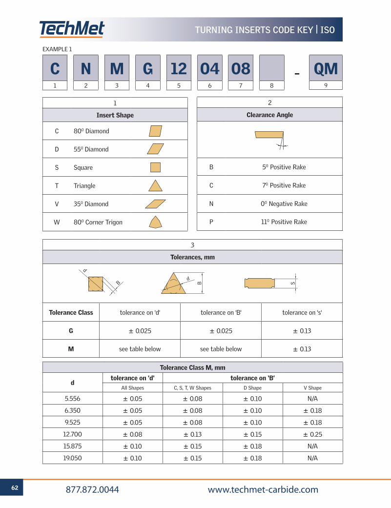
REFERENCE PAGES
GRADE SELECTION GUIDE 6 TECHNICAL INFORMATION 59 CUTTING SPEED RECOMMENDATIONS 66
62 877.872.0044 www.techmet-carbide.com
TURNING INSERTS CODE KEY | ISO
C1
N2
M3
G4
125
046
087 8
QM9
–
EXAMPLE 1
1
Insert Shape
C 800 Diamond
D 550 Diamond
S Square
T Triangle
V 350 Diamond
W 800 Corner Trigon
2
Clearance Angle
B 50 Positive Rake
C 70 Positive Rake
N 00 Negative Rake
P 110 Positive Rake
3
Tolerances, mm
Tolerance Class tolerance on 'd' tolerance on 'B' tolerance on 's'
G ± 0.025 ± 0.025 ± 0.13
M see table below see table below ± 0.13
Tolerance Class M, mm
dtolerance on 'd' tolerance on ‘B’
All Shapes C, S, T, W Shapes D Shape V Shape
5.556 ± 0.05 ± 0.08 ± 0.10 N/A
6.350 ± 0.05 ± 0.08 ± 0.10 ± 0.18
9.525 ± 0.05 ± 0.08 ± 0.10 ± 0.18
12.700 ± 0.08 ± 0.13 ± 0.15 ± 0.25
15.875 ± 0.10 ± 0.15 ± 0.18 N/A
19.050 ± 0.10 ± 0.15 ± 0.18 N/A
d
dB B S
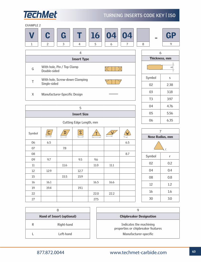
REFERENCE PAGES
GRADE SELECTION GUIDE 6 TECHNICAL INFORMATION 59 CUTTING SPEED RECOMMENDATIONS 66
63 877.872.0044 www.techmet-carbide.com
TURNING INSERTS CODE KEY | ISO
5
Insert Size
Cutting Edge Length, mm
Symbol
06 6.5 6.5
07 7.8
08 8.7
09 9.7 9.5 9.6
11 11.6 11.0 11.1
12 12.9 12.7
15 15.5 15.9
16 16.1 16.5 16.6
19 19.4 19.1
22 22.0 22.2
27 27.5
6
Thickness, mm
Symbol s
02 2.38
03 3.18
T3 3.97
04 4.76
05 5.56
06 6.35
7
Nose Radius, mm
Symbol r
02 0.2
04 0.4
08 0.8
12 1.2
16 1.6
30 3.0
8
Hand of Insert (optional)
R Right-hand
L Left-hand
9
Chipbreaker Designation
Indicates the machining properties or chipbreaker features
Manufacturer-specific
4
Insert Type
GWith hole, Pin / Top Clamp Double-sided
TWith hole, Screw-down Clamping Single-sided
X Manufacturer-Specific Design
V1
C2
G3
T4
165
046
047 8
GP9
–
EXAMPLE 2
S
r
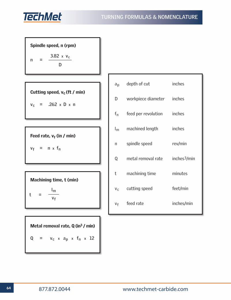
64 877.872.0044 www.techmet-carbide.com
TURNING FORMULAS & NOMENCLATURE
ap depth of cut inches
D workpiece diameter inches
fn feed per revolution inches
lm machined length inches
n spindle speed rev/min
Q metal removal rate inches3/min
t machining time minutes
vc cutting speed feet/min
vf feed rate inches/min
Cutting speed, vc (ft / min)
vc = .262 x D x n
Feed rate, vf (in / min)
vf = n x fn
Metal removal rate, Q (in3 / min)
Q = vc x ap x fn x 12
Spindle speed, n (rpm)
Machining time, t (min)
3.82 x vc
Dn =
lm
vft =
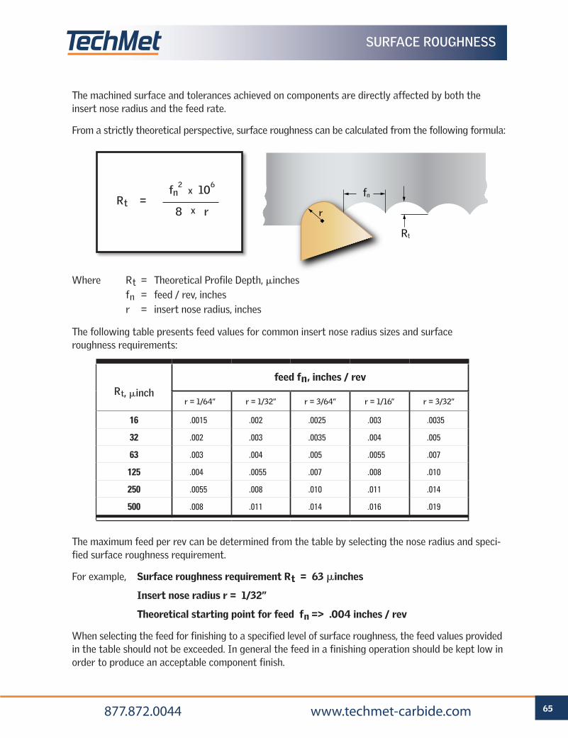
65 877.872.0044 www.techmet-carbide.com
Rt
fn
SURFACE ROUGHNESS
The maximum feed per rev can be determined from the table by selecting the nose radius and speci-fied surface roughness requirement.
For example, Surface roughness requirement Rt = 63 minches
Insert nose radius r = 1/32”
Theoretical starting point for feed fn => .004 inches / rev
When selecting the feed for finishing to a specified level of surface roughness, the feed values provided in the table should not be exceeded. In general the feed in a finishing operation should be kept low in order to produce an acceptable component finish.
Rt =
The machined surface and tolerances achieved on components are directly affected by both the insert nose radius and the feed rate.
From a strictly theoretical perspective, surface roughness can be calculated from the following formula:
The following table presents feed values for common insert nose radius sizes and surface roughness requirements:
Rt, minch
feed fn, inches / rev
r = 1/64” r = 1/32” r = 3/64” r = 1/16” r = 3/32”
16 .0015 .002 .0025 .003 .0035
32 .002 .003 .0035 .004 .005
63 .003 .004 .005 .0055 .007
125 .004 .0055 .007 .008 .010
250 .0055 .008 .010 .011 .014
500 .008 .011 .014 .016 .019
fn2 x 106
8 x r
Where Rt = Theoretical Profile Depth, minches fn = feed / rev, inches r = insert nose radius, inches
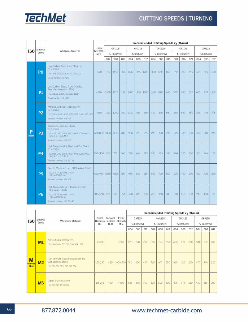
66 877.872.0044 www.techmet-carbide.com
CUTTING SPEEDS | TURNING
ISO Material Group
Workpiece MaterialTensile
Strength MPa
Recommended Starting Speeds vc (ft/min)
GP1105 GP1115 GP1225 GP1135 GP3125
fn (inch/rev) fn (inch/rev) fn (inch/rev) fn (inch/rev) fn (inch/rev)
.004 .008 .012 .004 .008 .012 .004 .008 .016 .004 .016 .024 .004 .008 .012
P Steel
PO
Low-Carbon Steels, Long Chipping (C < .25%)
Ex. A36, 1008, 1010, 1018, 1108, 1117
Brinell Hardness HB <125
<530 1760 1550 1370 1640 1445 1280 1400 1245 855 1215 790 655 655 525 400
P1
Low-Carbon Steels, Short Chipping, Free Machining (C < .25%)
Ex. 10L18, 1200 Series, 1213, 12L14
Brinell Hardness HB <125
<530 1500 1330 1120 1400 1245 1050 1180 1015 655 1015 590 525 600 475 360
P2
Medium- and High-Carbon Steels (C > .25%)
Ex. 1035, 1045, 10L45, 1080, 1137, 1144, 1525, 1572
Rockwell Hardness HRC <25
>530 1120 1050 950 1050 985 885 920 820 590 855 540 460 525 445 345
P3
Alloy Steels and Tool Steels (C > .25%)
Ex. P20, 1300, 2000, 3000, 4000, 5000, 8000, SAE A, D, H, O, S, M, T
Rockwell Hardness HRC <35
600-850 1020 850 700 950 790 655 790 720 490 625 445 330 400 300 245
P4
High-Strength Alloy Steels and Tool Steels(C > .25%)
Ex. P20, 1300, 2000, 3000, 4000, 5000, 8000, SAE A, D, H, O, S, M, T
Rockwell Hardness HRC 35 - 48
850-1400 850 700 560 790 655 525 590 525 330 460 300 230 310 245 180
P5
Ferritic, Martensitic and PH Stainless Steels
Ex. 13-8 PH, 15-5 PH, 17-4 PH, 400 and 500 Series
Rockwell Hardness HRC <35
600-900 1050 880 700 985 820 655 855 720 560 625 460 330 420 320 260
P6
High-Strength Ferritic, Martensitic andPH Stainless Steels
Ex. 13-8 PH, 15-5 PH, 17-4 PH, 400 and 500 Series
Rockwell Hardness HRC 35 - 48
900-1350 630 530 350 590 490 330 425 360 300 360 260 230 230 190 135
ISO Material Group
Workpiece MaterialBrinell
Hardness HB
Rockwell Hardness
HRC
Tensile Strength
MPa
Recommended Starting Speeds vc (ft/min)
GS3115 GM1125 GM3125 GP3125
fn (inch/rev) fn (inch/rev) fn (inch/rev) fn (inch/rev)
.004 .008 .012 .004 .008 .012 .004 .008 .012 .004 .008 .012
M Stainless
Steel
M1Austenitic Stainless Steels
Ex. 200 Series, 301, 302, 304, 304L, 309130-200 <600 820 670 490 850 750 650 620 470 290 520 380 240
M2High-Strength Austenitic Stainless and Cast Stainless Steels
Ex. 310, 316, 316L, 321, 347, 384
150-230 <25 600-800 740 600 440 760 670 580 560 420 260 470 340 220
M3Duplex Stainless Steels
Ex. 323, 329, F55, 2205135-275 <30 <800 655 535 390 670 600 520 495 375 230 420 310 200
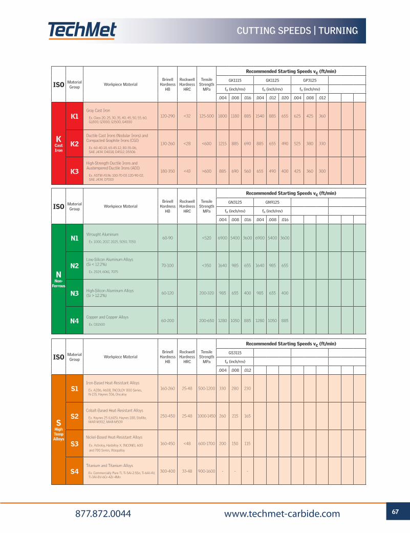
67 877.872.0044 www.techmet-carbide.com
CUTTING SPEEDS | TURNING
ISO Material Group
Workpiece MaterialBrinell
Hardness HB
Rockwell Hardness
HRC
Tensile Strength
MPa
Recommended Starting Speeds vc (ft/min)
GK1115 GK1125 GP3125
fn (inch/rev) fn (inch/rev) fn (inch/rev)
.004 .008 .016 .004 .012 .020 .004 .008 .012
K Cast Iron
K1Gray Cast Iron
Ex. Class 20, 25, 30, 35, 40, 45, 50, 55, 60, G1800, G3000, G3500, G4000
120-290 <32 125-500 1800 1180 885 1540 885 655 625 425 360
K2Ductile Cast Irons (Nodular Irons) and Compacted Graphite Irons (CGI)
Ex. 60-40-18, 65-45-12, 80-55-06, SAE J434: D4018, D4512, D5506
130-260 <28 <600 1215 885 690 885 655 490 525 380 330
K3High-Strength Ductile Irons and Austempered Ductile Irons (ADI)
Ex. ASTM A536: 100-70-03, 120-90-02, SAE J434: D7003
180-350 <43 >600 885 690 560 655 490 400 425 360 300
ISO Material Group
Workpiece MaterialBrinell
Hardness HB
Rockwell Hardness
HRC
Tensile Strength
MPa
Recommended Starting Speeds vc (ft/min)
GN3125 GN9125
fn (inch/rev) fn (inch/rev)
.004 .008 .016 .004 .008 .016
N Non-
Ferrous
N1Wrought Aluminum
Ex. 1000, 2017, 2025, 5050, 705060-90 <520 6900 5400 3600 6900 5400 3600
N2Low-Silicon Aluminum Alloys (Si < 12.2%)
Ex. 2024, 6061, 7075
70-100 <350 1640 985 655 1640 985 655
N3 High-Silicon Aluminum Alloys (Si > 12.2%)
60-120 200-320 985 655 400 985 655 400
N4Copper and Copper Alloys
Ex. C8150060-200 200-650 1280 1050 885 1280 1050 885
ISO Material Group
Workpiece MaterialBrinell
Hardness HB
Rockwell Hardness
HRC
Tensile Strength
MPa
Recommended Starting Speeds vc (ft/min)
GS3115
fn (inch/rev)
.004 .008 .012
S High Temp Alloys
S1Iron-Based Heat-Resistant Alloys
Ex. A286, A608, INCOLOY 800 Series, N-155, Haynes 556, Discaloy
160-260 25-48 500-1200 330 280 230
S2Cobalt-Based Heat-Resistant Alloys
Ex. Haynes 25 (L605), Haynes 188, Stellite, MAR-M302, MAR-M509
250-450 25-48 1000-1450 260 215 165
S3Nickel-Based Heat-Resistant Alloys
Ex. Astroloy, Hastelloy X, INCONEL 600
and 700 Series, Waspalloy
160-450 <48 600-1700 200 150 115
S4Titanium and Titanium Alloys
Ex. Commercially Pure Ti, Ti-5Al-2.5Sn, Ti-6Al-4V, Ti-3Al-8V-6Cr-4Zr-4Mo
300-400 33-48 900-1600 - - -
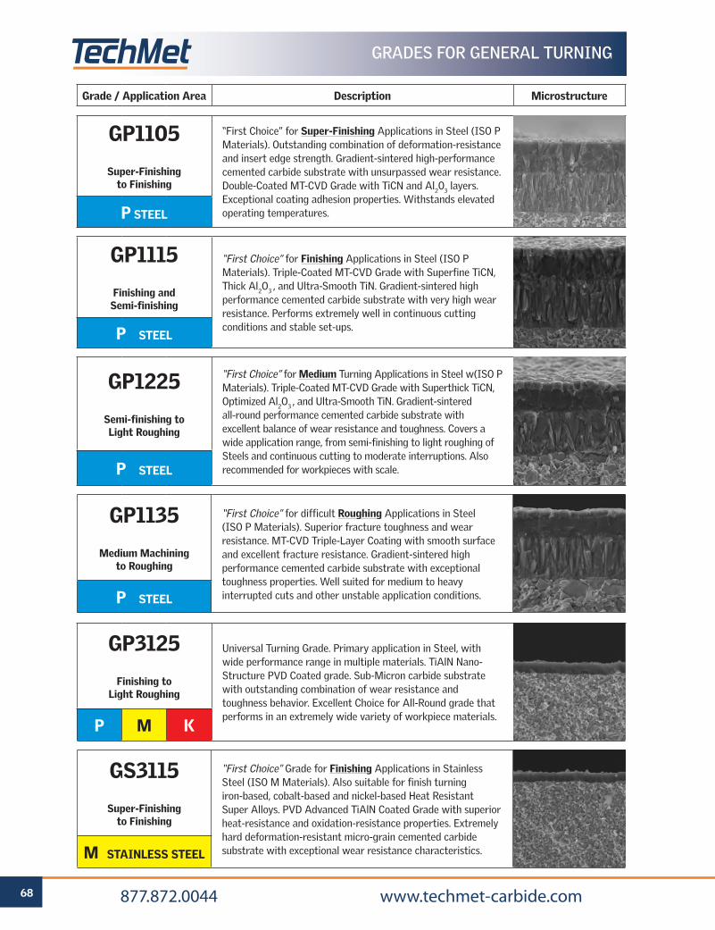
68 877.872.0044 www.techmet-carbide.com
Grade / Application Area Description Microstructure
GP1105
Super-Finishing to Finishing
“First Choice” for Super-Finishing Applications in Steel (ISO P Materials). Outstanding combination of deformation-resistance and insert edge strength. Gradient-sintered high-performance cemented carbide substrate with unsurpassed wear resistance. Double-Coated MT-CVD Grade with TiCN and Al203 layers. Exceptional coating adhesion properties. Withstands elevated operating temperatures. P STEEL
GP1115
Finishing and Semi-finishing
“First Choice” for Finishing Applications in Steel (ISO P Materials). Triple-Coated MT-CVD Grade with Superfine TiCN, Thick Al2O3 , and Ultra-Smooth TiN. Gradient-sintered high performance cemented carbide substrate with very high wear resistance. Performs extremely well in continuous cutting conditions and stable set-ups.P STEEL
GP1225
Semi-finishing to Light Roughing
“First Choice” for Medium Turning Applications in Steel w(ISO P Materials). Triple-Coated MT-CVD Grade with Superthick TiCN, Optimized Al2O3 , and Ultra-Smooth TiN. Gradient-sintered all-round performance cemented carbide substrate with excellent balance of wear resistance and toughness. Covers a wide application range, from semi-finishing to light roughing of Steels and continuous cutting to moderate interruptions. Also recommended for workpieces with scale.P STEEL
GP1135
Medium Machining to Roughing
“First Choice” for difficult Roughing Applications in Steel (ISO P Materials). Superior fracture toughness and wear resistance. MT-CVD Triple-Layer Coating with smooth surface and excellent fracture resistance. Gradient-sintered high performance cemented carbide substrate with exceptional toughness properties. Well suited for medium to heavy interrupted cuts and other unstable application conditions.P STEEL
GP3125
Finishing to Light Roughing
Universal Turning Grade. Primary application in Steel, with wide performance range in multiple materials. TiAlN Nano-Structure PVD Coated grade. Sub-Micron carbide substrate with outstanding combination of wear resistance and toughness behavior. Excellent Choice for All-Round grade that performs in an extremely wide variety of workpiece materials.
P M K
GS3115
Super-Finishing to Finishing
“First Choice” Grade for Finishing Applications in Stainless Steel (ISO M Materials). Also suitable for finish turning iron-based, cobalt-based and nickel-based Heat Resistant Super Alloys. PVD Advanced TiAlN Coated Grade with superior heat-resistance and oxidation-resistance properties. Extremely hard deformation-resistant micro-grain cemented carbide substrate with exceptional wear resistance characteristics.M STAINLESS STEEL
GRADES FOR GENERAL TURNING
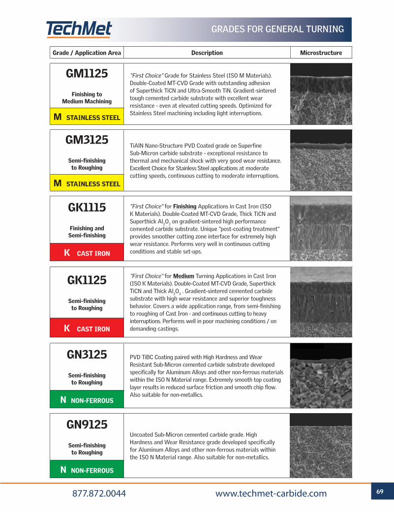
69 877.872.0044 www.techmet-carbide.com
Grade / Application Area Description Microstructure
GM1125
Finishing to Medium Machining
“First Choice” Grade for Stainless Steel (ISO M Materials). Double-Coated MT-CVD Grade with outstanding adhesion of Superthick TiCN and Ultra-Smooth TiN. Gradient-sintered tough cemented carbide substrate with excellent wear resistance - even at elevated cutting speeds. Optimized for Stainless Steel machining including light interruptions.M STAINLESS STEEL
GM3125
Semi-finishing to Roughing
TiAlN Nano-Structure PVD Coated grade on Superfine Sub-Micron carbide substrate - exceptional resistance to thermal and mechanical shock with very good wear resistance. Excellent Choice for Stainless Steel applications at moderate cutting speeds, continuous cutting to moderate interruptions.
M STAINLESS STEEL
GK1115
Finishing and Semi-finishing
“First Choice” for Finishing Applications in Cast Iron (ISO K Materials). Double-Coated MT-CVD Grade, Thick TiCN and Superthick Al2O3 on gradient-sintered high performance cemented carbide substrate. Unique “post-coating treatment” provides smoother cutting zone interface for extremely high wear resistance. Performs very well in continuous cutting conditions and stable set-ups.K CAST IRON
GK1125
Semi-finishing to Roughing
“First Choice” for Medium Turning Applications in Cast Iron (ISO K Materials). Double-Coated MT-CVD Grade, Superthick TiCN and Thick Al2O3 . Gradient-sintered cemented carbide substrate with high wear resistance and superior toughness behavior. Covers a wide application range, from semi-finishing to roughing of Cast Iron - and continuous cutting to heavy interruptions. Performs well in poor machining conditions / on demanding castings.K CAST IRON
GN3125
Semi-finishing to Roughing
PVD TiBC Coating paired with High Hardness and Wear Resistant Sub-Micron cemented carbide substrate developed specifically for Aluminum Alloys and other non-ferrous materials within the ISO N Material range. Extremely smooth top coating layer results in reduced surface friction and smooth chip flow. Also suitable for non-metallics.
N NON-FERROUS
GN9125
Semi-finishing to Roughing
Uncoated Sub-Micron cemented carbide grade. High Hardness and Wear Resistance grade developed specifically for Aluminum Alloys and other non-ferrous materials within the ISO N Material range. Also suitable for non-metallics.
N NON-FERROUS
GRADES FOR GENERAL TURNING
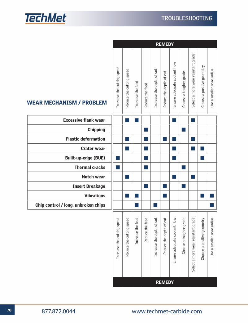
70 877.872.0044 www.techmet-carbide.com
r
E60°
TROUBLESHOOTING
REMEDY
Incr
ease
the
cut
ting
spe
ed
Red
uce
the
cutt
ing
spee
d
Incr
ease
the
fee
d
Red
uce
the
feed
Incr
ease
the
dep
th o
f cu
t
Red
uce
the
dept
h of
cut
Ensu
re a
dequ
ate
cool
ant
flow
Cho
ose
a to
ughe
r gr
ade
Sel
ect
a m
ore
wea
r re
sist
ant
grad
e
Cho
ose
a po
siti
ve g
eom
etry
Use
a s
mal
ler
nose
rad
ius
Incr
ease
the
cut
ting
spe
ed
Red
uce
the
cutt
ing
spee
d
Incr
ease
the
fee
d
Red
uce
the
feed
Incr
ease
the
dep
th o
f cu
t
Red
uce
the
dept
h of
cut
Ensu
re a
dequ
ate
cool
ant
flow
Cho
ose
a to
ughe
r gr
ade
Sel
ect
a m
ore
wea
r re
sist
ant
grad
e
Cho
ose
a po
siti
ve g
eom
etry
Use
a s
mal
ler
nose
rad
ius
REMEDY
■ ■ ■ ■
■ ■
■ ■ ■ ■ ■
■ ■ ■ ■ ■
■ ■ ■ ■
■ ■ ■
■ ■ ■
■ ■ ■
■ ■ ■ ■ ■
■ ■ ■
Excessive flank wear
Chipping
Plastic deformation
Crater wear
Built-up-edge (BUE)
Thermal cracks
Notch wear
Insert Breakage
Vibrations
Chip control / long, unbroken chips
WEAR MECHANISM / PROBLEM
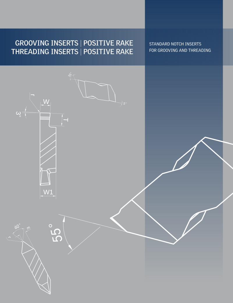
3°
r
T
W
W1
r
E60°
5°
55°
GROOVING INSERTS | POSITIVE RAKETHREADING INSERTS | POSITIVE RAKE
STANDARD NOTCH INSERTS
FOR GROOVING AND THREADING
55°
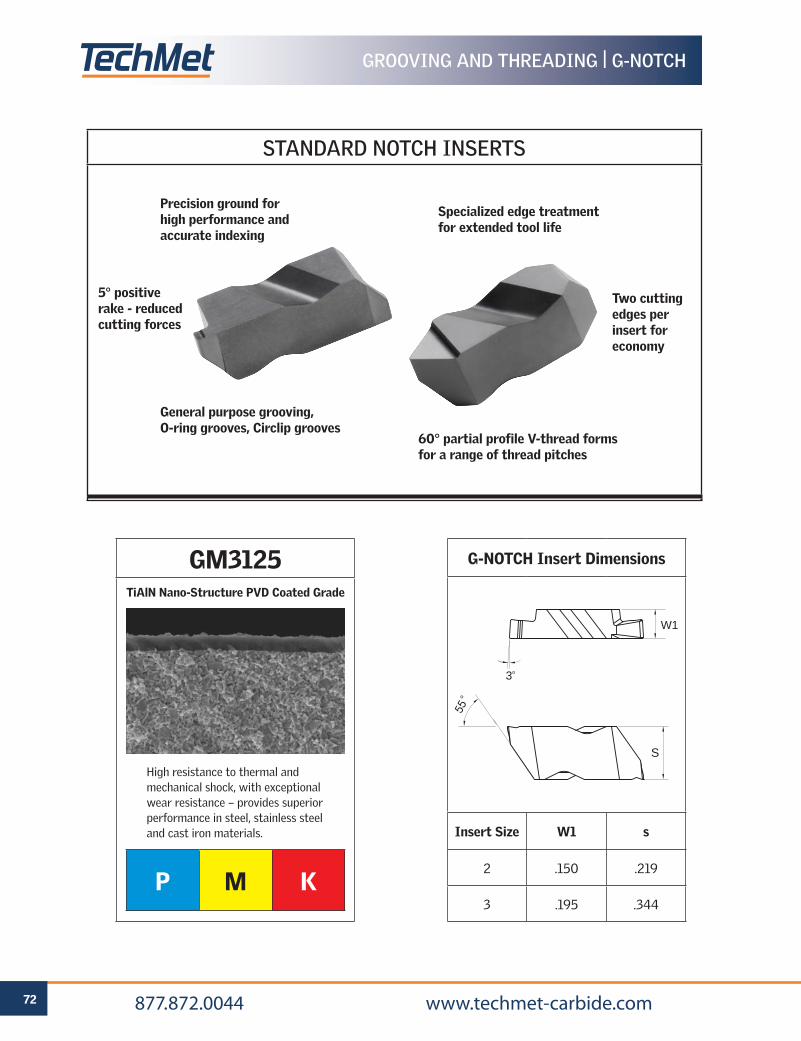
72 877.872.0044 www.techmet-carbide.com
STANDARD NOTCH INSERTS
GROOVING AND THREADING | G-NOTCH
G-NOTCH Insert Dimensions
Insert Size W1 s
2 .150 .219
3 .195 .344
3°
W1
S
55°
GM3125
P M K
High resistance to thermal and mechanical shock, with exceptional wear resistance – provides superior performance in steel, stainless steel and cast iron materials.
TiAlN Nano-Structure PVD Coated Grade
Precision ground for high performance and accurate indexing
5° positive rake - reduced cutting forces
Specialized edge treatment for extended tool life
Two cutting edges per insert for economy
General purpose grooving, O-ring grooves, Circlip grooves
60° partial profile V-thread forms for a range of thread pitches
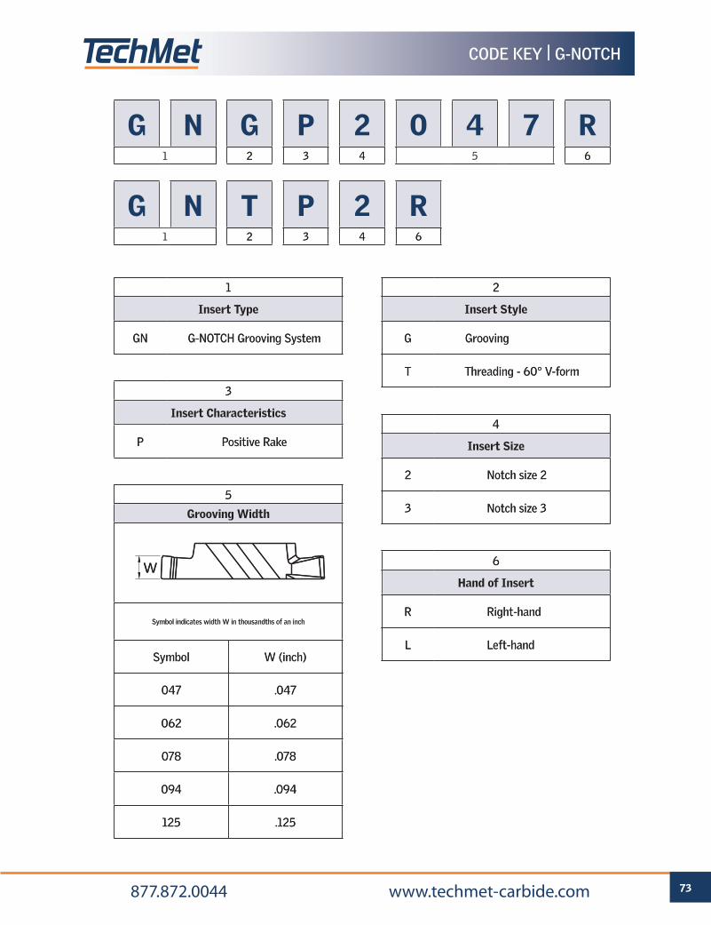
73 877.872.0044 www.techmet-carbide.com
CODE KEY | G-NOTCH
G1
N G2
P3
24
06
47
78
R61 5
G1
N T2
P3
24
R61
1
Insert Type
GN G-NOTCH Grooving System
2
Insert Style
G Grooving
T Threading - 60° V-form
3
Insert Characteristics
P Positive Rake
4
Insert Size
2 Notch size 2
3 Notch size 3
6
Hand of Insert
R Right-hand
L Left-hand
5
Grooving Width
Symbol indicates width W in thousandths of an inch
Symbol W (inch)
047 .047
062 .062
078 .078
094 .094
125 .125
W
G1
N G2
P3
24
06
47
78
R61 5
G1
N T2
P3
24
R61
1
Insert Type
GN G-NOTCH Grooving System
2
Insert Style
G Grooving
T Threading - 60° V-form
3
Insert Characteristics
P Positive Rake
4
Insert Size
2 Notch size 2
3 Notch size 3
6
Hand of Insert
R Right-hand
L Left-hand
5
Grooving Width
Symbol indicates width W in thousandths of an inch
Symbol W (inch)
047 .047
062 .062
078 .078
094 .094
125 .125
W
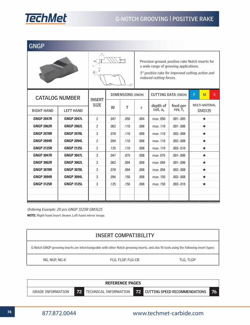
REFERENCE PAGES
GRADE SELECTION GUIDE 6 TECHNICAL INFORMATION 59 CUTTING SPEED RECOMMENDATIONS 66
74 877.872.0044 www.techmet-carbide.com
REFERENCE PAGES
GRADE INFORMATION 72 TECHNICAL INFORMATION 72 CUTTING SPEED RECOMMENDATIONS 76
GNGP
Precision ground, positive rake Notch inserts for a wide range of grooving applications.
5° positive rake for improved cutting action and reduced cutting forces.
CATALOG NUMBER INSERT SIZE
DIMENSIONS (INCH) CUTTING DATA (INCH) P M K
W T r depth of cut, ap
feed per rev, fn
MULTI-MATERIAL
GM3125RIGHT HAND LEFT HAND
GNGP 2047R GNGP 2047L 2 .047 .050 .004 max .050 .001-.005 H
GNGP 2062R GNGP 2062L 2 .062 .110 .008 max .110 .001-.006 H
GNGP 2078R GNGP 2078L 2 .078 .110 .008 max .110 .002-.008 H
GNGP 2094R GNGP 2094L 2 .094 .110 .008 max .110 .002-.008 H
GNGP 2125R GNGP 2125L 2 .125 .110 .008 max .110 .003-.010 H
GNGP 3047R GNGP 3047L 3 .047 .075 .008 max .075 .001-.006 H
GNGP 3062R GNGP 3062L 3 .062 .094 .008 max .094 .001-.006 H
GNGP 3078R GNGP 3078L 3 .078 .094 .008 max .094 .002-.008 H
GNGP 3094R GNGP 3094L 3 .094 .150 .008 max .150 .002-.008 H
GNGP 3125R GNGP 3125L 3 .125 .150 .008 max .150 .003-.010 H
Ordering Example: 20 pcs GNGP 3125R GM3125
NOTE: Right-hand insert shown; Left-hand mirror image.
INSERT COMPATIBILITY
G-Notch GNGP grooving inserts are interchangeable with other Notch grooving inserts, and also fit tools using the following insert types:
NG, NGP, NG-K FLG, FLGP, FLG-CB TLG, TLGP
3°
r
T
W
5°
55°
G-NOTCH GROOVING | POSITIVE RAKE
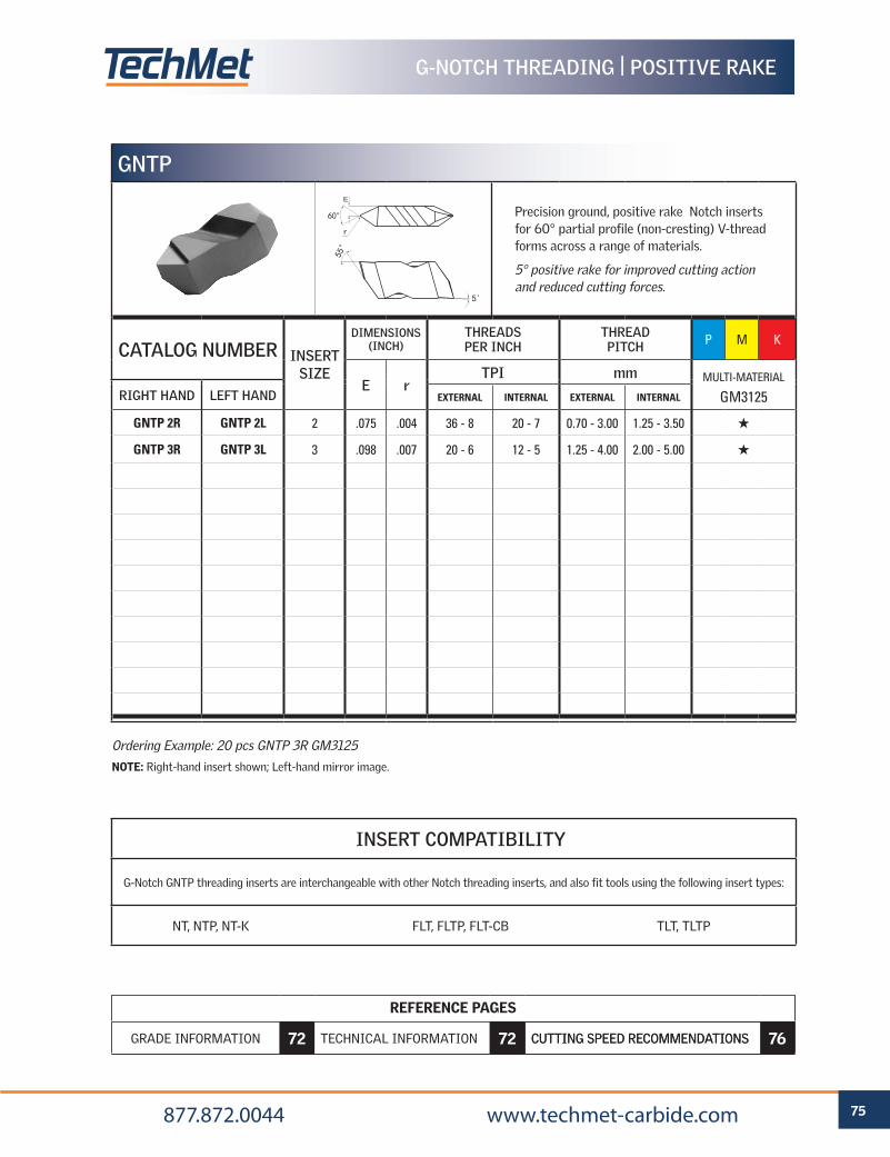
REFERENCE PAGES
GRADE SELECTION GUIDE 6 TECHNICAL INFORMATION 59 CUTTING SPEED RECOMMENDATIONS 66
75 877.872.0044 www.techmet-carbide.com
REFERENCE PAGES
GRADE INFORMATION 72 TECHNICAL INFORMATION 72 CUTTING SPEED RECOMMENDATIONS 76
G-NOTCH THREADING | POSITIVE RAKE
GNTP
CATALOG NUMBER INSERT SIZE
DIMENSIONS (INCH)
THREADS PER INCH
THREAD PITCH P M K
E rTPI mm MULTI-MATERIAL
GM3125RIGHT HAND LEFT HAND EXTERNAL INTERNAL EXTERNAL INTERNAL
GNTP 2R GNTP 2L 2 .075 .004 36 - 8 20 - 7 0.70 - 3.00 1.25 - 3.50 H
GNTP 3R GNTP 3L 3 .098 .007 20 - 6 12 - 5 1.25 - 4.00 2.00 - 5.00 H
Ordering Example: 20 pcs GNTP 3R GM3125
NOTE: Right-hand insert shown; Left-hand mirror image.
r
E
60°
5°
55°
Precision ground, positive rake Notch inserts for 60° partial profile (non-cresting) V-thread forms across a range of materials.
5° positive rake for improved cutting action and reduced cutting forces.
INSERT COMPATIBILITY
G-Notch GNTP threading inserts are interchangeable with other Notch threading inserts, and also fit tools using the following insert types:
NT, NTP, NT-K FLT, FLTP, FLT-CB TLT, TLTP
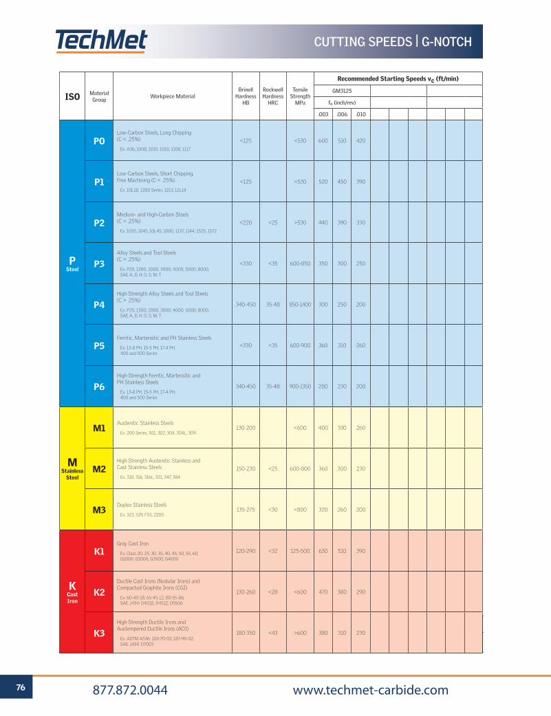
REFERENCE PAGES
GRADE SELECTION GUIDE 6 TECHNICAL INFORMATION 59 CUTTING SPEED RECOMMENDATIONS 66
76 877.872.0044 www.techmet-carbide.com
REFERENCE PAGES
GRADE SELECTION GUIDE 34 TECHNICAL INFORMATION 59 CUTTING SPEED RECOMMENDATIONS 66
ISO Material Group
Workpiece MaterialBrinell
Hardness HB
Rockwell Hardness
HRC
Tensile Strength
MPa
Recommended Starting Speeds vc (ft/min)
GM3125
fn (inch/rev)
.003 .006 .010
P Steel
POLow-Carbon Steels, Long Chipping (C < .25%)
Ex. A36, 1008, 1010, 1018, 1108, 1117
<125 <530 600 510 420
P1Low-Carbon Steels, Short Chipping, Free Machining (C < .25%)
Ex. 10L18, 1200 Series, 1213, 12L14
<125 <530 520 450 390
P2Medium- and High-Carbon Steels (C > .25%)
Ex. 1035, 1045, 10L45, 1080, 1137, 1144, 1525, 1572
<220 <25 >530 440 390 330
P3Alloy Steels and Tool Steels (C > .25%)
Ex. P20, 1300, 2000, 3000, 4000, 5000, 8000, SAE A, D, H, O, S, M, T
<330 <35 600-850 350 300 250
P4High-Strength Alloy Steels and Tool Steels(C > .25%)
Ex. P20, 1300, 2000, 3000, 4000, 5000, 8000, SAE A, D, H, O, S, M, T
340-450 35-48 850-1400 300 250 200
P5Ferritic, Martensitic and PH Stainless Steels
Ex. 13-8 PH, 15-5 PH, 17-4 PH, 400 and 500 Series
<330 <35 600-900 360 310 260
P6High-Strength Ferritic, Martensitic andPH Stainless Steels
Ex. 13-8 PH, 15-5 PH, 17-4 PH, 400 and 500 Series
340-450 35-48 900-1350 280 230 200
M Stainless
Steel
M1Austenitic Stainless Steels
Ex. 200 Series, 301, 302, 304, 304L, 309130-200 <600 400 330 260
M2High-Strength Austenitic Stainless and Cast Stainless Steels
Ex. 310, 316, 316L, 321, 347, 384
150-230 <25 600-800 360 300 230
M3Duplex Stainless Steels
Ex. 323, 329, F55, 2205135-275 <30 <800 320 260 200
K Cast Iron
K1Gray Cast Iron
Ex. Class 20, 25, 30, 35, 40, 45, 50, 55, 60, G1800, G3000, G3500, G4000
120-290 <32 125-500 630 510 390
K2Ductile Cast Irons (Nodular Irons) and Compacted Graphite Irons (CGI)
Ex. 60-40-18, 65-45-12, 80-55-06, SAE J434: D4018, D4512, D5506
130-260 <28 <600 470 380 290
K3High-Strength Ductile Irons and Austempered Ductile Irons (ADI)
Ex. ASTM A536: 100-70-03, 120-90-02, SAE J434: D7003
180-350 <43 >600 380 310 230
r
d
s
r
ds
r
d
s
CUTTING SPEEDS | G-NOTCH
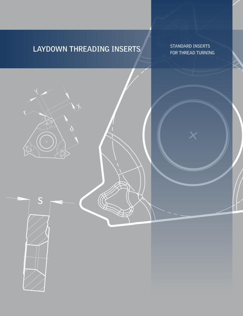
r
d
s
LAYDOWN THREADING INSERTS STANDARD INSERTS
FOR THREAD TURNING
r
ds
r
d
s
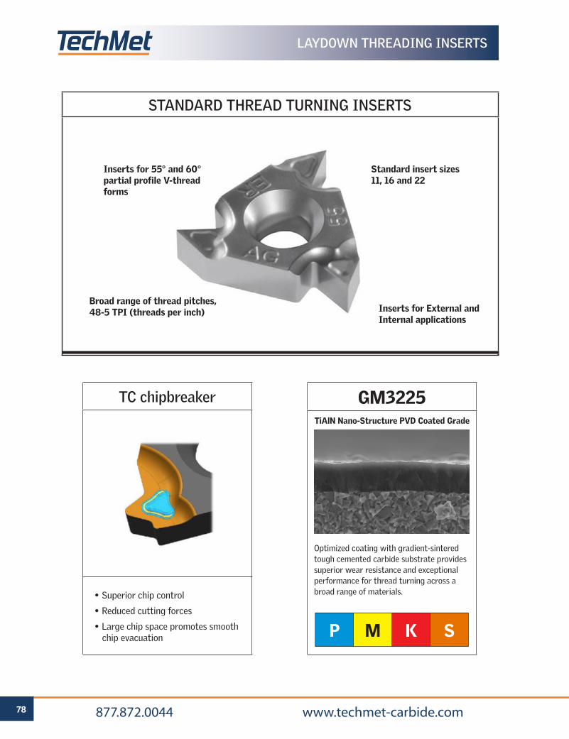
78 877.872.0044 www.techmet-carbide.com
STANDARD THREAD TURNING INSERTS
TC chipbreaker
• Superior chip control
• Reduced cutting forces
• Large chip space promotes smooth chip evacuation
LAYDOWN THREADING INSERTS
GM3225
P M K S
Optimized coating with gradient-sintered tough cemented carbide substrate provides superior wear resistance and exceptional performance for thread turning across a broad range of materials.
TiAlN Nano-Structure PVD Coated Grade
Inserts for 55° and 60° partial profile V-thread forms
Standard insert sizes 11, 16 and 22
Broad range of thread pitches, 48-5 TPI (threads per inch) Inserts for External and
Internal applications
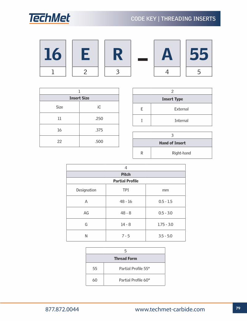
79 877.872.0044 www.techmet-carbide.com
CODE KEY | THREADING INSERTS
161
E2
R3
A4
555
2
Insert Type
E External
I Internal
1
Insert Size
Size iC
11 .250
16 .375
22 .500
3
Hand of Insert
R Right-hand
4
Pitch
Partial Profile
Designation TPI mm
A 48 - 16 0.5 - 1.5
AG 48 - 8 0.5 - 3.0
G 14 - 8 1.75 - 3.0
N 7 - 5 3.5 - 5.0
5
Thread Form
55 Partial Profile 55°
60 Partial Profile 60°
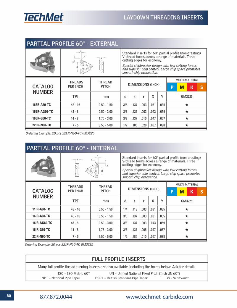
80 877.872.0044 www.techmet-carbide.com
LAYDOWN THREADING INSERTS
PARTIAL PROFILE 60° - EXTERNALStandard inserts for 60° partial profile (non-cresting) V-thread forms across a range of materials. Three cutting edges for economy.
Special chipbreaker design with low cutting forces and superior chip control. Large chip space promotes smooth chip evacuation.
CATALOG NUMBER
THREADS PER INCH
THREAD PITCH DIMENSIONS (INCH)
TPI mm d s r X Y GM3225
16ER-A60-TC 48 - 16 0.50 - 1.50 3/8 .137 .003 .031 .035 H
16ER-AG60-TC 48 - 8 0.50 - 3.00 3/8 .137 .003 .043 .059 H
16ER-G60-TC 14 - 8 1.75 - 3.00 3/8 .137 .010 .047 .067 H
22ER-N60-TC 7 - 5 3.50 - 5.00 1/2 .185 .020 .067 .098 H
P M K S
PARTIAL PROFILE 60° - INTERNALStandard inserts for 60° partial profile (non-cresting) V-thread forms across a range of materials. Three cutting edges for economy.
Special chipbreaker design with low cutting forces and superior chip control. Large chip space promotes smooth chip evacuation.
CATALOG NUMBER
THREADS PER INCH
THREAD PITCH DIMENSIONS (INCH)
TPI mm d s r X Y GM3225
11IR-A60-TC 48 - 16 0.50 - 1.50 1/4 .118 .003 .031 .035 H
16IR-A60-TC 48 - 16 0.50 - 1.50 3/8 .137 .003 .031 .035 H
16IR-AG60-TC 48 - 8 0.50 - 3.00 3/8 .137 .003 .043 .059 H
16IR-G60-TC 14 - 8 1.75 - 3.00 3/8 .137 .005 .047 .067 H
22IR-N60-TC 7 - 5 3.50 - 5.00 1/2 .185 .010 .067 .098 H
P M K S
Ordering Example: 20 pcs 22ER-N60-TC GM3225
Ordering Example: 20 pcs 22IR-N60-TC GM3225
MULTI-MATERIAL
MULTI-MATERIAL
FULL PROFILE INSERTSMany full profile thread turning inserts are also available, including the forms below. Ask for details.
ISO – ISO Metric 60° UN – Unified National Fixed Pitch (Inch UN 60°) NPT – National Pipe Taper BSPT – British Standard Pipe Taper W - Whitworth
sr
d
d
rs
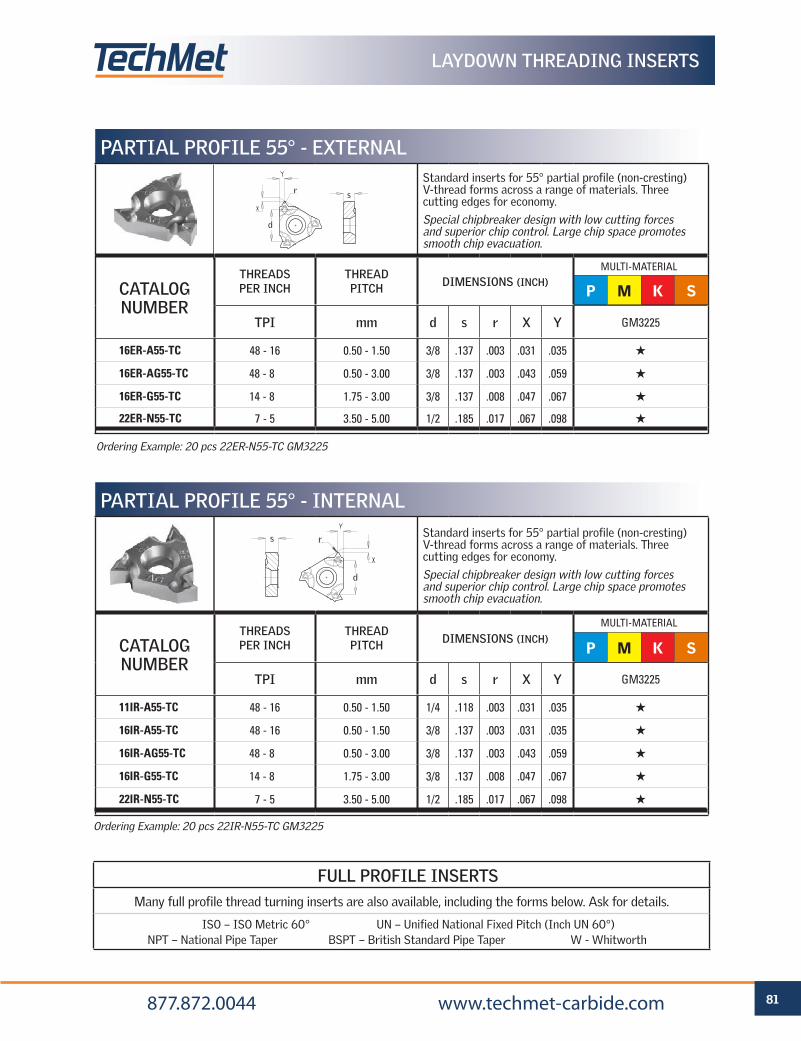
81 877.872.0044 www.techmet-carbide.com
LAYDOWN THREADING INSERTS
PARTIAL PROFILE 55° - EXTERNALStandard inserts for 55° partial profile (non-cresting) V-thread forms across a range of materials. Three cutting edges for economy.
Special chipbreaker design with low cutting forces and superior chip control. Large chip space promotes smooth chip evacuation.
CATALOG NUMBER
THREADS PER INCH
THREAD PITCH DIMENSIONS (INCH)
TPI mm d s r X Y GM3225
16ER-A55-TC 48 - 16 0.50 - 1.50 3/8 .137 .003 .031 .035 H
16ER-AG55-TC 48 - 8 0.50 - 3.00 3/8 .137 .003 .043 .059 H
16ER-G55-TC 14 - 8 1.75 - 3.00 3/8 .137 .008 .047 .067 H
22ER-N55-TC 7 - 5 3.50 - 5.00 1/2 .185 .017 .067 .098 H
P M K S
PARTIAL PROFILE 55° - INTERNALStandard inserts for 55° partial profile (non-cresting) V-thread forms across a range of materials. Three cutting edges for economy.
Special chipbreaker design with low cutting forces and superior chip control. Large chip space promotes smooth chip evacuation.
CATALOG NUMBER
THREADS PER INCH
THREAD PITCH DIMENSIONS (INCH)
TPI mm d s r X Y GM3225
11IR-A55-TC 48 - 16 0.50 - 1.50 1/4 .118 .003 .031 .035 H
16IR-A55-TC 48 - 16 0.50 - 1.50 3/8 .137 .003 .031 .035 H
16IR-AG55-TC 48 - 8 0.50 - 3.00 3/8 .137 .003 .043 .059 H
16IR-G55-TC 14 - 8 1.75 - 3.00 3/8 .137 .008 .047 .067 H
22IR-N55-TC 7 - 5 3.50 - 5.00 1/2 .185 .017 .067 .098 H
P M K S
Ordering Example: 20 pcs 22ER-N55-TC GM3225
Ordering Example: 20 pcs 22IR-N55-TC GM3225
MULTI-MATERIAL
MULTI-MATERIAL
FULL PROFILE INSERTSMany full profile thread turning inserts are also available, including the forms below. Ask for details.
ISO – ISO Metric 60° UN – Unified National Fixed Pitch (Inch UN 60°) NPT – National Pipe Taper BSPT – British Standard Pipe Taper W - Whitworth
sr
d
d
rs
d
rs
sr
d
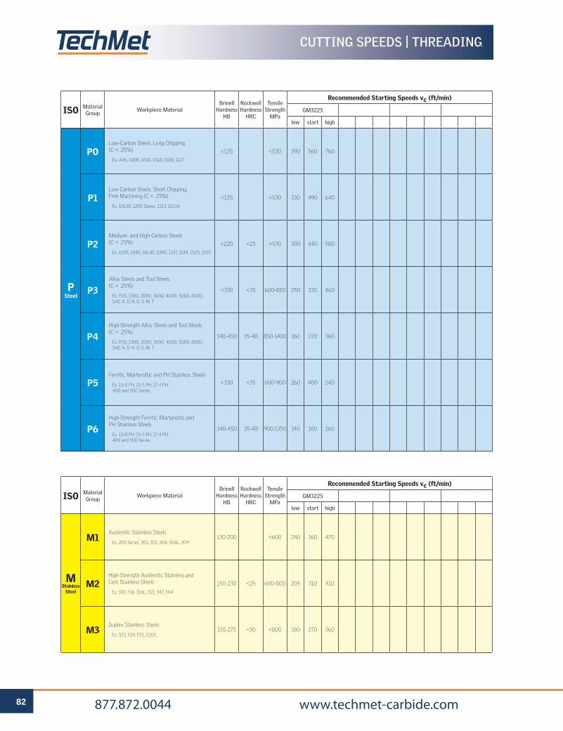
82 877.872.0044 www.techmet-carbide.com
CUTTING SPEEDS | THREADING
ISO Material Group
Workpiece MaterialBrinell
Hardness HB
Rockwell Hardness
HRC
Tensile Strength
MPa
Recommended Starting Speeds vc (ft/min)
GM3225
low start high
P Steel
POLow-Carbon Steels, Long Chipping (C < .25%)
Ex. A36, 1008, 1010, 1018, 1108, 1117
<125 <530 390 560 760
P1Low-Carbon Steels, Short Chipping, Free Machining (C < .25%)
Ex. 10L18, 1200 Series, 1213, 12L14
<125 <530 330 490 640
P2Medium- and High-Carbon Steels (C > .25%)
Ex. 1035, 1045, 10L45, 1080, 1137, 1144, 1525, 1572
<220 <25 >530 300 440 580
P3Alloy Steels and Tool Steels (C > .25%)
Ex. P20, 1300, 2000, 3000, 4000, 5000, 8000, SAE A, D, H, O, S, M, T
<330 <35 600-850 250 330 460
P4High-Strength Alloy Steels and Tool Steels(C > .25%)
Ex. P20, 1300, 2000, 3000, 4000, 5000, 8000, SAE A, D, H, O, S, M, T
340-450 35-48 850-1400 160 270 360
P5Ferritic, Martensitic and PH Stainless Steels
Ex. 13-8 PH, 15-5 PH, 17-4 PH, 400 and 500 Series
<330 <35 600-900 260 400 540
P6High-Strength Ferritic, Martensitic andPH Stainless Steels
Ex. 13-8 PH, 15-5 PH, 17-4 PH, 400 and 500 Series
340-450 35-48 900-1350 140 180 260
ISO Material Group
Workpiece MaterialBrinell
Hardness HB
Rockwell Hardness
HRC
Tensile Strength
MPa
Recommended Starting Speeds vc (ft/min)
GM3225
low start high
M Stainless
Steel
M1Austenitic Stainless Steels
Ex. 200 Series, 301, 302, 304, 304L, 309130-200 <600 240 360 470
M2High-Strength Austenitic Stainless and Cast Stainless Steels
Ex. 310, 316, 316L, 321, 347, 384
150-230 <25 600-800 205 310 410
M3Duplex Stainless Steels
Ex. 323, 329, F55, 2205135-275 <30 <800 180 270 360
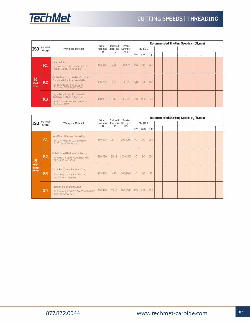
83 877.872.0044 www.techmet-carbide.com
CUTTING SPEEDS | THREADING
ISO Material Group
Workpiece MaterialBrinell
Hardness HB
Rockwell Hardness
HRC
Tensile Strength
MPa
Recommended Starting Speeds vc (ft/min)
GM3225
low start high
K Cast Iron
K1Gray Cast Iron
Ex. Class 20, 25, 30, 35, 40, 45, 50, 55, 60, G1800, G3000, G3500, G4000
120-290 <32 125-500 260 350 490
K2Ductile Cast Irons (Nodular Irons) and Compacted Graphite Irons (CGI)
Ex. 60-40-18, 65-45-12, 80-55-06, SAE J434: D4018, D4512, D5506
130-260 <28 <600 220 300 400
K3High-Strength Ductile Irons and Austempered Ductile Irons (ADI)
Ex. ASTM A536: 100-70-03, 120-90-02, SAE J434: D7003
180-350 <43 >600 200 260 320
ISO Material Group
Workpiece MaterialBrinell
Hardness HB
Rockwell Hardness
HRC
Tensile Strength
MPa
Recommended Starting Speeds vc (ft/min)
GM3225
low start high
S High Temp Alloys
S1Iron-Based Heat-Resistant Alloys
Ex. A286, A608, INCOLOY 800 Series, N-155, Haynes 556, Discaloy
160-260 25-48 500-1200 90 130 180
S2Cobalt-Based Heat-Resistant Alloys
Ex. Haynes 25 (L605), Haynes 188, Stellite, MAR-M302, MAR-M509
250-450 25-48 1000-1450 60 80 100
S3Nickel-Based Heat-Resistant Alloys
Ex. Astroloy, Hastelloy X, INCONEL 600
and 700 Series, Waspalloy
160-450 <48 600-1700 45 60 80
S4Titanium and Titanium Alloys
Ex. Commercially Pure Ti, Ti-5Al-2.5Sn, Ti-6Al-4V, Ti-3Al-8V-6Cr-4Zr-4Mo
300-400 33-48 900-1600 165 200 230
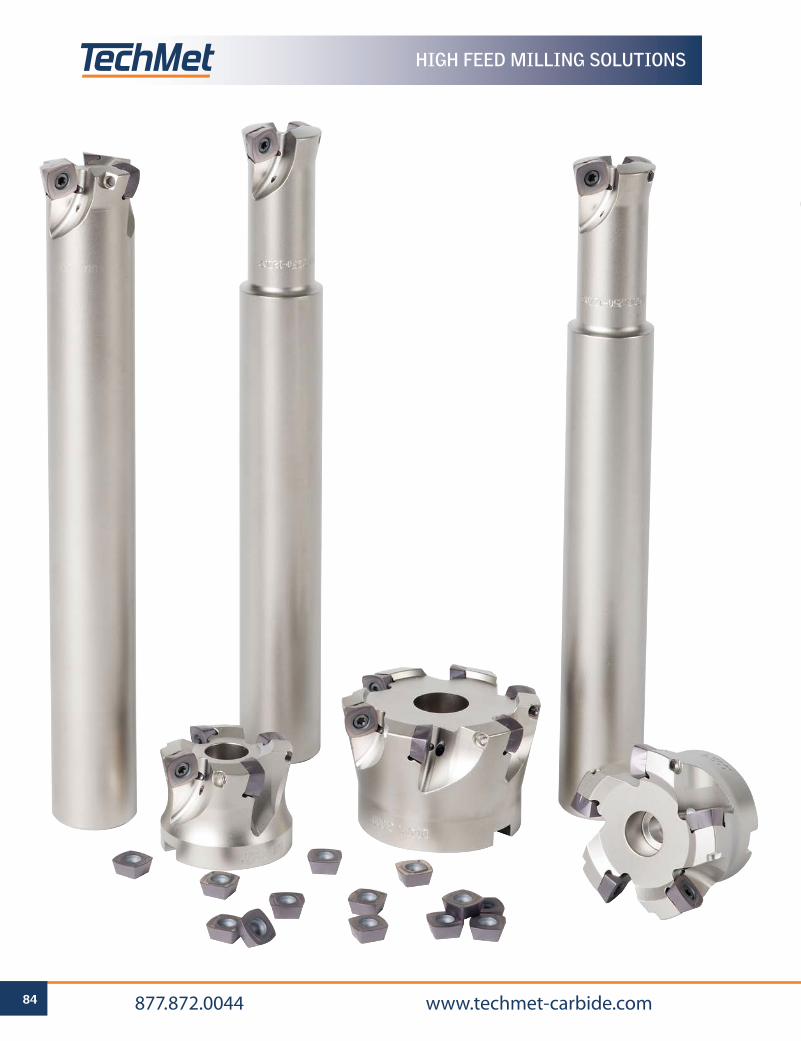
84 877.872.0044 www.techmet-carbide.com
HIGH FEED MILLING SOLUTIONS

High Feed Milling Solutions 86
Standard Milling Inserts 95
MILLING
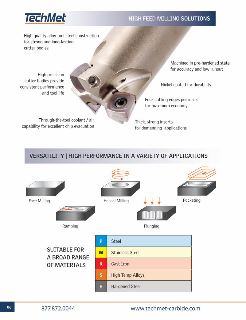
86 877.872.0044 www.techmet-carbide.com
High quality alloy tool steel construction for strong and long-lasting cutter bodies
High precision cutter bodies provide
consistent performance and tool life
Through-the-tool coolant / air capability for excellent chip evacuation
VERSATILITY | HIGH PERFORMANCE IN A VARIETY OF APPLICATIONS
SUITABLE FOR A BROAD RANGE OF MATERIALS
P Steel
M Stainless Steel
K Cast Iron
S High Temp Alloys
H Hardened Steel
Face Milling Helical Milling Pocketing
PlungingRamping
HIGH FEED MILLING SOLUTIONS
Thick, strong inserts for demanding applications
Four cutting edges per insert for maximum economy
Nickel coated for durability
Machined in pre-hardened state for accuracy and low runout
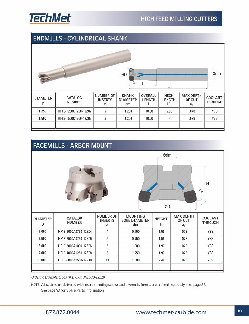
87 877.872.0044 www.techmet-carbide.com
HIGH FEED MILLING CUTTERS
LL1ap
ØD Ødm
ENDMILLS - CYLINDRICAL SHANK
DIAMETERD
CATALOG NUMBER
NUMBER OF INSERTS
z
SHANK DIAMETER
dm
OVERALL LENGTH
L
NECK LENGTH
L1
MAX DEPTH OF CUT
ap
COOLANT THROUGH
1.250 HF13-1250C1250-12Z02 2 1.250 10.00 2.50 .078 YES
1.500 HF13-1500C1250-12Z03 3 1.250 10.00 - .078 YES
FACEMILLS - ARBOR MOUNT
DIAMETERD
CATALOG NUMBER
NUMBER OF INSERTS
z
MOUNTING BORE DIAMETER
dm
HEIGHTH
MAX DEPTH OF CUT
ap
COOLANT THROUGH
2.000 HF13-2000A0750-12Z04 4 0.750 1.58 .078 YES
2.500 HF13-2500A0750-12Z05 5 0.750 1.58 .078 YES
3.000 HF13-3000A1000-12Z06 6 1.000 1.97 .078 YES
4.000 HF13-4000A1250-12Z08 8 1.250 1.97 .078 YES
5.000 HF13-5000A1500-12Z10 10 1.500 2.48 .078 YES
Ordering Example: 2 pcs HF13-5000A1500-12Z10
NOTE: All cutters are delivered with insert mounting screws and a wrench. Inserts are ordered separately - see page 88.
See page 93 for Spare Parts information.
ØD
Ødm
ap
H
Machined in pre-hardened state for accuracy and low runout
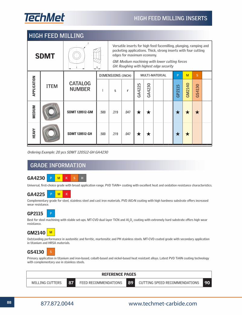
88 877.872.0044 www.techmet-carbide.com
Ordering Example: 20 pcs SDMT 120512-GH GA4230
HIGH FEED MILLING
Versatile inserts for high feed facemilling, plunging, ramping and pocketing applications. Thick, strong inserts with four cutting edges for maximum economy.
GM: Medium machining with lower cutting forces GH: Roughing with highest edge security
APP
LICA
TIO
N
ITEM CATALOG NUMBER
DIMENSIONS (INCH) MULTI-MATERIAL P M S
l s r
GA
4225
GA
4230
GP2
115
GM
2140
GS4
130
MED
IUM
SDMT 120512-GM .500 .219 .047 H H H H H
HEA
VY
SDMT 120512-GH .500 .219 .047 H H H H
SDMTl
r
S
GA4230Universal, first-choice grade with broad application range. PVD TiAlN+ coating with excellent heat and oxidation resistance characteristics.
GA4225Complementary grade for steel, stainless steel and cast iron materials. PVD AlCrN coating with high hardness substrate offers increased wear resistance.
GP2115Best for steel machining with stable set-ups. MT-CVD dual layer TiCN and Al2O3 coating with extremely hard substrate offers high wear resistance.
GM2140Outstanding performance in austenitic and ferritic, martensitic and PH stainless steels. MT-CVD coated grade with secondary application in titanium and HRSA materials.
GS4130Primary application in titanium and iron-based, cobalt-based and nickel-based heat resistant alloys. Latest PVD TiAlN coating technology with complementary use in stainless steels.
P M K S H
P M K
GRADE INFORMATION
HIGH FEED MILLING INSERTS
P
M
S
REFERENCE PAGES
MILLING CUTTERS 87 FEED RECOMMENDATIONS 89 CUTTING SPEED RECOMMENDATIONS 90
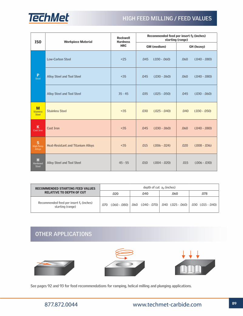
89 877.872.0044 www.techmet-carbide.com
ISO Workpiece MaterialRockwell Hardness
HRC
Recommended feed per insert fz (inches) starting (range)
GM (medium) GH (heavy)
P Steel
Low-Carbon Steel <25 .045 (.030 - .060) .060 (.040 - .080)
Alloy Steel and Tool Steel <35 .045 (.030 - .060) .060 (.040 - .080)
Alloy Steel and Tool Steel 35 - 45 .035 (.025 - .050) .045 (.030 - .060)
M Stainless
SteelStainless Steel <35 .030 (.025 - .040) .040 (.030 - .050)
K Cast Iron
Cast Iron <35 .045 (.030 - .060) .060 (.040 - .080)
S High-Temp
AlloysHeat-Resistant and Titanium Alloys <35 .015 (.006 - .024) .020 (.008 - .036)
H Hardened
SteelAlloy Steel and Tool Steel 45 - 55 .010 (.004 - .020) .015 (.006 - .030)
RECOMMENDED STARTING FEED VALUES RELATIVE TO DEPTH OF CUT
depth of cut ap (inches)
.020 .040 .060 .078
Recommended feed per insert fz (inches) starting (range) .070 (.060 - .080) .060 (.040 - .070) .040 (.025 - .060) .030 (.015 - .040)
See pages 92 and 93 for feed recommendations for ramping, helical milling and plunging applications.
OTHER APPLICATIONS
HIGH FEED MILLING / FEED VALUES
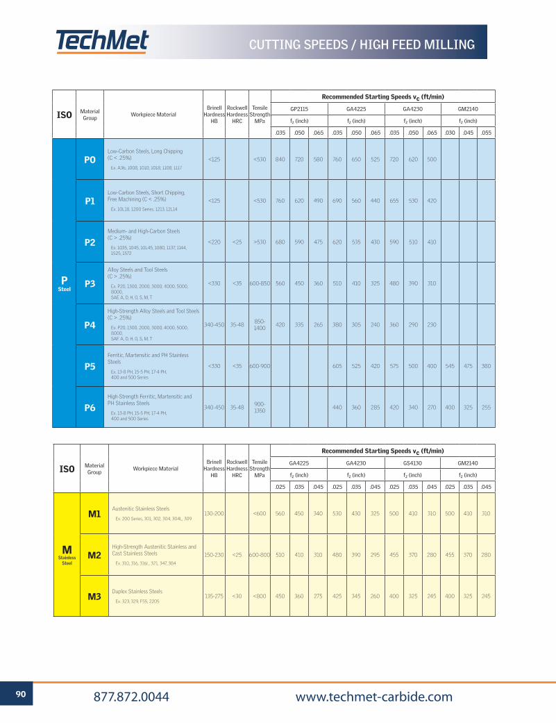
90 877.872.0044 www.techmet-carbide.com
ISO Material Group
Workpiece MaterialBrinell
Hardness HB
Rockwell Hardness
HRC
Tensile Strength
MPa
Recommended Starting Speeds vc (ft/min)
GP2115 GA4225 GA4230 GM2140
fz (inch) fz (inch) fz (inch) fz (inch)
.035 .050 .065 .035 .050 .065 .035 .050 .065 .030 .045 .055
P Steel
POLow-Carbon Steels, Long Chipping (C < .25%)
Ex. A36, 1008, 1010, 1018, 1108, 1117
<125 <530 840 720 580 760 650 525 720 620 500
P1Low-Carbon Steels, Short Chipping, Free Machining (C < .25%)
Ex. 10L18, 1200 Series, 1213, 12L14
<125 <530 760 620 490 690 560 440 655 530 420
P2Medium- and High-Carbon Steels (C > .25%)
Ex. 1035, 1045, 10L45, 1080, 1137, 1144, 1525, 1572
<220 <25 >530 680 590 475 620 535 430 590 510 410
P3
Alloy Steels and Tool Steels (C > .25%)
Ex. P20, 1300, 2000, 3000, 4000, 5000, 8000, SAE A, D, H, O, S, M, T
<330 <35 600-850 560 450 360 510 410 325 480 390 310
P4
High-Strength Alloy Steels and Tool Steels(C > .25%)
Ex. P20, 1300, 2000, 3000, 4000, 5000, 8000, SAE A, D, H, O, S, M, T
340-450 35-48850-1400
420 335 265 380 305 240 360 290 230
P5Ferritic, Martensitic and PH Stainless Steels
Ex. 13-8 PH, 15-5 PH, 17-4 PH, 400 and 500 Series
<330 <35 600-900 605 525 420 575 500 400 545 475 380
P6High-Strength Ferritic, Martensitic andPH Stainless Steels
Ex. 13-8 PH, 15-5 PH, 17-4 PH, 400 and 500 Series
340-450 35-48900-1350
440 360 285 420 340 270 400 325 255
CUTTING SPEEDS / HIGH FEED MILLING
ISO Material Group
Workpiece MaterialBrinell
Hardness HB
Rockwell Hardness
HRC
Tensile Strength
MPa
Recommended Starting Speeds vc (ft/min)
GA4225 GA4230 GS4130 GM2140
fz (inch) fz (inch) fz (inch) fz (inch)
.025 .035 .045 .025 .035 .045 .025 .035 .045 .025 .035 .045
M Stainless
Steel
M1Austenitic Stainless Steels
Ex. 200 Series, 301, 302, 304, 304L, 309130-200 <600 560 450 340 530 430 325 500 410 310 500 410 310
M2High-Strength Austenitic Stainless and Cast Stainless Steels
Ex. 310, 316, 316L, 321, 347, 384
150-230 <25 600-800 510 410 310 480 390 295 455 370 280 455 370 280
M3Duplex Stainless Steels
Ex. 323, 329, F55, 2205135-275 <30 <800 450 360 275 425 345 260 400 325 245 400 325 245

91 877.872.0044 www.techmet-carbide.com
ISO Material Group
Workpiece MaterialBrinell
Hardness HB
Rockwell Hardness
HRC
Tensile Strength
MPa
Recommended Starting Speeds vc (ft/min)
GA4225 GA4230
fz (inch) fz (inch)
.035 .050 .065 .035 .050 .065
K Cast Iron
K1Gray Cast Iron
Ex. Class 20, 25, 30, 35, 40, 45, 50, 55, 60, G1800, G3000, G3500, G4000
120-290 <32 125-500 690 560 440 655 530 420
K2Ductile Cast Irons (Nodular Irons) and Compacted Graphite Irons (CGI)
Ex. 60-40-18, 65-45-12, 80-55-06, SAE J434: D4018, D4512, D5506
130-260 <28 <600 620 520 390 590 490 370
K3High-Strength Ductile Irons and Austempered Ductile Irons (ADI)
Ex. ASTM A536: 100-70-03, 120-90-02, SAE J434: D7003
180-350 <43 >600 550 470 360 525 450 345
ISO Material Group
Workpiece MaterialBrinell
Hardness HB
Rockwell Hardness
HRC
Tensile Strength
MPa
Recommended Starting Speeds vc (ft/min)
GA4230 GS4130 GM2140
fz (inch) fz (inch) fz (inch)
.008 .016 .024 .008 .016 .024 .008 .016 .024
S High Temp Alloys
S1Iron-Based Heat-Resistant Alloys
Ex. A286, A608, INCOLOY 800 Series, N-155, Haynes 556, Discaloy
160-260 25-48 500-1200 200 130 100 190 120 90 190 120 90
S2Cobalt-Based Heat-Resistant Alloys
Ex. Haynes 25 (L605), Haynes 188, Stellite, MAR-M302, MAR-M509
250-450 25-48 1000-1450 170 100 80 160 90 70 160 90 70
S3Nickel-Based Heat-Resistant Alloys
Ex. Astroloy, Hastelloy X, INCONEL 600
and 700 Series, Waspalloy
160-450 <48 600-1700 180 110 90 170 100 80 170 100 80
S4Titanium and Titanium Alloys
Ex. Commercially Pure Ti, Ti-5Al-2.5Sn, Ti-6Al-4V, Ti-3Al-8V-6Cr-4Zr-4Mo
300-400 33-48 900-1600 190 120 95 180 110 85 180 110 85
ISO Material Group
Workpiece MaterialBrinell
Hardness HB
Rockwell Hardness
HRC
Tensile Strength
MPa
Recommended Starting Speeds vc (ft/min)
GA4230
fz (inch)
.006 .012 .020
H Hardened
Steels
H1Hardened Alloy Steels and Tool Steels
Ex. H13,D2, D3, 4340,P2044-48 320 260 210
H2Hardened Alloy Steels and Tool Steels
Ex. H13,D2, D3, 4340,P2048-55 260 210 165
H3Hardened Alloy Steels and Tool Steels
Ex. H13,D2, D3, 4340,P2056-60
H4Hardened Alloy Steels and Tool Steels
Ex. H13,D2, D3, 4340,P20>60
CUTTING SPEEDS / HIGH FEED MILLING
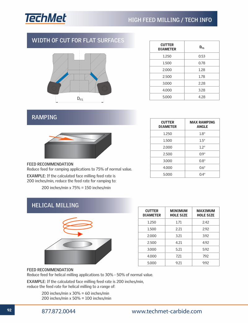
92 877.872.0044 www.techmet-carbide.com
WIDTH OF CUT FOR FLAT SURFACES
RAMPING
HELICAL MILLING
FEED RECOMMENDATION Reduce feed for ramping applications to 75% of normal value.
EXAMPLE: If the calculated face milling feed rate is 200 inches/min, reduce the feed rate for ramping to:
200 inches/min x 75% = 150 inches/min
FEED RECOMMENDATIONReduce feed for helical milling applications to 30% - 50% of normal value.
EXAMPLE: If the calculated face milling feed rate is 200 inches/min, reduce the feed rate for helical milling to a range of:
200 inches/min x 30% = 60 inches/min 200 inches/min x 50% = 100 inches/min
CUTTER DIAMETER DFS
1.250 0.53
1.500 0.78
2.000 1.28
2.500 1.78
3.000 2.28
4.000 3.28
5.000 4.28
CUTTER DIAMETER
MAX RAMPING ANGLE
1.250 1.8°
1.500 1.5°
2.000 1.2°
2.500 0.9°
3.000 0.8°
4.000 0.6°
5.000 0.4°
CUTTER DIAMETER
MINIMUM HOLE SIZE
MAXIMUM HOLE SIZE
1.250 1.71 2.42
1.500 2.21 2.92
2.000 3.21 3.92
2.500 4.21 4.92
3.000 5.21 5.92
4.000 7.21 7.92
5.000 9.21 9.92
DFS
HIGH FEED MILLING / TECH INFO
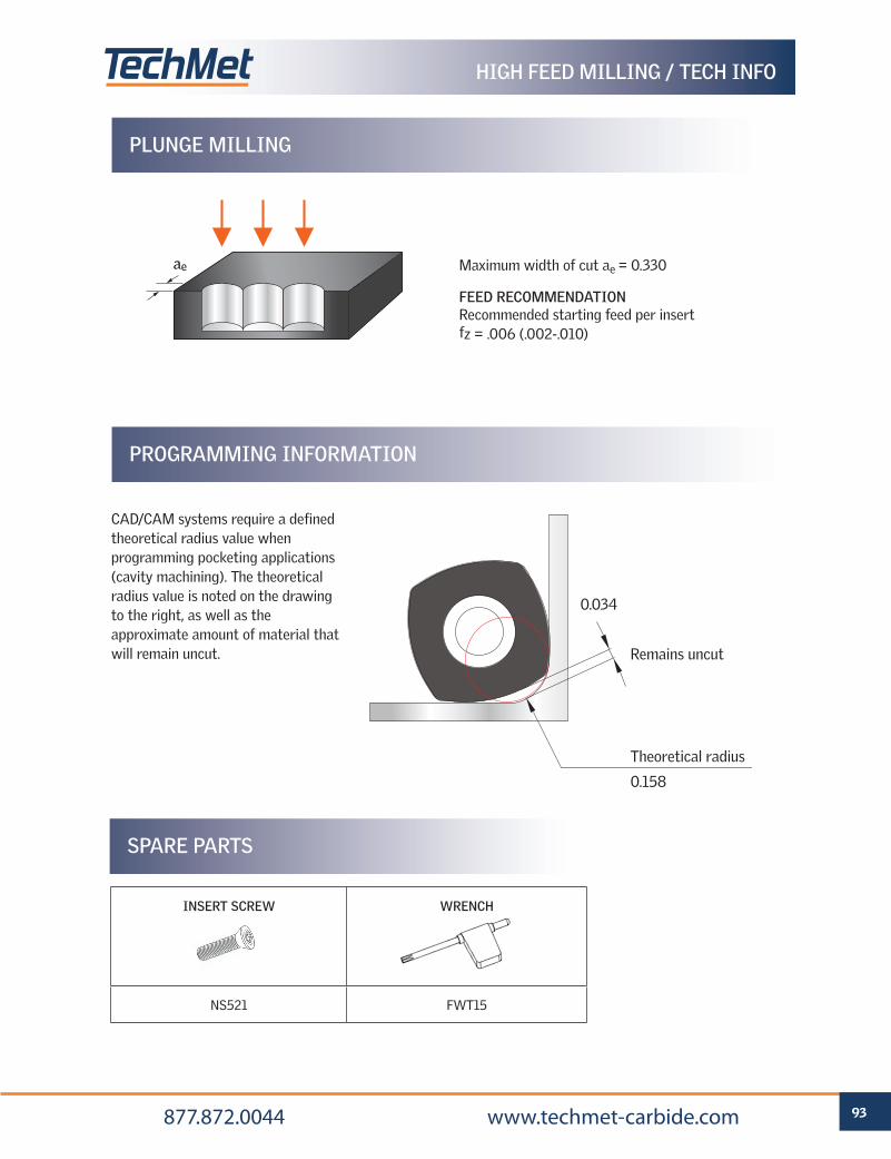
93 877.872.0044 www.techmet-carbide.com
PLUNGE MILLING
PROGRAMMING INFORMATION
CAD/CAM systems require a defined theoretical radius value when programming pocketing applications (cavity machining). The theoretical radius value is noted on the drawing to the right, as well as the approximate amount of material that will remain uncut.
Maximum width of cut ae = 0.330
Theoretical radius
0.158
0.034
Remains uncut
SPARE PARTS
INSERT SCREW WRENCH
NS521 FWT15
ae
FEED RECOMMENDATION Recommended starting feed per insert fz = .006 (.002-.010)
HIGH FEED MILLING / TECH INFO
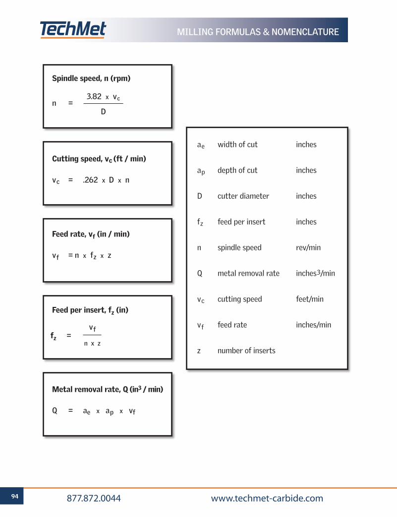
94 877.872.0044 www.techmet-carbide.com
ae width of cut inches
ap depth of cut inches
D cutter diameter inches
fz feed per insert inches
n spindle speed rev/min
Q metal removal rate inches3/min
vc cutting speed feet/min
vf feed rate inches/min
z number of inserts
Cutting speed, vc (ft / min)
vc = .262 x D x n
Feed rate, vf (in / min)
vf = n x fz x z
Metal removal rate, Q (in3 / min)
Q = ae x ap x vf
Spindle speed, n (rpm)
Feed per insert, fz (in)
3.82 x vc
Dn =
vf
n x zfz =
MILLING FORMULAS & NOMENCLATURE

MILLING INSERTSINDUSTRY STANDARD INSERTS
FOR SQUARE SHOULDER, FACEMILLING
AND PROFILE MILLING APPLICATIONS
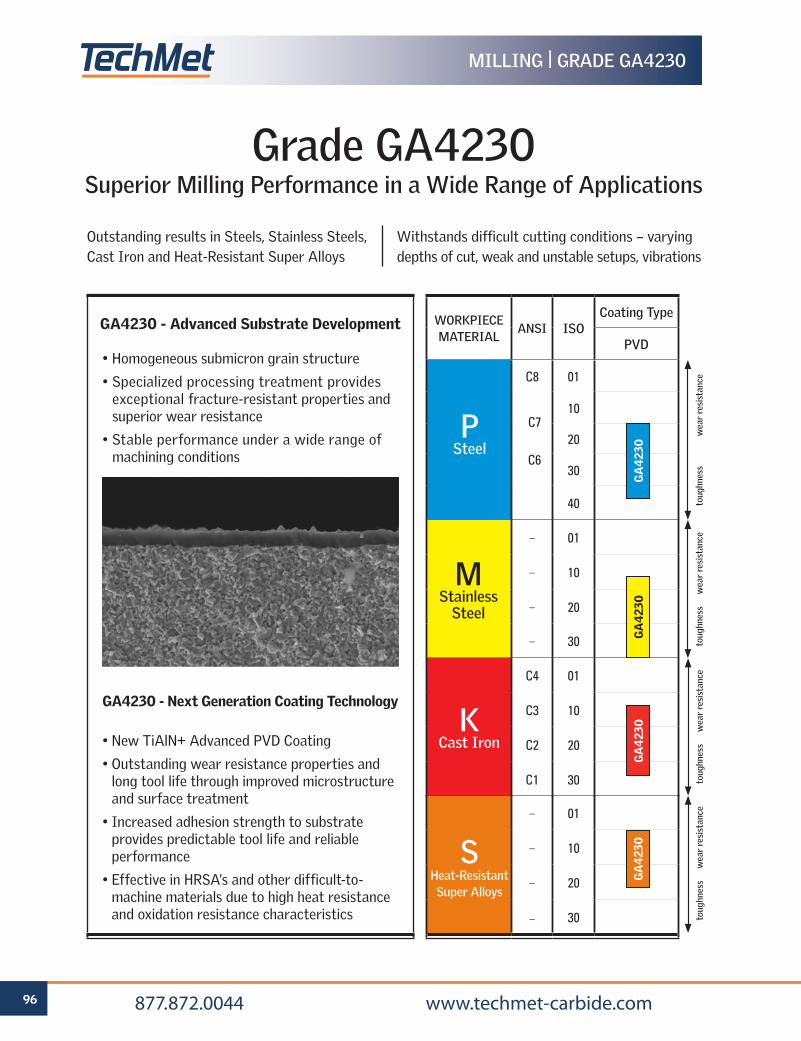
96 877.872.0044 www.techmet-carbide.com
MILLING | GRADE GA4230
Grade GA4230Superior Milling Performance in a Wide Range of Applications
Outstanding results in Steels, Stainless Steels, Cast Iron and Heat-Resistant Super Alloys
Withstands difficult cutting conditions – varying depths of cut, weak and unstable setups, vibrations
• Homogeneous submicron grain structure
• Specialized processing treatment provides exceptional fracture-resistant properties and superior wear resistance
• Stable performance under a wide range of machining conditions
• New TiAlN+ Advanced PVD Coating
• Outstanding wear resistance properties and long tool life through improved microstructure and surface treatment
• Increased adhesion strength to substrate provides predictable tool life and reliable performance
• Effective in HRSA’s and other difficult-to-machine materials due to high heat resistance and oxidation resistance characteristics
GA4230 - Next Generation Coating Technology
GA4230 - Advanced Substrate Development
C4 01
C3 10
C2 20
C1 30
– 01
– 10
– 20
– 30
WORKPIECEMATERIAL
ANSI ISOCoating Type
PVD
C8 01
10
20
30
40
GA
423
0
PSteel
toug
hnes
s w
ear
resi
stan
ce
– 01
– 10
– 20
– 30 GA
423
0
MStainless
Steel
toug
hnes
s w
ear
resi
stan
ce
KCast Iron
GA
423
0
toug
hnes
s w
ear
resi
stan
ce
C7
C6
SHeat-ResistantSuper Alloys
toug
hnes
s w
ear
resi
stan
ce
GA
423
0
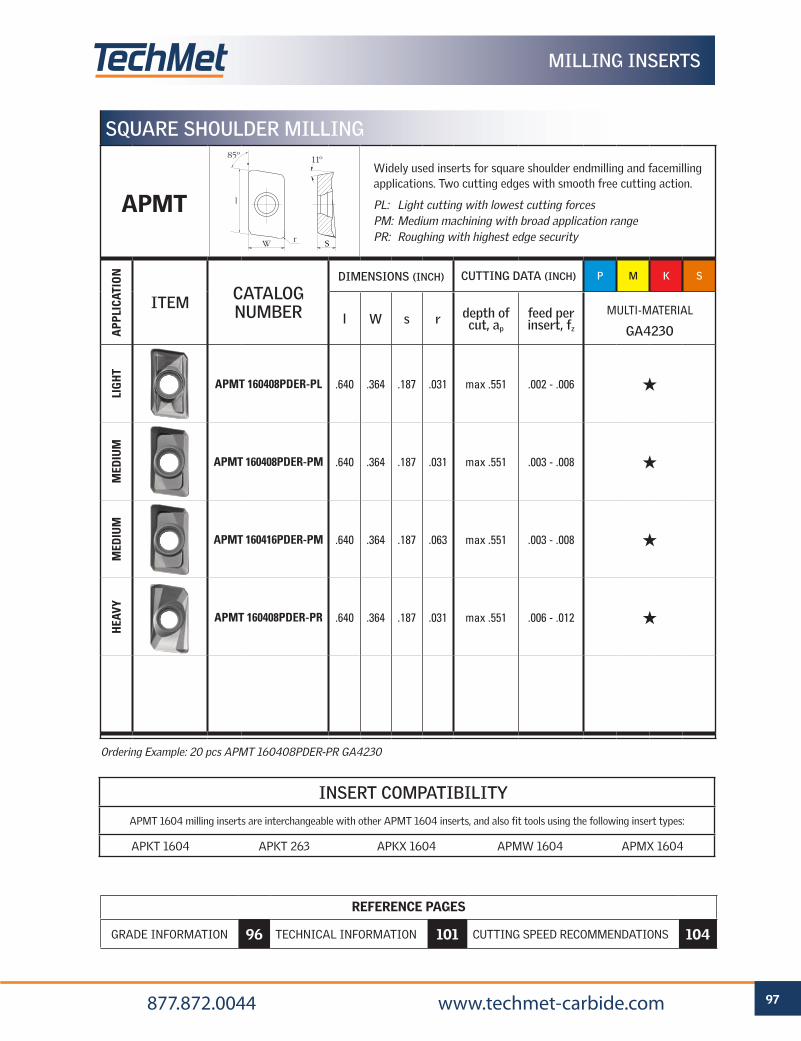
REFERENCE PAGES
GRADE INFORMATION 96 TECHNICAL INFORMATION 101 CUTTING SPEED RECOMMENDATIONS 104
97 877.872.0044 www.techmet-carbide.com
MILLING INSERTS
INSERT COMPATIBILITY
APMT 1604 milling inserts are interchangeable with other APMT 1604 inserts, and also fit tools using the following insert types:
APKT 1604 APKT 263 APKX 1604 APMW 1604 APMX 1604
Ordering Example: 20 pcs APMT 160408PDER-PR GA4230
SQUARE SHOULDER MILLINGA
PPLI
CATI
ON
ITEM CATALOG NUMBER
DIMENSIONS (INCH) CUTTING DATA (INCH) P M K S
l W s r depth of cut, ap
feed per insert, fz
MULTI-MATERIAL
GA4230
LIG
HT
APMT 160408PDER-PL .640 .364 .187 .031 max .551 .002 - .006 H
MED
IUM
APMT 160408PDER-PM .640 .364 .187 .031 max .551 .003 - .008 H
MED
IUM
APMT 160416PDER-PM .640 .364 .187 .063 max .551 .003 - .008 H
HEA
VY
APMT 160408PDER-PR .640 .364 .187 .031 max .551 .006 - .012 H
Widely used inserts for square shoulder endmilling and facemilling applications. Two cutting edges with smooth free cutting action.
PL: Light cutting with lowest cutting forcesPM: Medium machining with broad application rangePR: Roughing with highest edge security
APMT
85º 11º
W
l
r S
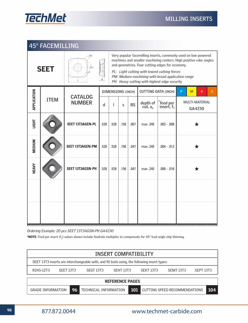
REFERENCE PAGES
GRADE INFORMATION 96 TECHNICAL INFORMATION 101 CUTTING SPEED RECOMMENDATIONS 104
98 877.872.0044 www.techmet-carbide.com
Ordering Example: 20 pcs SEET 13T3AGSN-PH GA4230
*NOTE: Feed per insert (fZ) values shown include feedrate multiplier to compensate for 45° lead angle chip thinning.
45° FACEMILLING
APP
LICA
TIO
N
ITEM CATALOG NUMBER
DIMENSIONS (INCH) CUTTING DATA (INCH) P M K S
d l s BS depth of cut, ap
feed per insert, fZ
MULTI-MATERIAL
GA4230
LIG
HT
SEET 13T3AGEN-PL .528 .528 .156 .067 max .240 .003 - .008 H
MED
IUM
SEET 13T3AGEN-PM .528 .528 .156 .047 max .240 .004 - .012 H
HEA
VY
SEET 13T3AGSN-PH .528 .528 .156 .047 max .240 .006 - .016 H
MILLING INSERTS
Very popular facemilling inserts, commonly used on low powered machines and smaller machining centers. High positive rake angles and geometries. Four cutting edges for economy.
PL: Light cutting with lowest cutting forcesPM: Medium machining with broad application rangePH: Heavy cutting with highest edge security
SEET
INSERT COMPATIBILITYSEET 13T3 inserts are interchangeable with, and fit tools using, the following insert types:
R245-12T3 SEET 13T3 SEGT 13T3 SEHT 13T3 SEKT 13T3 SEMT 13T3 SEPT 13T3
*
d
BS
l
45°
S
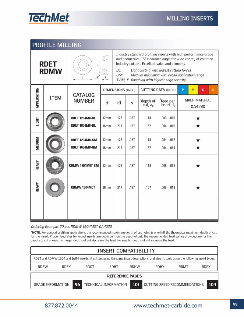
REFERENCE PAGES
GRADE INFORMATION 96 TECHNICAL INFORMATION 101 CUTTING SPEED RECOMMENDATIONS 104
99 877.872.0044 www.techmet-carbide.com
Ordering Example: 20 pcs RDMW 1604M0T GA4230
*NOTE: For general profiling applications the recommended maximum depth of cut noted is one-half the theoretical maximum depth of cut for the insert. Proper feedrates for round inserts are dependent on the depth of cut. The recommended feed values provided are for the depths of cut shown. For larger depths of cut decrease the feed; for smaller depths of cut increase the feed.
PROFILE MILLINGA
PPLI
CATI
ON
ITEM CATALOG NUMBER
DIMENSIONS (INCH) CUTTING DATA (INCH) P M K S
d d1 s depth of cut, ap
feed per insert, fZ
MULTI-MATERIAL
GA4230
LIG
HT RDET 1204M0-BL
RDET 1604M0-BL
12mm
16mm
.173
.217
.187
.187
.118
.157
.003 - .010
.004 - .010
H
H
MED
IUM RDET 1204M0-GM
RDET 1604M0-GM
12mm
16mm
.173
.217
.187
.187
.118
.157
.004 - .012
.004 - .014
H
H
HEA
VY
RDMW 1204M0T-BM 12mm .173 .187 .118 .005 - .015 H
HEA
VY
RDMW 1604M0T 16mm .217 .187 .157 .006 - .018 H
MILLING INSERTS
Industry standard profiling inserts with high performance grade and geometries. 15° clearance angle for wide variety of common industry cutters. Excellent value and economy.
BL: Light cutting with lowest cutting forcesGM: Medium machining with broad application rangeT-BM, T: Roughing with highest edge security
RDETRDMW
INSERT COMPATIBILITYRDET and RDMW 1204 and 1604 inserts fit cutters using the same insert descriptions, and also fit tools using the following insert types:
RDEW RDEX RDGT RDHT RDHW RDHX RDMT RDPX
*
S
d1
15°d
*
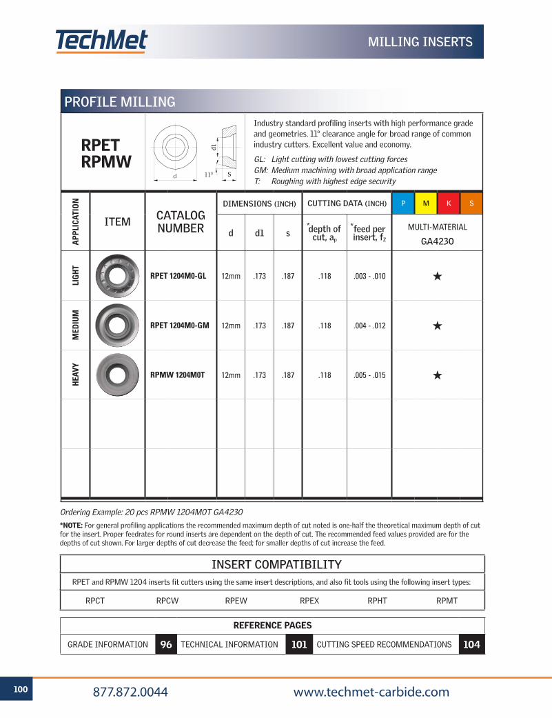
REFERENCE PAGES
GRADE INFORMATION 96 TECHNICAL INFORMATION 101 CUTTING SPEED RECOMMENDATIONS 104
100 877.872.0044 www.techmet-carbide.com
Ordering Example: 20 pcs RPMW 1204M0T GA4230
*NOTE: For general profiling applications the recommended maximum depth of cut noted is one-half the theoretical maximum depth of cut for the insert. Proper feedrates for round inserts are dependent on the depth of cut. The recommended feed values provided are for the depths of cut shown. For larger depths of cut decrease the feed; for smaller depths of cut increase the feed.
PROFILE MILLING
APP
LICA
TIO
N
ITEM CATALOG NUMBER
DIMENSIONS (INCH) CUTTING DATA (INCH) P M K S
d d1 s depth of cut, ap
feed per insert, fZ
MULTI-MATERIAL
GA4230
LIG
HT
RPET 1204M0-GL 12mm .173 .187 .118 .003 - .010 H
MED
IUM
RPET 1204M0-GM 12mm .173 .187 .118 .004 - .012 H
HEA
VY
RPMW 1204M0T 12mm .173 .187 .118 .005 - .015 H
Industry standard profiling inserts with high performance grade and geometries. 11° clearance angle for broad range of common industry cutters. Excellent value and economy.
GL: Light cutting with lowest cutting forcesGM: Medium machining with broad application rangeT: Roughing with highest edge security
RPETRPMW
INSERT COMPATIBILITYRPET and RPMW 1204 inserts fit cutters using the same insert descriptions, and also fit tools using the following insert types:
RPCT RPCW RPEW RPEX RPHT RPMT
S
d1
d 11°
*
MILLING INSERTS
*
Code Key 102
Cutting Speed Recommendations 104
Hardness Comparison Table 106
TECHNICAL INFORMATIONMILLING
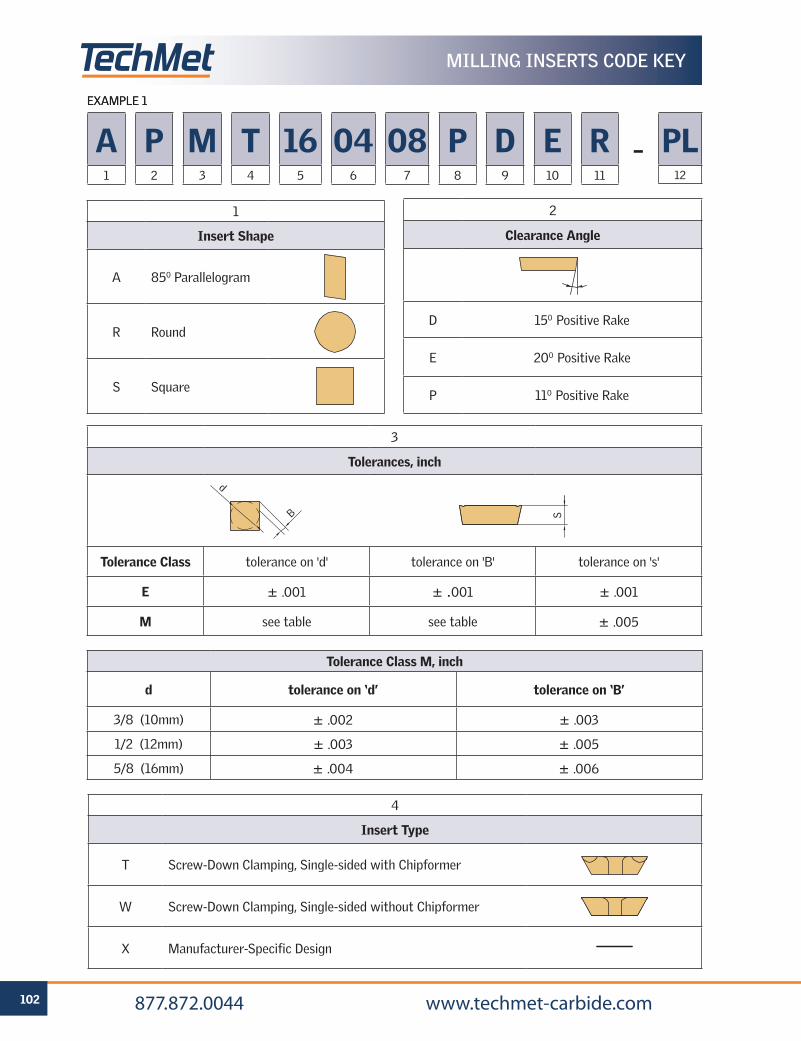
102 877.872.0044 www.techmet-carbide.com
EXAMPLE 1
MILLING INSERTS CODE KEY
EXAMPLE 1
1
Insert Shape
A 850 Parallelogram
R Round
S Square
2
Clearance Angle
D 150 Positive Rake
E 200 Positive Rake
P 110 Positive Rake
3
Tolerances, inch
Tolerance Class tolerance on 'd' tolerance on 'B' tolerance on 's'
E ± .001 ± .001 ± .001
M see table see table ± .005
Tolerance Class M, inch
d tolerance on ‘d’ tolerance on ‘B’
3/8 (10mm) ± .002 ± .003
1/2 (12mm) ± .003 ± .005
5/8 (16mm) ± .004 ± .006
d
B
A1
P2
M3
T4
165
046
087
P8
PL12
–D9
E10
R11
4
Insert Type
T Screw-Down Clamping, Single-sided with Chipformer
W Screw-Down Clamping, Single-sided without Chipformer
X Manufacturer-Specific Design
S
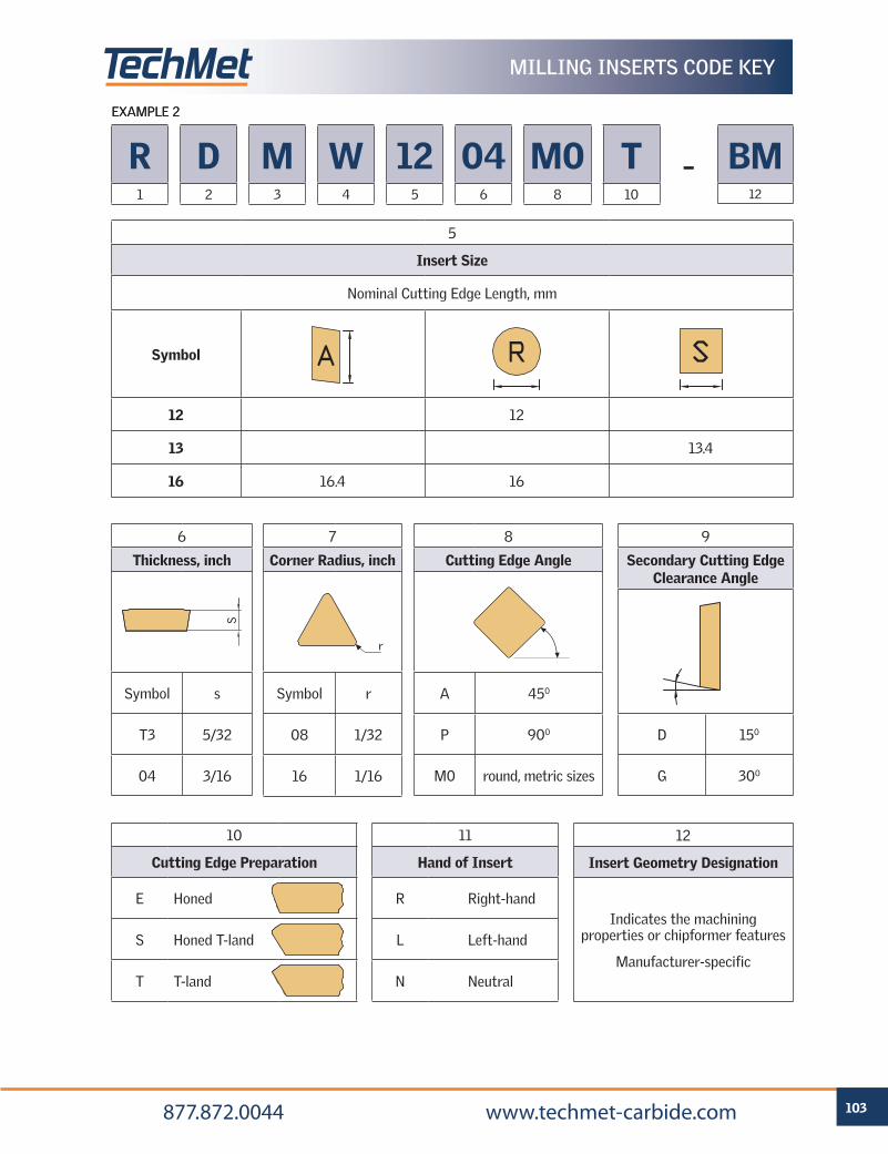
103 877.872.0044 www.techmet-carbide.com
EXAMPLE 2
MILLING INSERTS CODE KEY
R1
D2
M3
W4
125
046
M08
T10
BM12
–
EXAMPLE 2
5
Insert Size
Nominal Cutting Edge Length, mm
Symbol
12 12
13 13.4
16 16.4 16
A R
6
Thickness, inch
Symbol s
T3 5/32
04 3/16
7
Corner Radius, inch
Symbol r
08 1/32
16 1/16
8
Cutting Edge Angle
A 450
P 900
M0 round, metric sizes
r
9
Secondary Cutting EdgeClearance Angle
D 150
G 300
10
Cutting Edge Preparation
E Honed
S Honed T-land
T T-land
11
Hand of Insert
R Right-hand
L Left-hand
N Neutral
12
Insert Geometry Designation
Indicates the machiningproperties or chipformer features
Manufacturer-specific
S
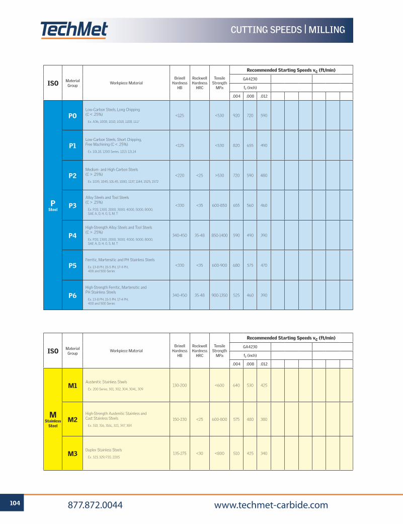
104 877.872.0044 www.techmet-carbide.com
CUTTING SPEEDS | MILLING
ISO Material Group
Workpiece MaterialBrinell
Hardness HB
Rockwell Hardness
HRC
Tensile Strength
MPa
Recommended Starting Speeds vc (ft/min)
GA4230
fz (inch)
.004 .008 .012
P Steel
POLow-Carbon Steels, Long Chipping (C < .25%)
Ex. A36, 1008, 1010, 1018, 1108, 1117
<125 <530 920 720 590
P1Low-Carbon Steels, Short Chipping, Free Machining (C < .25%)
Ex. 10L18, 1200 Series, 1213, 12L14
<125 <530 820 655 490
P2Medium- and High-Carbon Steels (C > .25%)
Ex. 1035, 1045, 10L45, 1080, 1137, 1144, 1525, 1572
<220 <25 >530 720 590 480
P3Alloy Steels and Tool Steels (C > .25%)
Ex. P20, 1300, 2000, 3000, 4000, 5000, 8000, SAE A, D, H, O, S, M, T
<330 <35 600-850 655 560 460
P4High-Strength Alloy Steels and Tool Steels(C > .25%)
Ex. P20, 1300, 2000, 3000, 4000, 5000, 8000, SAE A, D, H, O, S, M, T
340-450 35-48 850-1400 590 490 390
P5Ferritic, Martensitic and PH Stainless Steels
Ex. 13-8 PH, 15-5 PH, 17-4 PH, 400 and 500 Series
<330 <35 600-900 680 575 470
P6High-Strength Ferritic, Martensitic andPH Stainless Steels
Ex. 13-8 PH, 15-5 PH, 17-4 PH, 400 and 500 Series
340-450 35-48 900-1350 525 460 390
ISO Material Group
Workpiece MaterialBrinell
Hardness HB
Rockwell Hardness
HRC
Tensile Strength
MPa
Recommended Starting Speeds vc (ft/min)
GA4230
fz (inch)
.004 .008 .012
M Stainless
Steel
M1Austenitic Stainless Steels
Ex. 200 Series, 301, 302, 304, 304L, 309130-200 <600 640 530 425
M2High-Strength Austenitic Stainless and Cast Stainless Steels
Ex. 310, 316, 316L, 321, 347, 384
150-230 <25 600-800 575 480 380
M3Duplex Stainless Steels
Ex. 323, 329, F55, 2205135-275 <30 <800 510 425 340
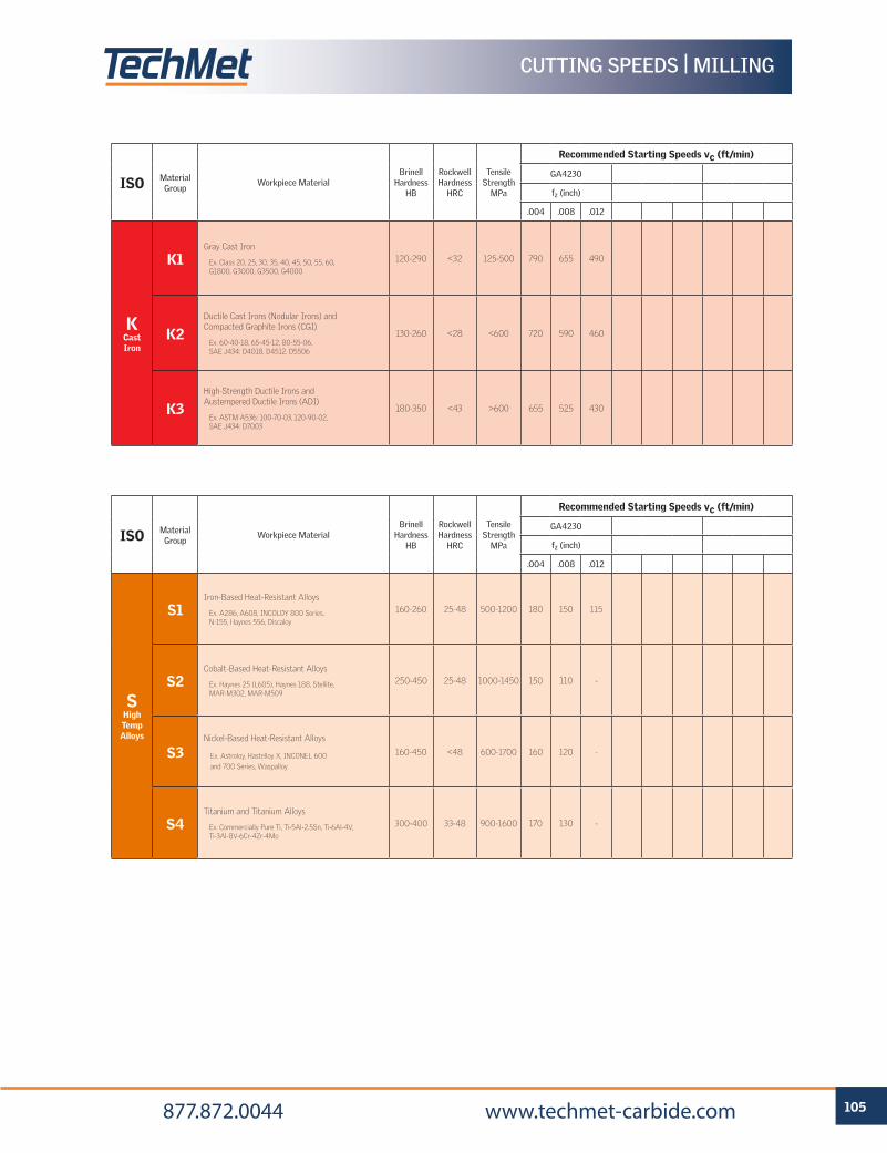
105 877.872.0044 www.techmet-carbide.com
CUTTING SPEEDS | MILLING
ISO Material Group
Workpiece MaterialBrinell
Hardness HB
Rockwell Hardness
HRC
Tensile Strength
MPa
Recommended Starting Speeds vc (ft/min)
GA4230
fz (inch)
.004 .008 .012
K Cast Iron
K1Gray Cast Iron
Ex. Class 20, 25, 30, 35, 40, 45, 50, 55, 60, G1800, G3000, G3500, G4000
120-290 <32 125-500 790 655 490
K2Ductile Cast Irons (Nodular Irons) and Compacted Graphite Irons (CGI)
Ex. 60-40-18, 65-45-12, 80-55-06, SAE J434: D4018, D4512, D5506
130-260 <28 <600 720 590 460
K3High-Strength Ductile Irons and Austempered Ductile Irons (ADI)
Ex. ASTM A536: 100-70-03, 120-90-02, SAE J434: D7003
180-350 <43 >600 655 525 430
ISO Material Group
Workpiece MaterialBrinell
Hardness HB
Rockwell Hardness
HRC
Tensile Strength
MPa
Recommended Starting Speeds vc (ft/min)
GA4230
fz (inch)
.004 .008 .012
S High Temp Alloys
S1Iron-Based Heat-Resistant Alloys
Ex. A286, A608, INCOLOY 800 Series, N-155, Haynes 556, Discaloy
160-260 25-48 500-1200 180 150 115
S2Cobalt-Based Heat-Resistant Alloys
Ex. Haynes 25 (L605), Haynes 188, Stellite, MAR-M302, MAR-M509
250-450 25-48 1000-1450 150 110 -
S3Nickel-Based Heat-Resistant Alloys
Ex. Astroloy, Hastelloy X, INCONEL 600
and 700 Series, Waspalloy
160-450 <48 600-1700 160 120 -
S4Titanium and Titanium Alloys
Ex. Commercially Pure Ti, Ti-5Al-2.5Sn, Ti-6Al-4V, Ti-3Al-8V-6Cr-4Zr-4Mo
300-400 33-48 900-1600 170 130 -
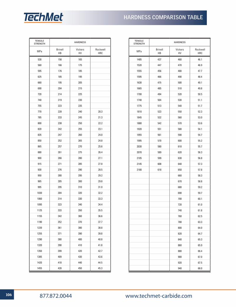
106 877.872.0044 www.techmet-carbide.com
HARDNESS COMPARISON TABLE
TENSILE STRENGTH HARDNESS
MPaBrinell
HBVickers
HVRockwell
HRC
530 156 165
560 166 175
595 176 185
625 185 195
660 195 205
690 204 215
720 214 225
740 219 230
755 223 235
770 228 240 20.3
785 233 245 21.3
800 238 250 22.2
820 242 255 23.1
835 247 260 24.0
850 252 265 24.8
865 257 270 25.6
880 261 275 26.4
900 266 280 27.1
915 271 285 27.8
930 276 290 28.5
950 280 295 29.2
965 285 300 29.8
995 295 310 31.0
1030 304 320 32.2
1060 314 330 33.3
1095 323 340 34.4
1125 333 350 35.5
1155 342 360 36.6
1190 352 370 37.7
1220 361 380 38.8
1255 371 390 39.8
1290 380 400 40.8
1320 390 410 41.8
1350 399 420 42.7
1385 409 430 43.6
1420 418 440 44.5
1455 428 450 45.3
TENSILE STRENGTH HARDNESS
MPaBrinell
HBVickers
HVRockwell
HRC
1485 437 460 46.1
1520 447 470 46.9
1555 456 480 47.7
1595 466 490 48.4
1630 475 500 49.1
1665 485 510 49.8
1700 494 520 50.5
1740 504 530 51.1
1775 513 540 51.7
1810 523 550 52.3
1845 532 560 53.0
1880 542 570 53.6
1920 551 580 54.1
1955 561 590 54.7
1995 570 600 55.2
2030 580 610 55.7
2070 589 620 56.3
2105 599 630 56.8
2145 608 640 57.3
2180 618 650 57.8
660 58.3
670 58.8
680 59.2
690 59.7
700 60.1
720 61.0
740 61.8
760 62.5
780 63.3
800 64.0
820 64.7
840 65.3
860 65.9
880 66.4
900 67.0
920 67.5
940 68.0
Metalcutting SafetyRead before using the tools in this catalog!
Projectile and Fragmentation Hazards:
Modern metalcutting operations involve high spindle and cutter speeds and high temperatures and cutting forces. Hot metal chips may fly off the workpiece during metalcutting. Although cutting tools are designed and manufactured to withstand high cutting forces and temperatures, they can sometimes fragment, particularly if they are subjected to over-stress, severe impact, or other abuse. Many variables affect machining operations. It is impossible to cover every specific situation. The technical information included in this catalog and recommendations on machining practices may not apply to your particular operation. As sold and under normal conditions of use, hardmetal products and tools do not present inhalation, ingestion or other chemical hazards. The health hazards relate only to hardmetal powder. Under normal conditions of use, operations involving hardmetal products and tools do not result in the release of hardmetal powder (either in the form of dusts or fumes) and do not present inhalation, ingestion or other chemical hazards.
To avoid injury:
• Always wear appropriate personal protective equipment, including safety goggles, when operating metalcutting machines or working nearby.
• Always make sure all machine guards are in place.
Breathing and Skin Contact Hazards:
Grinding carbide or other advanced cutting tool materials produces dust or mist containing metallic particles.
To avoid injury:
• If grinding, read the applicable Material Safety Data Sheet and consult General Industry Safety and Health Regulations, Part 1910, Title 29 of the Code of Federal Regulations. These safety instructions are general guidelines.
Although we have attempted to provide current and accurate information herein, we make no representations regarding the accuracy or the completeness of the information and assume no liability for any loss, damage, or injury of any kind which may result from or arise out of the use of or reliance on the information by any person.
Cata
log
0920
01
877.872.0044 www.techmet-carbide.com
PRO
DU
CTH
AN
DBO
OK
TURN
ING
GRO
OV
ING
TH
REA
DIN
GM
ILLI
NG