Embed Size (px)
Citation preview
February 1, 2010 / Vol. 35, No. 3 / OPTICS LETTERS 327
Tunable micro-optofluidic prism based onliquid-core liquid-cladding configuration
Chaolong Song, Nam-Trung Nguyen,* Anand Krishna Asundi, and Say-Hwa TanSchool of Mechanical and Aerospace Engineering, Nanyang Technological University,
50 Nanyang Avenue, Singapore 639798, Singapore*Corresponding author: [email protected]
Received November 6, 2009; revised December 21, 2009; accepted December 22, 2009;posted January 4, 2010 (Doc. ID 119552); published January 25, 2010
The integration of optical components into microfluidic systems has the potential to reduce the amount ofbulky external devices and thus reduce the cost. However, one of the challenges of this concept is the accu-rate alignment of the optical path among multiple optical components inside a chip. We propose a tunablemicro-optofluidic prism based on the liquid-core liquid-cladding structure formed in a sector-shape chamber.The optical interface of the prism is maintained in a straight line shape by distributing a row of pressurebarriers in the chamber. By adjusting the flow rate ratio between core and cladding streams, the apex angleof the prism can be tuned accordingly. As a consequence, the deviation angle of the light beam refracted bythe prism can be changed continuously. This tunability of our optofluidic prism can be utilized for the align-ment of the optical path inside a chip or for the development of optical switches. © 2010 Optical Society ofAmerica
OCIS codes: 230.3990, 230.4685, 050.1965, 080.3620.
The combination of microfluidics and optics has en-abled the miniaturization and tunability of opto-fluidic devices for lab-on-chip systems. The miniatur-ization and integration of optical components prom-ise the potential of reducing the amount of bulky ex-ternal devices and the alignment of multiplecomponents in a single chip. One challenging prob-lem is the alignment of the optical path among mul-tiple integrated components. Moreover, precise ad-justment of the optical path is critically important forinterferometer sensors [1] and multiple-prism laserpulse compressors [2], especially when they are inte-grated into a chip. The laminar flow-based liquid-coreliquid-cladding configuration has been widely appliedto configure optical components in versatile ways. Onthe one hand, the interface between two immisciblefluids is atomically smooth, which can be utilized inreflection or refraction of light. On the other hand,two miscible fluids can create an index-gradient dis-tribution, which can modulate the propagation oflight inside the fluids. Recently, optical waveguides[3,4], reconfigurable lenses [5–9], and opticalswitches [10] based on this configuration have beendemonstrated.
In this Letter, we propose a tunable micro-optofluidic prism, which is hydrodynamically formedby one core and two cladding streams inside a sector-shape chamber (Fig. 1). Benzyl alcohol (viscosity �=5�10−3 Pa s at 25°C) with a refractive index of1.536 is employed as the core stream, which formsthe geometry of a triangular prism. A mixture (vis-cosity �=9�10−3 Pa s at 25°C) of glycerol (60% byweight) and water (40% by weight) with a refractiveindex of n=1.412 matching that of polydimethylsilox-ane (PDMS) serves as cladding streams. Owing to thehigher refractive index of the core stream, this con-figuration can perform a prism function. The apexangle of this optofluidic prism can be tuned by adjust-
ing the flow rate ratio between core and cladding0146-9592/10/030327-3/$15.00 ©
streams, and therefore the deviation angle of an inci-dent light beam can be changed accordingly. Sincethe propagation direction of a refracted light beamcan be accurately controlled by choosing a properflow rate ratio, this tunable prism can continuouslyscan the light beam and therefore can be engaged inthe alignment of the optical path or in the develop-ment of optical switches.
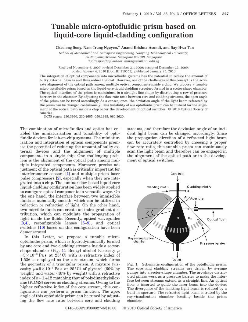
Fig. 1. Schematic configuration of the optofluidic prism.The core and cladding streams are driven by syringepumps into a sector-shape chamber. The arc-shape distrib-uted pillars work as a pressure barrier to make the inter-face between streams extend as a straight line. An opticalfiber is inserted to guide the laser beam into the device.The divergence of the emitting light beam is reduced by abuilt-in aperture. The refracted light beam is traced by theray-visualization chamber locating beside the prism
chamber.2010 Optical Society of America
328 OPTICS LETTERS / Vol. 35, No. 3 / February 1, 2010
Our device was fabricated in PDMS by using astandard soft lithography technique. The configura-tion of our tunable prism is based on three streams oflaminar flows in a sector-shape chamber, which has a90° opening angle (Fig. 1) and a channel depth of150 �m. In the chamber, an array of pillars distrib-uted in an arc and located at a distance of 3.5 mmfrom the inlet serves as pressure barriers. The angu-lar interval between each pillar is 1.5°. The entranceof the sector-shape chamber with a width of 300 �mis much smaller than the radius of the chamber. Thesmall gaps between the pillars are supposed to makethe pressure drop equally distributed along the arcwhere the pillars stand. Therefore, the entrance ofthe chamber and the arc consisting of the gaps actapproximately as a source–sink pair bounded withina divergent boundary with a 90° opening angle. Thestreamlines inside a source–sink pair domain have asimilarity in shape with the boundary [7]. Thus theinterfaces between the core and the cladding streamsare theoretically radiating lines from the source. Thisfact was confirmed experimentally (insets in Fig. 2).Because of the even distribution of the pressure atthe pillars, the flow flux through the gaps is assumedto be equally distributed. Therefore, the apex anglecan be derived as a function of the flow rate ratiobased on the theory of the liquid-core liquid-claddingsystem reported in [10]:
� = 90 ° ��
� + 2�, �1�
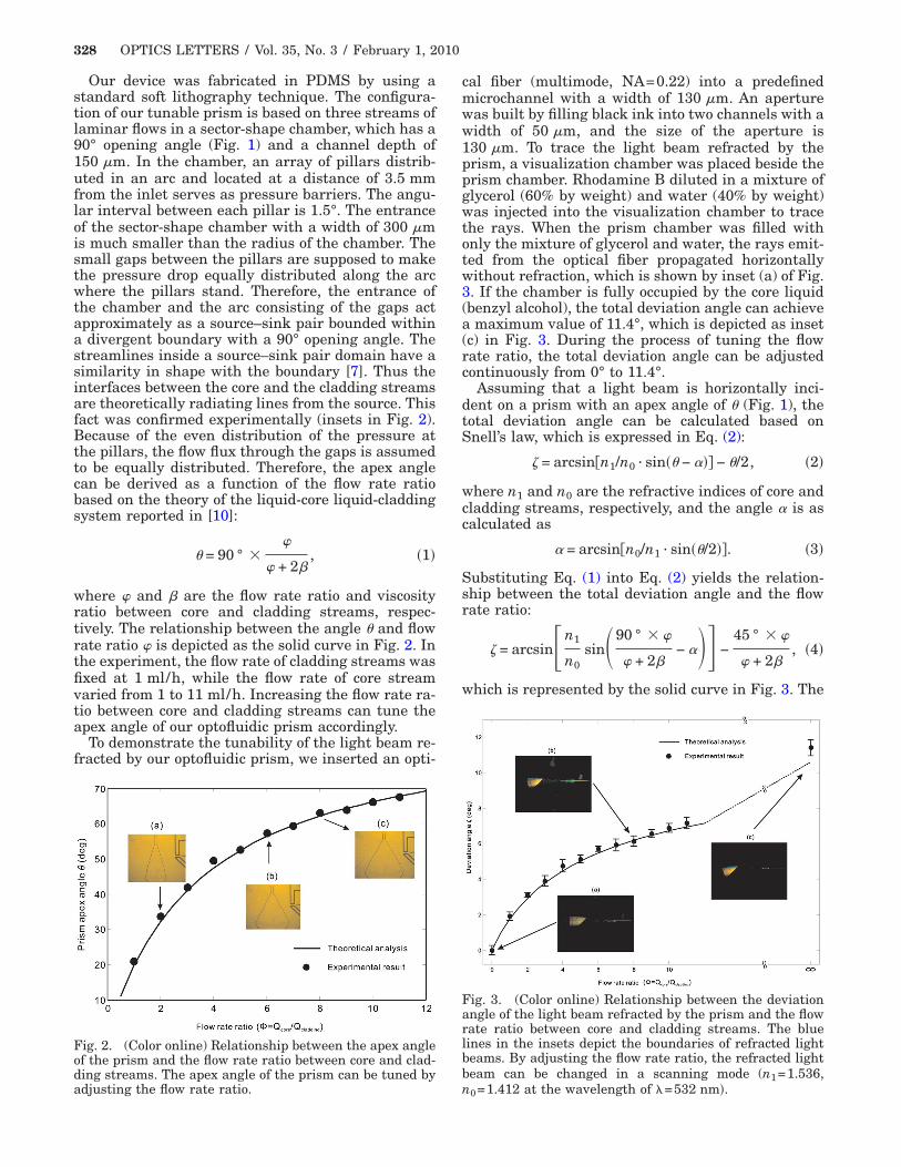
where � and � are the flow rate ratio and viscosityratio between core and cladding streams, respec-tively. The relationship between the angle � and flowrate ratio � is depicted as the solid curve in Fig. 2. Inthe experiment, the flow rate of cladding streams wasfixed at 1 ml/h, while the flow rate of core streamvaried from 1 to 11 ml/h. Increasing the flow rate ra-tio between core and cladding streams can tune theapex angle of our optofluidic prism accordingly.
To demonstrate the tunability of the light beam re-fracted by our optofluidic prism, we inserted an opti-
Fig. 2. (Color online) Relationship between the apex angleof the prism and the flow rate ratio between core and clad-ding streams. The apex angle of the prism can be tuned by
adjusting the flow rate ratio.cal fiber (multimode, NA=0.22) into a predefinedmicrochannel with a width of 130 �m. An aperturewas built by filling black ink into two channels with awidth of 50 �m, and the size of the aperture is130 �m. To trace the light beam refracted by theprism, a visualization chamber was placed beside theprism chamber. Rhodamine B diluted in a mixture ofglycerol (60% by weight) and water (40% by weight)was injected into the visualization chamber to tracethe rays. When the prism chamber was filled withonly the mixture of glycerol and water, the rays emit-ted from the optical fiber propagated horizontallywithout refraction, which is shown by inset (a) of Fig.3. If the chamber is fully occupied by the core liquid(benzyl alcohol), the total deviation angle can achievea maximum value of 11.4°, which is depicted as inset(c) in Fig. 3. During the process of tuning the flowrate ratio, the total deviation angle can be adjustedcontinuously from 0° to 11.4°.
Assuming that a light beam is horizontally inci-dent on a prism with an apex angle of � (Fig. 1), thetotal deviation angle can be calculated based onSnell’s law, which is expressed in Eq. (2):
� = arcsin�n1/n0 · sin�� − ��� − �/2, �2�
where n1 and n0 are the refractive indices of core andcladding streams, respectively, and the angle � is ascalculated as
� = arcsin�n0/n1 · sin��/2��. �3�
Substituting Eq. (1) into Eq. (2) yields the relation-ship between the total deviation angle and the flowrate ratio:
� = arcsin�n1
n0sin�90 ° � �
� + 2�− ��� −
45 ° � �
� + 2�, �4�
which is represented by the solid curve in Fig. 3. The
Fig. 3. (Color online) Relationship between the deviationangle of the light beam refracted by the prism and the flowrate ratio between core and cladding streams. The bluelines in the insets depict the boundaries of refracted lightbeams. By adjusting the flow rate ratio, the refracted lightbeam can be changed in a scanning mode (n1=1.536,
n0=1.412 at the wavelength of �=532 nm�.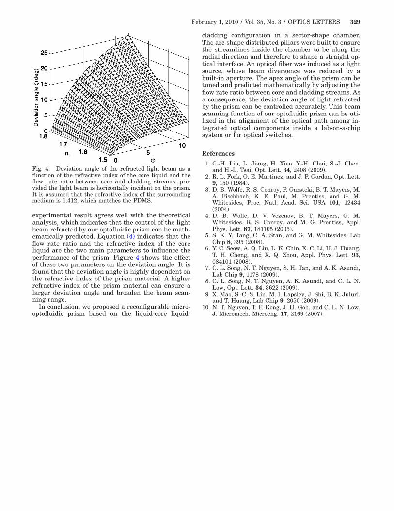
February 1, 2010 / Vol. 35, No. 3 / OPTICS LETTERS 329
experimental result agrees well with the theoreticalanalysis, which indicates that the control of the lightbeam refracted by our optofluidic prism can be math-ematically predicted. Equation (4) indicates that theflow rate ratio and the refractive index of the coreliquid are the two main parameters to influence theperformance of the prism. Figure 4 shows the effectof these two parameters on the deviation angle. It isfound that the deviation angle is highly dependent onthe refractive index of the prism material. A higherrefractive index of the prism material can ensure alarger deviation angle and broaden the beam scan-ning range.
In conclusion, we proposed a reconfigurable micro-
Fig. 4. Deviation angle of the refracted light beam as afunction of the refractive index of the core liquid and theflow rate ratio between core and cladding streams, pro-vided the light beam is horizontally incident on the prism.It is assumed that the refractive index of the surroundingmedium is 1.412, which matches the PDMS.
optofluidic prism based on the liquid-core liquid-
cladding configuration in a sector-shape chamber.The arc-shape distributed pillars were built to ensurethe streamlines inside the chamber to be along theradial direction and therefore to shape a straight op-tical interface. An optical fiber was induced as a lightsource, whose beam divergence was reduced by abuilt-in aperture. The apex angle of the prism can betuned and predicted mathematically by adjusting theflow rate ratio between core and cladding streams. Asa consequence, the deviation angle of light refractedby the prism can be controlled accurately. This beamscanning function of our optofluidic prism can be uti-lized in the alignment of the optical path among in-tegrated optical components inside a lab-on-a-chipsystem or for optical switches.
References
1. C.-H. Lin, L. Jiang, H. Xiao, Y.-H. Chai, S.-J. Chen,and H.-L. Tsai, Opt. Lett. 34, 2408 (2009).
2. R. L. Fork, O. E. Martinez, and J. P. Gordon, Opt. Lett.9, 150 (1984).
3. D. B. Wolfe, R. S. Conroy, P. Garsteki, B. T. Mayers, M.A. Fischbach, K. E. Paul, M. Prentiss, and G. M.Whitesides, Proc. Natl. Acad. Sci. USA 101, 12434(2004).
4. D. B. Wolfe, D. V. Vezenov, B. T. Mayers, G. M.Whitesides, R. S. Conroy, and M. G. Prentiss, Appl.Phys. Lett. 87, 181105 (2005).
5. S. K. Y. Tang, C. A. Stan, and G. M. Whitesides, LabChip 8, 395 (2008).
6. Y. C. Seow, A. Q. Liu, L. K. Chin, X. C. Li, H. J. Huang,T. H. Cheng, and X. Q. Zhou, Appl. Phys. Lett. 93,084101 (2008).
7. C. L. Song, N. T. Nguyen, S. H. Tan, and A. K. Asundi,Lab Chip 9, 1178 (2009).
8. C. L. Song, N. T. Nguyen, A. K. Asundi, and C. L. N.Low, Opt. Lett. 34, 3622 (2009).
9. X. Mao, S.-C. S. Lin, M. I. Lapsley, J. Shi, B. K. Juluri,and T. Huang, Lab Chip 9, 2050 (2009).
10. N. T. Nguyen, T. F. Kong, J. H. Goh, and C. L. N. Low,
J. Micromech. Microeng. 17, 2169 (2007).

![Refractive index measurement through image analysis with an … · 2018-02-07 · of optofluidic devices capable of measuring the refractive index of liquid solutions [6–10]. Here](https://img.pdfslide.us/doc/110x75/5e55b1481950253fc1156184/refractive-index-measurement-through-image-analysis-with-an-2018-02-07-of-optofluidic.jpg)