Embed Size (px)
Citation preview
micromachines
Article
Lorentz Force Actuated Tunable-Focus Liquid Lens
Kari L. Van Grinsven 1,†, Alireza Ousati Ashtiani 1,† and Hongrui Jiang 1,2,3,4,5,*1 Department of Electrical and Computer Engineering, University of Wisconsin-Madison,
Madison, WI 53706, USA; [email protected] (K.L.V.G.); [email protected] (A.O.A.)2 Department of Materials Science and Engineering, University of Wisconsin-Madison,
Madison, WI 53706, USA3 Department of Ophthalmology and Visual Sciences, University of Wisconsin-Madison,
Madison, WI 53706, USA4 Department of Biomedical Engineering, University of Wisconsin-Madison, Madison, WI 53706, USA5 McPherson Eye Research Institute, University of Wisconsin-Madison, Madison, WI 53706, USA* Correspondence: [email protected]; Tel.: +1-608-265-9418† These authors contributed equally to this work.
Received: 8 October 2019; Accepted: 21 October 2019; Published: 22 October 2019�����������������
Abstract: Tunable-focus liquid lenses provide focal length tuning for optical systems, e.g., cameras,where physical movement of rigid lenses are not an option or not preferable. In this work we presenta magnetically actuated liquid lens utilizing the Lorentz force to vary the focal length as the currentthrough the system is varied. The resulting lens can operate as both a diverging and a converging lensdepending on the direction of current applied and has a large range of focal lengths, from −305 mmto –111 mm and from 272 mm to 146 mm. We also characterized the aberrations of the lens during theactuation with a Shack–Hartmann wavefront sensor, and utilized the lens for imaging, during whichwe measured a resolution of 7.13 lp/mm.
Keywords: tunable lens; liquid lens; magnetic actuator; optofluidics
1. Introduction
Tunable lenses are a class of optical lenses that provide adjustable focal lengths, as comparedto the fixed focal lengths found in traditional solid lenses. This tunability provides an extra degreeof freedom for designers of optical devices. In addition, imaging devices with a tunable lens do notneed a translational lens movement to focus, as the focusing can be done by tuning the focal lengthitself. Not having a moving lens barrel found in most of traditional imaging devices results in a fasterresponse time, a more compact package, and a robust device structure [1]. To realize focus tunability,various mechanisms, for example, liquid crystal [2–4], polymer [5–7], and most frequently, liquid-filledfocus tunable lenses [1], have been proposed and used.
Tunable-focus liquid lenses utilize the different indices of refraction of different liquids in order toform a lens at the interface of these two liquids. Generally, this is done in one of two ways, either byusing two immiscible liquids or by employing a membrane. In the case of a membrane, the membranemay be used between liquid and air, or between two different liquids. While liquid lenses withouta membrane generally rely upon electromagnetic or thermal properties of the liquids themselves in orderto actuate the lens [8–14], liquid lenses formed with the addition of a simple membrane can be actuatedthrough a much wider range of mechanisms. Thanks to the near-incompressibility of liquids, theselenses can utilize a variety of different actuators, including pneumatic [15–19], electrowetting [20–24],magnetic/electromagnetic [25,26], piezoelectric [27–32], electrostatic [33], dielectrophoretic [11,34],or any other actuator that can be coupled to a sealed liquid chamber to provide focus tuning.Electromagnetic actuators are particularly appealing because they can enable extremely fast response
Micromachines 2019, 10, 714; doi:10.3390/mi10100714 www.mdpi.com/journal/micromachines
Micromachines 2019, 10, 714 2 of 13
times on the order of 2–3 ms [35,36]. Electromagnetic actuators can also apply large enough forces toa system to enable relatively large deformation of the membrane that defines the lens, and these largedeformations translate into a larger range of potential focal lengths of the liquid lens.
Using electromagnetism and taking advantage of the inherent relationship between electricityand magnetism in order to achieve linear actuation has been taking place for decades. It is the basisof such well-established technology like the voice coil actuator, which utilizes an electrical coil anda permanent magnet to translate the movable portion of the system into a piston motion [25,26,37].Electromagnetism has been used as the actuating force for a number of different kinds of tunable lensesand optical systems as well, though there is a large variety of configurations of electromagnet/wiringand permanent magnet [38–40]. Some designs use a membrane to transfer the actuation from one regionof a chamber to another in order to ensure a clear optical path for the lens. In our design, we haveimplemented a simple magnetic actuator that relies on radial magnetic field, which reduces thecomplexity of the magnetic circuit that we will describe next.
2. Actuation Mechanism
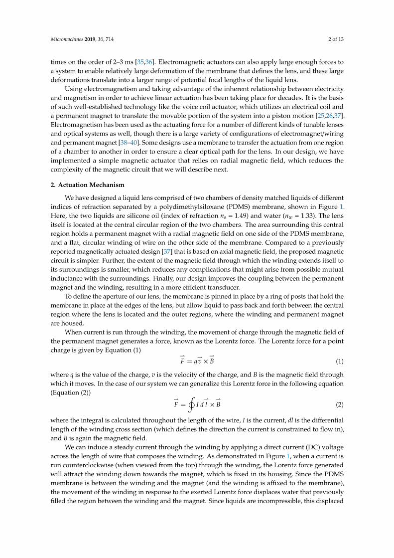
We have designed a liquid lens comprised of two chambers of density matched liquids of differentindices of refraction separated by a polydimethylsiloxane (PDMS) membrane, shown in Figure 1.Here, the two liquids are silicone oil (index of refraction ns = 1.49) and water (nw = 1.33). The lensitself is located at the central circular region of the two chambers. The area surrounding this centralregion holds a permanent magnet with a radial magnetic field on one side of the PDMS membrane,and a flat, circular winding of wire on the other side of the membrane. Compared to a previouslyreported magnetically actuated design [37] that is based on axial magnetic field, the proposed magneticcircuit is simpler. Further, the extent of the magnetic field through which the winding extends itself toits surroundings is smaller, which reduces any complications that might arise from possible mutualinductance with the surroundings. Finally, our design improves the coupling between the permanentmagnet and the winding, resulting in a more efficient transducer.
To define the aperture of our lens, the membrane is pinned in place by a ring of posts that hold themembrane in place at the edges of the lens, but allow liquid to pass back and forth between the centralregion where the lens is located and the outer regions, where the winding and permanent magnetare housed.
When current is run through the winding, the movement of charge through the magnetic field ofthe permanent magnet generates a force, known as the Lorentz force. The Lorentz force for a pointcharge is given by Equation (1)
⇀F = q
⇀v ×
⇀B (1)
where q is the value of the charge, v is the velocity of the charge, and B is the magnetic field throughwhich it moves. In the case of our system we can generalize this Lorentz force in the following equation(Equation (2))
⇀F =
∮I d⇀l ×
⇀B (2)
where the integral is calculated throughout the length of the wire, I is the current, dl is the differentiallength of the winding cross section (which defines the direction the current is constrained to flow in),and B is again the magnetic field.
We can induce a steady current through the winding by applying a direct current (DC) voltageacross the length of wire that composes the winding. As demonstrated in Figure 1, when a current isrun counterclockwise (when viewed from the top) through the winding, the Lorentz force generatedwill attract the winding down towards the magnet, which is fixed in its housing. Since the PDMSmembrane is between the winding and the magnet (and the winding is affixed to the membrane),the movement of the winding in response to the exerted Lorentz force displaces water that previouslyfilled the region between the winding and the magnet. Since liquids are incompressible, this displaced
Micromachines 2019, 10, 714 3 of 13
volume of water is simply transferred to the central region of the chamber, where the membrane bulgesupwards by a volume equal to the volume displaced by the attractive force to form the lens, as seenin Figure 1b. Since the index of refraction of silicone oil is greater than that of water (1.49 and 1.33,respectively), a diverging lens is formed.
Micromachines 2019, 10, x 3 of 13
the lens, as seen in Figure 1b. Since the index of refraction of silicone oil is greater than that of water (1.49 and 1.33, respectively), a diverging lens is formed.
Figure 1. (a) Cross section of the magnetically actuated liquid tunable lens. Radial magnetic fields are shown as dashed lines and arrows in the magnet show the direction of the field. The cross and dot in the winding show current direction (into page and out of page, respectively). (b) The lens in the actuated state, showing a deformed membrane in the middle, which forms the liquid lens in the presence of electrical current.
If the direction of the current is reversed (i.e., if it is applied to run in a clockwise direction), then the cross product means that the direction of the Lorentz force is reversed as well, and the winding is repelled by the permanent magnet instead of attracted to it. This displaces the silicone oil in the region of the chamber above the winding into the central section of the chamber, causing the membrane to bulge downwards there. This results in a converging lens. Thus, the power of the lens is correlated to the amount of current running through the winding, where higher current leads to a higher-power lens, and the sign of the lens (whether it is diverging or converging) is determined by the direction of the current.
Other factors that will affect the power of the lens at a given current are the strength of the magnetic field, which depends on the material/strength of the permanent magnet, and the distance of the winding from that magnet. The thickness of the PDMS membrane will also affect the power of the lens, since a thicker membrane will be stiffer, and thus require a stronger force to bend. Finally, the amount of current that we can run through our winding will be limited by ohmic heating. In our design, we have tried to carefully balance these different factors.
3. Fabrication
In order to fabricate the lens, we chose to make the lens housing via 3D printing. Specifically, we used a stereolithography (SLA) 3D printer that has the ability to print photopolymer resin with an XY resolution of 150 μm and a layer thickness of 100 μm (Form 2, Formlabs Inc., Somerville, MA, USA). The lens housing consists of two separate 3D prints, the upper chamber, and the lower chamber (see Figure 2). The primary difference between the upper and lower chamber is that the lower
Figure 1. (a) Cross section of the magnetically actuated liquid tunable lens. Radial magnetic fieldsare shown as dashed lines and arrows in the magnet show the direction of the field. The cross anddot in the winding show current direction (into page and out of page, respectively). (b) The lens inthe actuated state, showing a deformed membrane in the middle, which forms the liquid lens in thepresence of electrical current.
If the direction of the current is reversed (i.e., if it is applied to run in a clockwise direction), thenthe cross product means that the direction of the Lorentz force is reversed as well, and the winding isrepelled by the permanent magnet instead of attracted to it. This displaces the silicone oil in the regionof the chamber above the winding into the central section of the chamber, causing the membrane tobulge downwards there. This results in a converging lens. Thus, the power of the lens is correlated tothe amount of current running through the winding, where higher current leads to a higher-powerlens, and the sign of the lens (whether it is diverging or converging) is determined by the direction ofthe current.
Other factors that will affect the power of the lens at a given current are the strength of themagnetic field, which depends on the material/strength of the permanent magnet, and the distance ofthe winding from that magnet. The thickness of the PDMS membrane will also affect the power ofthe lens, since a thicker membrane will be stiffer, and thus require a stronger force to bend. Finally,the amount of current that we can run through our winding will be limited by ohmic heating. In ourdesign, we have tried to carefully balance these different factors.
3. Fabrication
In order to fabricate the lens, we chose to make the lens housing via 3D printing. Specifically,we used a stereolithography (SLA) 3D printer that has the ability to print photopolymer resin with
Micromachines 2019, 10, 714 4 of 13
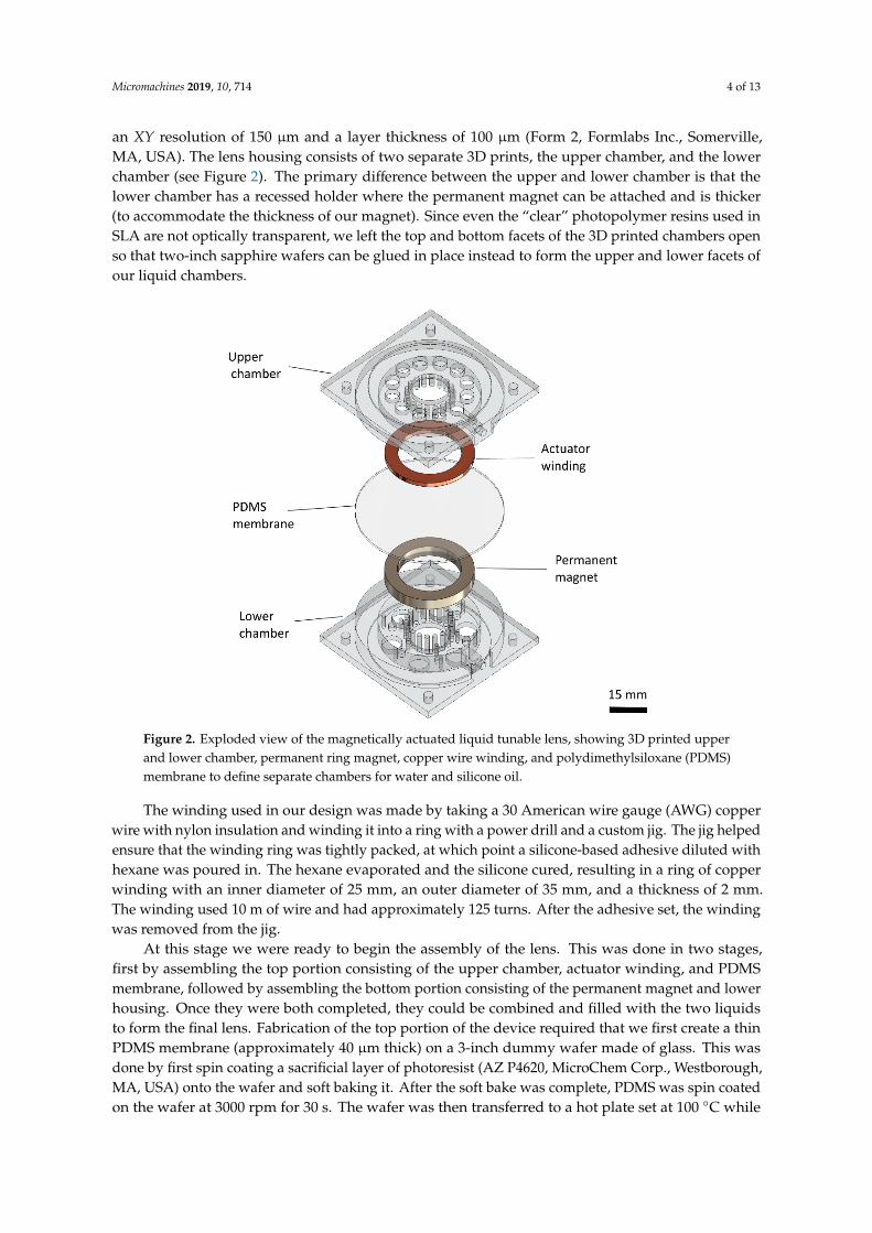
an XY resolution of 150 µm and a layer thickness of 100 µm (Form 2, Formlabs Inc., Somerville,MA, USA). The lens housing consists of two separate 3D prints, the upper chamber, and the lowerchamber (see Figure 2). The primary difference between the upper and lower chamber is that thelower chamber has a recessed holder where the permanent magnet can be attached and is thicker(to accommodate the thickness of our magnet). Since even the “clear” photopolymer resins used inSLA are not optically transparent, we left the top and bottom facets of the 3D printed chambers openso that two-inch sapphire wafers can be glued in place instead to form the upper and lower facets ofour liquid chambers.
Micromachines 2019, 10, x 4 of 13
chamber has a recessed holder where the permanent magnet can be attached and is thicker (to accommodate the thickness of our magnet). Since even the “clear” photopolymer resins used in SLA are not optically transparent, we left the top and bottom facets of the 3D printed chambers open so that two-inch sapphire wafers can be glued in place instead to form the upper and lower facets of our liquid chambers.
The winding used in our design was made by taking a 30 American wire gauge (AWG) copper wire with nylon insulation and winding it into a ring with a power drill and a custom jig. The jig helped ensure that the winding ring was tightly packed, at which point a silicone-based adhesive diluted with hexane was poured in. The hexane evaporated and the silicone cured, resulting in a ring of copper winding with an inner diameter of 25 mm, an outer diameter of 35 mm, and a thickness of 2 mm. The winding used 10 m of wire and had approximately 125 turns. After the adhesive set, the winding was removed from the jig.
At this stage we were ready to begin the assembly of the lens. This was done in two stages, first by assembling the top portion consisting of the upper chamber, actuator winding, and PDMS membrane, followed by assembling the bottom portion consisting of the permanent magnet and lower housing. Once they were both completed, they could be combined and filled with the two liquids to form the final lens. Fabrication of the top portion of the device required that we first create a thin PDMS membrane (approximately 40 μm thick) on a 3-inch dummy wafer made of glass. This was done by first spin coating a sacrificial layer of photoresist (AZ P4620, MicroChem Corp., Westborough, MA, USA) onto the wafer and soft baking it. After the soft bake was complete, PDMS was spin coated on the wafer at 3000 rpm for 30 s. The wafer was then transferred to a hot plate set at 100 °C while the PDMS cured. Once the PDMS membrane had fully cured, the actuator winding was glued to the central portion of the membrane using a silicone adhesive (Sil-Poxy, Smooth-On, Macungie, PA, USA). The PDMS and winding on the dummy wafer were then fit into the upper chamber of the housing, and the outer rim that defined the upper liquid chamber was also affixed to the PDMS membrane using Sil-Poxy. This step can be seen in Figure 3a.
Figure 2. Exploded view of the magnetically actuated liquid tunable lens, showing 3D printed upper and lower chamber, permanent ring magnet, copper wire winding, and polydimethylsiloxane (PDMS) membrane to define separate chambers for water and silicone oil.
Figure 2. Exploded view of the magnetically actuated liquid tunable lens, showing 3D printed upperand lower chamber, permanent ring magnet, copper wire winding, and polydimethylsiloxane (PDMS)membrane to define separate chambers for water and silicone oil.
The winding used in our design was made by taking a 30 American wire gauge (AWG) copperwire with nylon insulation and winding it into a ring with a power drill and a custom jig. The jig helpedensure that the winding ring was tightly packed, at which point a silicone-based adhesive diluted withhexane was poured in. The hexane evaporated and the silicone cured, resulting in a ring of copperwinding with an inner diameter of 25 mm, an outer diameter of 35 mm, and a thickness of 2 mm.The winding used 10 m of wire and had approximately 125 turns. After the adhesive set, the windingwas removed from the jig.
At this stage we were ready to begin the assembly of the lens. This was done in two stages,first by assembling the top portion consisting of the upper chamber, actuator winding, and PDMSmembrane, followed by assembling the bottom portion consisting of the permanent magnet and lowerhousing. Once they were both completed, they could be combined and filled with the two liquidsto form the final lens. Fabrication of the top portion of the device required that we first create a thinPDMS membrane (approximately 40 µm thick) on a 3-inch dummy wafer made of glass. This wasdone by first spin coating a sacrificial layer of photoresist (AZ P4620, MicroChem Corp., Westborough,MA, USA) onto the wafer and soft baking it. After the soft bake was complete, PDMS was spin coatedon the wafer at 3000 rpm for 30 s. The wafer was then transferred to a hot plate set at 100 ◦C while
Micromachines 2019, 10, 714 5 of 13
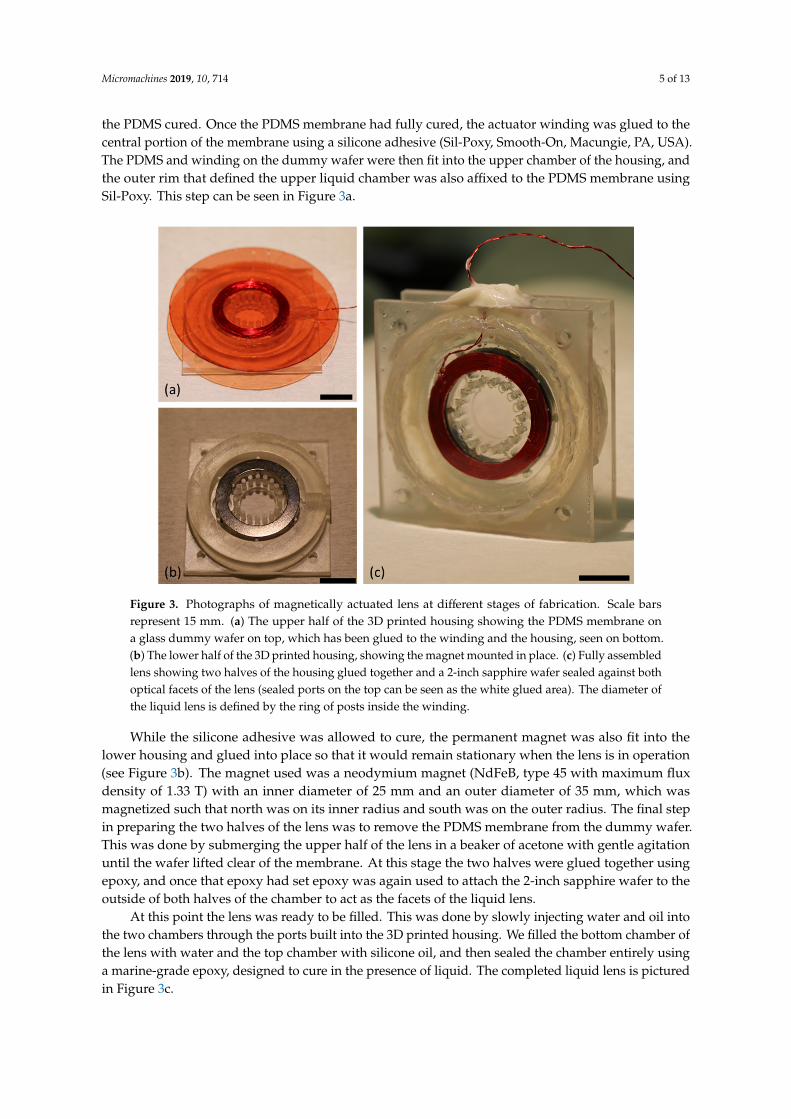
the PDMS cured. Once the PDMS membrane had fully cured, the actuator winding was glued to thecentral portion of the membrane using a silicone adhesive (Sil-Poxy, Smooth-On, Macungie, PA, USA).The PDMS and winding on the dummy wafer were then fit into the upper chamber of the housing, andthe outer rim that defined the upper liquid chamber was also affixed to the PDMS membrane usingSil-Poxy. This step can be seen in Figure 3a.
Micromachines 2019, 10, x 5 of 13
While the silicone adhesive was allowed to cure, the permanent magnet was also fit into the lower housing and glued into place so that it would remain stationary when the lens is in operation (see Figure 3b). The magnet used was a neodymium magnet (NdFeB, type 45 with maximum flux density of 1.33 T) with an inner diameter of 25 mm and an outer diameter of 35 mm, which was magnetized such that north was on its inner radius and south was on the outer radius. The final step in preparing the two halves of the lens was to remove the PDMS membrane from the dummy wafer. This was done by submerging the upper half of the lens in a beaker of acetone with gentle agitation until the wafer lifted clear of the membrane. At this stage the two halves were glued together using epoxy, and once that epoxy had set epoxy was again used to attach the 2-inch sapphire wafer to the outside of both halves of the chamber to act as the facets of the liquid lens.
At this point the lens was ready to be filled. This was done by slowly injecting water and oil into the two chambers through the ports built into the 3D printed housing. We filled the bottom chamber of the lens with water and the top chamber with silicone oil, and then sealed the chamber entirely using a marine-grade epoxy, designed to cure in the presence of liquid. The completed liquid lens is pictured in Figure 3c.
Figure 3. Photographs of magnetically actuated lens at different stages of fabrication. Scale bars represent 15 mm. (a) The upper half of the 3D printed housing showing the PDMS membrane on a glass dummy wafer on top, which has been glued to the winding and the housing, seen on bottom. (b) The lower half of the 3D printed housing, showing the magnet mounted in place. (c) Fully assembled lens showing two halves of the housing glued together and a 2-inch sapphire wafer sealed against both optical facets of the lens (sealed ports on the top can be seen as the white glued area). The diameter of the liquid lens is defined by the ring of posts inside the winding.
4. Results
In order to characterize our magnetically actuated liquid lens, we first measured the focal length versus voltage. We chose to report applied voltages instead of applied current because we used a DC voltage source for our experiments (Agilent E3644A); however, the current follows the voltage very linearly by the well-known relation I = V/R, where the resistance of our system (the resistance of the copper winding) can be considered a constant for our purposes. In order to make measurements of the focal length of the lens, we needed a single setup that could measure the focal length of both a
Figure 3. Photographs of magnetically actuated lens at different stages of fabrication. Scale barsrepresent 15 mm. (a) The upper half of the 3D printed housing showing the PDMS membrane ona glass dummy wafer on top, which has been glued to the winding and the housing, seen on bottom.(b) The lower half of the 3D printed housing, showing the magnet mounted in place. (c) Fully assembledlens showing two halves of the housing glued together and a 2-inch sapphire wafer sealed against bothoptical facets of the lens (sealed ports on the top can be seen as the white glued area). The diameter ofthe liquid lens is defined by the ring of posts inside the winding.
While the silicone adhesive was allowed to cure, the permanent magnet was also fit into thelower housing and glued into place so that it would remain stationary when the lens is in operation(see Figure 3b). The magnet used was a neodymium magnet (NdFeB, type 45 with maximum fluxdensity of 1.33 T) with an inner diameter of 25 mm and an outer diameter of 35 mm, which wasmagnetized such that north was on its inner radius and south was on the outer radius. The final stepin preparing the two halves of the lens was to remove the PDMS membrane from the dummy wafer.This was done by submerging the upper half of the lens in a beaker of acetone with gentle agitationuntil the wafer lifted clear of the membrane. At this stage the two halves were glued together usingepoxy, and once that epoxy had set epoxy was again used to attach the 2-inch sapphire wafer to theoutside of both halves of the chamber to act as the facets of the liquid lens.
At this point the lens was ready to be filled. This was done by slowly injecting water and oil intothe two chambers through the ports built into the 3D printed housing. We filled the bottom chamber ofthe lens with water and the top chamber with silicone oil, and then sealed the chamber entirely usinga marine-grade epoxy, designed to cure in the presence of liquid. The completed liquid lens is picturedin Figure 3c.
Micromachines 2019, 10, 714 6 of 13
4. Results
In order to characterize our magnetically actuated liquid lens, we first measured the focal lengthversus voltage. We chose to report applied voltages instead of applied current because we used a DCvoltage source for our experiments (Agilent E3644A); however, the current follows the voltage verylinearly by the well-known relation I = V/R, where the resistance of our system (the resistance of thecopper winding) can be considered a constant for our purposes. In order to make measurements of thefocal length of the lens, we needed a single setup that could measure the focal length of both a diverginglens (formed when we applied a negative DC bias that results in a clockwise current) and of a converginglens (formed when we applied a positive DC bias, resulting in a counter-clockwise current).
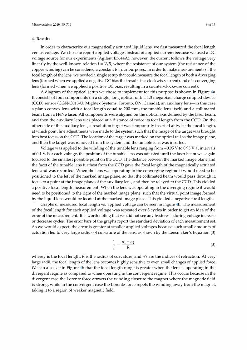
A diagram of the optical setup we chose to implement for this purpose is shown in Figure 4a.It consists of four components on a single, long optical rail: a 1.3 megapixel charge coupled device(CCD) sensor (CGN-C013-U, Mightex Systems, Toronto, ON, Canada), an auxiliary lens—in this casea plano-convex lens with a focal length equal to 200 mm, the tunable lens itself, and a collimatedbeam from a HeNe laser. All components were aligned on the optical axis defined by the laser beam,and then the auxiliary lens was placed at a distance of twice its focal length from the CCD. On theother side of the auxiliary lens, a resolution target was temporarily inserted at twice the focal length,at which point fine adjustments were made to the system such that the image of the target was broughtinto best focus on the CCD. The location of the target was marked on the optical rail as the image plane,and then the target was removed from the system and the tunable lens was inserted.
Voltage was applied to the winding of the tunable lens ranging from −0.95 V to 0.95 V at intervalsof 0.1 V. For each voltage, the position of the tunable lens was adjusted until the laser beam was againfocused to the smallest possible point on the CCD. The distance between the marked image plane andthe facet of the tunable lens furthest from the CCD gave the focal length of the magnetically actuatedlens and was recorded. When the lens was operating in the converging regime it would need to bepositioned to the left of the marked image plane, so that the collimated beam would pass through it,focus to a point at the image plane of the auxiliary lens, and then be relayed to the CCD. This yieldeda positive focal length measurement. When the lens was operating in the diverging regime it wouldneed to be positioned to the right of the marked image plane, such that the virtual point image formedby the liquid lens would be located at the marked image place. This yielded a negative focal length.
Graphs of measured focal length vs. applied voltage can be seen in Figure 4b. The measurementof the focal length for each applied voltage was repeated over 3 cycles in order to get an idea of theerror of the measurement. It is worth noting that we did not see any hysteresis during voltage increaseor decrease cycles. The error bars of the graphs report the standard deviation of each measurement set.As we would expect, the error is greater at smaller applied voltages because such small amounts ofactuation led to very large radius of curvature of the lens, as shown by the Lensmaker’s Equation (3)
1f=
n1 − n2
R(3)
where f is the focal length, R is the radius of curvature, and n’s are the indices of refraction. At verylarge radii, the focal length of the lens becomes highly sensitive to even small changes of applied force.We can also see in Figure 4b that the focal length range is greater when the lens is operating in thedivergent regime as compared to when operating in the convergent regime. This occurs because in thedivergent case the Lorentz force attracts the winding closer to the magnet where the magnetic fieldis strong, while in the convergent case the Lorentz force repels the winding away from the magnet,taking it to a region of weaker magnetic field.
Micromachines 2019, 10, 714 7 of 13Micromachines 2019, 10, x 7 of 13
Figure 4. (a) A diagram of the experimental setup for measuring the focal length of the tunable lens. A collimated laser beam acts as an object at infinity and an auxiliary lens with a 200 mm focal length is placed at a distance of twice of that focal length from a charge coupled device (CCD) detector and both are fixed in place. Then the tunable lens is allowed to slide along an optical rail and is adjusted until the light focuses to a point. The distance between the lens and the virtual object is the focal length. (b) The graph of lens focal length vs. applied voltage, with error bars showing standard deviation of the measurement under cycling. When negative voltages are applied the winding is attracted to the magnet and a concave lens (corresponding to a negative focal length) is formed. When positive voltages are applied, the direction of current flow is reversed, meaning the winding is repelled by the magnet and a convex (positive focal length) lens is formed.
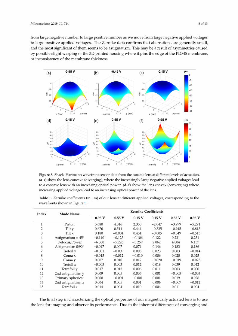
The next measurement we conducted was to measure the shape of the wavefront produced by our tunable lens (Figure 5). This was done using a Shack–Hartmann wavefront sensor (SHWS) equipped with a HeNe laser with a wavelength of 632 nm. Our SHWS (WFS150C, Thorlabs Inc., Newton, NJ, USA) setup allowed us to measure the shape of the central 4.75 mm region of our 15 mm diameter lens. At zero volts applied and no current through the wire, we would expect the wavefront to be essentially flat. As we began to apply voltage, we observed an increasing curvature to the wavefront shape. The z-axis of the wavefront sensor pointed towards the sensor, so that when the impinging wavefront was diverging (concave lens) the shape of the plotted wavefront was mounded, with peak values in the center region. When we changed the direction of the current, the wavefront became converging (convex lens) and the shape of the plotted waveform was cupped, with peak values at the outer region. This data can also be fitted with Zernike polynomials in order to describe the aberrations of the lens; the results are shown in Table 1. The defocus/power term in the table is
Figure 4. (a) A diagram of the experimental setup for measuring the focal length of the tunable lens.A collimated laser beam acts as an object at infinity and an auxiliary lens with a 200 mm focal length isplaced at a distance of twice of that focal length from a charge coupled device (CCD) detector and bothare fixed in place. Then the tunable lens is allowed to slide along an optical rail and is adjusted untilthe light focuses to a point. The distance between the lens and the virtual object is the focal length.(b) The graph of lens focal length vs. applied voltage, with error bars showing standard deviationof the measurement under cycling. When negative voltages are applied the winding is attracted tothe magnet and a concave lens (corresponding to a negative focal length) is formed. When positivevoltages are applied, the direction of current flow is reversed, meaning the winding is repelled by themagnet and a convex (positive focal length) lens is formed.
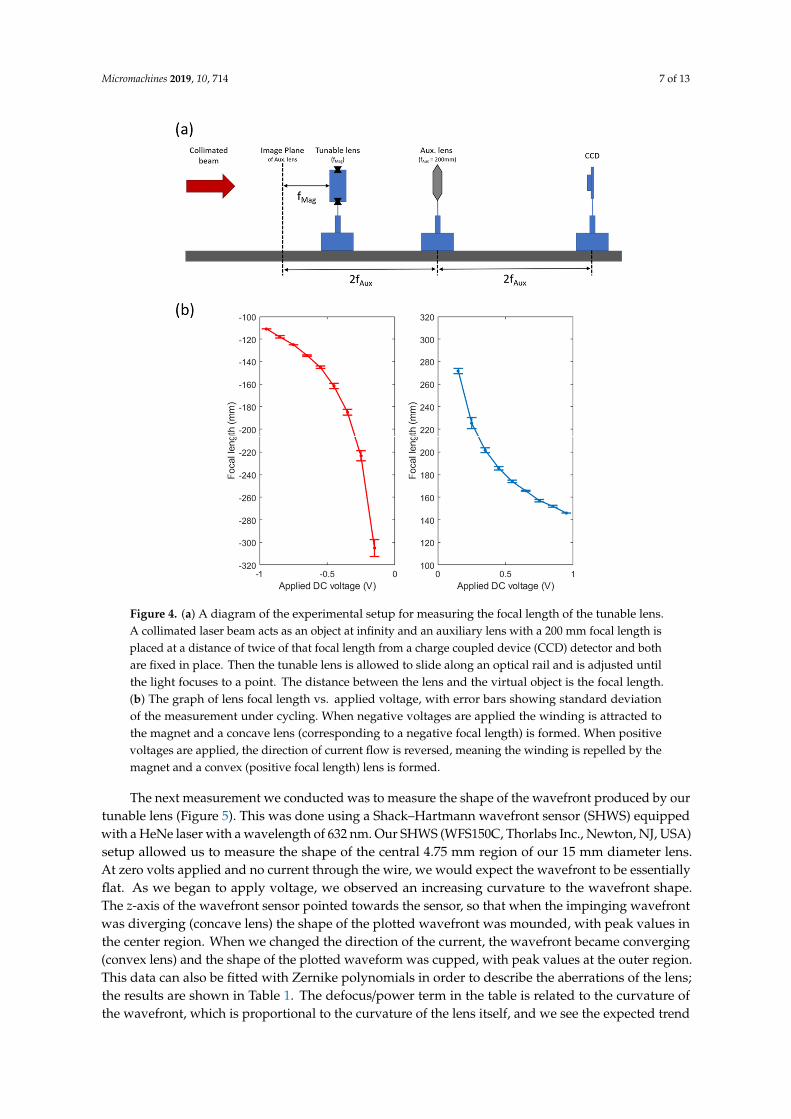
The next measurement we conducted was to measure the shape of the wavefront produced by ourtunable lens (Figure 5). This was done using a Shack–Hartmann wavefront sensor (SHWS) equippedwith a HeNe laser with a wavelength of 632 nm. Our SHWS (WFS150C, Thorlabs Inc., Newton, NJ, USA)setup allowed us to measure the shape of the central 4.75 mm region of our 15 mm diameter lens.At zero volts applied and no current through the wire, we would expect the wavefront to be essentiallyflat. As we began to apply voltage, we observed an increasing curvature to the wavefront shape.The z-axis of the wavefront sensor pointed towards the sensor, so that when the impinging wavefrontwas diverging (concave lens) the shape of the plotted wavefront was mounded, with peak values inthe center region. When we changed the direction of the current, the wavefront became converging(convex lens) and the shape of the plotted waveform was cupped, with peak values at the outer region.This data can also be fitted with Zernike polynomials in order to describe the aberrations of the lens;the results are shown in Table 1. The defocus/power term in the table is related to the curvature ofthe wavefront, which is proportional to the curvature of the lens itself, and we see the expected trend
Micromachines 2019, 10, 714 8 of 13
from large negative number to large positive number as we move from large negative applied voltagesto large positive applied voltages. The Zernike data confirms that aberrations are generally small,and the most significant of them seems to be astigmatism. This may be a result of asymmetries causedby possible slight warping of the 3D printed housing where it pins the edge of the PDMS membrane,or inconsistency of the membrane thickness.
Micromachines 2019, 10, x 8 of 13
related to the curvature of the wavefront, which is proportional to the curvature of the lens itself, and we see the expected trend from large negative number to large positive number as we move from large negative applied voltages to large positive applied voltages. The Zernike data confirms that aberrations are generally small, and the most significant of them seems to be astigmatism. This may be a result of asymmetries caused by possible slight warping of the 3D printed housing where it pins the edge of the PDMS membrane, or inconsistency of the membrane thickness.
Figure 5. Shack–Hartmann wavefront sensor data from the tunable lens at different levels of actuation. (a–c) show the lens concave (diverging), where the increasingly large negative applied voltages lead to a concave lens with an increasing optical power. (d–f) show the lens convex (converging) where increasing applied voltages lead to an increasing optical power of the lens.
Table 1. Zernike coefficients (in μm) of our lens at different applied voltages, corresponding to the wavefronts shown in Figure 5.
Index Mode Name Zernike Coefficients
−0.95 V −0.55 V −0.15 V 0.15 V 0.55 V 0.95 V 1 Piston 5.680 4.816 2.350 −2.047 −3.979 −5.291 2 Tilt y 0.676 0.511 0.444 −0.325 −0.945 −0.813 3 Tilt x 0.180 −0.004 0.454 −0.005 −0.349 −0.513 4 Astigmatism ± 45° −0.140 −0.123 −0.106 0.122 0.221 0.251 5 Defocus/Power −6.380 −5.226 −3.259 2.062 4.804 6.137 6 Astigmatism 0/90° −0.047 0.007 0.074 0.146 0.183 0.186 7 Trefoil y −0.001 −0.009 0.008 0.023 0.003 −0.014 8 Coma x −0.015 −0.012 −0.010 0.006 0.020 0.025 9 Coma y 0.007 0.010 0.012 −0.020 −0.019 −0.025
10 Trefoil x −0.005 0.003 0.012 0.018 0.039 0.042 11 Tetrafoil y 0.017 0.013 0.006 0.011 0.003 0.000 12 2nd astigmatism y 0.009 0.005 0.005 0.001 −0.005 −0.003 13 Primary spherical 0.000 −0.001 −0.001 0.001 0.019 0.026 14 2nd astigmatism x 0.004 0.005 0.001 0.006 −0.007 −0.012 15 Tetrafoil x 0.014 0.004 0.010 0.004 0.011 0.004
The final step in characterizing the optical properties of our magnetically actuated lens is to use the lens for imaging and observe its performance. Due to the inherent differences of converging and diverging lenses, two different setups were required to capture the performance of our tunable lens
Figure 5. Shack–Hartmann wavefront sensor data from the tunable lens at different levels of actuation.(a–c) show the lens concave (diverging), where the increasingly large negative applied voltages leadto a concave lens with an increasing optical power. (d–f) show the lens convex (converging) whereincreasing applied voltages lead to an increasing optical power of the lens.
Table 1. Zernike coefficients (in µm) of our lens at different applied voltages, corresponding to thewavefronts shown in Figure 5.
Index Mode NameZernike Coefficients
−0.95 V −0.55 V −0.15 V 0.15 V 0.55 V 0.95 V
1 Piston 5.680 4.816 2.350 −2.047 −3.979 −5.2912 Tilt y 0.676 0.511 0.444 −0.325 −0.945 −0.8133 Tilt x 0.180 −0.004 0.454 −0.005 −0.349 −0.5134 Astigmatism ± 45◦ −0.140 −0.123 −0.106 0.122 0.221 0.2515 Defocus/Power −6.380 −5.226 −3.259 2.062 4.804 6.1376 Astigmatism 0/90◦ −0.047 0.007 0.074 0.146 0.183 0.1867 Trefoil y −0.001 −0.009 0.008 0.023 0.003 −0.0148 Coma x −0.015 −0.012 −0.010 0.006 0.020 0.0259 Coma y 0.007 0.010 0.012 −0.020 −0.019 −0.025
10 Trefoil x −0.005 0.003 0.012 0.018 0.039 0.04211 Tetrafoil y 0.017 0.013 0.006 0.011 0.003 0.00012 2nd astigmatism y 0.009 0.005 0.005 0.001 −0.005 −0.00313 Primary spherical 0.000 −0.001 −0.001 0.001 0.019 0.02614 2nd astigmatism x 0.004 0.005 0.001 0.006 −0.007 −0.01215 Tetrafoil x 0.014 0.004 0.010 0.004 0.011 0.004
The final step in characterizing the optical properties of our magnetically actuated lens is to usethe lens for imaging and observe its performance. Due to the inherent differences of converging and
Micromachines 2019, 10, 714 9 of 13
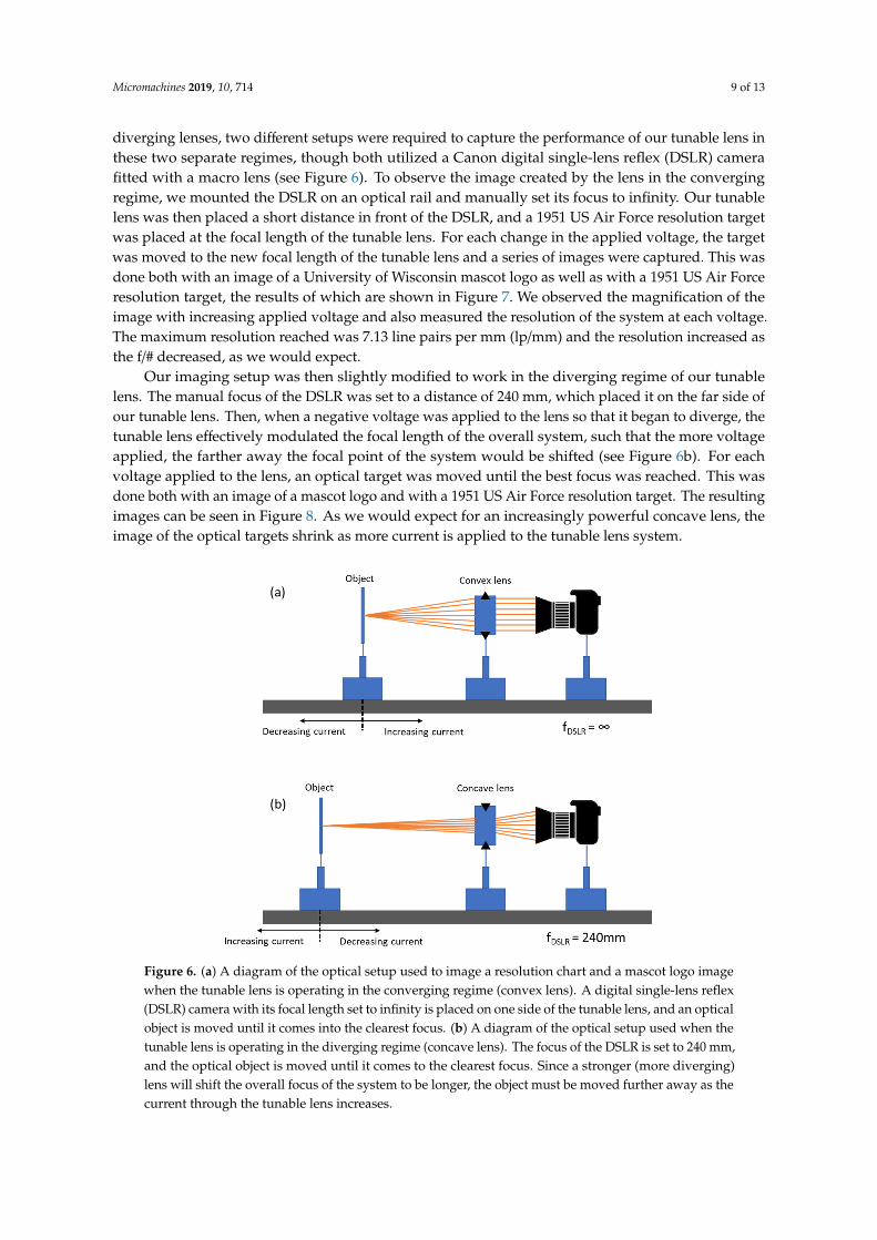
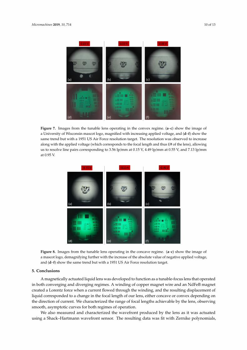
diverging lenses, two different setups were required to capture the performance of our tunable lens inthese two separate regimes, though both utilized a Canon digital single-lens reflex (DSLR) camerafitted with a macro lens (see Figure 6). To observe the image created by the lens in the convergingregime, we mounted the DSLR on an optical rail and manually set its focus to infinity. Our tunablelens was then placed a short distance in front of the DSLR, and a 1951 US Air Force resolution targetwas placed at the focal length of the tunable lens. For each change in the applied voltage, the targetwas moved to the new focal length of the tunable lens and a series of images were captured. This wasdone both with an image of a University of Wisconsin mascot logo as well as with a 1951 US Air Forceresolution target, the results of which are shown in Figure 7. We observed the magnification of theimage with increasing applied voltage and also measured the resolution of the system at each voltage.The maximum resolution reached was 7.13 line pairs per mm (lp/mm) and the resolution increased asthe f/# decreased, as we would expect.
Our imaging setup was then slightly modified to work in the diverging regime of our tunablelens. The manual focus of the DSLR was set to a distance of 240 mm, which placed it on the far side ofour tunable lens. Then, when a negative voltage was applied to the lens so that it began to diverge, thetunable lens effectively modulated the focal length of the overall system, such that the more voltageapplied, the farther away the focal point of the system would be shifted (see Figure 6b). For eachvoltage applied to the lens, an optical target was moved until the best focus was reached. This wasdone both with an image of a mascot logo and with a 1951 US Air Force resolution target. The resultingimages can be seen in Figure 8. As we would expect for an increasingly powerful concave lens, theimage of the optical targets shrink as more current is applied to the tunable lens system.
Micromachines 2019, 10, x 9 of 13
in these two separate regimes, though both utilized a Canon digital single-lens reflex (DSLR) camera fitted with a macro lens (see Figure 6). To observe the image created by the lens in the converging regime, we mounted the DSLR on an optical rail and manually set its focus to infinity. Our tunable lens was then placed a short distance in front of the DSLR, and a 1951 US Air Force resolution target was placed at the focal length of the tunable lens. For each change in the applied voltage, the target was moved to the new focal length of the tunable lens and a series of images were captured. This was done both with an image of a University of Wisconsin mascot logo as well as with a 1951 US Air Force resolution target, the results of which are shown in Figure 7. We observed the magnification of the image with increasing applied voltage and also measured the resolution of the system at each voltage. The maximum resolution reached was 7.13 line pairs per mm (lp/mm) and the resolution increased as the f/# decreased, as we would expect.
Our imaging setup was then slightly modified to work in the diverging regime of our tunable lens. The manual focus of the DSLR was set to a distance of 240 mm, which placed it on the far side of our tunable lens. Then, when a negative voltage was applied to the lens so that it began to diverge, the tunable lens effectively modulated the focal length of the overall system, such that the more voltage applied, the farther away the focal point of the system would be shifted (see Figure 6b). For each voltage applied to the lens, an optical target was moved until the best focus was reached. This was done both with an image of a mascot logo and with a 1951 US Air Force resolution target. The resulting images can be seen in Figure 8. As we would expect for an increasingly powerful concave lens, the image of the optical targets shrink as more current is applied to the tunable lens system.
Figure 6. (a) A diagram of the optical setup used to image a resolution chart and a mascot logo image when the tunable lens is operating in the converging regime (convex lens). A digital single-lens reflex (DSLR) camera with its focal length set to infinity is placed on one side of the tunable lens, and an optical object is moved until it comes into the clearest focus. (b) A diagram of the optical setup used when the tunable lens is operating in the diverging regime (concave lens). The focus of the DSLR is set to 240 mm, and the optical object is moved until it comes to the clearest focus. Since a stronger (more diverging) lens will shift the overall focus of the system to be longer, the object must be moved further away as the current through the tunable lens increases.
Figure 6. (a) A diagram of the optical setup used to image a resolution chart and a mascot logo imagewhen the tunable lens is operating in the converging regime (convex lens). A digital single-lens reflex(DSLR) camera with its focal length set to infinity is placed on one side of the tunable lens, and an opticalobject is moved until it comes into the clearest focus. (b) A diagram of the optical setup used when thetunable lens is operating in the diverging regime (concave lens). The focus of the DSLR is set to 240 mm,and the optical object is moved until it comes to the clearest focus. Since a stronger (more diverging)lens will shift the overall focus of the system to be longer, the object must be moved further away as thecurrent through the tunable lens increases.
Micromachines 2019, 10, 714 10 of 13
Micromachines 2019, 10, x 10 of 13
Figure 7. Images from the tunable lens operating in the convex regime. (a–c) show the image of a University of Wisconsin mascot logo, magnified with increasing applied voltage, and (d–f) show the same trend but with a 1951 US Air Force resolution target. The resolution was observed to increase along with the applied voltage (which corresponds to the focal length and thus f/# of the lens), allowing us to resolve line pairs corresponding to 3.56 lp/mm at 0.15 V, 4.49 lp/mm at 0.55 V, and 7.13 lp/mm at 0.95 V.
Figure 8. Images from the tunable lens operating in the concave regime. (a–c) show the image of a mascot logo, demagnifying further with the increase of the absolute value of negative applied voltage, and (d–f) show the same trend but with a 1951 US Air Force resolution target.
5. Conclusion
A magnetically actuated liquid lens was developed to function as a tunable-focus lens that operated in both converging and diverging regimes. A winding of copper magnet wire and an NdFeB magnet created a Lorentz force when a current flowed through the winding, and the resulting displacement of liquid corresponded to a change in the focal length of our lens, either concave or convex depending on the direction of current. We characterized the range of focal lengths achievable by the lens, observing smooth, asymptotic curves for both regimes of operation.
We also measured and characterized the wavefront produced by the lens as it was actuated using a Shack–Hartmann wavefront sensor. The resulting data was fit with Zernike polynomials, the coefficients of which were also reported. We observed very low spherical aberration, and the most significant contributor to aberrations was observed to be astigmatism, which may be from defects in the lens housing, or defects introduced during the fabrication process. Overall, aberrations were small, indicating a good lens quality. Finally, we demonstrated the imaging capability of the lens in
Figure 7. Images from the tunable lens operating in the convex regime. (a–c) show the image ofa University of Wisconsin mascot logo, magnified with increasing applied voltage, and (d–f) show thesame trend but with a 1951 US Air Force resolution target. The resolution was observed to increasealong with the applied voltage (which corresponds to the focal length and thus f/# of the lens), allowingus to resolve line pairs corresponding to 3.56 lp/mm at 0.15 V, 4.49 lp/mm at 0.55 V, and 7.13 lp/mmat 0.95 V.
Micromachines 2019, 10, x 10 of 13
Figure 7. Images from the tunable lens operating in the convex regime. (a–c) show the image of a University of Wisconsin mascot logo, magnified with increasing applied voltage, and (d–f) show the same trend but with a 1951 US Air Force resolution target. The resolution was observed to increase along with the applied voltage (which corresponds to the focal length and thus f/# of the lens), allowing us to resolve line pairs corresponding to 3.56 lp/mm at 0.15 V, 4.49 lp/mm at 0.55 V, and 7.13 lp/mm at 0.95 V.
Figure 8. Images from the tunable lens operating in the concave regime. (a–c) show the image of a mascot logo, demagnifying further with the increase of the absolute value of negative applied voltage, and (d–f) show the same trend but with a 1951 US Air Force resolution target.
5. Conclusion
A magnetically actuated liquid lens was developed to function as a tunable-focus lens that operated in both converging and diverging regimes. A winding of copper magnet wire and an NdFeB magnet created a Lorentz force when a current flowed through the winding, and the resulting displacement of liquid corresponded to a change in the focal length of our lens, either concave or convex depending on the direction of current. We characterized the range of focal lengths achievable by the lens, observing smooth, asymptotic curves for both regimes of operation.
We also measured and characterized the wavefront produced by the lens as it was actuated using a Shack–Hartmann wavefront sensor. The resulting data was fit with Zernike polynomials, the coefficients of which were also reported. We observed very low spherical aberration, and the most significant contributor to aberrations was observed to be astigmatism, which may be from defects in the lens housing, or defects introduced during the fabrication process. Overall, aberrations were small, indicating a good lens quality. Finally, we demonstrated the imaging capability of the lens in
Figure 8. Images from the tunable lens operating in the concave regime. (a–c) show the image ofa mascot logo, demagnifying further with the increase of the absolute value of negative applied voltage,and (d–f) show the same trend but with a 1951 US Air Force resolution target.
5. Conclusions
A magnetically actuated liquid lens was developed to function as a tunable-focus lens that operatedin both converging and diverging regimes. A winding of copper magnet wire and an NdFeB magnetcreated a Lorentz force when a current flowed through the winding, and the resulting displacement ofliquid corresponded to a change in the focal length of our lens, either concave or convex depending onthe direction of current. We characterized the range of focal lengths achievable by the lens, observingsmooth, asymptotic curves for both regimes of operation.
We also measured and characterized the wavefront produced by the lens as it was actuatedusing a Shack–Hartmann wavefront sensor. The resulting data was fit with Zernike polynomials,
Micromachines 2019, 10, 714 11 of 13
the coefficients of which were also reported. We observed very low spherical aberration, and the mostsignificant contributor to aberrations was observed to be astigmatism, which may be from defects inthe lens housing, or defects introduced during the fabrication process. Overall, aberrations were small,indicating a good lens quality. Finally, we demonstrated the imaging capability of the lens in bothconcave and convex regimes, utilizing a DSLR camera with the lens, observed the focal length tuning,and measured the resolution of the lens, which was found to be as high as 7.13 lp/mm.
After demonstrating the proof of concept, we now aim to reduce the size of the device to makeit more practical for miniaturized imaging systems. Further, relatively thick PDMS used in thisdevice, although mechanically robust, will require more pressure to deform compared to thinnermembrane. Thus in future downsizing, we will use thinner PDMS membrane. From the standpoint ofactuators, we plan to use smaller permanent magnets. Further, we will employ a smaller winding witha higher number of turns to provide enough wire length needed to generate adequate force. With thesealterations, we believe that it is practical to downsize the current device to sub-20-mm diameter foroverall packaging.
Author Contributions: Conceptualization, A.O.A. and H.J.; Data curation, K.L.V.G. and A.O.A.; Formal analysis,K.L.V.G.; Funding acquisition, H.J.; Methodology, K.L.V.G., A.O.A., and H.J.; Supervision, H.J.; Writing—originaldraft, K.L.V.G.; Writing—review and editing, A.O.A. and H.J.
Funding: This work was supported by the National Institute of Biomedical Imaging and Bioengineering of theU.S. National Institutes of Health under award number R01EB019460 and the U.S. National Science Foundationunder the Cyber-Physical Systems program (Grant number: CNS-1329481). This research utilized NSF supportedshared facilities at the University of Wisconsin.
Conflicts of Interest: The authors declare no conflict of interest.
References
1. Jiang, H.; Zeng, X. Microlenses: Properties, Fabrication and Liquid Lenses; CRC Press: Boca Raton, FL, USA,2013; ISBN 9781439836699.
2. Sato, S. Liquid-crystal lens-cells with variable focal length. Jpn. J. Appl. Phys. 1979, 18, 1679–1684. [CrossRef]3. Ren, H.; Fan, Y.H.; Gauza, S.; Wu, S.T. Tunable-focus flat liquid crystal spherical lens. Appl. Phys. Lett. 2004,
84, 4789–4791. [CrossRef]4. Ye, M.; Wang, B.; Sato, S. Liquid-crystal lens with a focal length that is variable in a wide range. Appl. Opt.
2004, 43, 6407. [CrossRef] [PubMed]5. Merlo, S.; Crisa, E.; Ferrera, M.; Soldo, M. Experimental detection of piezo-tunable micro-lens performances
by spot optical measurements. In Proceedings of the 2019 20th International Conference on Solid-StateSensors, Actuators and Microsystems & Eurosensors XXXIII (Transducers & Eurosensors XXXIII), Berlin,Germany, 23–27 June 2019; pp. 1541–1544.
6. Beadie, G.; Sandrock, M.L.; Wiggins, M.J.; Lepkowicz, R.S.; Shirk, J.S.; Ponting, M.; Yang, Y.; Kazmierczak, T.;Hiltner, A.; Baer, E. Tunable polymer lens. Opt. Express 2008, 16, 11847. [CrossRef] [PubMed]
7. Merlo, S.; Crisà, E.; Giusti, D.; Ferrera, M.; Soldo, M. Characterization of tunable micro-lenses with a versatileoptical measuring system. Sensors 2018, 18, 4396. [CrossRef] [PubMed]
8. Van Grinsven, K.L.; Ousati Ashtiani, A.; Jiang, H. Flexible electrowetting-on-dielectric microlens array sheet.Micromachines 2019, 10, 464. [CrossRef]
9. Dong, L.; Agarwal, A.K.; Beebe, D.J.; Jiang, H. Adaptive liquid microlenses activated by stimuli-responsivehydrogels. Nature 2006, 442, 551–554. [CrossRef]
10. Ousati Ashtiani, A.; Jiang, H. Design and fabrication of an electrohydrodynamically actuated microlens withareal density modulated electrodes. J. Micromech. Microeng. 2016, 26, 015004. [CrossRef]
11. Lu, Y.S.S.; Tu, H.; Xu, Y.; Jiang, H. Tunable dielectric liquid lens on flexible substrate. Appl. Phys. Lett. 2013,103, 261113. [CrossRef]
12. Almoallem, Y.D.; Jiang, H. Double-sided design of electrodes driving tunable dielectrophoretic miniaturelens. J. Microelectromech. Syst. 2017, 26, 1122–1131. [CrossRef]
13. Ousati Ashtiani, A.; Jiang, H. Thermally actuated tunable liquid microlens with sub-second response time.Appl. Phys. Lett. 2013, 103, 10–12. [CrossRef]
Micromachines 2019, 10, 714 12 of 13
14. Zhu, D.; Lo, C.; Li, C.; Jiang, H. Hydrogel-based tunable-focus liquid microlens array with fast response time.J. Microelectromech. Syst. 2012, 21, 1146–1155. [CrossRef]
15. Werber, A.; Zappe, H. Tunable microfluidic microlenses. Appl. Opt. 2005, 44, 3238–3245. [CrossRef] [PubMed]16. Werber, A.; Zappe, H. Tunable pneumatic microoptics. J. Microelectromech. Syst. 2008, 17, 1218–1227. [CrossRef]17. Zhang, W.; Zappe, H.; Seifert, A. Wafer-scale fabricated thermo-pneumatically tunable microlenses.
Light Sci. Appl. 2014, 3, e145. [CrossRef]18. Lee, J.K.K.; Park, K.W.; Lim, G.G.B.; Kim, H.; Kong, S.H.H. Variable-focus liquid lens based on
a laterally-integrated thermopneumatic actuator. J. Opt. Soc. Korea 2012, 16, 22–28. [CrossRef]19. Chronis, N.; Liu, G.; Jeong, K.H.; Lee, L. Tunable liquid-filled microlens array integrated with microfluidic
network. Opt. Express 2003, 11, 2370. [CrossRef]20. Kuiper, S.; Hendriks, B.H.W.; Huijbregts, L.J.; Hirschberg, A.M.; Renders, C.A.; van As, M.A.J. Variable-focus
liquid lens for portable applications. In Proceedings of the Optical Science and Technology, the SPIE 49thAnnual Meeting, Denver, CO, USA, 14 October 2004.
21. Van Grinsven, K.L.; Ousati Ashtiani, A.; Jiang, H. Fabrication and actuation of an electrowetting dropletarray on a flexible substrate. Micromachines 2017, 8, 334. [CrossRef]
22. Hendriks, B.H.W.; Kuiper, S.; VANAs, M.A.J.; Renders, C.A.; Tukker, T.W. Electrowetting-based variable-focuslens for miniature systems. Opt. Rev. 2005, 12, 255–259. [CrossRef]
23. Berge, B.; Peseux, J. Variable focal lens controlled by an external voltage: An application of electrowetting.Eur. Phys. J. E 2000, 3, 159–163. [CrossRef]
24. Li, C.; Jiang, H. Electrowetting-driven variable-focus microlens on flexible surfaces. Appl. Phys. Lett. 2012,100, 231105. [CrossRef] [PubMed]
25. Yu, H.; Zhou, G.; Chau, F.S.; Sinha, S.K. Tunable electromagnetically actuated liquid-filled lens. Sens. ActuatorsA Phys. 2011, 167, 602–607. [CrossRef]
26. Lee, S.W.; Lee, S.S. Focal tunable liquid lens integrated with an electromagnetic actuator. Appl. Phys. Lett.2007, 90, 121129. [CrossRef]
27. Hasan, N.; Banerjee, A.; Kim, H.; Mastrangelo, C.H. Tunable-focus lens for adaptive eyeglasses. Opt. Express2017, 25, 1221. [CrossRef]
28. Schneider, F.; Draheim, J.; Müller, C.; Wallrabe, U. Optimization of an adaptive PDMS-membrane lens withan integrated actuator. Sens. Actuators A Phys. 2009, 154, 316–321. [CrossRef]
29. Farghaly, M.A.; Akram, M.N.; Halvorsen, E. Modeling framework for piezoelectrically actuated MEMStunable lenses. Opt. Express 2016, 24, 28889. [CrossRef]
30. Farghaly, M.A.; Hanke, U.; Akram, M.N.; Halvorsen, E. Trial functions for reduced-order models ofpiezoelectrically actuated microelectromechanical systems tunable lenses. Opt. Eng. 2018, 57, 1. [CrossRef]
31. Farghaly, M.A.; Akram, M.N.; Halvorsen, E. Optical performance of piezoelectrically actuated MEMS tunablelenses with various pupil geometries. Opt. Eng. 2017, 56, 035104. [CrossRef]
32. Wallrabe, U. Axicons et al.—Highly aspherical adaptive optical elements for the life sciences. In Proceedings ofthe 2015 Transducers—2015 18th International Conference on Solid-State Sensors, Actuators and Microsystems(TRANSDUCERS), Anchorage, AK, USA, 21–25 June 2015; pp. 251–256.
33. Pouydebasque, A.; Bridoux, C.; Jacquet, F.; Moreau, S.; Sage, E.; Saint-Patrice, D.; Bouvier, C.; Kopp, C.;Marchand, G.; Bolis, S.; et al. Varifocal liquid lenses with integrated actuator, high focusing power and lowoperating voltage fabricated on 200 mm wafers. Sens. Actuators A Phys. 2011, 172, 280–286. [CrossRef]
34. Cheng, C.C.; Chang, C.A.; Yeh, J.A. Variable focus dielectric liquid droplet lens. Opt. Express 2006, 14,4101–4106. [CrossRef]
35. Lee, J.K.; Park, K.W.; Choi, J.C.; Kim, H.R.; Kong, S.H. Design and fabrication of PMMA-micromachinedfluid lens based on electromagnetic actuation on PMMA-PDMS bonded membrane. J. Micromech. Microeng.2012, 22, 115028. [CrossRef]
36. Cheng, H.C.; Xu, S.; Liu, Y.; Levi, S.; Wu, S.T. Adaptive mechanical-wetting lens actuated by ferrofluids.Opt. Commun. 2011, 284, 2118–2121. [CrossRef]
37. Oh, S.H.; Rhee, K.; Chung, S.K. Electromagnetically driven liquid lens. Sens. Actuators A Phys. 2016, 240,153–159. [CrossRef]
Micromachines 2019, 10, 714 13 of 13
38. Liu, C.S.; Lin, P.D.; Lin, P.H.; Ke, S.S.; Chang, Y.H.; Horng, J. Bin Design and characterization of miniatureauto-focusing voice coil motor actuator for cell phone camera applications. IEEE Trans. Magn. 2009, 45,155–159. [CrossRef]
39. Kim, M.; Kim, H.; Gweon, D.G. Design and optimization of voice coil actuator for six degree of freedomactive vibration isolation system using Halbach magnet array. Rev. Sci. Instrum. 2012, 83, 105117. [CrossRef]
40. Liu, C.S.; Lin, P.D. Miniaturized auto-focusing VCM actuator with zero holding current. Opt. Express 2009,17, 9754–9763. [CrossRef]
© 2019 by the authors. Licensee MDPI, Basel, Switzerland. This article is an open accessarticle distributed under the terms and conditions of the Creative Commons Attribution(CC BY) license (http://creativecommons.org/licenses/by/4.0/).