Embed Size (px)
Citation preview
TSWITX-G4-EVM Wireless Charging Transmitter
www.semtech.com
WIRELESS CHARGING
User Guide
TSWITX-G4-EVM Wireless Charging Transmitter
for TS51223-based Receivers (Rev 1.00)

TSWITX-G4-EVM www.semtech.com 1 of 18 User Guide Rev 1.00
Introduction The Semtech TSWITX-G4-EVM is an evaluation platform for the test and experimentation of a wireless charging transmitter based on the Semtech TS80002 Wireless Power Transmitter Controller and TS51231 Transmitter Controller. This evaluation module, in conjunction with its compatible receiver, the TSWIRX-5V2-EVM or TSWIRX-LI-EVM, provides a complete system solution for low-power, wearable infrastructure power transmission.
Objectives The objective of this User Guide is to provide a fast, easy and thorough method to experiment with and evaluate the Semtech solutions for wireless charging systems. Sufficient information is provided to support the engineer in all aspects of adding wireless charging support to their products. Semtech offers a variety of solutions to meet the needs of a wide range of system developers. Developers are provided with all the information on how this EVM was built as a starting point for their own designs using the TS80002 and other Semtech components.
Table of Contents
Wireless Charging Concepts .................................................................................................... 2
Product Description ................................................................................................................. 3
Standard Use .......................................................................................................................... 4
Documentation ........................................................................................................................ 7 A. Block Diagram .............................................................................................................. 7 B. Schematic .................................................................................................................... 8 C. Board Layout .............................................................................................................. 11 D. Board Layers .............................................................................................................. 12 E. Programming ............................................................................................................. 13
FAQs ..................................................................................................................................... 16
Next Steps ............................................................................................................................. 17
TSWITX-G4-EVM www.semtech.com 2 of 18 User Guide Rev 1.00
Receiver
Transmitter
Control
ElectromagneticFlux
Controller Coil DriverPowerSupply
Supply Regulation RectifierEnd
Equipment
Pow
er
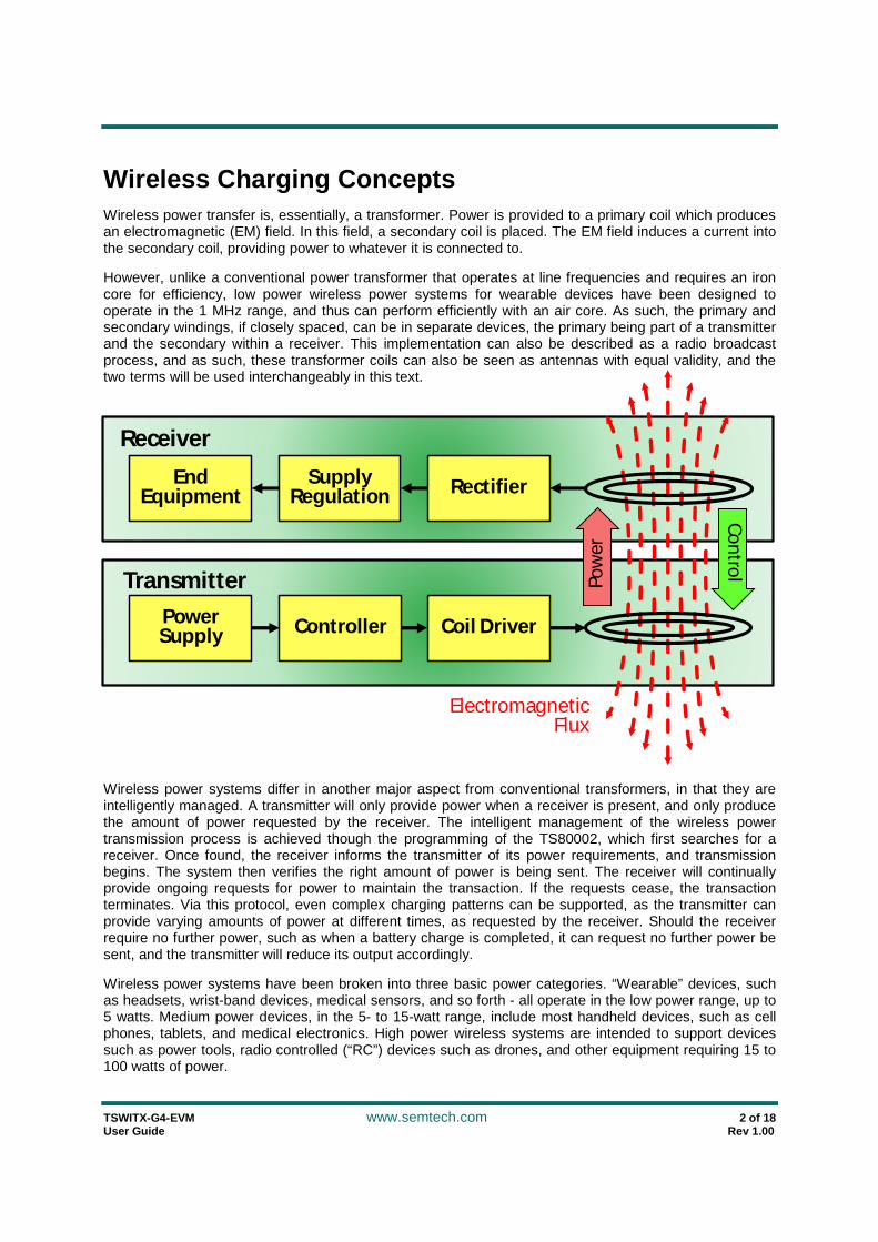
Wireless Charging Concepts Wireless power transfer is, essentially, a transformer. Power is provided to a primary coil which produces an electromagnetic (EM) field. In this field, a secondary coil is placed. The EM field induces a current into the secondary coil, providing power to whatever it is connected to.
However, unlike a conventional power transformer that operates at line frequencies and requires an iron core for efficiency, low power wireless power systems for wearable devices have been designed to operate in the 1 MHz range, and thus can perform efficiently with an air core. As such, the primary and secondary windings, if closely spaced, can be in separate devices, the primary being part of a transmitter and the secondary within a receiver. This implementation can also be described as a radio broadcast process, and as such, these transformer coils can also be seen as antennas with equal validity, and the two terms will be used interchangeably in this text.
Wireless power systems differ in another major aspect from conventional transformers, in that they are intelligently managed. A transmitter will only provide power when a receiver is present, and only produce the amount of power requested by the receiver. The intelligent management of the wireless power transmission process is achieved though the programming of the TS80002, which first searches for a receiver. Once found, the receiver informs the transmitter of its power requirements, and transmission begins. The system then verifies the right amount of power is being sent. The receiver will continually provide ongoing requests for power to maintain the transaction. If the requests cease, the transaction terminates. Via this protocol, even complex charging patterns can be supported, as the transmitter can provide varying amounts of power at different times, as requested by the receiver. Should the receiver require no further power, such as when a battery charge is completed, it can request no further power be sent, and the transmitter will reduce its output accordingly.
Wireless power systems have been broken into three basic power categories. “Wearable” devices, such as headsets, wrist-band devices, medical sensors, and so forth - all operate in the low power range, up to 5 watts. Medium power devices, in the 5- to 15-watt range, include most handheld devices, such as cell phones, tablets, and medical electronics. High power wireless systems are intended to support devices such as power tools, radio controlled (“RC”) devices such as drones, and other equipment requiring 15 to 100 watts of power.
TSWITX-G4-EVM www.semtech.com 3 of 18 User Guide Rev 1.00
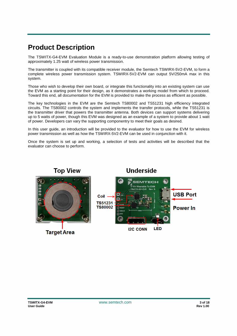
Product Description The TSWITX-G4-EVM Evaluation Module is a ready-to-use demonstration platform allowing testing of approximately 1.25 watt of wireless power transmission.
The transmitter is coupled with its compatible receiver module, the Semtech TSWIRX-5V2-EVM, to form a complete wireless power transmission system. TSWIRX-5V2-EVM can output 5V/250mA max in this system.
Those who wish to develop their own board, or integrate this functionality into an existing system can use the EVM as a starting point for their design, as it demonstrates a working model from which to proceed. Toward this end, all documentation for the EVM is provided to make the process as efficient as possible.
The key technologies in the EVM are the Semtech TS80002 and TS51231 high efficiency integrated circuits. The TS80002 controls the system and implements the transfer protocols, while the TS51231 is the transmitter driver that powers the transmitter antenna. Both devices can support systems delivering up to 5 watts of power, though this EVM was designed as an example of a system to provide about 1 watt of power. Developers can vary the supporting componentry to meet their goals as desired.
In this user guide, an introduction will be provided to the evaluator for how to use the EVM for wireless power transmission as well as how the TSWIRX-5V2-EVM can be used in conjunction with it.
Once the system is set up and working, a selection of tests and activities will be described that the evaluator can choose to perform.
TSWITX-G4-EVM www.semtech.com 4 of 18 User Guide Rev 1.00
Standard Use The TSWITX-G4-EVM is easy to set up and use. Connect a USB cable from any USB port capable of driving up to 2 watts (most PCs will suffice) to the USB port on the EVM. On application of power, the green LED should light, indicating the board is now active.
At this point, the EVM is ready to transmit power. A few times each second, the transmitter emits a ‘ping’ of energy in search of a compliant receiver in range.
When in range, the receiver is powered by the ping sufficiently to be able to announce its presence to the transmitter, and a transaction begins. The transmitter provides a small amount of power to the newly discovered receiver, so it can tell the transmitter what its power requirements are.
At the completion of this handshake, the transmitter begins providing the requested power. During power transfer, the receiver continuously communicates with the transmitter, actively directing the process. In this way, it is assured that power is only sent when and how it is required by an available and desirous receiver – and in the way that is compatible with the requirements of the receiver. If required, a receiver can actively increase or decrease its power request, and the transmitter will act accordingly. As such, equipment with complex charging requirements can be precisely supported and only the desired amount of power is provided.
EVM Receiver Tests
A variety of tests can be performed with the use of the TSWIRX-5V2-EVM receiver module.
In order to use the TSWIRX-5V2-EVM as a target receiver, simply place the receiver over the target circle on the transmitter EVM module. There will be 5V output on RX output.
The optimal load to select would be a Programmable DC Electronic Load. A ‘load box’ can easily be set to draw a selected current or power at the turn of a knob, making them very flexible and easy to use in observing power supply operation in general. If a load box is not available, a power resistor decade box is nearly as convenient, as it can easily be set to any desired resistance to simulate a range of load conditions. If need be, a selection of resistors could be used as test loads, though without the ease of modification of the prior options. Be sure the test load is rated for at least the amount of power being tested. Finally, any device that uses a 1.25W power can be used as a test load should that be desired.
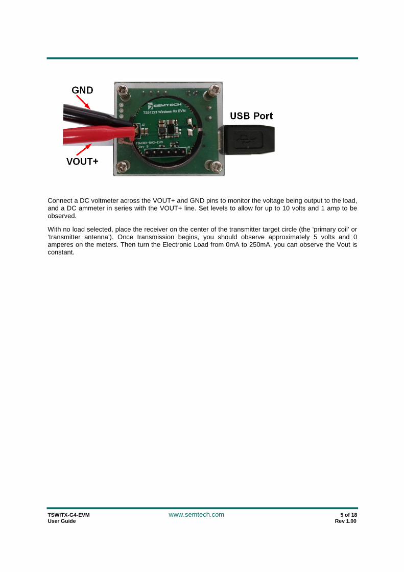
Whatever load is selected, wires must be run from the VOUT+ and GND pins of the receiver EVM to the selected test load, as per the following illustration. Once the load is added, the receiver EVM can be used to perform a variety of tests.
TSWITX-G4-EVM www.semtech.com 5 of 18 User Guide Rev 1.00
Connect a DC voltmeter across the VOUT+ and GND pins to monitor the voltage being output to the load, and a DC ammeter in series with the VOUT+ line. Set levels to allow for up to 10 volts and 1 amp to be observed.
With no load selected, place the receiver on the center of the transmitter target circle (the ‘primary coil’ or ‘transmitter antenna’). Once transmission begins, you should observe approximately 5 volts and 0 amperes on the meters. Then turn the Electronic Load from 0mA to 250mA, you can observe the Vout is constant.

TSWITX-G4-EVM www.semtech.com 6 of 18 User Guide Rev 1.00
Observe Coil Signals
The following information is not required in order to use the EVM, as what can be observed below is entirely managed by the Semtech TS80002 Wireless Controller. However, it allows the observer an opportunity to see how the receiver and transmitter actively manage the wireless power process.
If you wish to observe the intrinsic wireless process, place an oscilloscope probe on one antenna lead, with the probe ground run to the board ground (the outer casing of the USB port will suffice). Be sure the scope can handle signals up to 100 volts. While the EVM power supply is only 5 volts, the antenna is part of a resonant circuit where considerably higher voltages are developed.
To observe the search ping, apply power to the transmitter and remove the receiver from the target zone. The scope should display a ‘chirp’ of 0.5 to 1mSec in duration with an initial peak of 30 to 35 volts. The frequency within the envelope of the chirp is in the 1-1.15 MHz range.
Next, place the receiver on the transmitter target. With the scope set to 0.2 to 1 uSec and 2 to 10 volts per division, you should observe a ‘fuzzy sinewave’ signal that is a composite of the sinusoidal power signal with an additional component produced by the much lower frequency digital communication between the receiver and transmitter. Observing the signal in the 1 to 5 mSec range will allow the ability to see the digital signal riding on the power modulation more readily. Note as you vary the load and the location of the receiver on the target that the amplitude and frequency of the coil signal changes. The greater the load, the more signal is sent to transfer the power required by the load. Similarly, the less well coupled the receiver antenna is to the transmitter coil, the more power must be sent to compensate for the inefficient misalignment. You may note in excess of 50 volts peak-to-peak in the most demanding conditions.
Measure Efficiency
By measuring the power from the receiver’s VOUT+ and GND pins in comparison to the power entering the transmitter EVM, you can determine the efficiency of the power transfer through the system. The diagram below was obtained from the TSWITX-G4-EVM and TSWIRX-5V2-EVM. When measuring efficiency, be sure to remove the jumpers on the receiver and transmitter that enable the status LEDs, as these will affect the measurements.
0.00%
10.00%
20.00%
30.00%
40.00%
50.00%
60.00%
70.00%
0mA
10m
A20
mA
30m
A40
mA
50m
A
60m
A70
mA
80m
A90
mA
100m
A11
0mA
120m
A13
0mA
140m
A15
0mA
160m
A17
0mA
180m
A19
0mA
200m
A21
0mA
220m
A23
0mA
240m
A25
0mA
Efficiency vs Load

TSWITX-G4-EVM www.semtech.com 7 of 18 User Guide Rev 1.00
Documentation The following sections document the hardware design of the TSWITX-G4-EVM. This information can be used to better understand the functionality of the design, as well as assist in creating your own hardware solution based on this design
A. Block Diagram
The TSWITX-G4-EVM may be divided into a number of sub-blocks as show in the diagram below:
5 Volt Filter
Coil DriveTS51231
ControllerTS80002
FeedbackSignals
MatchingNetwork
Antenna: Transmit
5 Volt USB Input
Antenna:
Receive
5 Volt Filter - smooths the 5 volt input supply
Controller - based on the TS80002 Wireless Power Controller; manages all operations of the transmitter
Coil Driver - based on the TS51231 Transmitter Driver, powers the antenna based on inputs from controller
Antenna: Transmit - acts as the primary of an air-core transformer in conjunction with the receiver antenna
Feedback Signals - adapt the antenna and drive values for use as feedback input to the controller
TSWITX-G4-EVM www.semtech.com 8 of 18 User Guide Rev 1.00
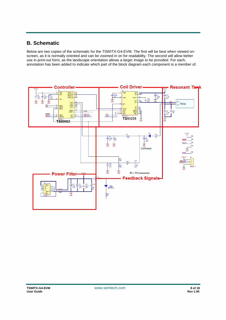
B. Schematic
Below are two copies of the schematic for the TSWITX-G4-EVM. The first will be best when viewed on-screen, as it is normally oriented and can be zoomed in on for readability. The second will allow better use in print-out form, as the landscape orientation allows a larger image to be provided. For each, annotation has been added to indicate which part of the block diagram each component is a member of.

TS
WIT
X-G
4-EV
M
w
ww
.semtech.com
9 of 18
User G
uide R
ev 1.00
NRST1
GPIO12
GPIO23
VSS4
LDO5VDD
6
ALERT7
SDA8SCL9
PWM1_L10
PWM2_L11
GPIO312
PWM1_H 13
PWM2_H14
DEBUG15
V_AC16
I_DC 17
GPIO418
VREF19
V_DC20
U1
TS80002
1uF6.3V
C5
GND
VCC5V
1uF6.3V
C3
GND
10nF10V
C4
GND
RESET
DEBUG
TP1
TP2
TP3
TP4
GND
VCC5V
RESETDEBUG
SCLSDA
SW11
VIN15
NC5
GND8
EN1
nFLT4
VDD7
HSON6
VIN 16
SCL3
SDA2
SW12
PGND13
PGND14
PAD 17
NC 9
BOOT10
U2
TS51231
VCC5V
100nF10V
C2
22uF6.3V
C1
GND
100nF10V
C7
GND
4.7nF50V
C6
GND
GNDGND GND
1nF100V
C9330K
R7
22KR8
D1
100nF10V
C8
Coil Feedback
1K
R9
4.7nF100V
C10
1K
R1110KR10
10KR121nF
10V
C11
GND GND RX -> TX Communication
100nF10V
C12
VCC5V
GND
SCLSDA
DONE
22uF6.3V
C17
GND
22nF10V
C184.7nF50V
C16
NCC19
22uF6.3V
C21
DONE TP5
AC1AC2
SMB_SCLSMB_SDA
VBUS1
D-2
D+3
GND5
x4
SHLD 6789
J1
5V IN
GND
VCC5V
TX CoilAC1
AC2
1KR20
1 2
J2
LED 0805
LED1GREEN
1234
J3
Header 4
VCC5V
GND
SMB_SDASMB_SCL
TSWITX-G4-EVM www.semtech.com 10 of 18 User Guide Rev 1.00
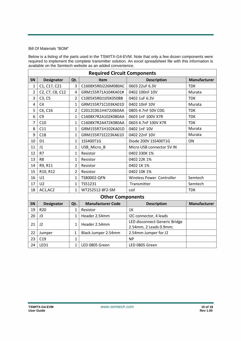
Bill Of Materials “BOM”
Below is a listing of the parts used in the TSWITX-G4-EVM. Note that only a few dozen components were required to implement the complete transmitter solution. An excel spreadsheet file with this information is available on the Semtech website as an added convenience.
Required Circuit Components
SN Designator Qt. Item Description Manufacturer
1 C1, C17, C21 3 C1608X5R0J226M080AC 0603 22uF 6.3V TDK
2 C2, C7, C8, C12 4 GRM155R71A104KA01# 0402 100nF 10V Murata
3 C3, C5 2 C1005X5R0J105K050BB 0402 1uF 6.3V TDK
4 C4 1 GRM155R71C103KA01D 0402 10nF 10V Murata
5 C6, C16 2 C2012C0G1H472J060AA 0805 4.7nF 50V C0G TDK
6 C9 1 C1608X7R2A102K080AA 0603 1nF 100V X7R TDK
7 C10 1 C1608X7R2A472K080AA 0603 4.7nF 100V X7R TDK
8 C11 1 GRM155R71H102KA01D 0402 1nF 10V Murata
9 C18 1 GRM155R71E223KA61D 0402 22nF 10V Murata
10 D1 1 1SS400T1G Diode 200V 1SS400T1G ON
11 J1 1 USB_Micro_B Micro USB connector 5V IN
12 R7 1 Resistor 0402 330K 1%
13 R8 1 Resistor 0402 22K 1%
14 R9, R11 2 Resistor 0402 1K 1%
15 R10, R12 2 Resistor 0402 10K 1%
16 U1 1 TS80002-QFN Wireless Power Controller Semtech
17 U2 1 TS51231 Transmitter Semtech
18 AC1,AC2 1 WT252512-8F2-SM coil TDK
Other Components
SN Designator Qt. Manufacturer Code Description Manufacturer
19 R20 1 Resistor 1K
20 J3 1 Header 2.54mm I2C connector, 4 leads
21 J2 1 Header 2.54mm LED disconnect Generic Bridge
2.54mm, 2 Leads 0.9mm;
22 Jumper 1 Black Jumper 2.54mm 2.54mm Jumper for J2
23 C19 1 NP
24 LED1 1 LED 0805 Green LED 0805 Green
TSWITX-G4-EVM www.semtech.com 11 of 18 User Guide Rev 1.00
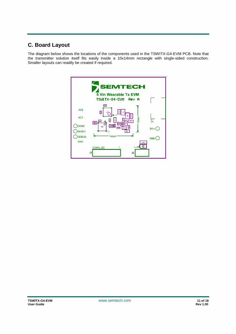
C. Board Layout
The diagram below shows the locations of the components used in the TSWITX-G4-EVM PCB. Note that the transmitter solution itself fits easily inside a 10x14mm rectangle with single-sided construction. Smaller layouts can readily be created if required.

TSWITX-G4-EVM www.semtech.com 12 of 18 User Guide Rev 1.00
D. Board Layers
The TSWITX-G4-EVM PCB is based on a four layer design as shown below. The ground plane in layer two is recommended to reduce noise and signal crosstalk. The EVM placed all components on the top of the board for easier evaluation of the system. End product versions of this design can be made significantly smaller by distributing components on both sides of the board. The Gerber files for this artwork can be downloaded from the Semtech web page.
Top Layer Ground Plane
Signal Layer Bottom Layer

TSWITX-G4-EVM www.semtech.com 13 of 18 User Guide Rev 1.00
E. Programming
TSWiTX-G4-EVM supports programming through I2C interface and a USB-I2C adapter.
Steps to Program TS80002 using Semtech Wireless Power GUI and Semtech USB-I2C adapter board:
1. Order a Semtech USB-I2C adapter board from Semtech. There is one adapter board in EVM kit.
2. Install the wireless power GUI. Please download from: http://www.semtech.com/apps/product.php?pn=TS80000
3. Find the 20 pin header J2 on USB-I2C adapter board; connect it to J3 on TSWITX-G4-EVM. J2 on adapter: Pin1 (VCC), Pin3 (SDA), Pin4 (SCL), Pin20 (GND) J3 on EVM: Pin1 (VCC), Pin2 (SDA), Pin3 (SCL), Pin4 (GND) There is an I2C cable in EVM kit to connect adapter and EVM: Red wire is VCC, Grey is SDA, Green is SCL, and Black is GND.
4. Short Debug pin to GND on your TS80002 board. There is a “DEBUG” test point on EVM, it is ease to
connect to “GND” next to it.
5. Connect your USB-I2C adapter board to your PC via an USB cable, it will be powered on.
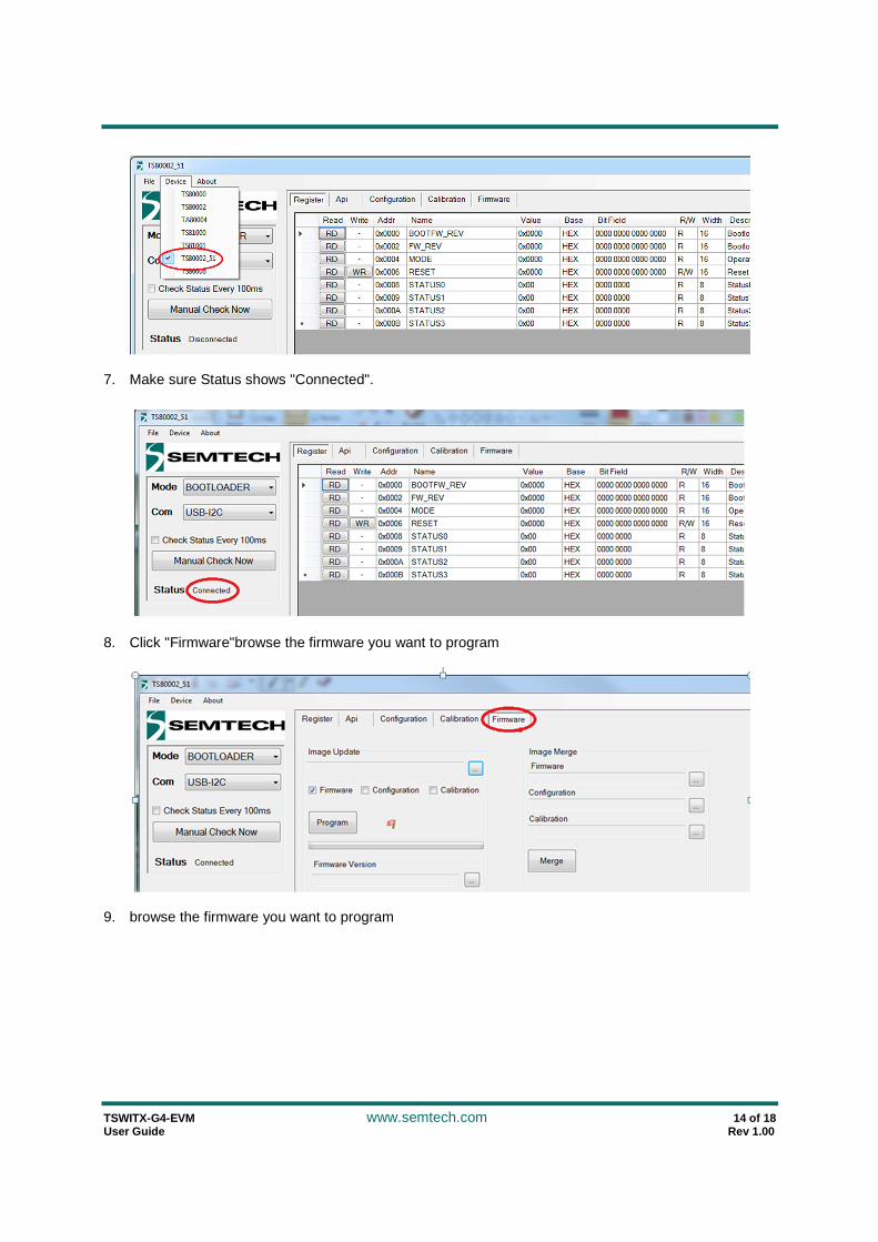
6. Run Semtech Wireless Power GUI and choose TS80002_51 from "Device” tab
TSWITX-G4-EVM www.semtech.com 14 of 18 User Guide Rev 1.00
7. Make sure Status shows "Connected".
8. Click "Firmware"browse the firmware you want to program
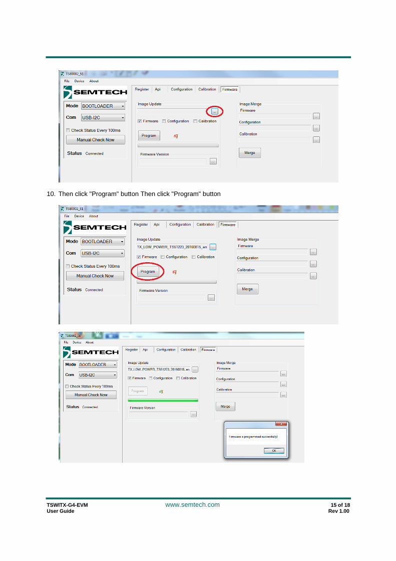
9. browse the firmware you want to program
TSWITX-G4-EVM www.semtech.com 15 of 18 User Guide Rev 1.00
10. Then click "Program" button Then click "Program" button

TSWITX-G4-EVM www.semtech.com 16 of 18 User Guide Rev 1.00
FAQs
Q: What output voltage is provided by the TSWITX-G4-EVM system?
A: Output voltage is receiver dependant. For the TSWIRX-5V2-EVM, the output is 5 volts.
Q: Is the TSWITX-G4-EVM compliant with Qi or another wireless transmission standard?
A: These low power wearable solutions are not based on existing standards in order to employ smaller coils and other optimizations that better suit the low power system environment.
Q: Does the EVM part number represent something in particular?
A: Yes. The part number is broken into a prefix, main body, and suffix, separated by dashes. The prefix is comprised of three two letter groupings that each help define the product represented. As such, the part number can be read as follows:
Prefix characters:
1+2 = Company : TS = Triune/Semtech
3+4 = Environment : DM = Dual Mode WI = Wearable Infrastructure
5+6 = Type : TX = Transmit RX = Receive
Mid-section = Device Voltage or Wattage
Suffix = Equipment type:
EVM = Evaluation Module
MOD = Production Module
Thus, the TSWITX-G4-EVM is a Wearable Infrastructure, Transmitter Evaluation Module provided by Semtech.
Q: Does the TSWITX-G4-EVM implement Foreign Object Detection (FOD)?
A: FOD detection is an important protection in higher power systems, but in low power wearable infrastructure systems there is no risk of overheating, rendering FOD management unnecessary.
Q: What if my questions weren’t answered here?
A: Go to the Semtech website as described on the next page. An updated FAQ for the TSWITX-G4-EVM is maintained there and may contain the answers you’re looking for. Your local Semtech FAE can also assist in answering your questions.

TSWITX-G4-EVM www.semtech.com 17 of 18 User Guide Rev 1.00
Next Steps
For more information on Wireless Power, go to the Semtech webpage at:
https://www.semtech.com/power-management/wireless-c harging-ics/
You may also scan the bar code to the right to go to the above web page:
There you can find the downloadable copies of the schematic, BOM, and board artwork, as well as additional information on how to obtain Semtech wireless power products, from the chip level all the way to complete board modules, as your needs require.
TSWITX-G4-EVM www.semtech.com 18 of 18 User Guide Rev 1.00
IMPORTANT NOTICE
Information relating to this product and the applic ation or design described herein is believed to be reliable, however such information is provided as a guide only and Se mtech assumes no liability for any errors in this d ocument, or for the application or design described herein. Semtech the latest relevant information before placing ord ers and should verify that such information is current and complet e. Semtech reserves the right to make changes to th e product or this document at any time without notice. Buyers sh ould obtain warrants performance of its products to the specifications applicable at the time of sale, and all sales are made in accordance with Semtech’s sta ndard terms and conditions of sale.
SEMTECH PRODUCTS ARE NOT DESIGNED, INTENDED, AUTHORIZED OR WARRANTED TO BE SUITABLE FOR USE IN LIFE-SUPPORT APPLICATIONS, DEVICES OR SYSTEMS, O R IN NUCLEAR APPLICATIONS IN WHICH THE FAILURE COULD BE REASONABLY EXPECTED TO RESULT IN P ERSONAL INJURY, LOSS OF LIFE OR SEVERE PROPERTY OR ENVIRONMENTAL DAMAGE. INCLUSION OF SEMT ECH PRODUCTS IN SUCH APPLICATIONS IS UNDERSTOOD TO BE UNDERTAKEN SOLELY AT THE CUSTOMER’ S OWN RISK. Should a customer purchase or use Semtech products for any such unauthorized applicat ion, the customer shall indemnify and hold Semtech and its officers, employees, subsidiaries, affiliates, and distributors harmless against all claims, costs dam ages and attorney fees which could arise.
The Semtech name and logo are registered trademarks of the Semtech Corporation. All other trademarks a nd trade names mentioned may be marks and names of Semtech o r their respective companies. Semtech reserves the right to make changes to, or discontinue any products descri bed in this document without further notice. Semtec h makes no warranty, representation or guarantee, express or i mplied, regarding the suitability of its products f or any particular purpose. All rights reserved.
© Semtech 2015
Contact Information
Semtech Corporation 200 Flynn Road, Camarillo, CA 93012
Phone: (805) 498-2111, Fax: (805) 498-3804 www.semtech.com