Embed Size (px)
Citation preview
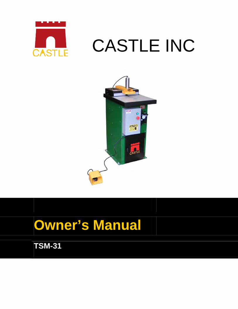
CASTLE INC
Owner’s Manual TSM-31

CASTLE, INC TSM-31 OWNERS MANUAL V1.1 Page 2 of 31
Table of Contents 1 INTRODUCTION ............................................................................................................................. 3
2 MACHINE SAFETY ......................................................................................................................... 4
2.1 SAFETY RULES .......................................................................................................................... 4
2.2 INVENTORY ................................................................................................................................ 5
2.3 MACHINE REQUIREMENTS .......................................................................................................... 6
3 SETTING UP YOUR TSM-31 ......................................................................................................... 7
4 OPERATING INSTRUCTIONS ....................................................................................................... 9
5 MACHINE ADJUSTMENTS .......................................................................................................... 10
5.1 WEB ADJUSTMENT ................................................................................................................... 10
5.2 POCKET DEPTH ADJUSTMENT................................................................................................... 11
5.3 PILOT DRILL DEPTH ADJUSTMENT ............................................................................................. 12
5.4 PILOT DRILL HEIGHT ADJUSTMENT ........................................................................................... 13
5.5 LEFT AND RIGHT PILOT DRILL ADJUSTMENT .............................................................................. 14
5.6 LEFT AND RIGHT ROUTER ADJUSTMENT .................................................................................... 15
5.7 ROUTER FEED SPEED .............................................................................................................. 16
5.8 DRILL FEED SPEED .................................................................................................................. 17
5.9 DRILL DELAY ADJUSTMENT....................................................................................................... 18
5.10 DRILL STOP SWITCH ................................................................................................................ 19
5.11 ROUTER STOP SWITCH ............................................................................................................ 20
6 DEFINITION AND DESCRIPTION OF PARTS ............................................................................ 22
7 SERVICE AND MAINTENANCE ................................................................................................... 28
7.1 GENERAL ................................................................................................................................28
7.2 MOTORS AND BITS ................................................................................................................... 29
7.3 SERIAL NUMBER LOG ............................................................................................................... 30
8 WARRANTY INFORMATION ....................................................................................................... 31

CASTLE, INC TSM-31 OWNERS MANUAL V1.1 Page 3 of 31
1 Introduction
Thank you for making the Castle TSM-31 the latest addition to your shop. Since 1985 our goal
has been to manufacture and develop machines that make cabinetmaking and casework easier,
faster and more profitable for the woodworker. This machine represents our commitment to your
productivity. Castle machines are made in Petaluma, California and are manufactured to the
highest standards using local vendors wherever possible.
This instruction manual is intended for use by anyone setting up or servicing this machine. It
should be kept available for immediate reference so that all operations can be performed with
maximum efficiency and safety.
Your TSM-31 will pocket any material you would normally rout. It is designed for material from 1
½” to ½”. Use of materials thinner than ½” is not recommended. Every TSM-31 machine is
factory adjusted and tested with sample material. If you should find a small amount of saw dust
in the bottom of your TSM-31, please don’t be alarmed.
Note: Do not attempt to perform maintenance or operate this machine until you have read and understand the information contained in this manual.
CASTLE, INC TSM-31 OWNERS MANUAL V1.1 Page 4 of 31
2 Machine Safety
This machine was carefully prepared for shipment at our factory. Upon receipt of the machine,
inspect for shipping damage. Report any damage IMMEDIATELY to the freight company, your
Castle dealer and to Castle, Inc. DO NOT attempt to operate the machine if you observe any
physical damage. Contact Castle, Inc. at 800-282-8338 for instructions.
2.1 Safety Rules
The Castle Model TSM-31 Pocket Machine was designed with operator safety as a priority,
which is why Castle highly recommends the following:
1. Always use a qualified electrician in hard wiring your machine to 1-phase electrical power.
2. Do not electrically wire machine until ready to operate.
3. Always wear eye protection when operating or servicing mechanical equipment.
4. Always wear hearing protection when the machine is in operation.
5. Always check for proper tooling tightness prior to use.
6. Do not at any time put hand under the clamp guard, in the path of router bit or drill bit.
7. Familiarize yourself with the clamping action, routing and drilling functions of the ma-
chine before electrically wiring the machine to any 1-phase electrical power supply.
8. Double check the tag on the electrical box of your machine to be sure it reads the proper 1-phase voltage that you are using with your machine.
9. NEVER ALLOW MACHINE TO GET WET OR BE USED IN A WET ENVIRONMENT.
CASTLE, INC TSM-31 OWNERS MANUAL V1.1 Page 5 of 31
2.2 Inventory
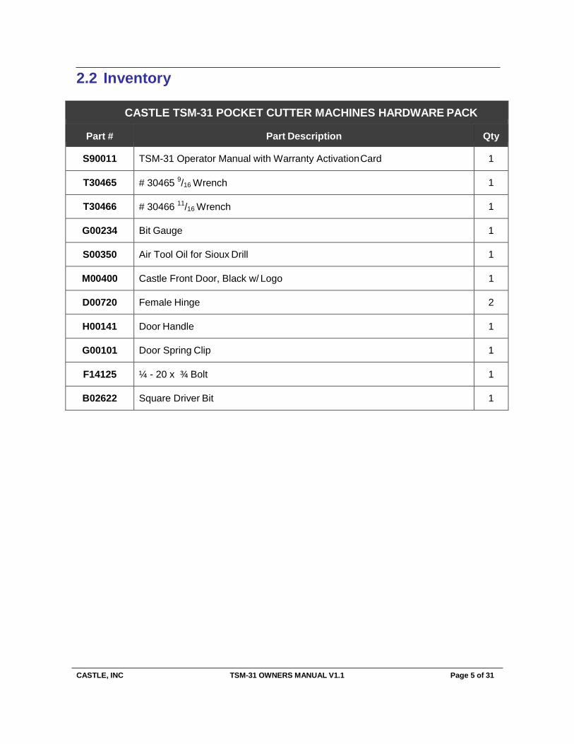
CASTLE TSM-31 POCKET CUTTER MACHINES HARDWARE PACK
Part # Part Description Qty
S90011 TSM-31 Operator Manual with Warranty Activation Card 1
T30465 # 30465 9/16 Wrench 1
T30466 # 30466 11/16 Wrench 1
G00234 Bit Gauge 1
S00350 Air Tool Oil for Sioux Drill 1
M00400 Castle Front Door, Black w/ Logo 1
D00720 Female Hinge 2
H00141 Door Handle 1
G00101 Door Spring Clip 1
F14125 ¼ - 20 x ¾ Bolt 1
B02622 Square Driver Bit 1

CASTLE, INC TSM-31 OWNERS MANUAL V1.1 Page 6 of 31
2.3 Machine Requirements
Electricity: 1-Phase 208VAC, 230VAC or 460VAC (see voltage tag on the machine or wiring
diagram inside the voltage box).
Shop Air Supply: 80 PSI minimum, 150 PSI maximum
Dust Collection: The TSM-31 relies on motor cooling from dust collection. A 4” dust collection
tube is located in the rear of the machine.
Caution: Always have a qualified electrician do any machine wiring.
CASTLE, INC TSM-31 OWNERS MANUAL V1.1 Page 7 of 31
3 Setting Up Your TSM-31
1. Remove the machine from the pallet, position and secure your machine in its chosen lo- cation.
Note: Holes in the base are for securing the machine to the floor. In some operations the machine should be elevated for better ergonomic operation but it still must be secured in place so that it cannot rock or tip.
2. Remove the brass elbow from the black urethane hose by pushing the floating ring to-
wards the elbow and pulling the hose at the same time.
3. Thread the elbow into the top of the Clamp Cylinder. It is pre-primed and self-sealing. Point it toward the back of the machine and firmly push the hose back into the fitting.
4. Supply compressed air to the Regulator/ Lubricator Assembly at the front of the machine.
The regulator is factory set at approximately 85 PSI. (Check the gauge to confirm this setting.) Castle suggests that a minimum of 3/8 inch air line should be used to operate this machine. Quick disconnects are not recommended as they generally restrict the air flow (volume).
5. Remove Lubricator bowl and fill to Maximum Oil Level line with proper oil (supplied), then replace full bowl.
6. Electrically hard wire to correct voltage as tagged on the machine. This is a 1-phase
machine and the voltage tag attached to the gray voltage box will show the voltage.
Caution: Use only a qualified electrician to hard wire your machine.
Note: The machine will not start if the air is off and/or the Case Top is in the lifted position.
7. Connect a dust collection system to the machine. Collection systems clear particles of
dust as well as venting heat away from your machine motor.
8. In the event that you are using your TSM-31 for face frames, we have provided adjust- able stops for faster, more efficient pocket cutting.
9. Check the rotation direction of the router before operation. The bit should turn counter
clockwise. To check direction, start machine by pressing the green Start Button on the
Caution: Inadequate air supply may cause the machine to malfunction.
Caution: Always use eye protection when operating power equipment.

CASTLE, INC TSM-31 OWNERS MANUAL V1.1 Page 8 of 31
gray electrical box at the front of the machine. Press red Stop Button and look into the slot where the bit comes up to make the pocket. As the machine slows to a stop, notice the direction.
Warning: Do not open the lid to check the direction as it will turn for several seconds after the
motor has been shut off.
If the bit turns in the wrong direction (clockwise) go to the Troubleshooting section of this
manual. Do not attempt to cut a pocket yet. First, read the entire manual before you
begin cutting pockets.
CASTLE, INC TSM-31 OWNERS MANUAL V1.1 Page 9 of 31
4 Operating Instructions
1. With the air on and the Case Top down, press the green Start Button. Note: the red Stop Button must be in the “out” position before the Start Button will activate your machine. If the red button is pushed in, simply turn the button ¼ turn counter clockwise to release.
2. Place stock to be pocketed under the yellow Clamp Guard.
3. To cut a pocket, push in the Safety Buttons under the Clamp Guard with the material to
be pocketed and depress the Foot Pedal to activate the machine.
4. The cycle start up must be achieved by both the Foot Pedal AND the Safety Buttons. The Foot Pedal does not have to be released to repeat the machine cycle but the Foot Pedal must be depressed to operate the machine.
5. The machine will extend the Hold-down Clamp, cut the pocket, drill the pilot hole, and
then release the Hold-down Clamp when the process cycle is complete.
6. Remove the stock and inspect the pocket. If the pocket and pilot hole look correct, you are ready to proceed with production.
7. A typical machine cycle will take from 1 ½ to 2 seconds to complete if the machine is
functioning properly.
8. If the machine fails to cycle properly, call Castle at (800) 282-8338.
Caution: Always use eye and hearing protection when operating machinery.
CASTLE, INC TSM-31 OWNERS MANUAL V1.1 Page 10 of 31
5 Machine Adjustments
Your TSM-31 comes factory-adjusted to handle typical pocket-hole needs. Some additional
adjustment may be necessary after you have satisfied the air and electrical requirements
explained above. Your pockets are adjusted at the factory for a 1 ½” length screw.
Note: For your safety, before making any adjustments please make sure that the red Stop Button is in the OFF position and both power and air are disconnected.
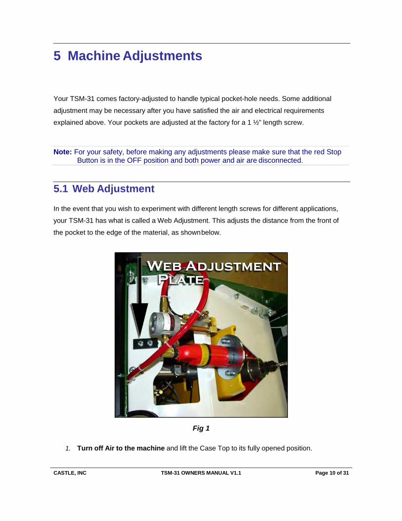
5.1 Web Adjustment
In the event that you wish to experiment with different length screws for different applications,
your TSM-31 has what is called a Web Adjustment. This adjusts the distance from the front of
the pocket to the edge of the material, as shown below.
Fig 1
1. Turn off Air to the machine and lift the Case Top to its fully opened position.
CASTLE, INC TSM-31 OWNERS MANUAL V1.1 Page 11 of 31
2. Locate the 7/8” x 2” plate mounted on the back of the white pallet, to the right of center, behind the air drill motor.
3. Use a 7/16” wrench to loosen both of the ¼” hex head cap screws on the 7/8” x 2” plate.
4. Once both bolts are loose the plate can move forward and backward. By moving the plate toward the rear of your machine, your pocket will adjust for a shorter distance from the edge of your material. Moving the plate toward the front of the machine will adjust for a longer distance from the edge of your material.
5. This is a trial and error method and should be moved only a small amount at a time.
6. After making each adjustment, snug down the ¼” hex head cap screws with your
7/16” wrench each time.
Be sure to close the Case Top and turn on air before trying to start your machine. The machine
will not start with the Case Top open or with the air off.
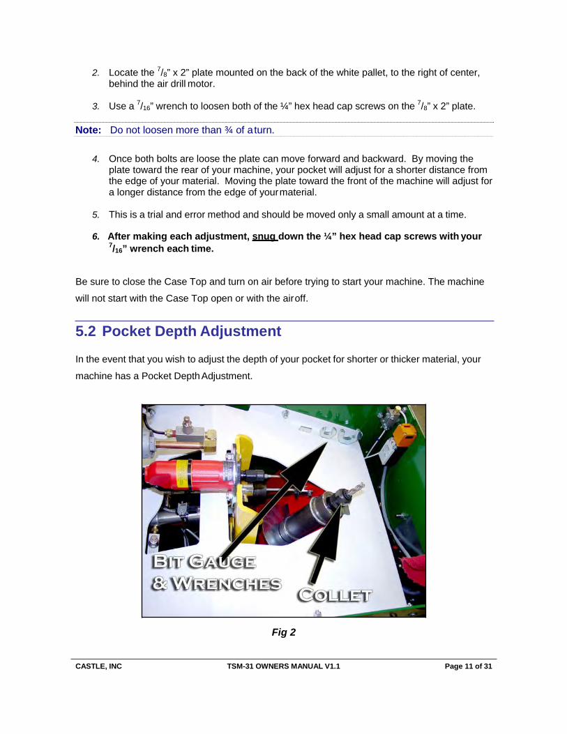
5.2 Pocket Depth Adjustment
In the event that you wish to adjust the depth of your pocket for shorter or thicker material, your
machine has a Pocket Depth Adjustment.
Fig 2
Note: Do not loosen more than ¾ of a turn.
CASTLE, INC TSM-31 OWNERS MANUAL V1.1 Page 12 of 31
1. Turn off Air and Electrical power to your machine and raise the Case Top to its fully open position.
2. With wrenches provided, loosen the collet and move the router bit up or down slightly in
the collet. Re-tighten the collet before testing.
3. An aluminum Bit Gauge has been provided so that you may record the depth that is most suitable for your purposes. When optimum height has been achieved, set the edge of gauge on top of the router collet and score a line at the top of the bit near the mark “R” for router bit.
4. Tighten the collet, replace the wrenches and Bit Gauge in the proper slots in the white
pallet; and close the Case Top carefully so as not to pinch your hand or fingers. The ma- chine will not start while the Case Top is open.
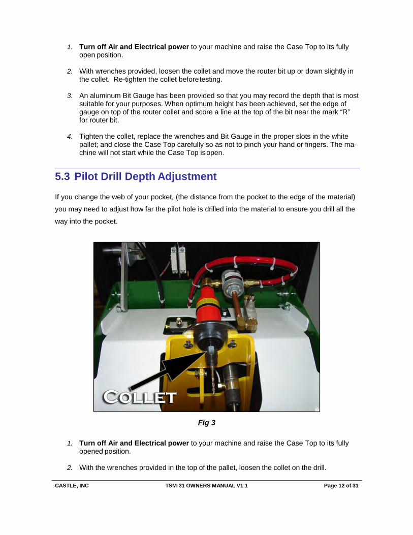
5.3 Pilot Drill Depth Adjustment
If you change the web of your pocket, (the distance from the pocket to the edge of the material)
you may need to adjust how far the pilot hole is drilled into the material to ensure you drill all the
way into the pocket.
Fig 3
1. Turn off Air and Electrical power to your machine and raise the Case Top to its fully opened position.
2. With the wrenches provided in the top of the pallet, loosen the collet on the drill.
CASTLE, INC TSM-31 OWNERS MANUAL V1.1 Page 13 of 31
3. After the collet has been loosened, move the drill bit in or out of the collet to adjust the depth of the pilot hole. Pull the bit out of the collet for a deeper pilot hole and push the drill bit in for a shallower pilot hole.
4. Once you have found the proper adjustment for your application, place the bottom of the
aluminum Bit Gauge against the top of the drill collet.
5. Use a scoring tool to mark a line of reference across the aluminum gauge.
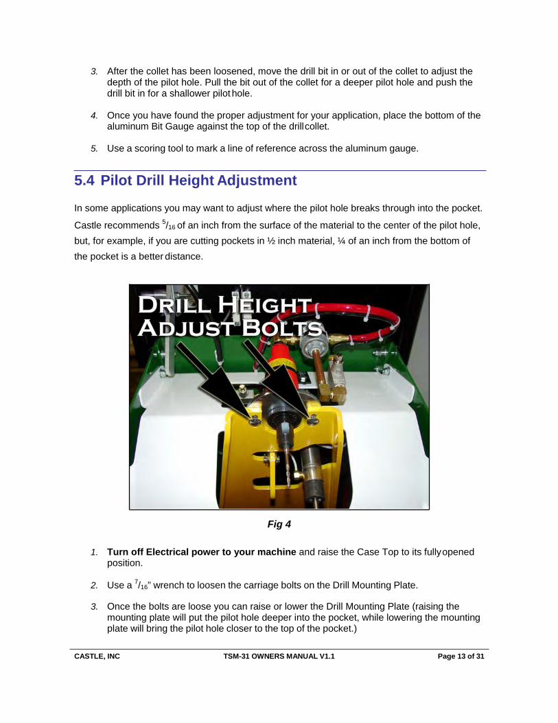
5.4 Pilot Drill Height Adjustment
In some applications you may want to adjust where the pilot hole breaks through into the pocket.
Castle recommends 5/16 of an inch from the surface of the material to the center of the pilot hole, but, for example, if you are cutting pockets in ½ inch material, ¼ of an inch from the bottom of the pocket is a better distance.
Fig 4
1. Turn off Electrical power to your machine and raise the Case Top to its fully opened position.
2. Use a 7/16” wrench to loosen the carriage bolts on the Drill Mounting Plate.
3. Once the bolts are loose you can raise or lower the Drill Mounting Plate (raising the mounting plate will put the pilot hole deeper into the pocket, while lowering the mounting plate will bring the pilot hole closer to the top of the pocket.)
CASTLE, INC TSM-31 OWNERS MANUAL V1.1 Page 14 of 31
4. Once you have moved the Drill Mounting Plate tighten the carriage bolts, close the Case Top and test to see if the pilot hole is set to the appropriate height for your particular ap- plication.
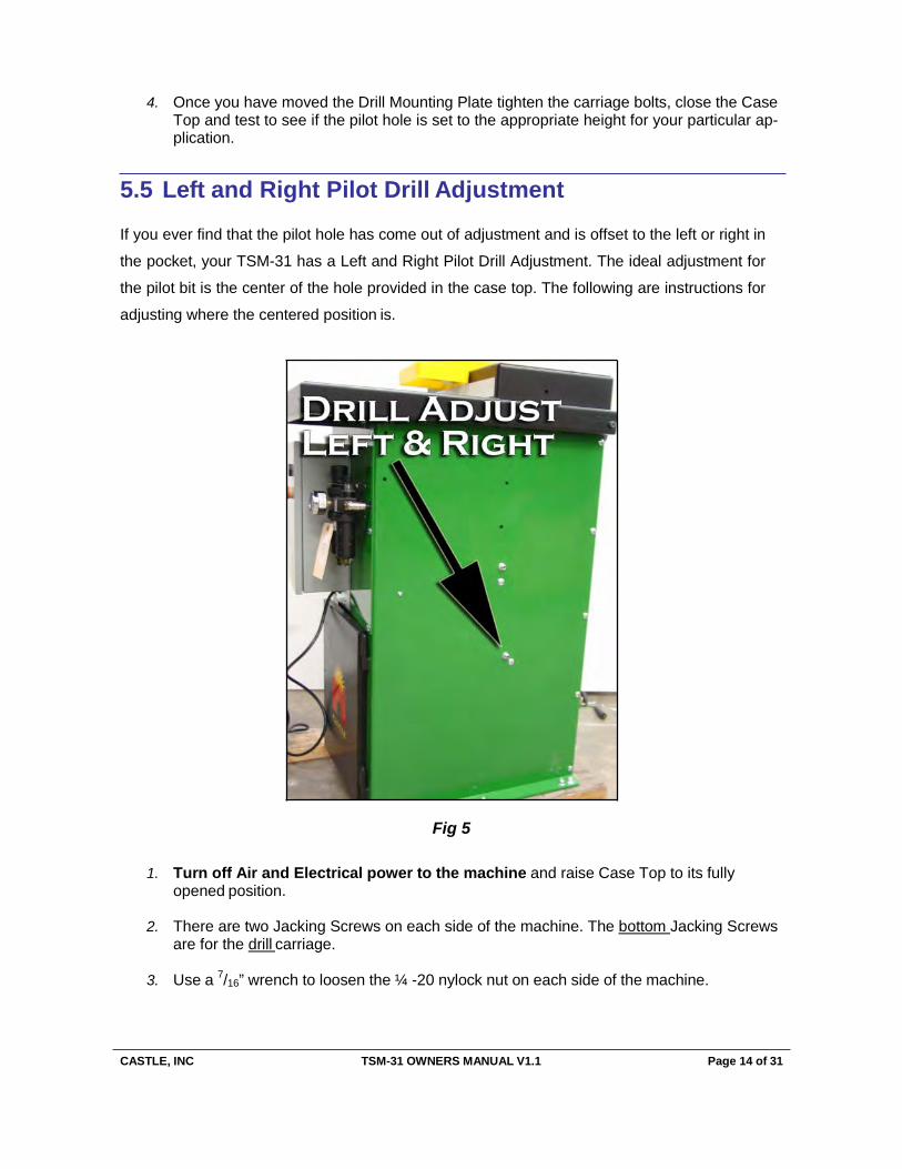
5.5 Left and Right Pilot Drill Adjustment
If you ever find that the pilot hole has come out of adjustment and is offset to the left or right in
the pocket, your TSM-31 has a Left and Right Pilot Drill Adjustment. The ideal adjustment for
the pilot bit is the center of the hole provided in the case top. The following are instructions for
adjusting where the centered position is.
Fig 5
1. Turn off Air and Electrical power to the machine and raise Case Top to its fully opened position.
2. There are two Jacking Screws on each side of the machine. The bottom Jacking Screws
are for the drill carriage.
3. Use a 7/16” wrench to loosen the ¼ -20 nylock nut on each side of the machine.
CASTLE, INC TSM-31 OWNERS MANUAL V1.1 Page 15 of 31
4. Once the nylock nuts are loose, use a 1/8” Allen wrench to move the carriage left or right. Loosen the left side and tighten the right to move the carriage to the left. Loosen the right side and tighten the left to move the carriage to the right.
5. Once you have adjusted the Jacking Screws, apply air and power to the machine and cut
a test pocket.
6. If the pilot hole is in the appropriate position for the particular application, use a 1/8” Allen wrench to secure each Jacking Screw while tightening the ¼-20 nylock nut with a 7/16” wrench on both sides of the machine.
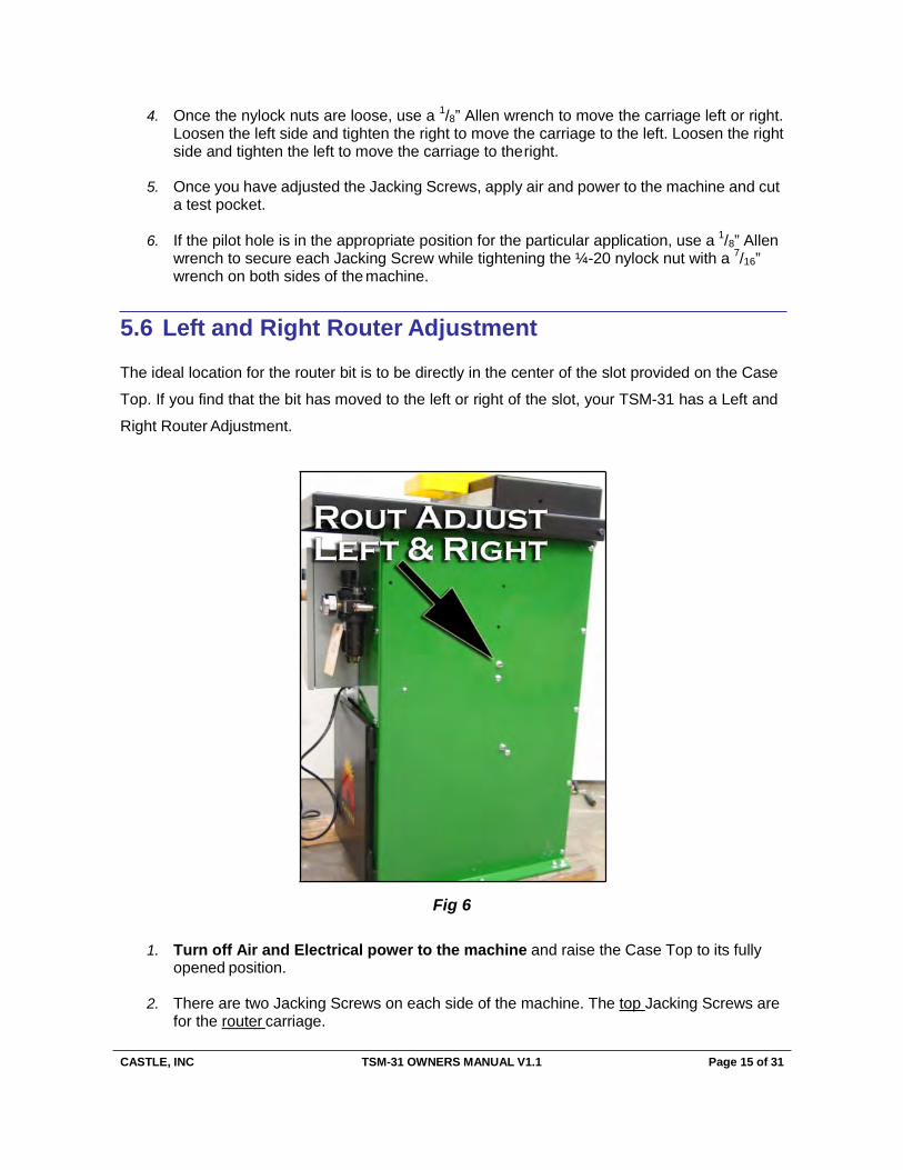
5.6 Left and Right Router Adjustment
The ideal location for the router bit is to be directly in the center of the slot provided on the Case
Top. If you find that the bit has moved to the left or right of the slot, your TSM-31 has a Left and
Right Router Adjustment.
Fig 6
1. Turn off Air and Electrical power to the machine and raise the Case Top to its fully opened position.
2. There are two Jacking Screws on each side of the machine. The top Jacking Screws are
for the router carriage.

CASTLE, INC TSM-31 OWNERS MANUAL V1.1 Page 16 of 31
3. Use a 7/16” wrench to loosen the ¼ -20 nylock nut on each side of the machine.
4. Once the nylock nuts are loose, use a 1/8” Allen wrench to move the carriage left and right. Loosen the left side and tighten the right to move the carriage to the left. Loosen the right side and tighten the left to move the carriage to the right.
5. Once you have adjusted the Jacking Screws, apply air and power to the machine and cut
a test pocket.
6. If the pilot hole is in the appropriate position for the particular application, use a 1/8” Allen wrench to secure each Jacking Screw while tightening the ¼-20 nylock nut with 7/16” wrench on both sides of the machine.
5.7 Router Feed Speed
Your TSM-31 is equipped with a Router Feed Speed Adjustment to allow you to cut pockets
faster or slower depending on the material you are cutting. For example, if you are cutting soft
wood, it may be better for your machine to cut faster to avoid having your bit spin in the material
too long. This can cause the bit to heat up and become dull. In applications where you are
cutting hard wood with your TSM-31, you may want to slow the speed at which your router cuts
a pocket. Feeding too fast into hard material can damage your tooling as well.
Fig 7
1. The adjustment for the Router Feed Speed is located on the front of the machine in the upper right hand corner below the case top.
CASTLE, INC TSM-31 OWNERS MANUAL V1.1 Page 17 of 31
2. Turn on the machine and push a scrap of test wood against the safety buttons.
3. Cut a pocket and note the speed of forward thrust during the rout part of the cycle.
4. Adjust the flow control knob counter-clockwise to increase the speed of the forward thrust and adjust it clockwise to slow the speed of the forward thrust.
5. Once the appropriate rout speed has been found, tighten the jam nut on the flow control to ensure that machine stays in adjustment.
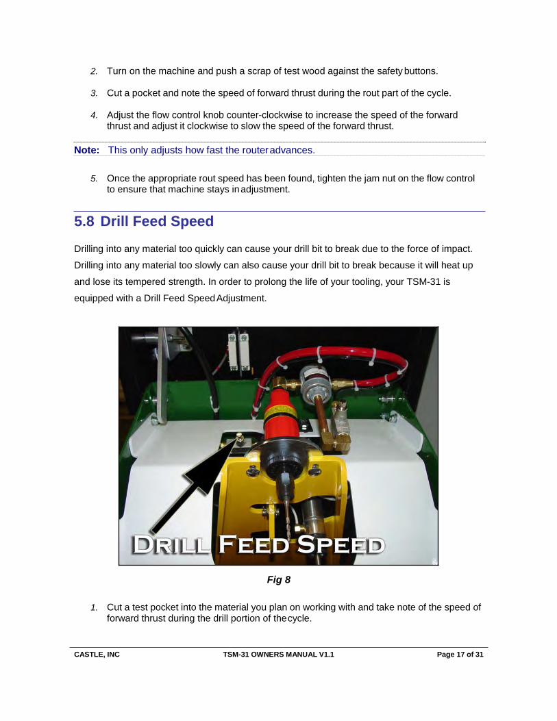
5.8 Drill Feed Speed
Drilling into any material too quickly can cause your drill bit to break due to the force of impact.
Drilling into any material too slowly can also cause your drill bit to break because it will heat up
and lose its tempered strength. In order to prolong the life of your tooling, your TSM-31 is
equipped with a Drill Feed Speed Adjustment.
Fig 8
1. Cut a test pocket into the material you plan on working with and take note of the speed of forward thrust during the drill portion of the cycle.
Note: This only adjusts how fast the router advances.
CASTLE, INC TSM-31 OWNERS MANUAL V1.1 Page 18 of 31
2. Turn off Air and Electrical power to the machine and lift the Case Top to its fully opened position.
3. The flow control for the Drill Feed Speed Adjustment is to the rear of the machine, just
left of center, and below the white safety pallet.
4. Once you have located the Drill Feed Speed knob, turn it counter-counterclockwise to in- crease the speed of the forward thrust and clockwise to decrease the speed of the for- ward thrust. NOTE: This only adjusts how fast the drill advances.
5. After the adjustment has been made close the Case Top and restore air and power to
the machine.
6. Cut a test pocket, then repeat this process if needed.
7. Once you have found the appropriate Drill Feed Speed for the particular application, tighten the jam nut on the Drill Feed Speed flow control to ensure your machine stays in adjustment.
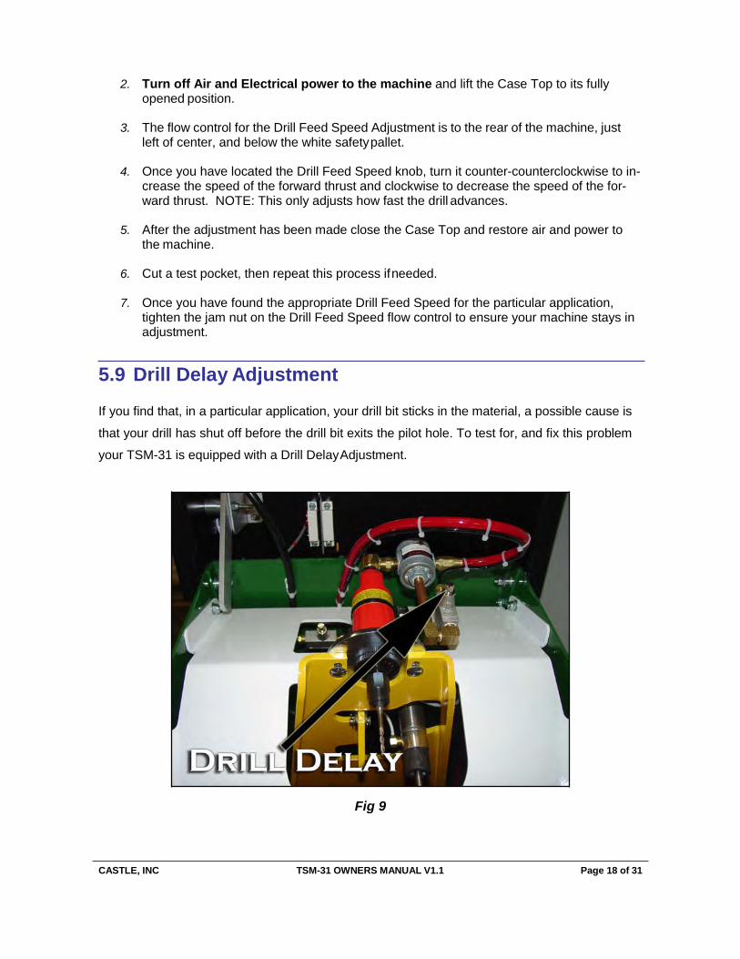
5.9 Drill Delay Adjustment
If you find that, in a particular application, your drill bit sticks in the material, a possible cause is
that your drill has shut off before the drill bit exits the pilot hole. To test for, and fix this problem
your TSM-31 is equipped with a Drill Delay Adjustment.
Fig 9
CASTLE, INC TSM-31 OWNERS MANUAL V1.1 Page 19 of 31
1. Turn off Electrical power to your machine and raise the Case Top to its fully opened position.
2. Locate the Drill Delay flow control mounted next to the drill.
3. To keep the drill spinning longer, loosen the jam nut on the flow control, then turn the
knob clockwise ½ turn. Please note that this ONLY controls how long the drill stays on during the cycle. The drill should NOT remain spinning indefinitely.
4. Close the Case Top, restore power, and cut a test pocket. Repeat this process if neces-
sary.
5. Once you have found the proper adjustment, tighten the jam nut on the flow control to ensure your machine stays in adjustment.
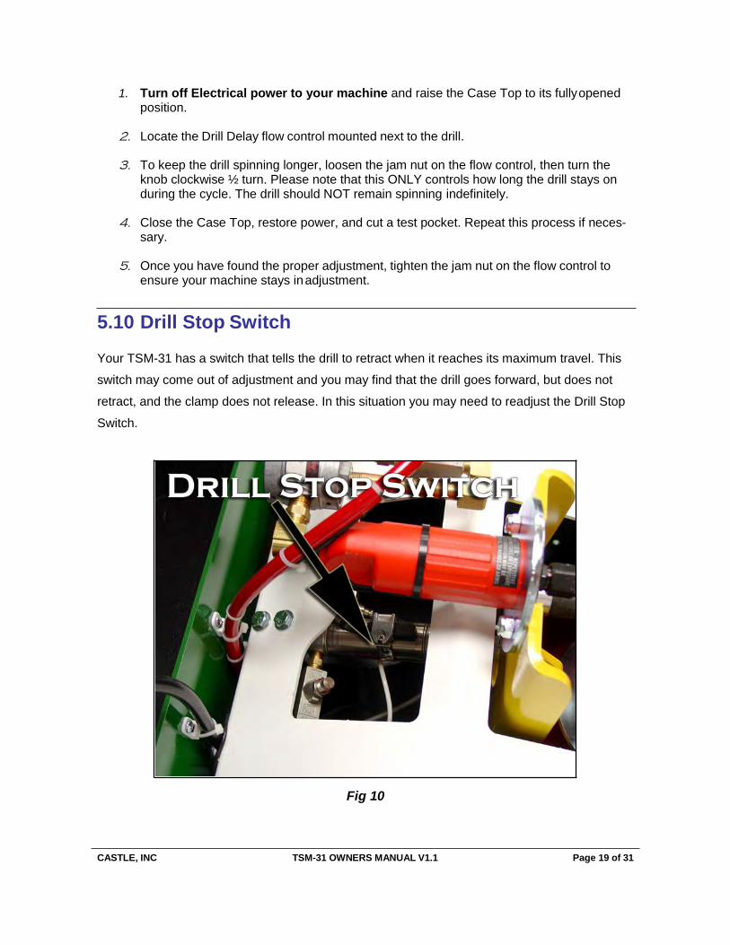
5.10 Drill Stop Switch
Your TSM-31 has a switch that tells the drill to retract when it reaches its maximum travel. This
switch may come out of adjustment and you may find that the drill goes forward, but does not
retract, and the clamp does not release. In this situation you may need to readjust the Drill Stop
Switch.
Fig 10
CASTLE, INC TSM-31 OWNERS MANUAL V1.1 Page 20 of 31
1. Turn off Air and Electrical power to the machine and raise the Case Top to its fully opened position.
2. Under the red drill, you will find two cylinders. The cylinder on the left is the cylinder
which drives the Drill Carriage.
3. On the Drill Carriage Cylinder there is a magnetic reed switch with a tensioning screw. Use a Phillips screw driver to loosen the screw so that the switch can move freely.
4. Open the door on the Control Box after you are sure that electrical power and air have
been shut off to the machine.
5. Use a continuity tester and touch it to pins 9 and 10 on the Control Board Terminal Strip. You might read a few kilo Ohms of resistance.
6. Once touching 9 and 10, pull the Drill Carriage forward until it is approximately 1/16 inch
away from the end of the stroke and hold in place.
7. Slide the Drill Stop Switch until you read NO RESISTANCE and tighten the tensioning screw.
5.11 Router Stop Switch
Much like the Drill Stop Switch, the Router Carriage also uses a magnetic reed switch to tell your
TSM-31 when it has reached the end of its stroke for the router part of the cycle. In the event
that this switch comes out of adjustment, your router will come up in the pocket and either return
before reaching the end of the stroke, or the router bit will not return at all after cutting the
pocket.
Note: Over tightening this screw may cause switch failure.
CASTLE, INC TSM-31 OWNERS MANUAL V1.1 Page 21 of 31
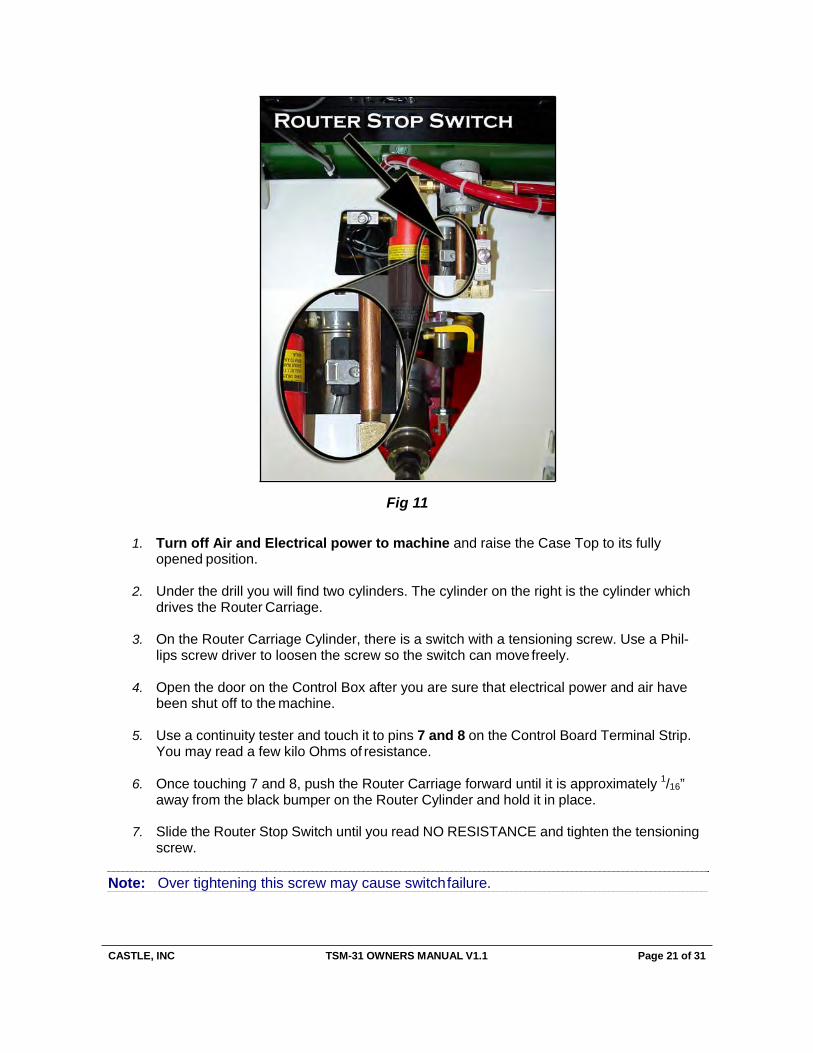
Fig 11
1. Turn off Air and Electrical power to machine and raise the Case Top to its fully opened position.
2. Under the drill you will find two cylinders. The cylinder on the right is the cylinder which
drives the Router Carriage.
3. On the Router Carriage Cylinder, there is a switch with a tensioning screw. Use a Phil- lips screw driver to loosen the screw so the switch can move freely.
4. Open the door on the Control Box after you are sure that electrical power and air have
been shut off to the machine.
5. Use a continuity tester and touch it to pins 7 and 8 on the Control Board Terminal Strip. You may read a few kilo Ohms of resistance.
6. Once touching 7 and 8, push the Router Carriage forward until it is approximately 1/16”
away from the black bumper on the Router Cylinder and hold it in place.
7. Slide the Router Stop Switch until you read NO RESISTANCE and tighten the tensioning screw.
Note: Over tightening this screw may cause switch failure.
CASTLE, INC TSM-31 OWNERS MANUAL V1.1 Page 22 of 31
ooucputas.teTardhpFeooencRekdtoehueSteptorepFeedrie:gdhtScpoerendervoaflvtehecomnatcrohlisnehobwelfoawsththeCascei TRrLo
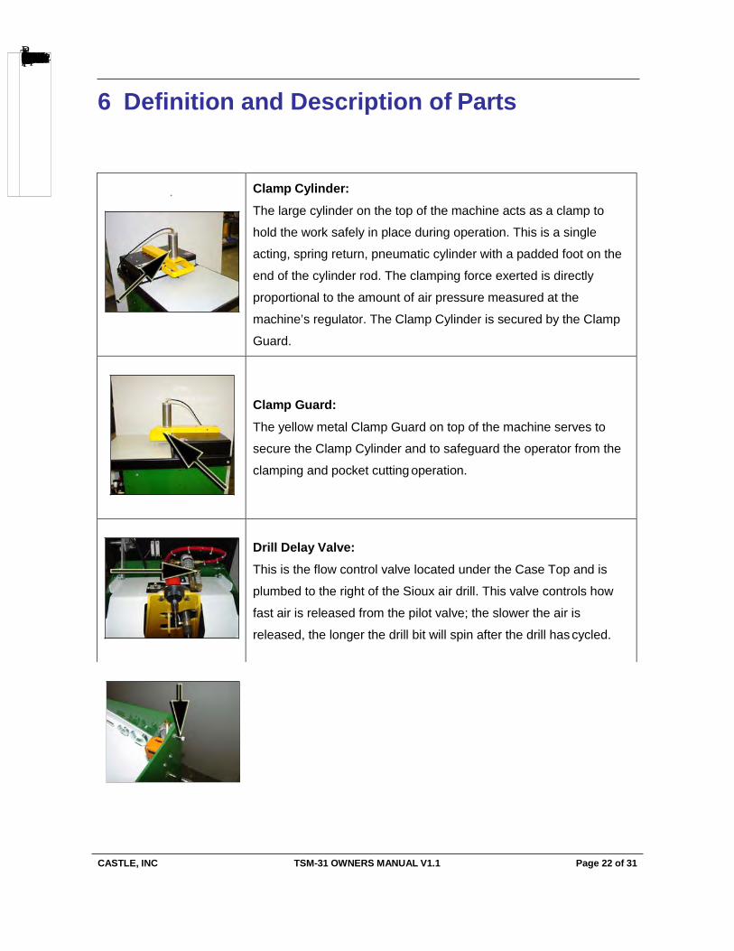
6 Definition and Description of Parts
+ Clamp Cylinder:
The large cylinder on the top of the machine acts as a clamp to
hold the work safely in place during operation. This is a single
acting, spring return, pneumatic cylinder with a padded foot on the
end of the cylinder rod. The clamping force exerted is directly
proportional to the amount of air pressure measured at the
machine’s regulator. The Clamp Cylinder is secured by the Clamp
Guard.
Clamp Guard:
The yellow metal Clamp Guard on top of the machine serves to
secure the Clamp Cylinder and to safeguard the operator from the
clamping and pocket cutting operation.
Drill Delay Valve: This is the flow control valve located under the Case Top and is
plumbed to the right of the Sioux air drill. This valve controls how
fast air is released from the pilot valve; the slower the air is
released, the longer the drill bit will spin after the drill has cycled.
CASTLE, INC TSM-31 OWNERS MANUAL V1.1 Page 23 of 31
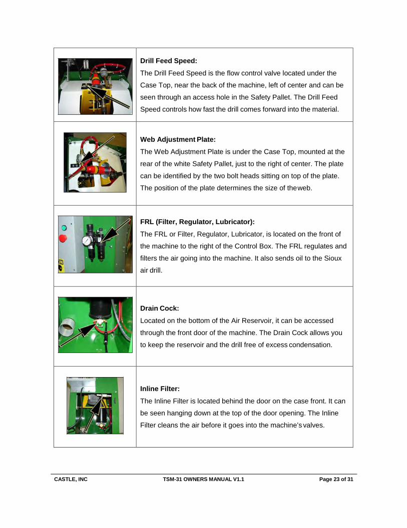
Drill Feed Speed:
The Drill Feed Speed is the flow control valve located under the
Case Top, near the back of the machine, left of center and can be
seen through an access hole in the Safety Pallet. The Drill Feed
Speed controls how fast the drill comes forward into the material.
Web Adjustment Plate: The Web Adjustment Plate is under the Case Top, mounted at the
rear of the white Safety Pallet, just to the right of center. The plate
can be identified by the two bolt heads sitting on top of the plate.
The position of the plate determines the size of the web.
FRL (Filter, Regulator, Lubricator):
The FRL or Filter, Regulator, Lubricator, is located on the front of
the machine to the right of the Control Box. The FRL regulates and
filters the air going into the machine. It also sends oil to the Sioux
air drill.
Drain Cock:
Located on the bottom of the Air Reservoir, it can be accessed
through the front door of the machine. The Drain Cock allows you
to keep the reservoir and the drill free of excess condensation.
Inline Filter:
The Inline Filter is located behind the door on the case front. It can
be seen hanging down at the top of the door opening. The Inline
Filter cleans the air before it goes into the machine’s valves.
CASTLE, INC TSM-31 OWNERS MANUAL V1.1 Page 24 of 31
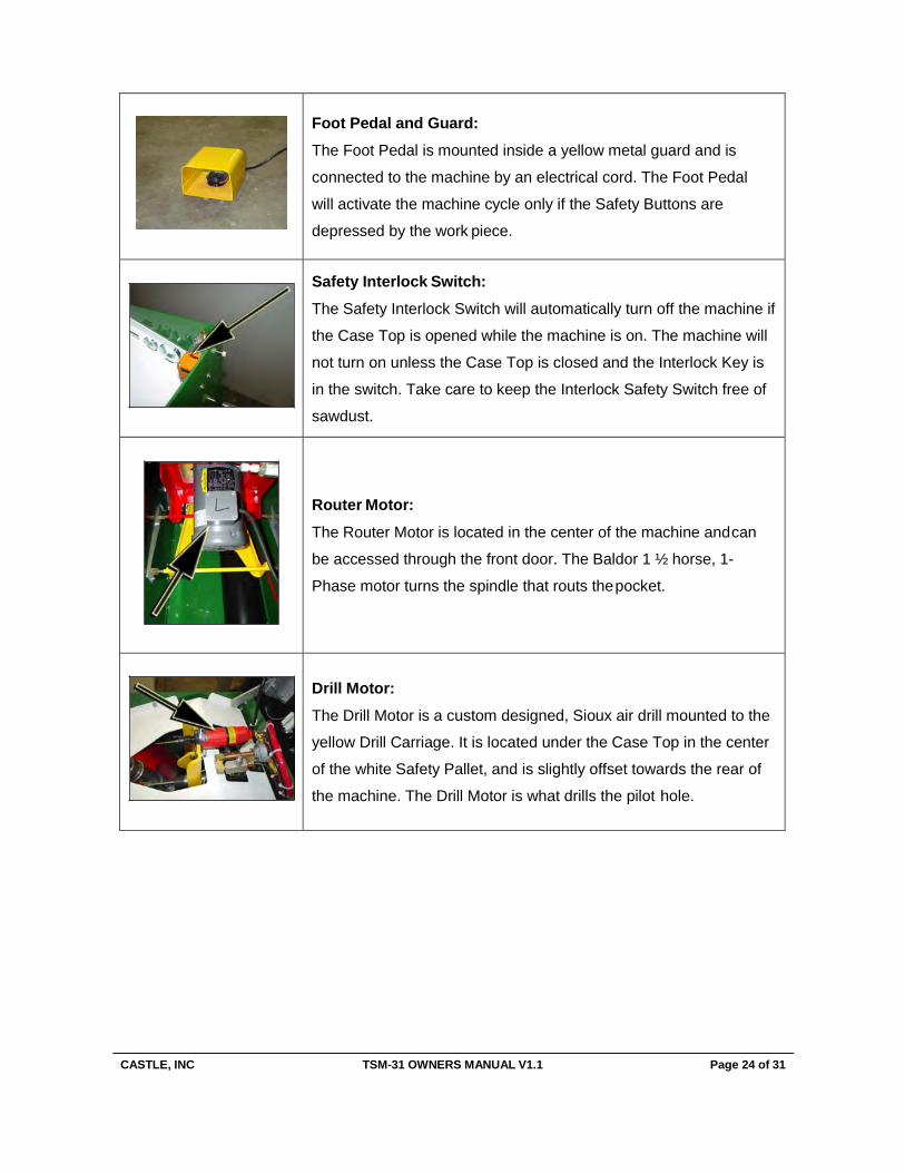
Foot Pedal and Guard: The Foot Pedal is mounted inside a yellow metal guard and is
connected to the machine by an electrical cord. The Foot Pedal
will activate the machine cycle only if the Safety Buttons are
depressed by the work piece.
Safety Interlock Switch: The Safety Interlock Switch will automatically turn off the machine if
the Case Top is opened while the machine is on. The machine will
not turn on unless the Case Top is closed and the Interlock Key is
in the switch. Take care to keep the Interlock Safety Switch free of
sawdust.
Router Motor:
The Router Motor is located in the center of the machine and can
be accessed through the front door. The Baldor 1 ½ horse, 1-
Phase motor turns the spindle that routs the pocket.
Drill Motor: The Drill Motor is a custom designed, Sioux air drill mounted to the
yellow Drill Carriage. It is located under the Case Top in the center
of the white Safety Pallet, and is slightly offset towards the rear of
the machine. The Drill Motor is what drills the pilot hole.
CASTLE, INC TSM-31 OWNERS MANUAL V1.1 Page 25 of 31
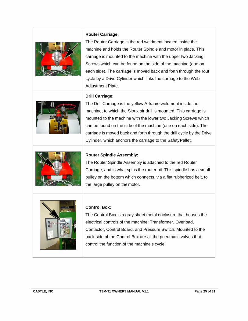
Router Carriage:
The Router Carriage is the red weldment located inside the
machine and holds the Router Spindle and motor in place. This
carriage is mounted to the machine with the upper two Jacking
Screws which can be found on the side of the machine (one on
each side). The carriage is moved back and forth through the rout
cycle by a Drive Cylinder which links the carriage to the Web
Adjustment Plate.
Drill Carriage:
The Drill Carriage is the yellow A-frame weldment inside the
machine, to which the Sioux air drill is mounted. This carriage is
mounted to the machine with the lower two Jacking Screws which
can be found on the side of the machine (one on each side). The
carriage is moved back and forth through the drill cycle by the Drive
Cylinder, which anchors the carriage to the Safety Pallet.
Router Spindle Assembly: The Router Spindle Assembly is attached to the red Router
Carriage, and is what spins the router bit. This spindle has a small
pulley on the bottom which connects, via a flat rubberized belt, to
the large pulley on the motor.
Control Box:
The Control Box is a gray sheet metal enclosure that houses the
electrical controls of the machine: Transformer, Overload,
Contactor, Control Board, and Pressure Switch. Mounted to the
back side of the Control Box are all the pneumatic valves that
control the function of the machine’s cycle.
CASTLE, INC TSM-31 OWNERS MANUAL V1.1 Page 26 of 31
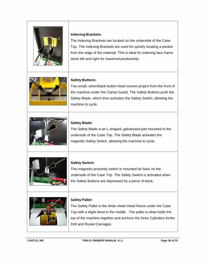
Indexing Brackets: The Indexing Brackets are located on the underside of the Case
Top. The Indexing Brackets are used for quickly locating a pocket
from the edge of the material. This is ideal for indexing face frame
stock left and right for maximum productivity.
Safety Buttons: Two small, silver/black button head screws project from the front of
the machine under the Clamp Guard. The Safety Buttons push the
Safety Blade, which then activates the Safety Switch, allowing the
machine to cycle.
Safety Blade: The Safety Blade is an L-shaped, galvanized part mounted to the
underside of the Case Top. The Safety Blade activates the
magnetic Safety Switch, allowing the machine to cycle.
Safety Switch:
This magnetic proximity switch is mounted far back on the
underside of the Case Top. The Safety Switch is activated when
the Safety Buttons are depressed by a piece of stock.
Safety Pallet: The Safety Pallet is the white sheet metal fixture under the Case
Top with a slight bend in the middle. The pallet is what holds the
top of the machine together and anchors the Drive Cylinders for the
Drill and Router Carriages.
CASTLE, INC TSM-31 OWNERS MANUAL V1.1 Page 27 of 31
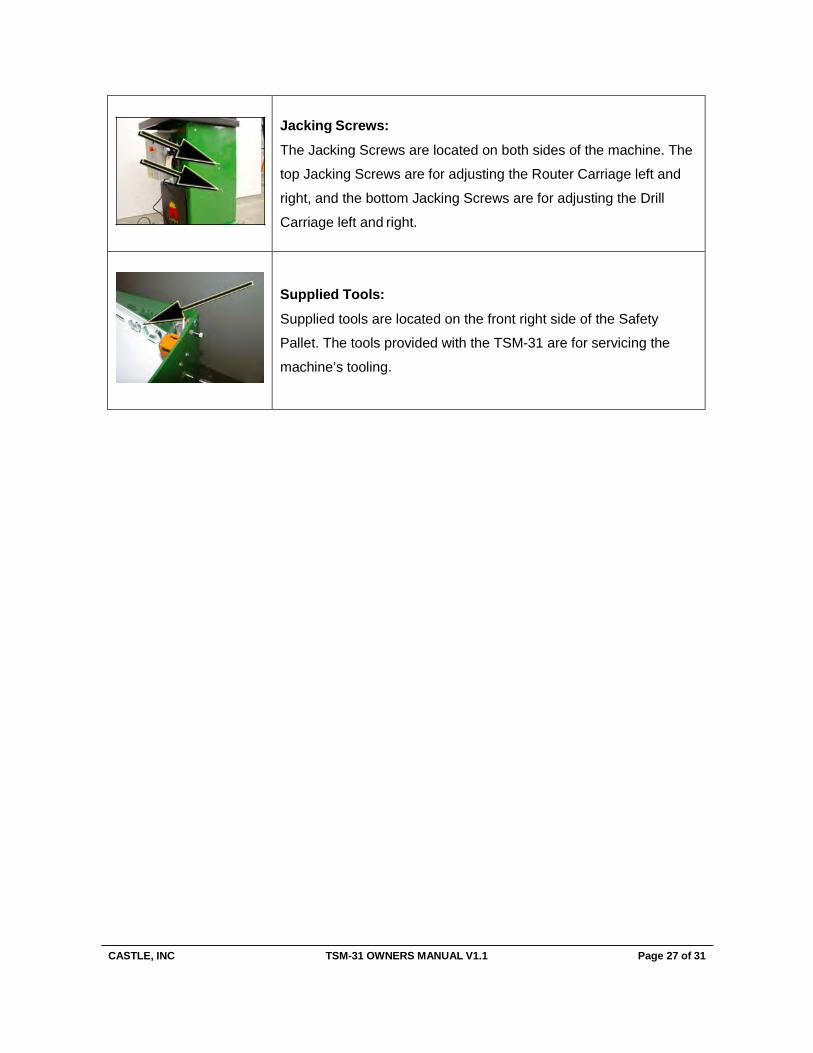
Jacking Screws:
The Jacking Screws are located on both sides of the machine. The
top Jacking Screws are for adjusting the Router Carriage left and
right, and the bottom Jacking Screws are for adjusting the Drill
Carriage left and right.
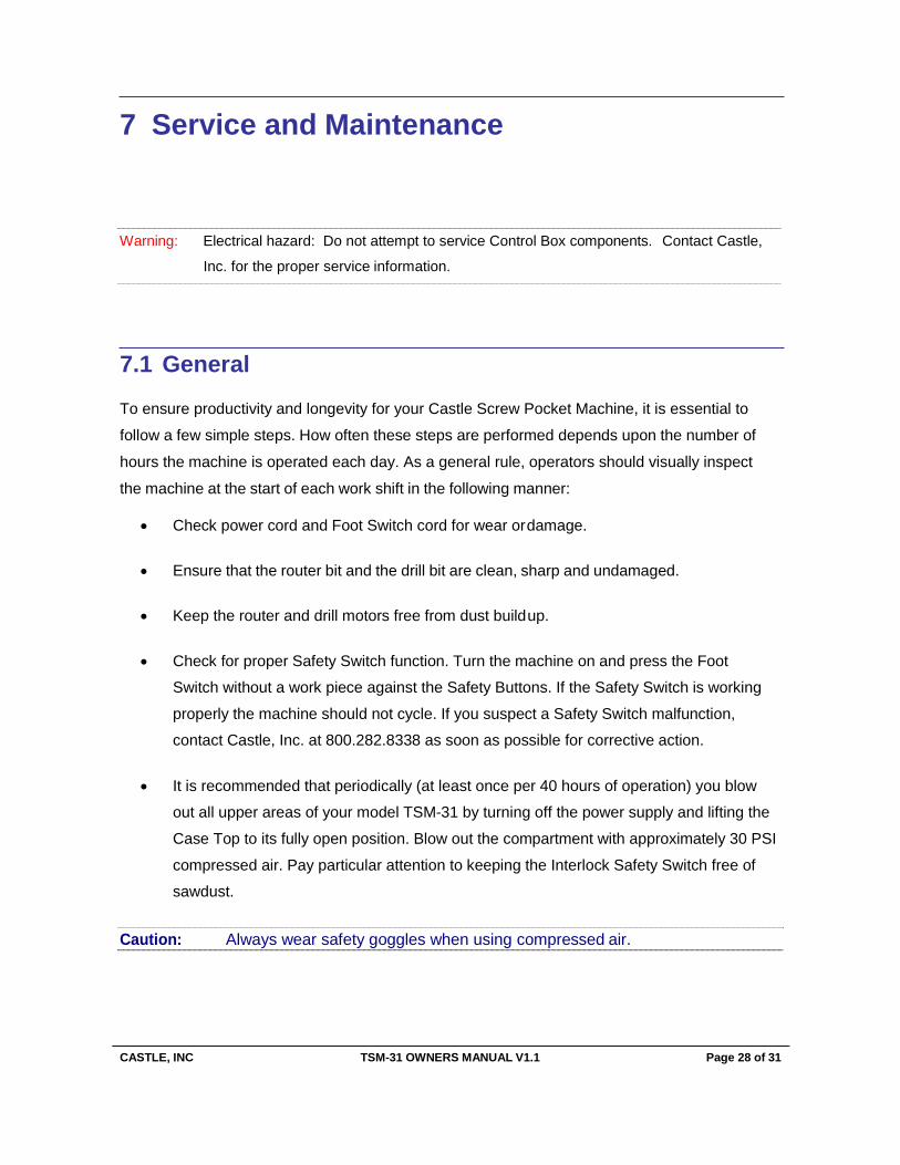
Supplied Tools:
Supplied tools are located on the front right side of the Safety
Pallet. The tools provided with the TSM-31 are for servicing the
machine’s tooling.
CASTLE, INC TSM-31 OWNERS MANUAL V1.1 Page 28 of 31
7 Service and Maintenance
Warning: Electrical hazard: Do not attempt to service Control Box components. Contact Castle,
Inc. for the proper service information.
7.1 General
To ensure productivity and longevity for your Castle Screw Pocket Machine, it is essential to
follow a few simple steps. How often these steps are performed depends upon the number of
hours the machine is operated each day. As a general rule, operators should visually inspect
the machine at the start of each work shift in the following manner:
• Check power cord and Foot Switch cord for wear or damage.
• Ensure that the router bit and the drill bit are clean, sharp and undamaged.
• Keep the router and drill motors free from dust build up.
• Check for proper Safety Switch function. Turn the machine on and press the Foot
Switch without a work piece against the Safety Buttons. If the Safety Switch is working
properly the machine should not cycle. If you suspect a Safety Switch malfunction,
contact Castle, Inc. at 800.282.8338 as soon as possible for corrective action.
• It is recommended that periodically (at least once per 40 hours of operation) you blow
out all upper areas of your model TSM-31 by turning off the power supply and lifting the
Case Top to its fully open position. Blow out the compartment with approximately 30 PSI
compressed air. Pay particular attention to keeping the Interlock Safety Switch free of
sawdust.
Caution: Always wear safety goggles when using compressed air.
CASTLE, INC TSM-31 OWNERS MANUAL V1.1 Page 29 of 31
Note: The model TSM-31 uses bearings that are pre-lubricated. No bearing lubrication is necessary. However, an automatic Lubricator is attached to the Air Regulator. Air tool oil must be kept in the Lubricator at all times.
• The Lubricator should be set so that a slight deposit of oil and dust occurs at the drill
motor exhaust. The exhaust is located in front of the drill motor behind the drill motor
collet.
• The oil / dust deposit should not occur until the machine has been run for at least 4
hours. If after 4 hours of use you don’t see this deposit, adjust the Lubricator knob on
the front of your machine counter clockwise about ¼ turn and run the machine again.
Keep adjusting until the deposit begins to show.
7.2 Motors and Bits
Because the motors are enclosed in the machine, it is important that the maintenance guidelines
provided in the manufacturer’s instruction manual be strictly observed.
• Periodically during operation, blow out the air passages on both motors with 30 PSI compressed air.
• To prolong motor life, and avoid costly downtime, a dust collection system must be used. A port has been provided on the rear of the machine for this purpose.
• To ensure safe and effective operation, make certain that there is at least 80PSI air
pressure to the machine. Check cycle time of machine for proper duration. A typical
cycle under normal conditions will last from 11/2 to 2 seconds. A cycle significantly longer than this may lead to excessive bit wear.
• It is suggested that a two flute, carbide tipped B00138 Castle bit be used when pocketing
particleboard, Melamine, MDF, etc. This leaves a clean cut and offers economically
longer bit life.
• When cutting pockets in solid woods such as maple, oak, ash or alder we recommend
the B00438 three flute HSS cobalt bit.
Caution: Always wear safety goggles when using compressed air.
CASTLE, INC TSM-31 OWNERS MANUAL V1.1 Page 30 of 31
• If pockets are being cut in both types of materials (i.e., particleboard and hard wood) or if
an exceptionally long bit life is desired, then it is suggested that the B00338 solid carbide
bit be used. All three bits are available through Castle, Inc.
• The pilot hole is made with a 9/64” drill bit, B02964. This size drill bit comes with your
machine. Also available are a 7/64” and 3/16” size drill bit.
• Feel free to contact your local Castle Dealer or our Parts Department TOLL FREE at
800-282-8338 for information and pricing on tooling and accessory products for your
TSM-31.
7.3 Serial Number Log
SERIAL NUMBER LOG
MANUFACTURER PART NUMBER SERIAL NO.
Castle, Inc. A00031 – TSM-31 Heavy Duty Screw Pocket Machine – Single Phase
Sioux P01957 – Sioux SDG75S25FCT Motor
Baldor E27301 – Baldor 3 HP Single Phase Motor
PURCHASE DATE:
CASTLE, INC TSM-31 OWNERS MANUAL V1.1 Page 31 of 31
8 Warranty Information Castle, Inc. uses only the highest quality materials available for the construction of our machines. Your TSM-31 is warranted for one (1) full year from the date of purchase against workmanship or material defects under normal use and service. Castle, Inc. is not responsible for failures or injuries due to negligence, misuse, alteration, unauthorized service, or accidents. Owners of new machines are obligated to contact their dealer AND Castle before contracting for, or attempting warranty repairs or service. If Castle or dealer technicians determine that reasonably simple adjustments or tests are necessary in delivering remedy to a failed machine, owners of warrantied machines are obligated to exercise due diligence while assisting in the execution of these simple adjustments or tests. When a problem cannot be resolved via telephone support, Castle will, at its expense, send replacement parts and instructions to the purchaser necessary to cure the defect. Castle will not be responsible for providing labor on repairs that are deemed reasonable for the owner to accomplish. Castle, Inc., at its sole discretion, will elect to either repair (by a Castle technician or dealer technician) or replace a machine in the case of warranty issues that exceed reasonable owner repair expectations. Alternatively, Castle will factory repair any machine provided the machine is returned to Castle, shipping prepaid, within the warranty period. Castle will not, under any circumstances, be liable for consequential, incidental, special or exemplary damages, or for loss of time, revenue or production. Further, Castle disclaims any warranty, expressed or implied, as to the merchantability or fitness of a Castle product for any particular purpose. 30 Day Refund Policy Any Castle machine that is un-altered and in almost new condition may be returned by the purchaser, for any reason, within 30 days of the purchase date for a full refund. Please contact your Castle authorized dealer for more information.
For Technical Assistance, Parts & Tooling:
Call 800-282-8338, Monday through Friday, 8:00am - 4:00pm, Pacific Time
Fax: 707-765-0953
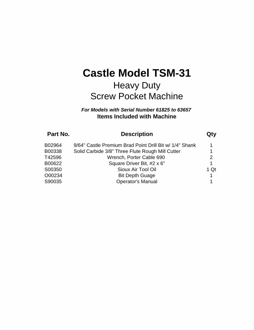
Castle Model TSM-31
Heavy Duty
Screw Pocket Machine
For Models with Serial Number 61825 to 63657
Items Included with Machine
Part No. Description Qty
B02964 9/64" Castle Premium Brad Point Drill Bit w/ 1/4" Shank 1 B00338 Solid Carbide 3/8" Three Flute Rough Mill Cutter 1 T42596 Wrench, Porter Cable 690 2 B00622 Square Driver Bit, #2 x 6" 1 S00350 Sioux Air Tool Oil 1 Qt O00234 Bit Depth Guage 1 S90035 Operator's Manual 1
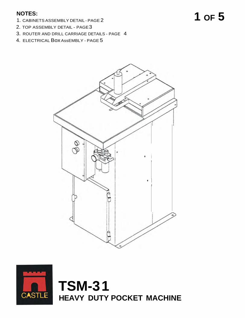
NOTES: 1. CABINETS ASSEMBLY DETAIL - PAGE 2 2. TOP ASSEMBLY DETAIL - PAGE 3 3. ROUTER AND DRILL CARRIAGE DETAILS - PAGE 4 4. ELECTRICAL Box AssEMBLY - PAGE 5
1 OF 5
TSM-3 1 HEAVY DUTY POCKET MACHINE
• i i
• I I
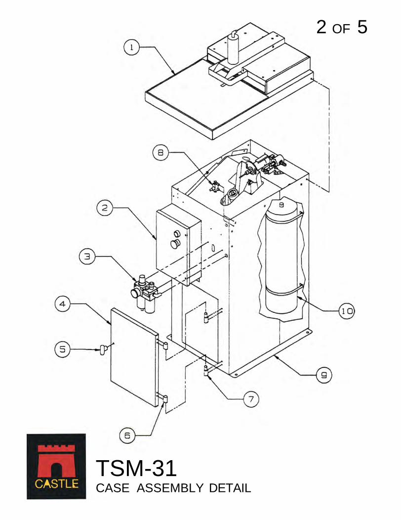
2 OF 5
TSM-31 CASE ASSEMBLY DETAIL
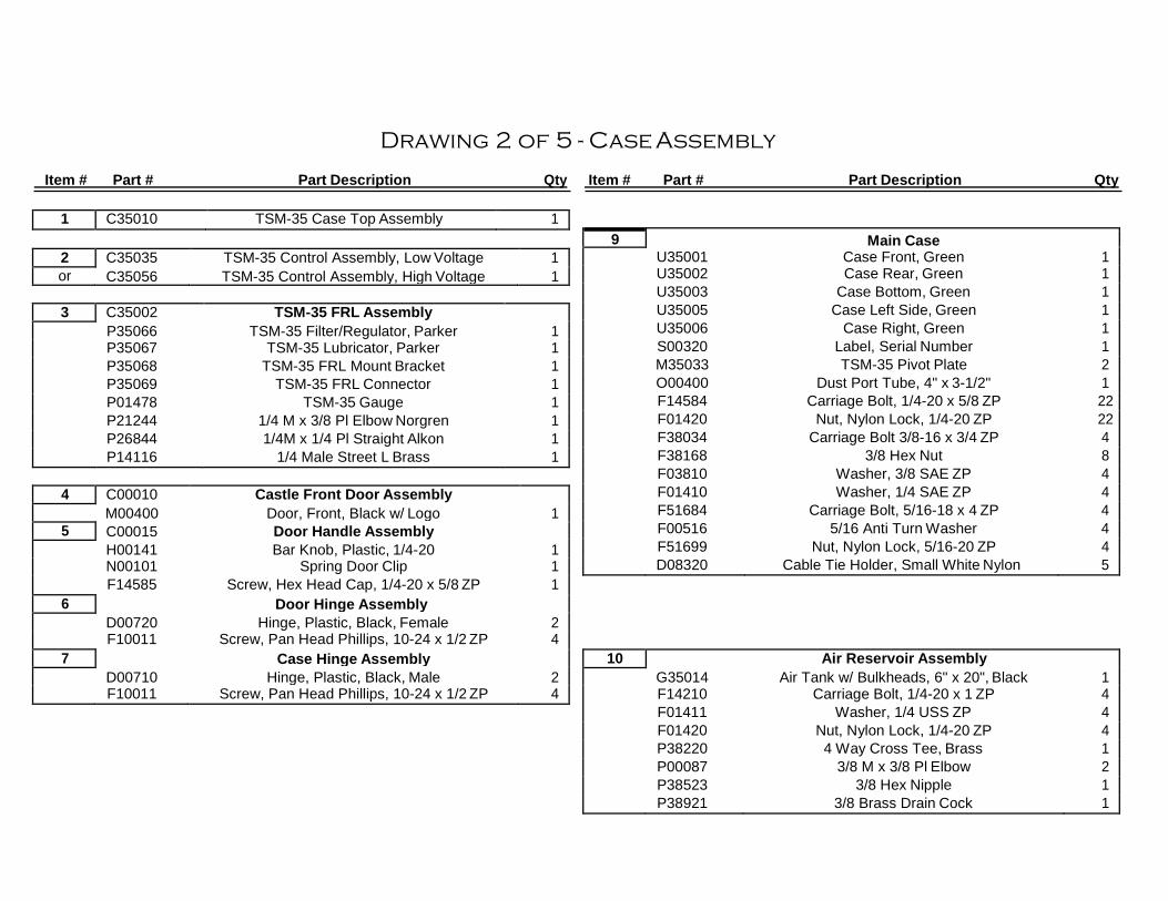
Drawing 2 of 5 - Case Assembly
Item # Part # Part Description Qty Item # Part # Part Description Qty
9 Main Case U35001 Case Front, Green 1 U35002 Case Rear, Green 1 U35003 Case Bottom, Green 1 U35005 Case Left Side, Green 1 U35006 Case Right, Green 1 S00320 Label, Serial Number 1 M35033 TSM-35 Pivot Plate 2 O00400 Dust Port Tube, 4" x 3-1/2" 1 F14584 Carriage Bolt, 1/4-20 x 5/8 ZP 22 F01420 Nut, Nylon Lock, 1/4-20 ZP 22 F38034 Carriage Bolt 3/8-16 x 3/4 ZP 4 F38168 3/8 Hex Nut 8 F03810 Washer, 3/8 SAE ZP 4 F01410 Washer, 1/4 SAE ZP 4 F51684 Carriage Bolt, 5/16-18 x 4 ZP 4 F00516 5/16 Anti Turn Washer 4 F51699 Nut, Nylon Lock, 5/16-20 ZP 4 D08320 Cable Tie Holder, Small White Nylon 5
1 C35010 TSM-35 Case Top Assembly 1
2 C35035 TSM-35 Control Assembly, Low Voltage 1 or C35056 TSM-35 Control Assembly, High Voltage 1
3 C35002 TSM-35 FRL Assembly
P35066 TSM-35 Filter/Regulator, Parker 1 P35067 TSM-35 Lubricator, Parker 1 P35068 TSM-35 FRL Mount Bracket 1 P35069 TSM-35 FRL Connector 1 P01478 TSM-35 Gauge 1 P21244 1/4 M x 3/8 Pl Elbow Norgren 1 P26844 1/4M x 1/4 Pl Straight Alkon 1 P14116 1/4 Male Street L Brass 1
4 C00010 Castle Front Door Assembly M00400 Door, Front, Black w/ Logo 1
5 C00015 Door Handle Assembly H00141 Bar Knob, Plastic, 1/4-20 1 N00101 Spring Door Clip 1 F14585 Screw, Hex Head Cap, 1/4-20 x 5/8 ZP 1
6 Door Hinge Assembly D00720 Hinge, Plastic, Black, Female 2 F10011 Screw, Pan Head Phillips, 10-24 x 1/2 ZP 4
7 Case Hinge Assembly D00710 Hinge, Plastic, Black, Male 2 F10011 Screw, Pan Head Phillips, 10-24 x 1/2 ZP 4
10 Air Reservoir Assembly G35014 Air Tank w/ Bulkheads, 6" x 20", Black 1 F14210 Carriage Bolt, 1/4-20 x 1 ZP 4 F01411 Washer, 1/4 USS ZP 4 F01420 Nut, Nylon Lock, 1/4-20 ZP 4 P38220 4 Way Cross Tee, Brass 1 P00087 3/8 M x 3/8 Pl Elbow 2 P38523 3/8 Hex Nipple 1 P38921 3/8 Brass Drain Cock 1

8 Router Feed Rate Control P00117 Valve, Flow Control, SMC NAS-2000-N01 1 P18165 Fitting, 1/8 NPT x 1/16 Side Out Barb, Brass 1 P18161 Fitting, 1/8 NPT x 1/16 Barb, White Nylon 1 F08112 Screw, Pan Phillips, 8-32 x 1-1/2 ZP 2 F08032 Nut, Nylon Lock 8-32 2
3 OF 5
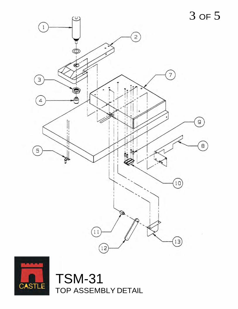
TSM-31 TOP ASSEMBLY DETAIL

Drawing 3 of 5 - Top Assembly
Item # Part # Part Description Qty Item # Part # Part Description Qty
11,12,13 Lid Catch Mounting Assembly U35040 Lid Catch, Plated 1 F14225 Carriage Bolt, 1/4-20 x 1 ZP 2 F01410 Washer, 1/4 SAE ZP 6 F01420 Nut, Nylon Lock, 1/4-20 ZP 2 N38314 Spacer, Steel, 3/8 OD x 1/4 ID x 5/16 L ZP 2
1 Clamp Cylinder P00215 Cylinder Spring Return,2"Bore,1.5"Stroke,SS Rod 1 F12222 1/2-20 Hex Jam Nut 1 P14414 Fitting, 1/4 NPT x 1/4 Push In Elbow 1 H10138 Washer, Fiber, 1-3/8 ID 1
Case Top Hinge Assembly F38118 Shoulder Bolt 3/8 x 1-1/2 2 F51699 Nut, Nylon Lock, 5/16-18 ZP 2 F03810 Washer, 3/8 SAE ZP 2
8 C35101 Safety Switch / Blade Assembly
M35016 TSM-35 Safety Blade 1 F10358 Screw, Button Head Socket, 10-32 x 5/8 Bk Oxide 3 F10322 Nut, Hex Jam, 10-32 ZP 1 F01420 Nut, Nylon Lock, 1/4-20 ZP 2
2 Clamp Guard M00210 TSM Clamp Guard, Yellow 1 F14234 Carriage Bolt, 1/4-20 x 1-3/4 ZP 1 F01410 Washer, 1/4 SAE ZP 1 F01420 Nut, Nylon Lock, 1/4-20 ZP 1 F14378 Screw, Button Head Socket,1/4-20x7/8, BkOxide 2 F14201 Nut, Pem Self Clinching, 1/4-20 #1 2
9 Safety Switch Mounting Assembly F08122 Screw, Pan Phillips Machine, 8-32 x 1-1/2 ZP 4 F08032 Nut, Nylon Lock, 8-32 ZP 4 N38314 3/8 OD x 1/4 ID x 5/16L Spacer 2 D38507 #8 Spacer, Nylon, 3/8 OD x 7/8" L 4
3 F11412 Nut, Hex Jam 1-1/4-12 ZP 1
4 C00200 Clamp Foot Assembly N21351 Clamp Foot, Small Zinc Plated 1 N70118 Pad, Polyurethane 1-1/8" 1
10 Safety Switch E10850 1085TW Magnet and Magnetic Reed Switch 1 E22708 Wire, 22AWG, 2 Strand, Grey Jacketed 64" P38012 Tubing, 3/8 OD Black Polyethelene 22"
5 Safety Interlock Key E03322 Key, Security Interlock, ABB LSA30 1 F08032 Nut, Nylon Lock, 8-32 ZP 2
7 C35010 Main Case Top U35102 Case Top, Black 1 C00350 Case Top Laminate, Dolphin Grey 1 C00210 Face Plate Laminate, Dolphin Grey 1 S00301 Label, Warning, Keep Hands Clear, Lexan 1
I
4 OF 5
' '
!: I : I I
l
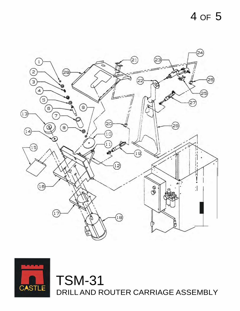
TSM-31 DRILL AND ROUTER CARRIAGE ASSEMBLY
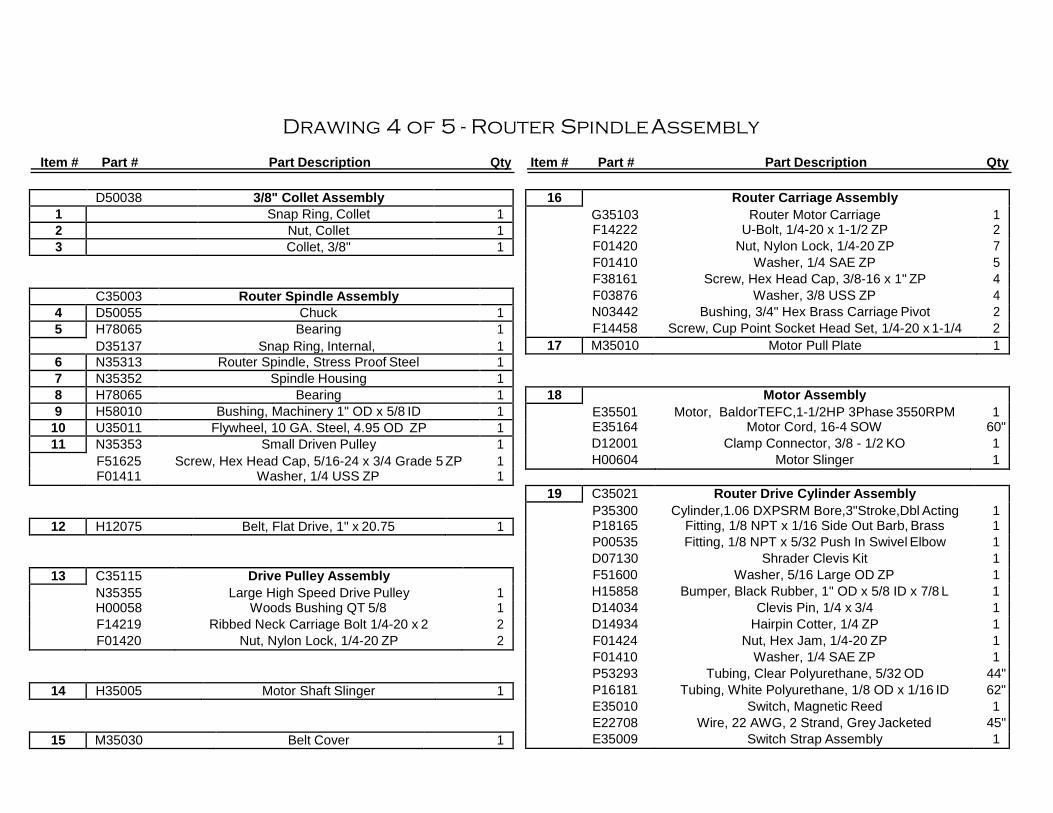
Drawing 4 of 5 - Router Spindle Assembly
Item # Part # Part Description Qty Item # Part # Part Description Qty
19 C35021 Router Drive Cylinder Assembly P35300 Cylinder,1.06 DXPSRM Bore,3"Stroke,Dbl Acting 1 P18165 Fitting, 1/8 NPT x 1/16 Side Out Barb, Brass 1 P00535 Fitting, 1/8 NPT x 5/32 Push In Swivel Elbow 1 D07130 Shrader Clevis Kit 1 F51600 Washer, 5/16 Large OD ZP 1 H15858 Bumper, Black Rubber, 1" OD x 5/8 ID x 7/8 L 1 D14034 Clevis Pin, 1/4 x 3/4 1 D14934 Hairpin Cotter, 1/4 ZP 1 F01424 Nut, Hex Jam, 1/4-20 ZP 1 F01410 Washer, 1/4 SAE ZP 1 P53293 Tubing, Clear Polyurethane, 5/32 OD 44" P16181 Tubing, White Polyurethane, 1/8 OD x 1/16 ID 62" E35010 Switch, Magnetic Reed 1 E22708 Wire, 22 AWG, 2 Strand, Grey Jacketed 45" E35009 Switch Strap Assembly 1
D50038 3/8" Collet Assembly 1 Snap Ring, Collet 1 2 Nut, Collet 1 3 Collet, 3/8" 1
16 Router Carriage Assembly G35103 Router Motor Carriage 1 F14222 U-Bolt, 1/4-20 x 1-1/2 ZP 2 F01420 Nut, Nylon Lock, 1/4-20 ZP 7 F01410 Washer, 1/4 SAE ZP 5 F38161 Screw, Hex Head Cap, 3/8-16 x 1" ZP 4 F03876 Washer, 3/8 USS ZP 4 N03442 Bushing, 3/4" Hex Brass Carriage Pivot 2 F14458 Screw, Cup Point Socket Head Set, 1/4-20 x 1-1/4 2
17 M35010 Motor Pull Plate 1
C35003 Router Spindle Assembly 4 D50055 Chuck 1 5 H78065 Bearing 1
D35137 Snap Ring, Internal, 1 6 N35313 Router Spindle, Stress Proof Steel 1 7 N35352 Spindle Housing 1 8 H78065 Bearing 1 9 H58010 Bushing, Machinery 1" OD x 5/8 ID 1
10 U35011 Flywheel, 10 GA. Steel, 4.95 OD ZP 1 11 N35353 Small Driven Pulley 1
F51625 Screw, Hex Head Cap, 5/16-24 x 3/4 Grade 5 ZP 1 F01411 Washer, 1/4 USS ZP 1
18 Motor Assembly E35501 Motor, BaldorTEFC,1-1/2HP 3Phase 3550RPM 1 E35164 Motor Cord, 16-4 SOW 60" D12001 Clamp Connector, 3/8 - 1/2 KO 1 H00604 Motor Slinger 1
12 H12075 Belt, Flat Drive, 1" x 20.75 1
13 C35115 Drive Pulley Assembly N35355 Large High Speed Drive Pulley 1 H00058 Woods Bushing QT 5/8 1 F14219 Ribbed Neck Carriage Bolt 1/4-20 x 2 2 F01420 Nut, Nylon Lock, 1/4-20 ZP 2
14 H35005 Motor Shaft Slinger 1
15 M35030 Belt Cover 1
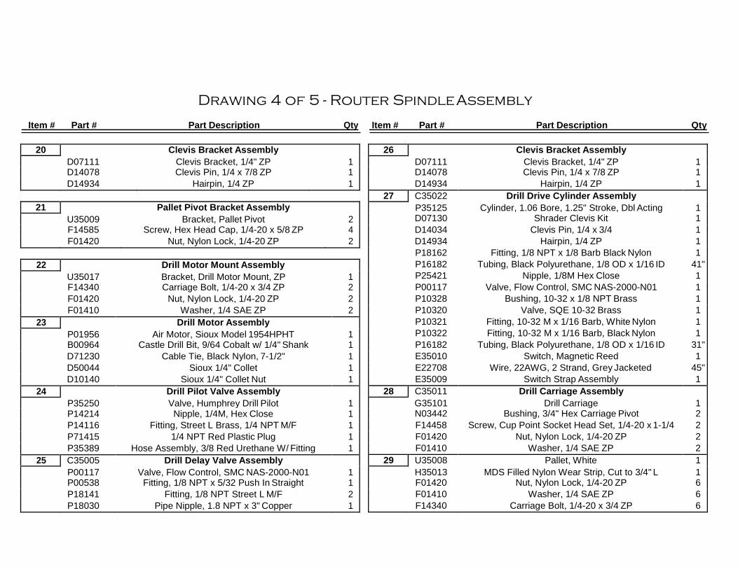
Drawing 4 of 5 - Router Spindle Assembly
Item # Part # Part Description Qty Item # Part # Part Description Qty
26 Clevis Bracket Assembly
D07111 Clevis Bracket, 1/4" ZP 1 D14078 Clevis Pin, 1/4 x 7/8 ZP 1 D14934 Hairpin, 1/4 ZP 1
27 C35022 Drill Drive Cylinder Assembly P35125 Cylinder, 1.06 Bore, 1.25" Stroke, Dbl Acting 1 D07130 Shrader Clevis Kit 1 D14034 Clevis Pin, 1/4 x 3/4 1 D14934 Hairpin, 1/4 ZP 1 P18162 Fitting, 1/8 NPT x 1/8 Barb Black Nylon 1 P16182 Tubing, Black Polyurethane, 1/8 OD x 1/16 ID 41" P25421 Nipple, 1/8M Hex Close 1 P00117 Valve, Flow Control, SMC NAS-2000-N01 1 P10328 Bushing, 10-32 x 1/8 NPT Brass 1 P10320 Valve, SQE 10-32 Brass 1 P10321 Fitting, 10-32 M x 1/16 Barb, White Nylon 1 P10322 Fitting, 10-32 M x 1/16 Barb, Black Nylon 1 P16182 Tubing, Black Polyurethane, 1/8 OD x 1/16 ID 31" E35010 Switch, Magnetic Reed 1 E22708 Wire, 22AWG, 2 Strand, Grey Jacketed 45" E35009 Switch Strap Assembly 1
28 C35011 Drill Carriage Assembly G35101 Drill Carriage 1 N03442 Bushing, 3/4" Hex Carriage Pivot 2 F14458 Screw, Cup Point Socket Head Set, 1/4-20 x 1-1/4 2 F01420 Nut, Nylon Lock, 1/4-20 ZP 2 F01410 Washer, 1/4 SAE ZP 2
29 U35008 Pallet, White 1 H35013 MDS Filled Nylon Wear Strip, Cut to 3/4" L 1 F01420 Nut, Nylon Lock, 1/4-20 ZP 6 F01410 Washer, 1/4 SAE ZP 6 F14340 Carriage Bolt, 1/4-20 x 3/4 ZP 6
20 Clevis Bracket Assembly D07111 Clevis Bracket, 1/4" ZP 1 D14078 Clevis Pin, 1/4 x 7/8 ZP 1 D14934 Hairpin, 1/4 ZP 1
21 Pallet Pivot Bracket Assembly U35009 Bracket, Pallet Pivot 2 F14585 Screw, Hex Head Cap, 1/4-20 x 5/8 ZP 4 F01420 Nut, Nylon Lock, 1/4-20 ZP 2
22 Drill Motor Mount Assembly U35017 Bracket, Drill Motor Mount, ZP 1 F14340 Carriage Bolt, 1/4-20 x 3/4 ZP 2 F01420 Nut, Nylon Lock, 1/4-20 ZP 2 F01410 Washer, 1/4 SAE ZP 2
23 Drill Motor Assembly P01956 Air Motor, Sioux Model 1954HPHT 1 B00964 Castle Drill Bit, 9/64 Cobalt w/ 1/4" Shank 1 D71230 Cable Tie, Black Nylon, 7-1/2" 1 D50044 Sioux 1/4" Collet 1 D10140 Sioux 1/4" Collet Nut 1
24 Drill Pilot Valve Assembly P35250 Valve, Humphrey Drill Pilot 1 P14214 Nipple, 1/4M, Hex Close 1 P14116 Fitting, Street L Brass, 1/4 NPT M/F 1 P71415 1/4 NPT Red Plastic Plug 1 P35389 Hose Assembly, 3/8 Red Urethane W/ Fitting 1
25 C35005 Drill Delay Valve Assembly P00117 Valve, Flow Control, SMC NAS-2000-N01 1 P00538 Fitting, 1/8 NPT x 5/32 Push In Straight 1 P18141 Fitting, 1/8 NPT Street L M/F 2 P18030 Pipe Nipple, 1.8 NPT x 3" Copper 1
\ \ \ '
/"'1 .
\ \
I \ I 1. ; \ \ I I .
5 0F 5
\I \I I, , ' I
\ / -- 1 1 1 \/ \ ' !
-- . . ' ,,. "' i I • i "I
i J I ' I
I
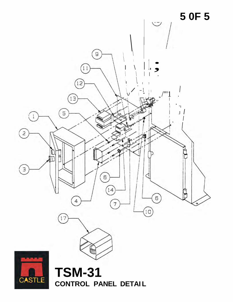
TSM-31 CONTROL PANEL DETAI L
I

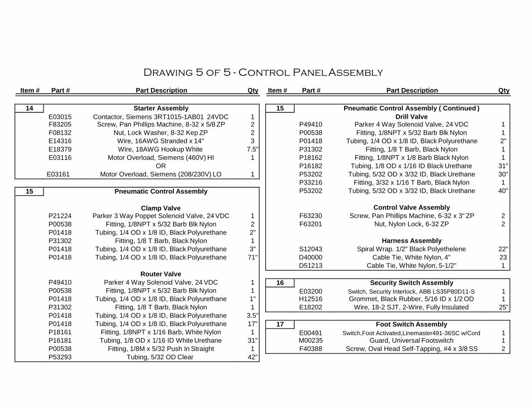
Drawing 5 of 5 - Control Panel Assembly
Item # Part # Part Description Qty Item # Part # Part Description Qty
13 Transformer Assembly E35713 Transformer,50VA,Multi-Input,24VAC Output 1 E16224 Fuse, 250V 1 D82218 Vinyl Spade Lug, 22-18 #8 2 E18373 Wire, 18AWG Hookup Blue 16.5" E18371 Wire, 18AWG Hookup Grey 17 D81614 Vinyl Spade Lug, 16-14 #8 2 D61614 Vinyl Ring Lug, 16-14 #8 1 E18374 Wire, 18AWG Hookup Orange 27" F08324 Screw, Pan Phillips Machine, 8-32 x 3/4 ZP 3 F08100 Screw, Pan Phillips Machine, 8-32 x 1" ZP 1 F08132 Nut, Lock Washer, 8-32 Kep ZP 4
1 Control Panel Enclosure Assembly M00134 Control Panel Enclosure 1 F14225 Screw, Hex Head Cap. 1/4-20 x 1 ZP 4 F01420 Nut, Nylon Lock, 1/4-20 ZP 4 S17578 Label, Caution, "Wear Safety Glasses" 1 S13264 Label, Warning, "Danger Electrical Hazard" 1 S11635 Label, "Made in USA" 1 S35002 Label, Wiring Diagram 1 D06627 Cable Tie Anchor, White Nylon, W/ Adhesive 2
9 Pressure Sensor Switch E35420 Switch, Air Pressure Sensing 1 D22181 Terminal, 22-18 Fully Insulated, Female 2 P33228 Fitting, 10-32 x 1/16 Barb, Black Nylon 1 P01418 Tubing, 1/4 OD x 1/8 ID, Black Urethane 1"
10 F38241 Nut, Hex Jam, 3/8-24 ZP 1
11 Control Panel Back Plate M35013 Control Panel Back Plate 1 F14212 Carriage Bolt, 1/4-20 x 1/2 ZP 2 F01423 Nut, Hex, 1/4-20 ZP 2
2 C30351 Start Switch Actuator Assembly E03041 3SB3000-0AA41 Start Switch 1 E03400 Normally Open Contact Block 1 12 Contol Panel Back Plate Slot Cover
M00130 Back Plate Slot Cover 1 F08324 Screw, Pan Phillips Machine, 8-32 x 3/4 ZP 4 F08132 Nut, Lock Washer, 8-32 Kep ZP 4 S11436 Tape, PVC Foam S/A 1-1/4" 7.2"
3 C30352 Stop Switch Actuator Assembly E03000 3SB3000-1XA20 Stop Switch 1 E03401 Normally Closed Contact Block 1
4 E35424 Control Board, EL-35D 1
5 Control Board Mounting Assembly D08012 1/4 x 1/2 #8 Plastic Spacer 4 F08100 Screw, Pan Head Phillips, 8-32 x 1 ZP 4 F08132 Nut, Lock Washer, 8-32 Kep ZP 4
6 D12001 Clamp Connector & Nut, Romex 3/8-1/2 KO 1
7 H12516 Grommet, Black Rubber, 5/16 ID x 1/2 OD 1
8 Strain Relief D49600 90 Degree Cord Grip 1 E03185 1/2 Conduit Locknut 1
Drawing 5 of 5 - Control Panel Assembly
Item # Part # Part Description Qty Item # Part # Part Description Qty
14 Starter Assembly E03015 Contactor, Siemens 3RT1015-1AB01 24VDC 1 F83205 Screw, Pan Phillips Machine, 8-32 x 5/8 ZP 2 F08132 Nut, Lock Washer, 8-32 Kep ZP 2 E14316 Wire, 16AWG Stranded x 14" 3 E18379 Wire, 18AWG Hookup White 7.5" E03116 Motor Overload, Siemens (460V) HI 1 OR E03161 Motor Overload, Siemens (208/230V) LO 1
15 Pneumatic Control Assembly ( Continued ) Drill Valve P49410 Parker 4 Way Solenoid Valve, 24 VDC 1 P00538 Fitting, 1/8NPT x 5/32 Barb Blk Nylon 1 P01418 Tubing, 1/4 OD x 1/8 ID, Black Polyurethane 2" P31302 Fitting, 1/8 T Barb, Black Nylon 1 P18162 Fitting, 1/8NPT x 1/8 Barb Black Nylon 1 P16182 Tubing, 1/8 OD x 1/16 ID Black Urethane 31" P53202 Tubing, 5/32 OD x 3/32 ID, Black Urethane 30" P33216 Fitting, 3/32 x 1/16 T Barb, Black Nylon 1 P53202 Tubing, 5/32 OD x 3/32 ID, Black Urethane 40"
Control Valve Assembly
F63230 Screw, Pan Phillips Machine, 6-32 x 3" ZP 2 F63201 Nut, Nylon Lock, 6-32 ZP 2
Harness Assembly
S12043 Spiral Wrap. 1/2" Black Polyethelene 22" D40000 Cable Tie, White Nylon, 4" 23 D51213 Cable Tie, White Nylon, 5-1/2" 1
15 Pneumatic Control Assembly
Clamp Valve
P21224 Parker 3 Way Poppet Solenoid Valve, 24 VDC 1 P00538 Fitting, 1/8NPT x 5/32 Barb Blk Nylon 2 P01418 Tubing, 1/4 OD x 1/8 ID, Black Polyurethane 2" P31302 Fitting, 1/8 T Barb, Black Nylon 1 P01418 Tubing, 1/4 OD x 1/8 ID, Black Polyurethane 3" P01418 Tubing, 1/4 OD x 1/8 ID, Black Polyurethane 71"
Router Valve
P49410 Parker 4 Way Solenoid Valve, 24 VDC 1 P00538 Fitting, 1/8NPT x 5/32 Barb Blk Nylon 1 P01418 Tubing, 1/4 OD x 1/8 ID, Black Polyurethane 1" P31302 Fitting, 1/8 T Barb, Black Nylon 1 P01418 Tubing, 1/4 OD x 1/8 ID, Black Polyurethane 3.5" P01418 Tubing, 1/4 OD x 1/8 ID, Black Polyurethane 17" P18161 Fitting, 1/8NPT x 1/16 Barb, White Nylon 1 P16181 Tubing, 1/8 OD x 1/16 ID White Urethane 31" P00538 Fitting, 1/8M x 5/32 Push In Straight 1 P53293 Tubing, 5/32 OD Clear 42"
16 Security Switch Assembly E03200 Switch, Security Interlock, ABB LS35P80D11-S 1 H12516 Grommet, Black Rubber, 5/16 ID x 1/2 OD 1 E18202 Wire, 18-2 SJT, 2-Wire, Fully Insulated 25"
17 Foot Switch Assembly E00491 Switch,Foot Activated,Linemaster491-36SC w/Cord 1 M00235 Guard, Universal Footswitch 1 F40388 Screw, Oval Head Self-Tapping, #4 x 3/8 SS 2