Embed Size (px)
Citation preview

®DATA SHEETCHD01_03 Issue 03, 30th October 2020
LinACE™ is an extremely robust absolute linear cylindrical encoder system designed to be integrated into the servomechanism as a transducer, providing accurate measurements with excellent resolution and repeatability. It can be used as a control device or integrated directly into hydraulic, pneumatic, electromechanical actuators and linear motors as a position or velocity feedback element. The encoders are available in asynchronous serial over RS422, PWM, SSI and BiSS output versions and offer a range of selectable resolutions from 10 μm to 0.5 μm with speeds up to 5 m/s. The position of the encoder is maintained even if the shaft rotates during forward and backward movement.
Features and benefits
LinACETM
InAxis Linear AbsoluteMagnetic Shaft Encoder
⯈ True absolute system
⯈ Resolutions up to 0.5 μm
⯈ Measuring lengths up to 450 mm
⯈ Built-in self monitoring
⯈ Excellent resistance to stray magnetic fields
⯈ Non-magnetised hard chrome plated coded shaft
⯈ Suitable for highly dynamic control loops
⯈ Small footprint
TRUE ABSOLUTE
SYSTEM
ACCURACY UP TO ±5 µm
INTEGRAL BEARINGS
MACHINE TOOL INDUSTRIAL AUTOMATION
PROCESS AND CONTROLMEDICAL SERVO
MECHANISMS
General information
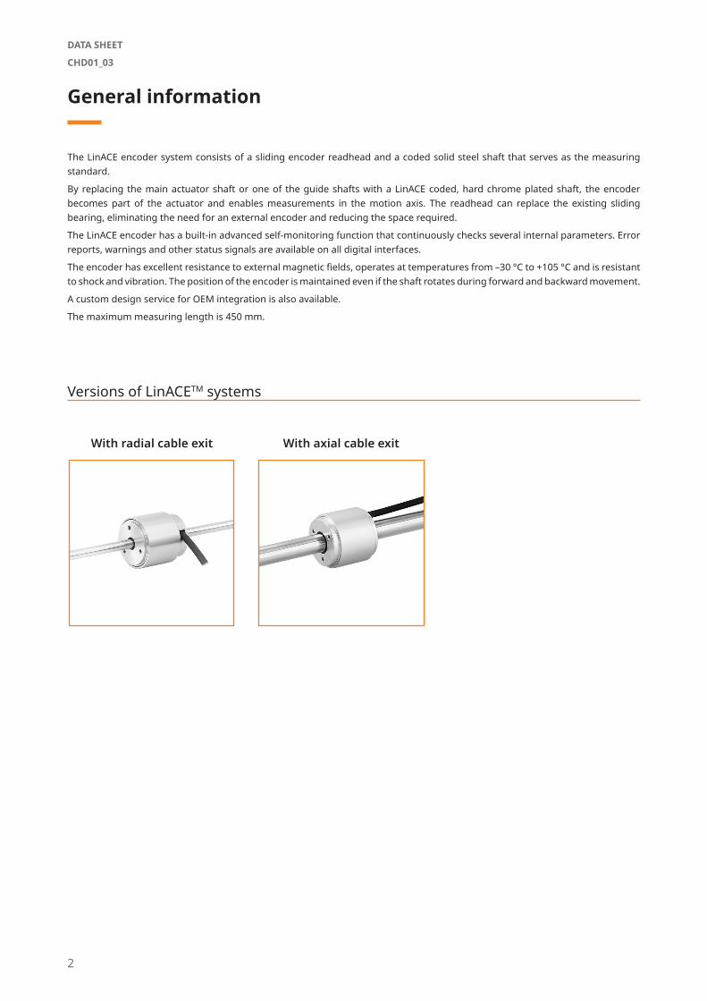
The LinACE encoder system consists of a sliding encoder readhead and a coded solid steel shaft that serves as the measuring standard.
By replacing the main actuator shaft or one of the guide shafts with a LinACE coded, hard chrome plated shaft, the encoder becomes part of the actuator and enables measurements in the motion axis. The readhead can replace the existing sliding bearing, eliminating the need for an external encoder and reducing the space required.
The LinACE encoder has a built-in advanced self-monitoring function that continuously checks several internal parameters. Error reports, warnings and other status signals are available on all digital interfaces.
The encoder has excellent resistance to external magnetic fields, operates at temperatures from –30 °C to +105 °C and is resistant to shock and vibration. The position of the encoder is maintained even if the shaft rotates during forward and backward movement.
A custom design service for OEM integration is also available.
The maximum measuring length is 450 mm.
With radial cable exit With axial cable exit
Versions of LinACETM systems
2
DATA SHEET
CHD01_03
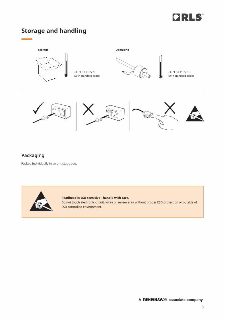
Storage and handling
Packaging
Storage Operating
–30 °C to +105 °C(with standard cable)
Readhead is ESD sensitive - handle with care. Do not touch electronic circuit, wires or sensor area without proper ESD protection or outside of ESD controlled environment.
–30 °C to +105 °C(with standard cable)
Packed individually in an antistatic bag.
3
®
A associate company
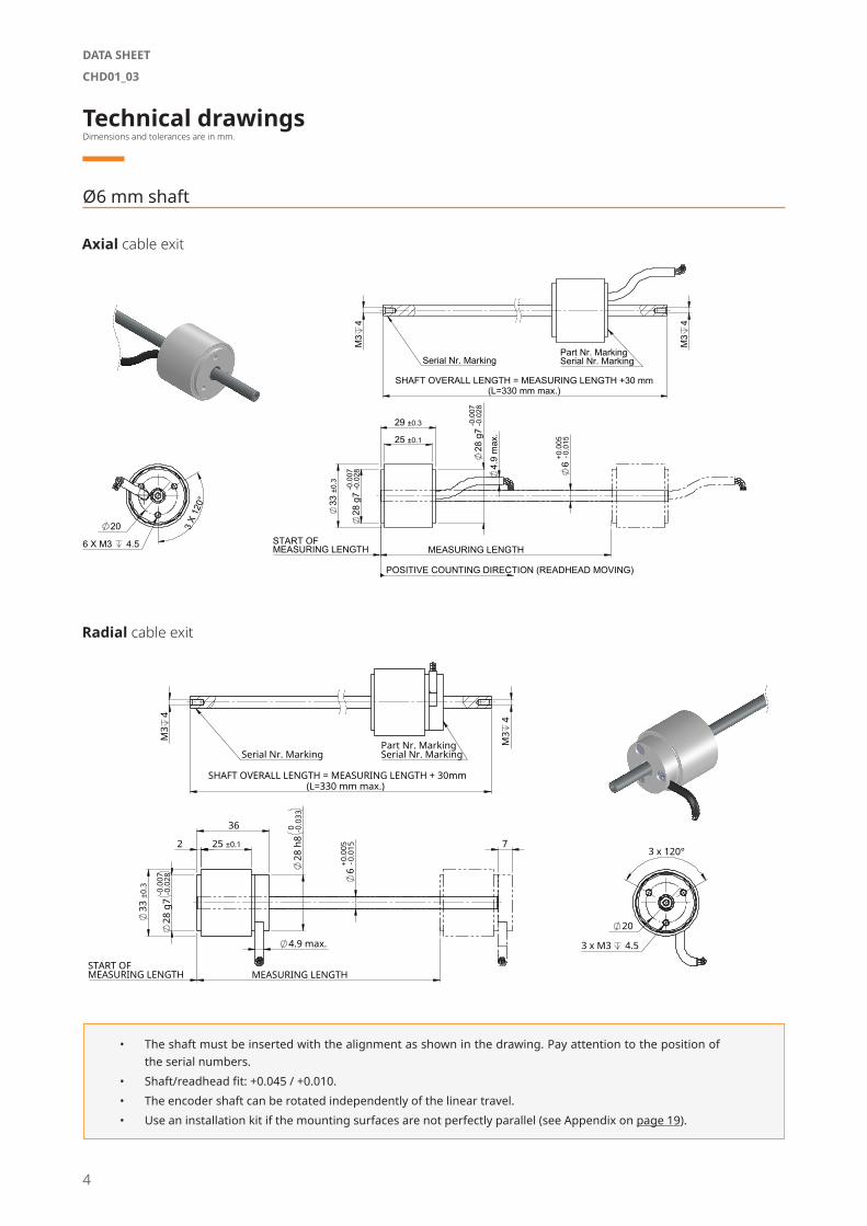
Technical drawingsDimensions and tolerances are in mm.
Ø6 mm shaft
Axial cable exit
Radial cable exit
7
28
g7
- -0.00
70.
028
33
±0.3
28
h8
-0 0.03
3
4.9 max.
6
+ -0.00
50.
015 2 25 ±0.1
36
MEASURING LENGTH
3 x 120°
3 x M3 4.5
20
SHAFT OVERALL LENGTH = MEASURING LENGTH + 30mm (L=330 mm max.)
M3
4
M3
4
Part Nr. MarkingSerial Nr. Marking Serial Nr. Marking
START OFMEASURING LENGTH
• The shaft must be inserted with the alignment as shown in the drawing. Pay attention to the position of the serial numbers.
• Shaft/readhead fit: +0.045 / +0.010.• The encoder shaft can be rotated independently of the linear travel.• Use an installation kit if the mounting surfaces are not perfectly parallel (see Appendix on page 19).
28
g7
- -0.00
70.
028
28
g7
- -0.00
70.
028
33
±0.
3
25 ±0.1
29 ±0.3
4.
9 m
ax.
6
+ -0.00
50.
015
POSITIVE COUNTING DIRECTION (READHEAD MOVING)
MEASURING LENGTH
3 X
120
°
6 X M3 4.5
20
SHAFT OVERALL LENGTH = MEASURING LENGTH +30 mm(L=330 mm max.)
M3
4
M3
4
Part Nr. MarkingSerial Nr. Marking Serial Nr. Marking
START OFMEASURING LENGTH
kg
LinACE
4
DATA SHEET
CHD01_03

Ø8 mm shaft
• The shaft must be inserted with the alignment as shown in the drawing. Pay attention to the position of the serial numbers.
• Shaft/readhead fit: +0.045 / +0.010.• The encoder shaft can be rotated independently of the linear travel.• Use an installation kit if the mounting surfaces are not perfectly parallel (see Appendix on page 19).
Axial cable exit
Radial cable exit
31
g7
- -0.00
90.
034
35
±0.
3
25 ±0.1 29 ±0.3
31
g7
8
POSITIVE COUNTING DIRECTION
4.
9 m
ax.
MEASURING LENGTH START OFMEASURING LENGTH
(READHEAD MOVING)
M4
6
M4
6 SHAFT OVERALL LENGTH = MEASURING LENGTH +30 mm
Serial Nr. MarkingPart Nr. MarkingSerial Nr. Marking
22
3 x
120
°
6 x M3 4.5
kg
LinACE
+0.0
05–0
.015
7
31
g7
- -0.00
90.
034
35
±0.
3
25 ±0.1
8
4.9 max.
36
31
g7
2
30
MEASURING LENGTH
POSITIVE COUNTING DIRECTION (READHEAD MOVING)
START OF MEASURING LENGTH
M4
6
M4
6
SHAFT OVERALL LENGTH = MEASURING LENGTH + 30 mm
Serial Nr. MarkingPart Nr. MarkingSerial Nr. Marking
3 X 120°
22
3 X M3 4.5
kg
LinACE
+0.0
05–0
.015
5
®
A associate company
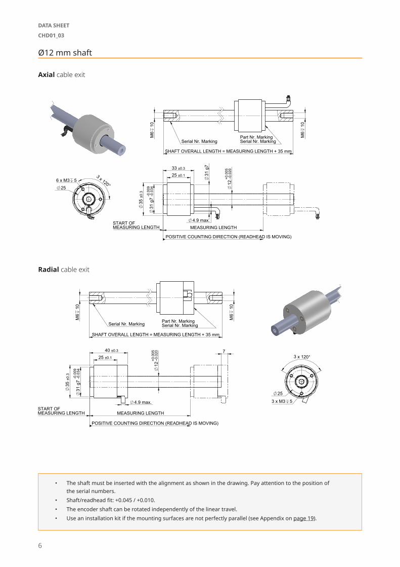
Ø12 mm shaft
Axial cable exit
Radial cable exit
• The shaft must be inserted with the alignment as shown in the drawing. Pay attention to the position of the serial numbers.
• Shaft/readhead fit: +0.045 / +0.010.• The encoder shaft can be rotated independently of the linear travel.• Use an installation kit if the mounting surfaces are not perfectly parallel (see Appendix on page 19).
31
g7
- -0.00
90.
034
35
±0.
3
4.9 max.
31
g7
25 ±0.1 33 ±0.3
12
MEASURING LENGTH
POSITIVE COUNTING DIRECTION (READHEAD IS MOVING)
START OF MEASURING LENGTH
M6
10
M6
10
SHAFT OVERALL LENGTH = MEASURING LENGTH + 35 mm
Part Nr. MarkingSerial Nr. Marking Serial Nr. Marking
3 x 120° 25 6 x M3 5
CH12-A
-
00CH12-AD01
-
-
+0.0
05–0
.020
7
31
g7
- -0.00
90.
034
35
±0.
3
25 ±0.1 40 ±0.3
12
4.9 max.
MEASURING LENGTH
POSITIVE COUNTING DIRECTION (READHEAD IS MOVING)
START OF MEASURING LENGTH
M6
10
M6
10
SHAFT OVERALL LENGTH = MEASURING LENGTH + 35 mm
Serial Nr. Marking Part Nr. MarkingSerial Nr. Marking
3 x M3 5
3 x 120°
25
CH12-B
-
00CH12-BD01
-
-
+0.0
05–0
.020
6
DATA SHEET
CHD01_03
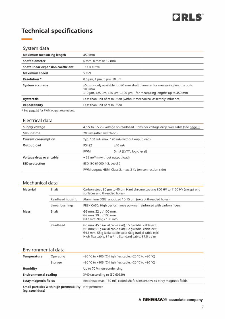
Technical specifications
System dataMaximum measuring length 450 mm
Shaft diameter 6 mm, 8 mm or 12 mm
Shaft linear expansion coefficient ~11 × 10-6/K
Maximum speed 5 m/s
Resolution * 0.5 µm, 1 µm, 5 µm, 10 µm
System accuracy ±5 μm – only available for Ø6 mm shaft diameter for measuring lengths up to 100 mm±10 μm, ±25 μm, ±50 μm, ±100 µm – for measuring lengths up to 450 mm
Hysteresis Less than unit of resolution (without mechanical assembly influence)
Repeatability Less than unit of resolution
Electrical dataSupply voltage 4.5 V to 5.5 V – voltage on readhead. Consider voltage drop over cable (see page 8).
Set-up time 200 ms (after switch-on)
Current consumption Typ. 100 mA, max. 120 mA (without ouput load)
Output load RS422 ±40 mA
PWM 5 mA (LVTTL logic level)
Voltage drop over cable ~ 55 mV/m (without output load)
ESD protection ESD IEC 61000-4-2, Level 2
PWM output: HBM, Class 2, max. 2 kV (on connection side)
Mechanical dataMaterial Shaft Carbon steel, 30 µm to 40 µm Hard chrome coating 800 HV to 1100 HV (except end
surfaces and threaded holes)
Readhead housing Aluminium 6082; anodized 10-15 µm (except threaded holes)
Linear bushings PEEK CA30; High performance polymer reinforced with carbon fibers
Mass Shaft Ø6 mm: 22 g / 100 mm; Ø8 mm: 39 g / 100 mm; Ø12 mm: 90 g / 100 mm
Readhead Ø6 mm: 45 g (axial cable exit), 55 g (radial cable exit)Ø8 mm: 51 g (axial cable exit), 62 g (radial cable exit)Ø12 mm: 55 g (axial cable exit), 66 g (radial cable exit)High flex cable: 34 g / m; Standard cable: 37.5 g / m
Environmental dataTemperature Operating –30 °C to +105 °C (high flex cable: –20 °C to +80 °C)
Storage –30 °C to +105 °C (high flex cable: –20 °C to +80 °C)
Humidity Up to 70 % non-condensing
Environmental sealing IP40 (according to IEC 60529)
Stray magnetic fields Readhead max. 150 mT, coded shaft is insensitive to stray magnetic fields
Small particles with high permeability (eg. steel dust)
Not permitted
* See page 10 for PWM output resolutions.
7
®
A associate company
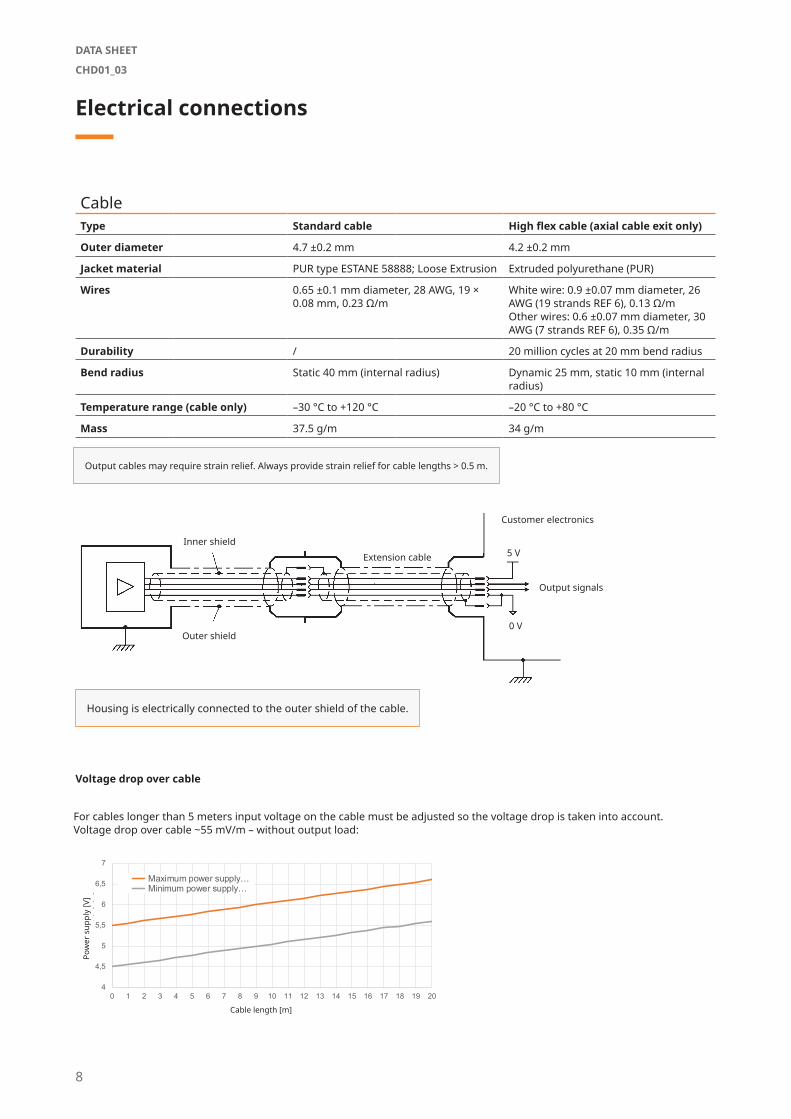
Electrical connections
Voltage drop over cable
Output cables may require strain relief. Always provide strain relief for cable lengths > 0.5 m.
Inner shield
Outer shield
Extension cable
Customer electronics
Output signals
5 V
0 V
Housing is electrically connected to the outer shield of the cable.
CableType Standard cable High flex cable (axial cable exit only)
Outer diameter 4.7 ±0.2 mm 4.2 ±0.2 mm
Jacket material PUR type ESTANE 58888; Loose Extrusion Extruded polyurethane (PUR)
Wires 0.65 ±0.1 mm diameter, 28 AWG, 19 × 0.08 mm, 0.23 Ω/m
White wire: 0.9 ±0.07 mm diameter, 26 AWG (19 strands REF 6), 0.13 Ω/mOther wires: 0.6 ±0.07 mm diameter, 30 AWG (7 strands REF 6), 0.35 Ω/m
Durability / 20 million cycles at 20 mm bend radius
Bend radius Static 40 mm (internal radius) Dynamic 25 mm, static 10 mm (internal radius)
Temperature range (cable only) –30 °C to +120 °C –20 °C to +80 °C
Mass 37.5 g/m 34 g/m
For cables longer than 5 meters input voltage on the cable must be adjusted so the voltage drop is taken into account. Voltage drop over cable ~55 mV/m – without output load:
Pow
er s
uppl
y [V
]
Cable length [m]
4
4,5
5
5,5
6
6,5
7
0 1 2 3 4 5 6 7 8 9 10 11 12 13 14 15 16 17 18 19 20
Pow
er s
uppl
y [V
]
Cable length [m]
Voltage drop over cable
Maximum power supply… Minimum power supply…
8
DATA SHEET
CHD01_03
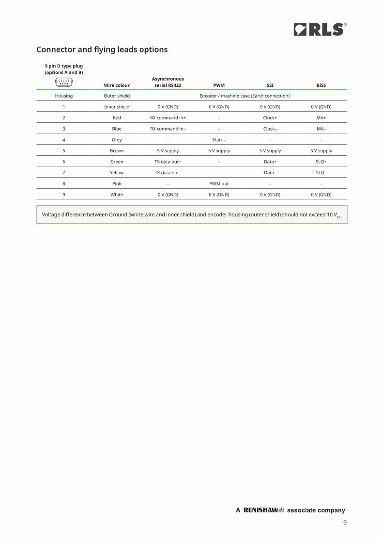
Connector and flying leads options
9 pin D type plug (options A and B)
Wire colourAsynchronous
serial RS422 PWM SSI BiSS
Housing Outer shield Encoder / machine case (Earth connection)
1 Inner shield 0 V (GND) 0 V (GND) 0 V (GND) 0 V (GND)
2 Red RX command in+ – Clock+ MA+
3 Blue RX command in– – Clock– MA–
4 Grey – Status – –
5 Brown 5 V supply 5 V supply 5 V supply 5 V supply
6 Green TX data out+ – Data+ SLO+
7 Yellow TX data out– – Data– SLO–
8 Pink – PWM out – –
9 White 0 V (GND) 0 V (GND) 0 V (GND) 0 V (GND)
Voltage difference between Ground (white wire and inner shield) and encoder housing (outer shield) should not exceed 10 Vpp.
9
®
A associate company
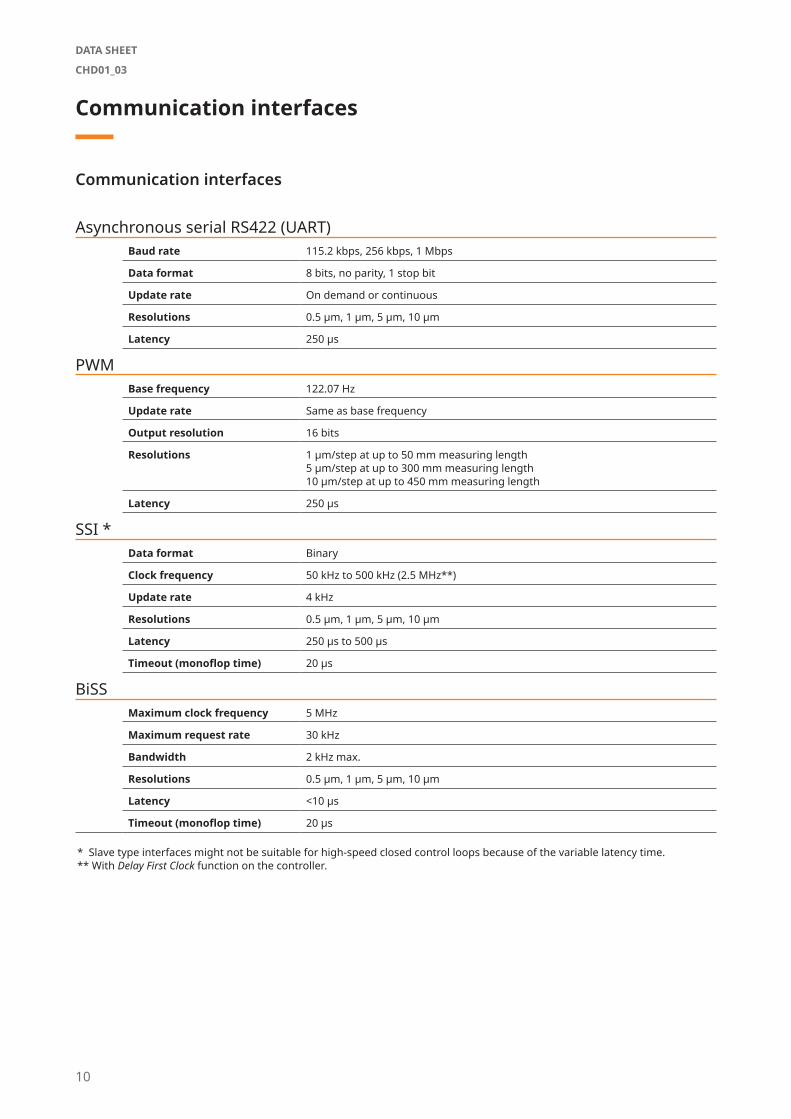
Communication interfaces
Communication interfaces
Asynchronous serial RS422 (UART)Baud rate 115.2 kbps, 256 kbps, 1 Mbps
Data format 8 bits, no parity, 1 stop bit
Update rate On demand or continuous
Resolutions 0.5 µm, 1 µm, 5 µm, 10 µm
Latency 250 µs
PWMBase frequency 122.07 Hz
Update rate Same as base frequency
Output resolution 16 bits
Resolutions 1 µm/step at up to 50 mm measuring length5 µm/step at up to 300 mm measuring length10 µm/step at up to 450 mm measuring length
Latency 250 µs
SSI *Data format Binary
Clock frequency 50 kHz to 500 kHz (2.5 MHz**)
Update rate 4 kHz
Resolutions 0.5 µm, 1 µm, 5 µm, 10 µm
Latency 250 µs to 500 µs
Timeout (monoflop time) 20 µs
BiSSMaximum clock frequency 5 MHz
Maximum request rate 30 kHz
Bandwidth 2 kHz max.
Resolutions 0.5 µm, 1 µm, 5 µm, 10 µm
Latency <10 µs
Timeout (monoflop time) 20 µs
* Slave type interfaces might not be suitable for high-speed closed control loops because of the variable latency time.** With Delay First Clock function on the controller.
10
DATA SHEET
CHD01_03
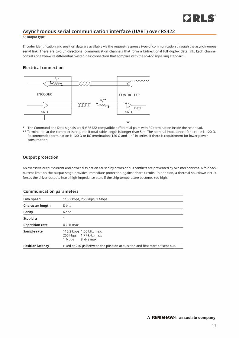
Asynchronous serial communication interface (UART) over RS422SF output type
Encoder identification and position data are available via the request-response type of communication through the asynchronous serial link. There are two unidirectional communication channels that form a bidirectional full duplex data link. Each channel consists of a two-wire differential twisted-pair connection that complies with the RS422 signalling standard.
Electrical connection
p
era
ng
rcu
Rt**
VCC VCC Command
Data
CONTROLLERENCODER
GND GND
Rt*
* The Command and Data signals are 5 V RS422 compatible differential pairs with RC termination inside the readhead.** Termination at the controller is required if total cable length is longer than 5 m. The nominal impedance of the cable is 120 Ω.
Recommended termination is 120 Ω or RC termination (120 Ω and 1 nF in series) if there is requirement for lower power consumption.
Output protection
An excessive output current and power dissipation caused by errors or bus conflicts are prevented by two mechanisms. A foldback current limit on the output stage provides immediate protection against short circuits. In addition, a thermal shutdown circuit forces the driver outputs into a high-impedance state if the chip temperature becomes too high.
Communication parameters
Link speed 115.2 kbps, 256 kbps, 1 Mbps
Character length 8 bits
Parity None
Stop bits 1
Repetition rate 4 kHz max.
Sample rate 115.2 kbps 1.05 kHz max.256 kbps 1.77 kHz max.1 Mbps 3 kHz max.
Position latency Fixed at 250 µs between the position acquisition and first start bit sent out.
11
®
A associate company

Encoder status (two bytes):
b15 : b10 Reserved; always zero
General status
b9 Error bit. If set, the position is not valid.
b8 Warning bit. If set, the encoder operational is close to its limits. The position is still valid, but the resolution and / or accuracy
might be lower than specified.
Error and Warning bits can be set at the same time; in this case Error bit has priority.
The general warning or error status is more closely defined by the Detailed status bits.
Detailed status
b7 Warning - Signal amplitude too high. The readhead is too close to the shaft.
b6 Warning - Signal amplitude low. The distance between the readhead and the shaft is too large.
b5 Error - Signal lost. The readhead is too far away from the shaft.
b4 Warning - Temperature. The readhead temperature is out of specified range.
b3 Error - Power supply error. The readhead power supply voltage out of specified range.
b2 Error - System error. Malfunction inside the circuitry or inconsistent calibration data is detected. To reset the System error bit try to
cycle the power supply while the rise time is shorter than 20 ms.
b1 Error - Wrong code. Shaft might be inserted in the wrong direction.
b0 Error - Acceleration error. The position data changed too fast. Shaft might be inserted in the wrong direction.
Command “v” (small character “v”)
Response - version info and serial number 8 bytes ASCII Serial number 1 byte binary Firmware version (42) 1 byte binary ASIC revision (31) 1 byte binary Resolution (factor 0.1 µm) 6 bytes ASCII code description
Command “1” (ASCII one)
Response - position and status, transmitted once 1 byte constant header 0xEA 4 bytes binary absolute position, big-endian, right aligned 2 bytes encoder status – see table on next page 1 byte constant footer 0xEF
The next request should not be sent sooner than 250 µs after the end of the previous response from the readhead to allow re-freshing of the position data. If request is sent sooner, data will arrive on the end of the refresh cycle.
Command “2” (ASCII two)
Response - position and status, transmitted continuously every cycle (250 µs + time of transmission depandant on baud rate) 1 byte constant header 0xEA 4 bytes binary absolute position, big-endian, right aligned 2 bytes encoder status – see table on next page 1 byte constant footer 0xEF
Command “0” (ASCII zero)
Stop continuous transmission
Command set
Structure of Detailed status bits (two bytes)
12
DATA SHEET
CHD01_03
0.125 µs 8192 µs
8191.875 µs
Zero position
Maximum position
PWmin
PWmax
1/fPWM
Communication parametersCommunication interface variant in the part number defines the PWM frequency and all other dependent parameters.
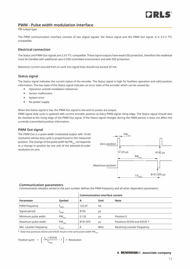
Position [µm] = – 1 × Resolution)( ton × 65536TPWM
PWM - Pulse width modulation interfacePW output type
The PWM communication interface consists of two digital signals: the Status signal and the PWM Out signal. It is 3.3 V TTL compatible.
Electrical connectionThe Status and PWM Out signals are 3.3 V TTL compatible. These signal outputs have weak ESD protection, therefore the readhead must be handled with additional care in ESD controlled environment and with ESD protection. Maximum current sourced from or sunk into signal lines should not exceed 20 mA.
Status signalThe Status signal indicates the current status of the encoder. The Status signal is high for faultless operation and valid position information. The low state of the Status signal indicates an error state of the encoder which can be caused by:
⦁ Operation outside installation tolerances ⦁ Sensor malfunction ⦁ System error ⦁ No power supply
When the Status signal is low, the PWM Out signal is low and no pulses are output.PWM signal duty cycle is updated with current encoder position at every PWM signal rising edge. The Status signal should also be checked at the rising edge of the PWM Out signal. If the Status signal changes during the PWM period, it does not affect the currently transmitted position information.
PWM Out signalThe PWM Out is a pulse width modulated output with 16-bit resolution whose duty cycle is proportional to the measured position. The change of the pulse width by PWmin corresponds to a change in position by one unit of the selected encoder resolution (in µm).
Communication interface variant
Parameter Symbol A Unit Note
PWM frequency fPWM 122.07 Hz
Signal period tPWM 8192 μs
Minimum pulse width PWmin 0.125 μs Position 0
Maximum pulse width PWmax 8191.875 μs Positions 65534 and 65535 *
Min. counter frequency fCNTR 8 MHz Receiving counter frequency* Note that positions 65534 and 65535 result in the same pulse width PWmax.
13
®
A associate company

SSI - Synchronous serial interfaceSC output type
The encoder position, in 21 bit natural binary code, and the encoder status are available through the SSI protocol. The position data is right aligned. LSB represents selected encoder resolution. After the position data there are two general status bits followed by the detailed status information.
p
era
ng
rcu
Rt**
Vin
Rb***
Rb***VCC VCC Clock
Data
CONTROLLERENCODER
GND GND
Rt*
* The Clock and Data signals are 5 V RS422 compatible differential pairs with RC termination inside the readhead.** Termination at the controller is required, if total cable length is longer than 5 m. The nominal impedance of the cable is
120 Ω. Recommended termination is 120 Ω or RC termination (120 Ω and 1 nF in series) if there is requirement for lower power consumption.
*** Clock should have a defined state during encoder start up. Recommended value for Rb is 1 kΩ.
The power supply must be applied at least 200 ms before the clock sequence is being sent to the encoder.
Output protection
An excessive output current and power dissipation caused by errors or bus conflicts are prevented by two mechanisms. A foldback current limit on the output stage provides immediate protection against short circuits. In addition, a thermal shutdown circuit forces the driver outputs into a high-impedance state, if the chip temperature becomes too high.
Timing diagram
The controller queries the readhead for its position and status data by sending a pulse train to the Clock input. The Clock signal always starts from High. The first falling edge ① latches the last available position data, and on the first rising edge ② the most significant bit (MSB) of the position is transmitted to the Data output. The Data output should then be latched on the following falling edge. On the subsequent rising edges of the Clock signal, the next bits are transmitted. If the time between ① and ② is extended for additional 1 µs, the maximum clock frequency limit is 2.5 MHz instead of 500 kHz. This function is called “Delay First Clock” and must be supported by the controller to which the encoder is connected.
After transmission of the last bit ③ the Data output goes to low. When the time tM has expired, the Data output is undefined ④. The Clock signal must remain high at least for tM before the next reading can take place.
When reading the data, the period tCL must always be less than tM. However, reading the encoder position can be stopped at any time by setting the Clock signal to high for the duration of tM.
In order for the position data to be updated, at least tB should elapse between two successive readings. If the read request arrives earlier than tB after the previous read, the encoder position is not updated.
tCL1 2 3
tM
4
b30 b29 b28 b2b3 b1 b0
Clock
DataMSB LSBStart Idle
tB
Electrical connection
14
DATA SHEET
CHD01_03

Maximum frequency
The readhead needs 170 ns to respond to incoming clocks (tRESP). Change on Data signal is delayed for 170 ns after the rising edge on Clock line. An additional delay is caused by the time it takes for the signal needs to propagate through the cable to the readhead and back (tPROP). This delay is typically 14 ns per 1 meter cable. The Data signal must be stable over at least 10% of the length of the clock period before the value is latched. The clock frequency must be reduced with a longer cable. The total cable length from the encoder to the receiver must be considered.
Frequency derating versus cable length:
tDELAY = tRESP + tPROP x cable length
Cable length [m]
1,0
0 10 20 30 40 50 60 70 80 90 1000
0.5
1
1.5
2.5
2
3
Max
imum
freq
uenc
y [M
Hz]
Clock
Data
tSTABLEtRESP
Parameter Symbol Min Typ Max
Delay first clock tDFC 1 µs 10 µs
Clock period tCL 2 µs 20 µs
Clock frequency fCL 50 kHz 500 kHz (2.5 MHz *)
Timeout (Monoflop time) tM 20 µs
Update time tB 250 µs
Readhead response delay tRESP 170 ns
Cable propagation delay tPROP 14 ns/m
Latency 250 µs 500 µs
Communication parameters
* With Delay First Clock function on the controller.
Bit b30 : b10 b9 : b8 b7 : b0
Data length 21 bits 2 bits 8 bits
Meaning Encoder position General status Detailed status
Structure of data packet
Start bit and idle line value are defined by the Communication interface variant.
Communication interface variant Line state selection Usage
B Start bit = 1; idle line = 1 Standard
15
®
A associate company

Encoder position
b30 : b10 Encoder position – Right aligned, MSB
General status
b9 Error bit. If set, the position is not valid.
b8 Warning bit. If set, the encoder operational is close to its limits. The position is still valid, but the resolution and/or accu-
racy might be out of specification.
The Error and Warning bits can be set at the same time, in this case the Error bit has priority.
The general warning or error status is more closely defined by the Detailed status bits.
Detailed status
b7 Warning - Signal amplitude too high. The readhead is too close to the shaft.
b6 Warning - Signal amplitude low. The distance between the readhead and the shaft is too large.
b5 Error - Signal lost. The readhead is too far away from the shaft.
b4 Warning - Temperature. The readhead temperature is out of specified range.
b3 Error - Power supply error. The readhead power supply voltage out of specified range.
b2 Error - System error. Malfunction inside the circuitry or inconsistent calibration data is detected. To reset the System
error bit try to cycle the power supply while the rise time is shorter than 20 ms.
b1 Error - Wrong code. Shaft might be inserted in the wrong direction.
b0 Error - Acceleration error. The position data changed too fast. Shaft might be inserted in the wrong direction.
Structure of data packet
16
DATA SHEET
CHD01_03
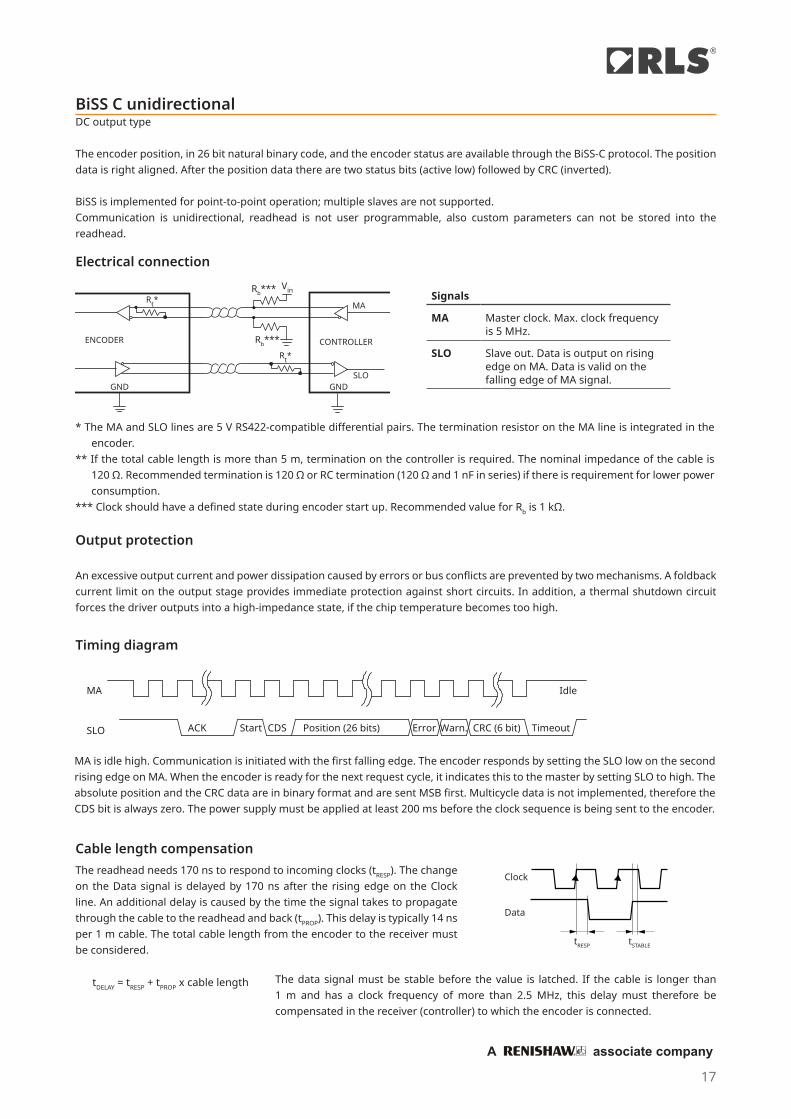
BiSS C unidirectionalDC output type
The encoder position, in 26 bit natural binary code, and the encoder status are available through the BiSS-C protocol. The position data is right aligned. After the position data there are two status bits (active low) followed by CRC (inverted).
BiSS is implemented for point-to-point operation; multiple slaves are not supported.Communication is unidirectional, readhead is not user programmable, also custom parameters can not be stored into the readhead.
pe
rang
rc
u
Rt*
F
VCCRO
H/F
DE
DI
0.1 F
VCCI
E/
O
MA
CONTROLLERENCODER
GND GNDSLO
Rt*
Rb***
F
VinRb***
Electrical connection
* The MA and SLO lines are 5 V RS422-compatible differential pairs. The termination resistor on the MA line is integrated in the encoder.
** If the total cable length is more than 5 m, termination on the controller is required. The nominal impedance of the cable is 120 Ω. Recommended termination is 120 Ω or RC termination (120 Ω and 1 nF in series) if there is requirement for lower power consumption.
*** Clock should have a defined state during encoder start up. Recommended value for Rb is 1 kΩ.
Output protection
An excessive output current and power dissipation caused by errors or bus conflicts are prevented by two mechanisms. A foldback current limit on the output stage provides immediate protection against short circuits. In addition, a thermal shutdown circuit forces the driver outputs into a high-impedance state, if the chip temperature becomes too high.
CDS ErrorPosition (26 bits) Warn. CRC (6 bit)
MA
SLO ACK TimeoutStart
Idle
MA is idle high. Communication is initiated with the first falling edge. The encoder responds by setting the SLO low on the second rising edge on MA. When the encoder is ready for the next request cycle, it indicates this to the master by setting SLO to high. The absolute position and the CRC data are in binary format and are sent MSB first. Multicycle data is not implemented, therefore the CDS bit is always zero. The power supply must be applied at least 200 ms before the clock sequence is being sent to the encoder.
tDELAY = tRESP + tPROP x cable length
Clock
Data
tRESP tSTABLE
Timing diagram
Signals
MA Master clock. Max. clock frequency is 5 MHz.
SLO Slave out. Data is output on rising edge on MA. Data is valid on the falling edge of MA signal.
The readhead needs 170 ns to respond to incoming clocks (tRESP). The change on the Data signal is delayed by 170 ns after the rising edge on the Clock line. An additional delay is caused by the time the signal takes to propagate through the cable to the readhead and back (tPROP). This delay is typically 14 ns per 1 m cable. The total cable length from the encoder to the receiver must be considered.
The data signal must be stable before the value is latched. If the cable is longer than 1 m and has a clock frequency of more than 2.5 MHz, this delay must therefore be compensated in the receiver (controller) to which the encoder is connected.
Cable length compensation
17
®
A associate company
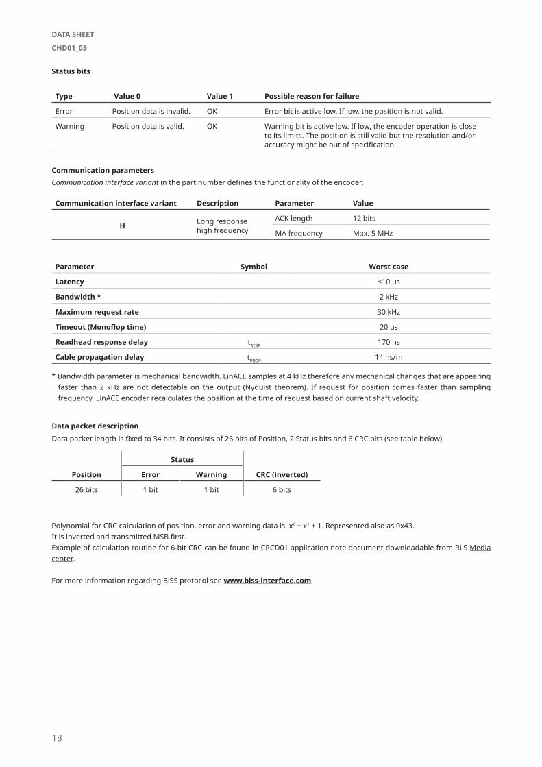
Type Value 0 Value 1 Possible reason for failure
Error Position data is invalid. OK Error bit is active low. If low, the position is not valid.
Warning Position data is valid. OK Warning bit is active low. If low, the encoder operation is close to its limits. The position is still valid but the resolution and/or accuracy might be out of specification.
Status bits
Communication parametersCommunication interface variant in the part number defines the functionality of the encoder.
Data packet description
Position
Status
CRC (inverted)Error Warning
26 bits 1 bit 1 bit 6 bits
Polynomial for CRC calculation of position, error and warning data is: x6 + x1 + 1. Represented also as 0x43.It is inverted and transmitted MSB first.Example of calculation routine for 6-bit CRC can be found in CRCD01 application note document downloadable from RLS Media center.
For more information regarding BiSS protocol see www.biss-interface.com.
Data packet length is fixed to 34 bits. It consists of 26 bits of Position, 2 Status bits and 6 CRC bits (see table below).
Communication interface variant Description Parameter Value
H Long response high frequency
ACK length 12 bits
MA frequency Max. 5 MHz
Parameter Symbol Worst case
Latency <10 µs
Bandwidth * 2 kHz
Maximum request rate 30 kHz
Timeout (Monoflop time) 20 µs
Readhead response delay tRESP 170 ns
Cable propagation delay tPROP 14 ns/m
* Bandwidth parameter is mechanical bandwidth. LinACE samples at 4 kHz therefore any mechanical changes that are appearing faster than 2 kHz are not detectable on the output (Nyquist theorem). If request for position comes faster than sampling frequency, LinACE encoder recalculates the position at the time of request based on current shaft velocity.
18
DATA SHEET
CHD01_03
Exploded view:
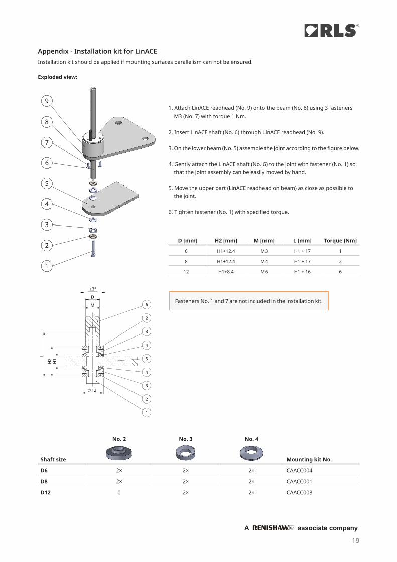
Appendix - Installation kit for LinACEInstallation kit should be applied if mounting surfaces parallelism can not be ensured.
8
7
6
5
4
3
2
1
91. Attach LinACE readhead (No. 9) onto the beam (No. 8) using 3 fasteners M3 (No. 7) with torque 1 Nm.
2. Insert LinACE shaft (No. 6) through LinACE readhead (No. 9).
3. On the lower beam (No. 5) assemble the joint according to the figure below.
4. Gently attach the LinACE shaft (No. 6) to the joint with fastener (No. 1) so that the joint assembly can be easily moved by hand.
5. Move the upper part (LinACE readhead on beam) as close as possible to the joint.
6. Tighten fastener (No. 1) with specified torque.
H2
H1
12
L
D
M
±3°
1
2
3
4
5
4
3
2
6
D [mm] H2 [mm] M [mm] L [mm] Torque [Nm]
6 H1+12.4 M3 H1 + 17 1
8 H1+12.4 M4 H1 + 17 2
12 H1+8.4 M6 H1 + 16 6
Fasteners No. 1 and 7 are not included in the installation kit.
Shaft size
No. 2 No. 3 No. 4
Mounting kit No.
D6 2× 2× 2× CAACC004
D8 2× 2× 2× CAACC001
D12 0 2× 2× CAACC003
19
®
A associate company
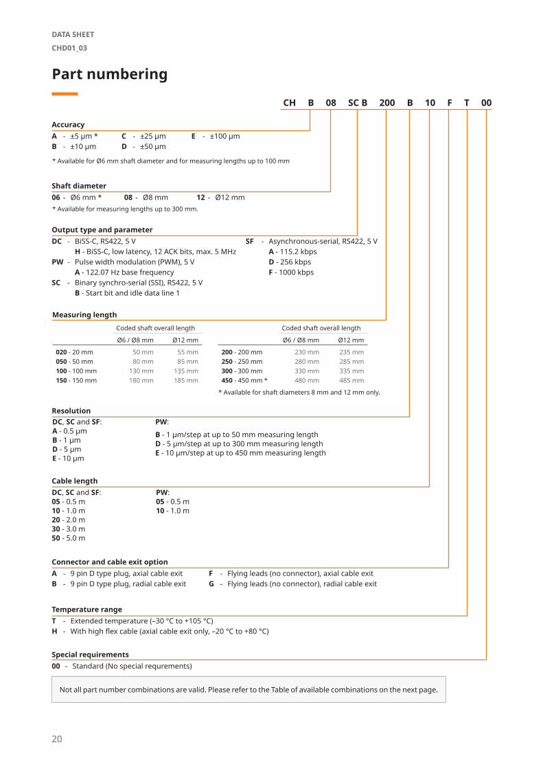
Part numbering
CH B 08 SC B 200 B 10 F T 00
Connector and cable exit optionA - 9 pin D type plug, axial cable exitB - 9 pin D type plug, radial cable exit
Not all part number combinations are valid. Please refer to the Table of available combinations on the next page.
AccuracyA - ±5 μm *B - ±10 μm
C - ±25 μmD - ±50 μm
E - ±100 μm
Shaft diameter06 - Ø6 mm * 12 - Ø12 mm08 - Ø8 mm
Output type and parameterDC - BiSS-C, RS422, 5 V
H - BiSS-C, low latency, 12 ACK bits, max. 5 MHzPW - Pulse width modulation (PWM), 5 V
A - 122.07 Hz base frequencySC - Binary synchro-serial (SSI), RS422, 5 V
B - Start bit and idle data line 1
F - Flying leads (no connector), axial cable exitG - Flying leads (no connector), radial cable exit
Measuring length
Cable length
Special requirements00 - Standard (No special requrements)
Temperature rangeT - Extended temperature (–30 °C to +105 °C)H - With high flex cable (axial cable exit only, –20 °C to +80 °C)
ResolutionPW:B - 1 µm/step at up to 50 mm measuring lengthD - 5 μm/step at up to 300 mm measuring lengthE - 10 μm/step at up to 450 mm measuring length
* Available for Ø6 mm shaft diameter and for measuring lengths up to 100 mm
* Available for measuring lengths up to 300 mm.
SF - Asynchronous-serial, RS422, 5 VA - 115.2 kbpsD - 256 kbpsF - 1000 kbps
Coded shaft overall length
Ø6 / Ø8 mm Ø12 mm
020 - 20 mm 50 mm 55 mm050 - 50 mm 80 mm 85 mm100 - 100 mm 130 mm 135 mm150 - 150 mm 180 mm 185 mm
* Available for shaft diameters 8 mm and 12 mm only.
Coded shaft overall length
Ø6 / Ø8 mm Ø12 mm
200 - 200 mm 230 mm 235 mm250 - 250 mm 280 mm 285 mm300 - 300 mm 330 mm 335 mm450 - 450 mm * 480 mm 485 mm
DC, SC and SF:05 - 0.5 m10 - 1.0 m20 - 2.0 m30 - 3.0 m50 - 5.0 m
PW:05 - 0.5 m10 - 1.0 m
DC, SC and SF:A - 0.5 μmB - 1 μmD - 5 μmE - 10 μm
20
DATA SHEET
CHD01_03

Series AccuracyShaft
diameterOutput
typeOutput type parameter Measuring length
Reso-lution
Cable length
Connec-tor
Temper-ature range
Special require-ments
CH
A 06
PW A 020 / 050 B 05 / 10
A / B / F / G
T / H* 00
DC H
020 / 050 / 100 A / B05 / 10 / 20
/ 30 / 50SC B
SF A / D / F
B
06
PW A 020 / 050 B 05 / 10
DC H020 / 050 / 100 / 150
/ 200 / 250 / 300A / B
05 / 10 / 20 / 30 / 50SC B
SF A / D / F
08 / 12
PW A 020 / 050 B 05 / 10
DC H020 / 050 / 100 / 150
/ 200 / 250 / 300 / 450
A / B05 / 10 / 20
/ 30 / 50SC B
SF A / D / F
C
06
PW A020 / 050 B
05 / 10
020 / 050 / 100 / 150 / 200 / 250 / 300
D
DC HA / B / D
05 / 10 / 20 / 30 / 50
SC B
SF A / D / F
08 / 12
PW A
020 / 050 B
05 / 10020 / 050 / 100 / 150 / 200 / 250 / 300
D
DC H020 / 050 / 100 / 150
/ 200 / 250 / 300 / 450
A / B / D
05 / 10 / 20 / 30 / 50
SC B
SF A / D / F
D / E
06
PW A
020 / 050 B
05 / 10020 / 050 / 100 / 150 / 200 / 250 / 300
D / E
DC H020 / 050 / 100 / 150
/ 200 / 250 / 300A / B / D / E
05 / 10 / 20 / 30 / 50
SC B
SF A / D / F
08 / 12
PW A
020 / 050 B
05 / 10020 / 050 / 100 / 150
/ 200 / 250 / 300D
020 / 050 / 100 / 150 / 200 / 250 / 300
/ 450
E
DC HA / B / D / E
05 / 10 / 20 / 30 / 50
SC B
SF A / D / F
Table of available combinations
* Available for axial cable exit only.
21
®
A associate company
A associate company
®
RLS merilna tehnika d.o.o.
Poslovna cona Žeje pri KomendiPod vrbami 2SI-1218 KomendaSlovenia
Head office
Global support
T +386 1 5272100F +386 1 5272129E [email protected]
RLS Merilna tehnika d.o.o. has made considerable effort to ensure the content of this document is correct at the date of publication but makes no warranties or representa-tions regarding the content. RLS Merilna tehnika d.o.o. excludes liability, howsoever arising, for any inaccuracies in this document. © 2020 RLS d.o.o.
This product is not designed or intended for use outside the environmental limitations and operating parameters expressly stated on the product’s datasheet. Products are not designed or intended for use in medical, military, aerospace, automotive or oil & gas applications or any safety-critical applications where a failure of the product could cause severe environmental or property damage, personal injury or death. Any use in such applications must be specifically agreed to by seller in writing, and is subject to such additional terms as the seller may impose in its sole discretion. Use of products in such applications is at buyer’s own risk, and buyer will indemnify and hold harmless seller and its affiliates against any liability, loss, damage or expense arising from such use. Information contained in this datasheet was derived from product testing under controlled laboratory conditions and data reported thereon is subject to the stated tolerances and variations, or if none are stated, then to tolerances and variations consist-ent with usual trade practices and testing methods. The product’s performance outside of laboratory conditions, including when one or more operating parameters is at its maximum range, may not conform to the product’s datasheet. Further, information in the product’s datasheet does not reflect the performance of the product in any appli-cation, end-use or operating environment buyer or its customer may put the product to. Seller and its affiliates make no recommendation, warranty or representation as to the suitability of the product for buyer’s application, use, end-product, process or combination with any other product or as to any results buyer or its customer might obtain in their use of the product. Buyer should use its own knowledge, judgment, expertise and testing in selecting the product for buyer’s application, end-use and/or operating environment, and should not rely on any oral or written statement, representation, or samples made by seller or its affiliates for any purpose. EXCEPT FOR THE WARRANTIES EXPRESSLY SET FORTH IN THE SELLER’S TERMS AND CONDITIONS OF SALE, SELLER MAKES NO WARRANTY EXPRESS OR IMPLIED WITH RESPECT TO THE PRODUCT, INCLUDING ANY WARRANTY OF MERCHANTABILITY OR FITNESS FOR ANY PARTICULAR PURPOSE, WHICH ARE DISCLAIMED AND EXCLUDED. All sales are subject to seller’s exclusive terms and conditions of sale which, where the seller is (a) RLS Merilna tehnika d.o.o., are available at https://www.rls.si/eng/salesterms, (b) Renishaw, Inc., are available at https://www.renishaw.com/legal/en/--42186, or (c) another person, are available on request, and in each case, are incorporated herein by reference, and are the exclusive terms of sale. No other terms and conditions apply. Buyer is not authorized to make any statements or representations that expand upon or extend the environmental limitations and operating parameters of the products, or which imply permitted usage outside of that expressly stated on the datasheet or agreed to in writing by seller.
www.rls.si
Contact your nearest sales representative