Embed Size (px)
Citation preview
Combined CyclePower Plants
Combined CyclePower Plant Overview(Single- and Multi-Shaft)
Training Module
ALSTOM (Switzerland) Ltd ����
Combined Cycle CCPP OverviewPower Plants (Single- and Multi-Shaft)
———————————————— Power Plant Training Center ————————————————CSXA220021enC Page 2
����
We reserve all rights in this document and in the information contained therein. Reproduc-tion, use or disclosure to third parties without express authority is strictly forbidden.Copyright� by ALSTOM (Switzerland) Ltd 2004
This is a training module.All mentioned / attached values and settings are for information only. The values might bechanged during commissioning.For actual values please refer to the Instruction Manual.
Combined Cycle CCPP OverviewPower Plants (Single- and Multi-Shaft)
———————————————— Power Plant Training Center ————————————————CSXA220021enC Page 3
����
Table of Contents
List of Technical Aids ............................................................................................................................................. 4
Module Objectives .................................................................................................................................................. 5
Overview................................................................................................................................................................... 6
Gas Turbine Power Plant Overview...................................................................................................................... 6Gas Turbine Main Components and Functional Principle .................................................................................. 7Generator Components and Functional Principle ............................................................................................... 8
Steam Turbine Power Plant Overview................................................................................................................ 10Basic Components of a Steam Turbine Power Plant........................................................................................ 10
Combined Cycle Power Plant Overview............................................................................................................. 11Multi-Shaft Arrangement.................................................................................................................................... 11Single-Shaft Arrangement ................................................................................................................................. 12
Overview of a Combined Cycle Plant for CHE Supply ..................................................................................... 13Multi-Shaft Arrangement.................................................................................................................................... 13
Overview of a Combined Cycle Plant for CHE Supply ..................................................................................... 14Single-Shaft Arrangement ................................................................................................................................. 14
Control and Protection System Overview.......................................................................................................... 15
Summary ................................................................................................................................................................ 18
Figure 1: Simplified Overview of a Gas Turbine Power Plant, its Major Components and Systems......... 19
Figure 2: Simplified Overview of Steam Turbine Power Plant, its Major Components and Systems....... 20
Figure 3.1: Combined Cycle Power Plant Process Overview (Multi- Shaft) .................................................. 21
Figure 3.2: Combined Cycle Power Plant Process Overview (Single- Shaft)................................................ 22
Figure 3.3: Combined Cycle Plant for CHE Supply and Multi-Shaft Arrangement ....................................... 23
Figure 3.4: Combined Cycle Plant for CHE Supply and Single-Shaft Arrangement..................................... 24
Figure 3.5: CHE Supply Plant .............................................................................................................................. 25
Figure 4: Basic Scheme of the Control of a Combined Cycle Power Plant................................................... 26
Figure 5: Simplified Water Steam Cycle............................................................................................................. 27
Combined Cycle CCPP OverviewPower Plants (Single- and Multi-Shaft)
———————————————— Power Plant Training Center ————————————————CSXA220021enC Page 4
����
List of Technical Aids
Definitions Enclosure Integral Standard DocumentAttachment Attached Site-Specific Illustration or Document
Identification Description
Attachment 1 Plant Operation and Control Concept
Combined Cycle CCPP OverviewPower Plants (Single- and Multi-Shaft)
———————————————— Power Plant Training Center ————————————————CSXA220021enC Page 5
����
Module Objectives
Upon completion of this section, the trainee is able to:
� State why combined cycle power plants are used in preference for supplying electricenergy.
� Explain why a gas turbine set includes:� A turbine� A combustion chamber� A compressor
� Give the reasons why the main electrical energy supply chain contains:� A generator� An exciter� Generator bushings� A generator breaker� A main step-up transformer� A grid breaker
� Justify the use of a boiler and a steam turbine within a steam turbine power plant.
� Explain the reasons why the following components are used within a combined cyclepower plant:� Heat recovery steam boiler� Condenser� Deaerator and feed water storage tank
� Justify the use of a combined cycle plant as a process for combined heat and electricity(CHE) supply.
� State the reasons why a combined cycle power plant includes in its automation system thefollowing components:� Gas turbine electronic controller (EGATROL)� Steam turbine electronic controller (TURBOTROL)� Steam Turbine generator set sequencer (TURBOMAT)� Voltage regulator (UNITROL)� Synchronizer (SYNCHROTACT)� Generator protection (GSX or REG)� Heat recovery steam boiler controller (BOILERMAT)
Combined Cycle CCPP OverviewPower Plants (Single- and Multi-Shaft)
———————————————— Power Plant Training Center ————————————————CSXA220021enC Page 6
����
Overview
CCPP as energysupplier
A relative newcomer to the field of energy supply is the combined cycle power plant(CCPP).� CCPPs take the advantages of gas turbosets and steam turbosets and combine them in a
system that provides electric power at a much higher efficiency than is possible witheither system operating alone.
This section will briefly describe the process of typical ALSTOM gas and steam turbinepower plants before summarizing how those processes are combined in a typical CCPP.� The material does not describe all equipment, but rather focuses on major components,
which are essential to an understanding of the overall process.
Gas Turbine Power Plant Overview
Basic components ofa gas turbine powerplant
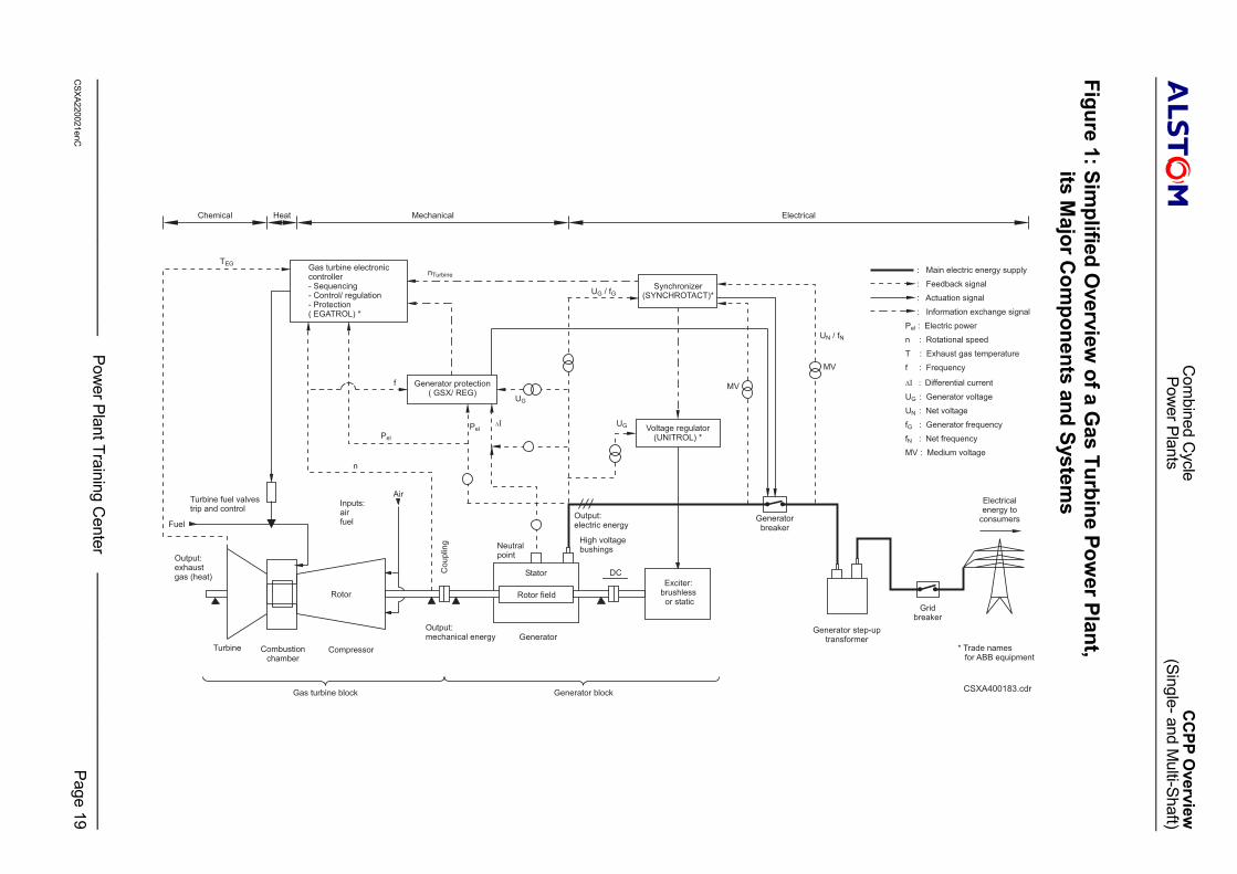
Refer to Figure 1.ALSTOM produces a variety of gas turbosets which differ in:� configuration and� electric power output.
However, the basic energy conversion process from chemical energy to mechanical energy toelectrical energy is similar from machine to machine.The supply of electric energy from a gas turbine power plant requires the use of:� a gas turbine� a generator� an exciter� generator bushings� a generator breaker� a generator step-up transformer and� a grid breaker.The role of each will be briefly described.
Combined Cycle CCPP OverviewPower Plants (Single- and Multi-Shaft)
———————————————— Power Plant Training Center ————————————————CSXA220021enC Page 7
����
Gas Turbine Main Components and Functional Principle
Figure 1 Gas TurbineThe gas turbine is composed of three processing elements:� an air compressor� a combustion chamber and� the turbine itself
The turbine itself:� Converts the thermal energy contained in the combustion gas into mechanical energy at
the coupling and� Is the prime mover that drives the generator and the compressor.� Is driven by hot, compressed combustion gas that strikes blading mounted on the rotor,
and causes it to turn.� After the combustion gas passes through the turbine it is discharged to atmosphere and
is called exhaust gas
The combustion gas that drives the turbine is supplied by the combustion chamber. The latterone:� Converts the chemical energy of the fuel into heat and� Is an enclosed, pressurized firing place where air and liquid and/or gaseous fuel are
continuously burned.
The pressurized air required for combustion is delivered by the compressor. The latter one:� Converts mechanical energy into pneumatic energy and� Is driven by the turbine through a common shaft.
� The air within the compressor is pressurized with the help of rotating and stationaryblading.
� Pressurized air is also used for sealing and cooling of the set.
Fuel Throughput ControlThe fuel throughput to the combustion chamber is controlled by the appropriate setting ofcontrol valves, which can assume, hold and change to any position between fully closed andfully open.

Combined Cycle CCPP OverviewPower Plants (Single- and Multi-Shaft)
———————————————— Power Plant Training Center ————————————————CSXA220021enC Page 8
����
Generator Components and Functional Principle
Figure 1 GeneratorThe generator:� Is the driven machine and� Converts the mechanical energy of the turbine into electrical energy.� Is composed of
� A non-movable part called the stator and� A movable part called the rotor.� The latter is coupled to the turbine rotor, either;� directly or� through a rotational speed reduction gear
The rotor:� Is basically a magnet and� Creates a rotating magnetic field inside the machine by means of the excitation or field
winding, often referred to simply as the rotor winding.
The strength of the magnetic field must be adjusted to correspond to the electrical poweroutput of the generator. The consequences of this measurement are:� The generator is kept in synchronism with the grid and� Both generator voltage and the reactive power supplied to the grid are kept within
specified limits.
This is accomplished by means of a direct current:� Referred to as an excitation current and� Passed through the rotor field winding.
The automatic voltage regulator (AVR) equipment controls the excitation current in turn.The latter one controls both:� The terminal voltage of the generator and� The reactive electric power supply to the grid.The stator contains fixed windings inside which an alternating voltage is induced by therotating magnetic field.
(Continued next page)
Combined Cycle CCPP OverviewPower Plants (Single- and Multi-Shaft)
———————————————— Power Plant Training Center ————————————————CSXA220021enC Page 9
����
Generator Components and Functional Principle (continued)
Figure 1 ExciterThe exciter provides the direct current (DC) for the windings of the generator’s rotatingmagnetic field.� Two types of exciters are used:
� brushless and� static
Both perform the same function.
Generator BushingsThe generator’s bushings:� Provide the connection that enables the electric energy of the generator to be delivered to
the outside world.� Are mounted on the generator stator housing and� Receive the high voltage (HV) output of the stator windings.
The Generator BreakerThe generator breaker provides the electrical connection between the generator’s bushingsand the step-up transformer.
Main Step-up TransformerThe main step-up transformer:� Is used to match the outlet voltage of the generator to the voltage of the grid or network.� Also works like an electric buffer in case of short circuit in the grid, protecting the
generator
Grid BreakerThe grid breaker:� Provides the electrical connection between the substation and the grid or network.� Disconnects the gas turboset from the grid in case of network failures, allowing it to run
on island duty.� Is an optional piece of equipment.
Combined Cycle CCPP OverviewPower Plants (Single- and Multi-Shaft)
———————————————— Power Plant Training Center ————————————————CSXA220021enC Page 10
����
Steam Turbine Power Plant OverviewBasic Components of a Steam Turbine Power Plant
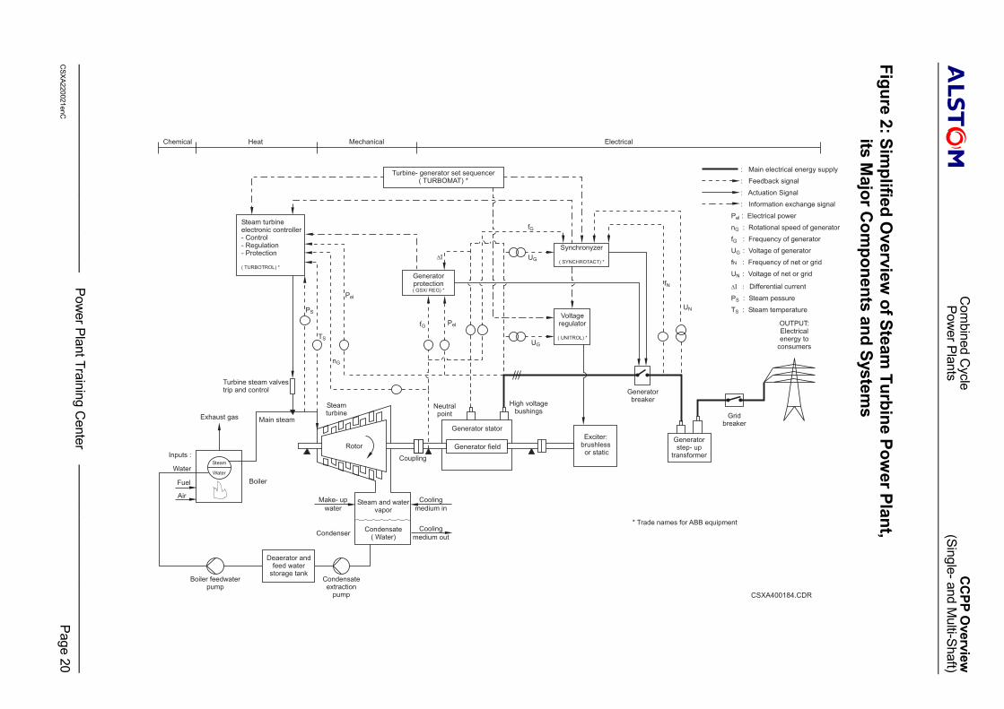
Figure 2 The supply of electricity from a steam power plant requires:� a water steam cycle with:
� a boiler� a steam turbine
� a generator� an exciter� generator bushings� circuit breaker and� step-up transformer.The role of each will be briefly described.
BoilerThe boiler:� Is a place where an energy conversion takes place, namely from chemical energy of the
fuel into heat energy.� The latter one is carried by the combustion gas.
� Uses heat of combustion to convert water into steam, a physical conversion process.To secure the integrity of the boiler, it must be fed continuously with water.
Figure 2 High pressure (HP) steam lines forward the steam raised in the boiler to the steam turbine.� The steam massflow, which passes through the turbine, is regulated by the opening of
control valves.� As steam flows through the turbine it strikes blades on the rotor, causing them to turn.� This is an energy conversion process from heat energy to mechanical energy.
The conversion from mechanical to electrical energy then takes place through the generatorand exciter in a process, which is essentially the same as that described above for the gasturboset.
Combined Cycle CCPP OverviewPower Plants (Single- and Multi-Shaft)
———————————————— Power Plant Training Center ————————————————CSXA220021enC Page 11
����
Combined Cycle Power Plant OverviewMulti-Shaft Arrangement
Figure 3.1 The objective of a combined cycle power plant with multi-shaft arrangement is to deliveronly electricity.To fulfil the above objective, the major components of a multiple shaft combined cyclepower plant are:� One or more gas turbosets.� One or more heat recovery steam boilers (HRSB).� One or more steam turbosets.� The rest of the water-steam cycle.� The balance of plant equipment:
� mechanically and� electrically.
� Control equipment.
The process begins when the gas turboset is placed in operation.� The gas turbine operates on a mixture of air and fuel, which is ignited in the combustion
chamber.� The hot gas is expanded through the turbine, causing the shaft to rotate.
� The turbine-compressor rotor is connected to the generator rotor:� Either directly or� Through a rotational speed reduction gear.
� The generator converts the mechanical energy into electrical energy, which it supplies tothe grid or network.
Exhaust gasses from the combustion process leave the vas turbine at a very high temperature.� If the gas turbine is operated in single cycle, this heat energy is:
� Discharged to atmosphere and� Thus wasted.
� However, if the gas turbine is operated in combined cycle, the hot gas flow is directed toan HRSB.� Here, the heat from the hot gas converts water in the HRSB into steam.
That is, the HRSB links together the gas turbine process and the water steam cycle.
When the steam is at the correct temperature and pressure, it is forwarded to the steamturbine where it expands through the turbine.� Its mechanical power is transmitted via the shaft to the generator, which provides
additional electric power for the grid.
(Continued next page)
Combined Cycle CCPP OverviewPower Plants (Single- and Multi-Shaft)
———————————————— Power Plant Training Center ————————————————CSXA220021enC Page 12
����
Multi-Shaft Arrangement (continued)
Exhausted steam is directed to a condenser, where it is converted to water called condensate.The condensate is then directed to the feed water storage tank-deaerator. Here it is:� Deaerated� Preheated and� StoredThe feed water is then used by the HRSB in the throughput demanded by gas turbinesetelectric power output.
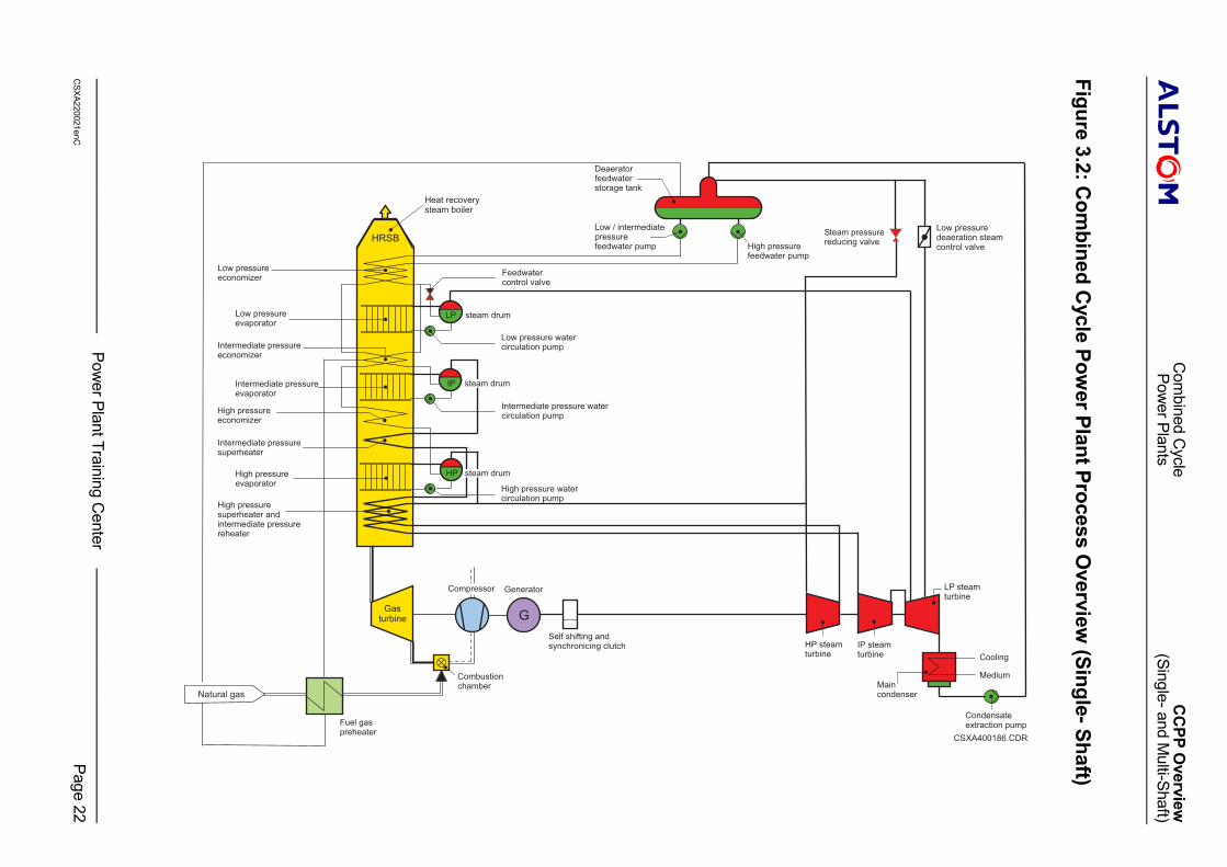
Single-Shaft Arrangement
Figure 3.2 The objective of a combined cycle power plant with single-shaft arrangement is to deliveronly electricity.To fulfil the above objective, he major components of a single shaft combined cycle powerplant are:� A gas turbine.� An alternator.� A self shifting and synchronizing (SSS) clutch.� A water steam cycle, mainly composed of:
� A heat recovery steam boiler.� A steam turbine alternator set.� A condenser.� Condensate extraction pumps.� A deaerator feedwater storage tank.� Boiler feedwater pumps.
� Mechanical balance of plant equipment.� Electrical balance of plant equipment.� Control equipment.
The single shaft combined cycle power plant functions in the same way as the multiple shaftarrangement.� The most important difference is the application of the SSS clutch. The latter one permits
the ST:� To be accelerated AND� To be connected to the alternator, already being driven by the GT
The SSS clutch:� Engages automatically as soon as the torque from the ST shaft becomes positive; that is:
� As soon as the rotational speed of the ST tends to overtable that of the alternator� Disengages automatically as soon as the torque of the ST shaft becomes negative
Combined Cycle CCPP OverviewPower Plants (Single- and Multi-Shaft)
———————————————— Power Plant Training Center ————————————————CSXA220021enC Page 13
����
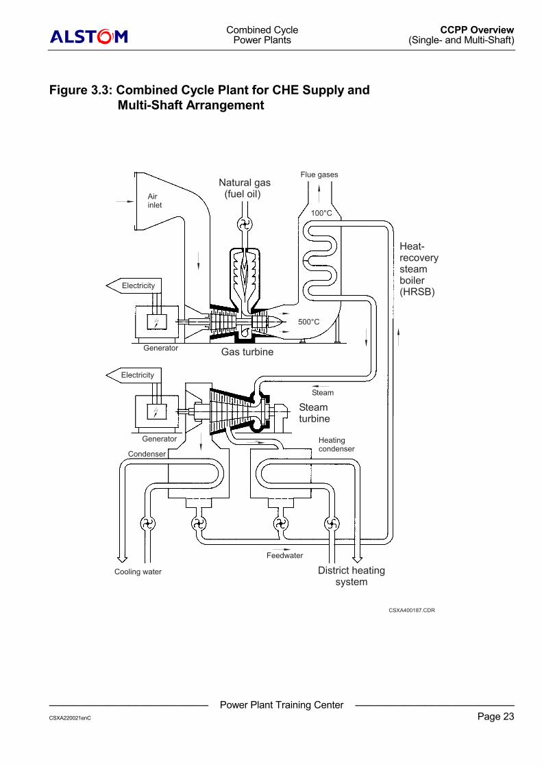
Overview of a Combined Cycle Plant for CHE SupplyMulti-Shaft Arrangement
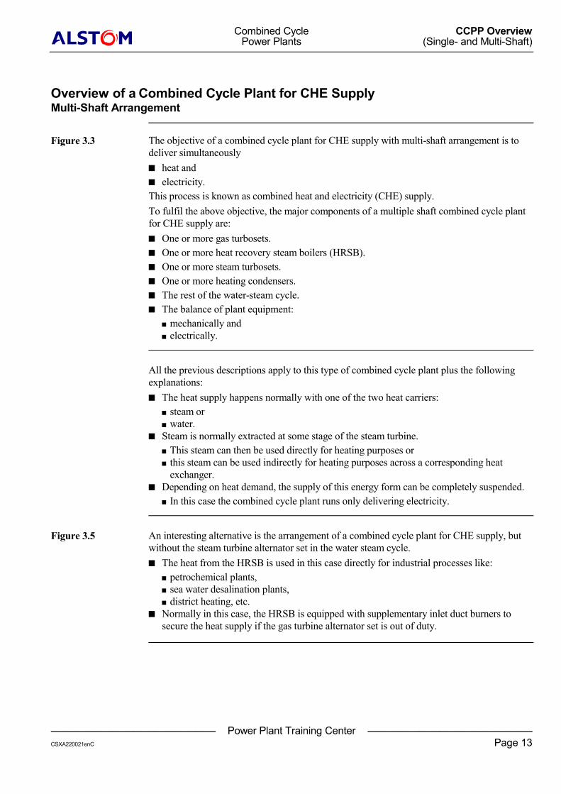
Figure 3.3 The objective of a combined cycle plant for CHE supply with multi-shaft arrangement is todeliver simultaneously� heat and� electricity.This process is known as combined heat and electricity (CHE) supply.To fulfil the above objective, the major components of a multiple shaft combined cycle plantfor CHE supply are:� One or more gas turbosets.� One or more heat recovery steam boilers (HRSB).� One or more steam turbosets.� One or more heating condensers.� The rest of the water-steam cycle.� The balance of plant equipment:
� mechanically and� electrically.
All the previous descriptions apply to this type of combined cycle plant plus the followingexplanations:� The heat supply happens normally with one of the two heat carriers:
� steam or� water.
� Steam is normally extracted at some stage of the steam turbine.� This steam can then be used directly for heating purposes or� this steam can be used indirectly for heating purposes across a corresponding heat
exchanger.� Depending on heat demand, the supply of this energy form can be completely suspended.
� In this case the combined cycle plant runs only delivering electricity.
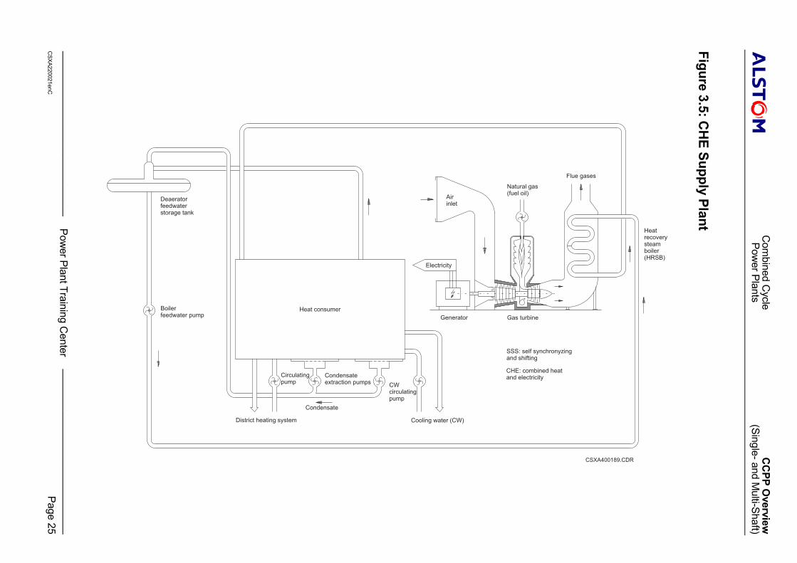
Figure 3.5 An interesting alternative is the arrangement of a combined cycle plant for CHE supply, butwithout the steam turbine alternator set in the water steam cycle.� The heat from the HRSB is used in this case directly for industrial processes like:
� petrochemical plants,� sea water desalination plants,� district heating, etc.
� Normally in this case, the HRSB is equipped with supplementary inlet duct burners tosecure the heat supply if the gas turbine alternator set is out of duty.
Combined Cycle CCPP OverviewPower Plants (Single- and Multi-Shaft)
———————————————— Power Plant Training Center ————————————————CSXA220021enC Page 14
����
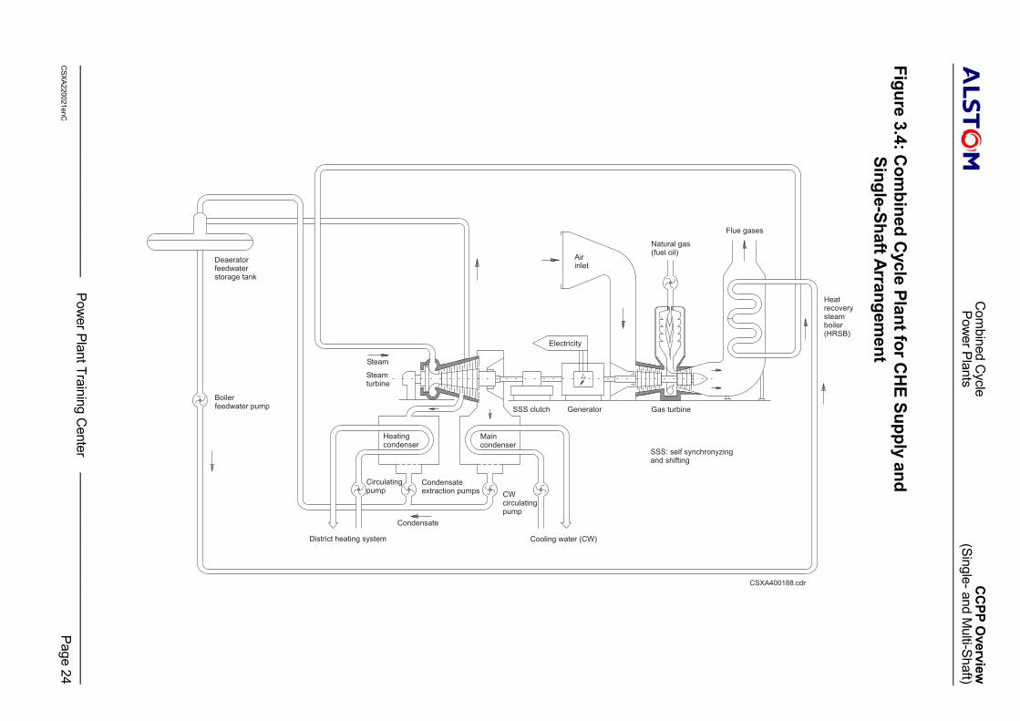
Overview of a Combined Cycle Plant for CHE SupplySingle-Shaft Arrangement
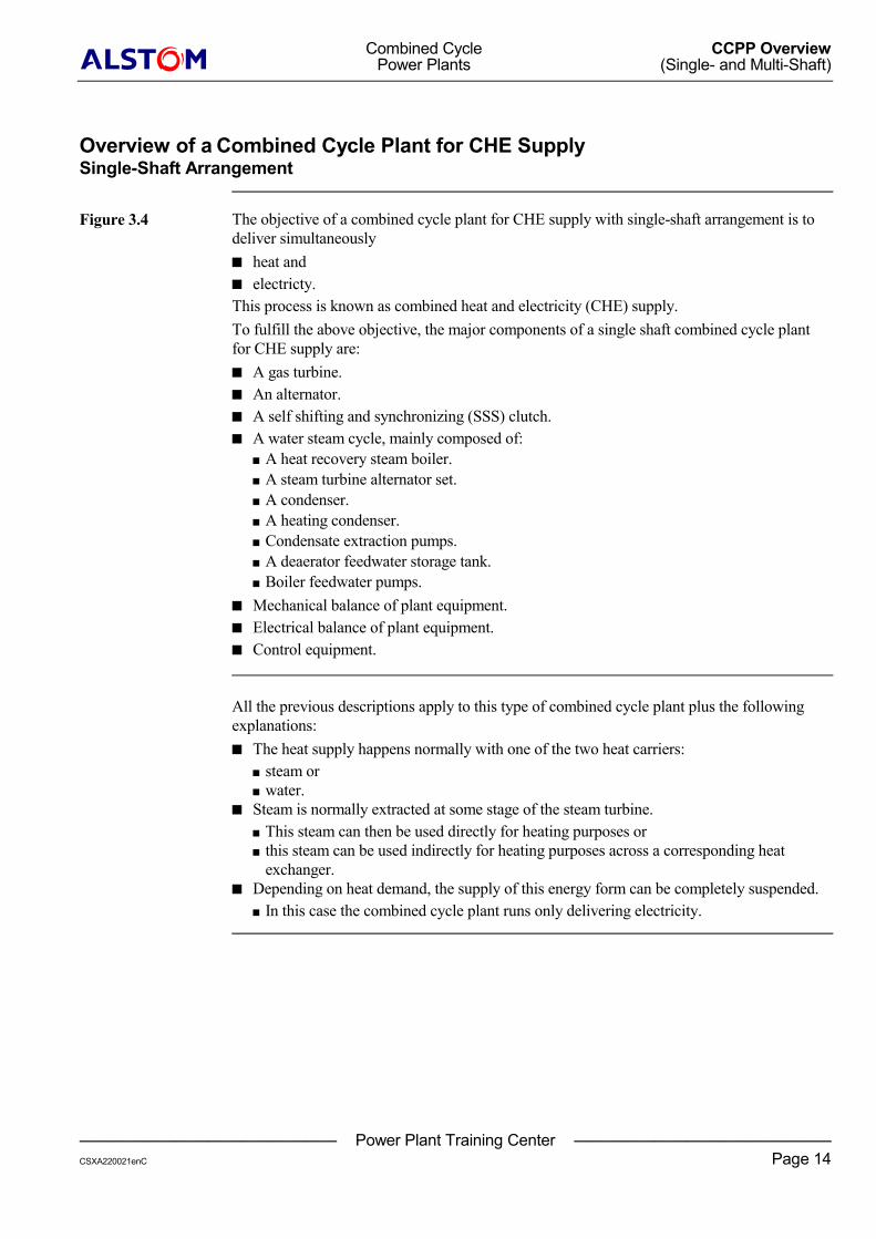
Figure 3.4 The objective of a combined cycle plant for CHE supply with single-shaft arrangement is todeliver simultaneously� heat and� electricty.This process is known as combined heat and electricity (CHE) supply.To fulfill the above objective, the major components of a single shaft combined cycle plantfor CHE supply are:� A gas turbine.� An alternator.� A self shifting and synchronizing (SSS) clutch.� A water steam cycle, mainly composed of:
� A heat recovery steam boiler.� A steam turbine alternator set.� A condenser.� A heating condenser.� Condensate extraction pumps.� A deaerator feedwater storage tank.� Boiler feedwater pumps.
� Mechanical balance of plant equipment.� Electrical balance of plant equipment.� Control equipment.
All the previous descriptions apply to this type of combined cycle plant plus the followingexplanations:� The heat supply happens normally with one of the two heat carriers:
� steam or� water.
� Steam is normally extracted at some stage of the steam turbine.� This steam can then be used directly for heating purposes or� this steam can be used indirectly for heating purposes across a corresponding heat
exchanger.� Depending on heat demand, the supply of this energy form can be completely suspended.
� In this case the combined cycle plant runs only delivering electricity.
Combined Cycle CCPP OverviewPower Plants (Single- and Multi-Shaft)
———————————————— Power Plant Training Center ————————————————CSXA220021enC Page 15
����
Control and Protection System Overview
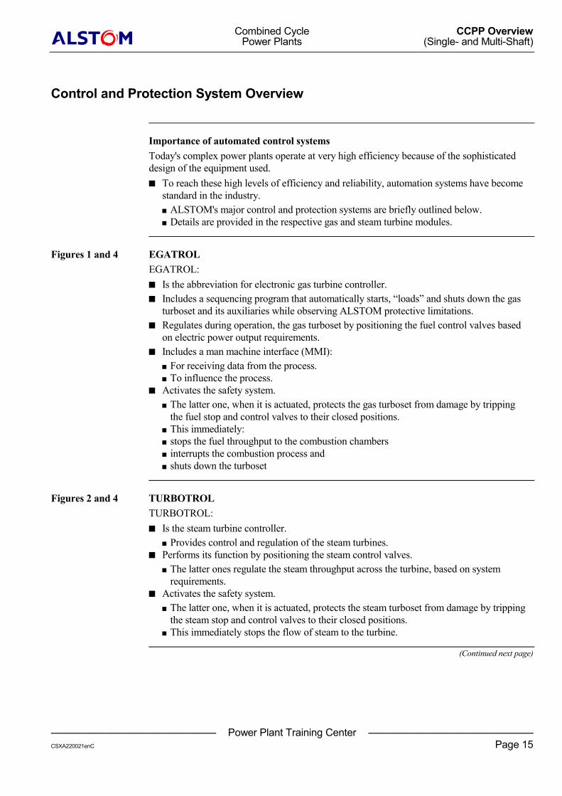
Importance of automated control systemsToday's complex power plants operate at very high efficiency because of the sophisticateddesign of the equipment used.� To reach these high levels of efficiency and reliability, automation systems have become
standard in the industry.� ALSTOM's major control and protection systems are briefly outlined below.� Details are provided in the respective gas and steam turbine modules.
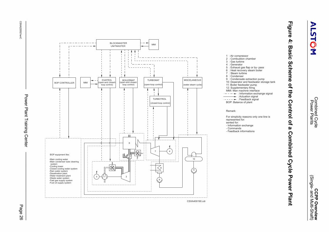
Figures 1 and 4 EGATROLEGATROL:� Is the abbreviation for electronic gas turbine controller.� Includes a sequencing program that automatically starts, “loads” and shuts down the gas
turboset and its auxiliaries while observing ALSTOM protective limitations.� Regulates during operation, the gas turboset by positioning the fuel control valves based
on electric power output requirements.� Includes a man machine interface (MMI):
� For receiving data from the process.� To influence the process.
� Activates the safety system.� The latter one, when it is actuated, protects the gas turboset from damage by tripping
the fuel stop and control valves to their closed positions.� This immediately:� stops the fuel throughput to the combustion chambers� interrupts the combustion process and� shuts down the turboset
Figures 2 and 4 TURBOTROLTURBOTROL:� Is the steam turbine controller.
� Provides control and regulation of the steam turbines.� Performs its function by positioning the steam control valves.
� The latter ones regulate the steam throughput across the turbine, based on systemrequirements.
� Activates the safety system.� The latter one, when it is actuated, protects the steam turboset from damage by tripping
the steam stop and control valves to their closed positions.� This immediately stops the flow of steam to the turbine.
(Continued next page)
Combined Cycle CCPP OverviewPower Plants (Single- and Multi-Shaft)
———————————————— Power Plant Training Center ————————————————CSXA220021enC Page 16
����
Control and Protection System Overview (continued)
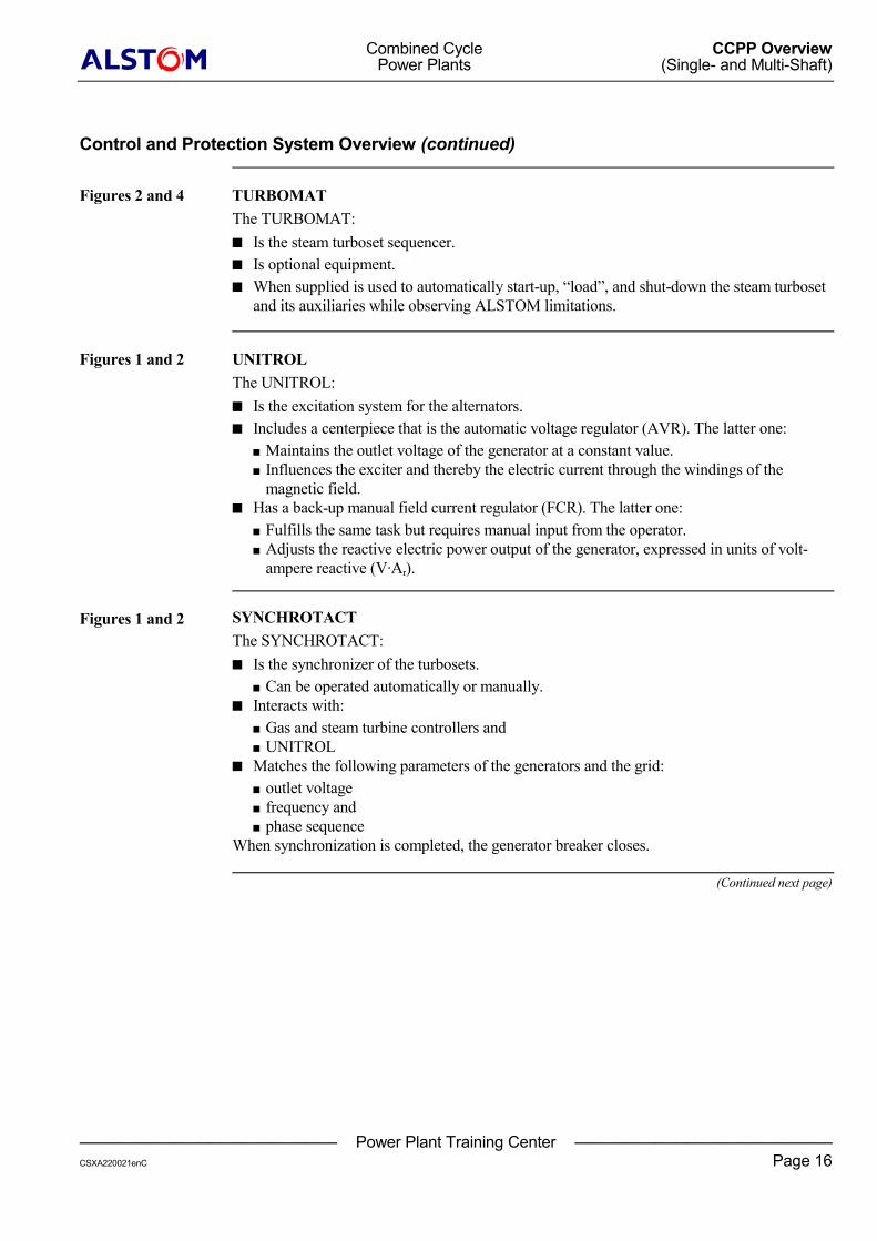
Figures 2 and 4 TURBOMATThe TURBOMAT:� Is the steam turboset sequencer.� Is optional equipment.� When supplied is used to automatically start-up, “load”, and shut-down the steam turboset
and its auxiliaries while observing ALSTOM limitations.
Figures 1 and 2 UNITROLThe UNITROL:� Is the excitation system for the alternators.� Includes a centerpiece that is the automatic voltage regulator (AVR). The latter one:
� Maintains the outlet voltage of the generator at a constant value.� Influences the exciter and thereby the electric current through the windings of the
magnetic field.� Has a back-up manual field current regulator (FCR). The latter one:
� Fulfills the same task but requires manual input from the operator.� Adjusts the reactive electric power output of the generator, expressed in units of volt-
ampere reactive (V·Ar).
Figures 1 and 2 SYNCHROTACTThe SYNCHROTACT:� Is the synchronizer of the turbosets.
� Can be operated automatically or manually.� Interacts with:
� Gas and steam turbine controllers and� UNITROL
� Matches the following parameters of the generators and the grid:� outlet voltage� frequency and� phase sequence
When synchronization is completed, the generator breaker closes.
(Continued next page)
Combined Cycle CCPP OverviewPower Plants (Single- and Multi-Shaft)
———————————————— Power Plant Training Center ————————————————CSXA220021enC Page 17
����
Control and Protection System Overview (continued)
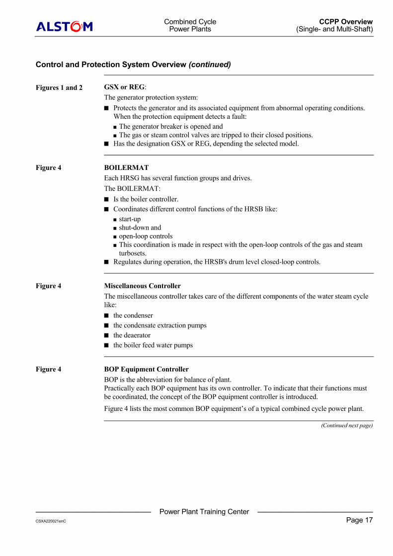
Figures 1 and 2 GSX or REG:The generator protection system:� Protects the generator and its associated equipment from abnormal operating conditions.
When the protection equipment detects a fault:� The generator breaker is opened and� The gas or steam control valves are tripped to their closed positions.
� Has the designation GSX or REG, depending the selected model.
Figure 4 BOILERMATEach HRSG has several function groups and drives.The BOILERMAT:� Is the boiler controller.� Coordinates different control functions of the HRSB like:
� start-up� shut-down and� open-loop controls� This coordination is made in respect with the open-loop controls of the gas and steam
turbosets.� Regulates during operation, the HRSB's drum level closed-loop controls.
Figure 4 Miscellaneous ControllerThe miscellaneous controller takes care of the different components of the water steam cyclelike:� the condenser� the condensate extraction pumps� the deaerator� the boiler feed water pumps
Figure 4 BOP Equipment ControllerBOP is the abbreviation for balance of plant.Practically each BOP equipment has its own controller. To indicate that their functions mustbe coordinated, the concept of the BOP equipment controller is introduced.Figure 4 lists the most common BOP equipment’s of a typical combined cycle power plant.
(Continued next page)
Combined Cycle CCPP OverviewPower Plants (Single- and Multi-Shaft)
———————————————— Power Plant Training Center ————————————————CSXA220021enC Page 18
����
Control and Protection System Overview (continued)
Figure 4 BLOCKMASTERThe BLOCKMASTER:� Is the overimposed power plant controller.� Ensures that each major component in the CCPP process is brought into service or
removed from service in the proper sequence.� Is also called UNITMASTER.� Includes several MMIs:
� For receiving data from the process.� To influence the process.
Summary
This section:� Described the components used to deliver electricity from modern gas and steam turbine
power plants.� Included information of how those single processes are joined to operate at higher
efficiency in a combined cycle arrangement to deliver� only electricity or� simultaneously electricity and heat.
To ensure that you understand the material covered, review each of the Objectives (page 5).
Com
bined Cycle
CCPP Overview
Power Plants
(Single- and Multi-Shaft)
——
——
——
——
——
——
——
——
Power Plant Training C
enter—
——
——
——
——
——
——
——
—C
SXA220021enCPage 19
��
��
Figure 1: Simplified O
verview of a G
as Turbine Power Plant,
its Major C
omponents and System
s
TEG
Fuel
Chemical Heat
Air
UG
UG
��Pel
Pel
n
f
Inputs:airfuel
Generator block
Electrical
Generatorbreaker
Voltage regulator(UNITROL) *
Output:exhaustgas (heat)
Turbine Combustionchamber
Compressor
Couplin
g
GeneratorGenerator step-up
transformer
Rotor field
Stator
Rotor
* Trade namesfor ABB equipment
High voltagebushings
Output:electric energy
Output:mechanical energy
Exciter:brushlessor static
Gridbreaker
Synchronizer(SYNCHROTACT)*
Gas turbine electroniccontroller- Sequencing- Control/ regulation- Protection( EGATROL) *
Generator protection( GSX/ REG)
Turbine fuel valvestrip and control
Neutralpoint
Electricalenergy to
consumers
U / fG G
nTurbine
U / fN N
Gas turbine block
Mechanical
: Main electric energy supply
: Feedback signal
: Actuation signal
: Information exchange signal
P : Electric power
n : Rotational speed
T : Exhaust gas temperature
f : Frequency
Differential current
U : Generator voltage
U : Net voltage
f : Generator frequency
f : Net frequency
MV : Medium voltage
el
G
N
G
N
������
MV
MV
DC
CSXA400183.cdr
Com
bined Cycle
CCPP Overview
Power Plants
(Single- and Multi-Shaft)
——
——
——
——
——
——
——
——
Power Plant Training C
enter—
——
——
——
——
——
——
——
—C
SXA220021enCPage 20
��
��
Figure 2: Simplified O
verview of Steam
Turbine Power Plant,
its Major C
omponents and System
s
CSXA400184.CDR
Rotor
Generatorbreaker
Steam
Water
Coupling
PS
TS
Pel
fG Pel
fG
UG
fN
UN
UG
��
nG
Electrical
Condensateextraction
pump
Condenser
* Trade names for ABB equipment
Generator field
Generator stator
High voltagebushings
Exciter:brushlessor static
Gridbreaker
Neutralpoint
OUTPUT:Electricalenergy to
consumers
Condensate( Water)
Steam and watervapor
Generatorstep- up
transformer
BoilerFuel
Air
Deaerator andfeed water
storage tankBoiler feedwater
pump
Make- up
water
Cooling
medium in
Cooling
medium out
Exhaust gas
Steamturbine
Main steam
Turbine steam valvestrip and control
Steam turbineelectronic controller- Control- Regulation- Protection
( TURBOTROL) *
Generatorprotection( GSX/ REG) *
Voltageregulator
( UNITROL) *
Synchronyzer
( SYNCHROTACT) *
Turbine- generator set sequencer( TURBOMAT) *
Inputs :
Water
: Main electrical energy supply
: Feedback signal
: Actuation Signal
: Information exchange signal
P : Electrical power
n : Rotational speed of generator
f : Frequency of generator
U : Voltage of generator
f : Frequency of net or grid
U : Voltage of net or grid
Differential current
P : Steam pessure
T : Steam temperature
el
G
G
G
N
N
S
S
�� �
Chemical Heat Mechanical

Com
bined Cycle
CCPP Overview
Power Plants
(Single- and Multi-Shaft)
——
——
——
——
——
——
——
——
Power Plant Training C
enter—
——
——
——
——
——
——
——
—C
SXA220021enCPage 21
��
��
Figure 3.1: Com
bined Cycle Pow
er Plant Process Overview
(Multi- Shaft)
CSXA400185.cdr
HRSB
G G
Condensateextraction pump
Maincondenser
Cooling
Medium
HP steamturbine
LP steamturbine
IP steamturbine
Deaeratorfeedwaterstorage tank
High pressurefeedwater pump
Low / intermediatepressurefeedwater pump
Steam pressurereducing valve
Combustionchamber
Generator
Gasturbine
Natural gas
Fuel gaspreheater
Low pressureeconomizer
Intermediate pressureeconomizer
Intermediate pressureevaporator
Intermediate pressuresuperheater
High pressureevaporator
High pressuresuperheater andintermediate pressurereheater
LP steam drum
Low pressure watercirculation pump
Intermediate pressure watercirculation pump
High pressure watercirculation pump
Low pressuredeaeration steamcontrol valve
Feedwatercontrol valve
Heat recoverysteam boiler
High pressureeconomizer
Generator
IP steam drum
HP steam drum
Compressor
Low pressureevaporator
Com
bined Cycle
CCPP Overview
Power Plants
(Single- and Multi-Shaft)
——
——
——
——
——
——
——
——
Power Plant Training C
enter—
——
——
——
——
——
——
——
—C
SXA220021enCPage 22
��
��
Figure 3.2: Com
bined Cycle Pow
er Plant Process Overview
(Single- Shaft)
G
Natural gas
Fuel gaspreheater
Condensateextraction pump
Maincondenser
Cooling
Medium
HP steamturbine
LP steamturbine
IP steamturbine
Deaeratorfeedwaterstorage tank
High pressurefeedwater pump
Low / intermediatepressurefeedwater pump
Steam pressurereducing valveHRSB
Combustionchamber
Generator
Self shifting andsynchronicing clutch
Gasturbine
Low pressureeconomizer
Low pressureevaporator
Intermediate pressureeconomizer
Intermediate pressureevaporator
Intermediate pressuresuperheater
High pressureevaporator
High pressuresuperheater andintermediate pressurereheater
LP steam drum
Low pressure watercirculation pump
Intermediate pressure watercirculation pump
High pressure watercirculation pump
Low pressuredeaeration steamcontrol valve
Feedwatercontrol valve
Heat recoverysteam boiler
High pressureeconomizer
IP steam drum
HP steam drum
Compressor
CSXA400186.CDR
Combined Cycle CCPP OverviewPower Plants (Single- and Multi-Shaft)
———————————————— Power Plant Training Center ————————————————CSXA220021enC Page 23
����
Figure 3.3: Combined Cycle Plant for CHE Supply andMulti-Shaft Arrangement
CSXA400187.CDR
Natural gas(fuel oil)
Flue gases
Airinlet
100°C
Heat-recoverysteamboiler(HRSB)
500°C
Electricity
Generator Gas turbine
Electricity
Generator
Condenser
Steam
Steamturbine
Heatingcondenser
Cooling water
Feedwater
District heatingsystem
Com
bined Cycle
CCPP Overview
Power Plants
(Single- and Multi-Shaft)
——
——
——
——
——
——
——
——
Power Plant Training C
enter—
——
——
——
——
——
——
——
—C
SXA220021enCPage 24
��
��
Figure 3.4: Com
bined Cycle Plant for C
HE Supply and
Single-Shaft Arrangement
CSXA400188.cdr
Heatrecoverysteamboiler(HRSB)
Flue gases
Airinlet
Natural gas(fuel oil)
Gas turbineGeneratorSSS clutch
Electricity
Maincondenser
CWcirculatingpump
Cooling water (CW)
Heatingcondenser
Condensateextraction pumps
Circulatingpump
District heating system
Steam
Steamturbine
Deaeratorfeedwaterstorage tank
Boilerfeedwater pump
SSS: self synchronyzingand shifting
Condensate
Com
bined Cycle
CCPP Overview
Power Plants
(Single- and Multi-Shaft)
——
——
——
——
——
——
——
——
Power Plant Training C
enter—
——
——
——
——
——
——
——
—C
SXA220021enCPage 25
��
��
Figure 3.5: CHE Supply Plant
CSXA400189.CDR
Condensate
Heat consumer
Heatrecoverysteamboiler(HRSB)
Flue gases
Airinlet
Natural gas(fuel oil)
Gas turbineGenerator
Electricity
CWcirculatingpump
Cooling water (CW)
Condensateextraction pumps
Circulatingpump
District heating system
Deaeratorfeedwaterstorage tank
Boilerfeedwater pump
SSS: self synchronyzingand shifting
CHE: combined heatand electricity
Com
bined Cycle
CCPP Overview
Power Plants
(Single- and Multi-Shaft)
——
——
——
——
——
——
——
——
Power Plant Training C
enter—
——
——
——
——
——
——
——
—C
SXA220021enCPage 26
��
��
Figure 4: Basic Schem
e of the Control of a C
ombined C
ycle Power PlantCSXA400190.cdr
1 : Air compressor2 : Combustion chamber3 : Gas turbine4 : Generator5 : Exhaust gas flap or by- pass6 : Heat recovery steam boiler7 : Steam turbine8 : Condenser9 : Condensate extraction pump10: Deaerator and feedwater storage tank11: Boiler feedwater pump12: Supplementary firingMMI: Man machine interface
: Information exchange signal: Actuation signal: Feedback signal
BOP: Balance of plant
Remark:
For simplicity reasons only one line isrepresented for:sented for:- Information exchange- Commands- Feedback informations
MMI
BOP CONTROLLER MMI
EGATROL(open-and closed-
loop control)
TURBOMAT
(open-loop control)
BOILERMAT(open-and closed-
loop control)
MISCELANEOUS
(water steam cycle)
BLOCKMASTER
UNITMASTER
TURBOTROL
(closed-loop control)
BOP equipment like:
-Main cooling water-Main condenser tube cleaningsystem
-Cooling tower-Closed cooling water system-Rain water system-Desalination plant-Water treatment plant-Waste water system-Fael gas supply system-Fuel oil supply system
4 1 3
2
4
5
6
10
118
9
7
12
Com
bined Cycle
CCPP Overview
Power Plants
(Single- and Multi-Shaft)
——
——
——
——
——
——
——
——
Power Plant Training C
enter—
——
——
——
——
——
——
——
—C
SXA220021enCPage 27
��
��
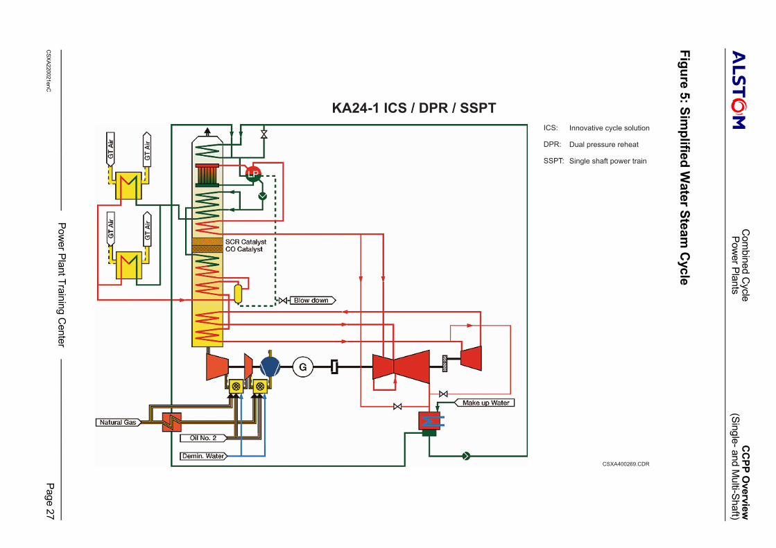
Figure 5: Simplified W
ater Steam C
ycle
CSXA400269.CDR
ICS:
DPR:
SSPT:
KA24-1 ICS / DPR / SSPT
Innovative cycle solution
Dual pressure reheat
Single shaft power train