Embed Size (px)
Citation preview

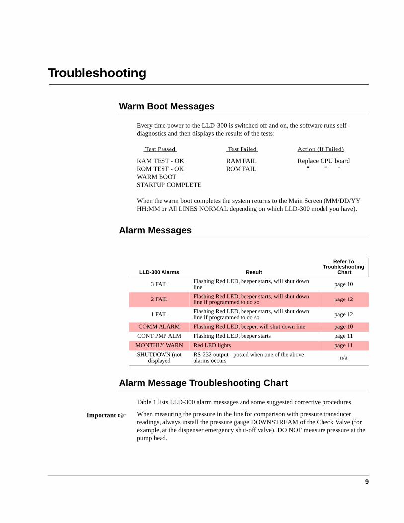
LLD-300
LCD1
BACK ENTER SELECT
SILENT STARTTEST
U10
C1
U11
U5
U1
J1
LED1
U16
U4
U14
U15
U8
U7
U12
U2
LLD
-300
CP
U B
OA
RD
DEFAULT(X2)DCBA
J2
ble to Powerply Board
P
actoryn)
e (A), theas Hosted to a
Positions
Environmental ProductsVEEDER-ROOT
Manual No: 577013-602 ● Revision: D
Troubleshooting Manual
Notice
Veeder-Root makes no warranty of any kind with regard to this publication, including, but not limited to, the implied warranties of merchantability and fitness for a particular purpose.
Veeder-Root shall not be liable for errors contained herein or for incidental or consequential damages in connection with the furnishing, performance, or use of this publication.
Veeder-Root reserves the right to change system options or features, or the information contained in this publication.
This publication contains proprietary information which is protected by copyright. All rights reserved. No part of this publication may be photocopied, reproduced, or translated to another language without the prior written consent of Veeder-Root.
Veeder-Root 1999. All rights reserved.
Contents
iii
IntroductionVeeder-Root Manual 577013-546 Required ................................................. 1Return Shipping ............................................................................................. 1Safety Symbols ............................................................................................. 2
LLD-300 SystemWPLLD Sensor and SwiftCheck Valve .................................................... 4
High Altitude Installation Precaution for the WPLLD Sensor ......... 4LLD-300 Console Components ..................................................................... 4
Power Supply Board ................................................................................ 4CPU Board .................................................................................................... 6Line Leak Tests ............................................................................................. 7
3 gph Leak Test ............................................................................. 7MID leak test (modified 3 gph test) ................................................ 70.2 gph Leak Test .......................................................................... 70.1 gph Leak Test .......................................................................... 8
TroubleshootingWarm Boot Messages ................................................................................... 9Alarm Messages ............................................................................................ 9Alarm Message Troubleshooting Chart .......................................................... 9PROM Chip Replacement (Software Upgrade) ...........................................13
Replacing the CPU Board......................................................................16Cold Boot Procedure ...................................................................................16
Overriding the Automatic 0.2 gph Test ..................................................17Replacing the Power Supply Board .......................................................18Fuse F1..................................................................................................18Visually Checking System Operation.....................................................19
Using the Diagnostic Menu .........................................................................19
LLD-300 System SpecificationsPhysical Specifications ................................................................................21
Console..................................................................................................21WPLLD Sensor ......................................................................................21SwiftCheck Valve (if used) .....................................................................21
Environmental Specifications ......................................................................21Electrical Specifications ...............................................................................21Software Specifications ...............................................................................22RS-232 Serial Interface (Optional) ..............................................................22Signal Input Specifications ..........................................................................22
Contents
iv
Signal Output Specifications ....................................................................... 22Front Panel User Interface .......................................................................... 22Leak Testing ............................................................................................... 23
RS-232 Serial Interface - OptionalDB9 Connector Pin-Outs ............................................................................ 24RS-232 Serial Interface Port Settings ......................................................... 24RS-232 Serial Commands .......................................................................... 25
Control Functions .................................................................................. 25Operational Reports .............................................................................. 25Setup Commands.................................................................................. 25Diagnostic Commands .......................................................................... 25
RS-232 Serial Command Formats .............................................................. 26
Glossary .................................................................................. Glossary-1
FiguresFigure 1. Power Supply Board Component Locations .......................... 5Figure 2. CPU Board Components ........................................................ 6Figure 5. Removing PROM Chip ......................................................... 14Figure 6. Replacing PROM Chip ......................................................... 15Figure 7. Diagnostic Menu .................................................................. 20Figure 8. DB-9, RS-232 Pin-Outs ........................................................ 24
1
Introduction
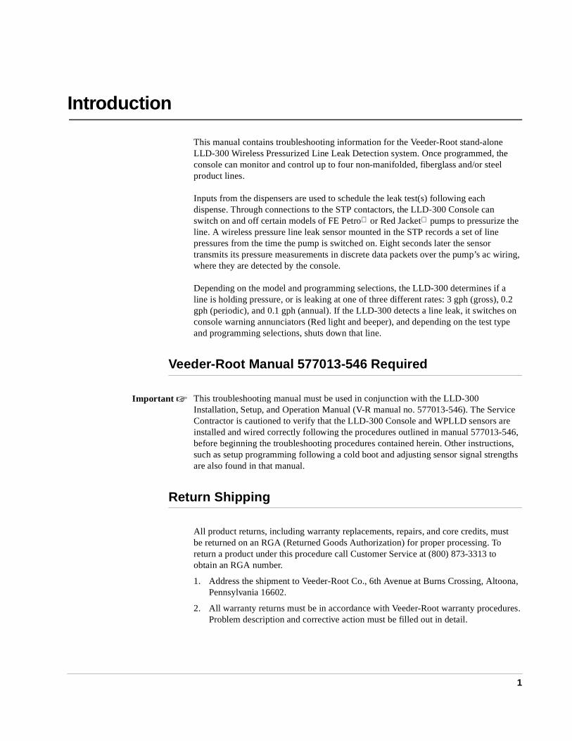
This manual contains troubleshooting information for the Veeder-Root stand-alone LLD-300 Wireless Pressurized Line Leak Detection system. Once programmed, the console can monitor and control up to four non-manifolded, fiberglass and/or steel product lines.
Inputs from the dispensers are used to schedule the leak test(s) following each dispense. Through connections to the STP contactors, the LLD-300 Console can switch on and off certain models of FE Petro or Red Jacket pumps to pressurize the line. A wireless pressure line leak sensor mounted in the STP records a set of line pressures from the time the pump is switched on. Eight seconds later the sensor transmits its pressure measurements in discrete data packets over the pump’s ac wiring, where they are detected by the console.
Depending on the model and programming selections, the LLD-300 determines if a line is holding pressure, or is leaking at one of three different rates: 3 gph (gross), 0.2 gph (periodic), and 0.1 gph (annual). If the LLD-300 detects a line leak, it switches on console warning annunciators (Red light and beeper), and depending on the test type and programming selections, shuts down that line.
Veeder-Root Manual 577013-546 Required
This troubleshooting manual must be used in conjunction with the LLD-300 Installation, Setup, and Operation Manual (V-R manual no. 577013-546). The Service Contractor is cautioned to verify that the LLD-300 Console and WPLLD sensors are installed and wired correctly following the procedures outlined in manual 577013-546, before beginning the troubleshooting procedures contained herein. Other instructions, such as setup programming following a cold boot and adjusting sensor signal strengths are also found in that manual.
Return Shipping
All product returns, including warranty replacements, repairs, and core credits, must be returned on an RGA (Returned Goods Authorization) for proper processing. To return a product under this procedure call Customer Service at (800) 873-3313 to obtain an RGA number.
1. Address the shipment to Veeder-Root Co., 6th Avenue at Burns Crossing, Altoona, Pennsylvania 16602.
2. All warranty returns must be in accordance with Veeder-Root warranty procedures. Problem description and corrective action must be filled out in detail.
Important ☞
Safety Symbols Introduction
2
Safety Symbols
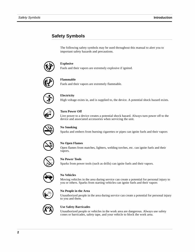
The following safety symbols may be used throughout this manual to alert you to important safety hazards and precautions.
ExplosiveFuels and their vapors are extremely explosive if ignited.
FlammableFuels and their vapors are extremely flammable.
ElectricityHigh voltage exists in, and is supplied to, the device. A potential shock hazard exists.
Turn Power OffLive power to a device creates a potential shock hazard. Always turn power off to the device and associated accessories when servicing the unit.
No SmokingSparks and embers from burning cigarettes or pipes can ignite fuels and their vapors
No Open FlamesOpen flames from matches, lighters, welding torches, etc. can ignite fuels and their vapors.
No Power ToolsSparks from power tools (such as drills) can ignite fuels and their vapors.
No VehiclesMoving vehicles in the area during service can create a potential for personal injury to you or others. Sparks from starting vehicles can ignite fuels and their vapors
No People in the AreaUnauthorized people in the area during service can create a potential for personal injury to you and them.
Use Safety BarricadesUnauthorized people or vehicles in the work area are dangerous. Always use safety cones or barricades, safety tape, and your vehicle to block the work area.
OFF
Safety Symbols Introduction
3
G A S
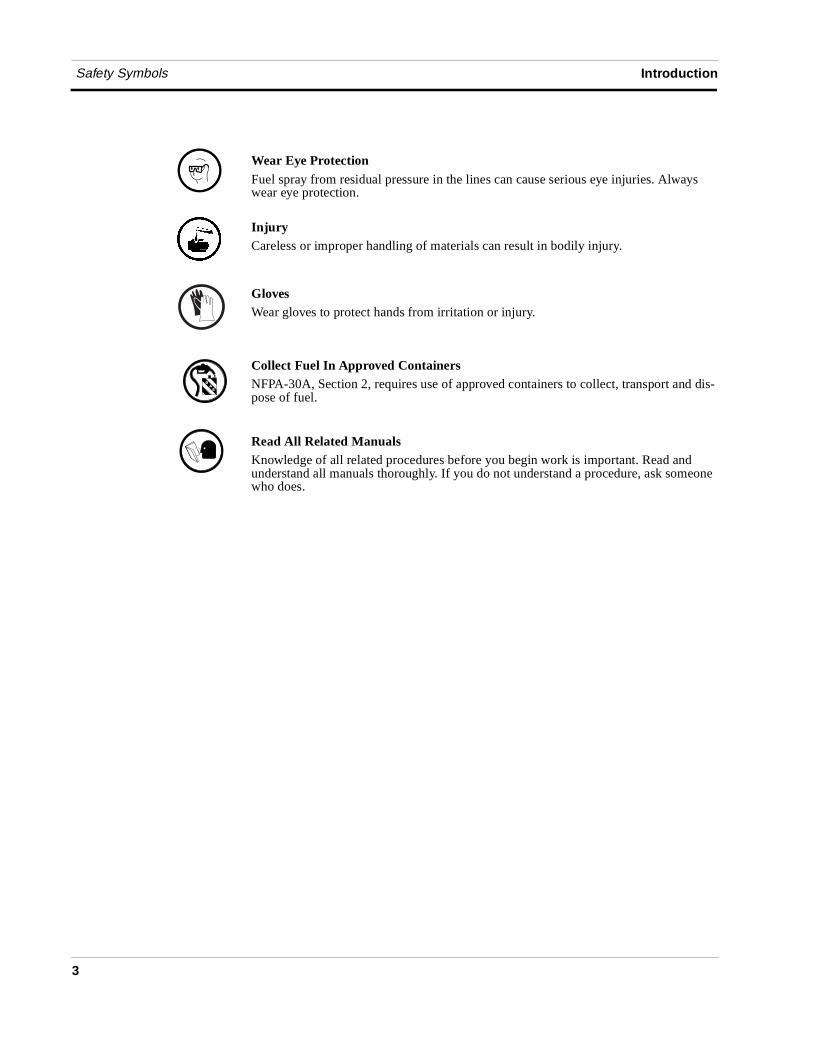
Wear Eye ProtectionFuel spray from residual pressure in the lines can cause serious eye injuries. Always wear eye protection.
InjuryCareless or improper handling of materials can result in bodily injury.
GlovesWear gloves to protect hands from irritation or injury.
Collect Fuel In Approved ContainersNFPA-30A, Section 2, requires use of approved containers to collect, transport and dis-pose of fuel.
Read All Related ManualsKnowledge of all related procedures before you begin work is important. Read and understand all manuals thoroughly. If you do not understand a procedure, ask someone who does.
G A S
4
LLD-300 System
The LLD-300 System consists of the LLD-300 Console which is mounted indoors; a Wireless Pressurized Line Leak sensor which is installed in the STP (for installations with Red Jacket pumps, some models of the console will require a Veeder-Root SwiftCheck valve which is also installed in the STP).
WPLLD Sensor and SwiftCheck Valve The WPLLD sensor and the SwiftCheck valve are not field repairable and must be replaced if faulty.
������������� ��������� ��������� ����������������� ���
The WPLLD sensors are equipped with a vent screw to equalize internal pressure. If the site’s altitude is above 2,000 feet and this vent screw was not opened prior to the sensor’s installation it could be transmitting inaccurate pressure readings. Remove the sensor from the STP and open the vent screw at least two turns, but not more than three turns to vent any internal pressure (Figure 9, page 27, V-R manual no. 577013-546). Retighten the vent screw securely to prevent water from entering and replace the sensor in the pump.
LLD-300 Console Components
The console contains two removable assemblies – a Power Supply board and a CPU board.
Power Supply Board
The Power Supply Board contains the following circuitry:
❑ Controller
❑ WPLLD signal processing
❑ 8-volt switching power supply
❑ LED indicators
❑ RS-232 driver circuit
❑ Beeper
❑ Transistor output (dc switch)
LLD-300 System LLD-300 Console Components
5
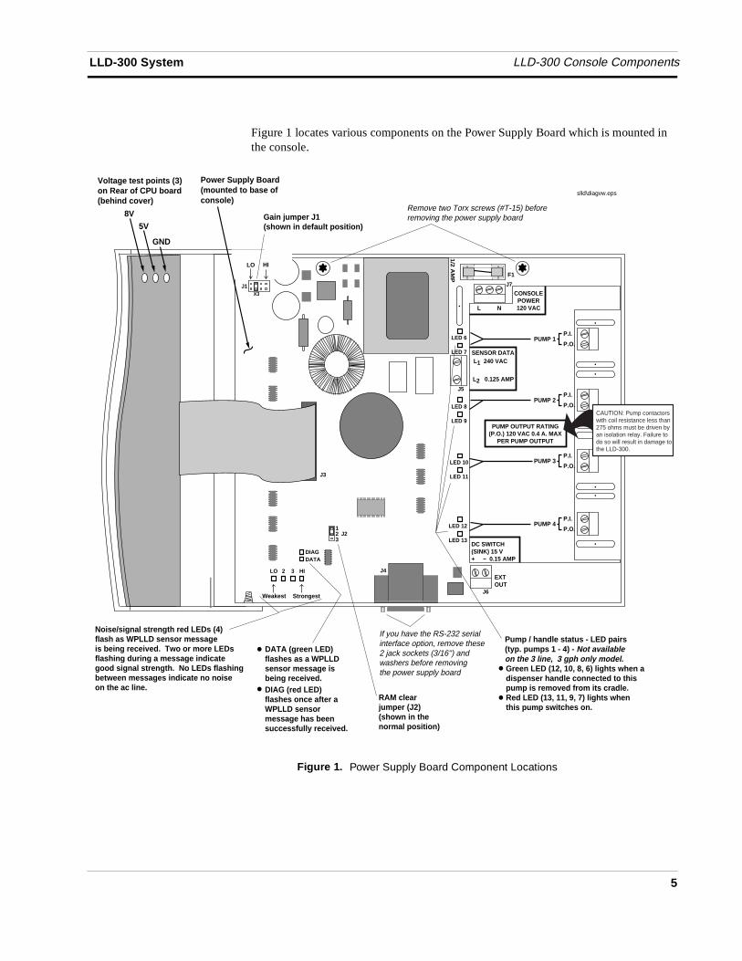
Figure 1 locates various components on the Power Supply Board which is mounted in the console.
Figure 1. Power Supply Board Component Locations
PUMP 1P.I.
P.O.
PUMP 2P.I.
P.O.
PUMP 3P.I.
P.O.
PUMP 4P.I.
P.O.1
DATA
EXT OUT
1/2 AM
P F1
DC SWITCH(SINK) 15 V+ 0.15 AMP
PUMP OUTPUT RATING(P.O.) 120 VAC 0.4 A. MAX
PER PUMP OUTPUT
SENSOR DATAL1 240 VAC
L N
CONSOLEPOWER120 VAC
slld\diagvw.eps
L2 0.125 AMP
X3
Gain jumper J1(shown in default position)
LO HI
Weakest
Noise/signal strength red LEDs (4) flash as WPLLD sensor messageis being received. Two or more LEDs flashing during a message indicate good signal strength. No LEDs flashingbetween messages indicate no noise on the ac line.
Strongest
J223
DIAG
LO 2 3 HI
J6
J5
J3
J7J1
J4
RAM clear jumper (J2)(shown in the normal position)
Power Supply Board(mounted to base ofconsole)
LED 13
LED 12
LED 11
LED 10
LED 9
LED 8
LED 7
LED 6
DATA (green LED)flashes as a WPLLDsensor message isbeing received. DIAG (red LED)flashes once after a WPLLD sensor message has been successfully received.
Green LED (12, 10, 8, 6) lights when a dispenser handle connected to this pump is removed from its cradle.Red LED (13, 11, 9, 7) lights when this pump switches on.
Pump / handle status - LED pairs(typ. pumps 1 - 4) - Not availableon the 3 line, 3 gph only model.
If you have the RS-232 serial interface option, remove these 2 jack sockets (3/16'') and washers before removing the power supply board
Remove two Torx screws (#T-15) before removing the power supply board
GND
5V
8V
Voltage test points (3)on Rear of CPU board(behind cover)
CAUTION: Pump contactors with coil resistance less than 275 ohms must be driven by an isolation relay. Failure to do so will result in damage to the LLD-300.
CPU Board LLD-300 System
6
CPU Board
The CPU board contains the following circuitry:
❑ EEPROM
❑ PROM (replaced for software upgrades)
❑ RAM
❑ 16-character display
❑ LED indicator
❑ Processor
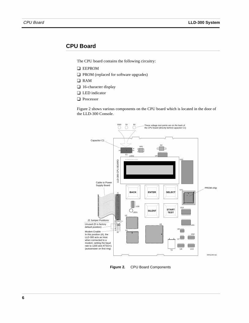
Figure 2 shows various components on the CPU board which is located in the door of the LLD-300 Console.
Figure 2. CPU Board Components
LCD1
BACK ENTER SELECT
SILENT STARTTEST
U10
C1
+
U11
Y2
U5
U1
J1
LED1
U16
5V
D2
U4
U14
U15
U8
U7
U12
U13U9
U2
LLD
-300
CP
U B
OA
RD
DEFAULT(X2)DCBA
J2
Cable to PowerSupply Board
slld\cpubd.eps
Capacitor C1
PROM chip
Unused (D is factorydefault position)
Modem EnableIn this position (A), theLLD-300 acts as Hostwhen connected to a modem; setting the baudrate to 1200 and ATSO=1(autoanswer on first ring)
J2 Jumper Positions
VR1
GND 8V These voltage test points are on the back of the CPU board (directly behind capacitor C1)
LLD-300 System Line Leak Tests
7
Line Leak Tests
Line leak tests are controlled by the LLD-300 software and are determined passed or failed after analyzing two sets of pressure measurements recorded by, and transmitted from, the WPLLD sensor.
Each time a sensor is powered up, it records and transmits a number of pressure readings spaced over a fixed amount of time. In pump-off tests, the first pressure reading from each measurement set is used. In pump-on tests 2 pressure readings from each measurement set are used (the software calculates which two, based upon line length and type entered during setup, and whether a 0.2 or 0.1 gph test is being run).
���������������
The 3 gph (gross) leak test is a pump-off test that is run after every dispense. The total time required for this test is approximately 45 seconds.
Two pump-off pressure measurements are used in this test. The 3 gph test fails if the second measurement is not within 5 psi of the first, or if the pressure readings are less than 10 psi. If a 3 gph test fails it is rerun, and if it fails again, the line is shutdown.
�����������������
The 0.2 gph (periodic) leak test is a pump-on test that can be programmed to run monthly or continuously, or it can be started manually. All 0.2 gph tests are automatically preceded by a 3 gph test (there is a 15 minute delay between the 3 gph and 0.2 gph tests).
The 0.2gph test involves multiple pump on and pressure measurement periods of less than 1 minute spaced 15 minutes apart.
The minimum time required for the 0.2 gph test to run is approximately 30 minutes (2 cycles). The maximum time is indefinite (thermal dependent).
However after the first pump cycle, the system runs a mid-range test that can detect leaks in the range of about 0.8 gph or larger. The test fails if the second measurement is not within 5 psi of the first. The total time required for this test is approximately 65-70 seconds.
If the mid-range test fails, both a 3 gph and a 0.2 gph test failure are posted.
The method used to pass or fail a 0.2 gph test is more involved than that used in the 3 gph or mid-range tests. In the 3 gph tests, the software compares the first pressure reading in two sets of measurements and looks for a 5 psi difference between them. In the 0.2 gph test the software is looking for a very small difference between two pressures from each set of measurements, plus the rate of change between the two pressures from each set.
When the first set of measurements are received, the software stores the values of the two pressures it will use in the test and calculates a pressure decay rate (Ramp) in psi/second (i.e., rate of change of pressure in the two pressures, divided by the time between them).
Line Leak Tests LLD-300 System
8
When the second set of measurements are received, the software calculates a Ramp value of these latest two pressures and compares it to the stored Ramp value from the previous measurement. At least two measurements are required.
If the current and stored Ramp values are not within allowable limits, this indicates that the line is still thermally active, and and additional test cycles are scheduled. This continues until a satisfactory level of thermal stability is achieved.
When the current and stored Ramp values are within allowable limits, the difference between the two pressures is used to determine the leak rate.
The line will shut down after a failed 0.2 gph test if programmed to do so.
�� ��������������
The 0.1 gph (annual) leak test is a pump-on test that is manually started. A 0.1 gph test will always be preceded by a 3 gph and a 0.2 gph test. The 0.1 gph test looks for a leak equivalent to six drops of liquid every 10 seconds.
The minimum time required for the 0.1 gph test to run is approximately 45 minutes. The maximum time is indefinite (thermal dependent).
Where the 0.2 gph test looks at two pressure readings a certain time apart in each set of measurements, the 0.1 gph looks at two pressure readings a longer time apart. Otherwise, the software determines if a 0.1 gph test passes or fails exactly the same way as it does a 0.2 gph test.
The line will shut down after a failed 0.1 gph test if programmed to do so.
9
Troubleshooting
Warm Boot Messages
Every time power to the LLD-300 is switched off and on, the software runs self-diagnostics and then displays the results of the tests:
Test Passed Test Failed Action (If Failed)
RAM TEST - OK RAM FAIL Replace CPU boardROM TEST - OK ROM FAIL “ “ “WARM BOOTSTARTUP COMPLETE
When the warm boot completes the system returns to the Main Screen (MM/DD/YY HH:MM or All LINES NORMAL depending on which LLD-300 model you have).
Alarm Messages
Alarm Message Troubleshooting Chart
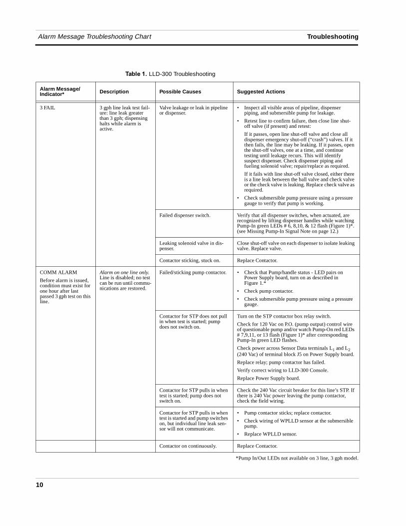
Table 1 lists LLD-300 alarm messages and some suggested corrective procedures.
When measuring the pressure in the line for comparison with pressure transducer readings, always install the pressure gauge DOWNSTREAM of the Check Valve (for example, at the dispenser emergency shut-off valve). DO NOT measure pressure at the pump head.
LLD-300 Alarms Result
Refer To Troubleshooting
Chart
3 FAIL Flashing Red LED, beeper starts, will shut down line page 10
2 FAIL Flashing Red LED, beeper starts, will shut down line if programmed to do so page 12
1 FAIL Flashing Red LED, beeper starts, will shut down line if programmed to do so page 12
COMM ALARM Flashing Red LED, beeper, will shut down line page 10
CONT PMP ALM Flashing Red LED, beeper starts page 11
MONTHLY WARN Red LED lights page 11
SHUTDOWN (not displayed
RS-232 output - posted when one of the above alarms occurs n/a
Important ☞
Alarm Message Troubleshooting Chart Troubleshooting
10
��!��� ��LLD-300 Troubleshooting
Alarm Message/Indicator* Description Possible Causes Suggested Actions
3 FAIL 3 gph line leak test fail-ure: line leak greater than 3 gph; dispensing halts while alarm is active.
Valve leakage or leak in pipeline or dispenser.
• Inspect all visible areas of pipeline, dispenser piping, and submersible pump for leakage.
• Retest line to confirm failure, then close line shut-off valve (if present) and retest:
If it passes, open line shut-off valve and close all dispenser emergency shut-off (“crash”) valves. If it then fails, the line may be leaking. If it passes, open the shut-off valves, one at a time, and continue testing until leakage recurs. This will identify suspect dispenser. Check dispenser piping and fueling solenoid valve; repair/replace as required.
If it fails with line shut-off valve closed, either there is a line leak between the ball valve and check valve or the check valve is leaking. Replace check valve as required.
• Check submersible pump pressure using a pressure gauge to verify that pump is working.
Failed dispenser switch. Verify that all dispenser switches, when actuated, are recognized by lifting dispenser handles while watching Pump-In green LEDs # 6, 8,10, & 12 flash (Figure 1)*. (see Missing Pump-In Signal Note on page 12.)
Leaking solenoid valve in dis-penser.
Close shut-off valve on each dispenser to isolate leaking valve. Replace valve.
Contactor sticking, stuck on. Replace Contactor.
COMM ALARM
Before alarm is issued, condition must exist for one hour after last passed 3 gph test on this line.
Alarm on one line only. Line is disabled; no test can be run until commu-nications are restored.
Failed/sticking pump contactor. • Check that Pump/handle status - LED pairs on Power Supply board, turn on as described in Figure 1.*
• Check pump contactor.
• Check submersible pump pressure using a pressure gauge.
Contactor for STP does not pull in when test is started; pump does not switch on.
Turn on the STP contactor box relay switch.
Check for 120 Vac on P.O. (pump output) control wire of questionable pump and/or watch Pump-On red LEDs # 7,9,11, or 13 flash (Figure 1)* after corresponding Pump-In green LED flashes.
Check power across Sensor Data terminals L1 and L2 (240 Vac) of terminal block J5 on Power Supply board.
Replace relay; pump contactor has failed.
Verify correct wiring to LLD-300 Console.
Replace Power Supply board.
Contactor for STP pulls in when test is started; pump does not switch on.
Check the 240 Vac circuit breaker for this line’s STP. If there is 240 Vac power leaving the pump contactor, check the field wiring.
Contactor for STP pulls in when test is started and pump switches on, but individual line leak sen-sor will not communicate.
• Pump contactor sticks; replace contactor.
• Check wiring of WPLLD sensor at the submersible pump.
• Replace WPLLD sensor.
Contactor on continuously. Replace Contactor.
*Pump In/Out LEDs not available on 3 line, 3 gph model.
Troubleshooting Alarm Message Troubleshooting Chart
11
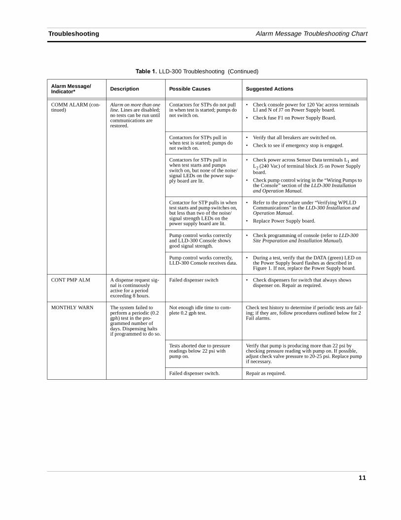
COMM ALARM (con-tinued)
Alarm on more than one line. Lines are disabled; no tests can be run until communications are restored.
Contactors for STPs do not pull in when test is started; pumps do not switch on.
• Check console power for 120 Vac across terminals Ll and N of J7 on Power Supply board.
• Check fuse F1 on Power Supply Board.
Contactors for STPs pull in when test is started; pumps do not switch on.
• Verify that all breakers are switched on.
• Check to see if emergency stop is engaged.
Contactors for STPs pull in when test starts and pumps switch on, but none of the noise/signal LEDs on the power sup-ply board are lit.
• Check power across Sensor Data terminals L1 and L2 (240 Vac) of terminal block J5 on Power Supply board.
• Check pump control wiring in the “Wiring Pumps to the Console” section of the LLD-300 Installation and Operation Manual.
Contactor for STP pulls in when test starts and pump switches on, but less than two of the noise/signal strength LEDs on the power supply board are lit.
• Refer to the procedure under “Verifying WPLLD Communications” in the LLD-300 Installation and Operation Manual.
• Replace Power Supply board.
Pump control works correctly and LLD-300 Console shows good signal strength.
• Check programming of console (refer to LLD-300 Site Preparation and Installation Manual).
Pump control works correctly, LLD-300 Console receives data.
• During a test, verify that the DATA (green) LED on the Power Supply board flashes as described in Figure 1. If not, replace the Power Supply board.
CONT PMP ALM A dispense request sig-nal is continuously active for a period exceeding 8 hours.
Failed dispenser switch • Check dispensers for switch that always shows dispenser on. Repair as required.
MONTHLY WARN The system failed to perform a periodic (0.2 gph) test in the pro-grammed number of days. Dispensing halts if programmed to do so.
Not enough idle time to com-plete 0.2 gph test.
Check test history to determine if periodic tests are fail-ing; if they are, follow procedures outlined below for 2 Fail alarms.
Tests aborted due to pressure readings below 22 psi with pump on.
Verify that pump is producing more than 22 psi by checking pressure reading with pump on. If possible, adjust check valve pressure to 20-25 psi. Replace pump if necessary.
Failed dispenser switch. Repair as required.
��!��� ��LLD-300 Troubleshooting (Continued)
Alarm Message/Indicator* Description Possible Causes Suggested Actions
Alarm Message Troubleshooting Chart Troubleshooting
12
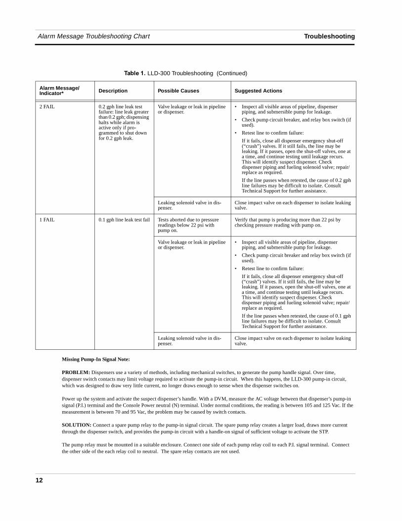
Missing Pump-In Signal Note:
PROBLEM: Dispensers use a variety of methods, including mechanical switches, to generate the pump handle signal. Over time, dispenser switch contacts may limit voltage required to activate the pump-in circuit. When this happens, the LLD-300 pump-in circuit, which was designed to draw very little current, no longer draws enough to sense when the dispenser switches on.
Power up the system and activate the suspect dispenser’s handle. With a DVM, measure the AC voltage between that dispenser’s pump-in signal (P.I.) terminal and the Console Power neutral (N) terminal. Under normal conditions, the reading is between 105 and 125 Vac. If the measurement is between 70 and 95 Vac, the problem may be caused by switch contacts.
SOLUTION: Connect a spare pump relay to the pump-in signal circuit. The spare pump relay creates a larger load, draws more current through the dispenser switch, and provides the pump-in circuit with a handle-on signal of sufficient voltage to activate the STP.
The pump relay must be mounted in a suitable enclosure. Connect one side of each pump relay coil to each P.I. signal terminal. Connect the other side of the each relay coil to neutral. The spare relay contacts are not used.
2 FAIL 0.2 gph line leak test failure: line leak greater than 0.2 gph; dispensing halts while alarm is active only if pro-grammed to shut down for 0.2 gph leak.
Valve leakage or leak in pipeline or dispenser.
• Inspect all visible areas of pipeline, dispenser piping, and submersible pump for leakage.
• Check pump circuit breaker, and relay box switch (if used).
• Retest line to confirm failure:
If it fails, close all dispenser emergency shut-off (“crash”) valves. If it still fails, the line may be leaking. If it passes, open the shut-off valves, one at a time, and continue testing until leakage recurs. This will identify suspect dispenser. Check dispenser piping and fueling solenoid valve; repair/replace as required.
If the line passes when retested, the cause of 0.2 gph line failures may be difficult to isolate. Consult Technical Support for further assistance.
Leaking solenoid valve in dis-penser.
Close impact valve on each dispenser to isolate leaking valve.
1 FAIL 0.1 gph line leak test fail Tests aborted due to pressure readings below 22 psi with pump on.
Verify that pump is producing more than 22 psi by checking pressure reading with pump on.
Valve leakage or leak in pipeline or dispenser.
• Inspect all visible areas of pipeline, dispenser piping, and submersible pump for leakage.
• Check pump circuit breaker and relay box switch (if used).
• Retest line to confirm failure:
If it fails, close all dispenser emergency shut-off (“crash”) valves. If it still fails, the line may be leaking. If it passes, open the shut-off valves, one at a time, and continue testing until leakage recurs. This will identify suspect dispenser. Check dispenser piping and fueling solenoid valve; repair/replace as required.
If the line passes when retested, the cause of 0.1 gph line failures may be difficult to isolate. Consult Technical Support for further assistance.
Leaking solenoid valve in dis-penser.
Close impact valve on each dispenser to isolate leaking valve.
��!��� ��LLD-300 Troubleshooting (Continued)
Alarm Message/Indicator* Description Possible Causes Suggested Actions
Troubleshooting PROM Chip Replacement (Software Upgrade)
13
PROM Chip Replacement (Software Upgrade)
The PROM chip is replaced when a software upgrade is installed. This procedure requires that you perform a RAM clear.
1. If possible, record the current setup information. Turn off power to the system.
2. Open the front door of the console. The CPU board is installed in the door. Disconnect the CPU board cable from the Power Supply board. Remove the CPU board following the instructions in “CPU Board” on page 6.
3. Locate the PROM chip on the board [Figure 2].
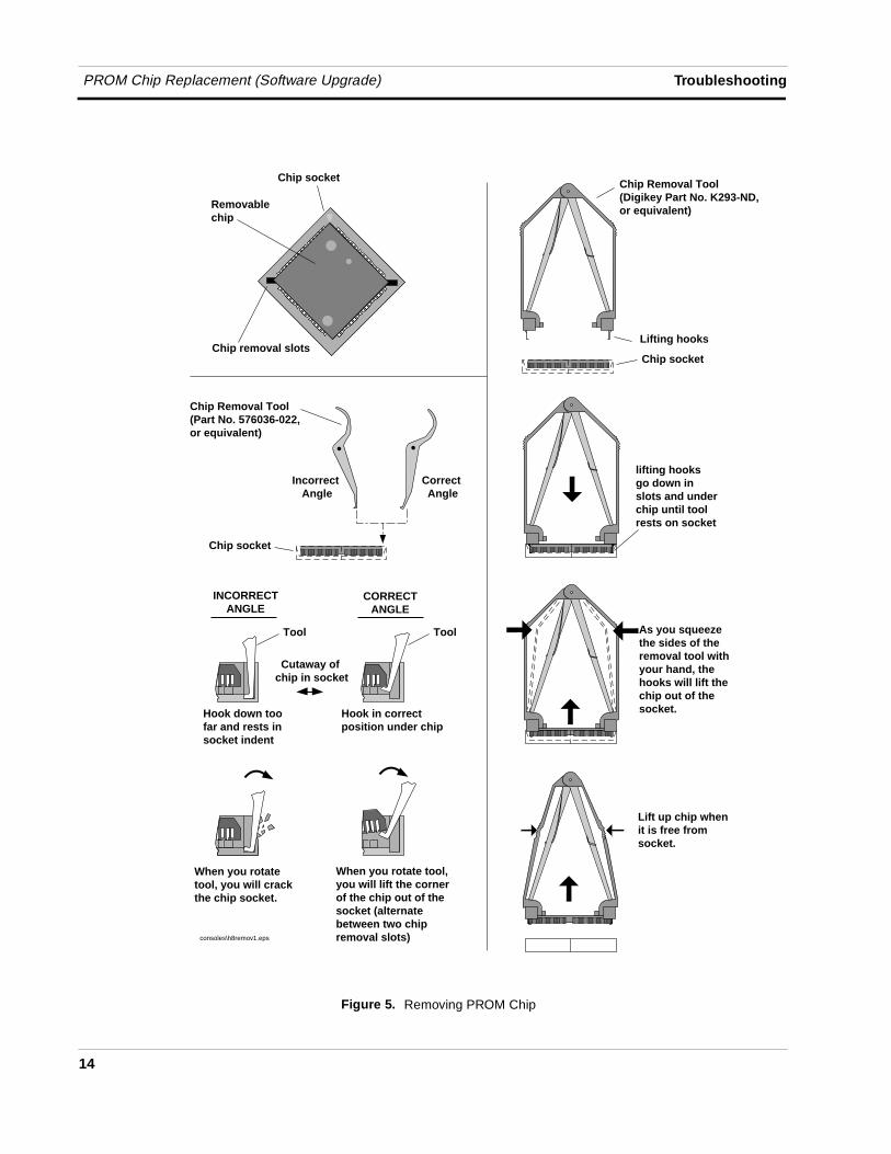
4. Remove the PROM chip following instructions in Figure 5.
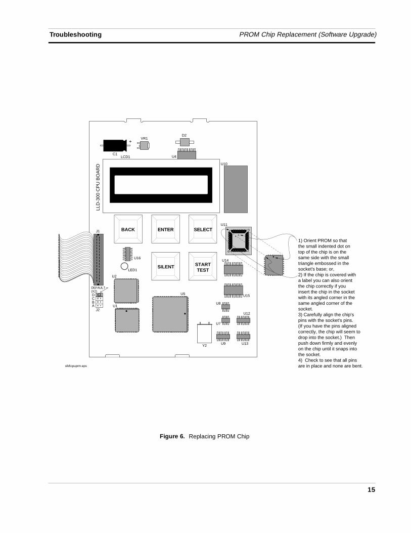
5. Replace the PROM chip following instructions in Figure 6.
6. Replace the CPU board in the front door of the LLD-300. Connect the CPU board cable to J3 on the Power Supply board.
7. Follow the instructions in “Cold Boot Procedure”.
OFF
PROM Chip Replacement (Software Upgrade) Troubleshooting
14
Figure 5. Removing PROM Chip
As you squeeze the sides of theremoval tool with your hand, thehooks will lift thechip out of the socket.
Lifting hooks
lifting hooks go down in slots and under chip until toolrests on socket
Chip Removal Tool(Digikey Part No. K293-ND,or equivalent)
Chip socket
Removablechip
Chip removal slots
Lift up chip whenit is free from socket.
Chip socket
consoles\h8remov1.eps
Chip socket
Incorrect Angle
Correct Angle
INCORRECTANGLE
CORRECTANGLE
Hook down too far and rests in socket indent
Hook in correctposition under chip
When you rotatetool, you will crackthe chip socket.
When you rotate tool, you will lift the corner of the chip out of thesocket (alternatebetween two chipremoval slots)
Chip Removal Tool(Part No. 576036-022, or equivalent)
Tool Tool
Cutaway of chip in socket
Troubleshooting PROM Chip Replacement (Software Upgrade)
15
Figure 6. Replacing PROM Chip
LCD1
BACK ENTER SELECT
SILENT STARTTEST
U10
C1
+
U11
Y2
U5
U1
J1
LED1
U16
VR1D2
U4
U14
U15
U8
U7
U12
U13U9
U2
LLD
-300
CP
U B
OA
RD
DEFAULT(X2)DCBA
J2
1) Orient PROM so thatthe small indented dot ontop of the chip is on thesame side with the smalltriangle embossed in thesocket's base; or, 2) If the chip is covered with a label you can also orient the chip correctly if youinsert the chip in the socketwith its angled corner in the same angled corner of the socket. 3) Carefully align the chip's pins with the socket's pins. (If you have the pins aligned correctly, the chip will seem to drop into the socket.) Then push down firmly and evenly on the chip until it snaps into the socket. 4) Check to see that all pins are in place and none are bent.
slld\cpuprm.eps
Cold Boot Procedure Troubleshooting
16
Replacing the CPU BoardThe CPU board must be replaced if:
❑ If one of the system self-tests fails during a warm boot [page 9] or a cold boot;
❑ The display contains garbled messages and the voltage between the GND and 8V test points [Figure 2] on the back of the CPU board is within 7 - 9 Vdc; or,
❑ The voltage between the GND and 5V test points [Figure 2] on the back of the CPU board is not within 4.75 - 5.25 Vdc.
1. Turn off power to the system. Disconnect the CPU cable from the Power Supply board.
2. The CPU board snaps securely into place in the door of the console without the use of screws. There are two tabs on the top of the board that fit into two slots in the top edge of the door. The bottom of the CPU board snaps in place between two pairs of detents protruding from the bottom edge of the door. The CPU board is removed by inserting a straight-slot screwdriver into one of the two indents on the bottom of the board and then gently prying against the door until the board clears the upper detents, then rotating the board up slightly and toward you to clear the top tabs from the slots in the door.
3. Replace the CPU board reversing the above steps.
4. Perform a cold boot of the system.
Cold Boot Procedure
A cold boot of the system is required after installing a software upgrade, after replacing the CPU board, or if you want to clear console historical data or setup parameters.
Turn off power to the console. Open the console front door and locate the RAM clear jumper J2 [Figure 1]. Move the jumper to pins 2 and 3. Turn on power to the console. The display will read RAM CLEAR, then begin a cold boot while displaying these status messages:
Test Passed Test Failed Action (If Failed)
RAM TEST - OK RAM FAIL Replace CPU boardROM TEST - OK ROM FAIL “ “ “COLD BOOTEEPROM TEST - OK EEPROM FAIL “ “ “CALCLK - OK* CALCLK FAIL “ “ “NVRAM TEST - OK* NVRAM FAIL “ “ “STARTUP COMPLETE
*These self-tests occur in 0.2 and 0.1 gph models only
If you leave the jumper in position 2-3, the console will continue to cycle through the RAM CLEAR and cold boot messages. Turn off power to the console. Move Jumper (J2) back to the 1-2 position. Turn on power to the console. The console will run the
OFF
OFF
OFF
Troubleshooting Cold Boot Procedure
17
cold boot procedure and return to the Main Screen (MM/DD/YY HH:MM or All LINES NORMAL depending on which LLD-300 model you have).
Reprogram the system following the setup procedure in the LLD-300 Installation, Setup, and Operation Manual (V-R No. 5776013-546).
When you finish the setup procedure, a 3 gph test must be run on each line before the system becomes operational and the site can pump fuel.
Return to the Main Screen and press the START TEST to button to initiate the line leak tests. A 3 gph test will automatically run on all of the lines. If the LLD-300 model has the 0.2 gph option, a 0.2 gph test will automatically follow the 3 gph test. If the LLD-300 model has the 0.1 gph option, and you press and hold the START TEST key for 3 seconds (you will hear the beeper), the 0.2 gph test will be followed by a 0.1 gph test.
During the tests the display will read TEST L: 1 2 3 4. As tests for a line are completed, that line’s number will disappear from the screen. When all tests are complete, the display will either return to the Main Screen or display a test failed alarm.
Overriding the Automatic 0.2 gph TestThe time required to run a 3 gph test is approximately 45 seconds. The time required to run a 0.2 gph test is at least 30 minutes (the time required to run a 0.1 gph test is at least 30 minutes also). If there is an urgent need to get the site up and running, you can run the mandatory 3 gph test on all lines and then manually override the 0.2 gph test on the lines.
In this discussion, the LLD-300 is assumed to be monitoring 4 lines and have at least 0.2 gph test capability.
1. Perform the cold boot [page 40] and programming procedures[page 44] in the LLD-300 Installation, Setup, and Operation Manual (V-R No. 5776013-546).
2. With the Main Screen displayed, press the START TEST key. The display will read TEST L: 1 2 3 4. Within 8 seconds all lines will have started the 3 gph test and within another 45 seconds, all lines should have passed their 3 gph tests.
3. Press ENTER once then press SELECT until the display reads L1 DIAGNOSTICS; press ENTER and the display reads L1 E1 T2 P0 (or P1) H0. T2 indicates the test underway is a 0.2 gph test and E1 indicates the line is enabled (the 3 gph test passed). Ensuring that the dispenser handles are in their cradles (H0), press START TEST to turn off the 0.2 gph test in progress on Line 1 (the display will now read L1 E1 T0 P0 (or P1) H0.
4. Press BACK and the display reads L1 DIAGNOSTICS. Press SELECT and the display reads L2 DIAGNOSTICS. Following the procedure in steps 3 and 4, to abort the 0.2 gph tests on the remaining lines.
5. Now that all lines have been enabled (E1), you can return to the Main Screen.
Important ☞
Cold Boot Procedure Troubleshooting
18
The Override test procedure can also be used to abort any 0.2 gph or 0.1 gph test in progress (T2 or T1). Just go to step 3 above, press SELECT until the particular line’s diagnostic screen is displayed, press ENTER then START TEST to stop the test (T0).
Replacing the Power Supply BoardThe Power Supply board must be replaced when:
❑ WPLLD sensor data is not being processed
❑ Dispenser inputs are received but not processed
❑ Pump contactors are not being turned on
❑ The voltage between the GND and 8V test points [Figure 2] on the back of the CPU board is less than 7 Vdc.
1. Turn off power to the system.
2. Disconnect the CPU cable from the Power Supply board.
3. Tag and disconnect wiring inputs to the Power Supply board.
4. The Power Supply board is supported on the bottom of the board by two tabs that are inserted into slots in the bottom of the console, and supported on its two sides by detents that extend out from the sides of the console, and on the top by two PEM studs attached to the base of the console.
The board is secured by two T-15 Torx screws on either side of the transformer which screw into the two PEM studs. If the LLD-300 has the optional RS-232 seri-al interface, the two screw locks which go through the bottom of the console into the DB9 connector must be taken out before removing the board.
After removing the Torx screws (and screw locks), slowly lift up on the board hold-ing the transformer, until the lower tabs on the board clear the slots in the bottom of the console, then continue to lift the board out.
5. Replace the board by reversing the above steps.
6. Turn on power to the system.Follow the instructions in “Powering Up The System”, beginning on page 40 of the Installation, Seetup, and Operation manual (V-R no. 577013-546).
Fuse F1If the 120 Vac console power circuit breaker is on, but the display doesn’t come on, check console fuse F1 [Figure 1]. Turn off power, test fuse, replace if necessary.
OFF
OFF
Troubleshooting Using the Diagnostic Menu
19
Visually Checking System OperationYou can visually check various LEDs on the Power Supply board to see if the system is correctly processing, dispenser inputs, pump commands, sensor messages, and scheduling tests.
1. Turn off power to the system. Check that all wiring connections are correct between the sensors, dispensers, and console and that the system setup procedure was performed (ref. V-R manual 577013-546).
2. Open the console front door. Locate the Pump/handle status LED pairs for each line (LED 6 handle & LED 7 pump on for pump 1, etc. - these LEDs not available on 3 line, 3 gph only model). Locate the Noise/signal strength red LEDs (4). Locate the DATA and DIAG LEDs.
3. Turn on power to the system.
4. 3 Line, 3 gph only model
Have an assistant go to any dispenser on line 1. Have the assistant lift the handle. In about 10 seconds that pump’s sensor will transmit its first message (approxi-mately 0.5 seconds long), causing some or all of the Noise/signal strength red LEDs and the green DATA LED to flash as the message is received. The red DIAG LED flashes once if messagewas successfully received by the software.
All other Models
Have an assistant go to any dispenser on line 1. While watching line 1’s Pump/han-dle status LEDs, have the assistant lift the handle. The green handle status (P.I.) LED (LED 6) will turn on, followed within 2 seconds by the red Pump- on (P.O.) LED (LED 7) turning on. Eight seconds later that pump’s sensor will transmit its first message (approximately 0.5 seconds long), causing some or all of the Noise/signal strength red LEDs and the green DATA LED to flash as the message is re-ceived. The red DIAG LED flashes once if messagewas successfully received by the software.
5. You can repeat this same procedure for each of the lines to visually observe the proper operation of the entire system.
Using the Diagnostic Menu
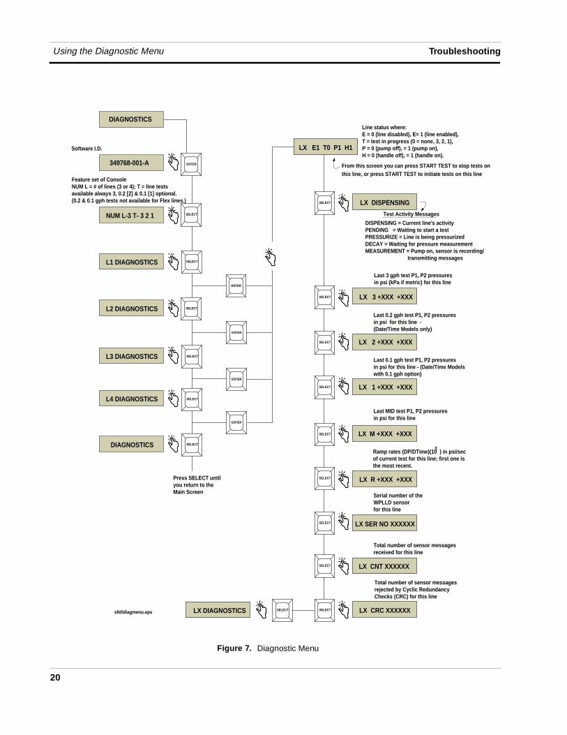
The Diagnostic Menu is accessed from the front panel of the console. From the Top Level menu press SELECT until the display reads DIAGNOSTICS [Figure 7].
Units of measurement shown Figure 7 are in U.S. units. Metric equivalents (e.g., kPa instead of psi) will appear if metric units are selected during system setup.
OFF
Using the Diagnostic Menu Troubleshooting
20
Figure 7. Diagnostic Menu
NUM L-3 T- 3 2 1 SELECT
L1 DIAGNOSTICS SELECT
L2 DIAGNOSTICS SELECT
L3 DIAGNOSTICS SELECT
L4 DIAGNOSTICS SELECT
LX E1 T0 P1 H1
ENTER
ENTER
ENTER
ENTER
SELECT
LX 3 +XXX +XXX
ENTER
LX 2 +XXX +XXXSELECT
LX 1 +XXX +XXXSELECT
LX M +XXX +XXXSELECT
LX R +XXX +XXXSELECT
LX SER NO XXXXXXSELECT
LX CNT XXXXXXSELECT
LX CRC XXXXXXLX DIAGNOSTICS
DIAGNOSTICS
slld\diagmenu.eps
Software I.D.
Feature set of ConsoleNUM L = # of lines (3 or 4); T = line tests available always 3, 0.2 [2] & 0.1 [1] optional. (0.2 & 0.1 gph tests not available for Flex lines.)
Line status where: E = 0 (line disabled), E= 1 (line enabled),T = test in progress (0 = none, 3, 2, 1),P = 0 (pump off), = 1 (pump on),H = 0 (handle off), = 1 (handle on).
LX DISPENSING SELECT
SELECT
Test Activity Messages
Last 3 gph test P1, P2 pressuresin psi (kPa if metric) for this line
Last 0.2 gph test P1, P2 pressuresin psi for this line - (Date/Time Models only)
Last 0.1 gph test P1, P2 pressuresin psi for this line - (Date/Time Modelswith 0.1 gph option)
Last MID test P1, P2 pressuresin psi for this line
Ramp rates (DP/DTime)(10 ) in psi/secof current test for this line; first one is the most recent.
Serial number of theWPLLD sensorfor this line
Total number of sensor messagesreceived for this line
Total number of sensor messagesrejected by Cyclic Redundancy Checks (CRC) for this line
Press SELECT untilyou return to theMain Screen
From this screen you can press START TEST to stop tests on this line, or press START TEST to initiate tests on this line
3
DISPENSING = Current line's activityPENDING = Waiting to start a testPRESSURIZE = Line is being pressurizedDECAY = Waiting for pressure measurementMEASUREMENT = Pump on, sensor is recording/ transmitting messages
SELECT SELECT
DIAGNOSTICS
349768-001-A
21
LLD-300 System Specifications
Physical Specifications
Console❑ Width (door closed): 7.62” (door open 9.62”)
❑ Height: 6.75”
❑ Depth (door closed): 2.62” (door open 9”)
❑ Weight: 3.5 lbs.
❑ Two PC boards in console: CPU (in door) and Power Supply (in unit)
WPLLD Sensor❑ Pressure range: 0 - 70 psig
❑ Output: 4-20 mA
❑ Repeatability: ±0.5% F.S., at constant temperature and pressure: includes hysteresis
❑ Accuracy: ±0.5 psi, ±5% of reading at room temperature
❑ Operating Temperature: -40 to +150°F
❑ Storage Temperature: -40 to +165°F
❑ Humidity: 100% RH, non-condensing
❑ Proof Pressure: 200 psi
❑ Burst Pressure: 250 psi
❑ Immersion: 8 feet of water or gasoline
SwiftCheck Valve (if used)❑ Operating Pressure: 0 - 50 psig
❑ Proof pressure: 100 psig
❑ Burst pressure: 250 psig
Environmental Specifications
❑ Console storage and operation: indoor, climate controlled
Electrical Specifications
❑ Console operating voltage: 120 Vac, 2 A max.
Software Specifications LLD-300 System Specifications
22
Software Specifications
❑ Four system interface modes, via front panel keys: Operating (Top Level), History, Setup, Diagnostic
❑ System, test, and alarm messages posted to front panel display and to optional RS-232 serial interface connector
❑ System, test, and alarm messages and all histories (0.2 gph and 0.1 gph models) are stored in battery-backed RAM
❑ System Setup information and line test pass/fail status are stored in EEPROM
❑ System software in a snap-in PROM chip
❑ RAM clear jumper
RS-232 Serial Interface (Optional)
❑ Connector: DB9
❑ Settings: 1200 baud, 7 data bits, Odd parity, 1 stop bit
❑ Veeder-Root RS-232 command protocol format (includes some RS-232 serial commands that are only for the LLD-300)
❑ The complete compliance and diagnostic history lists will be available through the RS-232 serial interface.
Signal Input Specifications
❑ Pump In (P.I.): 120 Vac, 0.1 A max. (from dispenser)
❑ Sensor Data: 240 Vac, 0.125 A (pump ac)
Signal Output Specifications
❑ Pump Output (P.O.): 120 Vac, 0.4 A (to pump contactor)
CAUTION: Pump contactors with coil resistance of less than 275 ohms must be driven by an isolation relay. Failure to do so will result in damage to the LLD-300.
❑ Ext. Out DC Switch: rating 5-15 Vdc, 0.15 A
Front Panel User Interface
❑ 16-character, single line, LCD display
❑ Visible annunciator (bi-color LED)
❑ Green - all functions normal
❑ Flashing red - line leak alarm active
LLD-300 System Specifications Leak Testing
23
❑ Steady red - warning
❑ Push buttons
❑ SELECT
❑ ENTER
❑ BACK
❑ SILENCE
❑ START TEST
❑ Audible annunciator: internal beeper
Leak Testing
❑ Tests performed: 3 gph (gross), optional 0.2 gph (periodic), and optional 0.1 gph (annual)
❑ Tests initiated automatically or manually
❑ Single line tests only (tests on dual or manifolded lines not supported)
❑ Line type: steel or fiberglass
❑ Line length: steel 30 - 499 feet; glass 30 - 350 feet
24
RS-232 Serial Interface - Optional
Interfacing the LLD-300 Console by RS-232 serial communication is done through the DB9 connector on the bottom of the unit. For more information on the command format, consult Veeder-Root’s Serial Interface Manual (Part No. 576013-635).
DB9 Connector Pin-Outs
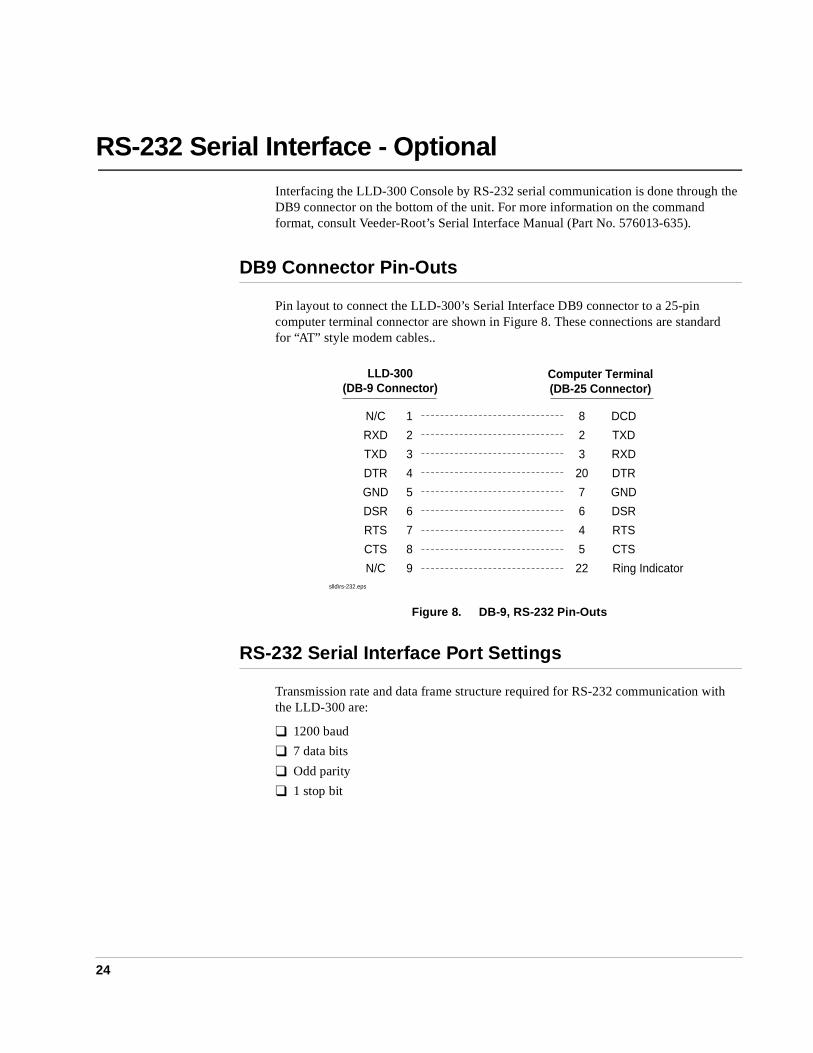
Pin layout to connect the LLD-300’s Serial Interface DB9 connector to a 25-pin computer terminal connector are shown in Figure 8. These connections are standard for “AT” style modem cables..
Figure 8. DB-9, RS-232 Pin-Outs
RS-232 Serial Interface Port Settings
Transmission rate and data frame structure required for RS-232 communication with the LLD-300 are:
❑ 1200 baud
❑ 7 data bits
❑ Odd parity
❑ 1 stop bit
Computer Terminal(DB-25 Connector)
LLD-300(DB-9 Connector)
N/C 1 DCD8
RXD 2 TXD2
TXD 3 RXD3
DTR 4 DTR20
GND 5 GND7
DSR 6 DSR6
RTS 7 RTS4
CTS 8 CTS5
N/C 9 Ring Indicator22slld\rs-232.eps
RS-232 Serial Interface - Optional RS-232 Serial Commands
25
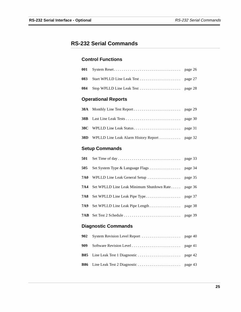
RS-232 Serial Commands
Control Functions
001 System Reset . . . . . . . . . . . . . . . . . . . . . . . . . . . . . . . . . . page 26
083 Start WPLLD Line Leak Test . . . . . . . . . . . . . . . . . . . . . page 27
084 Stop WPLLD Line Leak Test . . . . . . . . . . . . . . . . . . . . . page 28
Operational Reports
38A Monthly Line Test Report . . . . . . . . . . . . . . . . . . . . . . . . page 29
38B Last Line Leak Tests . . . . . . . . . . . . . . . . . . . . . . . . . . . . page 30
38C WPLLD Line Leak Status . . . . . . . . . . . . . . . . . . . . . . . . page 31
38D WPLLD Line Leak Alarm History Report . . . . . . . . . . . page 32
Setup Commands
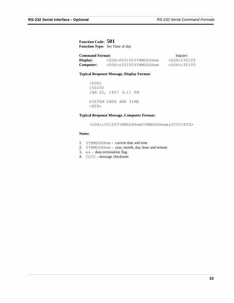
501 Set Time of day . . . . . . . . . . . . . . . . . . . . . . . . . . . . . . . . page 33
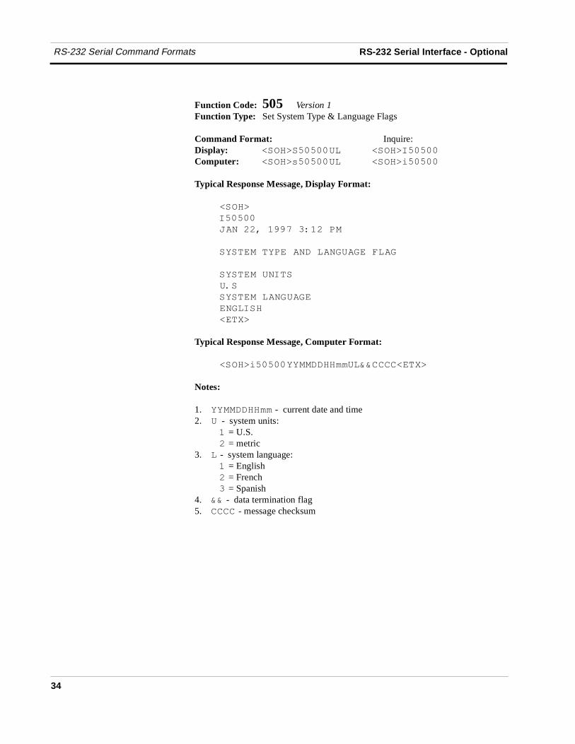
505 Set System Type & Language Flags . . . . . . . . . . . . . . . . page 34
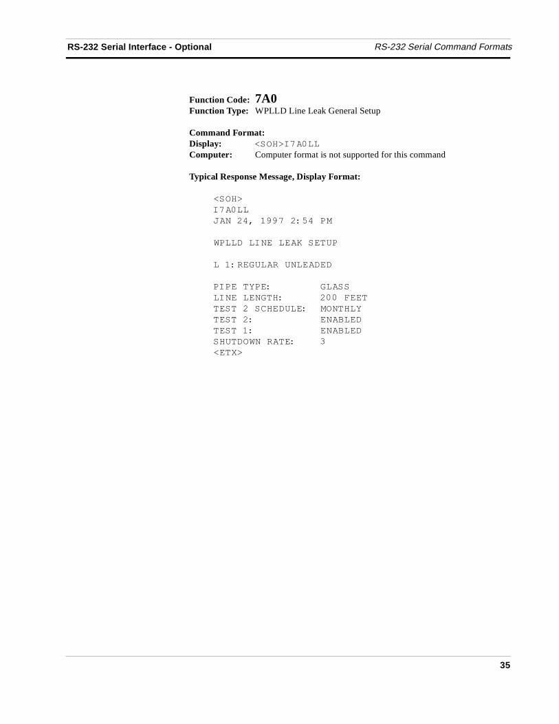
7A0 WPLLD Line Leak General Setup . . . . . . . . . . . . . . . . . page 35
7A4 Set WPLLD Line Leak Minimum Shutdown Rate . . . . . page 36
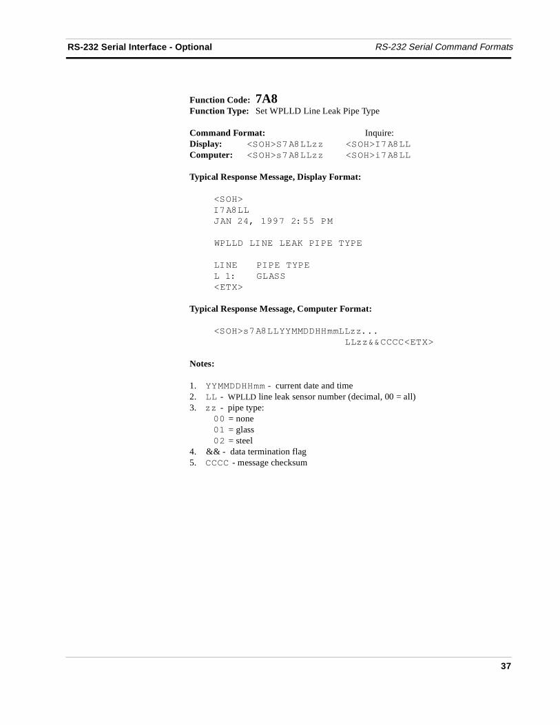
7A8 Set WPLLD Line Leak Pipe Type. . . . . . . . . . . . . . . . . . page 37
7A9 Set WPLLD Line Leak Pipe Length . . . . . . . . . . . . . . . . page 38
7AB Set Test 2 Schedule . . . . . . . . . . . . . . . . . . . . . . . . . . . . . page 39
Diagnostic Commands
902 System Revision Level Report . . . . . . . . . . . . . . . . . . . . page 40
909 Software Revision Level . . . . . . . . . . . . . . . . . . . . . . . . . page 41
B85 Line Leak Test 1 Diagnostic . . . . . . . . . . . . . . . . . . . . . . page 42
B86 Line Leak Test 2 Diagnostic . . . . . . . . . . . . . . . . . . . . . . page 43
RS-232 Serial Command Formats RS-232 Serial Interface - Optional
26
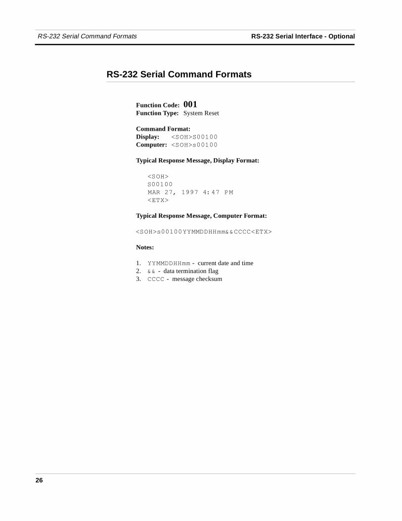
RS-232 Serial Command Formats
Function Code: 001Function Type: System Reset
Command Format:Display: �����������
Computer: �����������
Typical Response Message, Display Format:
�����
������
�� ��������������
�����
Typical Response Message, Computer Format:
������������������������������
Notes:
1. �������� - current date and time2. �� - data termination flag3. ���� - message checksum
RS-232 Serial Interface - Optional RS-232 Serial Command Formats
27
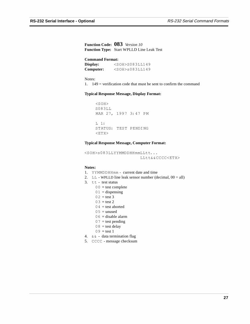
Function Code: 083 Version 10Function Type: Start WPLLD Line Leak Test
Command Format:Display: ��������������
Computer: ��������������
Notes:1. 149 = verification code that must be sent to confirm the command
Typical Response Message, Display Format:
�����
������
�� ��������������
����
�������������� �! "
�����
Typical Response Message, Computer Format:
���������������������##$$$
��##�����������
Notes:1. �������� - current date and time2. �� - WPLLD line leak sensor number (decimal, 00 = all)3. ## - test status
�� = test complete�� = dispensing� = test 3 �� = test 2�� = test aborted�% = unused�& = disable alarm�� = test pending�� = test delay�� = test 1
4. �� - data termination flag5. ���� - message checksum
RS-232 Serial Command Formats RS-232 Serial Interface - Optional
28
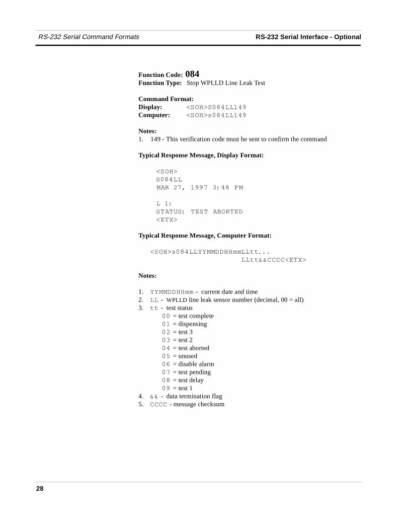
Function Code: 084Function Type: Stop WPLLD Line Leak Test
Command Format:Display: ��������������
Computer: ��������������
Notes:1. 149 - This verification code must be sent to confirm the command
Typical Response Message, Display Format:
�����
������
�� ��������������
�����
������������'�����
�����
Typical Response Message, Computer Format:
���������������������##$$$
��##�����������
Notes:
1. �������� - current date and time2. �� - WPLLD line leak sensor number (decimal, 00 = all)3. ## - test status
�� = test complete�� = dispensing� = test 3�� = test 2�� = test aborted�% = unused�& = disable alarm�� = test pending�� = test delay�� = test 1
4. �� - data termination flag5. ���� - message checksum
RS-232 Serial Interface - Optional RS-232 Serial Command Formats
29
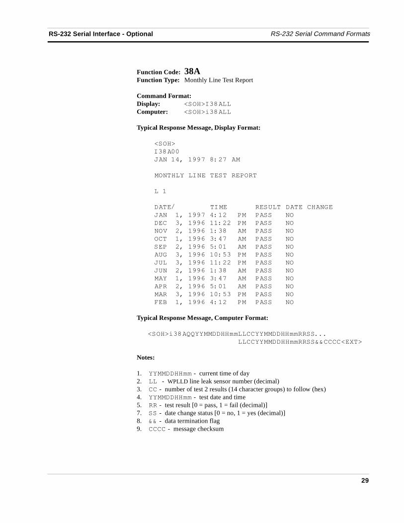
Function Code: 38AFunction Type: Monthly Line Test Report
Command Format:Display: �����!����
Computer: �����(����
Typical Response Message, Display Format:
�����
!����
) ������������ ��
� ������! �������������
���
���* �!� ������������� "�
) ������������� �� ��� �
�����������&���� �� ��� �
�+�� �����&����� ��� �
�����������&����� � ��� �
����� �����&�%��� ��� �
�"��������&����%� �� ���� �
)����������&���� � ��� �
)� �� �����&����� ��� �
���������&����� � ���� �
���� �����&�%��� ��� �
���������&����%� � ��� �
,�'��������&���� � ���� �
Typical Response Message, Computer Format:
�����(��--������������������������$$$
���������������������������
Notes:
1. �������� - current time of day2. ���- WPLLD line leak sensor number (decimal)3. �� - number of test 2 results (14 character groups) to follow (hex)4. �������� - test date and time5. �� - test result [0 = pass, 1 = fail (decimal)]7. �� - date change status [0 = no, 1 = yes (decimal)]8. �� - data termination flag9. ���� - message checksum
RS-232 Serial Command Formats RS-232 Serial Interface - Optional
30
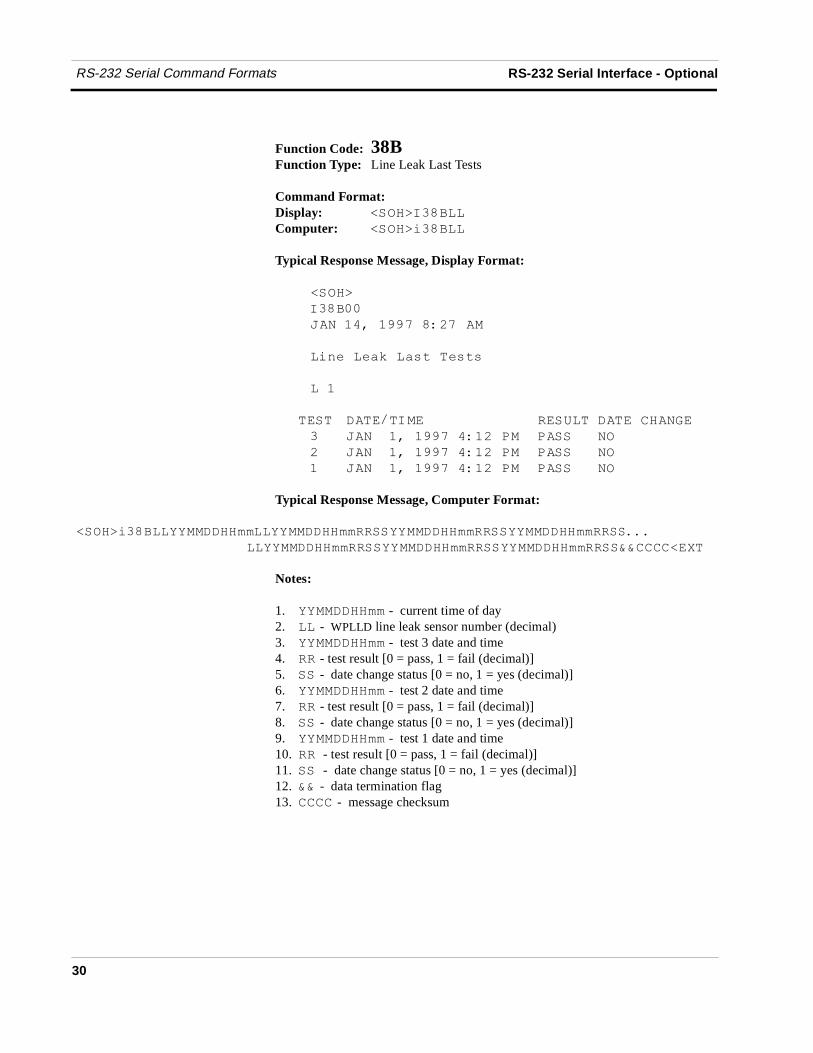
Function Code: 38BFunction Type: Line Leak Last Tests
Command Format:Display: �����!��'��
Computer: �����(��'��
Typical Response Message, Display Format:
�����
!��'��
) ������������ ��
�(./��/01��0�#��/�#�
���
���� ���*�!� ������ ������ "�
�� ) ������������� �� ���� �
� ) ������������� �� ���� �
�� ) ������������� �� ��� �
Typical Response Message, Computer Format:
������������ �������� ������������ ������������ �����������
���� ������������ ������������ ������������������
Notes:
1. �������� - current time of day2. �� - WPLLD line leak sensor number (decimal)3. �������� - test 3 date and time4. �� - test result [0 = pass, 1 = fail (decimal)]5. �� - date change status [0 = no, 1 = yes (decimal)]6. �������� - test 2 date and time7. �� - test result [0 = pass, 1 = fail (decimal)]8. �� - date change status [0 = no, 1 = yes (decimal)]9. �������� - test 1 date and time10. �� - test result [0 = pass, 1 = fail (decimal)]11. �� - date change status [0 = no, 1 = yes (decimal)]12. �� - data termination flag13. ���� - message checksum
RS-232 Serial Interface - Optional RS-232 Serial Command Formats
31
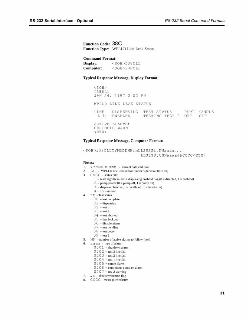
Function Code: 38CFunction Type: WPLLD Line Leak Status
Command Format:Display: �����!�����
Computer: �����(�����
Typical Response Message, Display Format:
�����!��&��) � �������� �% ��
2������! ����3������
�! � �!��� �! "������������ ��� � ������� � '������������! "������ �,, �,,
��!+���������!��!��2� �����
Typical Response Message, Computer Format:
�����(�������������������## 0000$$$
� �������## 0000�����������
Notes:1. ���������- current date and time2. ���- WPLLD line leak sensor number (decimal, 00 = all)3. ���� - status bits:
� - least significant bit = dispensing enabled flag (0 = disabled, 1 = enabled) - pump power (0 = pump off, 1 = pump on)� - dispenser handle (0 = handle off, 1 = handle on)�4�& - unused
4. ## - Test status�� = test complete�� = dispensing� = test 3�� = test 2�� = test aborted�% = line lockout�& = disable alarm�� = test pending�� = test delay�� = test 1
5. - number of active alarms to follow (hex)6. 0000 - type of alarm:
���� = shutdown alarm��� = test 3 line fail���� = test 2 line fail���� = test 1 line fail���% = comm alarm���& = continuous pump on alarm���� = test 2 warning
7. �� - data termination flag8. ���� - message checksum
RS-232 Serial Command Formats RS-232 Serial Interface - Optional
32
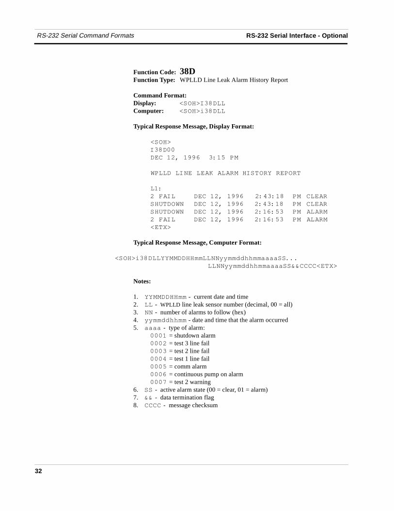
Function Code: 38DFunction Type: WPLLD Line Leak Alarm History Report
Command Format:Display: �����!�����
Computer: �����(�����
Typical Response Message, Display Format:
�����
!�����
����� �����&�����%��
2������! ����3�����!���������������
�����������������������
�,!�� ����� �����& ������ � ����
������2 � ����� �����&�� ������ � ����
������2 � ����� �����&�� ��&�%� � ��
�,!�� ����� �����&�� ��&�%� � ��
�����
Typical Response Message, Computer Format:
�����(��������������� 55��6677��0000��$$$
�� 55��6677��0000�������������
Notes:
1. �������� - current date and time2. �� - WPLLD line leak sensor number (decimal, 00 = all)3. - number of alarms to follow (hex)4. 55��6677�� - date and time that the alarm occurred5. 0000 - type of alarm:
���� = shutdown alarm��� = test 3 line fail���� = test 2 line fail���� = test 1 line fail���% = comm alarm���& = continuous pump on alarm���� = test 2 warning
6. �� - active alarm state (00 = clear, 01 = alarm)7. �� - data termination flag8. ���� - message checksum
RS-232 Serial Interface - Optional RS-232 Serial Command Formats
33
Function Code: 501Function Type: Set Time of day
Command Format: Inquire:Display: ������%������������ �����!%����
Computer: ������%������������ �����(%����
Typical Response Message, Display Format:
�����
!%����
) � �������������
���������� ���!�
�����
Typical Response Message, Computer Format:
�����(%�������������������������������
Notes:
1. �������� - current date and time2. �������� - year, month, day, hour and minute3. �� - data termination flag4. ���� - message checksum
RS-232 Serial Command Formats RS-232 Serial Interface - Optional
34
Function Code: 505 Version 1Function Type: Set System Type & Language Flags
Command Format: Inquire:Display: ������%�%���� �����!%�%��
Computer: ������%�%���� �����(%�%��
Typical Response Message, Display Format:
�����
!%�%��
) � ���������� ��
����������� ��� "�"��,�"
������� !��
�$�
������� "�"�
� "�!��
�����
Typical Response Message, Computer Format:
�����(%�%�����������������������
Notes:
1. �������� - current date and time2. ��- system units:
� = U.S. = metric
3. � - system language:� = English = French� = Spanish
4. �� - data termination flag5. ���� - message checksum
RS-232 Serial Interface - Optional RS-232 Serial Command Formats
35
Function Code: 7A0Function Type: WPLLD Line Leak General Setup
Command Format:Display: �����!����
Computer: Computer format is not supported for this command
Typical Response Message, Display Format:
�����
!����
) � �������� �%���
2������! ����3������
������"����� �����
�!�������� "���
�! ���� "���� ���,���
����� ���������� � ����
����� � � '���
������� � '���
������2 ����� �
�����

RS-232 Serial Command Formats RS-232 Serial Interface - Optional
36
Function Code: 7A4Function Type: WPLLD Line Leak Minimum Shutdown Rate
Command Format: Inquire:Display: ����������88 �����!����
Computer: ����������88 �����(����
Typical Response Message, Display Format:
�����
!����
) � �������� �%%��
2������! ����3�������2 ����
�! ����������2 ����
��������
�����
Typical Response Message, Computer Format:
�����(��������������88$$$
���88�����������
Notes:
1. �������� - current date and time2. �� - WPLLD line leak sensor number (decimal, 00 = all)3. 88 - shutdown rate
�� = test 2� = test 3�� = test 1
4. �� - data termination flag5. ���� - message checksum
RS-232 Serial Interface - Optional RS-232 Serial Command Formats
37
Function Code: 7A8Function Type: Set WPLLD Line Leak Pipe Type
Command Format: Inquire:Display: ����������99 �����!����
Computer: ����������99 �����(����
Typical Response Message, Display Format:
�����
!����
) � �������� �%%��
2������! ����3��!�������
�! � �!�������
���� "���
�����
Typical Response Message, Computer Format:
��������������������99$$$
� ���99�����������
Notes:
1. �������� - current date and time2. �� - WPLLD line leak sensor number (decimal, 00 = all)3. 99 - pipe type:
�� = none�� = glass� = steel
4. && - data termination flag5. ���� - message checksum
RS-232 Serial Command Formats RS-232 Serial Interface - Optional
38
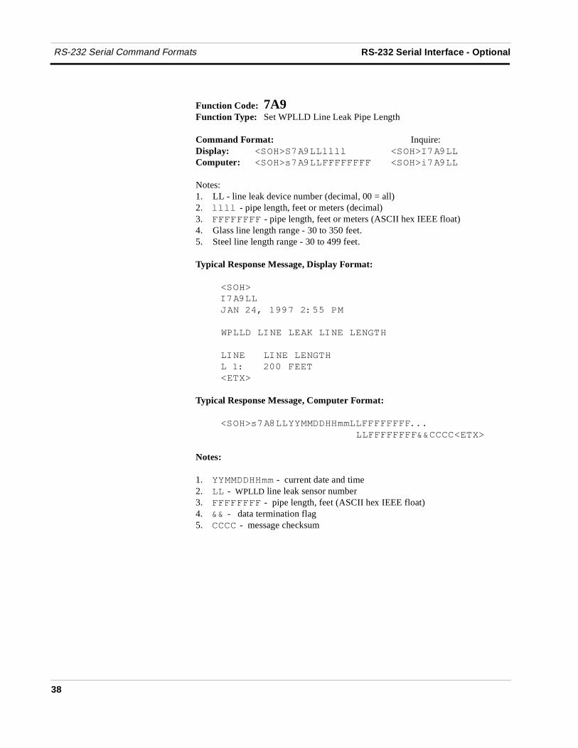
Function Code: 7A9Function Type: Set WPLLD Line Leak Pipe Length
Command Format: Inquire:Display: ����������:::: �����!����
Computer: ����������,,,,,,,, �����(����
Notes:1. LL - line leak device number (decimal, 00 = all)2. :::: - pipe length, feet or meters (decimal)3. ,,,,,,,, - pipe length, feet or meters (ASCII hex IEEE float)4. Glass line length range - 30 to 350 feet.5. Steel line length range - 30 to 499 feet.
Typical Response Message, Display Format:
�����
!����
) � �������� �%%��
2������! ����3��! ���� "��
�! �����! ���� "��
������� ���,���
�����
Typical Response Message, Computer Format:
��������������������,,,,,,,,$$$
� ���,,,,,,,,�����������
Notes:
1. �������� - current date and time2. �� - WPLLD line leak sensor number3. ,,,,,,,, - pipe length, feet (ASCII hex IEEE float)4. �� - data termination flag5. ���� - message checksum
RS-232 Serial Interface - Optional RS-232 Serial Command Formats
39
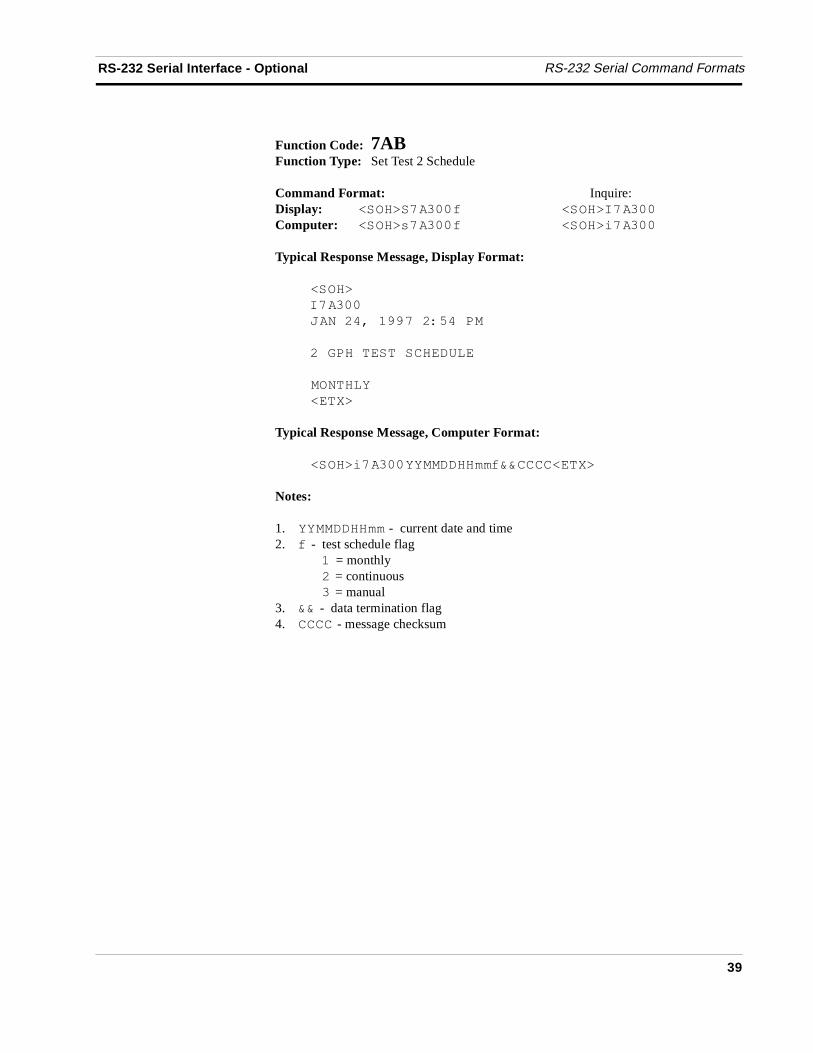
Function Code: 7ABFunction Type: Set Test 2 Schedule
Command Format: Inquire:Display: ����������; �����!����
Computer: ����������; �����(����
Typical Response Message, Display Format:
�����
!����
) � �������� �%���
�"����������������
� ����
�����
Typical Response Message, Computer Format:
�����(������������;�����������
Notes:
1. �������� - current date and time2. ; - test schedule flag
� = monthly = continuous� = manual
3. �� - data termination flag4. ���� - message checksum
RS-232 Serial Command Formats RS-232 Serial Interface - Optional
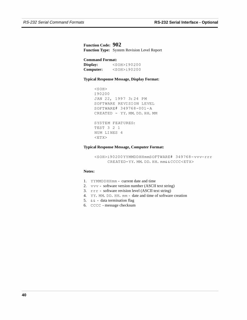
40
Function Code: 902Function Type: System Revision Level Report
Command Format:Display: �����!�� ��
Computer: �����(�� ��
Typical Response Message, Display Format:
�����
!�� ��
) � ��������� ���
��,�2�����+!�!� ���+��
��,�2��<�����&�4���4
�������4���$$��$��$
������,�������
�� ������� ��
�� ���! ����
�����
Typical Response Message, Computer Format:
�����(�� ������������,�2��<�����&�4===4888
�������4��$$��$��$�������������
Notes:
1. �������� - current date and time2. === - software version number (ASCII text string)3. 888 - software revision level (ASCII text string)4. ��$$��$��$�� - date and time of software creation5. �� - data termination flag6. ���� - message checksum
RS-232 Serial Interface - Optional RS-232 Serial Command Formats
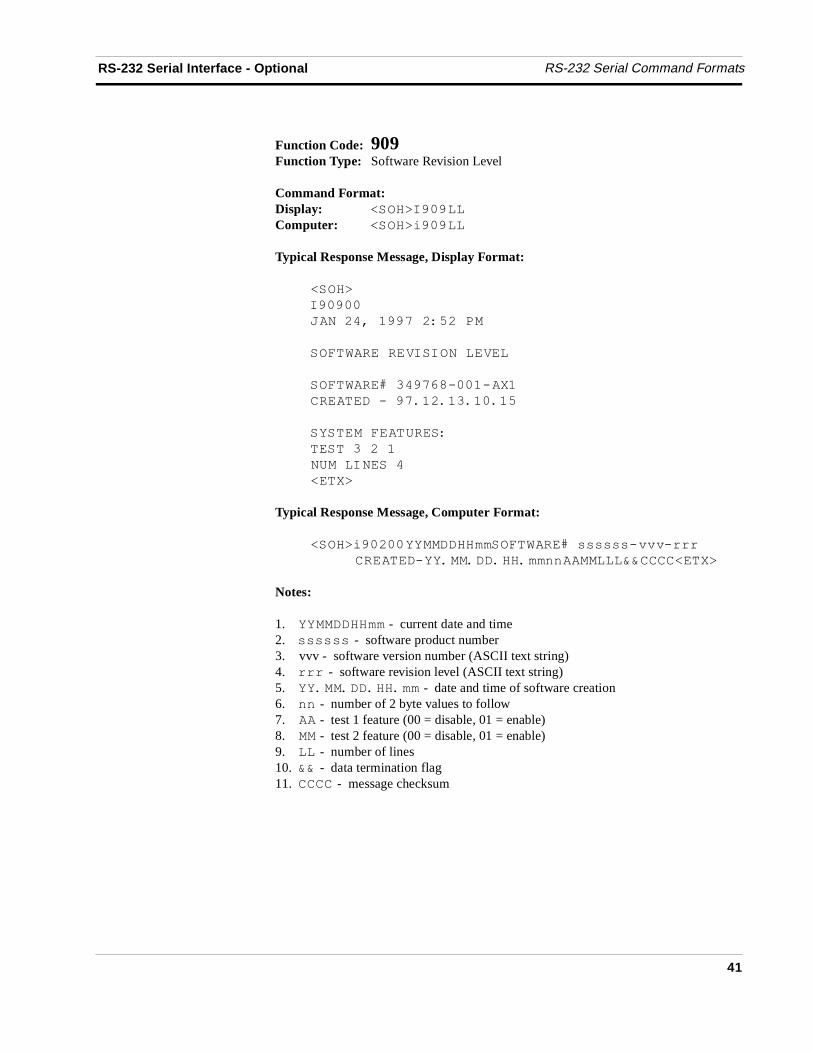
41
Function Code: 909Function Type: Software Revision Level
Command Format:Display: �����!�����
Computer: �����(�����
Typical Response Message, Display Format:
�����
!�����
) � �������� �% ��
��,�2�����+!�!� ���+��
��,�2��<�����&�4���4��
�������4���$� $��$��$�%
������,�������
�� ������� ��
�� ���! ����
�����
Typical Response Message, Computer Format:
�����(�� ������������,�2��<�������4===4888
������4��$$��$��$��..��������������
Notes:
1. �������� - current date and time2. ������ - software product number3. vvv - software version number (ASCII text string)4. 888 - software revision level (ASCII text string)5. ��$$��$��$�� - date and time of software creation6. .. - number of 2 byte values to follow7. - test 1 feature (00 = disable, 01 = enable)8. - test 2 feature (00 = disable, 01 = enable)9. �� - number of lines10. �� - data termination flag11. ���� - message checksum
RS-232 Serial Command Formats RS-232 Serial Interface - Optional
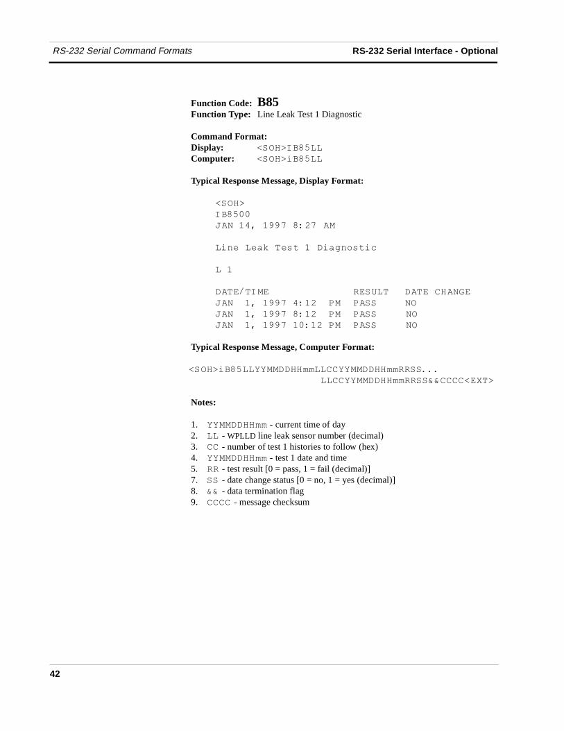
42
Function Code: B85Function Type: Line Leak Test 1 Diagnostic
Command Format:Display: �����!'�%��
Computer: �����('�%��
Typical Response Message, Display Format:
�����
!'�%��
) ������������ ��
�(./��/01��/�#����(0>.?�#(@
���
���*�!�� ������� ������ "�
) ������������� � � ��� �
) ������������� � � ��� �
) �������������� � ��� �
Typical Response Message, Computer Format:
�����('�%��������������������������$$$
���������������������������
Notes:
1. �������� - current time of day2. �� - WPLLD line leak sensor number (decimal)3. �� - number of test 1 histories to follow (hex)4. �������� - test 1 date and time5. �� - test result [0 = pass, 1 = fail (decimal)]7. �� - date change status [0 = no, 1 = yes (decimal)]8. �� - data termination flag9. ���� - message checksum
RS-232 Serial Interface - Optional RS-232 Serial Command Formats
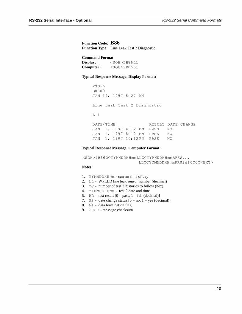
43
Function Code: B86Function Type: Line Leak Test 2 Diagnostic
Command Format:Display: �����!'�&��
Computer: �����('�&��
Typical Response Message, Display Format:
�����
'�&��
) ������������ ��
�(./��/01��/�#� ��(0>.?�#(@
���
���*�!� � ������������� "�
) ������������� � ��� �
) ������������� � ��� �
) �������������� � ��� �
Typical Response Message, Computer Format:
�����('�&--������������������������$$$
���������������������������
Notes:
1. �������� - current time of day2. �� - WPLLD line leak sensor number (decimal)3. �� - number of test 2 histories to follow (hex)4. �������� - test 2 date and time5. �� - test result [0 = pass, 1 = fail (decimal)]7. �� - date change status [0 = no, 1 = yes (decimal)]8. �� - data termination flag9. ���� - message checksum

RS-232 Serial Command Formats RS-232 Serial Interface - Optional
44
Glossary-1
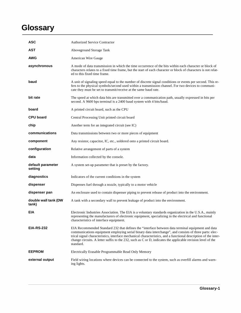
ASC Authorized Service Contractor
AST Aboveground Storage Tank
AWG American Wire Gauge
asynchronous A mode of data transmission in which the time occurrence of the bits within each character or block of characters relates to a fixed time frame, but the start of each character or block of characters is not relat-ed to this fixed time frame.
baud A unit of signaling speed equal to the number of discrete signal conditions or events per second. This re-fers to the physical symbols/second used within a transmission channel. For two devices to communi-cate they must be set to transmit/receive at the same baud rate.
bit rate The speed at which data bits are transmitted over a communication path, usually expressed in bits per second. A 9600 bps terminal is a 2400 baud system with 4 bits/baud.
board A printed circuit board, such as the CPU
CPU board Central Processing Unit printed circuit board
chip Another term for an integrated circuit (see IC)
communications Data transmissions between two or more pieces of equipment
component Any resistor, capacitor, IC, etc., soldered onto a printed circuit board.
configuration Relative arrangement of parts of a system
data Information collected by the console.
default parameter setting
A system set-up parameter that is preset by the factory.
diagnostics Indicators of the current conditions in the system
dispenser Dispenses fuel through a nozzle, typically to a motor vehicle
dispenser pan An enclosure used to contain dispenser piping to prevent release of product into the environment.
double wall tank (DW tank)
A tank with a secondary wall to prevent leakage of product into the environment.
EIA Electronic Industries Association. The EIA is a voluntary standards organization in the U.S.A., mainly representing the manufacturers of electronic equipment, specializing in the electrical and functional characteristics of interface equipment.
EIA-RS-232 EIA Recommended Standard 232 that defines the “interface between data terminal equipment and data communications equipment employing serial binary data interchange”, and consists of three parts: elec-trical signal characteristics, interface mechanical characteristics, and a functional description of the inter-change circuits. A letter suffix to the 232, such as C or D, indicates the applicable revision level of the standard.
EEPROM Electrically Erasable Programmable Read Only Memory
external output Field wiring locations where devices can be connected to the system, such as overfill alarms and warn-ing lights.
Glossary
Glossary
Glossary-2
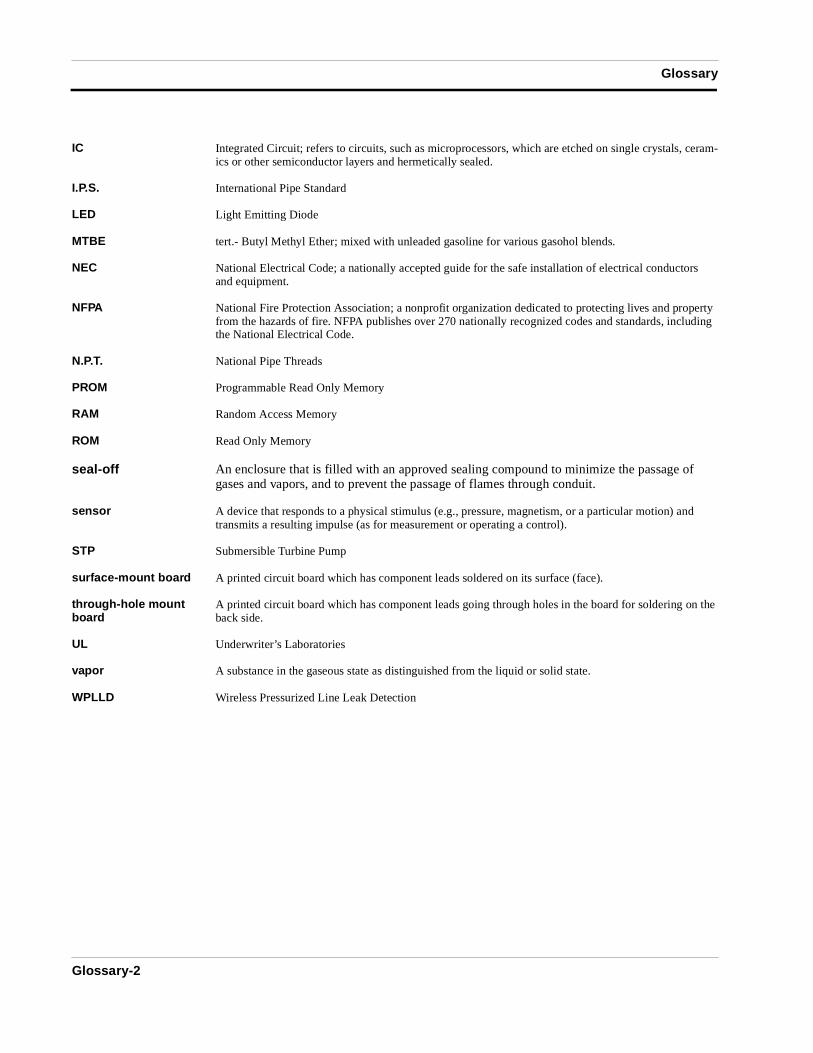
IC Integrated Circuit; refers to circuits, such as microprocessors, which are etched on single crystals, ceram-ics or other semiconductor layers and hermetically sealed.
I.P.S. International Pipe Standard
LED Light Emitting Diode
MTBE tert.- Butyl Methyl Ether; mixed with unleaded gasoline for various gasohol blends.
NEC National Electrical Code; a nationally accepted guide for the safe installation of electrical conductors and equipment.
NFPA National Fire Protection Association; a nonprofit organization dedicated to protecting lives and property from the hazards of fire. NFPA publishes over 270 nationally recognized codes and standards, including the National Electrical Code.
N.P.T. National Pipe Threads
PROM Programmable Read Only Memory
RAM Random Access Memory
ROM Read Only Memory
seal-off An enclosure that is filled with an approved sealing compound to minimize the passage of gases and vapors, and to prevent the passage of flames through conduit.
sensor A device that responds to a physical stimulus (e.g., pressure, magnetism, or a particular motion) and transmits a resulting impulse (as for measurement or operating a control).
STP Submersible Turbine Pump
surface-mount board A printed circuit board which has component leads soldered on its surface (face).
through-hole mount board
A printed circuit board which has component leads going through holes in the board for soldering on the back side.
UL Underwriter’s Laboratories
vapor A substance in the gaseous state as distinguished from the liquid or solid state.
WPLLD Wireless Pressurized Line Leak Detection

Sales OfficesVeeder-Root has offices around the world to serve you.
HeadquartersVeeder-Root Company125 Powder Forest DriveSimsbury, CT 06070-7684 U.S.A.(860) 651-2700 FAX: (860) 651-2719
EnglandVeeder-Root Environmental Systems LimitedHydrex House, Garden RoadRichmond, Surrey TW9 4NR ENGLAND44-181-392-1355
BrazilVeeder-Root do BRASILRua ado Benatti, 92Caixa Postal 834301051 Sao Paulo BRAZIL55-11-861-2155
GermanyVeeder-Root GmbHUhlandstrasse 49D-78554 Aldingen GERMANY49 (0)7424 1400
FranceVeeder-Root SARLZI des Mardelles94-106 rue Blaise Pascal93600 Aulnay-sous-Bois FRANCE33 (0)1 4879 5599
CanadaVeeder-Root Canada151 Superior Boulevard, Suite 24Mississauga, Ontario, L5T 2L1 CANADA905-670-2755
SingaporeVeeder-Root Singapore246 MacPherson Road#08-01 Betime Building348578 Singapore65 745 9265
MexicoVeeder-Root MexicoPrado de las CameliasNo. 4483-4Praddos Tepeyac C.P. 45500Zapopan, Jal., MEXICO(52) 36-47-3750
577013-602 rev: DEnvironmental Products
VEEDER-ROOT