Embed Size (px)
Citation preview
MDE-3243F
Meter Check Valve Retrofit Kits, Advantage® (K94254-01), Eclipse® (K94254-02), Encore® (K96623-01), and Encore
Flex Fuels (K96623-02) Installation Instructions January 2018
Introduction
PurposeThis manual provides instructions for installing the Meter Check Valve Retrofit Kits on existing Encore®, Atlas®, Legacy®, Eclipse®, and The Advantage® Series manifolds.
• The Advantage (K94254-01)• Eclipse (K94254-02)• Encore (K96623-01)• Encore Flex Fuels (K96623-02)
Note: Effective April 2016, to install meter check valve on Encore Ecometer™ units, use the Ecometer Check Valve Replacement Kit (K96623-03) and refer to MDE-5198 Encore, Ecometer Check Valve Kit (K96623-03) Installation Instructions.
Meter Check Valve Kits - Comprehensive Listing
Part Number Description ProductsReference Document
K94254-01 Meter Check Valve Retrofit Kit, The Advantage The Advantage MDE-3243
K94254-02 Meter Check Valve Kit, Eclipse Eclipse MDE-3243
K96623-01 Meter Check Valve Kit, Encore Encore Standard and Atlas
MDE-3243
K96623-02 Meter Check Valve Kit, Encore, Flex Fuels Encore Flex Fuels MDE-3243
K96623-03 Meter Check Valve Kit, Encore Ecometer Encore Ecometer MDE-5198
Note: The above table represents all the check valve kits for positive displacement meter applications (all C and V style meters).
Table of Contents
Topic Page
Introduction 1
Important Safety Information 4
Before You Begin 6
Removing Existing Meter 7
Installing Meter Check Valve Retrofit Kit 8
MDE-3243F Meter Check Valve Retrofit Kits, Advantage® (K94254-01), Eclipse® (K94254-02), Encore® (K96623-01), and Encore Flex Fuels (K96623-02) Installation Instructions · January 2018 Page 1
Introduction
Required Tools and MaterialsThe following tools and materials are required for installing the Meter Check Valve Retrofit Kit:
• Hexagonal Nut Driver Set• Pliers• Phillips® and Flat-blade Screwdrivers• Socket Wrenches• Silicone Grease• Fuel Collector Cup (K35493)• Torque Wrench• Absorbent Towels
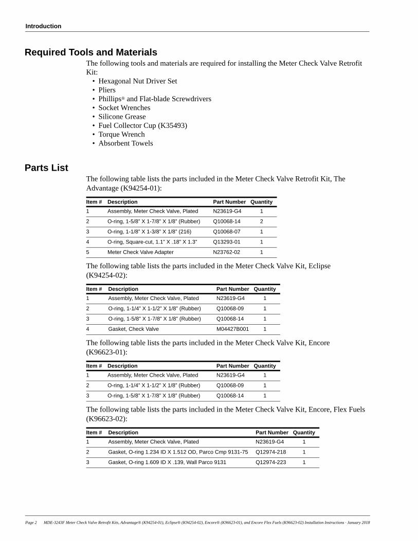
Parts ListThe following table lists the parts included in the Meter Check Valve Retrofit Kit, The Advantage (K94254-01):
Item # Description Part Number Quantity
1 Assembly, Meter Check Valve, Plated N23619-G4 1
2 O-ring, 1-5/8” X 1-7/8” X 1/8” (Rubber) Q10068-14 2
3 O-ring, 1-1/8” X 1-3/8” X 1/8” (216) Q10068-07 1
4 O-ring, Square-cut, 1.1” X .18” X 1.3” Q13293-01 1
5 Meter Check Valve Adapter N23762-02 1
The following table lists the parts included in the Meter Check Valve Kit, Eclipse (K94254-02):
Item # Description Part Number Quantity
1 Assembly, Meter Check Valve, Plated N23619-G4 1
2 O-ring, 1-1/4” X 1-1/2” X 1/8” (Rubber) Q10068-09 1
3 O-ring, 1-5/8” X 1-7/8” X 1/8” (Rubber) Q10068-14 1
4 Gasket, Check Valve M04427B001 1
The following table lists the parts included in the Meter Check Valve Kit, Encore (K96623-01):
Item # Description Part Number Quantity
1 Assembly, Meter Check Valve, Plated N23619-G4 1
2 O-ring, 1-1/4” X 1-1/2” X 1/8” (Rubber) Q10068-09 1
3 O-ring, 1-5/8” X 1-7/8” X 1/8” (Rubber) Q10068-14 1
The following table lists the parts included in the Meter Check Valve Kit, Encore, Flex Fuels (K96623-02):
Item # Description Part Number Quantity
1 Assembly, Meter Check Valve, Plated N23619-G4 1
2 Gasket, O-ring 1.234 ID X 1.512 OD, Parco Cmp 9131-75 Q12974-218 1
3 Gasket, O-ring 1.609 ID X .139, Wall Parco 9131 Q12974-223 1
Page 2 MDE-3243F Meter Check Valve Retrofit Kits, Advantage® (K94254-01), Eclipse® (K94254-02), Encore® (K96623-01), and Encore Flex Fuels (K96623-02) Installation Instructions · January 2018
Introduction
Required ReadingBefore installing this kit, the installer must read, understand, and follow:
• This manual• National Fire Protection Association (NFPA) 30A, The Automotive and Marine Service
Station Code• NFPA 70®, The National Electrical Code (NEC®)• Applicable federal, state, and local codes and regulations
Failure to do so may adversely affect the safe use and operation of the equipment.
Note: These kits must be installed by a Gilbarco® Authorized Service Contractor (ASC) to ensure warranty.
Related Documents
Document Number Title GOLDSM Library
MDE-2531 Gilbarco Pump and Dispenser Start-up and Service Manual
• Pump & Dispenser Start-up & Service Manual • Service Manual
MDE-2833 Pump and Dispenser Site Preparation Manual Site Prep
MDE-3802 Encore and Eclipse Site Preparation Manual • Site Prep• Encore and Eclipse• Encore and Eclipse Installers• Footprint and Elevation Library
MDE-3804 Encore and Eclipse Start-up/Service Manual • Encore and Eclipse• Service Manual
MDE-5198 Encore, Ecometer Check Valve Kit (K94254-02) Installation Instructions
• Encore and Eclipse• Kit Selection
Abbreviations and Acronyms
Term Description
ASC Authorized Service Contractor
GOLD Gilbarco Online Documentation
NEC National Electrical Code
NFPA National Fire Protection Association
OSHA Occupational Safety and Health Administration
STP Submersible Turbine Pump
MDE-3243F Meter Check Valve Retrofit Kits, Advantage® (K94254-01), Eclipse® (K94254-02), Encore® (K96623-01), and Encore Flex Fuels (K96623-02) Installation Instructions · January 2018 Page 3
Page 4 MDE-3243F Meter Check Valve Retrofit Kits, Advantage® (K94254-01), Eclipse® (K94254-02), Encore® (K96623-01), and Encore Flex Fuels (K96623-02) Installation Instructions · January 2018
Important Safety Information
Important Safety InformationNotes: 1) Save this Important Safety Information section in a
readily accessible location.
2) Although DEF is non-flammable, Diesel is flammable. Therefore, for DEF cabinets that are attached to Diesel dispensers, follow all the notes in this section that pertain to flammable fuels.
This section introduces the hazards and safety precautions associated with installing, inspecting, maintaining, or servicing this product. Before performing any task on this product, read this safety information and the applicable sections in this manual, where additional hazards and safety precautions for your task will be found. Fire, explosion, electrical shock, or pressure release could occur and cause death or serious injury, if these safe service procedures are not followed.
Preliminary PrecautionsYou are working in a potentially dangerous environment of flammable fuels, vapors, and high voltage or pressures. Only trained or authorized individuals knowledgeable in the related procedures should install, inspect, maintain, or service this equipment.
Emergency Total Electrical Shut-OffThe first and most important information you must know is how to stop all fuel flow to the pump/dispenser and island. Locate the switch or circuit breakers that shut off all power to all fueling equipment, dispensing devices, and Submerged Turbine Pumps (STPs).
Total Electrical Shut-Off Before AccessAny procedure that requires access to electrical components or the electronics of the dispenser requires total electrical shut off of that unit. Understand the function and location of this switch or circuit breaker before inspecting, installing, maintaining, or servicing Gilbarco equipment.
Evacuating, Barricading, and Shutting OffAny procedure that requires access to the pump/dispenser or STPs requires the following actions:
• An evacuation of all unauthorized persons and vehicles from the work area
• Use of safety tape, cones, or barricades at the affected unit(s)
• A total electrical shut-off of the affected unit(s)Read the ManualRead, understand, and follow this manual and any other labels or related materials supplied with this equipment. If you do not understand a procedure, call the Gilbarco Technical Assistance Center (TAC) at 1-800-743-7501. It is imperative to your safety and the safety of others to understand the procedures before beginning work.
Follow the RegulationsApplicable information is available in National Fire Protection Association (NFPA) 30A; Code for Motor Fuel Dispensing Facilities and Repair Garages, NFPA 70; National Electrical Code (NEC), Occupational Safety and Health Administration (OSHA) regulations and federal, state, and local codes. All these regulations must be followed. Failure to install, inspect, maintain, or service this equipment in accordance with these codes, regulations, and standards may lead to legal citations with penalties or affect the safe use and operation of the equipment.Replacement PartsUse only genuine Gilbarco replacement parts and retrofit kits on your pump/dispenser. Using parts other than genuine Gilbarco replacement parts could create a safety hazard and violate local regulations.Federal Communications Commission (FCC) WarningThis equipment has been tested and found to comply with thelimits for a Class A digital device pursuant to Part 15 of the FCC Rules. These limits are designed to provide reasonable protection against harmful interference when the equipment is operated in a commercial environment. This equipment generates, uses, and can radiate radio frequency energy, and if not installed and used in accordance with the instruction manual, may cause harmful interference to radio communications. Operation of this equipment in a residential area is likely to cause harmful interference in which case the user will be required to correct the interference at his own expense. Changes or modifications not expressly approved by the manufacturer could void the user’s authority to operate this equipment.
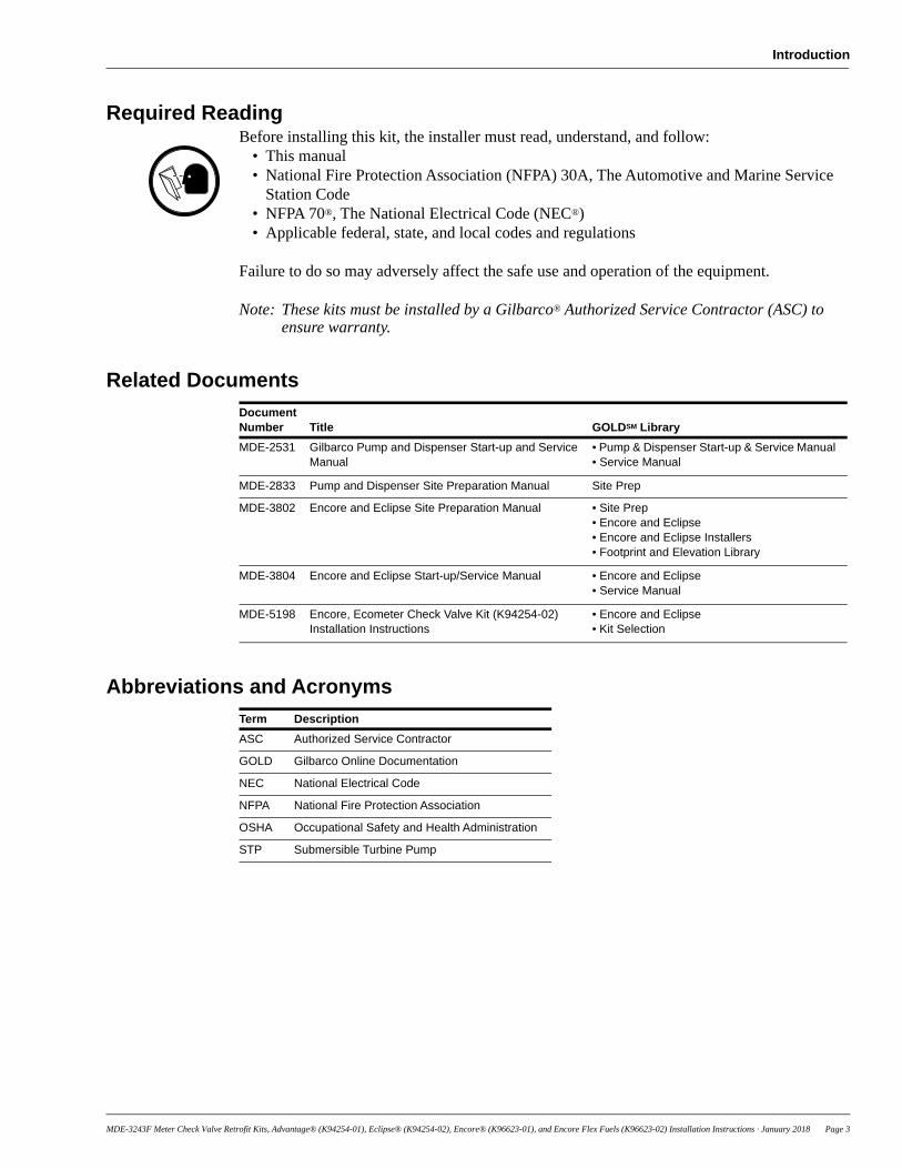
Safety Symbols and Warning WordsThis section provides important information about warning symbols and boxes.Alert Symbol
This safety alert symbol is used in this manual and on warning labels to alert you to a precaution which must be followed to prevent potential personal safety hazards. Obey safety directives that follow this symbol to avoid possible injury or death.Signal WordsThese signal words used in this manual and on warning labels tell you the seriousness of particular safety hazards. The precautions below must be followed to prevent death, injury, or damage to the equipment:
DANGER: Alerts you to a hazard or unsafe practice which will result in death or serious injury.WARNING: Alerts you to a hazard or unsafe practice that could result in death or serious injury. CAUTION with Alert symbol: Designates a hazard or unsafe practice which may result in minor injury.CAUTION without Alert symbol: Designates a hazard or unsafe practice which may result in property or equipment damage.
Working With Fuels and Electrical EnergyPrevent Explosions and FiresFuels and their vapors will explode or burn, if ignited. Spilled or leaking fuels cause vapors. Even filling customer tanks will cause potentially dangerous vapors in the vicinity of the dispenser or island.
DEF is non-flammable. Therefore, explosion and fire safety warnings do not apply to DEF lines.
The EMERGENCY STOP, ALL STOP, and PUMP STOP buttons at the cashier’s station WILL NOT shut off electrical power to the pump/dispenser. This means that even if you activate these stops, fuel may continue to flow uncontrolled. You must use the TOTAL ELECTRICAL SHUT-OFF in the case of an emergency and not the console’s ALL STOP and PUMP STOP or similar keys.
! WARNING!
!
!
!

MDE-3243F Meter Check Valve Retrofit Kits, Advantage® (K94254-01), Eclipse® (K94254-02), Encore® (K96623-01), and Encore Flex Fuels (K96623-02) Installation Instructions · January 2018 Page 5
Important Safety Information
No Open Fire
Open flames from matches, lighters, welding torches, or other sources can ignite fuels and their vapors.No Sparks - No Smoking
Sparks from starting vehicles, starting, or using power tools, burning cigarettes, cigars, or pipes can also ignite fuels and their vapors. Static electricity, including an electrostatic charge on your body, can cause a spark sufficient to ignite fuel vapors. Every time you get out of a vehicle, touch the metal of your vehicle, to discharge any electrostatic charge before you approach the dispenser island.
Working AloneIt is highly recommended that someone who is capable of rendering first aid be present during servicing. Familiarize yourself with Cardiopulmonary Resuscitation (CPR) methods, if you work with or around high voltages. This information is available from the American Red Cross. Always advise the station personnel about where you will be working, and caution them not to activate power while you are working on the equipment. Use the OSHA Lockout/Tagout procedures. If you are not familiar with this requirement, refer to this information in the service manual and OSHA documentation.
Working With Electricity SafelyEnsure that you use safe and established practices in working with electrical devices. Poorly wired devices may cause a fire, explosion, or electrical shock. Ensure that grounding connections are properly made. Take care that sealing devices and compounds are in place. Ensure that you do not pinch wires when replacing covers. Follow OSHA Lockout/Tagout requirements. Station employees and service contractors need to understand and comply with this program completely to ensure safety while the equipment is down.
Hazardous MaterialsSome materials present inside electronic enclosures may present a health hazard if not handled correctly. Ensure that you clean hands after handling equipment. Do not place any equipment in the mouth.
In an EmergencyInform Emergency PersonnelCompile the following information and inform emergency personnel:
• Location of accident (for example, address, front/back of building, and so on)
• Nature of accident (for example, possible heart attack, run over by car, burns, and so on)
• Age of victim (for example, baby, teenager, middle-age, elderly)
• Whether or not victim has received first aid (for example, stopped bleeding by pressure, and so on)
• Whether or not a victim has vomited (for example, if swallowed or inhaled something, and so on)
IMPORTANT: Oxygen may be needed at scene if gasoline has been ingested or inhaled. Seek medical advice immediately.
Lockout/TagoutLockout/Tagout covers servicing and maintenance of machines and equipment in which the unexpected energization or start-up of the machine(s) or equipment or release of stored energy could cause injury to employees or personnel. Lockout/Tagout applies to all mechanical, hydraulic, chemical, or other energy, but does not cover electrical hazards. Subpart S of 29 CFR Part 1910 - Electrical Hazards, 29 CFR Part 1910.333 contains specific Lockout/Tagout provision for electrical hazards.
The pump/dispenser contains a chemical known to the State of California to cause cancer.
WARNING!
The pump/dispenser contains a chemical known to the State of California to cause birth defects or other reproductive harm.
WARNING!
Gasoline/DEF ingested may cause unconsciousness and burns to internal organs. Do not induce vomiting. Keep airway open. Oxygen may be needed at scene. Seek medical advice immediately.
!
DEF generates ammonia gas at higher temperatures. When opening enclosed panels, allow the unit to air out to avoid breathing vapors. If respiratory difficulties develop, move victim away from source of exposure and into fresh air. If symptoms persist, seek medical attention.
WARNING!
WARNING
Gasoline inhaled may cause unconsciousness and burns to lips, mouth, and lungs. Keep airway open. Seek medical advice immediately.
WARNING!
Gasoline/DEF spilled in eyes may cause burns to eye tissue. Irrigate eyes with water for approximately 15 minutes. Seek medical advice immediately.
WARNING!
Gasoline/DEF spilled on skin may cause burns.Wash area thoroughly with clear water.Seek medical advice immediately.
WARNING!
DEF is mildly corrosive. Avoid contact with eyes, skin, and clothing. Ensure that eyewash stations and safety showers are close to the work location. Seek medical advice/recommended treatment if DEF spills into eyes.
WARNING!

Before You Begin
Before You BeginRead and understand all safety information found in MDE-2531 Gilbarco Pump and Dispenser Start-up and Service Manual or MDE-3804 Encore and Eclipse Start-up/Service Manual.
A clean work area is a requirement for this procedure. It is imperative that no contamination be allowed to enter the meter assembly. Use absorbent towels to clean surface during this procedure.
Meter lockup due to the introduction of contaminants is not covered under warranty.
CAUTION
To prepare the site and dispenser for the installation, proceed as follows:
1 Inform the manager.
2 Barricade the unit to be worked on.
3 Remove power to the unit at the breaker panel and all associated STPs and blenders. Follow OSHA lockout/tagout procedures.
4 Match the parts received in the kit with “Parts List” on page 2.
Failure to turn off the unit during kit installation may cause injury or bodily harm from electrical shock. Ensure that all power to the unit is switched off before opening the door to the unit and during kit installation.
WARNING
Two-stage Valve TestTesting two-stage valves is necessary to ensure that the valves remain closed (not leaking) when not engaged.
To test the valves for leaks, proceed as follows:Note: To determine if a valve leaks, the line must be pressurized, the valve must be
deactivated, and the nozzle must be opened. If the meter turns, the valve is leaking and must be replaced or rebuilt before proceeding.
1 Place the nozzle into approved container before activating.
2 Apply line pressure while the valve is deactivated. This can be done in two ways:• The coil of the valve being tested can be removed or disconnected and then the nozzle
handle associated with that valve can be engaged. This will turn on the STP and apply line pressure (This would normally open the valve, which is why it has been disconnected.).
• The STP of the grade being tested can be activated by engaging the nozzle handle on the opposite side of the pump from the valve being tested. Then the nozzle can be opened and the meter checked to determine if any leakage is occurring. For example, to test mid-grade side A valve, turn on mid-grade side B (flip side B nozzle handle), open mid-grade side A nozzle, and observe mid-grade side A meter.
Page 6 MDE-3243F Meter Check Valve Retrofit Kits, Advantage® (K94254-01), Eclipse® (K94254-02), Encore® (K96623-01), and Encore Flex Fuels (K96623-02) Installation Instructions · January 2018

Removing Existing Meter
3 Observe the meter for one minute. If the meter rotates, replace or rebuild the Two-stage Valve (R19093-02) using the Solenoid Repair Kit.
4 After all valves have been tested, proceed to “Removing Existing Meter”.
Removing Existing MeterTo remove the existing meter, proceed as follows:
IMPORTANT INFORMATIONOn The Advantage Series, the meter located on the far right of either side is easier toreach if the opposite meter is removed first.
Note: Read and follow all safety precautions in “Important Safety Information” on page 4.
1 Remove the lower hydraulics door.Note: Removing the side sheathing may make it easier to access the meter. Remove the side
sheathing if necessary.
2 Close and test all shear valves on dispensers to check that they seal mechanically.
3 Press CLEAR then ENTER on the manager keypad.
4 Open the nozzle into approved container to bleed pressure. Some residual pressure may remain.
5 Remove the pulser from the meter drive shaft (Legacy electronic models only).
6 Support the meter when removing bolts.
7 Remove the meter discharge line flange and meter inlet line flange bolts.
8 Remove the meter bracket bolts.Note: It is not necessary to remove the bracket.
9 Remove the meter.
MDE-3243F Meter Check Valve Retrofit Kits, Advantage® (K94254-01), Eclipse® (K94254-02), Encore® (K96623-01), and Encore Flex Fuels (K96623-02) Installation Instructions · January 2018 Page 7
Installing Meter Check Valve Retrofit Kit
Installing Meter Check Valve Retrofit KitTo install the Meter Check Valve Retrofit Kit, proceed as follows:
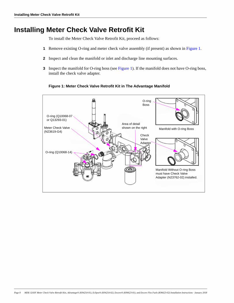
1 Remove existing O-ring and meter check valve assembly (if present) as shown in Figure 1.
2 Inspect and clean the manifold or inlet and discharge line mounting surfaces.
3 Inspect the manifold for O-ring boss (see Figure 1). If the manifold does not have O-ring boss, install the check valve adapter.
Figure 1: Meter Check Valve Retrofit Kit in The Advantage Manifold
Meter Check Valve(N23619-G4)
O-ring (Q10068-07 or Q13293-01)
O-ring (Q10068-14)
Area of detail shown on the right Manifold with O-ring Boss
Manifold Without O-ring Boss must have Check Valve Adapter (N23762-02) installed.
O-ringBoss
Check ValveAdapter
Page 8 MDE-3243F Meter Check Valve Retrofit Kits, Advantage® (K94254-01), Eclipse® (K94254-02), Encore® (K96623-01), and Encore Flex Fuels (K96623-02) Installation Instructions · January 2018
Installing Meter Check Valve Retrofit Kit
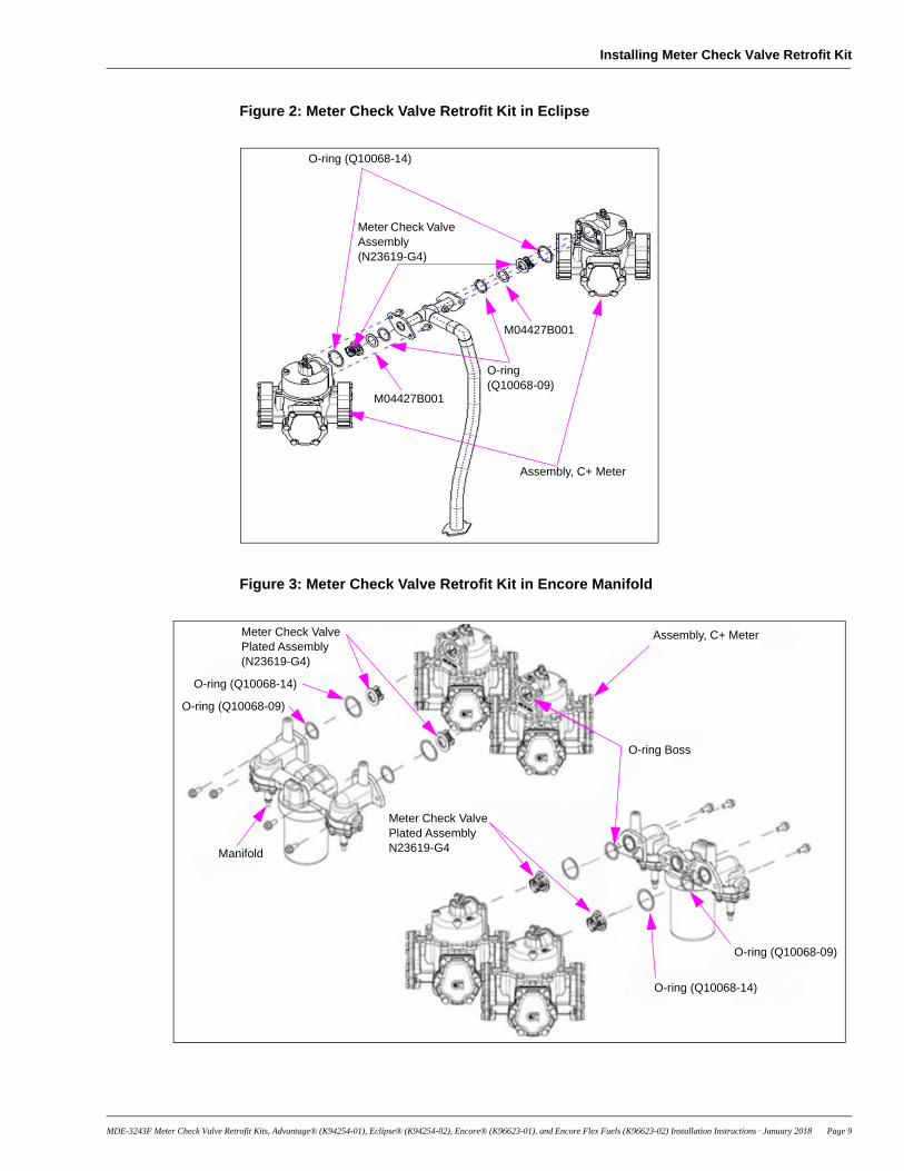
Figure 2: Meter Check Valve Retrofit Kit in Eclipse
O-ring (Q10068-14)
Assembly, C+ Meter
Meter Check Valve Assembly (N23619-G4)
M04427B001
O-ring (Q10068-09)
M04427B001
Figure 3: Meter Check Valve Retrofit Kit in Encore Manifold
Meter Check Valve Plated Assembly (N23619-G4)
O-ring (Q10068-14)
O-ring (Q10068-09)
Manifold
Assembly, C+ Meter
Meter Check Valve Plated Assembly N23619-G4
O-ring (Q10068-14)
O-ring (Q10068-09)
O-ring Boss
MDE-3243F Meter Check Valve Retrofit Kits, Advantage® (K94254-01), Eclipse® (K94254-02), Encore® (K96623-01), and Encore Flex Fuels (K96623-02) Installation Instructions · January 2018 Page 9
Installing Meter Check Valve Retrofit Kit
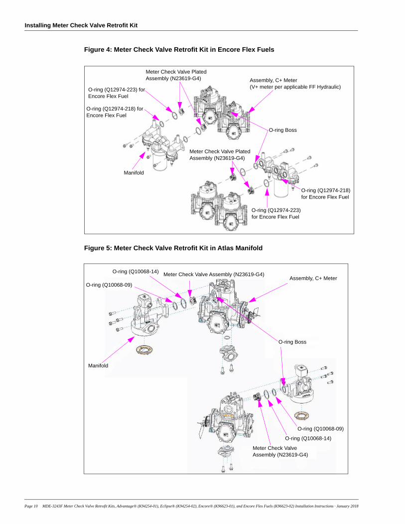
Figure 4: Meter Check Valve Retrofit Kit in Encore Flex Fuels
O-ring (Q12974-223) for Encore Flex Fuel
Meter Check Valve Plated Assembly (N23619-G4)
O-ring (Q12974-218) for Encore Flex Fuel
Manifold
Assembly, C+ Meter(V+ meter per applicable FF Hydraulic)
Meter Check Valve Plated Assembly (N23619-G4)
O-ring (Q12974-223) for Encore Flex Fuel
O-ring Boss
O-ring (Q12974-218) for Encore Flex Fuel
Figure 5: Meter Check Valve Retrofit Kit in Atlas Manifold
Meter Check Valve Assembly (N23619-G4)O-ring (Q10068-14)
O-ring (Q10068-09)
Manifold
Assembly, C+ Meter
Meter Check Valve Assembly (N23619-G4)
O-ring (Q10068-14)
O-ring (Q10068-09)
O-ring Boss
Page 10 MDE-3243F Meter Check Valve Retrofit Kits, Advantage® (K94254-01), Eclipse® (K94254-02), Encore® (K96623-01), and Encore Flex Fuels (K96623-02) Installation Instructions · January 2018
Installing Meter Check Valve Retrofit Kit
4 Lubricate two larger O-rings (Q10068-14 or Q12974-223, in case of Flex Fuels) with silicone grease. Insert one O-ring (Q10068-14 or Q12974-223, in case of Flex Fuels) into the groove in meter cover on the inlet side. Insert the other O-ring (Q10068-14 or Q12974-223, in case of Flex Fuels) into the groove in meter cover on the discharge side.
5
Model Manufacture Date Use
Legacy Before March 22, 1995 Square-cut O-ring (Q13293-01)
Legacy On or after March 22, 1995 O-ring (Q10068-07)
The Advantage Series Before March 20, 1995 Square-cut O-ring (Q13293-01)
The Advantage Series On or after March 20, 1995 O-ring (Q10068-07)
Eclipse All models O-ring (Q10068-09)
Encore Standard Unit All models O-ring (Q10068-09)
Encore Flex Fuels All models O-ring (Q12974-218)
Lubricate and insert the smaller O-ring (Q10068-07, Q13293-01, Q10068-09, or Q12974-218) on the manifold. The following table provides information to determine which O-ring to use:
6 Insert the Meter Check Valve Assembly (N23619-G4) into the meter cover through O-ring. Rotate assembly until it fits all the way into groove. The check valve must fit inside the O-ring installed in step 3 on page 8.
Installing MeterTo install the new meter, proceed as follows:
1 Replace the meter.Note: On The Advantage Series, carefully guide ball/pin drive on top of the meter into the
universal pulser drive.
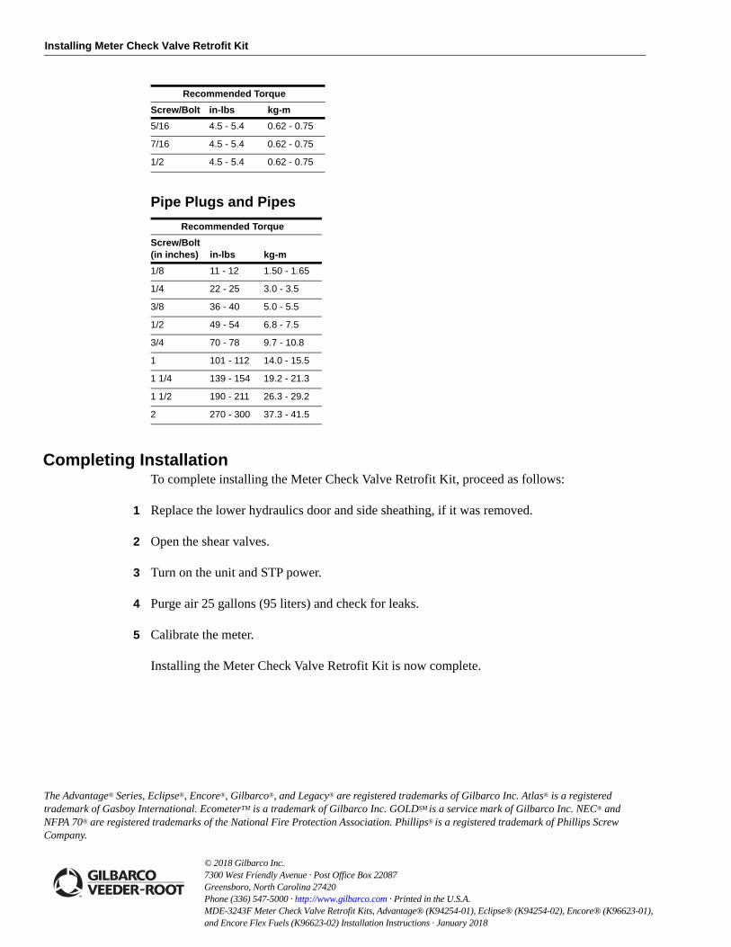
2 Bolt the meter to inlet and discharge flanges. Refer to “Screws and Bolts (Plated)” and “Pipe Plugs and Pipes” on page 12.
3 Bolt the meter to mounting brackets.
4 Replace the pulser and associated hardware as required.
The following tables provide torque specifications for screws and bolts, pipe plugs and pipes, flanged and compression tube fittings, self-contained pumping units, and meter bolts:
Screws and Bolts (Plated)
Recommended Torque
Screw/Bolt in-lbs kg-m
#2 2.0 - 2.3 0.02 - 0.03
#3 3.0 - 3.4 0.03 - 0.04
#4 4.5 - 5.4 0.05 - 0.06
#5 6.3 - 7.2 0.07 - 0.08
#6 9.0 - 10.0 0.10 - 0.14
#8 16.0 - 18.0 0.18 - 0.21
#10 26.0 - 29.0 0.30 - 0.33
1/4 4.5 - 5.4 0.62 - 0.75
MDE-3243F Meter Check Valve Retrofit Kits, Advantage® (K94254-01), Eclipse® (K94254-02), Encore® (K96623-01), and Encore Flex Fuels (K96623-02) Installation Instructions · January 2018 Page 11
Installing Meter Check Valve Retrofit Kit
Pipe Plugs and Pipes
Recommended Torque
Screw/Bolt (in inches) in-lbs kg-m
1/8 11 - 12 1.50 - 1.65
1/4 22 - 25 3.0 - 3.5
3/8 36 - 40 5.0 - 5.5
1/2 49 - 54 6.8 - 7.5
3/4 70 - 78 9.7 - 10.8
1 101 - 112 14.0 - 15.5
1 1/4 139 - 154 19.2 - 21.3
1 1/2 190 - 211 26.3 - 29.2
2 270 - 300 37.3 - 41.5
Completing InstallationTo complete installing the Meter Check Valve Retrofit Kit, proceed as follows:
1 Replace the lower hydraulics door and side sheathing, if it was removed.
2 Open the shear valves.
3 Turn on the unit and STP power.
4 Purge air 25 gallons (95 liters) and check for leaks.
5 Calibrate the meter.
Installing the Meter Check Valve Retrofit Kit is now complete.
5/16 4.5 - 5.4 0.62 - 0.75
7/16 4.5 - 5.4 0.62 - 0.75
1/2 4.5 - 5.4 0.62 - 0.75
Recommended Torque
Screw/Bolt in-lbs kg-m
© 2018 Gilbarco Inc. 7300 West Friendly Avenue · Post Office Box 22087Greensboro, North Carolina 27420 Phone (336) 547-5000 · http://www.gilbarco.com · Printed in the U.S.A.MDE-3243F Meter Check Valve Retrofit Kits, Advantage® (K94254-01), Eclipse® (K94254-02), Encore® (K96623-01), and Encore Flex Fuels (K96623-02) Installation Instructions · January 2018
The Advantage® Series, Eclipse®, Encore®, Gilbarco®, and Legacy® are registered trademarks of Gilbarco Inc. Atlas® is a registered trademark of Gasboy International. EcometerTM is a trademark of Gilbarco Inc. GOLDSM is a service mark of Gilbarco Inc. NEC® and NFPA 70® are registered trademarks of the National Fire Protection Association. Phillips® is a registered trademark of Phillips Screw Company.


![Untitled-1 [] · 2016-02-24 · Gilbarco Veeder-Root India Pvt Ltd. 1st Floor, Tower 1, Equinox Business Park, BKC, LBS Road, Mumbai- 400 070,lndia -rel: +9122 6637 9000 E-mail: frontier.ind@gilbarco.com](https://img.pdfslide.us/doc/110x75/5ed9bbc7130c491be656988d/untitled-1-2016-02-24-gilbarco-veeder-root-india-pvt-ltd-1st-floor-tower.jpg)