Embed Size (px)
Citation preview
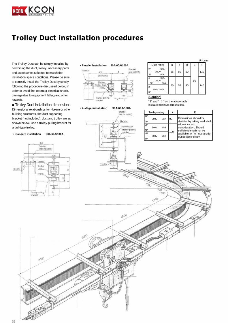
Trolley Duct installation procedures
The Trolley Duct can be simply installed by
combining the duct, trolley, necessary parts
and accessories selected to match the
installation space conditions. Please be sure
to correctly install the Trolley Duct by strictly
following the procedure discussed below, in
order to avoid fire, operator electrical shock,
damage due to equipment falling and other
hazards.
■ Trolley Duct installation dimensions Dimensional relationships for I-beam or other
building structures, the duct supporting
bracket (not included), duct and trolley are as
shown below. Use a trolley-pulling bracket for
a pull-type trolley.
• Standard installation 30A/60A/100A
Unit: mm
Duct rating a b d S ℓ
2P 30A 300V
3P 60A 65 50 60
50
110
4P 30A 300V
5P 60A 60A 60 55 90 140
2P 600V 100A
3P
(Caution) "S" and " ℓ " on the above table
indicate minimum dimensions.
Trolley rating c E
2P 300V 20A
3P 92 Dimensions should be
decided by taking lead slack allowance into consideration. Should sufficient length not be available for "e," use a side outlet cable trolley.
2P 300V 40A
3P 100
4P 300V 20A
5P
• Parallel installation 30A/60A/100A
• 2-stage installation 30A/60A/100A
2P 600V 40A
3P
2P 600V 80A
3P 120
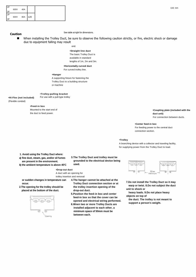
Caution
Unit: mm
1. Avoid using the Trolley Duct where: a) fine dust, steam, gas, and/or oil fumes
are present in the environment.
b) the ambient temperature is above 40'C
or sudden changes in temperature can
occur.
2.The opening for the trolley should be
placed at the bottom of the duct.
3.The Trolley Duct and trolley must be
grounded to the electrical device being
used.
4.The hanger cannot be attached at the
Trolley Duct connection section or at
the trolley insertion opening of the
drop-out duct. 5.Position the feed-in box and center
feed-in box so that the cover can be
opened and electrical wiring performed. 6.Wnen two or more Trolley Ducts are
installed adjacent to each other, a
minimum space of 50mm must be
between each.
7.Do not install the Trolley Duct so it may warp or twist. 8.Do not subject the duct
unit to shock or heavy loads. 9.Do not place heavy
objects on top of the duct. The trolley is not meant to support a person's weight.
•Coupling plate (included with the
duct unit) For connection between ducts.
•Center feed-in box For feeding power to the central duct
connection section.
•Trolley A branching device with a collector and traveling facility,
for supplying power from the Trolley Duct to load.
•Drop-out duct A duct with an opening for
trolley insertion and removal
•Feed-in box Mounted to the start end of
the duct to feed power.
•Hi-Flex (not included) (Flexible conduit)
•Hanger A supporting fixture for fastening the
Trolley Duct to a building structure
or machine
•Trolley-pulling bracket
For use with a pull-type trolley
•Horizontally curved duct For curved trolley line.
•End cap For closing the duct
end.
See table at right for dimensions.
•Straight line duct
The basic Trolley Duct is
available in standard
lengths of 1m, 2m and 3m.
When installing the Trolley Duct, be sure to observe the following caution strictly, or fire, electric shock or damage due to equipment falling may result
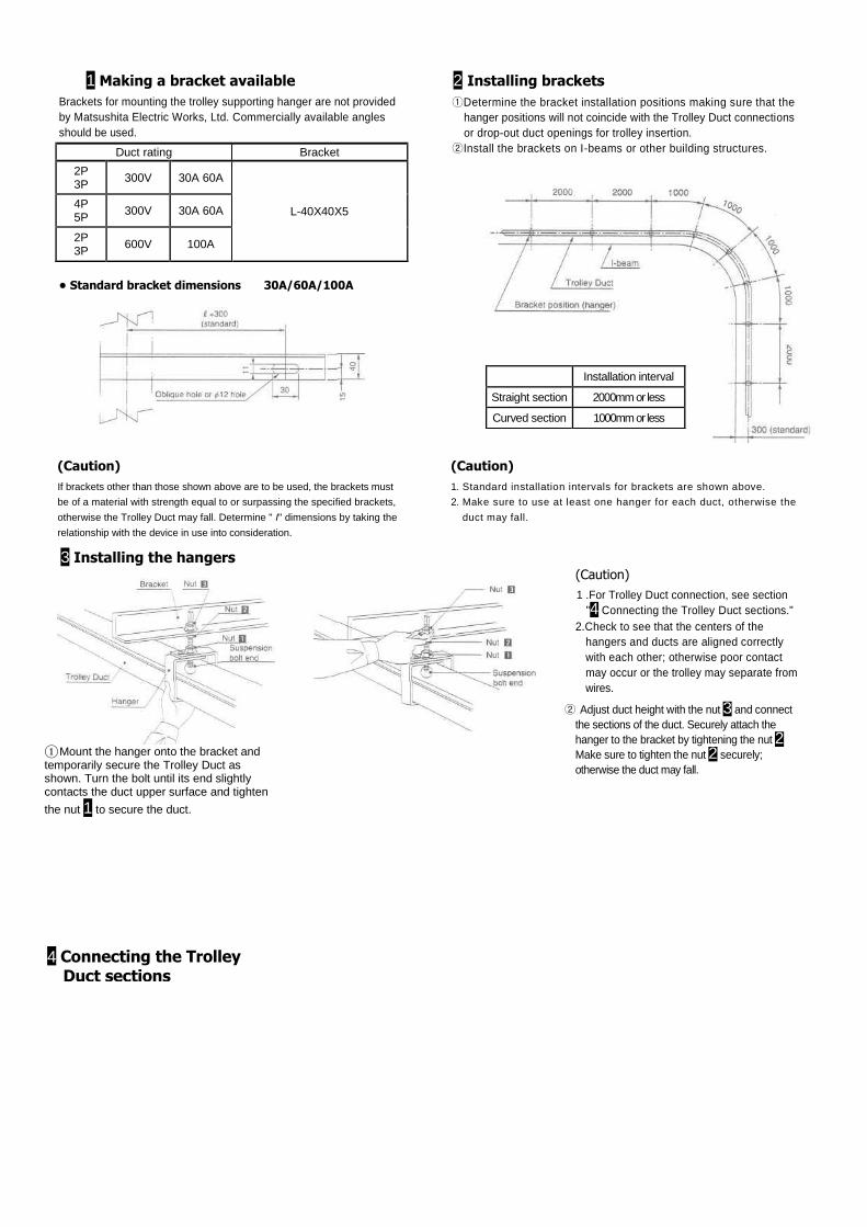
1 Making a bracket available
Brackets for mounting the trolley supporting hanger are not provided
by Matsushita Electric Works, Ltd. Commercially available angles
should be used.
Duct rating Bracket
2P 3P
300V 30A 60A
L-40X40X5 4P 5P
300V 30A 60A
2P 3P
600V 100A
• Standard bracket dimensions 30A/60A/100A
2 Installing brackets
①Determine the bracket installation positions making sure that the
hanger positions will not coincide with the Trolley Duct connections
or drop-out duct openings for trolley insertion.
②Install the brackets on I-beams or other building structures.
(Caution)
If brackets other than those shown above are to be used, the brackets must
be of a material with strength equal to or surpassing the specified brackets,
otherwise the Trolley Duct may fall. Determine " I" dimensions by taking the
relationship with the device in use into consideration.
(Caution)
1. Standard installation intervals for brackets are shown above.
2. Make sure to use at least one hanger for each duct, otherwise the
duct may fall.
3 Installing the hangers (Caution)
1 .For Trolley Duct connection, see section
"4 Connecting the Trolley Duct sections."
2.Check to see that the centers of the
hangers and ducts are aligned correctly
with each other; otherwise poor contact
may occur or the trolley may separate from
wires.
① Mount the hanger onto the bracket and temporarily secure the Trolley Duct as shown. Turn the bolt until its end slightly contacts the duct upper surface and tighten
the nut 1 to secure the duct.
② Adjust duct height with the nut 3 and connect
the sections of the duct. Securely attach the
hanger to the bracket by tightening the nut 2
Make sure to tighten the nut 2 securely;
otherwise the duct may fall.
Unit: mm
Installation interval
Straight section 2000mm or less
Curved section 1000mm or less
4 Connecting the Trolley Duct sections
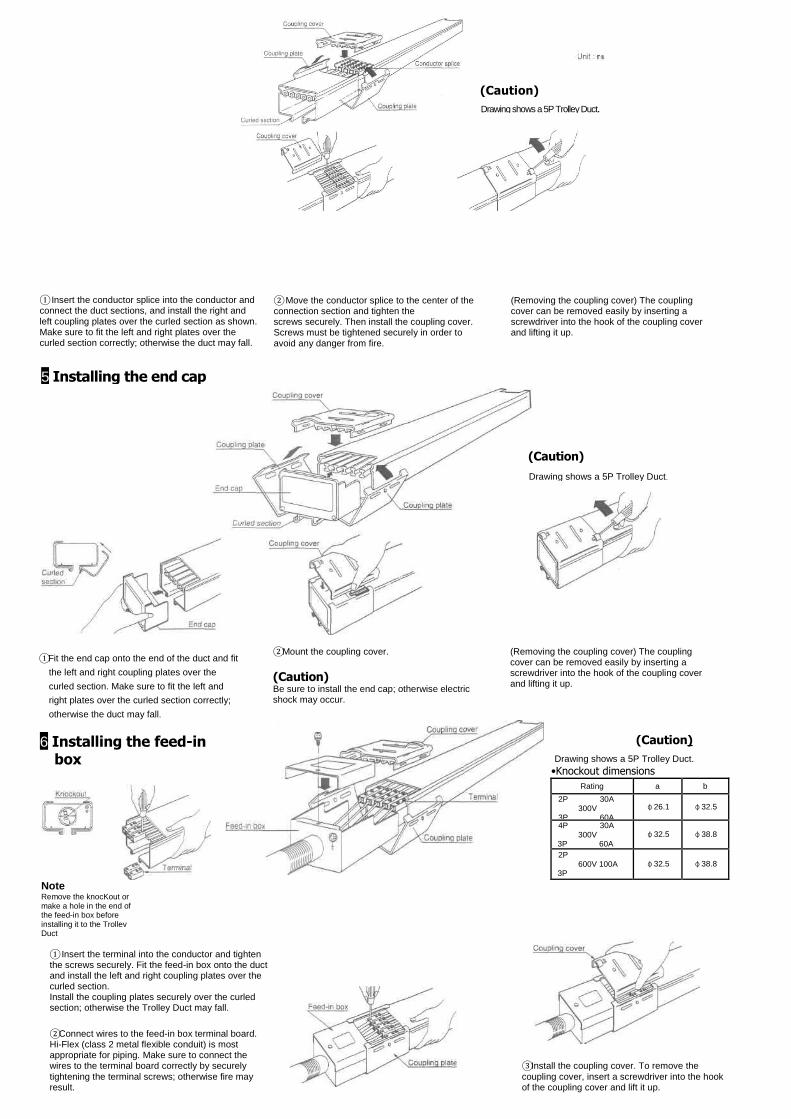
① Insert the conductor splice into the conductor and connect the duct sections, and install the right and left coupling plates over the curled section as shown. Make sure to fit the left and right plates over the curled section correctly; otherwise the duct may fall.
② Move the conductor splice to the center of the connection section and tighten the screws securely. Then install the coupling cover. Screws must be tightened securely in order to avoid any danger from fire.
(Removing the coupling cover) The coupling cover can be removed easily by inserting a screwdriver into the hook of the coupling cover and lifting it up.
①Fit the end cap onto the end of the duct and fit
the left and right coupling plates over the
curled section. Make sure to fit the left and
right plates over the curled section correctly;
otherwise the duct may fall.
②Mount the coupling cover.
(Caution) Be sure to install the end cap; otherwise electric shock may occur.
(Removing the coupling cover) The coupling cover can be removed easily by inserting a screwdriver into the hook of the coupling cover and lifting it up.
6 Installing the feed-in box
(Caution)
Drawing shows a 5P Trolley Duct. •Knockout dimensions
Rating a b
2P 30A 300V 3P 60A
φ26.1 φ32.5
4P 30A 300V 3P 60A
φ32.5 φ38.8
2P 600V 100A 3P
φ32.5 φ38.8
Note Remove the knocKout or make a hole in the end of the feed-in box before installing it to the Trollev Duct
① Insert the terminal into the conductor and tighten the screws securely. Fit the feed-in box onto the duct and install the left and right coupling plates over the curled section. Install the coupling plates securely over the curled section; otherwise the Trolley Duct may fall. ②Connect wires to the feed-in box terminal board. Hi-Flex (class 2 metal flexible conduit) is most appropriate for piping. Make sure to connect the wires to the terminal board correctly by securely
tightening the terminal screws; otherwise fire may result.
③Install the coupling cover. To remove the
coupling cover, insert a screwdriver into the hook of the coupling cover and lift it up.
5 Installing the end cap
(Caution)
Drawing shows a 5P Trolley Duct.
(Caution)
Drawing shows a 5P Trolley Duct.
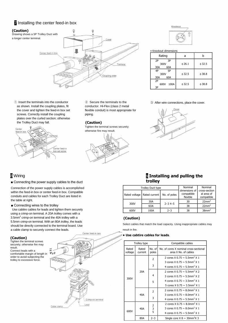
7 Installing the center feed-in box
• Knockout dimensions Rating a b
2P 3P
300V 30A 60A
φ26.1 φ32.5
4P 5P 300V
30A 60A
φ32.5 φ38.8
2P
600V 100A 3P
φ32.5 φ38.8
① Insert the terminals into the conductor
as shown. Install the coupling plates, fit
the cover and tighten the feed-in box set
screws. Correctly install the coupling
plates over the curled section; otherwise
the Trolley Duct may fall.
② Secure the terminals to the
conductor. Hi-Flex (class 2 metal
flexible conduit) is most appropriate for
piping.
(Caution) Tighten the terminal screws securely;
otherwise fire may result.
③ After wire connections, place the cover.
8 Wiring
■ Connecting the power supply cables to the duct
Connection of the power supply cables is accomplished
within the feed-in box or center feed-in box. Compatible
conduits and cables for each Trolley Duct are listed in
the table at right.
■ Connecting wires to the trolley
Use cabtire cables for leads and tighten them securely
using a crimp-on terminal. A 20A trolley comes with a
3.5mm2 crimp-on terminal and the 40A trolley with a
5.5mm crimp-on terminal. With an 80A trolley, the leads
should be directly connected to the terminal board. Use
a cable clamp to securely connect the leads.
(Caution) Tighten the terminal screws securely; otherwise fire may result. Connect leads with a comfortable margin of length in order to avoid subjecting the trolley to excessive force.
9 Installing and pulling the trolley
(Caution) Drawing shows a 5P Trolley Duct with a longer center terminal.
Trolley Duct type Nominal
dimensions of compatible
flexible conduits
Nominal
cross-sectional area of
compatible cables
Rated voltage Rated current No. of poles
300V 30A
2٠3 4٠5 30 22mm2
6OA 38 22mm2
600V 100A 2٠3 38 38mm2
(Caution)
Select cables that match the load capacity. Using inappropriate cables may
result in fire.
• Use cabtire cables for leads.
Trolley type Compatible cables
Rated
voltage
Rated
current
No. of
poles
No. of cores X nominal cross-sectional
area X No. of cables
300V
20A
2
3
2 cores X 0.75 ~ 5.5mm2 X 1
3 cores X 0.75 ~ 5.5mm2 X 1
4 cores X 0.75 ~ 5.5mm2 X 1
4
5
2 cores X 0.75 ~ 5.5mm2 X 2
3 cores X 0.75 ~ 5.5mm2 X 2
4 cores X 0.75 ~ 3.5mm2 X 1
5 cores X 0.75 ~ 3.5mm2 X 1
40A 2
3
2 cores X 0.75 ~ 8.0mm2 X 1
3 cores X 0.75 ~ 8.0mm2 X 1
4 cores X 0.75 ~ 5.5mm2 X 1
600V 40A
2 3 5
2 cores X 0.75 ~ 8.0mm2 X 1
3 cores X 0.75 ~ 8.0mm2 X 1
4 cores X 0.75 ~ 5.5mm2 X 1
80A 2٠3 Single core X 8 ~ 30mm2X 3
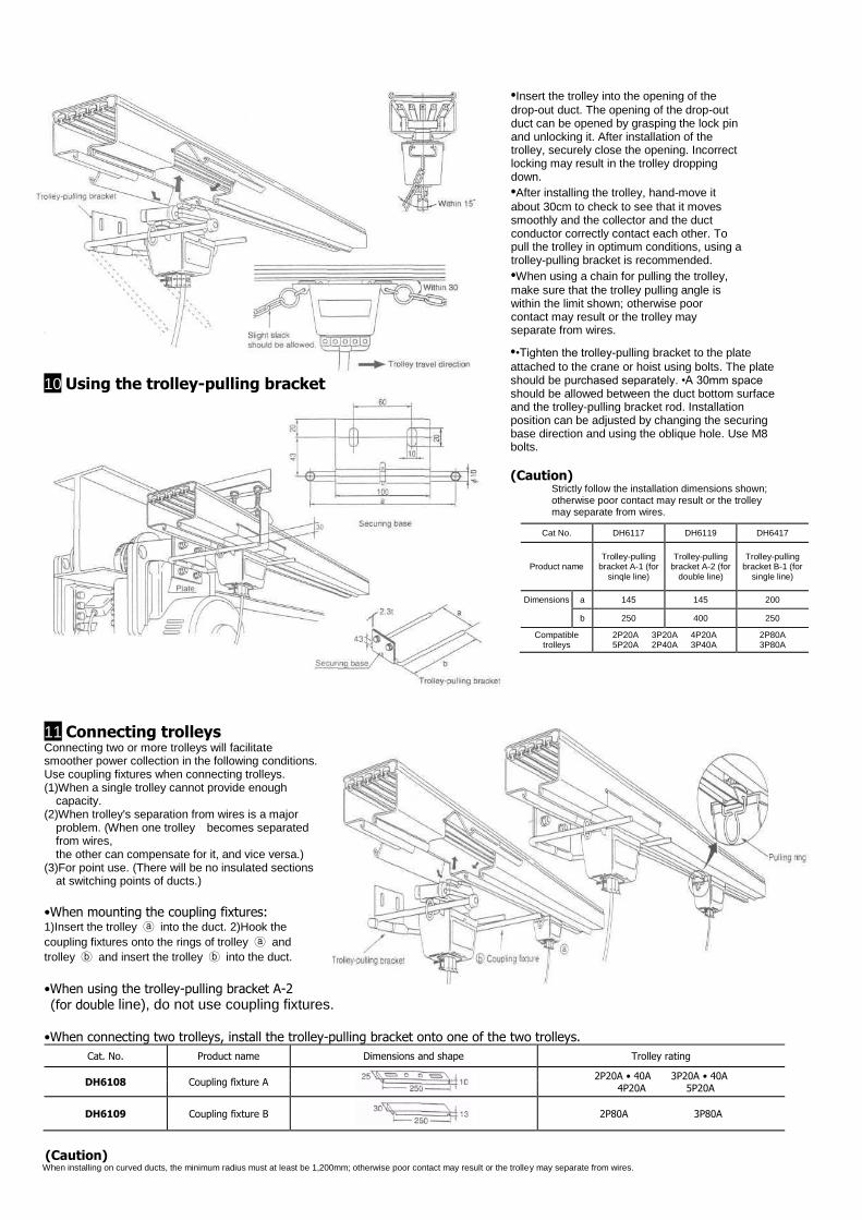
•Insert the trolley into the opening of the
drop-out duct. The opening of the drop-out duct can be opened by grasping the lock pin and unlocking it. After installation of the trolley, securely close the opening. Incorrect locking may result in the trolley dropping down.
•After installing the trolley, hand-move it
about 30cm to check to see that it moves smoothly and the collector and the duct conductor correctly contact each other. To pull the trolley in optimum conditions, using a trolley-pulling bracket is recommended.
•When using a chain for pulling the trolley,
make sure that the trolley pulling angle is within the limit shown; otherwise poor contact may result or the trolley may separate from wires.
10 Using the trolley-pulling bracket
••Tighten the trolley-pulling bracket to the plate
attached to the crane or hoist using bolts. The plate should be purchased separately. •A 30mm space should be allowed between the duct bottom surface and the trolley-pulling bracket rod. Installation position can be adjusted by changing the securing base direction and using the oblique hole. Use M8 bolts.
(Caution) Strictly follow the installation dimensions shown; otherwise poor contact may result or the trolley may separate from wires.
Cat No. DH6117 DH6119 DH6417
Product name Trolley-pulling
bracket A-1 (for sinqle line)
Trolley-pulling bracket A-2 (for
double line)
Trolley-pulling bracket B-1 (for
single line)
Dimensions a 145 145 200
b 250 400 250
Compatible trolleys
2P20A 3P20A 4P20A 5P20A 2P40A 3P40A
2P80A 3P80A
11 Connecting trolleys Connecting two or more trolleys will facilitate smoother power collection in the following conditions. Use coupling fixtures when connecting trolleys. (1)When a single trolley cannot provide enough
capacity. (2)When trolley's separation from wires is a major
problem. (When one trolley becomes separated from wires, the other can compensate for it, and vice versa.)
(3)For point use. (There will be no insulated sections at switching points of ducts.)
•When mounting the coupling fixtures: 1)Insert the trolley ⓐ into the duct. 2)Hook the
coupling fixtures onto the rings of trolley ⓐ and
trolley ⓑ and insert the trolley ⓑ into the duct. •When using the trolley-pulling bracket A-2
(for double line), do not use coupling fixtures. •When connecting two trolleys, install the trolley-pulling bracket onto one of the two trolleys.
Cat. No. Product name Dimensions and shape Trolley rating
DH6108 Coupling fixture A
2P20A • 40A 3P20A • 40A 4P20A 5P20A
DH6109 Coupling fixture B
2P80A 3P80A
(Caution)
When installing on curved ducts, the minimum radius must at least be 1,200mm; otherwise poor contact may result or the trolley may separate from wires.
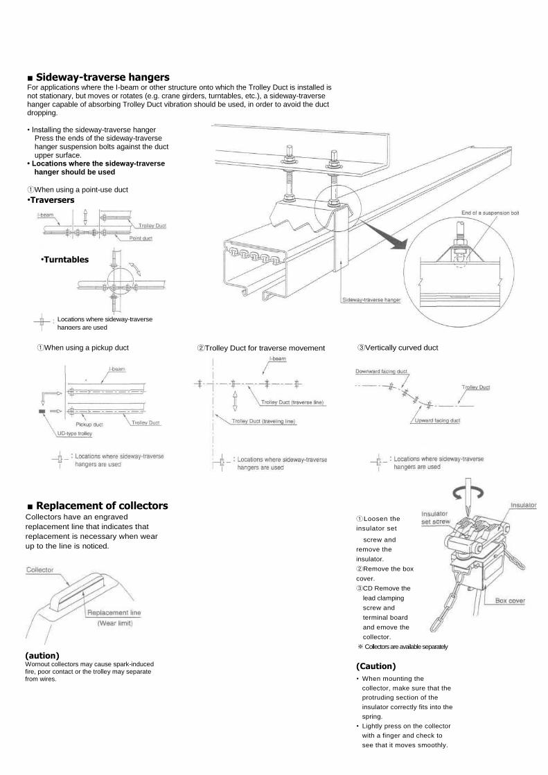
■ Sideway-traverse hangers For applications where the I-beam or other structure onto which the Trolley Duct is installed is not stationary, but moves or rotates (e.g. crane girders, turntables, etc.), a sideway-traverse hanger capable of absorbing Trolley Duct vibration should be used, in order to avoid the duct dropping.
• Installing the sideway-traverse hanger
Press the ends of the sideway-traverse hanger suspension bolts against the duct upper surface.
• Locations where the sideway-traverse hanger should be used
①When using a point-use duct
•Traversers
①When using a pickup duct ②Trolley Duct for traverse movement ③Vertically curved duct
■ Replacement of collectors
Collectors have an engraved
replacement line that indicates that
replacement is necessary when wear
up to the line is noticed.
(aution) Wornout collectors may cause spark-induced fire, poor contact or the trolley may separate from wires.
①Loosen the
insulator set
screw and
remove the
insulator. ②Remove the box
cover. ③CD Remove the
lead clamping
screw and
terminal board
and emove the
collector. ※ Collectors are available separately (Caution)
• When mounting the
collector, make sure that the
protruding section of the
insulator correctly fits into the
spring.
• Lightly press on the collector
with a finger and check to
see that it moves smoothly.
•Turntables
Locations where sideway-traverse
hangers are used
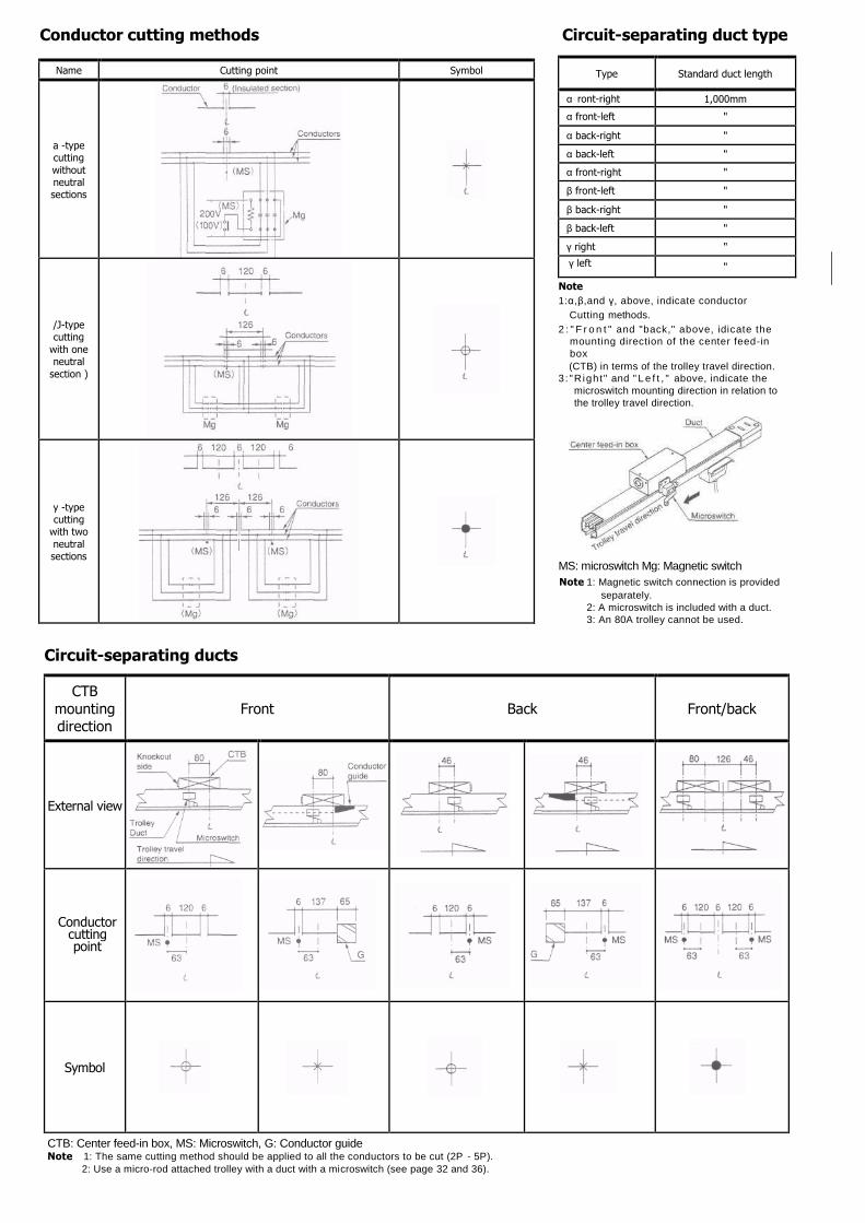
Conductor cutting methods Circuit-separating duct type
Name Cutting point Symbol
a -type cutting
without neutral sections
/J-type cutting
with one neutral
section )
y -type cutting
with two
neutral sections
Type Standard duct length
α ront-right 1,000mm
α front-left "
α back-right "
α back-left "
α front-right "
β front-left "
β back-right "
β back-left "
γ right "
γ left "
Note
1:α,β,and γ, above, indicate conductor
Cutting methods.
2 : " F r o n t " and "back," above, idicate the
mounting direction of the center feed-in
box
(CTB) in terms of the trolley travel direction.
3 : "R ight" and " L e f t , " above, indicate the
microswitch mounting direction in relation to
the trolley travel direction.
MS: microswitch Mg: Magnetic switch
Note 1: Magnetic switch connection is provided
separately.
2: A microswitch is included with a duct.
3: An 80A trolley cannot be used.
Circuit-separating ducts
CTB
mounting direction
Front Back Front/back
External view
Conductor cutting point
Symbol
CTB: Center feed-in box, MS: Microswitch, G: Conductor guide Note 1: The same cutting method should be applied to all the conductors to be cut (2P - 5P).
2: Use a micro-rod attached trolley with a duct with a microswitch (see page 32 and 36).
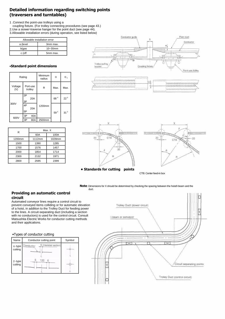
Detailed information regarding switching points (traversers and turntables) 1 .Connect the point-use trolleys using a
coupling fixture. (For trolley connecting procedures (see page 43.) 2.Use a siowe/-traverse hanger for the point duct (see page 44). 3.Allowable installation errors (during operation, see listed below)
Allowable installation error
a (level 3mm max.
b(gas 10~30mm
c (off 5mm max.
•Standard point dimensions
Rating Minimum
radius Φ Φ1
Voltage (V)
Port-use trolley
R Max. Max.
300V
2P 20A
3P
1200mm
68 o 22
o
4P 20A
5P 59 o 31
o
600V 3P 40A
3P 80A 2500mm
R Max. X
60A 100A
1200mm 1112mm 1028mm
1500 1390 1285
1700 1576 1457
2000 1854 1714
2300 2132 1971
2800 2595 2399
• Standards for cutting points CTB: Center feed-in box
Note: Dimensions for X should be determined by checking the spacing between the hoist/I-beam and the duct.
Providing an automatic control
circuit Automated conveyor lines require a control circuit to prevent conveyed items colliding or for automatic elevation of a hoist, in addition to the Trolley Duct for feeding power to the lines. A circuit-separating duct (including a section with no conductors) is used for the control circuit. Consult Matsushita Electric Works for conductor cutting methods and their applications.
•Types of conductor cutting
Name Conductor cutting point Symbol
α-type
cutting
β-type
cutting