Embed Size (px)
Citation preview
PPI Handbook of Polyethylene Pipe
Polyethylene Duct and Conduit
i
Table of Contents
Foreword General 1 Conduit Specifications 1 Applications 1 Advantages of PE Conduit 2 Installation 2 Features 2 Material Selection 4 Physical Properties 4 Cell Classifications 4 Other Important Physical Properties 5 Stabilization 5 Colorants for Conduit 5 Design Considerations 6 General 6 Conduit vs. Pipe 6 Cable Dimension Considerations 6 Conduit Wall Determination 7 Installation Method vs. Short & Long Term Stress 7 Below Ground Installations 8 Open Trench/Continuous Trench 8 Direct Plow 9 Conduit Network Pulling 10 Horizontal Directional Bore 11 Installation Methods 12 General Considerations 12 Mechanical Stress 12 Pulling Tension 12 Bending Radii 12 Underground Installation 13 Trenching Methods 13 Open Trench/Continuous Trench 13 Plowing 14
ii
Plowing Variations 15 Directional Bores 15 Installation into Existing Conduit 15 Above Ground/Aerial 16 Joining Methods 18 Introduction 18 General Provisions 18 Mechanical Fittings 18 Barbed Mechanical Fittings 19 Threaded Mechanical Fittings 19 Compression Fittings 19 Expansion Joints 19 Heat Fusion 19 Butt Fusion Joining 20 Socket Fusion Joining 20 Electrofusion Joining 20 Repair Operations 20 Cable Installation 21 Pulling Cable into Conduit 21 Cable Blowing or Jetting 21 Cable Installed by the Conduit Manufacturer 22 Friction in Conduit Systems 23 Definitions 23 Friction Reduction 23 Field Effects of Friction 24 Placement Planning 25 Special Applications 26 Corrugated Duct 26 Bridge Structures 26 Underwater 26 Premise (Flame Retardant) 27 Electrical/Building Code (Conduit Entry Issues) 28 Armored (Rodent & Mechanical Protection) 28 Multi-Cell Conduit 28 Summary 28 Appendix A – Calculation of Frictional Forces 30
iii
List of Tables
Table 1 Relative Damage Sensitivity vs. Installation Method 8 Table 2 Pipe Stiffness (PS) vs. Crush Strength 10 Table 3 Bending Radii 13
iv
Duct and Conduit FOREWORD
Duct and Conduit is one of the chapters in the Plastics Pipe Institute’s PPI Handbook of Polyethylene Piping. Other topics to be addressed in the handbook will include design of polyethylene piping systems, joining procedures, engineering properties, directional drilling and a variety of related information.
The PPI Handbook of Polyethylene Piping is being produced by the Municipal and Industrial (M&I) Division of PPI. M&I membership consists of major North American manufacturers of polyethylene (PE) pipe and fittings, PE piping materials, machinery, and equipment used for joining and installing PE piping, related test laboratories, and professional organizations.
PPI addresses other applications, such as gas distribution. PPI and its subgroups provide technical and promotional support for the effective use and continued application of thermoplastics pipe and related products, consistent with the best public interest. PPI membership also includes producers of polyvinyl chloride (PVC), chlorinated polyvinyl chloride (CPVC), and cross-linked PE (PEX) piping products and materials.
For a list of other publications available from PPI and/or further information please contact:
The Plastics Pipe Institute www.plasticpipe.org
The information in the publication was prepared by PPI as a service to its members and the
industry. While prepared in good faith and believed to be accurate, PPI, its members, and contributors disclaim all liability for any loss or damage arising from reliance on this information by any person. PPI does not endorse the proprietary products or processes of any manufacturer. Consult the product manufacturer for specific information.
June 2004
v
Chapter 13 – Duct and Conduit
General The general purpose of conduit, or duct, is to provide a clear, protected pathway for a cable, or for smaller conduits, sometimes called innerducts. Advances in cable technologies, as well as the expense of repairing sensitive cable materials like fiber optic cable, have driven preferences for protective conduit over that of direct burial. Polyethylene (PE) conduit provides mechanical protection to fragile cable materials like fiber optic and coaxial cables, as well as protection from moisture or chemicals and even, in some cases, animals. Furthermore, the permanent pathway provided by conduit also facilitates replacement projects or future installations of additional cable or duct.
Buried conduit evolved from terracotta tile, cast concrete and Transit to plastics in the 1960s. Originally, PVC was utilized, but ultimately, PE has emerged as the material of choice due to its distinct advantages in installation options, versatility and toughness.
PE conduit can be installed below ground by a variety of methods, including open trench, plowing, continuous trenching, and directional drilling. Also, its flexibility and availability in continuous coiled lengths facilitates installation into existing conduits or ducts as innerduct. In addition PE conduit provides many aboveground or aerial options.
Conduit Specifications The following specifications are utilized by the industry for the production of Conduit and Raceways:
Telecommunication Conduits – ASTM F2160 Standard Specification for Solid-Wall High Density Polyethylene (HDPE) Conduit Based on Controlled Outside Diameter (OD).
Power Conduits – ASTM F2160 Standard Specification for Solid-Wall High Density Polyethylene (HDPE) Conduit Based on Controlled Outside Diameter (OD)
NEMA TC7 Smooth-wall Coilable Polyethylene Electric Plastic Conduit
Electrical Conduits – UL 651A Type EB and A Rigid PVC Conduit and HDPE Conduit
-- UL 651B Continuous Length HDPE Conduit
Premise Raceways – UL 2024 Optical Fiber Cable Raceway
Applications PE conduit serves two primary industries, communications (telephone, CATV, data transmission) and electrical (power transmission).
In the communications industry, the advent of fiber optic cable has had a tremendous impact due to its significantly higher data-carrying capacity, particularly due to the explosion of the Internet. In telecommunications service (phone, data transmission), fiber optic cable is used, along with traditional copper cable. In cable television service (CATV), fiber optic is also growing rapidly in addition to (or replacing) coaxial cable. This progression toward fiber optic cable has made the
1
need for protection more critical, since these materials are highly sensitive to moisture and mechanical stress. , Damage can be very expensive in terms of interrupted service and replacement costs. Also, these cables are installed in very long, continuous runs which require a clear, protected pathway, as well as a leak-free system for air-assisted (“blow-in”) installations. In addition to fiber optic, coaxial cables have seen improvements to increase bandwidth, making these materials more mechanically sensitive.
In the electrical industry, a critical requirement is on maintaining uninterrupted service, as consumers and businesses are even less tolerant of power outages than they are of phone or CATV service interruptions. Although many direct-buried power cable systems are designed for 30- or 40-year lifetimes, they are susceptible to external influences like rock impingement and often require frequent repairs. Conduit is finding favor over direct burial in these applications due to improved protection, but it must be continuous and facilitate quick repair operations. PE conduit is used to carry both primary (substation to transformer) and secondary (transformer to end-user) cables. Some of these installations also contain fiber optic cables placed alongside the power cables to connect with load-monitoring sensors located throughout the network.
Advantages of PE Conduit High Density Polyethylene (HDPE) is the most commonly used PE material for conduit. HDPE conduit delivers significant physical property advantages over other conduit materials:
• Ductility - tough, HDPE conduit will better resist brittleness with age or cold weather. • Low temperature impact resistance - PE withstands low temperature impact better than
any other material. This is illustrated by impact testing on HDPE conduit conditioned at -4 ° F as compared to other materials conditioned at 73° F
• Permanent flexibility - HDPE conduit bends and flexes without breakage, even with ground heaves or shifts, over a wide range of temperatures.
• Temperature versatility - HDPE conduit can be installed over an ambient temperature range of –30 F to 180 F. Power conductors rated at 90 degrees C and medium voltage cable rated at 105 degrees C are permitted for use with PE Conduit.
Installation Flexible HDPE conduit can be wound onto reels several thousand feet long, does not require manufactured bends and can be easily navigated around unexpected obstructions (in the ground or within existing ducts), simplifying installation. The few joints that are required can be made reliably through a number of options. HDPE conduit is suitable for all methods of duct and cable installation, including trenching, direct plow and installation into existing main pathways (conduit pulling, slip-lining and pipe-bursting). Also, the flexible nature of PE conduit facilitates directional bore installations to breach obstacles like rivers or highways. Cable can consistently be pulled or blown into HDPE duct in great distances and at fast rates due to its low coefficient of friction. Special PE products and accessories are also available for above ground or aerial applications.
2
Features A variety of PE conduit products are available for special applications.
• Multiple ducts of different color/stripe combinations and sizes can be delivered on one common reel, for a more efficient installation.
• Pre-installed Cable-in-Conduit (CIC) saves time and labor by allowing one-step placement of both cable and duct. The integrity of the cable is protected during the installation process by the HDPE duct. Testing prior to and after the duct has been extruded around cable is performed to ensure no performance loss. Cable in Conduit can be provided with fiber, coaxial, twisted pair and electrical cables.
• Corrugated innerduct is flexible, lightweight with a low coefficient of friction.
• Ribbed conduit (longitudinally or spiral) provides friction reduction in cable installation.
• Self-supporting duct includes a suspension strand already built into the duct for greater dimensional stability and ease of installation in the aerial plant. Deployment of ducts aerially allows for enhanced protection for the cable and allows for less costly cable repairs and capacity upgrade options.
3
Section 2: Material Selection
The primary physical property advantages of HDPE conduit are flexibility, ductility and chemical resistance. Other physical attributes critical to the performance of HDPE conduit are tensile strength and stress crack resistance. However, the designing or specifying engineer should be aware that not all PE materials deliver the same level of performance in these areas, and it is critical to ensure that the material meets all the demands of the installation and service conditions. This section will briefly discuss these material considerations, but a more thorough discussion of PE technology is provided in the Chapter on Engineering Properties of Polyethylene in The PPI Polyethylene Handbook.
Physical Properties
Cell Classification The Cell Classification (ASTM D 3350) is a 6-digit numeric “code” which describes a HDPE conduit material’s performance level in six key physical characteristics. This 6-digit classification often includes a single letter suffix representing a color or UV stabilizer category. This cell classification is used in specifications such as ASTM F2160 Standard Specification for Solid Wall High Density Polyethylene (HDPE) Conduit Based on Controlled Outside Diameter (OD). Each property is broken into 4-6 specific performance ranges.
Density. HDPE density generally has the greatest effect on many physical properties. For example, higher densities favor increased tensile strength and stiffness, while, lower densities generally favor impact resistance, and flexibility and stress crack resistance. Density also affects coefficient of friction (COF – see Section 7), with higher density typically related to lower COF. Therefore, some degree of compromise may be necessary to balance properties required for a particular application.
Melt Index. Melt Index (MI), a measurement of a polymer’s molten flow properties (ASTM D 1238), is related to molecular weight, or the length of the individual polymer chains. Generally, lower melt indices represent higher molecular weights while higher values indicate lower molecular weights. For any given PE resin, a lower melt index (higher molecular weight) will normally have superior physical properties.
Flexural Modulus. Flexural modulus is a measure of a plastic’s stiffness, or its resistance to bending or deflection under applied load. In HDPE conduit, these stiffness characteristics generally affect load-bearing capability, bending radius, and tendency to ovalize (when coiled or bent). Flexural modulus should be taken into account when determining the appropriate wall thickness for an installation.
Tensile Strength/Yield Strength: Tensile yield strength, or the point at which a stress causes a material to deform beyond its elastic region (irreversible deformation), is a critical property for many conduit installation methods involving pulling (e.g., directional drilling). Yield strength can limit the rates or lengths of such installations (see Section 3: Design Considerations), and it is an important consideration in determining allowable pull loads. It is important to note that both flexural modulus and tensile strength are affected by temperature (both decrease with increasing temperature).
Slow Crack Growth. ASTM D1693 Environmental Stress Cracking Resistance (ESCR) or ASTM F1473 Polyethylene Notched Tensile (PENT) can measure properties of slow crack growth. For PE conduit applications, ESCR is utilized. As one of the most important properties affecting the service life of PE conduit, stresses due to bends and rock impingement can cause inferior conduit materials to crack and fail, particularly at higher
4
temperatures. ESCR is a laboratory test, which measures a material’s ability to resist cracking under these conditions. As mentioned above, higher densities generally have a negative effect on ESCR, and, as a general practice, base resins with densities below 0.950 have ESCR properties suitable for conduit applications.
Hydrostatic Strength Classification: The hydrostatic strength classification describes the material’s resistance to failure under internal pressure; this property is primarily used for pressure piping applications and is not required for conduit. HDPE conduit materials are represented by a “0” (not pressure rated) in this category.
Other Important Physical Properties Chemical Resistance. PE is highly resistant to a wide range of chemical agents even at elevated temperatures. However, when installing in potentially aggressive environments, the user should refer to PPI Technical Report TR-19, Thermoplastic Piping for the Transport of Chemicals, which provides chemical resistance data for PE with a wide range of chemicals.
Impact Resistance. Impact resistance is related to the pipe’s ability to absorb impact and resist cracking during handling and installation, particularly in cold weather. An advantage of HDPE over many other materials is its ductility at low temperatures. For example, PE’s glass transition temperature (the temperature below which it is more brittle and glassy) is well below 0 F, at approximately -166°F (~-110°C), while for PVC it is well above room temperature, at about 176°F (~80°C). Like ESCR, impact resistance is strongly influenced by density, with lower densities generally favoring greater impact resistance.
There are a number of impact tests for materials, like Izod or Charpy (see Chapter on Engineering Properties of PPI Polyethylene Handbook), but generally finished pipe and fittings are tested by a falling weight (tup) impact test (for example, ASTM D2444) at low temperature -- typically -4°F (-20°C). This test, commonly used in Quality Assurance, is a pass/fail test, in which any cracking or breaking is considered a failure.
Stabilization Unprotected PE, like virtually all other polymers, is vulnerable to degradation due to prolonged exposure to heat, oxygen or ultraviolet (UV) radiation, resulting in embrittlement and reduced service life. To prevent these damaging effects, PE conduit materials are typically formulated with a variety of stabilizing additives, ranging from antioxidants to UV stabilizers, to maintain required long-term performance. For a more in-depth discussion on both antioxidants and UV protection, see the Chapter on Engineering Properties PPI Handbook of Polyethylene Pipe. Regardless of the type of UV protection used, the conduit must be adequately protected from UV attack to withstand normal storage conditions and special use intervals. Adequate protection for conduit destined for underground installation is to provide for at least one year’s protection from outdoor storage. If longer storage times are possible or anticipated, the user may specify additional stabilization, or, preferably, should provide for a covered storage environment. Otherwise, if the conduit exceeds one year of UV exposure, it should be tested to ensure it meets all physical property requirements (cell classification, impact resistance) prior to installation.
5
The most common means for UV protection is to employ carbon black at a minimum loading of 2%. For long-term aerial exposure in self-supporting Figure-8 duct designs, due to the heightened mechanical stress level, the carbon black should be more finely divided and dispersed, having an average particle size of less than or equal to 20 nanometers, in accordance with ASTM F 2160.
PE non-black materials, however, require special stabilizers in addition to their normal pigments, generally UV blockers or Hindered Amine Light Stabilizers (HALS).
Colorants for Conduit PE conduit is produced in a variety of solid and striped colors, which serve to help identify the duct for either its end use application (e.g., fiber optic cable, power, etc.) or owner. In determining the color of the conduit, its striping or the marking of the conduit or a combination thereof, it is recommended for safety reasons that the color yellow not be utilized since this is the uniform color code for natural gas applications.
Section 3: Design Considerations
Conduit vs. Pipe In general, plastic conduits and plastic pipes are very similar in structure and composition, but deployment is where they differ.
Conduits do not have long-term internal pressure—
External forces are unchecked; if ovalized during installation, it may not recover during service.
Long-term stress rupture is not a factor (Hydrostatic Design Basis is not required in material selection).
Conduit ID is chosen by cable occupancy, where internal clearances are critical; whereas, for piping applications ID is based on volumetric flow requirements.
Path of installation for conduit is very important – radius of curvature, vertical and horizontal path deviations (undulations) and elevation changes all significantly affect cable placement.
Cable Dimension Considerations Determination of a conduit’s dimensions begins with the largest cable, or group of cables or innerducts, intended for occupancy. From a functional viewpoint, selection of diameter can be broken down into the following general considerations:
1. The inside diameter of the conduit is determined by the cable diameter and placement method (pulling or air-assisted pushing).
2. Pulling cables into underground conduits requires sufficient free clearance and is typically further distinguished by classifying the cables into two groups: power and coax (short lengths) and fiber (long lengths). Additionally, electrical cable fill is controlled by the National Electric Code (Chapter 9), whereas, dielectric, or fiber optic cables, are not.
3. Long pulling lengths require low volume fill, i.e. 36% max.
4. Short pulling lengths may be filled up to 53%, or up to the latest NEC limitations for groups of cables.
5. Push-blow installation methods for long length fiber cables utilize higher volume fills, i.e. up to 70% max.
6
6. Innerducts are smaller diameter conduits, intended for placement into larger conduits or casings. Their purpose is to subdivide the larger conduit space into discrete continuous pathways for incorporation of fiber optic cables. Diameters of conduits and innerducts are often specially designed to maximize the conduit fill.
Using these guidelines, one can determine the minimum ID of the conduit or innerduct. When over-sizing a conduit for power, coaxial or multi-pair telecom cables, the more room the better. This rule does not necessarily apply for push-blow methods of installation. Here, it is found to be more difficult to push a cable with additional clearance since a cable tends to form a helix, which transfers some of the axial load laterally into the wall causing friction. The air velocity moving over the cable can also be maximized with a minimum volume of air when the free volume is low. Higher air velocities result in improved drag forces on the cable, thus aiding with its placement.
Conduit Wall Determination Conduit and duct products come in a wide range of sizes, spanning 1/4-inch (5mm) to 24-inch (610mm) bore casings. The standard dimension ratio, SDR, of a conduit is defined as the ratio of the average conduit diameter divided by the minimum wall thickness. Wall thickness typically ranges between SDR 9 to SDR 17 (larger SDR numbers indicate a thinner wall thickness). Conventions exist that work off of either the average outside diameter (SDR) or the average inside diameter (SIDR). Internally sized (SIDR) are usually chosen when the inside diameter clearance must be very carefully controlled. This usually does not apply to most duct installations because, as noted above, the free clearance between the cable and the inner wall of the conduit is not usually that close. Bore casings, on the other hand, offer situations that can benefit from close ID control because many times several innerducts are tightly fit into a casing. In this latter case, the conduit wall can be increased or decreased relative to service conditions without jeopardizing the inside clearance fit. Internally sized dimension tables tend to preserve the minimum ID above the nominal conduit size, whereas, externally sized conduits often fall below the nominal ID as the wall thickness increases. For most conduit installations, SDR sizing is utilized because the OD control lends itself to better joint formation using external couplers. This becomes very important when air-assisted placement methods are used for placing the cable. On the other hand, large diameter conduits (4” and above) typically undergo butt fusion as a means of joining. Determination of the wall thickness becomes a function of either the method by which the conduit is placed, or the nature of environmental stresses that it will be exposed to over the service life. ASTM F 2160, “Standards Specification for Solid Wall High Density Polyethylene (HDPE) Conduit Based on Controlled Outside Diameter (OD)”, explains the conduit sizing systems fully.
Installation Method vs. Short Term and Long Term Stress The viscoelastic nature of HDPE results in differences in the observed mechanical properties as a function of time (and/or temperature). The apparent stress/strain behavior of the material is time dependent under the influence of a sustained load. This is referred to as “creep” properties. In this regard, we can distinguish between “short-term” properties, such as those exhibited during a laboratory tensile test at a strain (stretching) rate of 2 inches per minute, as compared with “long-term” properties typical of conduit placement and sustained service loads.
Knowledge of the load-bearing capability of HDPE as a function of loading rate allows one to select appropriate strength values to substitute into design equations. Loads are applied to conduits both by the environment that they are placed into and by the placement means under which they’re installed; the chief difference being the duration over which the load is applied. For example, a
7
common means to install multiple conduits is to directly plow them into the ground using either a railroad plow or tractor-drawn plow. During this installation process, a certain amount of bending and tensile stress is encountered over a rather short period of time (only seconds to minutes). Whereas, after the plow cavity collapses about the conduit, the ground continues to settle upon stones that may be pressing directly against the conduit, thus setting up a long-term compressive load. For this application, we see that we would require both long-term and short-term modulii to assess the deflection resistance. Initially the conduit may offer resistance to ovalization, but in time, the resin may yield under the sustained load, resulting in a reduced pathway for the cable.
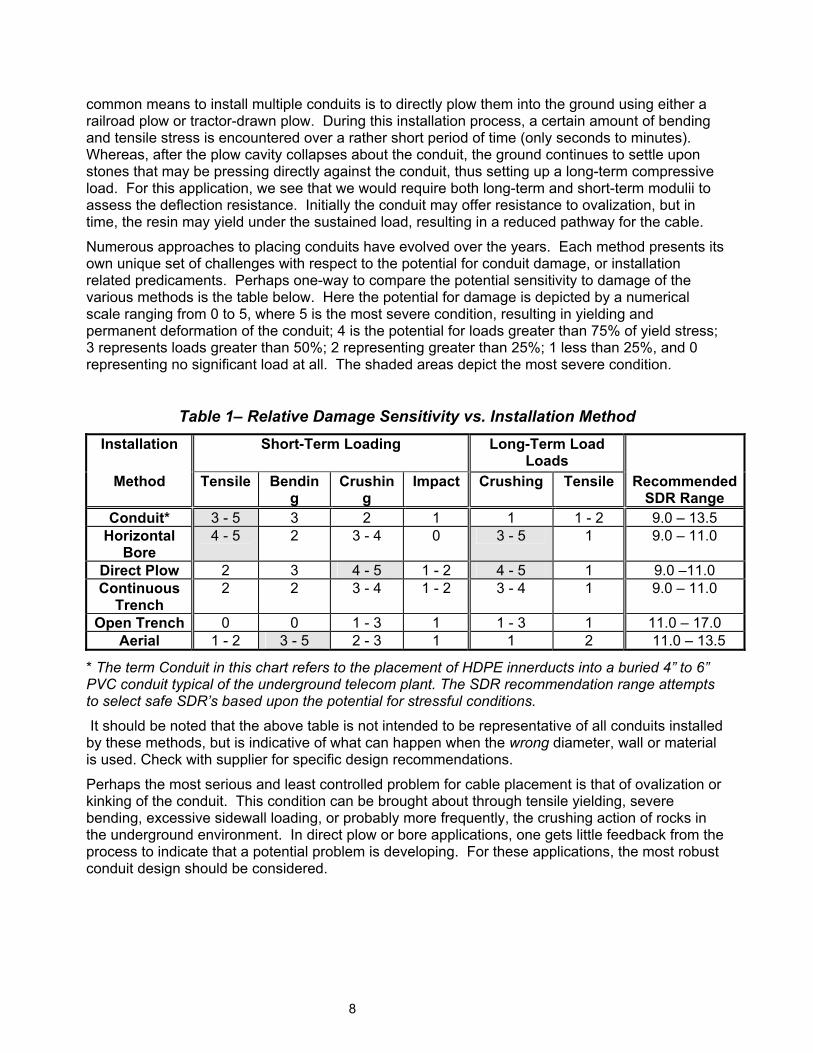
Numerous approaches to placing conduits have evolved over the years. Each method presents its own unique set of challenges with respect to the potential for conduit damage, or installation related predicaments. Perhaps one-way to compare the potential sensitivity to damage of the various methods is the table below. Here the potential for damage is depicted by a numerical scale ranging from 0 to 5, where 5 is the most severe condition, resulting in yielding and permanent deformation of the conduit; 4 is the potential for loads greater than 75% of yield stress; 3 represents loads greater than 50%; 2 representing greater than 25%; 1 less than 25%, and 0 representing no significant load at all. The shaded areas depict the most severe condition.
Table 1– Relative Damage Sensitivity vs. Installation Method
Installation Short-Term Loading
Long-Term Load Loads
Method Tensile Bending
Crushing
Impact Crushing Tensile Recommended SDR Range
Conduit* 3 - 5 3 2 1 1 1 - 2 9.0 – 13.5 Horizontal
Bore 4 - 5 2 3 - 4 0 3 - 5 1 9.0 – 11.0
Direct Plow 2 3 4 - 5 1 - 2 4 - 5 1 9.0 –11.0 Continuous
Trench 2 2 3 - 4 1 - 2 3 - 4 1 9.0 – 11.0
Open Trench 0 0 1 - 3 1 1 - 3 1 11.0 – 17.0 Aerial 1 - 2 3 - 5 2 - 3 1 1 2 11.0 – 13.5
* The term Conduit in this chart refers to the placement of HDPE innerducts into a buried 4” to 6” PVC conduit typical of the underground telecom plant. The SDR recommendation range attempts to select safe SDR’s based upon the potential for stressful conditions.
It should be noted that the above table is not intended to be representative of all conduits installed by these methods, but is indicative of what can happen when the wrong diameter, wall or material is used. Check with supplier for specific design recommendations.
Perhaps the most serious and least controlled problem for cable placement is that of ovalization or kinking of the conduit. This condition can be brought about through tensile yielding, severe bending, excessive sidewall loading, or probably more frequently, the crushing action of rocks in the underground environment. In direct plow or bore applications, one gets little feedback from the process to indicate that a potential problem is developing. For these applications, the most robust conduit design should be considered.
8
Below Ground Installations
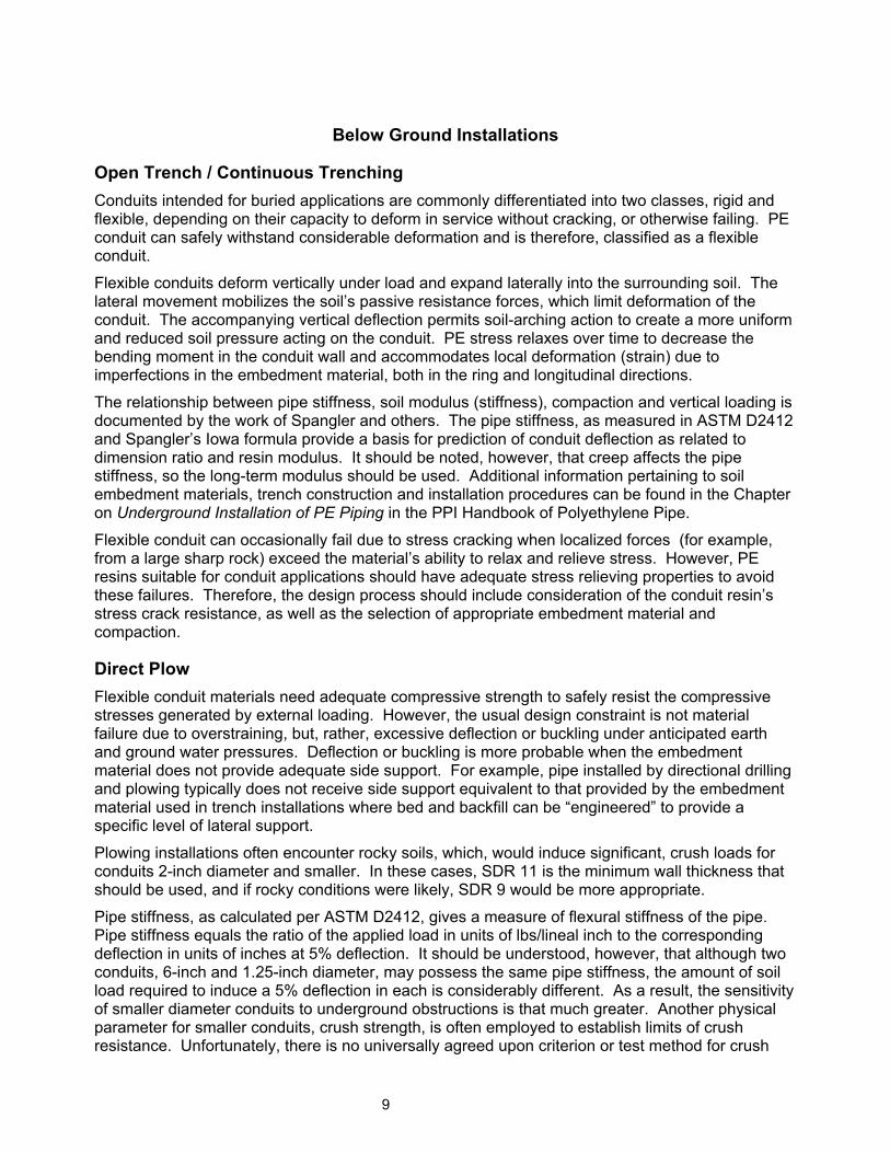
Open Trench / Continuous Trenching Conduits intended for buried applications are commonly differentiated into two classes, rigid and flexible, depending on their capacity to deform in service without cracking, or otherwise failing. PE conduit can safely withstand considerable deformation and is therefore, classified as a flexible conduit.
Flexible conduits deform vertically under load and expand laterally into the surrounding soil. The lateral movement mobilizes the soil’s passive resistance forces, which limit deformation of the conduit. The accompanying vertical deflection permits soil-arching action to create a more uniform and reduced soil pressure acting on the conduit. PE stress relaxes over time to decrease the bending moment in the conduit wall and accommodates local deformation (strain) due to imperfections in the embedment material, both in the ring and longitudinal directions.
The relationship between pipe stiffness, soil modulus (stiffness), compaction and vertical loading is documented by the work of Spangler and others. The pipe stiffness, as measured in ASTM D2412 and Spangler’s Iowa formula provide a basis for prediction of conduit deflection as related to dimension ratio and resin modulus. It should be noted, however, that creep affects the pipe stiffness, so the long-term modulus should be used. Additional information pertaining to soil embedment materials, trench construction and installation procedures can be found in the Chapter on Underground Installation of PE Piping in the PPI Handbook of Polyethylene Pipe.
Flexible conduit can occasionally fail due to stress cracking when localized forces (for example, from a large sharp rock) exceed the material’s ability to relax and relieve stress. However, PE resins suitable for conduit applications should have adequate stress relieving properties to avoid these failures. Therefore, the design process should include consideration of the conduit resin’s stress crack resistance, as well as the selection of appropriate embedment material and compaction.
Direct Plow Flexible conduit materials need adequate compressive strength to safely resist the compressive stresses generated by external loading. However, the usual design constraint is not material failure due to overstraining, but, rather, excessive deflection or buckling under anticipated earth and ground water pressures. Deflection or buckling is more probable when the embedment material does not provide adequate side support. For example, pipe installed by directional drilling and plowing typically does not receive side support equivalent to that provided by the embedment material used in trench installations where bed and backfill can be “engineered” to provide a specific level of lateral support.
Plowing installations often encounter rocky soils, which, would induce significant, crush loads for conduits 2-inch diameter and smaller. In these cases, SDR 11 is the minimum wall thickness that should be used, and if rocky conditions were likely, SDR 9 would be more appropriate.
Pipe stiffness, as calculated per ASTM D2412, gives a measure of flexural stiffness of the pipe. Pipe stiffness equals the ratio of the applied load in units of lbs/lineal inch to the corresponding deflection in units of inches at 5% deflection. It should be understood, however, that although two conduits, 6-inch and 1.25-inch diameter, may possess the same pipe stiffness, the amount of soil load required to induce a 5% deflection in each is considerably different. As a result, the sensitivity of smaller diameter conduits to underground obstructions is that much greater. Another physical parameter for smaller conduits, crush strength, is often employed to establish limits of crush resistance. Unfortunately, there is no universally agreed upon criterion or test method for crush
9
testing. Typically, the conduits are subjected to an increasing load, similarly applied as in ASTM D2412, but to a far greater deflection; on the order of 25 to 50% of the inside diameter. This deflection-limiting load is then reported on a per-foot basis.
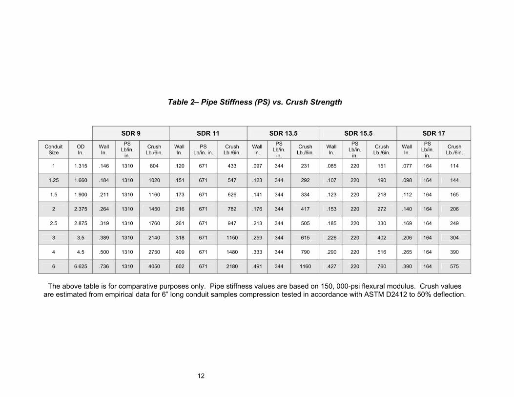
The table below illustrates the difference in the load required to induce a 5% deflection in conduits having different diameters but common pipe stiffness values. These values were generated assuming a flexural modulus of 150,000 psi for the resin. Units for pipe stiffness are in pounds / inch of length / inch of deflection, whereas, those for the crush are presented as pounds per foot. It is apparent that a fixed external load more easily deflects smaller diameter conduits. It is also important to remember that in long-term loading, the resin will maintain only about 22 to 25% of its original modulus, thus, smaller, thin-wall conduits can be quite susceptible to localized loads brought about by buried obstructions.
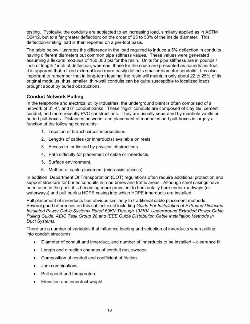
Conduit Network Pulling In the telephone and electrical utility industries, the underground plant is often comprised of a network of 3”, 4”, and 6” conduit banks. These “rigid” conduits are composed of clay tile, cement conduit, and more recently PVC constructions. They are usually separated by manhole vaults or buried pull-boxes. Distances between, and placement of manholes and pull-boxes is largely a function of the following constraints:
1. Location of branch circuit intersections.
2. Lengths of cables (or innerducts) available on reels.
3. Access to, or limited by physical obstructions.
4. Path difficulty for placement of cable or innerducts.
5. Surface environment.
6. Method of cable placement (mid-assist access).
In addition, Department Of Transportation (DOT) regulations often require additional protection and support structure for buried conduits in road bores and traffic areas. Although steel casings have been used in the past, it is becoming more prevalent to horizontally bore under roadways (or waterways) and pull back a HDPE casing into which HDPE innerducts are installed.
Pull placement of innerducts has obvious similarity to traditional cable placement methods. Several good references on this subject exist including Guide For Installation of Extruded Dielectric Insulated Power Cable Systems Rated 69KV Through 138KV, Underground Extruded Power Cable Pulling Guide, AEIC Task Group 28 and IEEE Guide Distribution Cable Installation Methods In Duct Systems.
There are a number of variables that influence loading and selection of innerducts when pulling into conduit structures:
• Diameter of conduit and innerduct, and number of innerducts to be installed – clearance fit
• Length and direction changes of conduit run, sweeps
• Composition of conduit and coefficient of friction
• Jam combinations
• Pull speed and temperature
• Elevation and innerduct weight
10
11
Horizontal Directional Bore For directional drilling the design process should include consideration of tensile forces and bend radii created during these processes. Flexible conduits installed in continuous lengths are susceptible to potential tensile failures when pulled into place, so allowable tensile forces should be determined to avoid neck-down from tensile yield. The engineer should also account for the conduit’s allowable bend radius, especially on bends with no additional support given to the conduit, to prevent ovalization and kinking from installation. . For additional information, please refer to the Chapter on Horizontal Directional Drilling in PPI Handbook of Polyethylene Pipe.
12
Table 2– Pipe Stiffness (PS) vs. Crush Strength
SDR 9 SDR 11 SDR 13.5 SDR 15.5 SDR 17
Conduit Size
OD In.
Wall In.
PS Lb/in.
in.
Crush Lb./6in.
Wall In.
PS Lb/in. in.
Crush Lb./6in.
Wall In.
PS Lb/in.
in.
Crush Lb./6in.
Wall In.
PS Lb/in.
in.
Crush Lb./6in.
Wall In.
PS Lb/in.
in.
Crush Lb./6in.
1 1.315 .146 1310 804 .120 671 433 .097 344 231 .085 220 151 .077 164 114
1.25 1.660 .184 1310 1020 .151 671 547 .123 344 292 .107 220 190 .098 164 144
1.5 1.900 .211 1310 1160 .173 671 626 .141 344 334 .123 220 218 .112 164 165
2 2.375 .264 1310 1450 .216 671 782 .176 344 417 .153 220 272 .140 164 206
2.5 2.875 .319 1310 1760 .261 671 947 .213 344 505 .185 220 330 .169 164 249
3 3.5 .389 1310 2140 .318 671 1150 .259 344 615 .226 220 402 .206 164 304
4 4.5 .500 1310 2750 .409 671 1480 .333 344 790 .290 220 516 .265 164 390
6 6.625 .736 1310 4050 .602 671 2180 .491 344 1160 .427 220 760 .390 164 575
The above table is for comparative purposes only. Pipe stiffness values are based on 150, 000-psi flexural modulus. Crush values
are estimated from empirical data for 6” long conduit samples compression tested in accordance with ASTM D2412 to 50% deflection.
Section 4: Installation Methods This section will discuss various conduit installation options in general terms and should not be interpreted as a step-by-step guide or “operations manual.” The user should contact the equipment manufacturer for more detailed instruction, as operating procedures will vary with equipment.
NOTE: The consequences of striking gas or power lines (above and below ground) during installation can be dangerous, possibly deadly. Before digging, it is critical to ensure that all existing underground service lines (gas, water, power, etc) in the vicinity are located and marked. It is recommended to contact the local “Call Before You Dig” agency to ensure these provisions are made. Furthermore, prior to installation, consult NEC, NFPA and NESC codes, as well as any applicable local codes.
General Considerations
Mechanical Stress Regardless of the installation method, mechanical stress is of great concern during conduit placement. Exceeding the maximum allowable pulling tension or the minimum allowable bending radii can damage conduit. Consult the conduit supplier for allowable pulling tensions.
Pulling Tension During conduit pulling placement, attention should be given to the number of sweeps, bends or offsets and their distribution over the pull.
Tail loading is the tension in the cable caused by the mass of the conduit on the reel and reel brakes. Tail loading is controlled by two methods. Using minimal braking during the pay-off of the conduit from the reel at times can minimize tension, no braking is preferred. Rotating the reel in the direction of pay-off can also minimize tail loading.
Breakaway swivels should be placed on the conduit to ensure that the maximum allowable tension for that specific conduit type is not exceeded. The swivel is placed between the winch line and pulling grip. A breakaway swivel is required for each conduit.
Bending Radii Conduit is often routed around corners during placement and pulling tension must be increased to complete the pull. It is important to determine the minimum radius to which the conduit can be bent without mechanically degrading the performance of the conduit. See Chart Below.
13
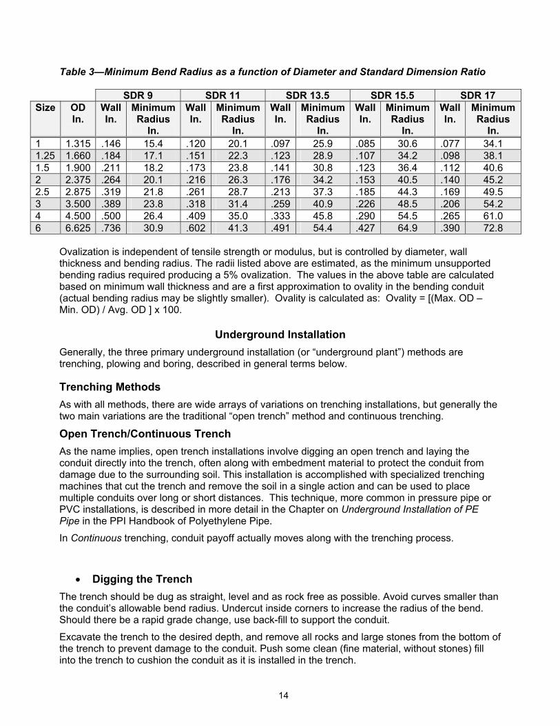
Table 3—Minimum Bend Radius as a function of Diameter and Standard Dimension Ratio
SDR 9 SDR 11 SDR 13.5 SDR 15.5 SDR 17 Size OD
In. Wall In.
Minimum Radius
In.
Wall In.
Minimum Radius
In.
WallIn.
Minimum Radius
In.
WallIn.
Minimum Radius
In.
WallIn.
Minimum Radius
In. 1 1.315 .146 15.4 .120 20.1 .097 25.9 .085 30.6 .077 34.1 1.25 1.660 .184 17.1 .151 22.3 .123 28.9 .107 34.2 .098 38.1 1.5 1.900 .211 18.2 .173 23.8 .141 30.8 .123 36.4 .112 40.6 2 2.375 .264 20.1 .216 26.3 .176 34.2 .153 40.5 .140 45.2 2.5 2.875 .319 21.8 .261 28.7 .213 37.3 .185 44.3 .169 49.5 3 3.500 .389 23.8 .318 31.4 .259 40.9 .226 48.5 .206 54.2 4 4.500 .500 26.4 .409 35.0 .333 45.8 .290 54.5 .265 61.0 6 6.625 .736 30.9 .602 41.3 .491 54.4 .427 64.9 .390 72.8
Ovalization is independent of tensile strength or modulus, but is controlled by diameter, wall thickness and bending radius. The radii listed above are estimated, as the minimum unsupported bending radius required producing a 5% ovalization. The values in the above table are calculated based on minimum wall thickness and are a first approximation to ovality in the bending conduit (actual bending radius may be slightly smaller). Ovality is calculated as: Ovality = [(Max. OD – Min. OD) / Avg. OD ] x 100.
Underground Installation
Generally, the three primary underground installation (or “underground plant”) methods are trenching, plowing and boring, described in general terms below.
Trenching Methods As with all methods, there are wide arrays of variations on trenching installations, but generally the two main variations are the traditional “open trench” method and continuous trenching.
Open Trench/Continuous Trench As the name implies, open trench installations involve digging an open trench and laying the conduit directly into the trench, often along with embedment material to protect the conduit from damage due to the surrounding soil. This installation is accomplished with specialized trenching machines that cut the trench and remove the soil in a single action and can be used to place multiple conduits over long or short distances. This technique, more common in pressure pipe or PVC installations, is described in more detail in the Chapter on Underground Installation of PE Pipe in the PPI Handbook of Polyethylene Pipe.
In Continuous trenching, conduit payoff actually moves along with the trenching process.
• Digging the Trench The trench should be dug as straight, level and as rock free as possible. Avoid curves smaller than the conduit’s allowable bend radius. Undercut inside corners to increase the radius of the bend. Should there be a rapid grade change, use back-fill to support the conduit.
Excavate the trench to the desired depth, and remove all rocks and large stones from the bottom of the trench to prevent damage to the conduit. Push some clean (fine material, without stones) fill into the trench to cushion the conduit as it is installed in the trench.
14
Supplemental trenches should be made to all offset enclosure locations. Trench intersections should be excavated to provide adequate space to make sweeping bends in the conduit.
Fill the trench and compact as required. Tamp the trench to provide compaction that will prevent the trench backfill from settling.
• Placing the conduit An important consideration for open-trench installations of PE conduit is that conduit should be straightened to remove any residual “coil memory”, which can create a tortuous path for the cable and create significant challenges to cable installation. Conduit pay-off can be accomplished by pulling the conduit into the trench from a stationary reel or by laying the conduit into the trench from a moving reel, usually attached to a trailer.
Spacers should be used when placing multiple ducts in a trench. Spacers prevent the ducts from twisting over and around each other. By keeping the ducts in straight alignment, cable-pulling tensions are reduced. When water is present in the trench or when using extremely wet concrete slurry floating of the conduit can be restricted through the use of the spacers.
• Backfilling It is best to place the best quality soil directly on and around the conduit. DO NOT place large rocks directly on the conduit. Allow at least 2 – 4 inches (5 – 10 cm) of clean, uniform soil to cushion the conduit.
A good practice to insure long-term protection of underground facilities is to utilize sand for padding the conduit. It provides a more stable environment for the conduit, prohibiting damage from rocks and allowing water to drain away from conduit easily. More importantly is the protection it can provide during future excavation near your facilities. The apparent change in soil condition provides warning that there is a utility buried there. This should not replace the practice of placing warning tape, but rather should serve as a supplement. During backfill warning tape should be placed typically 1 to 3 feet above the conduit.
Plowing Plowing is the preferred installation for long continuous runs where space permits, for example, in rural areas. Plowing installations use a plow blade (pulled by a tractor or mounted to a railroad car) to split the earth and place the cable at the required depth through a feed tube located directly on the plow blade. The key distinction between plowing and continuous trenching is that trenching involves the actual removal of soil from the trench, whereas plowing only displaces soil while lying in the conduit.
Consult the equipment manufacturer for specific recommendations on plow blade and feed tube designs. It is strongly recommend to have a professionally engineered single or double feed tube plow blade with a tube at least 0.5 inch (1.25 cm) larger than the largest conduit size and a radius no smaller than the minimum bend radius of the largest conduit size. It is recommended that DR 11 or DR 9 be used depending on conditions and conduit diameter.
Local regulation may require that warning tape be plowed in with the cable. Most plow manufacturers make plow blades that bury cable and tape at the same time.
Plowing Variations There are several variations of plowing installations. A few are described briefly below:
• Vibratory plowing. This method uses a vibrating blade and, may allow use of a smaller tractor than that used for static plowing.
15
• Rip and Plow. This method may be required when significant obstructions (for example, roots) are anticipated and uses an additional lead plow (without conduit) to rip the ground and clear obstructions several hundred yards ahead of the primary plow with conduit.
• Pull plows method. Instead of installing from a reel traveling with the plow, conduit is pulled from a stationery reel behind the plow through the plowed trench.
Directional Bores Directional boring allows the installation of conduit under obstacles that do not allow convenient plowing or trenching installations, for example rivers or highways. This unique installation method, which capitalizes on a primary strength of PE conduit, its flexibility, can be accomplished over very long distances.
Directional boring is accomplished using a steer able drill stem to create a pathway for the conduit. The equipment operator can control the depth and direction of the boring. A detailed discussion of this installation method is presented in the Chapter on Polyethylene Pipe for Horizontal Directional Drilling in the PPI Handbook of Polyethylene Pipe. Also, consult the equipment supplier for detailed operating procedures and safety precautions.
It is recommended that DR 11 or DR 9 be used depending on conditions and conduit diameter.
Installation into Existing Conduit Conduit (or multiple conduits) is often pulled into existing conduit systems as innerduct.
NOTE: ALWAYS test and ventilate manholes prior to entering into them and follow OSHA confined space requirements.
• Proofing An important step that should be taken prior to this type of installation is “proofing” the existing conduit to ensure that all obstructions are cleared and that conduit continuity and alignment is good. It is recommended that a rigid mandrel roughly 90% of the inner diameter of the conduit be used to perform the proof. Proofing conduit is typically performed by pushing a fiberglass fish with a rigid mandrel attached to the end of it through the conduit. Any problem areas should be felt by the person pushing the fiberglass fish and should then be marked on the fish so that the distance to the problem is recorded and if necessary can be located for repair with greater ease. If the fiberglass fish makes its way through the conduit without any difficulties experienced, then the conduit has “proofed out” and no repairs should be necessary.
Before placement of the innerduct inside the conduit can be started it is important to have all of the necessary equipment to protect the innerduct. The use of sheaves, bending shoes, rolling blocks (45 and 90 degrees) and straight pulleys are required for protection of the innerduct during installation. It is important that they all meet the proper radius for the innerduct size. The use of a pulling lubricant will greatly reduce the tension and stress on the innerduct when pulling innerduct into an existing conduit. Ball bearing swivels are needed for attaching the winch line to the innerduct harness system.
• Mid-Assists On long routes and routes with many turns in them it is important to consider the selection of mid-assist locations. There are different ways of providing mid-assist for innerduct pulls. Typically the use of a winch is required such as a capstan or vehicle drum winch. The introduction of mid-assist capstan winches has made innerduct pulling an easier task, requiring less manpower and
16
communication than traditional drum winching involves. More importantly it provides greater production capabilities.
• After pulling The stress of pulling innerduct through existing conduit will vary with the length of the route and the number of turns it has to make, as well as the condition of the conduit it is being pulled into and the amount of lubrication used. The effects of the stress will cause the innerduct to elongate (or stretch) in proportion to the amount of stress but should be less than 2% of the total length placed. Due to this effect, it is important to pull past the conduit system slightly to compensate for recovery to the original length. An allowance of at least one hour needs to be given for the innerduct to “relax” before cutting and trimming it.
Above Ground/Aerial
There are many applications for aerial conduit, which include but are not limited to road crossings, rail crossings, trolley line crossings, and water crossings. They provide for efficient means of supporting cable that can easily be replaced and/or allow for the addition of cables without requiring encroachment in often hazardous or difficult to access spaces. A critical consideration for aerial applications is UV protection. For this reason, only conduit materials with special carbon black pigments can be used, since constant direct exposure to UV radiation significantly shortens the lifetime of unprotected PE conduit (see Section 2).
Installation The two preferred methods for aerial installation of conduit are the back-pull / stationary reel method and the drive-off / moving reel method. Circumstances at the construction site and equipment / manpower availability will dictate which placement method will be used.
Design consideration must be given to the expansion/contraction potential of PE conduit. This consideration is more important when lashing conduit than with the use of self-supporting conduit.
• Installation – Back-Pull/Stationary Reel Method The back-pull / stationary reel method is the usual method of aerial conduit placement. This method is also best suited for locations where the strand changes from the field side of the pole to the street side of the pole and where there are excessive obstacles to work around. The conduit is run from the reel up to the strand, pulled back by an over lash cable puller that only travels forward and is held aloft by the cable blocks and rollers. Once the section of conduit is pulled into place it is lashed and then cut.
• Installation – Drive-Off/Moving Reel Method The drive-off / moving reel method may realize some manpower and timesaving in aerial conduit placement and lash-up. This method is used where there is existing strand and is on one side of the poles, typically roadside. In it, the conduit is attached to the strand and payed-off a reel moving away from it. The conduit is being lashed as it is pulled.
• Self-Supporting Conduit Installation of self-supporting conduit can be accomplished by both of the above methods, the difference being that the support strand is an integral part of the conduit. This product approach not only simplifies installation by eliminating the step of independently installing a support strand, but it improves the controllability of the expansion-contraction properties of the conduit.
17
• Installation – Over-lashing Existing Cable Over-lashing conduit onto existing cable plant is similar to installing conduit onto new strand. However, there are some unique aspects. A sag and tension analysis should be performed to see if the new cable load will overwhelm the strand. Also, over-lashing conduit on top of sensitive coaxial cables may influence the cables signal carrying capability due to rising lashing wire tensions that may result from contraction-induced movement of the conduit. It is best to involve the help of engineering services in planning aerial plant.
18
SECTION 5: Joining Methods Introduction
Conduit can be joined by a variety of thermal and mechanical methods. Since conduit does not experience any long-term internal pressure and acts only as a pathway for power or other cables, the owner of the system may be tempted to neglect the importance of specifying effective couplings. However, an integral part of any conduit system is the type and quality of joining method used. Proper engineering design of a system will consider the type and effectiveness of these joining techniques.
The owner of the conduit system should be aware that there are joint performance considerations that affect the system’s reliability well beyond initial installation. Some of those might include:
• Pull out resistance, both at installation and over time due to thermal contraction/expansion must be considered. This is critical for “blow-in” cable installations, which will exert an outward force at joints, less so for pulling installations, which will tend to exert the opposite force.
• Pressure leak rates, for “blow in” installations at pressures of 125 to 150 psig. Consideration must be given to how much leakage can be tolerated without reducing the distance the cable can consistently be moved through the conduit.
• Infiltration leakage, allowing water and/or silt to enter the conduit over time can create obstacles for cable installation and repair or cause water freeze compression of fiber optic cables.
• Corrosion resistance is important as conduit systems are often buried in soils exposed to and containing alkali, fertilizers, and ice thawing chemicals, insecticides, herbicides and acids.
• Cold temperature brittleness resistance is required to avoid problems with installation and long-term performance in colder climates.
General Provisions
PE- to- PE joints may be made using heat fusion, electrofusion or mechanical fittings. However, mechanical couplings are often preferred over fusion joints, due to the internal bead of a butt fusion joint, which can interfere with cable installation. PE conduit may be joined to other materials in Junction Boxes or other hardware utilized by communication and electrical industries, by using mechanical fittings, flanges, or other types of qualified transition fittings. The user may choose from many available types and styles of joining methods, each with its own particular advantages and limitations for any joining situation encountered. Contact with the various manufacturers is advisable for guidance in proper applications and styles available for joining as described in this section.
Mechanical Fittings PE conduit can be joined by a variety of available styles of mechanical fittings, each with its own particular advantages and limitations in any given application. This section will not address these advantages or limitations but will only offer general descriptions of many of these fitting types and how they might be utilized. ASTM F 2176, “Standard Specification for Mechanical Couplings Used on Polyethylene Conduit, Duct and Innerduct,” establishes performance requirements for material, workmanship, and testing of 2 inch and smaller mechanical fittings for PE conduit. PPI recommends that the user be well informed about the manufacturer’s recommended joining procedure, as well as any performance limitations, for the particular mechanical connector being used.
19
Barbed Mechanical Fittings Barbed fittings are available in various materials and configurations for joining conduit sizes 2 inch and smaller. None of these fittings are offered with sealing capabilities. Installation involves pressing the fitting over ends of the conduit to be joined using a special tool. The inside of these fittings contain sharp, inward-facing barbs which allow the conduit to be pressed in, yet dig into the conduit and resist removal when pulled.
Threaded Mechanical Fittings Threaded mechanical fittings are available in various materials and configurations for conduit sizes 2 inches and smaller. Some are designed with sealing capabilities while others are not. Internal thread designs of these fittings are typically tapered similar to pipe threads, with a left hand thread on one end and a right hand thread on the other to cut thread paths on the conduit’s outer surface. This thread design allows the operator to thread the fitting onto the ends of both conduit sections simultaneously. Some variations of threaded fittings may also be pressed on the conduit ends and used as barbed fittings. The user should consult the fitting manufacturer to determine if this alternate installation method is recommended.
Compression Fittings As with the other mechanical fittings, compression fittings are also available in numerous designs – some designs for conduit as large as 8 inch and others for only 2 inch and below. While compression fittings used in PE pressure piping industries, such as water or gas, require internal stiffeners, conduit systems typically do not, because stiffeners may create obstacles for cable being blown through the conduit. For any fitting style being considered, consult the fitting manufacturer for available sizes and written instructions for use.
Expansion Joints Expansion joints are designed primarily for aerial conduit installations. The primary purpose of this fitting design is to absorb thermal expansion and contraction in the conduit system created by ambient temperature changes, which can be extreme in these aboveground installations. System designers should determine the number of expansion joints required based on the expansion length provided by the fitting and a calculation of the pipe’s overall thermal expansion factor for the overall length of above ground installation.
Heat Fusion The principle of heat fusion is to heat two surfaces to a designated temperature and fuse them together by application of a force sufficient to cause the materials to flow together and mix. When fused in accordance with the manufacturer’s recommended procedure and allowed to cool to nearly ambient temperatures, the joint becomes as strong or stronger than the conduit itself in both tensile and pressure properties.
Three primary heat fusion methods used in joining PE conduit are Butt, Socket and Electrofusion. Butt and socket fusion joints are made using “hot irons” designed specifically for PE joining, and electrofusion supplies heat internally by electric current applied to a special fitting containing a wire coil. More specific information on heat fusion joining practices can be found in the Chapter on Joining of the PPI Handbook of Polyethylene Pipe, as well as in ASTM D 2657 for the hot iron methods (butt and socket fusion) and in ASTM F 1290 for electrofusion.
PPI recommends that the user precisely follow the qualified fusion procedures established by the manufacturer of the particular heat fusion and joining equipment being used.
20
Butt Fusion Joining Butt fusion joints are produced without need of special fittings, using specially-developed butt fusion machines, that secure, face and precisely align the conduit for the flat face hot iron (not shown) fusion process. It should be noted that the butt fusion process produces an internal bead of equal or larger size than the visible outer bead. If internal restrictions are a concern for the cable installation, alternative-joining methods may be more appropriate.
Socket Fusion Joining This technique requires the use of specially designed hot irons to simultaneously heat both the external surface of the pipe and the internal surface of the socket coupling. Specially designed hand tools are available to maintain alignment and stab depth of the hot irons until the materials reach fusion temperature. These tools also help secure the heated conduit end and coupling as the joint) is made. Design requirements for socket fusion can be found in ASTM D 2683 for fittings and in ASTM F 1056 for socket fusion tools. As with butt fusion, socket-fused joints may have an internal bead that can interfere with cable placement.
Electrofusion Joining Electrofusion is somewhat different from the hot iron fusion method described previously, the main difference being the method by which heat is applied. Electrofusion involves the use of a special electrofusion fitting with an embedded wire coil. Electrical current supplied to the wire coil by an electrofusion control box generates the heat for fusion. Special training in equipment use and maintenance may be needed. For additional information consult the Chapter on Joining of the PPI Handbook of Polyethylene Pipe.
Repair Operations Repair joints, as the name implies, are often designed specifically for use in repair situations. The nature of the damage will often dictate what types of joints are needed for repairs. For example, one type of design, a clamp-on style (may be preferred when damage is limited and removal of the cable for repair is not necessary. However, in more severe damage situations, where new cable and conduit sections must be installed, many of the joining methods described earlier in this section may be suitable. Ultimately, the type of repair fitting or joint installed should maintain the integrity of the conduit system, prevent infiltration and provide sufficient resistance to thermal expansion/contraction.
21
Section 6: Cable Installation
Installing cable in conduit or innerduct can be accomplished in a number of ways. These include: 1) Pulling Cable into the conduit using a pull line or rope 2) Blowing cable into the conduit using specialized equipment that installs the cable in conjunction
with a high volume jet of air. 3) Pre-installed in the conduit by the conduit manufacturer (cable-in-conduit).
Pulling Cable into Conduit The traditional method of installing cable in conduit has been to attach a pull line (or rope) to the cable and pull the cable into the conduit. This placement method requires equipment to do the actual pulling, to apply lubricants to reduce friction and devices that measure the amount of tension being applied to the cable.
Conduit may be supplied with a preinstalled pull line. This line is either a twisted rope or a woven tape. These pull lines come in a wide variety of tensile strengths that range from 500 - 6000 pounds-force. Pull lines are also available pre-lubricated to reduce friction.
Pull tapes are available with sequential footage marks. This type of tape is useful in determining the progress of the cable pull.
Empty conduit would require a pull line to be installed. Blowing a pull line directly or blowing a lightweight line through the conduit using compressed air accomplishes this. This line is then used to pull a pull line or a winch line into the conduit to pull the cable.
A winch mechanism with a take up reel is used to pull the pull line with the cable attached. The winch should have a tension meter to monitor the amount of tension being placed on the cable during the pull. This monitor will reduce the risk of damaging a sensitive fiber optic cable during the pull. Check with the cable manufacturer to determine the amount of tension a cable can safely withstand.
The use of cable lubricants is strongly recommended. Cable lubricants reduce the amount of friction during a pull and therefore allow longer cable pulls and reduce the risk of damage to a cable during the pull.
When the cable is attached to the pull line it is recommended that a swivel be used between the two. This swivel will allow the cable and pull line to move independently in the conduit during the pull and prevent unnecessary twisting of the cable or pull line.
On very long pulls the use of mid-assists is common. Mid-assist equipment can be as simple as a person pulling on the cable midway or it can be a capstan type device that provides a controlled amount of pulling tension to the cable to reduce the tension on the cable and increase the possible length of the pull.
If the conduit is in a manhole, protective devices are needed to guide the cable into the manhole and then into the conduit. These guides protect the cable from scraping on metal or concrete surfaces that could damage the cable sheath.
Cable Blowing or Jetting
In recent years the practice of pulling cable has frequently been replaced with a newer method that uses compressed air to blow the cable into the conduit. Cable blowing requires specialized equipment produced by a number of manufacturers that utilize high volume air compressors. There are two categories of air-assisted cable placement: Low Volume/High Pressure, and High
22
Volume/Low Pressure. In the first case a dart seal is attached to the end of the cable and compressed air is introduced into the duct building pressure behind the seal, thus forcing the dart forward and creating a tensile pull on the end of the cable. At the same time, the cable is pushed into the conduit through a manifold seal using a tractor pusher. The cable then experiences a simultaneous pushes and pulls force. In the second case, the cable is tractor fed into the conduit again through a manifold seal but this time has no dart seal. Instead, cable progress is based on the viscous drag of high volume air alone. In these methods of cable installation, much longer lengths of cable can be placed than traditional cable pulling methods and the tension applied to the cable is significantly reduced.
When blowing cables into conduit the use of corrugated conduit is not recommended. Corrugated conduit causes turbulence of the air that disrupts the flow of air in the conduit and thus reduces the distance a cable can be blown.
The conduit should also be capable of withstanding the pressure of the air being introduced. Generally the maximum pressure used is in the range of 125 PSI.
Caution should be exercised when using compressed air to pressurize the conduit as a loose joint can lead to injury due to the conduit/joint exploding.
Cable Installed by the Conduit Manufacturer (Cable in Conduit)
Some producers of conduit have the capability of installing cable while the conduit is being extruded. Each conduit producer has specific size and length limits and it is necessary to discuss with the producer the type of cable you desire to be installed; its size, type of material and lengths.
Most producers can lubricate the conduit during this process to allow easy movement of the cable in the conduit for future removal and replacement.
Cable can be tested prior to and following installation to guarantee the integrity of the cable. Check with the conduit producer for specific information on testing the cable.
23
Section 7: Friction in Conduit Systems Friction is a critical limiting factor in determining the type and length of cable installation. Although very little information on cable installation is provided in this guide, this section has been made available as a background reference on frictional properties.
Definitions
Friction: the nature of interaction occurring between two surfaces. The basis of friction has its roots in the mechanical and physical-chemical makeup of the interface created by the bringing together of two surfaces.
Coefficient of friction, COF: the ratio of the force required to move a body relative to the normal, or clamping force, acting to keep the bodies together.
Static COF: the ratio of forces required to bring about the onset of motion between two bodies at rest with each other.
Kinetic COF: the ratio of forces acting on a body already in motion. It is essentially a measure of the effort required to keep the body in motion.
Friction Reduction
Friction reduction can be promoted by reducing mechanical interactions, grounding electrostatic charges, reducing polar interactions, selecting dissimilar polymers, and employing methods and mechanisms which act to dissipate heat. Although many times little can be done to control the composition of cable jacket materials, choices can be made to select friction-reducing conduit designs and lubricating mechanisms. The use of lubricants is strongly recommended during the placement of the conduit or cable, or may be included in the manufacturing process of the conduit. Typical lubrication methods would include:
Water-soluble lubricants are available in many different forms including low viscosity free-flowing petuitous liquids, creamy consistencies, and stiff gels. Low viscosity liquids are best suited for placement of long lengths of lightweight cables, such as fiber cables. Heavier, cream-like consistencies are useful on lightweight power conductors. Stiff gels are used in vertical applications in buildings, or where high sidewall loads are expected in placement of heavy power cables or innerducts.
Polymeric water-soluble lubricants are commonly used in the field to lubricate the placement of cable, or of the conduits themselves. In this case the lubricant is applied either ahead of, or in conjunction with the advancing cable. Water-soluble polymer chemistries include a number of different enhancements including surface wetting and cling, modification via fatty acids or their derivatives, or by inclusion of various friction-reducing oils, including silicones. Conduits may be pre-lubricated during the manufacturing process by incorporation of lubricants directly onto the conduit inner wall, or via a lubricant-modified coextruded layer. The most common type of lubricant used for this type of application is silicone polymer; although other agents such as mineral oils, fatty acid derivatives and glycols have also found use.
24
Prelubrication finds particular value with fiber cable push-blow systems. Because the sidewall loads with these techniques are quite low compared with pulling, and the distances so great, the viscous drag contributed by water-soluble lubes can be detrimental. The ultra-light amount of lubricants employed by factory pre-lubrication methods can be a real advantage.
Geometry of the inner surface of the conduit can also play a role in friction reduction. As the normal load increases, the COF is found to decrease, unless the surface is damaged in such a way so as to increase the contact area, or heat is allowed to build up at a rate faster than it can be conducted away. Ribs formed on the inner conduit wall are a common design feature to reduce friction.
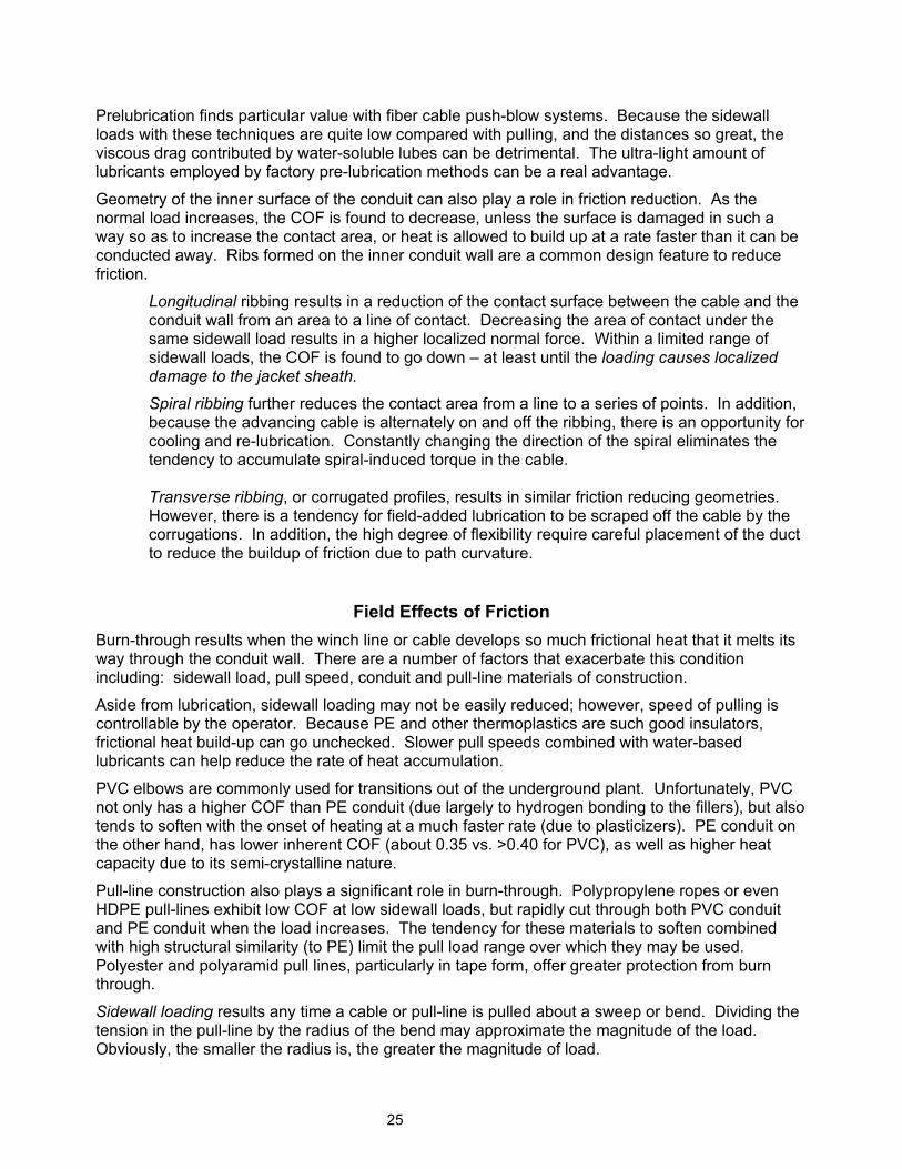
Longitudinal ribbing results in a reduction of the contact surface between the cable and the conduit wall from an area to a line of contact. Decreasing the area of contact under the same sidewall load results in a higher localized normal force. Within a limited range of sidewall loads, the COF is found to go down – at least until the loading causes localized damage to the jacket sheath.
Spiral ribbing further reduces the contact area from a line to a series of points. In addition, because the advancing cable is alternately on and off the ribbing, there is an opportunity for cooling and re-lubrication. Constantly changing the direction of the spiral eliminates the tendency to accumulate spiral-induced torque in the cable. Transverse ribbing, or corrugated profiles, results in similar friction reducing geometries. However, there is a tendency for field-added lubrication to be scraped off the cable by the corrugations. In addition, the high degree of flexibility require careful placement of the duct to reduce the buildup of friction due to path curvature.
Field Effects of Friction
Burn-through results when the winch line or cable develops so much frictional heat that it melts its way through the conduit wall. There are a number of factors that exacerbate this condition including: sidewall load, pull speed, conduit and pull-line materials of construction.
Aside from lubrication, sidewall loading may not be easily reduced; however, speed of pulling is controllable by the operator. Because PE and other thermoplastics are such good insulators, frictional heat build-up can go unchecked. Slower pull speeds combined with water-based lubricants can help reduce the rate of heat accumulation.
PVC elbows are commonly used for transitions out of the underground plant. Unfortunately, PVC not only has a higher COF than PE conduit (due largely to hydrogen bonding to the fillers), but also tends to soften with the onset of heating at a much faster rate (due to plasticizers). PE conduit on the other hand, has lower inherent COF (about 0.35 vs. >0.40 for PVC), as well as higher heat capacity due to its semi-crystalline nature.
Pull-line construction also plays a significant role in burn-through. Polypropylene ropes or even HDPE pull-lines exhibit low COF at low sidewall loads, but rapidly cut through both PVC conduit and PE conduit when the load increases. The tendency for these materials to soften combined with high structural similarity (to PE) limit the pull load range over which they may be used. Polyester and polyaramid pull lines, particularly in tape form, offer greater protection from burn through.
Sidewall loading results any time a cable or pull-line is pulled about a sweep or bend. Dividing the tension in the pull-line by the radius of the bend may approximate the magnitude of the load. Obviously, the smaller the radius is, the greater the magnitude of load.
25

Speed, as noted above, is a critical variable in the operator’s hands that can often spell the difference between success and failure. Speeds, which are too low, can result in a lot of mechanical interaction, whereas an excessively high speed results in heat build-up. Compatibility, in conjunction with high sidewall loading, can be a problem -- not only for higher relative friction, but also is a key determinant in burn-through.
Contamination with inorganic soils roughens the surfaces of both conduit and cable jacket, thus increasing the mechanical interaction between them. In addition, the embedment of small particles increases hydrogen bonding with water that may be in the conduit, further enhancing the interaction of jacket with conduit.
Placement Planning
Curvature in the conduit run is the greatest deterrent to long pulls. Some curvature is unavoidable due to path layout, i.e. elevation changes, direction changes, etc. On the other hand, sloppy installation techniques can introduce more curvature than would otherwise be planned for. For example, open trench work without proper tensioning and bedding can lead to installations that severely limit cable placement.
Equations for calculation of accumulated frictional drag have been derived and can be found in Appendix A. These are combinations of straight section and exponential sweeps. If the cable has appreciable weight, the transition to sweep up or sweep down results in significant differences. In addition, for multiple conductor power cables, certain combinations of cable multiples and free volume result in locking configurations.
Push-blow techniques are also greatly affected by friction. As noted above, pre-lubricated ducts, or very light applications of silicone emulsions, produce the best results. Techniques that rely on air predominantly to accelerate the cable work best with lightweight cables. As cable weight increases, systems with greater pushing power and piston seals provide improved performance.
Insert sizing is different for pulling vs. push-blow installations. In pulling cables, the greater the free volume in the conduit, the better, and maximum fill ratios based on cable and duct diameters are around 60 percent. On the other hand, maximum fill ratios in push-blow installations are closer to 85 percent fill. The reason for this is that if the cable is not allowed to deflect laterally, it can assume a greater axial load. The more free volume existing in the conduit during pushing, the easier it is to deflect, and having done so, the greater the curvature, and the greater the accompanying sidewall loads. Placement planning for fiber cable installation is critical because the cable lengths are so long. Typically, one would locate a point along the route possessing similar accumulated frictional drag in either direction. Part of the cable is then installed to one end of the run, then, the cable is figure-eighted to recover the opposite free end. The free end is then installed into the other end of the run. It is not uncommon to place 3,000 to 6,000 feet over any given span, and to gang placement equipment at mid-assist intervals along the path to deliver over 20,000 feet continuously in one direction. Using proper combinations of conduit design, installation method, lubrication and placing equipment, it is possible for crews to install over 40,000 feet of cable per day.
26
Section 8: Special Applications Corrugated Duct
Corrugated conduit has properties that generally make it easier to work with in difficult and confined environments. Primarily, this is a result of the lack of memory with corrugated and greater flexibility vs. smooth wall conduit. The lack of memory also provides a corrugated conduit that when installed as an innerduct (inside of another larger conduit) does not spiral and therefore has lower friction when cables are pulled through it.
The greater degree of flexibility makes corrugated conduit easier to handle when used in confined spaces and other restricted environments.
Corrugated conduit is not appropriate for use in direct buried applications because of its limited crush resistance and the difficulty of laying it in a straight path. Corrugated conduit is also not appropriate for use when cables are to be installed using air-assisted placement. Corrugated conduit is relatively thin walled and may not be able to handle the air pressure of air-assisted placement. The corrugations create air turbulence that is counter productive to the air-assisted placement systems and significantly reduce the distance cables can be blown through it.
Corrugated conduit should not be installed using directional drilling equipment due to limited tensile strength and the fact that the corrugations will create significant friction during the pull back that will likely cause the conduit to separate.
The ASTM standards that cover SIDR and SDR designs do not apply to corrugated duct. Corrugation equipment varies from producer to producer and inside and outside diameter may vary from each source of supply. All corrugated conduit specifications are per the producer only. Generally a minimum ID is specified and a maximum OD.
Corrugation design (or profile) greatly affects the properties of the conduit such as crush resistance and tensile strength. Tooling used to produce corrugated conduit does not allow the producer to change the profile or dimensions without costly retooling.
Check with the source of supply for detailed dimensional and performance specifications.
Bridge Structures
Bridge structures can range from a simple conduit placed in the bridge structure when the bridge is built to a major retrofit of an existing bridge that does not contain a conduit or structure in place to secure a single conduit or conduits. Bridge structures, new or old, require specially designed support systems to ensure structural integrity and those they meet all federal, state and local requirements.
When installing conduit on bridges, it is important to incorporate into the design the expansion and contraction of the bridge. Expansion joints must be installed in the conduit to prevent the conduit from either separating or bending and kinking due to bridge movement. As an alternative to expansion joints use of a serpentine path have been proven effective in reducing expansion/contraction issues.
Underwater
The term underwater is also referred to as marine, or submarine, applications. The three basic methods of placing a structure conduit are laying the conduit on the bottom, plowing and jetting the conduit into the sub-aqueous terrain or drilling under the waterway. Each method has it’s own unique requirements based on the type waterway, length, environmental issues, federal, state and
27
local requirements. There may be instances when all three types of application will be required on the same installation.
Conduit placed on the bottom of waterways should be black to prevent UV damage. For a complete discussion of underwater installations, see the chapter on Marine Installations in The PPI handbook of Polyethylene Pipe.
Premise (flame retardant) In addition to using conduit for installing fiber optic/communication cables in the underground there are a few other very specialized applications for conduit type products.
With the growing market for data communications systems within buildings there has been a concurrent growth in the use of fiber optic/communication cables in buildings as well. These installations typically place fiber optic/communication cables in the same cable trays and vertical risers as other communications cables and electrical cables.
Designers and installers have been concerned about identifying and protecting these fiber optic/communication cables. Manufacturers have responded with the development of several types of conduit for building use or as it is known in the industry, premise wiring.
Premise wiring generally uses plenum air spaces, vertical riser shafts and general-purpose areas to run cables throughout buildings. The types of conduit developed were specifically for these environments. Because fiber optic/communication premise wiring falls into areas generally thought of as electrical, the National Electric Code and Underwriters Laboratories have addressed the characteristics needed by conduits to be safely used in building wiring.
Initial development produced the Plenum Raceway, a specialized conduit that meets stringent Underwriters Laboratories (UL 2024) requirements for minimum flame spread and smoke generation. Plenum Raceway is a corrugated conduit made from plastic materials that do not support flame and produces almost no smoke. At this time PVDF is the material of choice for Plenum Raceway. Products for plenum air spaces are required to carry a Listing Mark to verify that the product has been tested and meets the requirements for installation in the plenum environment.
A riser raceway was developed for premise wiring applications in riser shafts. Riser Raceway meets the Underwriters Laboratories (UL 2024) requirements for vertical flame spread. Riser Raceway is also a corrugated conduit, which is currently produced from either PVC or Nylon materials. Products for riser locations are required to carry a Listing Mark to verify that the product has been tested and meets the requirements for installation in the riser environment. Plenum Raceways are permitted to be placed in a riser application.
A general-purpose raceway was developed for premise wiring applications in general purpose applications. General Purpose Raceway meets the Underwriters Laboratories (UL 2024) requirements for flame spread. General Purpose Raceway is typically a corrugated conduit, which is currently produced from either PVC or Nylon materials. Products for general-purpose locations are required to carry a Listing Mark to verify that the product has been tested and meets the requirements for installation in the riser environment. Plenum and Riser Raceways are permitted to be placed in a general-purpose application.
The uses of Plenum or Riser Raceways do not eliminate the use of a Plenum or Riser rated cable.
As the use of fiber optic/communication cables in premise wiring increases there will likely be other specific needs that may generate other types of conduit for use in building wiring systems.
28
Electrical/Building Code (conduit entry issues) Electrical/Building Code regulations vary greatly regarding the placement of conduit into a building. Codes require the use of conduit constructed of a material that is listed for use in specific building areas and these codes prohibit the use of PE conduit beyond a specific distance after entry through an exterior wall. The greatest variation in local code is the location of the transition from PE conduit to a conduit that meets the code requirement (distance from the exterior of the wall). Check your local codes for local amendments.
Armored (rodent & mechanical protection)
When placing cables in the underground there is occasionally concern about the ability of the conduit to protect the cable(s) inside. Concerns usually are for crush resistance and resistance to cutting and gnawing by animals.
This need lead to the development of armored conduit. Armored Conduit is standard PE conduit that has been wrapped with a second layer of metal and jacketed to provide a barrier to the problem of gnawing by animals. Armored Conduit also protects against cuts and abrasions from accidental strikes by persons digging nearby.
Multi-Cell Conduit
Multi-cell conduits are designed to meet special needs and unique job situations. There are a number of designs available to meet most of these special needs. Multi-cell conduit can be a product that is installed as an innerduct inside of existing conduits designed to maximize the available space in a vacant or occupied conduit or it can be a fully assembled conduit with internal conduits that when installed provides a multi channel conduit without the need to install any other innerducts. Some multi-cell designs can be direct buried like PE conduit using standard installation methods (plowing or open trenching).
Summary
The information contained in this chapter should help the reader to understand the fundamental properties of polyethylene (PE) conduit. A basic understanding of these properties will aid the engineer or designer in the use of PE conduit and serve to maximize the utility of the service into which it is ultimately installed.
While every effort has been made to present the fundamental properties as thoroughly as possible, it is obvious that this discussion is not all-inclusive. For further information concerning PE conduit the reader is referred to a variety of sources including the pipe manufacturers’ literature, additional publications of the Plastics Pipe Institute and the references at the end of this chapter.
29
References
ASTM International, F 2160, “Standard Specification for Solid Wall High Density Polyethylene (HDPE) Conduit Based on Controlled Outside Diameter (OD)
ASTM International, F 2176, “Standard Specification for Mechanical Couplings Used on Polyethylene Conduit, Duct and Innerduct.”
ASTM International, D 3350, “Standard Specification for Polyethylene Plastics Pipe and Fittings Materials” ASTM International, D 1238, “Standard Test Method for Flow Rates of Thermoplastics by Extrusion Plastometer” ASTM International, D 1693, “Standard Test Method for Environmental Stress-Cracking of Ethylene Plastics” ASTM International, F 1473, “Standard Test Method for Notch Tensile Test to Measure the Resistance to Slow Crack Growth of Polyethylene Pipes and Resins” ASTM International, D 2444, “Standard Test Method for Determination of the Impact Resistance of Thermoplastic Pipe and Fittings by Means of a Tup (Falling Weight)” ASTM International, F 1290, “ Standard Practice for Electrofusion Joining Polyolefin Pipe and Fittings” ASTM International, D 2657, “ Standard Practice for Heat Fusion Joining of Polyolefin Pipe and Fittings” ASTM International, D 2683, “Standard Specification for Socket-Type Polyethylene Fittings for Outside Diameter-Controlled Polyethylene Pipe and Tubing” ASTM International, F 1056, “Standard Specification for Socket Fusion Tools for Use in Socket Fusion Joining Polyethylene Pipe or Tubing and Fittings” National Electrical Manufacturers Association, NEMA TC 7, “Smooth-Wall Coilable Polyethylene Electrical Plastic Conduit” Underwriters Laboratories, Inc., UL 651B, “Continuous Length HDPE Conduit” Underwriters Laboratories, Inc., UL 2024, “Optical Fiber Cable Raceway” UL 651A Plastics Pipe Institute, Inc., Handbook of Polyethylene Pipe Plastics Pipe Institute, Inc., TR19, Thermoplastic Piping for the Transport of Chemicals National Electrical Code (NEC), Chapter 9 Guide for Installation of Extruded Dielectric Insulated Power Cable Systems Rated 69KV -138KV
Underground Extruded Power Cable Pulling Guide AEIC Task Group 38 IEEE Guide Distribution Cable Installation Methods in Duct Systems
30
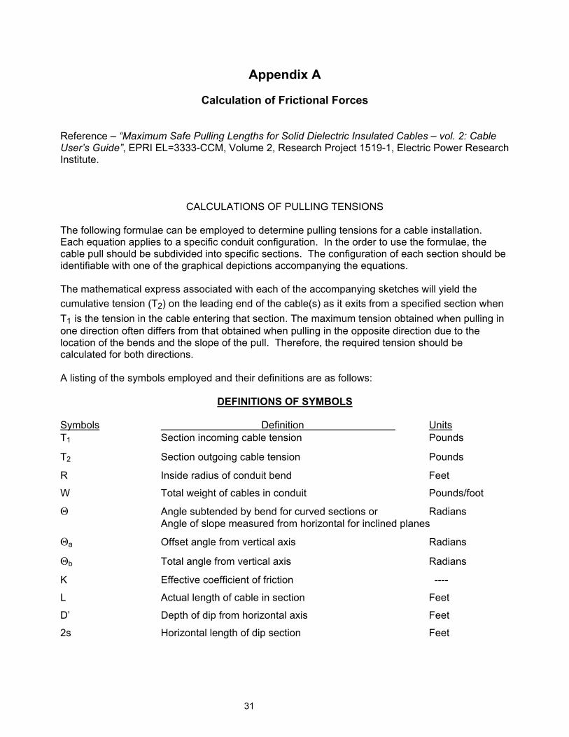
Appendix A
Calculation of Frictional Forces Reference – “Maximum Safe Pulling Lengths for Solid Dielectric Insulated Cables – vol. 2: Cable User’s Guide”, EPRI EL=3333-CCM, Volume 2, Research Project 1519-1, Electric Power Research Institute.
CALCULATIONS OF PULLING TENSIONS The following formulae can be employed to determine pulling tensions for a cable installation. Each equation applies to a specific conduit configuration. In the order to use the formulae, the cable pull should be subdivided into specific sections. The configuration of each section should be identifiable with one of the graphical depictions accompanying the equations. The mathematical express associated with each of the accompanying sketches will yield the cumulative tension (T2) on the leading end of the cable(s) as it exits from a specified section when T1 is the tension in the cable entering that section. The maximum tension obtained when pulling in one direction often differs from that obtained when pulling in the opposite direction due to the location of the bends and the slope of the pull. Therefore, the required tension should be calculated for both directions. A listing of the symbols employed and their definitions are as follows:
DEFINITIONS OF SYMBOLS Symbols Definition Units T1 Section incoming cable tension Pounds
T2 Section outgoing cable tension Pounds
R Inside radius of conduit bend Feet
W Total weight of cables in conduit Pounds/foot
Θ Angle subtended by bend for curved sections or Radians Angle of slope measured from horizontal for inclined planes
Θa Offset angle from vertical axis Radians
Θb Total angle from vertical axis Radians
K Effective coefficient of friction ----
L Actual length of cable in section Feet
D’ Depth of dip from horizontal axis Feet
2s Horizontal length of dip section Feet
31
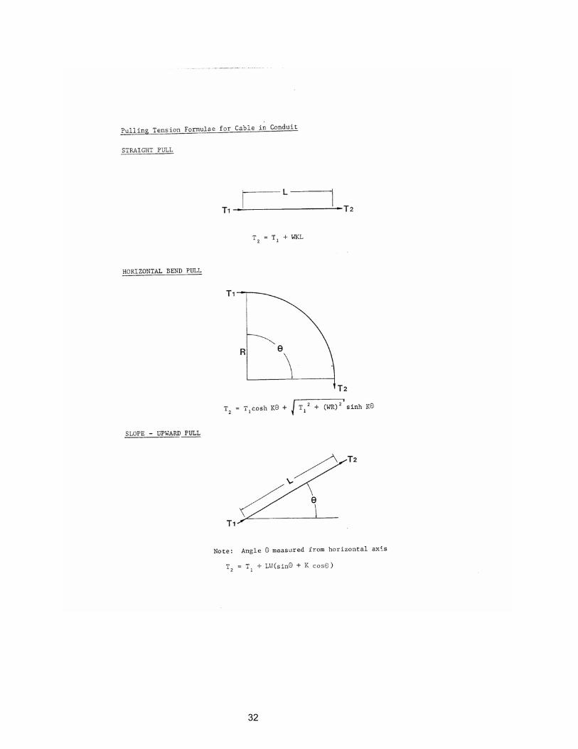
32
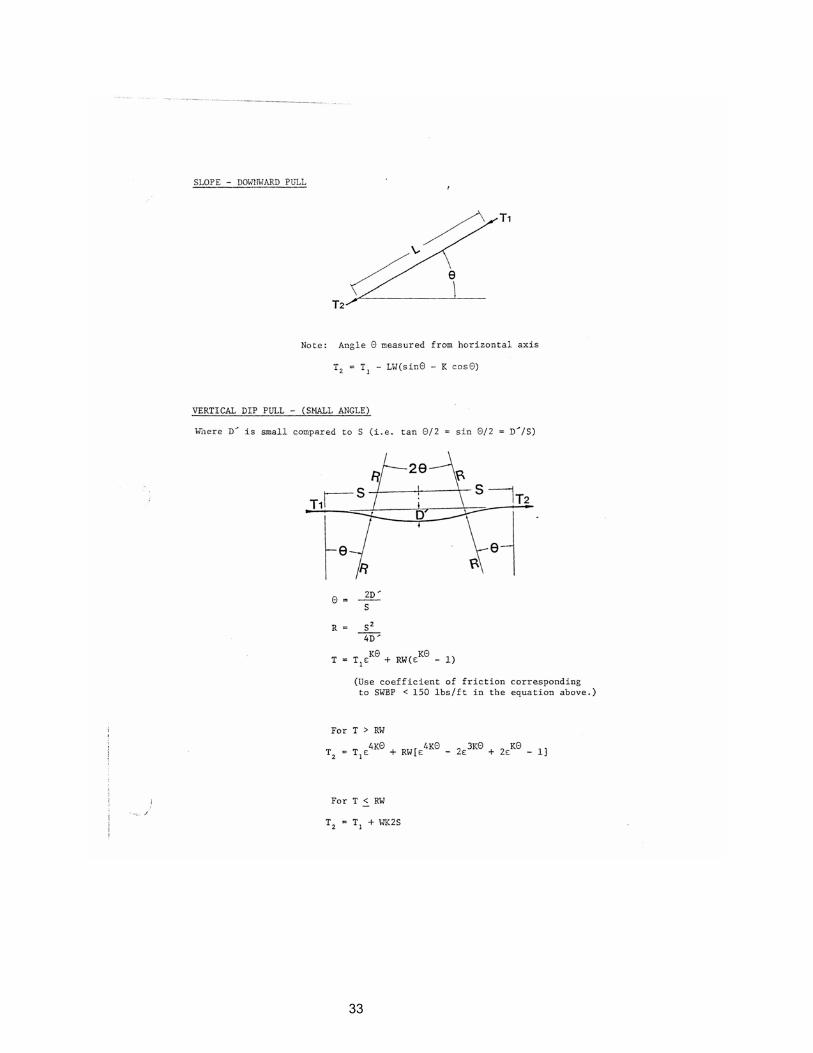
33
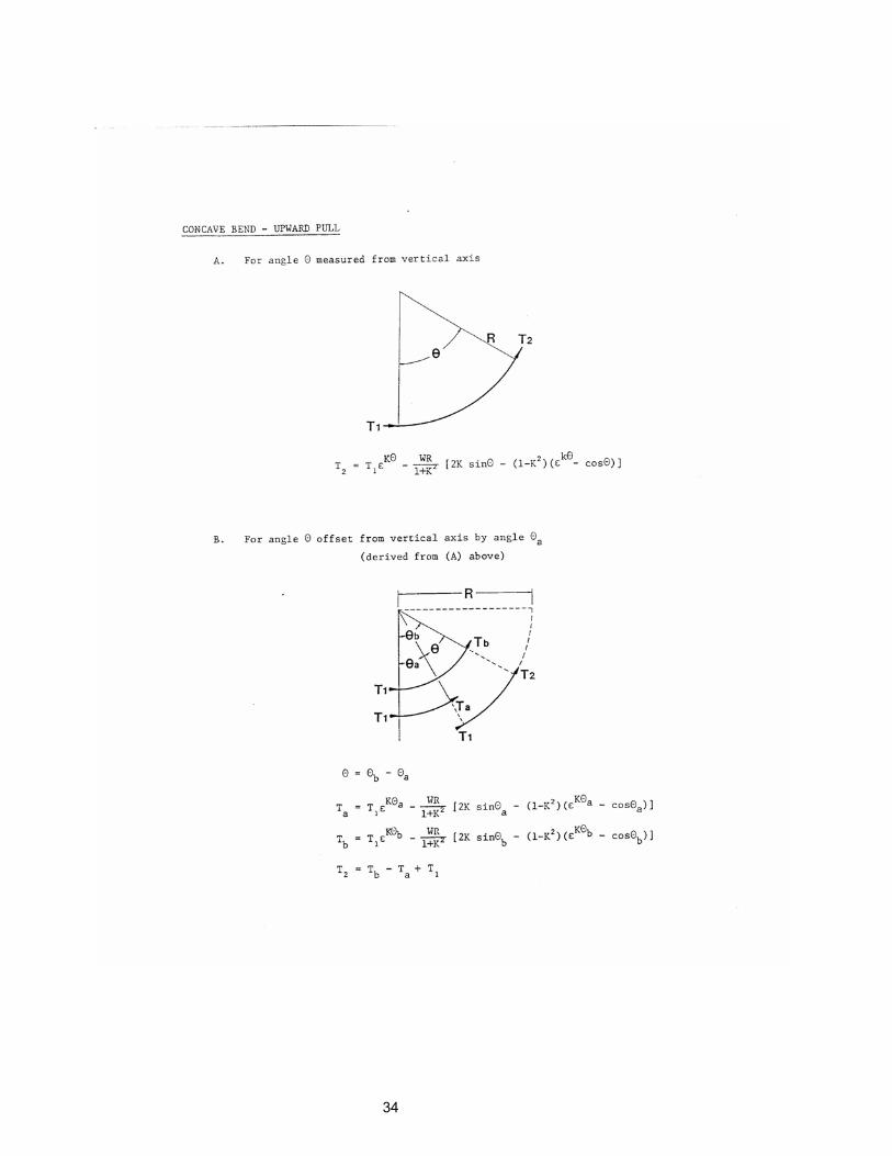
34
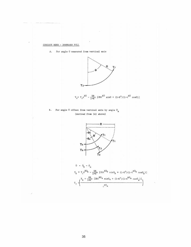
35

36
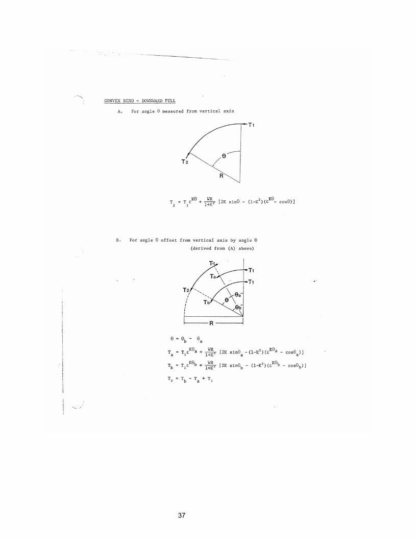
37