Embed Size (px)
Citation preview

ATL
-MU
ON
-PR
OC
-201
5-01
011
Nov
embe
r20
15
Preprint typeset in JINST style - HYPER VERSION
Trigger Algorithms and Electronics for the ATLASMuon New Small Wheel Upgrade
Liang Guana∗, on behalf of the ATLAS Muon CollaborationaUniversity of Michigan,450 Church Street, Ann Arbor, MI, 48109, U.S.A.E-mail: [email protected]
ABSTRACT: The New Small Wheel Upgrade for the ATLAS experiment will replace the innermoststation of the Muon Spectrometer in the forward region in order to maintain its current perfor-mance during high luminosity data-taking after the LHC Phase-I upgrade. The NSW, comprisingMicromegas and small Thin Gap Chambers, will reduce the rate of fake triggers coming frombackgrounds in the forward region and significantly improve the Level-1 muon trigger selectiv-ity by providing precise on-line segment measurements with ∼1 mrad angular resolution. Suchdemanding precision, together with the short time (∼ 1 µs) to prepare trigger data and perform on-line reconstruction, implies very stringent requirements on the design of trigger system and triggerelectronics. This paper presents an overview of the design of the NSW trigger system, triggeralgorithms and processor hardware.
KEYWORDS: Muon Spectrometer; Trigger algorithm; Trigger electronics; High luminosity.
∗Corresponding author.

Contents
1. Introduction 1
2. NSW upgrade and its readout scheme 2
3. NSW trigger algorithms and trigger processor 43.1 sTGC trigger scheme and trigger algorithm 53.2 MM trigger scheme and trigger algorithm 53.3 Trigger processor hardware platform 7
4. Trigger Front-end electronics 74.1 Front-end electronics for sTGC system 74.2 Front-end electronics for MM system 8
5. Conclusions 9
1. Introduction
The Large Hadron Collider (LHC) will be upgraded over the next decade in several phases towardsa High Luminosity-LHC to enhance its discovery potential [1]. The accelerator is anticipated toincrease its energy for proton-proton collisions at a center-of-mass energy of 14 TeV during thesecond run period (Run 2) started in 2015. The luminosity is expected to reach or exceed its orig-inal designed value of 1×1034 cm−2s−1 at the end of Run 2. A major upgrade to the acceleratorcomplex during the second long shutdown (LS2) starting around 2019 will double the instanta-neous luminosity from its nominal value, allowing delivery of ∼300 fb−1 data to its hosting exper-iments during the following period (Run 3). The upgrade around 2024 will yield an instantaneousluminosity of 5-7×1034 cm−2s−1. In order to take advantage of the LHC upgrades with higherdelivered statistics, the ATLAS experiment [2] will upgrade its detector on the same schedule tohandle higher event rate and integrated dose while maintaining its good detector performance.
A three-level trigger system [3] is used by the ATLAS experiment to select and record eventson-line. The Level-1 trigger [4] pre-selects candidate events at a rate of 75 kHz (100 kHz forRun 2 and Run 3) from the initial 40 MHz of collisions. Such pre-selection is done on-line within2.5 µs utilizing the Calorimeter and Muon Spectrometer customized electronics. The primaryconcern of the ATLAS Phase-I upgrade after LS2 is to improve the Level-1 trigger system for goodsingle lepton (e and µ) selectivity with existing momentum (pT) thresholds in a much higher rateenvironment compared with that in Run 1. The particular focus on the Muon Spectrometer is toimprove the rejection of fake Level-1 triggers in the forward region. As illustrated in a quadranty− z view of the ATLAS Muon Spectrometer shown in figure 1, muons traveling in the forward
– 1 –

direction are bent radially toward or away from the beam axis during their passages through End-cap toroid magnets. High pT muons are selected as tracks with small deflection angles. The Level-1muon trigger in the forward region during Run 1 relied on segment measurements at the middlemuon station (Big Wheel). Studies using the 2012 collision data showed that more than 90% of theLevel-1 triggered muons with pT > 10 GeV in the forward region could not be matched with off-linemuons. In most cases, triggers were fired by particles generated in between the innermost station(Small Wheel) and the Big Wheel from interactions of slow protons with the detector material.Requiring an associated hit at the Small Wheel for each segment measured at the Big Wheel wouldreduce faked muons by removing most of the hits not originating from the interaction point (IP).This motivated the ATLAS to utilize the present Thin Gap Chambers (TGCs) at the Small Wheelto participate Level-1 muon trigger during Run 2. Further improvements to substantially reducethe rate of fake triggered muons in the forward region and to sharpen the muon trigger turn-oncurve are expected to maintain detector performance in Run 3 and beyond. This will be achievedby replacing the present Muon Small Wheels with a New Small Wheel (NSW) [5] in a Phase-I upgrade. Improved segment resolution of the Big Wheel trigger as proposed in Phase-II willprovide two sets of independent segment measurements for enhanced pT resolution.
The NSW upgrade will improve the Level-1 muon trigger in the forward region as well asmaintain excellent muon tracking in high rate environment. In this paper, we focus on discussingthe NSW muon trigger capabilities leaving its tracking performance to be discussed elsewhere [5,6, 7]. Organization of the paper is as following. Section 2 presents an overview of the NSWupgrade project, requirements for Level-1 triggering and the general NSW trigger scheme. Section3 introduces trigger algorithms for reconstructing candidate muon track segments at the NSW andthe hardware platform for implementing these algorithms. Section 4 discusses the development oftrigger Front-end electronics for two sub-detector systems.
2. NSW upgrade and its readout scheme
The NSW upgrade introduces two types of high-rate capable large-area gaseous detectors, thesmall-strip Thin Gap Chamber (sTGC) [8, 9] and the Micro-Mesh Gaseous detector (MM) [10,11], for precise reconstruction of muon segments both on-line and off-line in an environment withhit rates of up to ∼15 kHz/cm2 (hottest region with maximum luminosity of 7×1034 cm−2s−1
after Phase-II upgrade). These detectors are arranged in 16 trapezoidal shaped sectors per endwith each sector comprised of eight layers of MM sandwiched between two sTGC quadruplets.Both detector technologies provide trigger and tracking capability as both can discriminate the25 ns bunch crossings as well as determine track hit positions with an accuracy of ∼100 µm perdetector plane in the bending direction. sTGCs utilize 3.2-mm-pitch readout strips and ∼ 8 cmwide segmented pads on opposite sides of cathode planes. Anode wires perpendicular to strips arealso read out for non-bending coordinate measurements. MMs have ∼0.4-mm fine pitch readoutstrips for each detector plane. MM strips are configured with 4 layers in azimuthal direction and4 layers inclined at small angles with respect to azimuthal strips. In total, these detectors cover anarea of approximately 2000 m2 and have about 2.5 million readout channels.
The main requirement for NSW trigger at Level-1 is to reconstruct on-line segments with anaccuracy of ∼1 mrad in the range of 1.3 < |η | < 2.4 for corroboration with the Big Wheel segments
– 2 –
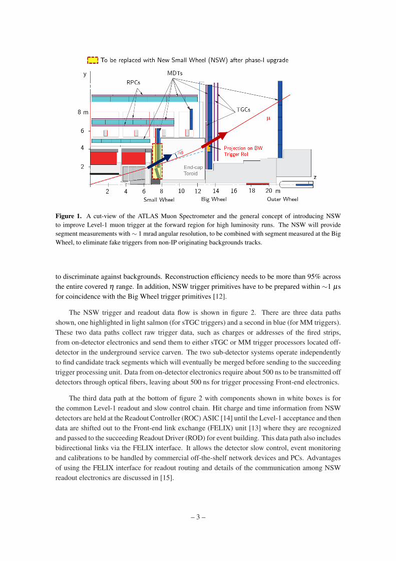
Figure 1. A cut-view of the ATLAS Muon Spectrometer and the general concept of introducing NSWto improve Level-1 muon trigger at the forward region for high luminosity runs. The NSW will providesegment measurements with ∼ 1 mrad angular resolution, to be combined with segment measured at the BigWheel, to eliminate fake triggers from non-IP originating backgrounds tracks.
to discriminate against backgrounds. Reconstruction efficiency needs to be more than 95% acrossthe entire covered η range. In addition, NSW trigger primitives have to be prepared within ∼1 µsfor coincidence with the Big Wheel trigger primitives [12].
The NSW trigger and readout data flow is shown in figure 2. There are three data pathsshown, one highlighted in light salmon (for sTGC triggers) and a second in blue (for MM triggers).These two data paths collect raw trigger data, such as charges or addresses of the fired strips,from on-detector electronics and send them to either sTGC or MM trigger processors located off-detector in the underground service carven. The two sub-detector systems operate independentlyto find candidate track segments which will eventually be merged before sending to the succeedingtrigger processing unit. Data from on-detector electronics require about 500 ns to be transmitted offdetectors through optical fibers, leaving about 500 ns for trigger processing Front-end electronics.
The third data path at the bottom of figure 2 with components shown in white boxes is forthe common Level-1 readout and slow control chain. Hit charge and time information from NSWdetectors are held at the Readout Controller (ROC) ASIC [14] until the Level-1 acceptance and thendata are shifted out to the Front-end link exchange (FELIX) unit [13] where they are recognizedand passed to the succeeding Readout Driver (ROD) for event building. This data path also includesbidirectional links via the FELIX interface. It allows the detector slow control, event monitoringand calibrations to be handled by commercial off-the-shelf network devices and PCs. Advantagesof using the FELIX interface for readout routing and details of the communication among NSWreadout electronics are discussed in [15].
– 3 –

Figure 2. NSW trigger and readout electronics and data flow. Top two data paths with components high-lighted in light salmon and blue are for sTGC and MM triggers, respectively. The data path at the bottom iscommon for sTGC and MM for Level-1 readout and slow control.
Table 1. Proposed NSW track segment data format
Data Field sTGC hit MM hit ∆θ (mrad) R-index φ -index spareNumber of Bits 2 2 5 8 6 1
3. NSW trigger algorithms and trigger processor
Each track segment reconstructed by NSW trigger processors will be presented as 24-bit data withthe format shown in table 1. Two bits will be used to indicate the segment quality for each sub-detector system (sTGC or MM), i.e. whether it is also found by the other sub-detector system.Five bits will be used to transmit the ∆θ which is the angular deviation of the NSW segment withrespect to an infinite momentum track from the IP to the segment’s radial position in the NSW.The resolution for ∆θ is 1 mrad. Eight bits R-index and six bits φ -index will represent the radialand azimuthal projections of the NSW segment on the Big Wheel trigger RoI. The correspondinggranularity is 0.005 × 20 mrad in η × φ .
Up to 8 track segments (4 per sTGC or MM) will be reconstructed for each NSW sector perbunch crossing. They will be sent through two optical fiber links running at 6.4 Gbps to new SectorLogic (SL) Boards for trigger matching with segments found by the Big Wheel. Due to substantialdifferences in detector characteristics, geometry and electronics, sTGC and MM employ differenttrigger processors with specifically tailored trigger algorithms for segment reconstruction.
– 4 –

3.1 sTGC trigger scheme and trigger algorithm
The structure of a single sTGC detector plane is shown in figure 3 (a). As illustrated in figure 2,each sTGC strip or pad will be connected to one channel of a VMM [16], a 64-channel Amplifier-Shape-Discriminator ASIC. Timing pulses of fired pads output from the VMM will be sent to thepad Trigger Data Serializer ASIC (pad-TDS) [17]. Pad-TDS ASICs in all TGC planes will thentransmit the binary pad firing information, together with the bunch crossing number (BCID), to thePad Trigger Logic Board where three out of four coincidences are made per quadruplet to formpad-trigger roads. As shown in figure 3 (b), sTGC pads from different detector layers are staggeredby 1/2 pad width in the η direction. A pre-selected pad-trigger road therefore covers only about13 strips per detector plane. Upon the formation of a pad-trigger road, its radial and azimuthalinformation are sent to the strip Trigger Data Serializer (strip-TDS). The strip-TDS stores chargedata from VMMs connected to sTGC strips and performs the pad-strip data matching. Resultingoutput from a strip-TDS are charge data from those strips in a strip band selected by the pad-trigger road. Charge data together with strip band ID and pad-trigger road φ -ID are passed fromthe strip-TDS to the sTGC data packet Router [18] where it aggregates inputs from all strip-TDSsof a detector plane in a sector and transmits data to the sTGC trigger processor via optical fibers.The trigger scheme where “pad pre-trigger roads" select small number of strips to transmit data,drastically reduces the bandwidth needed to move strip data off detector.
The basic principle of sTGC trigger algorithm can be viewed in the illustration of figure 3 (c).Strip charge data are first routed to their corresponding layer centroid finder. Charge thresholdsare applied to select only up to five strips within a strip band for the layer centroid calculation.Such implementation takes into the consideration that real muons usually leave hit clusters with 3-5 strips. A layer centroid in the local reference frame is calculated using Digital Signal Processing(DSP) blocks as (∑N
i=1 SiQi)/(∑Ni=1 Qi), where Si and Qi are the strip number and the strip charge,
respectively. The layer centroid in the global NSW reference frame is then determined by addingthe local centroid with its global offset in the radial direction. This offset is converted from the stripband ID and the cluster position within the strip band using look-up-tables (LUTs). Quadrupletcentroids are calculated in the next step as averages of their corresponding layer centroids. Poorlayer centroids can arise from delta-ray or neutron hits with large (> 5 strips) clusters or noisehits with extra narrow (single strip) clusters. The algorithm is adjustable to exclude those poorlayer centroids from averaging and prevent them from spoiling the quadruplet hit position. Forcalculating ∆θ of the segment, a LUT is present to provide each centroid of the pivot quadruplet(the quadruplet close to the IP) with a range of acceptable centroids in the confirmation quadruplet.Centroids from the confirmation quadruplet are converted into ∆θ with those found out of range(|∆θ |>15 mrad) being rejected as non-pointing segments. Similarly, the R-index for the segment isdetermined by another set of LUTs based on the pivot quadruplet centroid and the segment pointing.The φ -index is determined from the pad-trigger road φ -ID input from the trigger processor.
3.2 MM trigger scheme and trigger algorithm
The layout of a single MM detector plane is depicted in figure 4 (a). Unlike sTGC, the ∼0.4-mm-pitch offered by a MM strip plane determines the hit position from a single strip with sub-mmresolution without the need to calculate the hit centroid. Strips in a MM quadruplet are arranged as
– 5 –

Figure 3. sTGC detector structure (a), readout strips and pads arrangement in a quadruplet (b) and illustra-tion of segment reconstruction with eight sTGC strip planes (c).
shown in figure 4 (b) so that two horizontal strip planes are parallel to the base of the NSW sectortrapezoid whereas strips from the other two planes have small angles (1.5 ◦) with respect to thosehorizontal strips. For MM trigger, the VMM ASIC connected to strips makes use of a mode called"Address in Real Time (ART)". In this mode, the address of the first threshold-crossing strip in anevent is encoded in the VMM. An ART ASIC then collects these strip address data from 32 VMMsand choses up to 8 hits to be shifted out. Eventually, an ART Data Driver Card (ADDC), hostingtwo ART ASICs per card, transmits first hit strip addresses using optical fibers to the MM triggerprocessor of a specific NSW sector.
The basic principle of the MM trigger algorithm for segment reconstruction can be explainedwith figure 4 (c). Hit strip addresses from a certain detector plane are first translated into slopesof infinite momentum tracks from the IP to those hit positions using LUTs. The entire η rangecovered by the NSW is divided into a number (N) of slope roads. Each slope road represents arange of acceptable slopes for straight tracks coming from IP to that subdivided η range. Slopesconverted from strip addresses are then stored in a ring buffer with N(slope roads) × 8(strip planes)× T (bunch crossings). The buffer is checked every bunch crossing and a segment candidate isdefined as a multiple layer coincidence within a slope road. The algorithm enables the triggerto be resilient to backgrounds originating far from the IP. Once a segment candidate is found,slopes from individual planes are sent to “slope fitter" logic where the so called global slopes andlocal slopes are calculated. The global slope is a slope derived from the mean position of all hitsin a strip plane category (horizontal or stereo) and the location of the IP. The local slope, onlycalculated for horizontal planes, is the least square fit of all hits in horizontal planes to a single line.It represents the segment pointing within the NSW and is independent of the IP location. Finally,taking geometric relationship among MM detectors, IP, and Big Wheel RoIs into consideration,∆θ and the projection on Big Wheel RoI are calculated using global and local slopes. Calculationsand fitting solutions are pre-stored in LUTs and pre-loaded into processing FPGAs for fast segmentreconstruction.
– 6 –
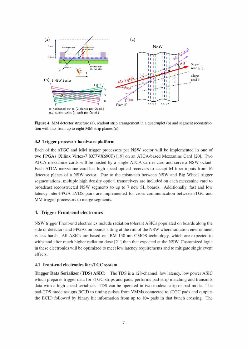
Figure 4. MM detector structure (a), readout strip arrangement in a quadruplet (b) and segment reconstruc-tion with hits from up to eight MM strip planes (c).
3.3 Trigger processor hardware platform
Each of the sTGC and MM trigger processors per NSW sector will be implemented in one oftwo FPGAs (Xilinx Virtex-7 XC7VX690T) [19] on an ATCA-based Mezzanine Card [20]. TwoATCA mezzanine cards will be hosted by a single ATCA carrier card and serve a NSW octant.Each ATCA mezzanine card has high speed optical receivers to accept 64 fiber inputs from 16detector planes of a NSW sector. Due to the mismatch between NSW and Big Wheel triggersegmentations, multiple high density optical transceivers are included on each mezzanine card tobroadcast reconstructed NSW segments to up to 7 new SL boards. Additionally, fast and lowlatency inter-FPGA LVDS pairs are implemented for cross communication between sTGC andMM trigger processors to merge segments.
4. Trigger Front-end electronics
NSW trigger Front-end electronics include radiation tolerant ASICs populated on boards along theside of detectors and FPGAs on boards sitting at the rim of the NSW where radiation environmentis less harsh. All ASICs are based on IBM 130 nm CMOS technology, which are expected towithstand after much higher radiation dose [21] than that expected at the NSW. Customized logicin these electronics will be optimized to meet low latency requirements and to mitigate single eventeffects.
4.1 Front-end electronics for sTGC system
Trigger Data Serializer (TDS) ASIC: The TDS is a 128-channel, low latency, low power ASICwhich prepares trigger data for sTGC strips and pads, performs pad-strip matching and transmitsdata with a high speed serializer. TDS can be operated in two modes: strip or pad mode. Thepad-TDS mode assigns BCID to timing pulses from VMMs connected to sTGC pads and outputsthe BCID followed by binary hit information from up to 104 pads in that bunch crossing. The
– 7 –
pad-TDS provides programmable delay for each pad input with a 3.125 ns step to compensatesignal arrival time difference due to the variable pad location within a detector plane. The strip-TDS mode decodes 6-bit hit charge data from strips, assigns each hit a BCID and stores them ina ring buffer. Upon receiving a pad-trigger road, the strip-TDS searches for hits both within thepre-trigger selected strip band using a LUT and with a BCID matching the trigger road. Chargedata from up to 14 matched strips, appended with BCID, strip band ID and trigger road φ -ID, areframed, scrambled and sent out via the TDS serializer. The serializer operates at 4.8 Gbps, sending120 bits per bunch crossing in both strip and pad modes for fixed latency triggers. A photo of thefirst TDS prototype packaged with a 400 pin BGA is shown in figure 5 (a). Core logic of the TDShas been verified with the first prototype. The measured eye diagram for the serializer is shown atthe bottom of figure 5 (a), demonstrating its good performance.
Pad Trigger Logic Board: The Pad Trigger Logic board is based on a Xilinx Kintex-7 FPGAand will be located on the NSW rim to collect hit data from the pad-TDSs in 8 sTGC planes withina NSW sector. The four layers of pad hits in a quadruplet will be examined for three out of fourcoincidences each bunch crossing. A further coincidence between the two quadruplets will forma pad-trigger road. Up to three pad-trigger roads per sector will be sent to strip-TDSs per bunchcrossing as simulation suggests the probability to have more than three muons is less than 0.3%.Trigger road information with 12 bit BCID, 8 bit Band-ID and 5 bit φ -ID will be sent over twodifferential pairs together with a 160 MHz differential clock and a single ended frame line whichindicates valid trigger data.
sTGC Router Board: The router board will also sit on the NSW rim. Each board deals witha single sTGC plane in the NSW sector. The board will accept up to 10 strip-TDS inputs from adetector plane and send up to four active inputs per bunch crossing through its optical transceivers.Commercial repeater chips will be used at the receiving end of the Router to recondition the highspeed signals to suppress transmission errors. Data transmitted from the strip-TDSs are packagedinto 30-bit packets with unique headers for self identification as data or Null packets. To minimizelatency, logic implemented in Router board FPGA will recognize an active input before receivingits entire data frame and set-up routing for it. A picture of the first developed prototype is shown infigure 5 (b) and test results can be found in [18].
4.2 Front-end electronics for MM system
Address in Real Time (ART) ASIC: The ART ASIC acts as a MM trigger data concentratorwhich accepts inputs from 32 VMMs and selects up to 8 active channel inputs to transmit perbunch crossing. An active input from a 64-channel VMM to an ART ASIC consists of a flagsignal followed by first above-threshold strip address encoded in six bits. Input signals to the ARTASIC will be skewed with programmable delays for correct sampling. The ART ASIC will start theprocessing by looking for the presence of ART flags from all VMMs inputs in each bunch crossing.A valid flag from any VMM will register a hit in the hit list. First 8 hits with non-zero flags will beselected from the hit list using a cascaded priority selector circuit. Strip addresses are deserializedafter ART flags are detected. Finally a data formatter circuit will organize the data to be sent tothe GBTx ASIC [22]. Including eight 6-bit strip addresses, eight 5-bit VMM IDs and a BCID,
– 8 –

Figure 5. The first prototype of the Trigger Data Serializer ASIC in a 400 pin BGA package and a measuredeye diagram for its serializer running at 4.8 Gbps (a), the first sTGC Router prototype board (b).
there will be 112 bits transmitted per bunch crossing from the ART ASIC to the GBTx using 14differential pairs running at 320 Mbps Double Data Rate (DDR) mode.
ART Data Driver Card (ADDC): Each ADDC hosts two ART ASICs, two GBTx ASICs andthe VTTx which is a radiation tolerant dual-channel transmitter [23]. Each GBTx links with anART ASIC transmits data through a serial link at 4.8 Gbps (4.48 Gbps bandwidth for data). TheVTTx converts two electrical-links into optical signals and sends MM trigger data to a MM trig-ger processor. Each MM detector plane has four ADDCs and and 32 cards per NSW sector areconnected to a MM trigger processor.
5. Conclusions
The ATLAS Muon NSW upgrade will replace the innermost muon station in the forward regionwith high-rate capable precision trigger and tracking detectors to improve Level-1 muon triggerin the End-cap region as well as to maintain excellent muon tracking capability in the high rateenvironment foreseen for LHC high luminosity runs after the Phase-I upgrade. The participationof NSW in the Level-1 muon trigger by providing segment measurements with 1 mrad angularresolution will be powerful to discriminate muons against backgrounds with high track density.Good angular resolution at NSW will also substantially improve pT resolution of the muon triggerafter a similar resolution improvement to the Big Wheel segment measurement is implemented inPhase-II upgrade.
A complex NSW trigger and readout electronics system is under intensive development. Re-quirement of NSW segments be reconstructed with ∼1 mrad accuracy within about 1 µs imposesgreat challenges on the design of the NSW trigger electronics. First prototypes of NSW triggerASICs and Front-end boards are being developed and tested. Separate trigger algorithms for thetwo NSW sub-detector systems (sTGC and MM) have been developed. These two independentsub-systems provide redundancy in the high track density environment of the future LHC. Trig-ger algorithms will be implemented in FPGAs on ATCA-based mezzanine cards with high densityoptical links and interconnections. A vertical slice is presently under preparation to integrate andexercise all trigger electronics and trigger algorithms before the final NSW commissioning.
– 9 –

References
[1] L. Rossi, LHC upgrade plans: options and strategy, No. CERN-ATS-2011-257, (2011).
[2] ATLAS Collaboration, The ATLAS experiment at the CERN Large Hadron Collider, 2008 JINST 3.08S08003.
[3] R. Hauser, The ATLAS trigger system, Eur. Phy. J. C, 34, s01, s173-s183 (2004)
[4] W. Buttinger, The ATLAS Level-1 trigger system, Journal of Physics: Conference Series, 396, ( 2012)
[5] ATLAS Collaboration, New small wheel Technical Design Report, No. CERN-LHCC-2013-006, (2013)
[6] G. Iakovidis, The Micromegas project for the ATLAS upgrade, 2013 JINST 8.12 C12007
[7] Y. Benhammou, Precision tracking with small-strip Thin Gap Chamber (sTGC): from Test Beam toATLAS NSW Upgrade, Proceedings of EPS-HEP, Stockholm, Sweden, (2013)
[8] V. Smakhtin, et al., Thin Gap Chamber upgrade for SLHC: Position resolution in a test beam, Nucl.Instr. and Meth. A 598.1, (2009)
[9] J. Chapman, et al., Simulation Studies of Characteristics and Performance of small-strip Thin GapChamber for the ATLAS New Small Wheel Upgrade, ATL-MUON-PUB-2014-001, (2014)
[10] T. Alexopoulos, et al., A spark-resistant bulk-micromegas chamber for high-rate applications, Nucl.Instr. and Meth. A 640.1, (2011)
[11] J. Wotschack, The development of large-area micromegas detectors for the ATLAS upgrade, ModernPhys. Lett. A 28.13, (2013)
[12] ATLAS Collaboration, Technical Design Report for the Phase-I Upgrade of the ATLAS TDAQ System,No. CERN-LHCC-2013-018, (2013)
[13] S. Ryu, FELIX: the detector readout upgrade of the ATLAS experiment, ATL-DAQ-SLIDE-2015-558,(2015)
[14] R. Coliban, The Read Out Controller for the ATLAS New Small Wheel, TWEPP, Lisbon, Portugal,(2015)
[15] Y. Munwes, Upgrade of the first level muon trigger in the end-cap new small wheel region of theATLAS detector, ANIMMA, Marseille, France (2013)
[16] G. De Geronimo, Upgrade of the first level muon trigger in the end-cap new small wheel region of theATLAS detector, IEEE NSS/MIC, Anaheim, USA (2012)
[17] J. Wang, et al., Characterization of a Serializer ASIC chip for the upgrade of the ATLAS muondetector, arXiv:1509.06636, (2015)
[18] J. Wang, et al., FPGA Implementation of a Fixed Latency Scheme in a Signal Packet Router for theUpgrade of ATLAS Forward Muon Trigger Electronics, IEEE Trans. Nucl. Sci., 62.5, (2015)
[19] Xilinx FPGA. http://www.xilinx.com/
[20] S. Martoiu, Trigger Processor Hardware, private communication
[21] L. Gonella, et al., Total Ionizing Dose effects in 130-nm commercial CMOS technologies for HEPexperiments, Nucl. Instr. and Meth. A 582.13, (2007)
[22] P. Moreira, et al., The GBT project, TWEPP, Paris, France, (2009)
[23] J. Troska, et al., Versatile transceiver and transmitter production status, 2013 JINST 8.12 C12030
– 10 –