Embed Size (px)
Citation preview
TRG Review of Preliminary Engineering Phase I
DEEP GEOLOGICAL REPOSITORY PROJECT
Original signed by
Morris Medd
Original signed by
Wolf Seidler
Original signed by
Peter Tiley
Date: 2 October, 2009
Submitted To: Ian Pritchard, NWMO
Original signed by
Bill Smyth .
Original signed by
Evert Hoek
Page 1
TRG Review of Preliminary Engineering Phase I
TABLE OF CONTENTS
SUMMARY ................................................................................................................................................................ 3 T-H-E HANDLING ....................................................................................................................................................... 5 REPOSITORY VENTILATION ............. ........... ........................... ..... ..................................... .......................................... 7 SHAFT LINING ........................................................................................................................................................... 9 SHAFT EXCAVATION and LINING ............................................................................................................................. 10 UNDERGROUND EXCAVATIONS .............................................................................................................................. 11 FIRE ......................................................................................................................................................................... 13 MAIN CAGE and HOIST ........................................................................................................................................... 14 MAIN CAGE ROPE CHANGING ........................................................ : ....................................................................... 15 MAIN SHAFT AUXILIARY CAGE HOIST ..................................................................................................................... 16 VENTILATION SHAFT HOIST .................................................................................................................................... 17 VENTILATION SHAFT LOADING STATION ......................... ........................................................................................ 17 ROAD HEADERS ................ .................................................................................................. ..................................... 18
Application to Shaft Work ................................................................................................................................. 18 Application to Development .............................................................................................................................. 19
INTEGRATING A SINKING CONTRACTOR INTO THE DESIGN TEAM ......................................................................... 20 VARIOUS ................................................................................................................................................................. 21 APPENDIX - COMMENTS ON ROADHEADER EXCAVATION .................................................................. 23
Page 2
TRG Review of Preliminary Engineering Phase I
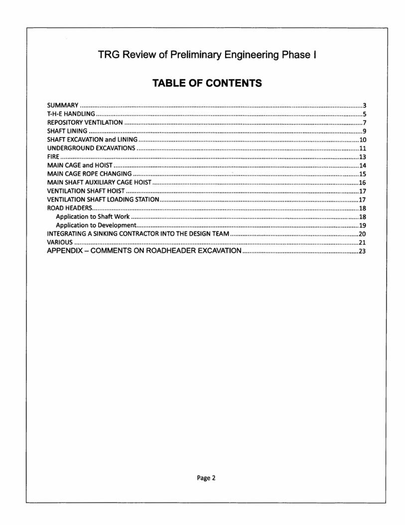
SUMMARY
1. The Technical Review Group (TRG) met with Hatch Limited (Hatch) during the week of 27 September 2009 to review the information Hatch and NWMO have provided us for the DGR Project.
2. The purpose of the review was to determine if there were any possibilities for fatal flaws in these designs as well as provide comments and recommendations to NWMO on various aspects of the project.
3. We have concluded that there are no fatal flaws in the proposed design. We do, however, have concerns about the provision for handling and storing the T-H-E (TIle Hole Equivalent) packages. We believe that if these units, as well as any other "Non-Fork Liftable" packages, can be reduced in size or repackaged, on surface, to permit them to be transported to the underground storage areas and placed there with fork lifts numerous simplifications to handling and storing these packages will result. Reduction in the height of the maximum package to 4.6m will lead to overall reduction in height of the cage, headframe and DGR level brow.
4. It is not clear why the main cage footprint is S.2m. The largest item we have data on is a part of the heat exchanger which is 3.6m wide. If the cage width could be reduced to 4m the shaft could be reduced to Sm.
S. We believe that the vent shaft is too small in diameter to be sunk efficiently. It should be increased to Sm.
6. The shafts should be sunk by conventional drill and blast methods because road headers have yet to been proven in hard ground for shafts of the sizes being contemplated.
7. Although road headers are an acceptable option for lateral development we recommend testing one in an exposed Coburg formation before approving this approach. Notwithstanding the possibility of using road headers for development, we believe that properly controlled blasting can produce an equal quality of rock face and an EDZ almost comparable to a road header.
8. The loading pocket design in the ventilation shaft should be altered so that its discharge path is vertically down and use a pan feeder to load the measuring flask.
9. A production rate of 1S0 tonnes per hour can be achieved using a pair of 8.0 tonne capacity skips in balance when operating at a maximum speed of 10 m/s. This will produce about 3000 tonnes per day (assuming -12 hours available for hoisting) to match the anticipated requirement of excavating approximately 2MT of lateral development in 2 years.
Page 3
TRG Review of Preliminary Engineering Phase I
10. From the information and analyses that were made available for review it appears that the Cobourg formation is tectonically undisturbed, very uniform, its strength is high in relation to the in situ stress field, it appears to have relatively few adverse structural features and its permeability is very low. These characteristics make it a favourable host rock for the construction of a stable waste repository. Further testing and analyses are required to confirm these observations but the TRG is optimistic that these conclusions will be shown to be valid.
11. The preliminary design of the emplacement rooms has been reviewed and found to be generally satisfactory. However, suggested changes in the ventilation system and in the placement procedures for large waste packages would result in rooms of lower height and hence the design will need to be re-considered.
12. The decision to design a dead end ventilation system has resulted in a design which requires extensive ductwork. The system will be complex to install and maintain and will introduce unnecessary extra steel to the project. We recommend re-designing the system to be a flow through with minimal ductwork. We believe that this approach will also reduce the total amount of excavation required for the repository. We have provided a sketch of a possible arrangement.
13. The original main cage hoist is satisfactory for the duties which will be required. The rope safety factors, tread pressures and T1 fT2 ratios are well within normal practice. The head ropes should be a low rotation, stranded design such as Trefileuropes Notorplast.
14. At present there is no provision for changing head or balance ropes on the main cage hoist. We recommend using a multi-rope, rope changing system. This equipment would allow all ropes to be changed from the surface. This represents a significant increase in safety for these procedures.
15. The Mary Ann ( auxiliary service ) hoist in the main shaft should be a two rope Koepe supporting a cage and counterweight. This option will eliminate the need for wooden guides and dogging systems.
16. The main cage should be equipped with dogs designed to operate on steel guides. This option will eliminate any arguments that the cage might fall if the headropes failed.
17. We see no necessity for using reinforcing steel in the shaft liner concrete. We believe that this exposes the concrete to the risk of spalling because the rebar will corrode. We also recommend replacing the ground control shotcrete with a poured concrete inner liner.
18. We did not receive any information on the work carried out to define fire hazards and how to respond to them. These studies will be required before the design can be finalized.
19. Proper HAZOPS analysis will have to be carried out on the various sections of the facility.
20. We would like to see an overall system schedule prior to the next meeting with Hatch.
Page 4
TRG Review of Preliminary Engineering Phase I
T-H-E HANDLING After reading the material provided before hand and with the benefit of two days of comprehensive
presentations by various members of the design team the TRG has identified only one issue that could
be a potential fatal flaw - the handling of the "T-H-E PACKAGES". Fortunately the NWMO had already
independently identified this matter as needing some redesign and apparently steps are already
underway in that re.gard.
The TRG believe that one solution that should be given serious consideration is to arrange for the
cutting or repackaging of the T-H-E tubes into lengths that can be placed inside a concrete (or steel)
canister probably similar in size to the canisters used to emplace the resin liners. A hot cell or shielded
work area will need to be installed. We recognize that this would involve considerable expense to put
in but a revised approach whereby all waste can be put into canisters that are no larger than the resin
liner containers could result in many off setting savings on top of providing a safer and more robust
emplacement scheme for T-H-E packages. If a decision is made to reduce the size of the T-H-E
packages then other large pieces such as the heat exchangers should also be reduced in size to
make them transportable by forklift either in a canister or on a pallet. This would add more uniformity
to the equipment and to the emplacement procedures. On this basis some examples of potential
savings and/or other advantages include:
• Don't need steel overpacks for T-H-E packages because several shorter pieces can be put in
concrete overpacks (will reduce cost and long term hydrogen gas production)
• Head frame and shaft length could potentially be shorter
• The repository station would not have to be so high
• The self propelled rail cart can be shorter
• The diameter of the main waste shaft could potentially be reduced
Page 5
TRG Review of Preliminary Engineering Phase I
• The track would not have to be extended beyond the end of the repository level shaft station as
forklifts could handle all waste from the station to the emplacement rooms (assumes that all
non-forkliftable LLW would also be reduced to a size that can be put on a pallet and placed via
a forklift
• The sequencing of room filling would have more flexibility i.e. don't have to put large pieces in
NW rooms first
• The use of gantry's in the rooms could potentially be eliminated
• The height of some rooms can consequently be reduced or have a higher fill factor
• There would be less steel in the repository for producing hydrogen gas
• The 14m turning radius restriction could be reduced
Alternately if this approach is absolutely not possible consider designing and fabricating prototype
versions of the related equipment so that safe handling can be demonstrated to NWMO in advance of
any public hearings.
Recommendation: Abandon the current transport and emplacement scheme for T-H-E packages in
favour of cutting the pipes into more manageable lengths and repackaging the cut pieces and/or their
contents in concrete.
Page 6
TRG Review of Preliminary Engineering Phase I
REPOSITORY VENTILATION The ventilation system currently proposed by Hatch embodies the following salient features:
• The system is a pull system; the total mine airflow is pulled down the intake shaft and up the
ventilation shaft utilizing a primary fan located on surface.
• Return air from each room is conveyed from the end of the room back to the ventilation shaft
via permanently installed steel ventilation ducting fitted with an exhaust fan.
• Airflow volume through filled rooms is to be three to four air exchanges per hour.
The TRG suggests an approach (which is shown below) as follows:
• The surface fan exhausting the total mine airflow would be eliminated. The flow from shaft
entry to exit would be powered by return air fan(s), located near the base of the ventilation
shaft. The fans would be equipped with silencers to keep ambient noise within acceptable
levels.
• Flow-through ventilation would be employed to ventilate filled rooms. Rooms would be
connected to a return air drift which would convey the total room airflow to the base of the
ventilation shaft.
Attributes of the suggested approach are:
• The surface exhaust fan is eliminated thereby eliminating surface noise, reducing collar
construction requirements and lowering capital cost.
• All room and access drift heights would be excavated with a lower back height. The overall
underground excavation volume will be significantly reduced, even considering the additional
requirement of the return air drift.
• The requirement for the placement and maintenance of permanent steel ducting is drastically
reduced, positively impacting capital cost and lowering the risk of operating disruptions due to
damage of metal ducting.
Page 7
TRG Review of Preliminary Engineering Phase I
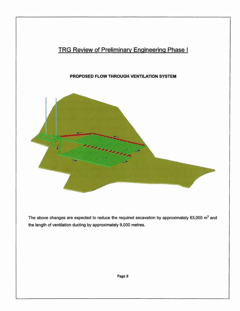
PROPOSED FLOW THROUGH VENTILATION SYSTEM
The above changes are expected to reduce the required excavation by approximately 63,000 m3 and
the length of ventilation ducting by approximately 9,000 metres.
Page 8
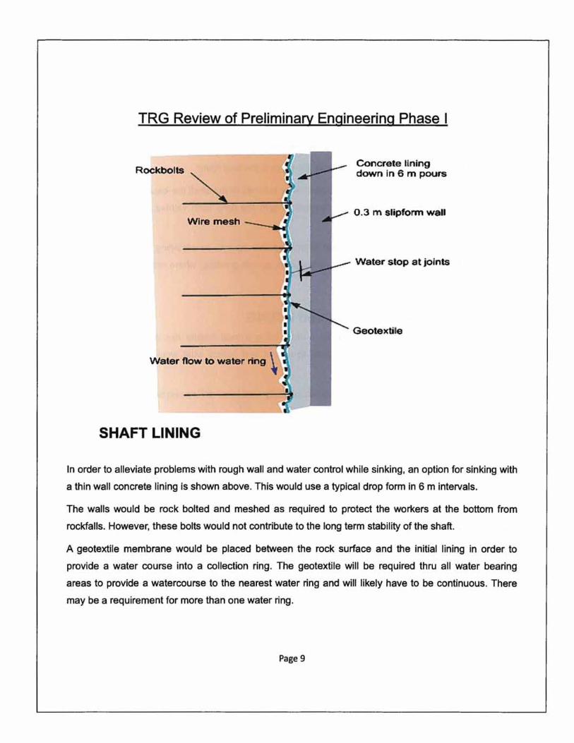
TRG Review of Preliminary Engineering Phase I
Rockbolts
Wire mesh
SHAFT LINING
Concrete tlning down in 6 m pours
0.3 m slipform wall
Water stop at joints
Geotextile
In order to alleviate problems with rough wall and water control while sinking, an option for sinking with
a thin wall concrete lining is shown above. This would use a typical drop form in 6 m intervals.
The walls would be rock bolted and meshed as required to protect the workers at the bottom from
rockfalls. However, these bolts would not contribute to the long term stability of the shaft.
A geotextile membrane would be placed between the rock surface and the initial lining in order to
provide a water course into a collection ring. The geotextile will be required thru all water bearing
areas to provide a watercourse to the nearest water ring and will likely have to be continuous. There
may be a requirement for more than one water ring.
Page 9
TRG Review of Preliminary Engineering Phase I
Waters stops would be used at cold joints between pours.
Dry wall grouting can be carried out prior to slip forming the final lining.
In the better quality impermeable rock in the lower reaches of the shaft the excavated diameter could
be reduced and the lining continued downwards with the drop form without the rock support and
geotextile layer.
This system allows a smooth shaft wall to jack against as well as providing a suitable surface for
installing pipes and Mary Ann guides. It also allows drywall grouting. where required. prior to slipform
lining.
SHAFT EXCAVATION and LINING Although it may be possible to excavate a shaft using a road header this approach has not been
proven yet and would entail high expense to design and supply what would be a one-off custom
design.
We believe that the EDZ can be minimized by carefully controlled drilling and blasting.
The Reach 1 zone could also be sunk using a slurry wall from surface. This approach is well proven
and possibly less expensive than the proposed method.
We believe that the use of a steel reinforced concrete liner will compromise the effectiveness of this
liner because water will permeate the concrete leading to rusting and subsequent swelling of the
rebar.
The proposed liner has only one seal boundary i.e. at the bottom of Reach 2. It is standard practice to
have another backup seal. perhaps at the bottom of. or part way down Reach 3. There should also be
facilities provided to detect leaks (Tell-tales ) and allow grouting behind the wall by embedding grout
pipes in the liner.
We foresee difficulties aligning the stage if the primary ground control is shotcrete. We recommend
drop-forming a thin inner liner on the way down to provide a secure and smooth surface to ensure
proper alignment of the stage. The final lining can then be slip formed over top.
Page 10
TRG Review of Preliminary Engineering Phase I
UNDERGROUND EXCAVATIONS
From the information and analyses that were made available for review it appears that the Cobourg
formation is tectonically undisturbed, very uniform, its strength is high in relation to the in situ stress
field. It appears to have relatively few adverse structural features and its permeability is very low.
These characteristics make it a favourable host rock for the construction of a stable waste repository.
Further testing and analyses are required to confirm these observations but the TRG is optimistic that
these conclusions will be shown to be valid.
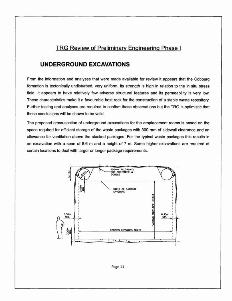
The proposed cross-section of underground excavations for the emplacement rooms is based on the
space required for efficient storage of the waste packages with 300 mm of sidewall clearance and an
allowance for ventilation above the stacked packages. For the typical waste packages this results in
an excavation with a span of 8.6 m and a height of 7 m. Some higher excavations are required at
certain locations to deal with larger or longer package requirements.
O.3Om
""- 150rnm ALLOWANCE T "--FOR SHOTCRETE ok
DOWELS
-- --- ,---------- ---- - -- ----- --: "'- UNITS OF PACKINC I
ENVElOPE
~ is O.3Om ~ ....::1oI=IN:.:..... ---=--+-;t ~ 11.
PACKING ENVELOPE VtlOTH
III ". ..
Page 11
TRG Review of Preliminary Engineering Phase I
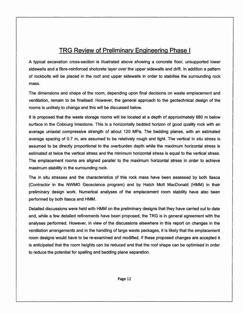
A typical excavation cross-section is illustrated above showing a concrete floor, unsupported lower
sidewalls and a fibre-reinforced shotcrete layer over the upper sidewalls and drift. In addition a pattern
of rockbolts will be placed in the roof and upper sidewalls in order to stabilise the surrounding rock
mass.
The dimensions and shape of the room, depending upon final decisions on waste emplacement and
ventilation, remain to be finalised. However, the general approach to the geotechnical design of the
rooms is unlikely to change and this will be discussed below.
It is proposed that the waste storage rooms will be located at a depth of approximately 680 m below
surface in the Cobourg limestone. This is a horizontally bedded horizon of good quality rock with an
average uniaxial compressive strength of about 120 MPa. The bedding planes, with an estimated
average spacing of 0.7 m, are assumed to be relatively rough and tight. The vertical in situ stress is
assumed to be directly proportional to the overburden depth while the maximum horizontal stress is
estimated at twice the vertical stress and the minimum horizontal stress is equal to the vertical stress.
The emplacement rooms are aligned parallel to the maximum horizontal stress in order to achieve
maximum stability in the surrounding rock.
The in situ stresses and the characteristics of this rock mass have been assessed by both Itasca
(Contractor in the NWMO Geoscience program) and by Hatch Mott MacDonald (HMM) in their
preliminary design work. Numerical analyses of the emplacement room stability have also been
performed by both Itasca and HMM.
Detailed discussions were held with HMM on the preliminary designs that they have carried out to date
and, while a few detailed refinements have been proposed, the TRG is in general agreement with the
analyses performed. However, in view of the discussions elsewhere in this report on changes in the
ventilation arrangements and in the handling of large waste packages, it is likely that the emplacement
room designs would have to be re-examined and modified. If these proposed changes are accepted it
is anticipated that the room heights can be reduced and that the roof shape can be optimised in order
to reduce the potential for spalling and bedding plane separation.
Page 12
TRG Review of Preliminary Engineering Phase I
FIRE The risk of fire will always be an important preoccupation in any underground setting. The TRG did not
see any evidence (although this may have been thoroughly considered by Hatch but not presented)
that this issue had been dealt with in sufficient detail, especially since the design group are hoping to
finalise the underground layout and the associated ventilation scheme as soon as possible. In our
opinion, these matters cannot be frozen until after there has been a complete simulation of all the
potential fire types and locations and only if these simulations show that the latest underground layout
and the ventilation schemes together are capable of satisfactorily protecting the life of all underground
workers. The designs should also include the appropriate fire detection systems, fire suppression
systems as well as the rescue stations (fixed and or mobile), fire doors etc. Potential fire locations
could include the shaft collar areas, the shafts, the repository level station, the services area
(especially the repair shop, the warehouse and the fuel storage site), the access drifts and in the dead
end emplacement rooms (during excavation and during filling). The simulations also need to consider
the possible location of any workers near a fire location. For example a worker could be either in front
of or behind a burning rubber tired truck or loader in a dead end emplacement room.
Recommendation: Prepare a simulation of possible fire events showing that the DGR is designed for
to cope with such events.
Page 13
TRG Review of Preliminary Engineering Phase I
MAIN CAGE and HOIST
Although the present design recommends a 6.0m diameter hoist the original six rope, 4.27m diameter
Koepe hoist would be adequate for handling the loads required. The options to increase the diameter
to 6.0m and the rope size from 42mm to 56mm are unnecessary.
Most Koepe hoists in North America now use low rotation, stranded headropes such as the Notorplast
design produced by Trefileurope. Low rotation is necessary to avoid scrubbing of the rope tread liners
through torque build up in the ropes.
The balance ropes must also be of a flexible design to avoid kinking at the tail-loop.
The main cage height could be drastically reduced if the T-H-E packages are kept below 4.6m in
height.
The main cage should be equipped with safety dogs. This will ensure that the cage cannot fall down
the shaft should the ropes fail ( this incident occurred at a potash mine in western Canada when a fire
annealed the headropes ). Safety dogs are required in California on all conveyances, even those
suspended by mult-ropes. Safety dogs designed to operate on HSS guides are in operation in many
installations in the USA.
Page 14
TRG Review of Preliminary Engineering Phase I
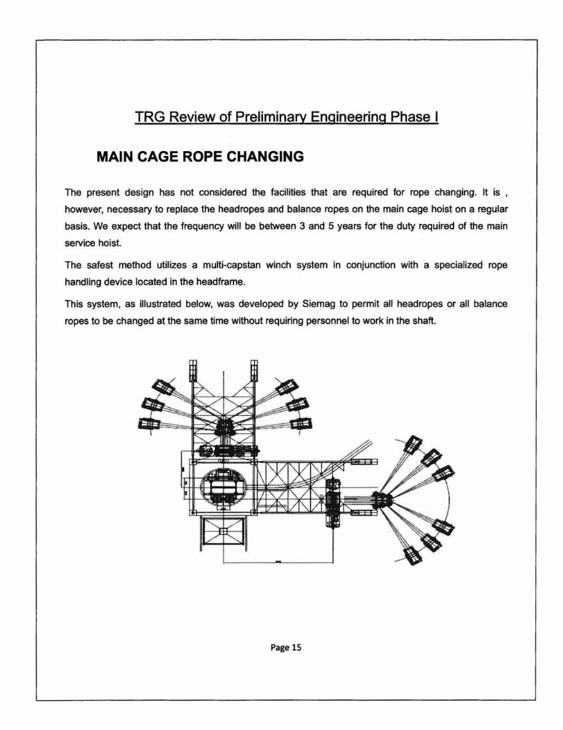
MAIN CAGE ROPE CHANGING
The present design has not considered the facilities that are required for rope changing. It is ,
however, necessary to replace the head ropes and balance ropes on the main cage hoist on a regular
basis. We expect that the frequency will be between 3 and 5 years for the duty required of the main
service hoist.
The safest method utilizes a multi-capstan winch system in conjunction with a specialized rope
handling device located in the headframe.
This system, as illustrated below, was developed by Siemag to permit all headropes or all balance
ropes to be changed at the same time without requiring personnel to work in the shaft.
Page 15
TRG Review of Preliminary Engineering Phase I
MAIN SHAFT AUXILIARY CAGE HOIST
The present design proposes using a single drum hoist to operate the auxiliary cage. This approach
will require the use of wooden guides and a cage equipped with dogs. These lead to problems in
maintenance and present a fire hazard.
The installation of a two rope Koepe with cage and counterweight will allow the use of steel guides
and avoid the necessity of dogs. This Koepe would be installed in the headframe at the same level as
the main hoist.
Page 16
TRG Review of Preliminary Engineering Phase I
VENTILATION SHAFT HOIST
The ventilation shaft will be the only means of developing the underground for about 8 months. As a
result the time available for hauling muck is only about 12 hours per day ( 50% per shift ). We estimate
that development will produce about 2 million tonnes of waste rock. This could be removed in 2 years
( say 700 days ). The daily rate is therefore about 3000 tonnes. The hoist will need to be equipped
with 8 tonne capacity skips in order to produce at this rate using 12 hours for production.
VENTILATION SHAFT LOADING STATION
The possible use of road headers to carry out the development means that the waste rock could be
small in size, wet and sticky. To avoid the muck hanging up in the waste pass it should be installed
vertically, directly below the grizzly. The pass will terminate over a pan feeder installed in a station
below the DGR level. This feeder will then discharge into measuring flasks at the shaft wall.
Grizzly
I I '\.. /
Pan Feeder
Measuring FLask
Page 17
TRG Review of Preliminary Engineering Phase I
ROAD HEADERS
Road headers have been proposed for application to both sinking the shaft ( Reach 3 ) and developing
the repository.
Application to Shaft Work The consensus among the review group is that this is not a viable option and is made even less
attractive as it is can only be used in Reach 3.
The machine would be a one-off design and would be a different design for each shaft if they remain
at the present dimensions of 4.Sm and 6.Sm diameter.
We believe that there is insufficient room to work with this machine in a shaft as small as 4.Sm
because of the space required on the shaft bottom for men and buckets. The presence of the boom
will also make probe hole drilling and cover grouting a major problem.
We also believe that it will be difficult to install ground support close to the bottom and also forsee a
major problem in supporting this machine. These devices require two sets of three large hydraulic feet
to support the structure and resist the massive torques produced by the cutting heads. These feet will
likely damage the ground support as the machine walks down the shaft.
In addition to the difficulties stated above the delivery of a machine will be about 2 years and high
cost.
Page 18

TRG Review of Preliminary Engineering Phase I
Application to Development The consensus on the use of road headers for lateral development is somewhat mixed as no one in
the TRG has personal experience with successful application of this machine in limestone for
development. Some members have, however, experienced poor performance of these machines in
what was thought to be reasonable conditions for their application.
We have contacted other personnel who have worked in limestone mines and have found the
productivity of road headers to be far below that of conventional drill and blast mining. The people we
have contacted also anticipate poor performance of these machines in rock that is not jointed and
layered. The Cobourg formation is free of both features and may therefore be difficult to break. A
summary of our correspondence with these users is provided in the Appendix.
The roader header option, if selected, means a large financial commitment to something which might
fail ( and failure is not an option ).
If road headers are used they will create a huge amount of dust. To eliminate the dust as much as
possible a large amount of water will have to be used to try to suppress the dust. The water will create
a wet sticky muck. The drill and blast approach, on other hand, eliminates both dust and wet sticky
muck as well as a pan feeder at the loading station. It will be possible to utilize a standard loading
arrangement with a conventional raise to a pair of lip pockets.
Unless there is a successful and representative test in a surface or near surface outcrop of the
Cobourg formation, the TRG is unanimous in its opinion that drill and blast techniques should be
selected for the lateral development ( as well as for the shaft sinking ).
Page 19
TRG Review of Preliminary Engineering Phase I
INTEGRATING A SINKING CONTRACTOR INTO THE DESIGN TEAM
The TRG concur 100% that integrating contractor experience into the design team early will be a real
plus for the project. However we are concerned that choosing one contractor from amongst 3 or 5
potential bidders to be a part of the design team (even if this contractor is subsequently dissociated
from the project a year or more before the bidding starts) has a high probability of discouraging one or
more of the other (not chosen) contractors to withdraw from the bidding process. This could have a
serious cost implication and in a worst case scenario leave the NWMO with only one bidder. A number
of the TRG members have previously worked as contractors and we have all at one time or another
declined to present a bid when we felt that another contractor had an inside track. This would certainly
be the assumption in case NWMO proceed as currently contemplated.
As an alternative we suggest that there are at several companies that could provide input to the
design team similar to that which would otherwise be provided by a contractor without offending any of
the potential bidders. We would further recommend that the firm so selected by the NWMO be
mandated to consult regularly (and confidentially) with those contractors that have (or are expected to
be) pre-selected by NWMO to bid the shaft work.
Recommendation: Give consideration to integrating an engineering firm qualified in the area of shaft
sinking and shaft design into the design team.
Alternately the NWMO could build up the Owner's team by hiring one or more individuals with the
requisite shaft design/sinking experience.
Page 20
TRG Review of Preliminary Engineering Phase I
VARIOUS
1. VENT DUCT: In the event that the disposal room ventilation scheme is maintained as
presented then two things might be considered: a) rolling the vent tubing underground and b)
installing the vent duct in such a way that it could be retrieved just prior to closing a room; this
would help reduce total vent duct cost AND would reduce the amount of steel in the rooms
susceptible to corrosion and the production of hydrogen gas
2. EMPLACEMENT ROOM HEIGHT: With detailed planning it should be possible to determine
the ultimate contents (which type of waste package) in most of the rooms. Hence it should be
possible to adjust the excavated back height of the rooms to height of the packages and of the
emplacement equipment (probably forklifts only if the TRG recommendations are adopted).
This should result in a significant reduction in room excavation costs.
3. DISPOSAL ROOM CONCRETE FLOORS: The TRG is concerned, but nevertheless believes,
that with lots of care and effort the quality of floor needed to successfully stack up to 6 or 7
waste packages can be constructed. However it needs to be noted that in the event that a drill
and blast method is adopted for the disposal room excavation it will be significantly more
difficult to construct a floor with the required tolerances. In fact with either excavation method a
small amount of non-uniform floor heave is to be expected and this will require excavation and
stabilisation before the concrete floor is cast. Stabilisation of the excavated floor can be
achieved by placing short grouted dowels which can also be used to anchor the concrete slab.
4. AUTOMATION AND ROBOTICS: Any operation that is under full manual control is more prone
to error (human) than a partially or fully automated process with multiple sensors, built in
redundancy and a failsafe design. A more automated process would probably increase the
public's confidence during hearings and give evidence of a more robust design. The design
team should consider looking for opportunities where some automation is practical.
Page 21
TRG Review of Preliminary Engineering Phase I
5. GROUTING AND PILOT HOLES: There are concerns that grout may travel between shafts
and that the shaft pilot holes will cause problems for sinking unless they are sequentially
grouted during the sinking program. If pilot holes are drilled in the shaft they will have to be
properly grouted to insure they do not provide a high inflow water course into the shaft while
sinking. These holes will have to be stage grouted as water is intersected when the holes are
drilled.
A second issue arises if one shaft advances ahead of the other; this will likely be the case.
When grouting the main shaft the grout may want to travel to the line of least resistance which
will likely be towards the vent shaft.
We highly recommend a grouting consultant be approached, such as Mr. Doug Morrison, who
is with Golder Associates Ltd.
6. VENTILATION SHAFT DIAMETER: The ventilation shaft diameter will need to be increased if
development ventilation is needed prior to the main shaft arriving at the level.
7. GROUTING: The grouting pattern will need to be reviewed (possibility of needing 3 drilling
Jumbos) and a surface grouting plant will be needed to feed them.
8. MINE RESCUE: A mine rescue team will be required with back-up from Goderich.
Page 22
TRG Review of Preliminary Engineering Phase I
APPENDIX - COMMENTS ON ROADHEADER EXCAVATION
Introduction
It has been proposed that the low- and mid-level waste repository rooms of the DGR should be
excavated by means of roadheaders. The Technical Review Group (TRG) unanimously recommends
against this option and favours the use of conventional drill and blast methods. The reasons for these
recommendations are discussed below.
Roadheader Experience
Roadheaders have been used on a number of civil engineering projects with varying success.
Important factors that have to be taken into account in deciding upon the suitability of roadheaders
are:
• Intact rock mass properties - roadheaders appear to have been most successful in rock with a
uniaxial compressive strength in the range of 50 to 80 MPa. In rocks of this strength, a uniform
rock mass with few significant structural features helps in the creation of stable openings and
road headers have been very successful in materials such as salt and potash.
• Claims that machines will cut massive rock with intact strengths of up to 120 MPa have to be
questioned since joints, bedding planes and other structural features will reduce the rock mass
strength significantly and it is this strength reduction that is exploited by the cutters. Cutting of
high strength rock with very few structural features, such as the Cobourg limestone, may be
possible but will result in high bit wear, the generation of fines rather than chips and in high
loading on the machine components.
• Dust generated during cutting is a health hazard and has to be dealt with by the provision of
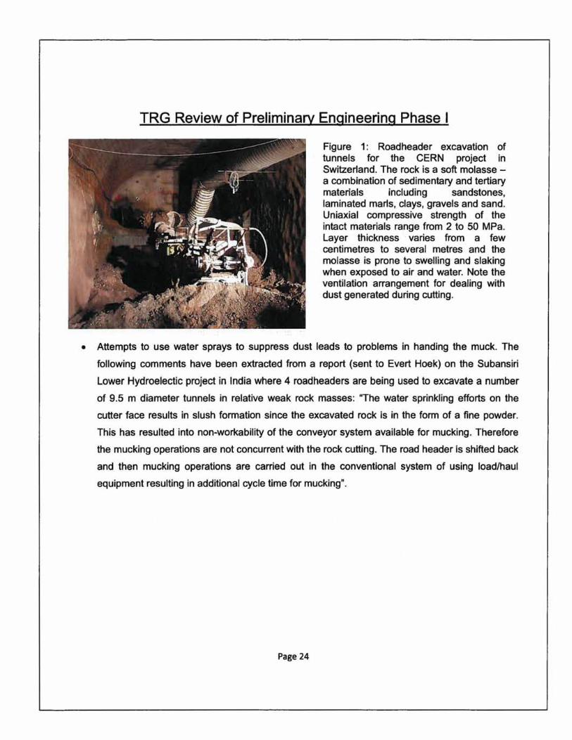
adequate ventilation for each road header as illustrated in Figure 1.
Page 23
TRG Review of Preliminary Engineering Phase I
Figure 1: Roadheader excavation of tunnels for the CERN project in Switzerland. The rock is a soft molasse -a combination of sedimentary and tertiary materials including sandstones, laminated marls, clays, gravels and sand. Uniaxial compressive strength of the intact materials range from 2 to 50 MPa. Layer thickness varies from a few centimetres to several metres and the molasse is prone to swelling and slaking when exposed to air and water. Note the ventilation arrangement for dealing with dust generated during cutting.
• Attempts to use water sprays to suppress dust leads to problems in handing the muck. The
following comments have been extracted from a report (sent to Evert Hoek) on the Subansiri
Lower Hydroelectic project in India where 4 roadheaders are being used to excavate a number
of 9.5 m diameter tunnels in relative weak rock masses: "The water sprinkling efforts on the
cutter face results in slush formation since the excavated rock is in the form of a fine powder.
This has resulted into non-workability of the conveyor system available for mucking. Therefore
the mucking operations are not concurrent with the rock cutting. The road header is shifted back
and then mucking operations are carried out in the conventional system of using load/haul
equipment resulting in additional cycle time for mucking".
Page 24
TRG Review of Preliminary Engineering Phase I
The following comments were offered, in an email to Peter Tiley dated 5 October 2009, by Mike
Marksberry, Director of Mine Engineering, Compass Minerals, 9900 West 109th Street, Suite 600,
Overland Park, KS 66210:
"I don't have direct experience with road headers in Limestone, but before I joined Lafarge the
technical people up in Montreal did a fair bit of work on using roadheaders in the mine instead of
drill/blast. They worked with the Colorado School of Mines and Voest-Alpine. At that time they
concluded that continuous mining wouldn't produce the same TPH as economically as drill/blast in
our limestone. The machines can definitely work in limestone, but they just felt in our particular
situation for production mining it would not be as cost effective. After I got on board and was
responsible for ordering the equipment I was not a real fan of "experimenting" with Lafarge's first
underground effort. We had a lot riding on it and I knew the "old-fashioned" way would work.
Not all limestone is the same, and there are big differences in compressive strength, chert content,
and rock mass. Rock mass is a big variable, and bedding, jointing, etc. has a lot to do with how it
will break and is probably more critical than compressive strength alone.
Lafarge bought an aggregate company up in Chicago several years ago and they used a
road header to develop a slope to a limestone formation, and then mined limestone with it for a
while to open up the area before production drill/blast began. From what I know it was quite
successful. The main guy behind it was a friend of mine and he now works for us. I will contact him
to find out more.
In short, it can definitely work, and I imagine there are a lot of civil jobs in similar materials where
they were successful. It depends on the unique geology and production rates trying to be obtained.
I'll get back to you if I learn more from my buddy.
Mike"
Page 25
TRG Review of Preliminary Engineering Phase I
In a follow-up email, dated 6 October 2009, Mike added the following comments:
"Massive limestone would be more difficult. You would have to cut it all without getting any
breaking from bedding or jointing. It would be slow, dusty, and consume a lot of bits. It can be
done though.
I talked more to my friend who used one in Chicago. He indicated that it worked OK, but they
switched over to drill and blast as soon as they could as the productivity was just too slow and the
product coming out of it didn't make a good aggregate.
He said the machine that he used, which is a Voest Alpine AM 105, was bought by another guy in
the Chicago area (Joliette) and he apparently is mining with it. From what my friend says this guy
likes to talk about it and is a real proponent of it , so you should give him a call.
You might even be able to go see it. The company is Mining International and the guys name is
Gary Smyth. The last number he had for him is 815-274-0303.
Mike"
Page 26
TRG Review of Preliminary Engineering Phase I
Conclusions
Based on their personal experience and on comments such as those quoted above, the TRG has
concluded that the suitability of roadheaders for the excavation of the waste repository rooms has not
been demonstrated in similar rock formations.
From the information presented to us for review it appears that the Cobourg limestone is a relatively
massive rock with few structural discontinuities. The average uniaxial compressive strength of the
intact limestone of 114 MPa within a range of strengths from 55 to 175 MPa (based on information
provided to the TRG during a briefing on the Geoscience Program) is at the upper end of the range of
rocks considered to be suitable for roadheader excavation. The scarcity of discontinuities to weaken
the rock mass suggests that the roadheader operation would be slow and costly in terms of bit, bit
holder and other equipment replacement.
The scarcity of discontinuities also means that the excavation process would be dominated by cutting
rather than chipping and that the resulting waste would be in the form of dust and fines. It is unlikely
that much of this material could be marketed as aggregate.
Dust generation during excavation is a health hazard which would have to be dealt with by ventilation
or by water sprays. High volume ventilation has to be provided for each roadheader and has to be
engineered to move with the roadheader as illustrated in Figure 1. Water sprays will result in the
formation of mud which, as described earlier, can have a negative impact on muck removal.
In view of the uncertainty associated with the operation of road headers in the Cobourg formation and
the practical difficulty of carrying realistic in situ trials before the decision on excavation method has to
be made, the TRG cannot support the proposal to use road headers for any of the excavations in the
DGR.
The TRG recommends that conventional drill and blast methods should be used for excavation of the
Page 27
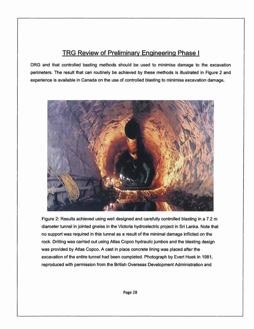
TRG Review of Preliminary Engineering Phase I
DRG and that controlled basting methods should be used to minimise damage to the excavation
perimeters. The result that can routinely be achieved by these methods is illustrated in Figure 2 and
experience is available in Canada on the use of controlled blasting to minimise excavation damage.
Figure 2: Results achieved using well designed and carefully controlled blasting in a 7.2 m
diameter tunnel in jointed gneiss in the Victoria hydroelectric project in Sri Lanka. Note that
no support was required in this tunnel as a result of the minimal damage inflicted on the
rock. Drilling was carried out using Atlas Copco hydraulic jumbos and the blasting design
was provided by Atlas Copco. A cast in place concrete lining was placed after the
excavation of the entire tunnel had been completed. Photograph by Evert Hoek in 1981,
reproduced with permission from the British Overseas Development Administration and
Page 28

TRG Review of Preliminary Engineering Phase I
from Balfour Beatty-Nuttall. Reference
http://www.rocscience.com/hoeklpdf/17 Blasting damage in rock. pdf.
Page 29