Embed Size (px)
Citation preview
Materials Services Infrastructure
Technical data from e+s and krings Shoring systemsTrench shoring: safety has top priority.
Every construction site has specific challenges that need to be mastered. However, the basic shoring requirements are always the same: a high level of safety, low impact on the soil surrounding the shoring, and as much working space as possible.
Our e+s and krings shoring systems ensure economical engineering process solutions for a wide range of civil engineering projects that cover all safety aspects, both at home and abroad – with almost 70 years of experience.
Unique expertise.thyssenkrupp Infrastructure is one of the best known companies in the field of trench shoring worldwide. We provide a broad range of trench shoring products and supplementary equipment. Our portfolio also includes temporary steel and plastic site road systems, the latter of which we also install. For many construction projects, the most economical solution is to hire the shoring system. We have an extensive stock of rental equipment and can offer our customers the ideal system for their requirements, even for large-scale projects.
ContentsSlide-rail systems 2e+s linear shoring 2krings parallel shoring 23 Shoring boxes 36System e+s 36System krings 57thyssenkrupp Aluminum lightweight shoring 79
Supplementary products for civil engineering 85
Trench shoring
Sliding rail systems
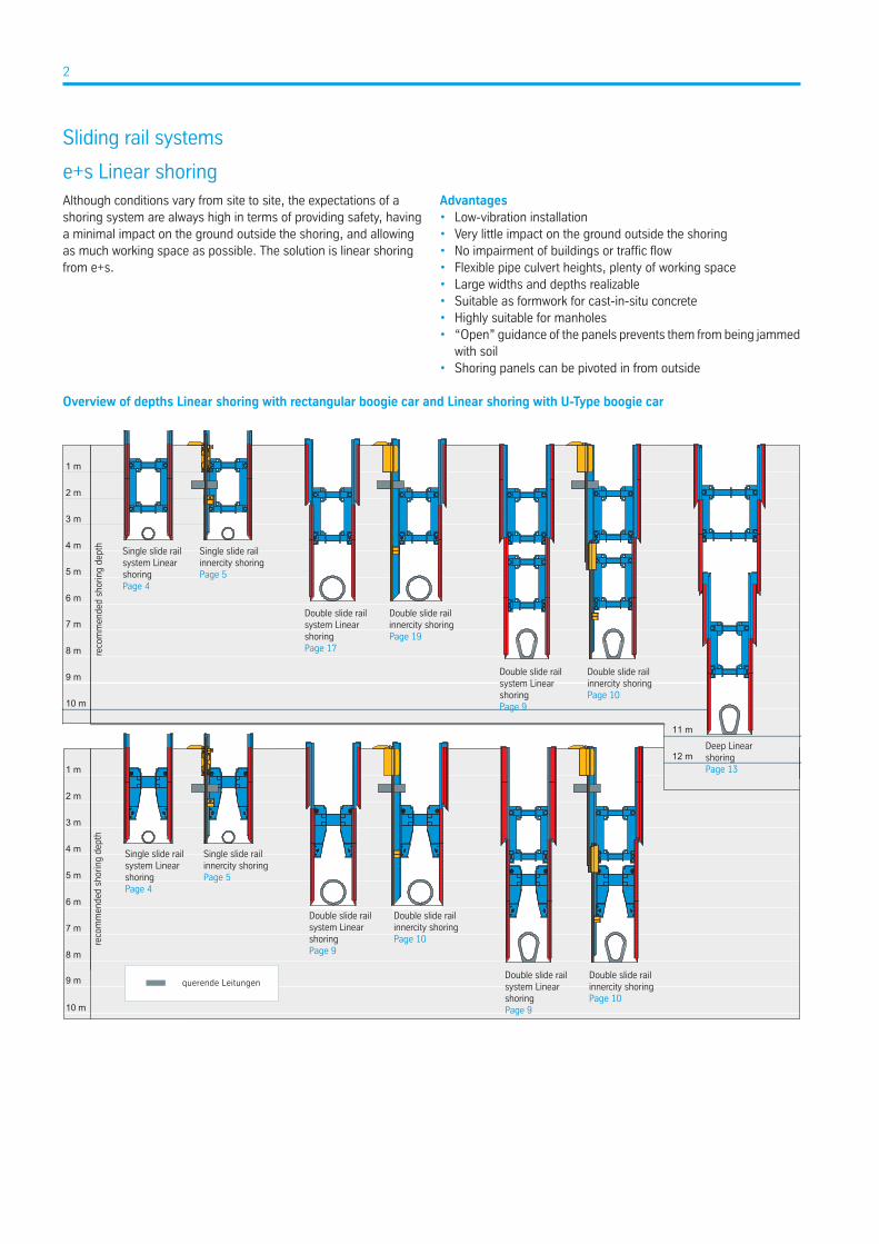
e+s Linear shoringAlthough conditions vary from site to site, the expectations of ashoring system are always high in terms of providing safety, havinga minimal impact on the ground outside the shoring, and allowingas much working space as possible. The solution is linear shoringfrom e+s.
Advantages• Low-vibration installation• Very little impact on the ground outside the shoring• No impairment of buildings or traffic flow• Flexible pipe culvert heights, plenty of working space• Large widths and depths realizable• Suitable as formwork for cast-in-situ concrete• Highly suitable for manholes• “Open” guidance of the panels prevents them from being jammed
with soil• Shoring panels can be pivoted in from outside
Overview of depths Linear shoring with rectangular boogie car and Linear shoring with U-Type boogie car
1 m
8 m
9 m
10 m
2 m
3 m
6 m
4 m
5 m
7 m
reco
mm
ende
d sh
orin
g de
pth
Single slide rail system Linear shoringPage 4
Single slide rail innercity shoringPage 5
Double slide rail system Linear shoringPage 9
Double slide rail innercity shoringPage 10
Double slide rail system Linear shoringPage 9
Double slide rail innercity shoringPage 10
7 m
1 m
2 m
8 m
5 m
6 m
4 m
3 m
9 m
11 m
12 m
10 m
reco
mm
ende
d sh
orin
g de
pth
Single slide rail system Linear shoringPage 4
Single slide rail innercity shoringPage 5
Double slide rail system Linear shoringPage 17
Double slide rail system Linear shoringPage 9
Deep Linear shoringPage 13
Double slide rail innercity shoringPage 19
Double slide rail innercity shoringPage 10
querende Leitungen
2
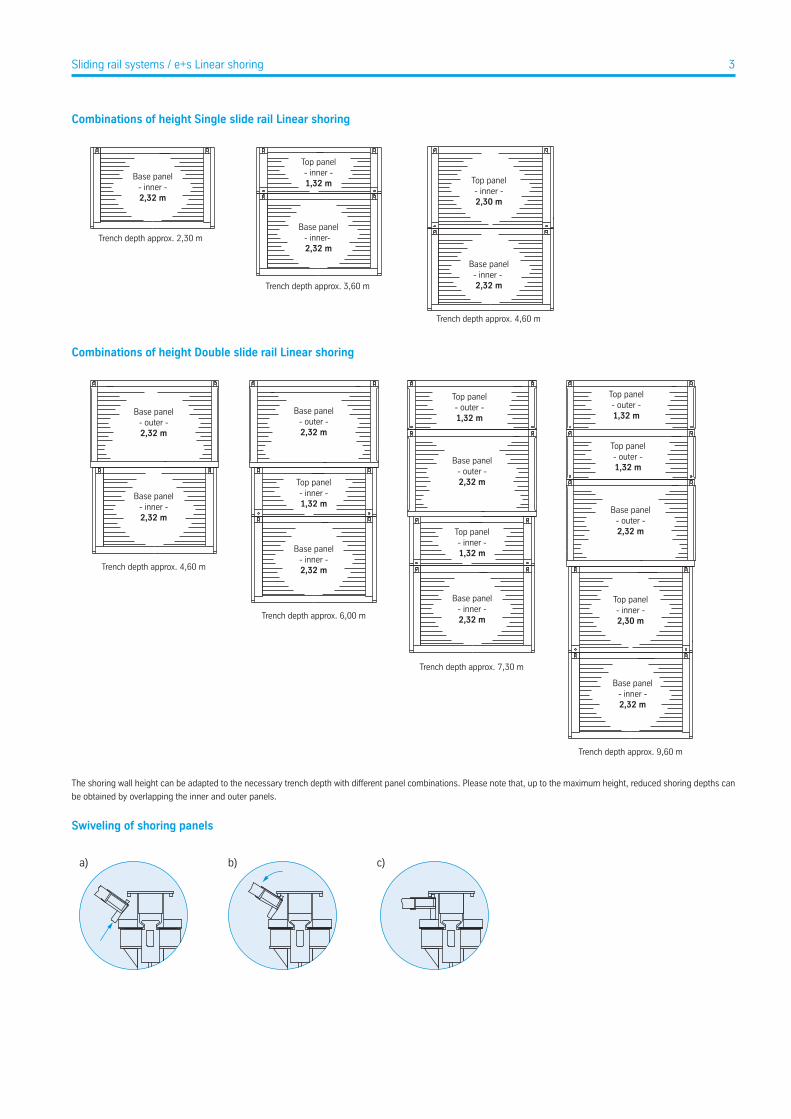
Combinations of height Single slide rail Linear shoring
Base panel- inner -2,32 m
Base panel- inner- 2,32 m
Top panel- inner -1,32 m
Base panel- inner - 2,32 m
Top panel- inner -2,30 m
Trench depth approx. 2,30 m
Trench depth approx. 3,60 m
Trench depth approx. 4,60 m
Combinations of height Double slide rail Linear shoring
Base panel- inner -2,32 m
Base panel- outer -2,32 m
Base panel- outer -2,32 m
Base panel- outer -2,32 m
Base panel- inner -2,32 m
Top panel- inner -1,32 m
Top panel- inner -2,30 m
Top panel- outer -1,32 m
Base panel- outer -2,32 m
Top panel- outer -1,32 m
Top panel- outer -1,32 m
Base panel- inner -2,32 m
Top panel- inner -1,32 m
Base panel- inner -2,32 m
Trench depth approx. 4,60 m
Trench depth approx. 6,00 m
Trench depth approx. 7,30 m
Trench depth approx. 9,60 m
The shoring wall height can be adapted to the necessary trench depth with different panel combinations. Please note that, up to the maximum height, reduced shoring depths can
be obtained by overlapping the inner and outer panels.
Swiveling of shoring panels
a) b) c)
3Sliding rail systems / e+s Linear shoring
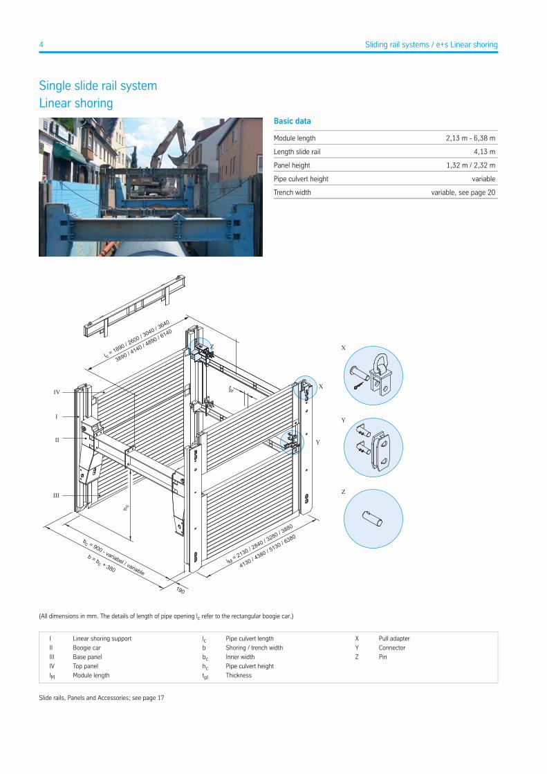
Single slide rail systemLinear shoring
Basic data
2,13 m - 6,38 mModule length
4,13 mLength slide rail
1,32 m / 2,32 mPanel height
variablePipe culvert height
variable, see page 20Trench width
X
Y
Z
IVX
Y
Z
I
II
III
bc = 900 - variabel / variable
b = bc + 380
190
lM = 2130 / 2840 / 3280 / 3880
4130 / 4380 / 5130 / 6380
h c
l c = 1890 / 2600 / 3040 / 3640
3890 / 4140 / 4890 / 6140
tpl
(All dimensions in mm. The details of length of pipe opening lc refer to the rectangular boogie car.)
Pull adapterXPipe culvert lengthlcLinear shoring supportI
ConnectorYShoring / trench widthbBoogie carII
PinZInner widthbcBase panelIII
Pipe culvert heighthcTop panelIV
ThicknesstplModule lengthlM
Slide rails, Panels and Accessories; see page 17
4 Sliding rail systems / e+s Linear shoring
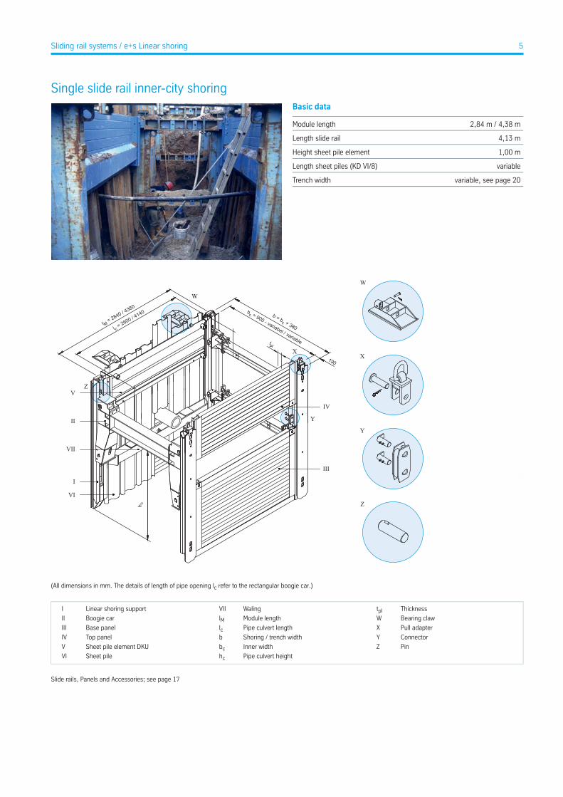
Single slide rail inner-city shoringBasic data
2,84 m / 4,38 mModule length
4,13 mLength slide rail
1,00 mHeight sheet pile element
variableLength sheet piles (KD VI/8)
variable, see page 20Trench width
X
W
Y
Z
190
b = bc + 380
bc = 900 - variabel / variable
l M = 2840 / 4380
l c = 2600 / 4
140
IV
III
VI
I
VII
II
V
h c
tplX
Y
Z
W
(All dimensions in mm. The details of length of pipe opening lc refer to the rectangular boogie car.)
ThicknesstplWalingVIILinear shoring supportI
Bearing clawWModule lengthlMBoogie carII
Pull adapterXPipe culvert lengthlcBase panelIII
ConnectorYShoring / trench widthbTop panelIV
PinZInner widthbcSheet pile element DKUV
Pipe culvert heighthcSheet pileVI
Slide rails, Panels and Accessories; see page 17
5Sliding rail systems / e+s Linear shoring
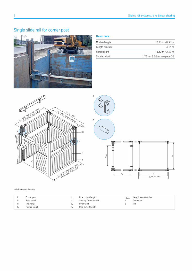
Single slide rail for corner postBasic data
2,13 m - 6,38 mModule length
4,13 mLength slide rail
1,32 m / 2,32 mPanel height
1,75 m - 6,00 m, see page 20Shoring width
Y
Z
b cl Zw
St
lM lclA = lc + 2 x 190
III
I
bc = 900 - variabel / variable
b = bc + 380
h c
II
190
l M = 2130 / 2840 / 3
280 / 3880
4130 / 4380 / 5
130 / 6380
l c = 1890 / 2
600 / 3040 / 3
640
3890 / 4140 / 4
890 / 6140
Y
Z
(All dimensions in mm)
Length extension barLZwStPipe culvert lengthlcCorner postI
ConnectorYShoring / trench widthbBase panelII
PinZInner widthbcTop panelIII
Pipe culvert heighthcModule lengthlM
6 Sliding rail systems / e+s Linear shoring
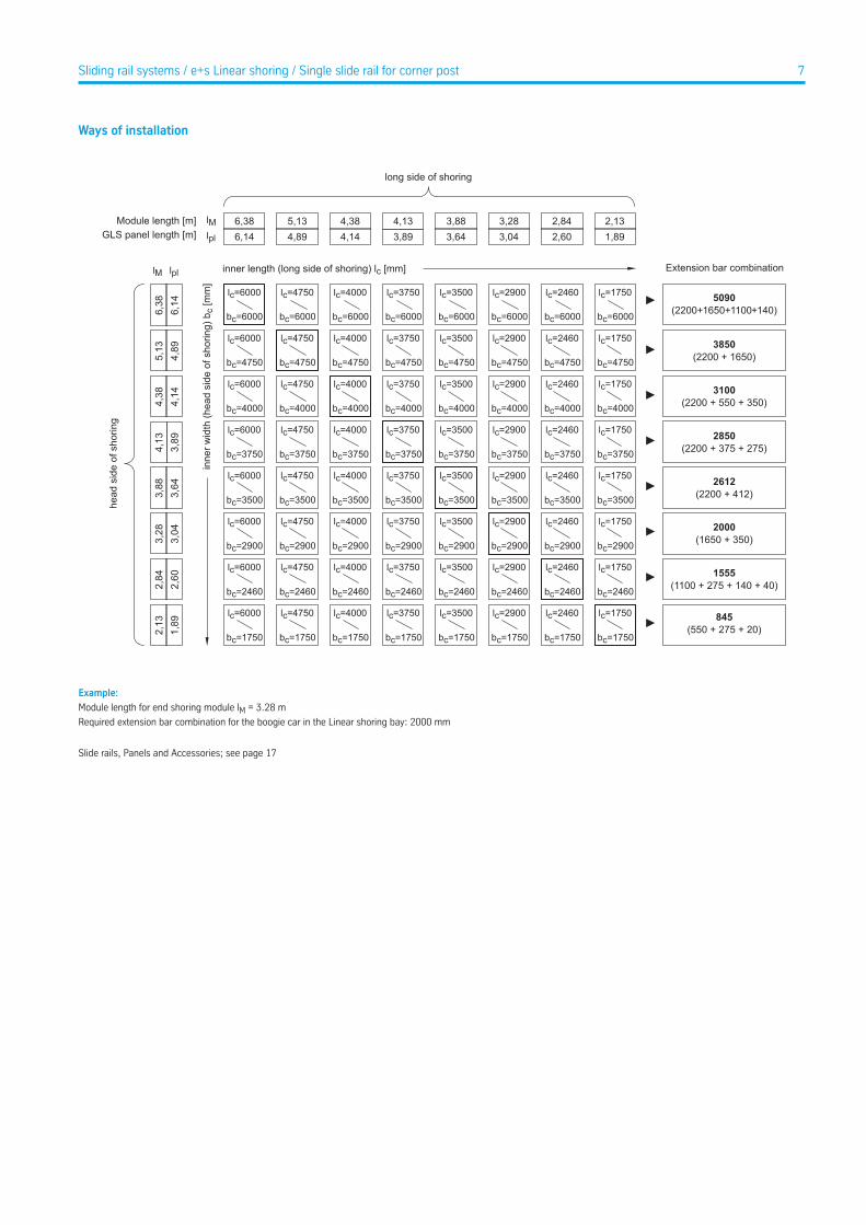
Ways of installation
Example:
Module length for end shoring module lM = 3.28 m
Required extension bar combination for the boogie car in the Linear shoring bay: 2000 mm
Slide rails, Panels and Accessories; see page 17
7Sliding rail systems / e+s Linear shoring / Single slide rail for corner post
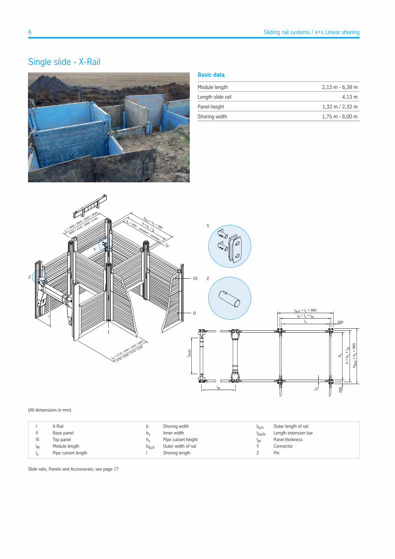
Single slide - X-RailBasic data
2,13 m - 6,38 mModule length
4,13 mLength slide rail
1,32 m / 2,32 mPanel height
1,75 m - 6,00 mShoring width
Y
Z III
I
II
l c = 1890 / 2
600 / 3040 / 3
640
3890 / 4140 / 4
890 / 6140
l M = 2130 / 2840 / 3
280 / 3880
4130 / 4380 / 5
130 / 6380
bc = 900 - variabel / variable
bSch = bc + 580b = bc + tpl
tpl
lSch = lc + 580lA = lc + tpl
lc
lM
l Zw
St
b Sch
= b
c +
580
b =
b c +
t pl
t pl
b c
290
290
Y
Z
(All dimensions in mm)
Outer length of raillSchShoring widthbX-RailI
Length extension barlZwStInner widthbcBase panelII
Panel thicknesstplPipe culvert heighthcTop panelIII
ConnectorYOuter width of railbSchModule lengthlMPinZShoring lengthlPipe culvert lengthlc
Slide rails, Panels and Accessories; see page 17
8 Sliding rail systems / e+s Linear shoring

Double slide rail systemLinear shoring
Basic data
2,25 m - 6,50 mModule length
5,13 m - 9,13 mLength slide rail
1,32 m / 2,32 mPanel height
variablePipe culvert height
variable, see page 20Trench width
tpl
b = bc + 640
bc = 900 - variabel / variable lM = 2250 / 2960 / 3400 / 4000
4250 / 4500 / 5250 / 6500
320
h c
III
I
II
IV
III
l c = 2000 / 2710 / 3150 / 3750
4000 / 4250 / 5000 / 6250
X
Z X
Y
Y Z
(All dimensions in mm. The details of length of pipe opening lc refer to the rectangular boogie car.)
Pull adapterXPipe culvert lengthlcLinear shoring supportI
ConnectorYShoring / trench widthbBoogie carII
PinZInner widthbcBase panelIII
Pipe culvert heighthcTop panelIV
ThicknesstplModule lengthlM
Slide rails, Panels and Accessories; see page 17
9Sliding rail systems / e+s Linear shoring
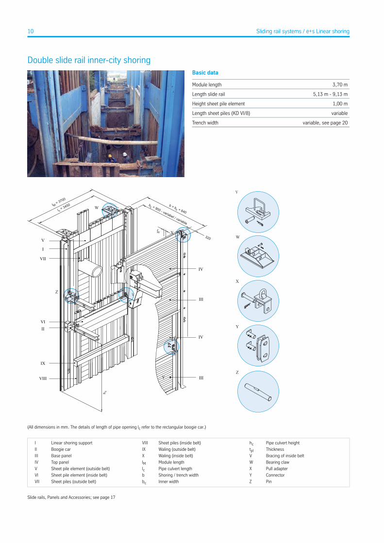
Double slide rail inner-city shoringBasic data
3,70 mModule length
5,13 m - 9,13 mLength slide rail
1,00 mHeight sheet pile element
variableLength sheet piles (KD VI/8)
variable, see page 20Trench width
X
Y
V
W
Z
b = bc + 640
bc = 900 - variabel / variable
320X
Y
Z
lM = 3700
l c = 3450
V
VII
I
IX
VIII
VIII
h c
III
IV
III
IV
W
V
tpl
(All dimensions in mm. The details of length of pipe opening lc refer to the rectangular boogie car.)
Pipe culvert heighthcSheet piles (inside belt)VIIILinear shoring supportI
ThicknesstplWaling (outside belt)IXBoogie carII
Bracing of inside beltVWaling (inside belt)XBase panelIII
Bearing clawWModule lengthlMTop panelIV
Pull adapterXPipe culvert lengthlcSheet pile element (outside belt)V
ConnectorYShoring / trench widthbSheet pile element (inside belt)VI
PinZInner widthbcSheet piles (outside belt)VII
Slide rails, Panels and Accessories; see page 17
10 Sliding rail systems / e+s Linear shoring
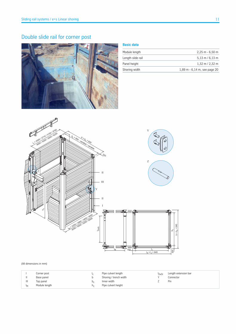
Double slide rail for corner postBasic data
2,25 m - 6,50 mModule length
5,13 m / 6,13 mLength slide rail
1,32 m / 2,32 mPanel height
1,89 m - 6,14 m, see page 20Shoring width
Y
Z
l M = 2250 / 2960 / 3
400 / 4000
4250 / 4
500 / 5250 / 6
500
I
II
II
III
l c = 2000 / 2
710 / 3150 / 3
750
4000 / 4
250 / 5000 / 6
250
320
bc = 900 - variabel / variable
b = bc + 640
h c
b c
b =
b c +
640
320320 lc
lA = lc + 640lM
l Zw
St
Y
Z
(All dimensions in mm)
Length extension barlZwStPipe culvert lengthlcCorner postI
ConnectorYShoring / trench widthbBase panelII
PinZInner widthbcTop panelIII
Pipe culvert heighthcModule lengthlM
11Sliding rail systems / e+s Linear shoring

Ways of installation
Example:
Module length for end shoring module lM = 3.40 m
Required extension bar combination for the boogie car in the Linear shoring bay: 2140 mm
12 Sliding rail systems / e+s Linear shoring / Double slide rail for corner post
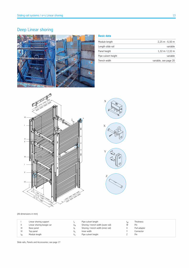
Deep Linear shoringBasic data
2,25 m - 6,50 mModule length
variableLength slide rail
1,32 m / 2,32 mPanel height
variablePipe culvert height
variable, see page 20Trench width
II
III
I
IV
III
I
II
III
X
Y
Z
X
Y
Z
X
4000 / 4
250 / 5000 / 6250
bc = 900 - variabel / variable
bI = b
c + 840bA = b
c + 1480
l c = 2000 / 2
710 / 3150 / 3750
l M =
2250 / 2960 / 3
400 / 4000
4250 / 4
500 / 5250 / 6500
320
420
tpl
h c
(All dimensions in mm)
ThicknesstplPipe culvert lengthlcLinear shoring supportI
PinWShoring / trench width (outer rail)bALinear shoring boogie carII
Pull adapterXShoring / trench width (inner rail)bIBase panelIII
ConnectorYInner widthbcTop panelIV
PinZPipe culvert heighthcModule lengthlM
Slide rails, Panels and Accessories; see page 17
13Sliding rail systems / e+s Linear shoring
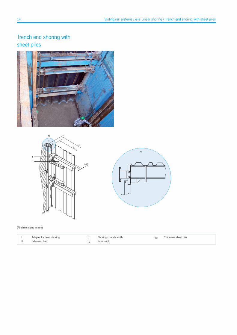
Trench end shoring withsheet piles
X
b
d KD
X
bc
I
II
(All dimensions in mm)
Thickness sheet piledKDShoring / trench widthbAdapter for head shoringI
Inner widthbcExtension barII
14 Sliding rail systems / e+s Linear shoring / Trench end shoring with sheet piles
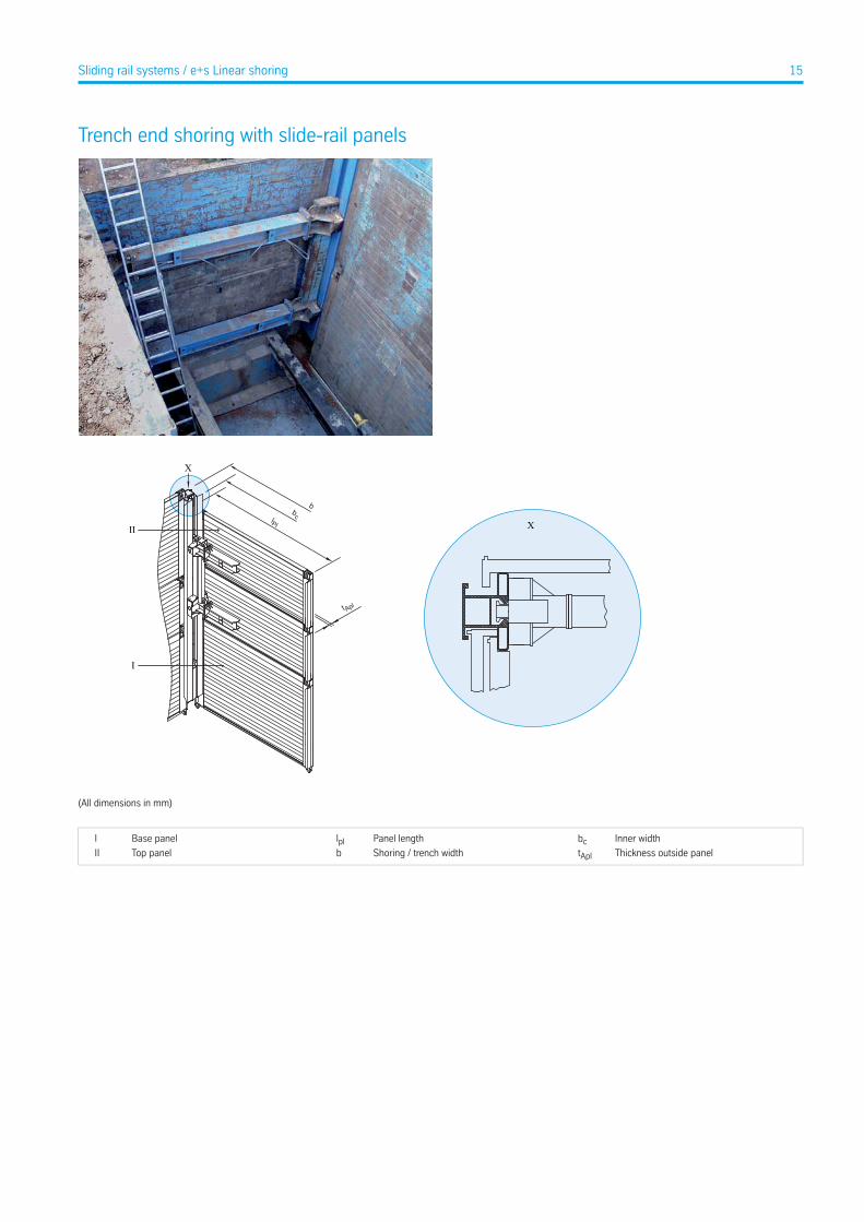
Trench end shoring with slide-rail panels
X
bc X
b lPl
II
I
t Apl
(All dimensions in mm)
Inner widthbcPanel lengthlplBase panelI
Thickness outside paneltAplShoring / trench widthbTop panelII
15Sliding rail systems / e+s Linear shoring
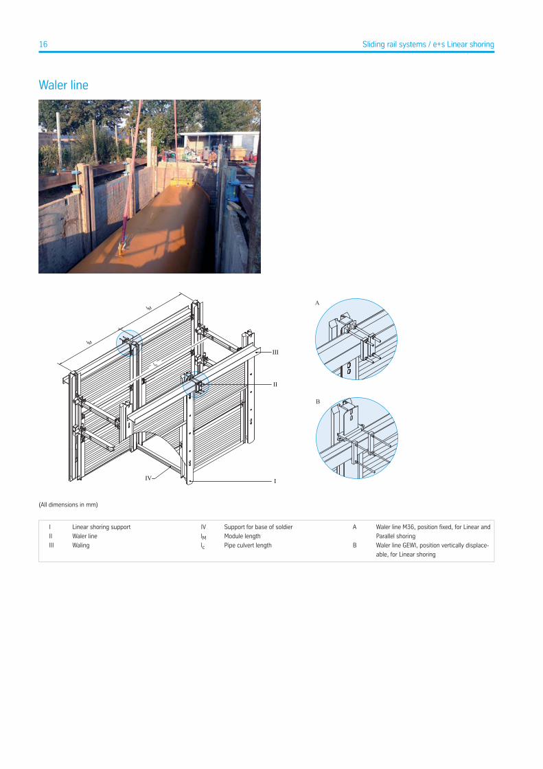
Waler line
B
II
I
III
IV
l M
l M
l c
A
(All dimensions in mm)
Waler line M36, position fixed, for Linear and
Parallel shoring
ASupport for base of soldierIVLinear shoring supportI
Module lengthlMWaler lineII
Waler line GEWI, position vertically displace-
able, for Linear shoring
BPipe culvert lengthlcWalingIII
16 Sliding rail systems / e+s Linear shoring
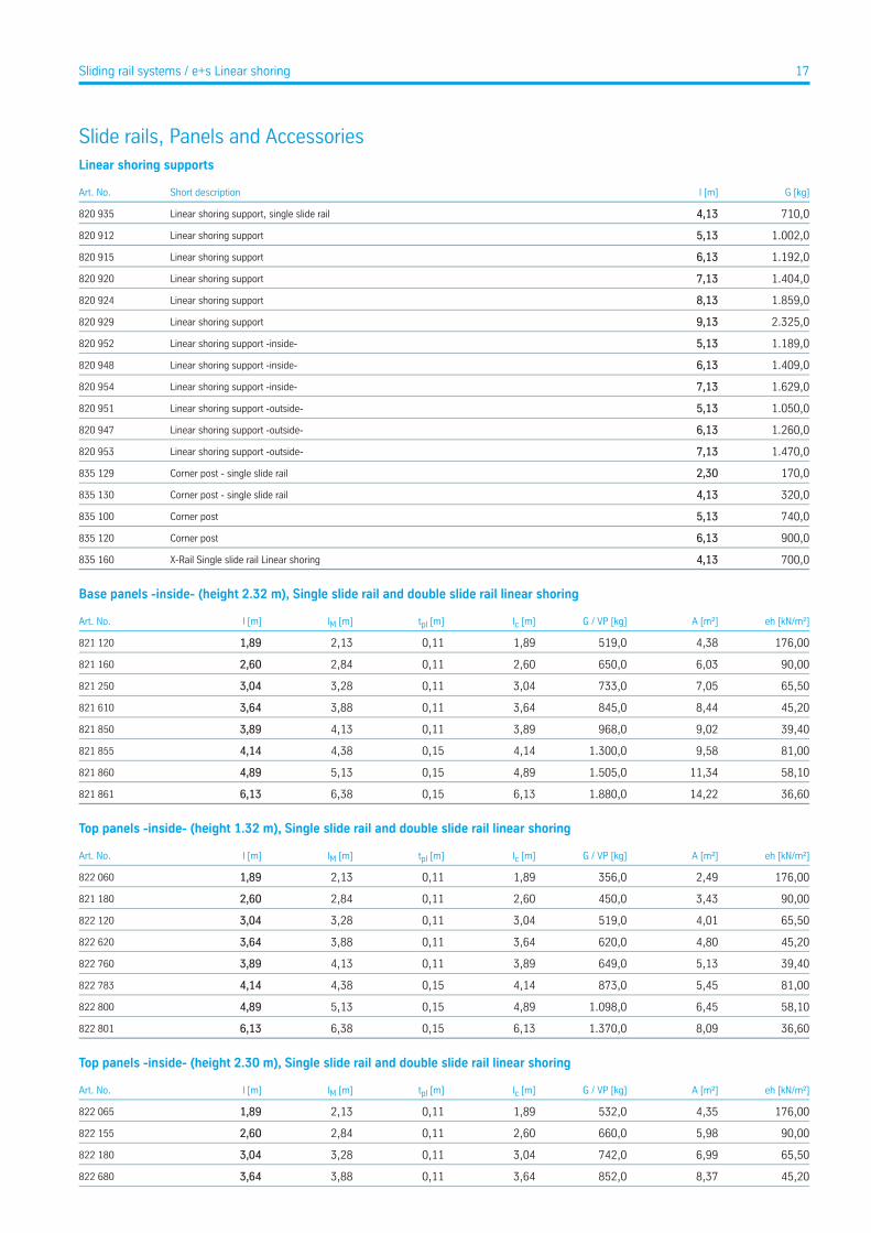
Slide rails, Panels and AccessoriesLinear shoring supports
G [kg]l [m]Short descriptionArt. No.
710,04,13Linear shoring support, single slide rail820 935
1.002,05,13Linear shoring support820 912
1.192,06,13Linear shoring support820 915
1.404,07,13Linear shoring support820 920
1.859,08,13Linear shoring support820 924
2.325,09,13Linear shoring support820 929
1.189,05,13Linear shoring support -inside-820 952
1.409,06,13Linear shoring support -inside-820 948
1.629,07,13Linear shoring support -inside-820 954
1.050,05,13Linear shoring support -outside-820 951
1.260,06,13Linear shoring support -outside-820 947
1.470,07,13Linear shoring support -outside-820 953
170,02,30Corner post - single slide rail835 129
320,04,13Corner post - single slide rail835 130
740,05,13Corner post835 100
900,06,13Corner post835 120
700,04,13X-Rail Single slide rail Linear shoring835 160
Base panels -inside- (height 2.32 m), Single slide rail and double slide rail linear shoring
eh [kN/m²]A [m²]G / VP [kg]lc [m]tpl [m]lM [m]l [m]Art. No.
176,004,38519,01,890,112,131,89821 120
90,006,03650,02,600,112,842,60821 160
65,507,05733,03,040,113,283,04821 250
45,208,44845,03,640,113,883,64821 610
39,409,02968,03,890,114,133,89821 850
81,009,581.300,04,140,154,384,14821 855
58,1011,341.505,04,890,155,134,89821 860
36,6014,221.880,06,130,156,386,13821 861
Top panels -inside- (height 1.32 m), Single slide rail and double slide rail linear shoring
eh [kN/m²]A [m²]G / VP [kg]lc [m]tpl [m]lM [m]l [m]Art. No.
176,002,49356,01,890,112,131,89822 060
90,003,43450,02,600,112,842,60821 180
65,504,01519,03,040,113,283,04822 120
45,204,80620,03,640,113,883,64822 620
39,405,13649,03,890,114,133,89822 760
81,005,45873,04,140,154,384,14822 783
58,106,451.098,04,890,155,134,89822 800
36,608,091.370,06,130,156,386,13822 801
Top panels -inside- (height 2.30 m), Single slide rail and double slide rail linear shoring
eh [kN/m²]A [m²]G / VP [kg]lc [m]tpl [m]lM [m]l [m]Art. No.
176,004,35532,01,890,112,131,89822 065
90,005,98660,02,600,112,842,60822 155
65,506,99742,03,040,113,283,04822 180
45,208,37852,03,640,113,883,64822 680
17Sliding rail systems / e+s Linear shoring
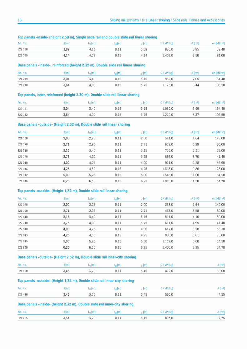
Top panels -inside- (height 2.30 m), Single slide rail and double slide rail linear shoring
eh [kN/m²]A [m²]G / VP [kg]lc [m]tpl [m]lM [m]l [m]Art. No.
39,408,95980,03,890,114,133,89822 780
81,009,501.409,04,140,154,384,14822 785
Base panels -inside-, reinforced (height 2.32 m), Double slide rail linear shoring
eh [kN/m²]A [m²]G / VP [kg]lc [m]tpl [m]lM [m]l [m]Art. No.
154,407,05982,03,150,153,403,04821 249
106,508,441.125,03,750,154,003,64821 248
Top panels, inner, reinforced (height 2.30 m), Double slide rail linear shoring
eh [kN/m²]A [m²]G / VP [kg]lc [m]tpl [m]lM [m]l [m]Art. No.
154,406,991.080,03,150,153,403,04822 181
106,508,371.220,03,750,154,003,64822 182
Base panels -outside- (Height 2,32 m), Double slide rail linear shoring
eh [kN/m²]A [m²]G / VP [kg]lc [m]tpl [m]lM [m]l [m]Art. No.
149,004,64541,02,000,112,252,00821 150
80,006,29672,02,710,112,962,71821 170
59,007,31755,03,150,113,403,15821 310
41,408,70865,03,750,114,003,75821 770
36,609,28911,04,000,114,254,00821 910
75,009,861.313,04,250,154,504,25821 913
54,5011,601.545,05,000,155,255,00821 912
34,7014,501.910,06,250,156,506,25821 916
Top panels -outside- (Height 1,32 m), Double slide rail linear shoring
eh [kN/m²]A [m²]G / VP [kg]lc [m]tpl [m]lM [m]l [m]Art. No.
149,002,64368,02,000,112,252,00822 075
80,003,58453,02,710,112,962,71821 190
59,004,16511,03,150,113,403,15822 310
41,404,95611,03,750,114,003,75822 710
36,305,28647,04,000,114,254,00822 810
75,005,61900,04,250,154,504,25822 813
54,506,601.137,05,000,155,255,00822 815
34,708,251.400,06,250,156,506,25822 830
Base panels -outside- (Height 2,32 m), Double slide rail inner-city shoring
A [m²]G / VP [kg]lc [m]tpl [m]lM [m]l [m]Art. No.
8,00812,03,450,113,703,45821 320
Top panels -outside- (Height 1,32 m), Double slide rail inner-city shoring
A [m²]G / VP [kg]lc [m]tpl [m]lM [m]l [m]Art. No.
4,55560,03,450,113,703,45822 410
Base panels -inside- (height 2.32 m), Double slide rail inner-city shoring
A [m²]G / VP [kg]lc [m]tpl [m]lM [m]l [m]Art. No.
7,75803,03,450,113,703,34821 255
18 Sliding rail systems / e+s Linear shoring / Slide rails, Panels and Accessories
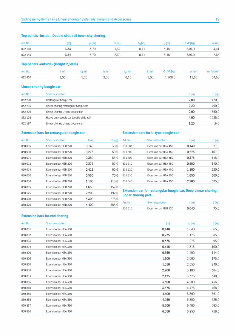
Top panels -inside-, Double slide rail inner-city shoring
A [m²]G / VP [kg]lc [m]tpl [m]h [m]lM [m]l [m]Art. No.
4,41570,03,450,111,323,703,34822 140
7,68840,03,450,112,303,703,34822 145
Top panels -outside- (Height 2,30 m)
eh [kN/m²]A [m²]G / VP [kg]lc [m]tpl [m]h [m]lM [m]l [m]Art. No.
54,5011,501.700,05,000,152,305,255,00822 820
Linear shoring boogie car
G [kg]l [m]Short descriptionArt. No.
420,02,00Rectangular boogie car832 200
490,02,20Linear shoring rectangular boogie car832 215
550,02,00Linear shoring U-type boogie car832 205
1925,04,00Heavy-duty boogie car (double slide-rail)832 198
3401,20Linear shoring U-type boogie car832 197
Extension bars for rectangular boogie car
G [kg]l [m]Short descriptionArt. No.
38,00,140Extension bar HEB 220830 005
50,00,275Extension bar HEB 220830 010
55,00,350Extension bar HEB 220830 011
57,00,375Extension bar HEB 220830 012
60,00,412Extension bar HEB 220830 015
70,00,550Extension bar HEB 220830 020
110,01,100Extension bar HEB 220830 030
152,01,650Extension bar HEB 220830 075
192,02,200Extension bar HEB 220830 125
278,03,300Extension bar HEB 220830 300
358,04,400Extension bar HEB 220830 305
Extension bars for U-type boogie car
G [kg]l [m]Short descriptionArt. No.
77,00,140Extension bar HEA 450831 503
107,00,275Extension bar HEA 450831 500
115,00,375Extension bar HEA 450831 507
140,00,550Extension bar HEA 450831 510
220,01,100Extension bar HEA 450831 520
300,01,650Extension bar HEA 450831 530
375,02,200Extension bar HEA 450831 540
Extension bar for rectangular boogie car, Deep Linear shoring;upper shoring part
G [kg]l [m]Short descriptionArt. No.
75,00,640Extension bar HEB 220830 310
Extension bars for end shoring
G [kg]bc [m]l [m]Short descriptionArt. No.
65,01,0400,140Extension bar HEA 360830 801
85,01,1750,275Extension bar HEA 360830 802
95,01,2750,375Extension bar HEA 360830 803
100,01,3150,415Extension bar HEA 360830 804
114,01,4500,550Extension bar HEA 360830 800
175,02,0001,100Extension bar HEA 360830 806
240,02,5501,650Extension bar HEA 360830 810
304,03,1002,200Extension bar HEA 360830 830
340,03,3752,475Extension bar HEA 360830 833
436,04,2003,300Extension bar HEA 360830 836
468,04,4753,575Extension bar HEA 360830 840
561,05,3004,400Extension bar HEA 360830 850
626,05,8504,950Extension bar HEA 360830 855
693,06,4005,500Extension bar HEA 360830 857
758,06,9506,050Extension bar HEA 360830 860
19Sliding rail systems / e+s Linear shoring / Slide rails, Panels and Accessories
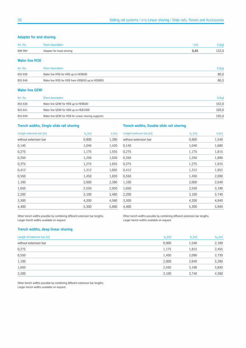
Adapter for end shoring
G [kg]l [m]Short descriptionArt. No.
132,00,45Adapter for head shoring899 994
Waler line M36
G [kg]Short descriptionArt. No.
80,0Waler line M36 for HEB up to HEB600855 836
86,5Waler line M36 for HEB from HEB650 up to HEB800855 846
Waler line GEWI
G [kg]Short descriptionArt. No.
162,0Waler line GEWI for HEB up to HEB600855 838
169,0Waler line GEWI for HEB up to HEB1000855 841
195,0Waler line GEWI for HEB for Linear shoring supports855 839
Trench widths, Single slide rail shoring
b [m]bc [m]Length extension bar [m]
1,2800,900without extension bar
1,4201,0400,140
1,5551,1750,275
1,6301,2500,350
1,6551,2750,375
1,6921,3120,412
1,8301,4500,550
2,3802,0001,100
2,9302,5501,650
3,4803,1002,200
4,5804,2003,300
5,6805,3004,400
Other trench widths possible by combining different extension bar lengths.
Larger trench widths available on request.
Trench widths, Double slide rail shoring
b [m]bc [m]Length extension bar [m]
1,5400,900without extension bar
1,6801,0400,140
1,8151,1750,275
1,8901,2500,350
1,9151,2750,375
1,9521,3120,412
2,0901,4500,550
2,6402,0001,100
3,1902,5501,650
3,7403,1002,200
4,8404,2003,300
5,9405,3004,400
Other trench widths possible by combining different extension bar lengths.
Larger trench widths available on request.
Trench widths, deep linear shoring
bA [m]bI [m]bc [m]Length of extension bar [m]
2,1801,5400,900without extension bar
2,4551,8151,1750,275
2,7302,0901,4500,550
3,2802,6402,0001,100
3,8303,1902,5501,650
4,3803,7403,1002,200
Other trench widths possible by combining different extension bar lengths.
Larger trench widths available on request.
20 Sliding rail systems / e+s Linear shoring / Slide rails, Panels and Accessories
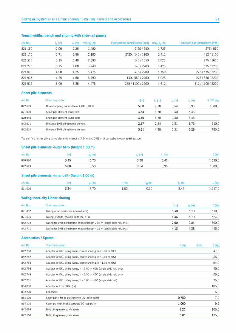
Trench widths, trench end shoring with slide-rail panels
Extension bar combinations [mm]max. bc [m]Extension bar combinations [mm]min. bc [m]lM [m]lpl [m]Art. No.
275 / 5501,7252*20 / 5501,4902,252,00821 150
412 / 11002,4122*20 / 140 / 11002,1802,962,71821 170
275 / 16502,825140 / 16502,6903,403,15821 310
375 / 22003,475140 / 22003,2404,003,75821 770
275 / 375 / 22003,750375 / 22003,4754,254,00821 910
275 / 550 / 22003,925140 / 550 / 22003,7904,504,25821 913
412 / 1100 / 22004,612275 / 1100 / 22004,4755,255,00821 912
Sheet pile elements
G / VP [kg]lc [m]tpl [m]lM [m]l [m]Short descriptionArt. No.
1880,05,950,546,385,80Universal piling frame element, DKE, KD VI842 699
3,450,303,703,34Sheet pile element (inner belt)821 000
3,450,303,703,45Sheet pile element (outer belt)820 980
510,01,750,312,842,27Universal DKU piling frame element842 671
785,03,290,314,383,81Universal DKU piling frame element842 674
You can find further piling frame elements in lengths 3.64 m and 3.89 m at our website www.es-krings.com
Sheet pile elements -outer belt- (height 1.00 m)
G [kg]lc [m]tpl [m]lM [m]l [m]Art. No.
1.330,03,450,303,703,45820 980
1880,05,950,546,505,80842 699
Sheet pile elements -inner belt- (height 1.00 m)
G [kg]lc [m]tpl [m]h [m]lM [m]l [m]Art. No.
1.217,03,450,301,003,703,34821 000
Waling inner-city Linear shoring
G [kg]lM [m]l [m]Short descriptionArt. No.
310,03,703,30Waling -inside- (double slide rail, e+s)821 002
374,03,703,46Waling -outside- (double slide rail, e+s)821 003
300,02,842,60Waling for DKU piling frame, module length 2.84 m (single slide rail, e+s)842 704
445,04,384,13Waling for DKU piling frame, module length 4.38 m (single slide rail, e+s)842 711
Accessories / Spares
G [kg]d [m]l [m]Short descriptionArt. No.
47,0Adapter for DKU piling frame, corner shoring, h = 0.50 m KDIV842 758
55,0Adapter for DKU piling frame, corner shoring, h = 0.50 m KDVI842 752
94,0Adapter for DKU piling frame, corner shoring, h = 1.00 m KDVI842 753
40,0Adapter for DKU piling frame, h = 0.50 m KDIV (single slide rail, e+s)842 759
45,0Adapter for DKU piling frame, h = 0.50 m KDVI (single slide rail, e+s)842 749
75,5Adapter for DKU piling frame, h = 1.00 m KDVI (single slide rail)842 751
105,0Adapter for EGS / DGS (LV)834 080
5,5Connector862 200
7,90,750Cover panel for in-situ concrete DG -base panel-834 100
9,91,000Cover plate for in-situ concrete DG -top plate-834 110
105,02,27DKU piling frame guide frame842 099
175,03,81DKU piling frame guide frame842 100
21Sliding rail systems / e+s Linear shoring / Slide rails, Panels and Accessories
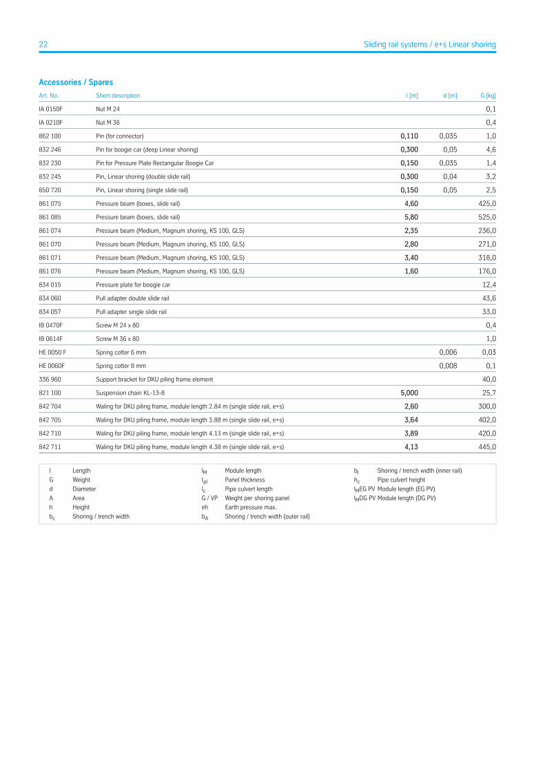
Accessories / Spares
G [kg]d [m]l [m]Short descriptionArt. No.
0,1Nut M 24IA 0150F
0,4Nut M 36IA 0210F
1,00,0350,110Pin (for connector)862 100
4,60,050,300Pin for boogie car (deep Linear shoring)832 246
1,40,0350,150Pin for Pressure Plate Rectangular Boogie Car832 230
3,20,040,300Pin, Linear shoring (double slide rail)832 245
2,50,050,150Pin, Linear shoring (single slide rail)850 720
425,04,60Pressure beam (boxes, slide rail)861 075
525,05,80Pressure beam (boxes, slide rail)861 085
236,02,35Pressure beam (Medium, Magnum shoring, KS 100, GLS)861 074
271,02,80Pressure beam (Medium, Magnum shoring, KS 100, GLS)861 070
318,03,40Pressure beam (Medium, Magnum shoring, KS 100, GLS)861 071
176,01,60Pressure beam (Medium, Magnum shoring, KS 100, GLS)861 076
12,4Pressure plate for boogie car834 015
43,6Pull adapter double slide rail834 060
33,0Pull adapter single slide rail834 057
0,4Screw M 24 x 80IB 0470F
1,0Screw M 36 x 80IB 0614F
0,030,006Spring cotter 6 mmHE 0050 F
0,10,008Spring cotter 8 mmHE 0060F
40,0Support bracket for DKU piling frame element336 960
25,75,000Suspension chain KL-13-8821 100
300,02,60Waling for DKU piling frame, module length 2.84 m (single slide rail, e+s)842 704
402,03,64Waling for DKU piling frame, module length 3.88 m (single slide rail, e+s)842 705
420,03,89Waling for DKU piling frame, module length 4.13 m (single slide rail, e+s)842 710
445,04,13Waling for DKU piling frame, module length 4.38 m (single slide rail, e+s)842 711
Shoring / trench width (inner rail)bIModule lengthlMLengthl
Pipe culvert heighthcPanel thicknesstplWeightG
Module length (EG PV)lMEG PVPipe culvert lengthlcDiameterd
Module length (DG PV)lMDG PVWeight per shoring panelG / VPAreaA
Earth pressure max.ehHeighth
Shoring / trench width (outer rail)bAShoring / trench widthbc
22 Sliding rail systems / e+s Linear shoring

krings Parallel shoring
Advantages
• Low-vibration installation• Very little impact on the surrounding ground• No impairment of buildings or traffic flow• Flexible pipe culvert heights, plenty of work space• Large widths and depths feasible• Suitable as formwork for in-situ concrete• Highly suitable for manholes
.
Overview of depths Parallel shoring with rectangular boogie car and Parallel shoring with U-Type boogie car
1 m
6 m
5 m
4 m
3 m
2 m
1 m
6 m
7 m
5 m
4 m
3 m
2 m
reco
mm
ende
d sh
orin
g de
pth
reco
mm
ende
d sh
orin
g de
pth
Single slide rail system parallel shoringPage 25
Single slide-rail inner-city parallel shoringPage 26
Double slide rail system parallel shoringPage 27
Double slide rail inner-city parallel shoring
Single slide rail system parallel shoringPage 25
Single slide-rail inner-city parallel shoringPage 26
Double slide rail system parallel shoringPage 27
Double slide rail inner-city parallel shoring
7 m
crossing supply lines
23Sliding rail systems
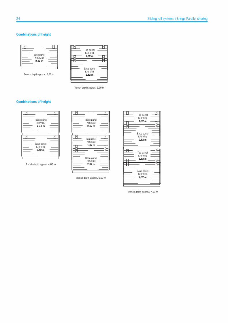
Combinations of height
Trench depth approx. 2,30 m
Base panelKRI/KRU2,32 m
Trench depth approx. 3,60 m
Top panelKRI/KRU1,32 m
Base panelKRI/KRU2,32 m
Combinations of height
Trench depth approx. 4,60 m
Base panelKRI/KRU2,32 m
Base panelKRI/KRU2,32 m
Base-panelKRI/KRU2,32 m
Base-panelKRI/KRU2,32 m
Top panelKRI/KRU1,32 m
Top panelKRI/KRU1,32 m
Base panelKRI/KRU2,32 m
Top panelKRI/KRU1,32 m
Base panelKRI/KRU2,32 mTrench depth approx. 6,00 m
Trench depth approx. 7,30 m
24 Sliding rail systems / krings Parallel shoring
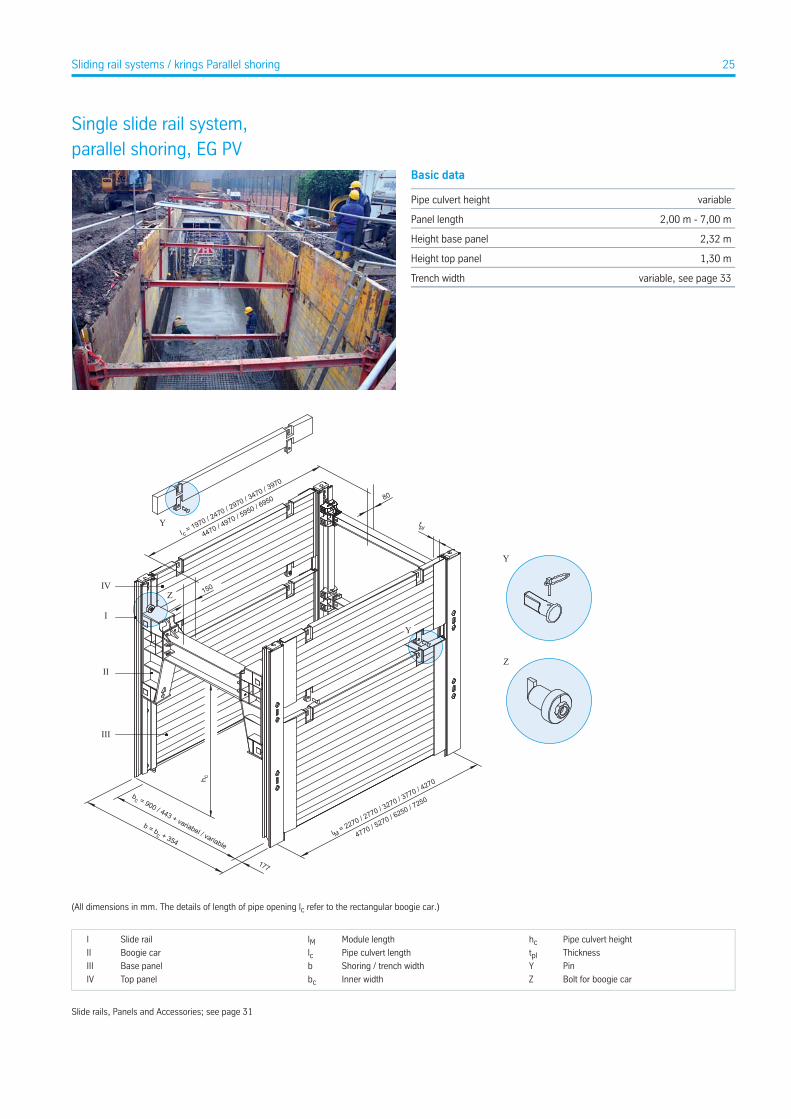
Single slide rail system,parallel shoring, EG PV
Basic data
variablePipe culvert height
2,00 m - 7,00 mPanel length
2,32 mHeight base panel
1,30 mHeight top panel
variable, see page 33Trench width
Y
Y
Y
Z
ZIV
I
II
III
tpl
h c
bc = 900 / 443 + variabel / variable
b = bc + 354
177
l M = 2270 / 2770 / 3270 / 3770 / 4270
4770 / 5270 / 6250 / 7250
l c = 1970 / 2470 / 2970 / 3470 / 3970
80
150
4470 / 4970 / 5950 / 6950
(All dimensions in mm. The details of length of pipe opening lc refer to the rectangular boogie car.)
Pipe culvert heighthcModule lengthlMSlide railI
ThicknesstplPipe culvert lengthlcBoogie carII
PinYShoring / trench widthbBase panelIII
Bolt for boogie carZInner widthbcTop panelIV
Slide rails, Panels and Accessories; see page 31
25Sliding rail systems / krings Parallel shoring
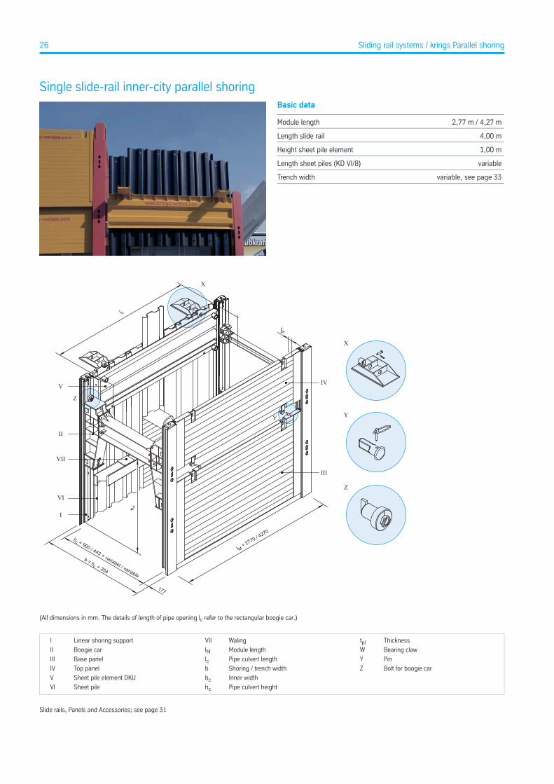
Single slide-rail inner-city parallel shoringBasic data
2,77 m / 4,27 mModule length
4,00 mLength slide rail
1,00 mHeight sheet pile element
variableLength sheet piles (KD VI/8)
variable, see page 33Trench width
X
Y
l M = 2770 / 4270
tpl
bc = 900 / 443 + variabel / variable
b = bc + 354
177
VI
I
II
V
VII
IV
III
h c
l c
Y
Z
Z
X
(All dimensions in mm. The details of length of pipe opening lc refer to the rectangular boogie car.)
ThicknesstplWalingVIILinear shoring supportI
Bearing clawWModule lengthlMBoogie carII
PinYPipe culvert lengthlcBase panelIII
Bolt for boogie carZShoring / trench widthbTop panelIV
Inner widthbcSheet pile element DKUV
Pipe culvert heighthcSheet pileVI
Slide rails, Panels and Accessories; see page 31
26 Sliding rail systems / krings Parallel shoring
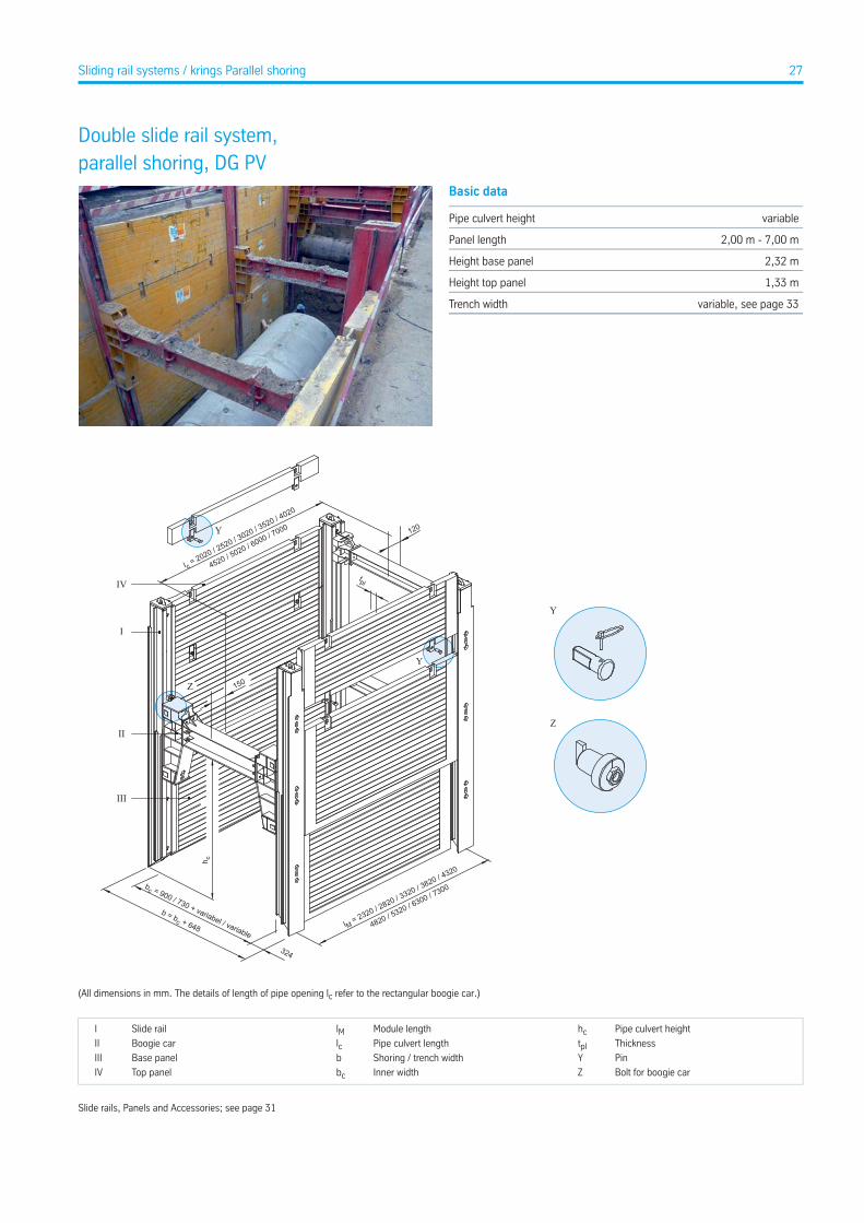
Double slide rail system,parallel shoring, DG PV
Basic data
variablePipe culvert height
2,00 m - 7,00 mPanel length
2,32 mHeight base panel
1,33 mHeight top panel
variable, see page 33Trench width
120
150
Y
Y
Z
IV
II
III
I
tpl
l c = 2020 / 2520 / 3020 / 3520 / 4020
4520 / 5020 / 6000 / 7000
h c
bc = 900 / 730 + variabel / variable
b = bc + 648 lM = 2320 / 2820 / 3320 / 3820 / 4320
4820 / 5320 / 6300 / 7300
324
Y
Z
(All dimensions in mm. The details of length of pipe opening lc refer to the rectangular boogie car.)
Pipe culvert heighthcModule lengthlMSlide railI
ThicknesstplPipe culvert lengthlcBoogie carII
PinYShoring / trench widthbBase panelIII
Bolt for boogie carZInner widthbcTop panelIV
Slide rails, Panels and Accessories; see page 31
27Sliding rail systems / krings Parallel shoring
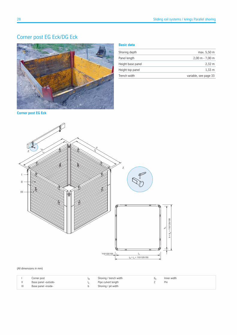
Corner post EG Eck/DG EckBasic data
max. 5,50 mShoring depth
2,00 m - 7,00 mPanel length
2,32 mHeight base panel
1,33 mHeight top panel
variable, see page 33Trench width
Corner post EG Eck
Z
III
II
I
l Al c
bc
b
Z
b =
b c +
110
/125
/150
b c
lA = lc + 110/125/150
110/125/150 lc
(All dimensions in mm)
Inner widthbcShoring / trench widthlACorner postI
PinZPipe culvert lengthlcBase panel -outside-II
Shoring / pit widthbBase panel -inside-III
28 Sliding rail systems / krings Parallel shoring

Corner post DG Eck
III
270
270
lA = lc + 540
b =
b c +
540
lc
b c
II
I
l Al c
bc
b
Z
Z
(All dimensions in mm)
Inner widthbcShoring / trench widthlACorner postI
PinZPipe culvert lengthlcBase panel -outside-II
Shoring / pit widthbBase panel -inside-III
29Sliding rail systems / krings Parallel shoring / Corner post EG Eck/DG Eck
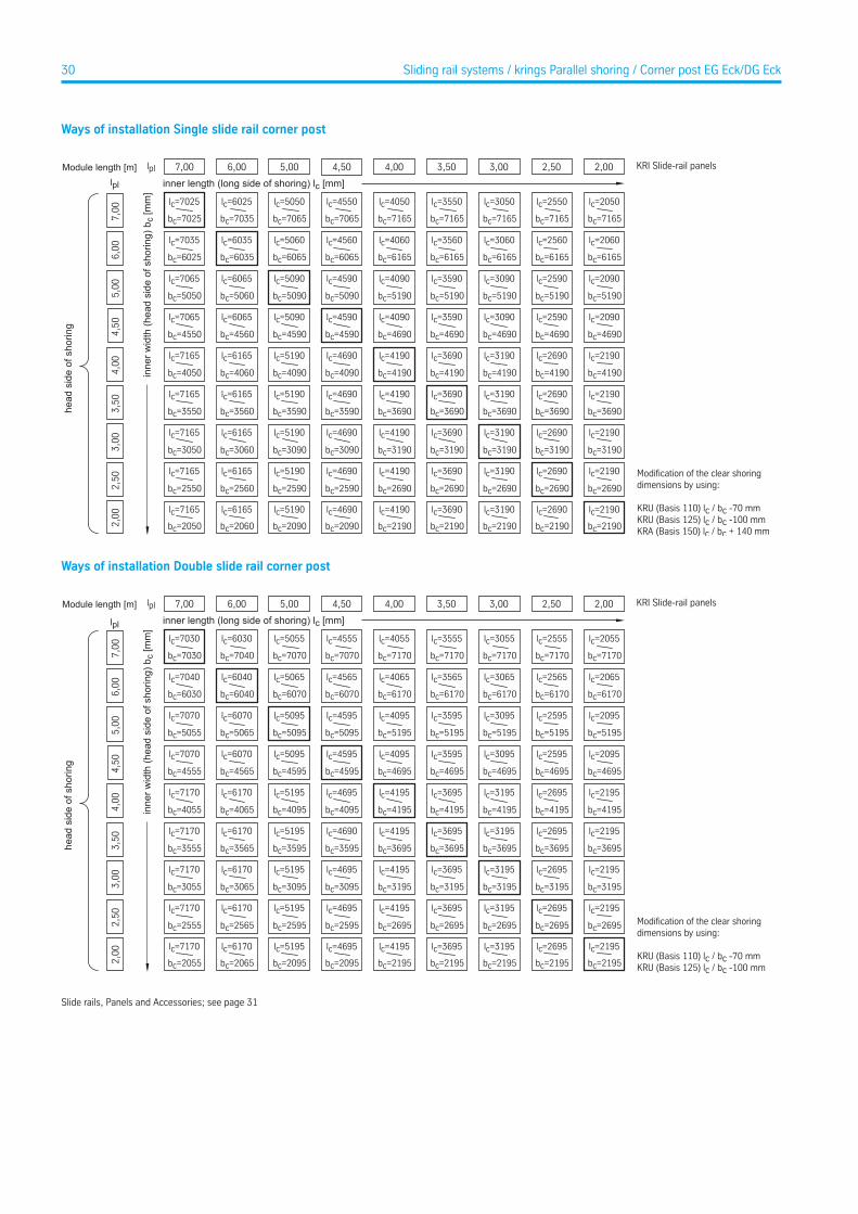
Ways of installation Single slide rail corner post
lpl
lpl 2,506,007,00 4,50 4,00 3,50 3,005,00
lc=7025 lc=6025 lc=5050 lc=4550 lc=4050 lc=3550 lc=3050 lc=2550
lc=7035 lc=6035 lc=5060 lc=4560 lc=4060 lc=3560 lc=3060 lc=2560
lc=7065 lc=6065 lc=5090 lc=4590 lc=4090 lc=3590 lc=3090 lc=2590
lc=7065 lc=6065 lc=5090 lc=4590 lc=4090 lc=3590 lc=3090 lc=2590
lc=7165 lc=6165 lc=5190 lc=4690 lc=4190 lc=3690 lc=3190 lc=2690
lc=7165 lc=6165 lc=5190 lc=4690 lc=4190 lc=3690 lc=3190 lc=2690
lc=7165 lc=6165 lc=5190 lc=4690 lc=4190 lc=3690 lc=3190 lc=2690
lc=7165 lc=6165 lc=5190 lc=4690 lc=4190 lc=3690 lc=3190 lc=2690
6,00
7,00
5,00
4,50
4,00
3,50
3,00
2,50
2,00
2,00
bc=7025
bc=6025
bc=5050
bc=4550
bc=4050
bc=3550
bc=3050
bc=2550
bc=2050
bc=7035
bc=6035
bc=5060
bc=4560
bc=4060
bc=3560
bc=3060
bc=2560
bc=2060
bc=7065
bc=6065
bc=5090
bc=4590
bc=4090
bc=3590
bc=3090
bc=2590
bc=2090
bc=7065
bc=6065
bc=5090
bc=4590
bc=4090
bc=3590
bc=3090
bc=2590
bc=2090
bc=7165
bc=6165
bc=5190
bc=4690
bc=4190
bc=3690
bc=3190
bc=2690
bc=2190
bc=7165
bc=6165
bc=5190
bc=4690
bc=4190
bc=3690
bc=3190
bc=2690
bc=2190
bc=7165
bc=6165
bc=5190
bc=4690
bc=4190
bc=3690
bc=3190
bc=2690
bc=2190
bc=7165
bc=6165
bc=5190
bc=4690
bc=4190
bc=3690
bc=3190
bc=2690
bc=2190
lc=2050
lc=2060
lc=2090
lc=2090
lc=2190
lc=2190
lc=2190
lc=2190
bc=7165
bc=6165
bc=5190
bc=4690
bc=4190
bc=3690
bc=3190
bc=2690
bc=2190
lc=7165 lc=6165 lc=5190 lc=4690 lc=4190 lc=3690 lc=3190 lc=2690 lc=2190
inne
r wid
th (h
ead
side
of s
horin
g) b
c [m
m]
Module length [m]
inner length (long side of shoring) lc [mm]
head
sid
e of
sho
ring
dimensions by using:
KRU (Basis 110) lc / bc -70 mmKRU (Basis 125) lc / bc -100 mmKRA (Basis 150) lc / bc + 140 mm
KRI Slide-rail panels
Ways of installation Double slide rail corner post
lpl
lpl 2,506,007,00 4,50 4,00 3,50 3,005,00
lc=7030 lc=6030 lc=5055 lc=4555 lc=4055 lc=3555 lc=3055 lc=2555
lc=7040 lc=6040 lc=5065 lc=4565 lc=4065 lc=3565 lc=3065 lc=2565
lc=7070 lc=6070 lc=5095 lc=4595 lc=4095 lc=3595 lc=3095 lc=2595
lc=7070 lc=6070 lc=5095 lc=4595 lc=4095 lc=3595 lc=3095 lc=2595
lc=7170 lc=6170 lc=5195 lc=4695 lc=4195 lc=3695 lc=3195 lc=2695
lc=7170 lc=6170 lc=5195 lc=4690 lc=4195 lc=3695 lc=3195 lc=2695
lc=7170 lc=6170 lc=5195 lc=4695 lc=4195 lc=3695 lc=3195 lc=2695
lc=7170 lc=6170 lc=5195 lc=4695 lc=4195 lc=3695 lc=3195 lc=2695
6,00
7,00
5,00
4,50
4,00
3,50
3,00
2,50
2,00
2,00
bc=7030
bc=6030
bc=5055
bc=4555
bc=4055
bc=3555
bc=3055
bc=2555
bc=2055
bc=7040
bc=6040
bc=5065
bc=4565
bc=4065
bc=3565
bc=3065
bc=2565
bc=2065
bc=7070
bc=6070
bc=5095
bc=4595
bc=4095
bc=3595
bc=3095
bc=2595
bc=2095
bc=7070
bc=6070
bc=5095
bc=4595
bc=4095
bc=3595
bc=3095
bc=2595
bc=2095
bc=7170
bc=6170
bc=5195
bc=4695
bc=4195
bc=3695
bc=3195
bc=2695
bc=2195
bc=7170
bc=6170
bc=5195
bc=4695
bc=4195
bc=3695
bc=3195
bc=2695
bc=2195
bc=7170
bc=6170
bc=5195
bc=4695
bc=4195
bc=3695
bc=3195
bc=2695
bc=2195
bc=7170
bc=6170
bc=5195
bc=4695
bc=4195
bc=3695
bc=3195
bc=2695
bc=2195
lc=2055
lc=2065
lc=2095
lc=2095
lc=2195
lc=2195
lc=2195
lc=2195
bc=7170
bc=6170
bc=5195
bc=4695
bc=4195
bc=3695
bc=3195
bc=2695
bc=2195
lc=7170 lc=6170 lc=5195 lc=4695 lc=4195 lc=3695 lc=3195 lc=2695 lc=2195
inne
r wid
th (h
ead
side
of s
horin
g) b
c [m
m]
Module length [m]
inner length (long side of shoring) lc [mm]
head
sid
e of
sho
ring
KRI Slide-rail panels
dimensions by using:
KRU (Basis 110) lc / bc -70 mmKRU (Basis 125) lc / bc -100 mm
Slide rails, Panels and Accessories; see page 31
30 Sliding rail systems / krings Parallel shoring / Corner post EG Eck/DG Eck
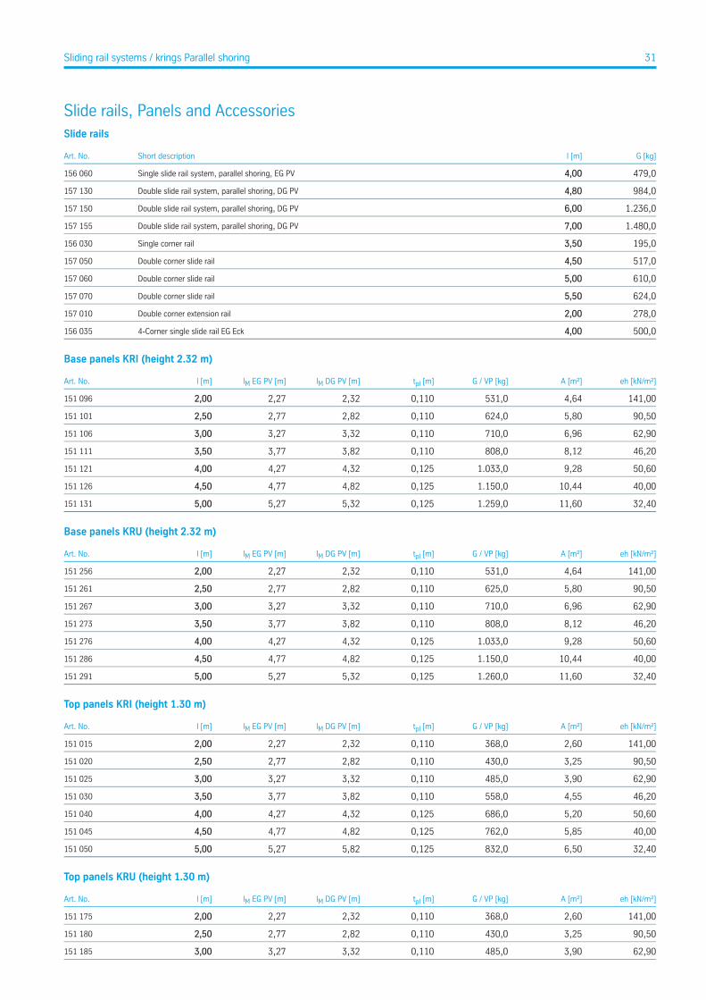
Slide rails, Panels and AccessoriesSlide rails
G [kg]l [m]Short descriptionArt. No.
479,04,00Single slide rail system, parallel shoring, EG PV156 060
984,04,80Double slide rail system, parallel shoring, DG PV157 130
1.236,06,00Double slide rail system, parallel shoring, DG PV157 150
1.480,07,00Double slide rail system, parallel shoring, DG PV157 155
195,03,50Single corner rail156 030
517,04,50Double corner slide rail157 050
610,05,00Double corner slide rail157 060
624,05,50Double corner slide rail157 070
278,02,00Double corner extension rail157 010
500,04,004-Corner single slide rail EG Eck156 035
Base panels KRI (height 2.32 m)
eh [kN/m²]A [m²]G / VP [kg]tpl [m]lM DG PV [m]lM EG PV [m]l [m]Art. No.
141,004,64531,00,1102,322,272,00151 096
90,505,80624,00,1102,822,772,50151 101
62,906,96710,00,1103,323,273,00151 106
46,208,12808,00,1103,823,773,50151 111
50,609,281.033,00,1254,324,274,00151 121
40,0010,441.150,00,1254,824,774,50151 126
32,4011,601.259,00,1255,325,275,00151 131
Base panels KRU (height 2.32 m)
eh [kN/m²]A [m²]G / VP [kg]tpl [m]lM DG PV [m]lM EG PV [m]l [m]Art. No.
141,004,64531,00,1102,322,272,00151 256
90,505,80625,00,1102,822,772,50151 261
62,906,96710,00,1103,323,273,00151 267
46,208,12808,00,1103,823,773,50151 273
50,609,281.033,00,1254,324,274,00151 276
40,0010,441.150,00,1254,824,774,50151 286
32,4011,601.260,00,1255,325,275,00151 291
Top panels KRI (height 1.30 m)
eh [kN/m²]A [m²]G / VP [kg]tpl [m]lM DG PV [m]lM EG PV [m]l [m]Art. No.
141,002,60368,00,1102,322,272,00151 015
90,503,25430,00,1102,822,772,50151 020
62,903,90485,00,1103,323,273,00151 025
46,204,55558,00,1103,823,773,50151 030
50,605,20686,00,1254,324,274,00151 040
40,005,85762,00,1254,824,774,50151 045
32,406,50832,00,1255,825,275,00151 050
Top panels KRU (height 1.30 m)
eh [kN/m²]A [m²]G / VP [kg]tpl [m]lM DG PV [m]lM EG PV [m]l [m]Art. No.
141,002,60368,00,1102,322,272,00151 175
90,503,25430,00,1102,822,772,50151 180
62,903,90485,00,1103,323,273,00151 185
31Sliding rail systems / krings Parallel shoring
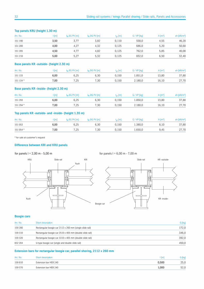
Top panels KRU (height 1.30 m)
eh [kN/m²]A [m²]G / VP [kg]tpl [m]lM DG PV [m]lM EG PV [m]l [m]Art. No.
46,204,55558,00,1103,823,773,50151 190
50,605,20686,00,1254,324,274,00151 200
40,005,85762,00,1254,824,774,50151 205
32,406,50832,00,1255,325,275,00151 210
Base panels KR -outside- (height 2.30 m)
eh [kN/m²]A [m²]G / VP [kg]tpl [m]lM DG PV [m]lM EG PV [m]l [m]Art. No.
37,8013,801.851,00,1506,306,256,00151 133
27,7016,102.180,00,1507,307,257,00151 134 *
Base panels KR -inside- (height 2.30 m)
eh [kN/m²]A [m²]G / VP [kg]tpl [m]lM DG PV [m]lM EG PV [m]l [m]Art. No.
37,8013,801.850,00,1506,306,256,00151 293
27,7016,102.180,00,1507,307,257,00151 294 *
Top panels KR -outside- and -inside- (height 1.35 m)
eh [kN/m²]A [m²]G / VP [kg]tpl [m]lM DG PV [m]lM EG PV [m]l [m]Art. No.
37,808,101.380,00,1506,306,256,00151 053
27,709,451.650,00,1507,307,257,00151 054 *
* for sale at customer’s request
Difference between KRI and KRU panels
for panels l = 2,00 m - 5,00 m for panels l = 6,00 m - 7,00 m
KRU KRI
Boogie car
Slide rail KR -outside-
KR -inside-
Slide rail
Boogie cars
G [kg]Short descriptionArt. No.
172,0Rectangular boogie car 2112 x 260 mm (single slide rail)159 280
346,0Rectangular boogie car 2510 x 405 mm (double slide rail)159 310
392,0Rectangular boogie car 3310 x 405 mm (double slide rail)159 320
450,0U-type boogie car (single and double slide rail)832 204
Extension bars for rectangular boogie car, parallel shoring, 2112 x 260 mm
G [kg]l [m]Short descriptionArt. No.
25,00,500Extension bar HEB 240159 810
52,01,000Extension bar HEB 240159 570
32 Sliding rail systems / krings Parallel shoring / Slide rails, Panels and Accessories
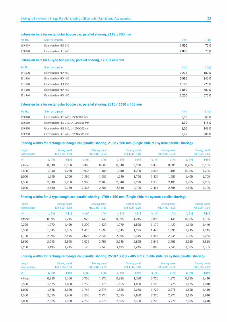
Extension bars for rectangular boogie car, parallel shoring, 2112 x 260 mm
G [kg]l [m]Short descriptionArt. No.
70,01,500Extension bar HEB 240159 575
78,02,000Extension bar HEB 240159 690
Extension bars for U-type boogie car, parallel shoring, 1700 x 450 mm
G [kg]l [m]Short descriptionArt. No.
107,00,275Extension bar HEA 450831 500
140,00,550Extension bar HEA 450831 510
220,01,100Extension bar HEA 450831 520
300,01,650Extension bar HEA 450831 530
375,02,200Extension bar HEA 450831 540
Extension bars for rectangular boogie car, parallel shoring, 2510 / 3310 x 405 mm
G [kg]l [m]Short descriptionArt. No.
65,00,50Extension bar HEB 240, L=500x305 mm159 820
115,01,00Extension bar HEB 240, L=1000x305 mm159 580
148,01,50Extension bar HEB 240, L=1500x305 mm159 660
205,02,00Extension bar HEB 240, L=2000x305 mm159 700
Shoring widths for rectangular boogie car, parallel shoring, 2112 x 260 mm (Single slide rail system parallel shoring)
Shoring panel
KR 6,00 - 7,00
Shoring panel
KRU 4,00 - 5,00
Shoring panel
KRI 4,00 - 5,00
Shoring panel
KRU 2,00 - 3,50
Shoring panel
KRI 2,00 - 3,50
Length
extension bar
b [m]bc [m]b [m]bc [m]b [m]bc [m]b [m]bc [m]b [m]bc [m][m]
0,7050,4050,6850,4350,7900,5400,6850,4650,7600,540without
1,2050,9051,1850,9351,2901,0401,1850,9651,2601,0400,500
1,7051,4051,6851,4351,7901,5401,6851,4651,7601,5401,000
2,2051,9052,1851,9352,2902,0402,1851,9652,2602,0401,500
2,7052,4052,6852,4352,7902,5402,6852,4652,7602,5402,000
Shoring widths for U-type boogie car, parallel shoring, 1700 x 450 mm (Single slide rail system parallel shoring)
Shoring panel
KR 6,00 - 7,00
Shoring panel
KRU 4,00 - 5,00
Shoring panel
KRI 4,00 - 5,00
Shoring panel
KRU 2,00 - 3,50
Shoring panel
KRI 2,00 - 3,50
Legnth
extension bar
b [m]bc [m]b [m]bc [m]b [m]bc [m]b [m]bc [m]b [m]bc [m][m]
1,1650,8651,1450,8951,2450,9951,1450,9251,2150,995without
1,4401,1401,4201,1701,5201,2701,4201,2001,4901,2700,275
1,7151,4151,6951,4451,7951,5451,6951,4751,7651,5450,550
2,2651,9652,2451,9952,3452,0952,2452,0252,3152,0951,100
2,8152,5152,7952,5452,8952,6452,7952,5752,8652,6451,650
3,3653,0653,3453,0953,4453,1953,3453,1253,4153,1952,200
Shoring widths for rectangular boogie car, parallel shoring, 2510 / 3310 x 405 mm (Double slide rail system parallel shoring)
Shoring panel
KR 6,00 - 7,00
Shoring panel
KRU 4,00 - 5,00
Shoring panel
KRI 4,00 - 5,00
Shoring panel
KRU 2,00 - 3,50
Shoring panel
KRI 2,00 - 3,50
Length
extension bar
b [m]bc [m]b [m]bc [m]b [m]bc [m]b [m]bc [m]b [m]bc [m][m]
1,4100,6951,2750,7251,3800,8251,2750,7551,3500,825without
1,9101,1951,7751,2251,8801,3251,7751,2551,8501,3250,500
2,4101,6952,2751,7252,3801,8252,2751,7552,3501,8251,000
2,9102,1952,7752,2252,8802,3252,7752,2552,8502,3251,500
3,4102,6953,2752,7253,3802,8253,2752,7553,3502,8252,000
33Sliding rail systems / krings Parallel shoring / Slide rails, Panels and Accessories
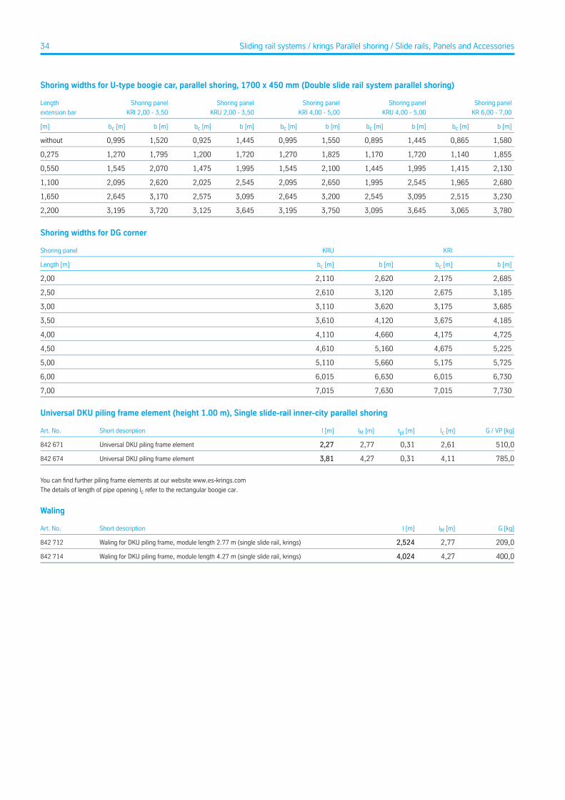
Shoring widths for U-type boogie car, parallel shoring, 1700 x 450 mm (Double slide rail system parallel shoring)
Shoring panel
KR 6,00 - 7,00
Shoring panel
KRU 4,00 - 5,00
Shoring panel
KRI 4,00 - 5,00
Shoring panel
KRU 2,00 - 3,50
Shoring panel
KRI 2,00 - 3,50
Length
extension bar
b [m]bc [m]b [m]bc [m]b [m]bc [m]b [m]bc [m]b [m]bc [m][m]
1,5800,8651,4450,8951,5500,9951,4450,9251,5200,995without
1,8551,1401,7201,1701,8251,2701,7201,2001,7951,2700,275
2,1301,4151,9951,4452,1001,5451,9951,4752,0701,5450,550
2,6801,9652,5451,9952,6502,0952,5452,0252,6202,0951,100
3,2302,5153,0952,5453,2002,6453,0952,5753,1702,6451,650
3,7803,0653,6453,0953,7503,1953,6453,1253,7203,1952,200
Shoring widths for DG corner
KRIKRUShoring panel
b [m]bc [m]b [m]bc [m]Length [m]
2,6852,1752,6202,1102,00
3,1852,6753,1202,6102,50
3,6853,1753,6203,1103,00
4,1853,6754,1203,6103,50
4,7254,1754,6604,1104,00
5,2254,6755,1604,6104,50
5,7255,1755,6605,1105,00
6,7306,0156,6306,0156,00
7,7307,0157,6307,0157,00
Universal DKU piling frame element (height 1.00 m), Single slide-rail inner-city parallel shoring
G / VP [kg]lc [m]tpl [m]lM [m]l [m]Short descriptionArt. No.
510,02,610,312,772,27Universal DKU piling frame element842 671
785,04,110,314,273,81Universal DKU piling frame element842 674
You can find further piling frame elements at our website www.es-krings.com
The details of length of pipe opening lc refer to the rectangular boogie car.
Waling
G [kg]lM [m]l [m]Short descriptionArt. No.
209,02,772,524Waling for DKU piling frame, module length 2.77 m (single slide rail, krings)842 712
400,04,274,024Waling for DKU piling frame, module length 4.27 m (single slide rail, krings)842 714
34 Sliding rail systems / krings Parallel shoring / Slide rails, Panels and Accessories
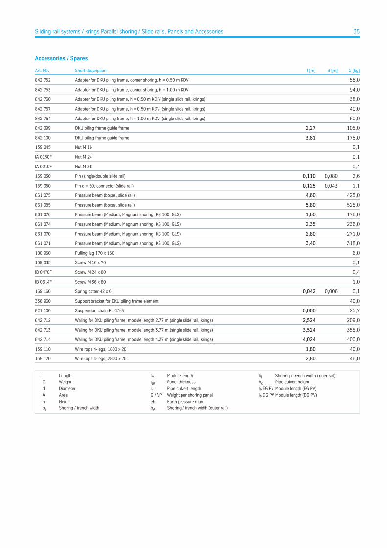
Accessories / Spares
G [kg]d [m]l [m]Short descriptionArt. No.
55,0Adapter for DKU piling frame, corner shoring, h = 0.50 m KDVI842 752
94,0Adapter for DKU piling frame, corner shoring, h = 1.00 m KDVI842 753
38,0Adapter for DKU piling frame, h = 0.50 m KDIV (single slide rail, krings)842 760
40,0Adapter for DKU piling frame, h = 0.50 m KDVI (single slide rail, krings)842 757
60,0Adapter for DKU piling frame, h = 1.00 m KDVI (single slide rail, krings)842 754
105,02,27DKU piling frame guide frame842 099
175,03,81DKU piling frame guide frame842 100
0,1Nut M 16139 045
0,1Nut M 24IA 0150F
0,4Nut M 36IA 0210F
2,60,0800,110Pin (single/double slide rail)159 030
1,10,0430,125Pin d = 50, connector (slide rail)159 050
425,04,60Pressure beam (boxes, slide rail)861 075
525,05,80Pressure beam (boxes, slide rail)861 085
176,01,60Pressure beam (Medium, Magnum shoring, KS 100, GLS)861 076
236,02,35Pressure beam (Medium, Magnum shoring, KS 100, GLS)861 074
271,02,80Pressure beam (Medium, Magnum shoring, KS 100, GLS)861 070
318,03,40Pressure beam (Medium, Magnum shoring, KS 100, GLS)861 071
6,0Pulling lug 170 x 150100 950
0,1Screw M 16 x 70139 035
0,4Screw M 24 x 80IB 0470F
1,0Screw M 36 x 80IB 0614F
0,10,0060,042Spring cotter 42 x 6159 160
40,0Support bracket for DKU piling frame element336 960
25,75,000Suspension chain KL-13-8821 100
209,02,524Waling for DKU piling frame, module length 2.77 m (single slide rail, krings)842 712
355,03,524Waling for DKU piling frame, module length 3.77 m (single slide rail, krings)842 713
400,04,024Waling for DKU piling frame, module length 4.27 m (single slide rail, krings)842 714
40,01,80Wire rope 4-legs, 1800 x 20139 110
46,02,80Wire rope 4-legs, 2800 x 20139 120
Shoring / trench width (inner rail)bIModule lengthlMLengthl
Pipe culvert heighthcPanel thicknesstplWeightG
Module length (EG PV)lMEG PVPipe culvert lengthlcDiameterd
Module length (DG PV)lMDG PVWeight per shoring panelG / VPAreaA
Earth pressure max.ehHeighth
Shoring / trench width (outer rail)bAShoring / trench widthbc
35Sliding rail systems / krings Parallel shoring / Slide rails, Panels and Accessories

Trench Box Systems
e+s Trench boxesOverview of depths
1 m
2 m
4 m
3 m
reco
mm
ende
d sh
orin
g de
pth
reco
mm
ende
d sh
orin
g de
pth
1 m
6 m
5 m
2 m
4 m
3 m
DragboxPage 51
Lightweight-BoxesPage 37
Medium-BoxesPage 40
Manhole-BoxesPage 49
Linear-BoxesPage 47
Magnum-Boxes 3,15Page 44
Magnum-Boxes 3,15Page 44
Magnum-Boxes 4,00Page 44
36
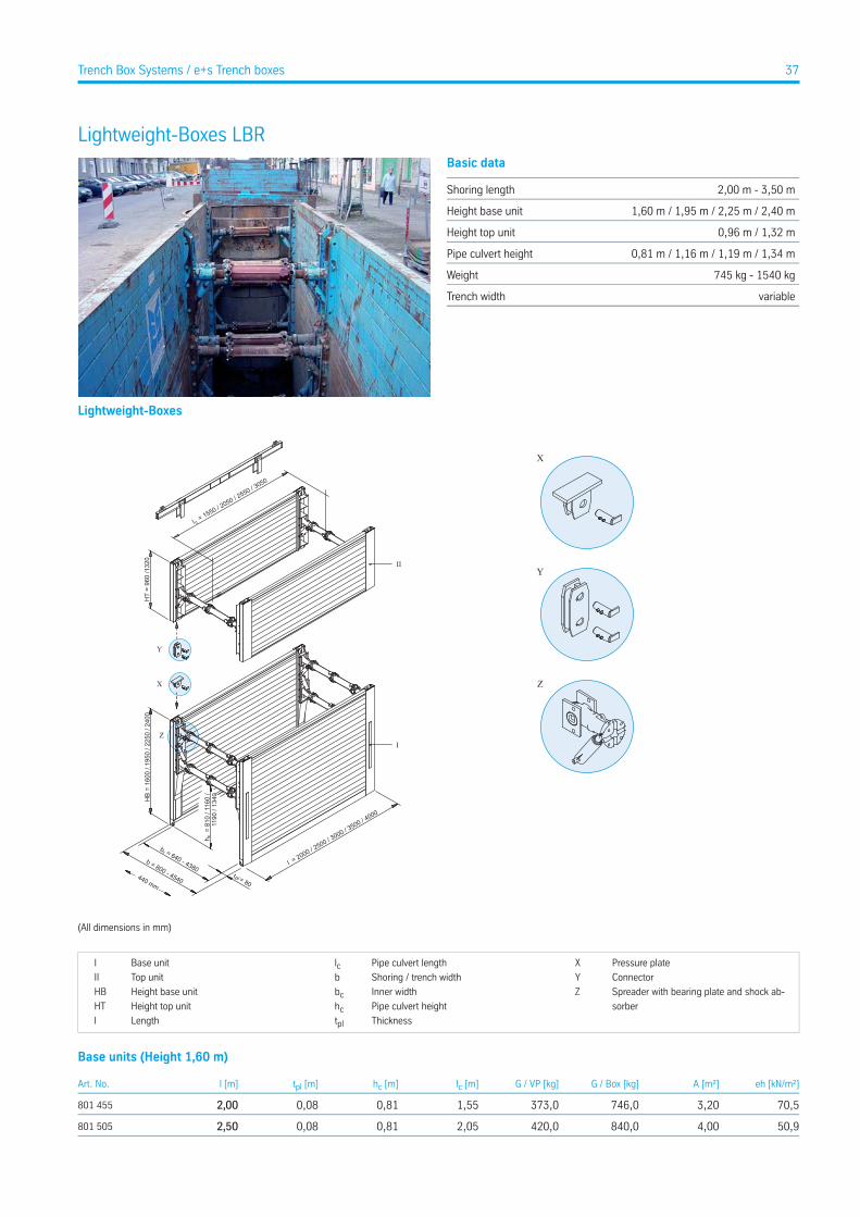
Lightweight-Boxes LBRBasic data
2,00 m - 3,50 mShoring length
1,60 m / 1,95 m / 2,25 m / 2,40 mHeight base unit
0,96 m / 1,32 mHeight top unit
0,81 m / 1,16 m / 1,19 m / 1,34 mPipe culvert height
745 kg - 1540 kgWeight
variableTrench width
Lightweight-Boxes
X
Y
ZX
Y
Z
l = 2000 / 2500 / 3
000 / 3500 / 4
000
t = 80pl
b = 640 - 4380b = 800 - 4540
HT
= 96
0 /1
320
cl = 1550 / 2
050 / 2550 / 3
050
HB
= 16
00 /
1950
/ 22
50 /
2400
h =
810
/ 11
60 /
119
0 / 1
340
c
II
I
c
440 mm
(All dimensions in mm)
Pressure plateXPipe culvert lengthlcBase unitI
ConnectorYShoring / trench widthbTop unitII
Spreader with bearing plate and shock ab-
sorber
ZInner widthbcHeight base unitHB
Pipe culvert heighthcHeight top unitHT
ThicknesstplLengthl
Base units (Height 1,60 m)
eh [kN/m²]A [m²]G / Box [kg]G / VP [kg]lc [m]hc [m]tpl [m]l [m]Art. No.
70,53,20746,0373,01,550,810,082,00801 455
50,94,00840,0420,02,050,810,082,50801 505
37Trench Box Systems / e+s Trench boxes

Base units (Height 1,60 m)
eh [kN/m²]A [m²]G / Box [kg]G / VP [kg]lc [m]hc [m]tpl [m]l [m]Art. No.
34,04,801.004,0502,02,550,810,083,00801 568
24,35,601.076,0538,03,050,810,083,50801 578
Base units (Height 1,95 m)
eh [kN/m²]A [m²]G / Box [kg]G / VP [kg]lc [m]hc [m]tpl [m]l [m]Art. No.
58,33,90846,0423,01,551,160,082,00801 475
46,64,88956,0478,02,051,160,082,50801 525
34,05,851.096,0548,02,551,160,083,00801 565
24,36,831.236,0618,03,051,160,083,50801 575
18,67,801.596,0798,03,551,190,084,00801 590 *
Base units (Height 2,25 m)
eh [kN/m²]A [m²]G / Box [kg]G / VP [kg]lc [m]hc [m]tpl [m]l [m]Art. No.
61,14,501.030,0515,01,551,190,082,00801 015
48,95,631.190,0595,02,051,190,082,50801 055
34,06,751.340,0670,02,551,190,083,00801 105
24,37,881.480,0740,03,051,190,083,50801 108
18,69,001920,0960,03,551,190,084,00801 109 *
Base units (Height 2,40 m)
eh [kN/m²]A [m²]G / Box [kg]G / VP [kg]lc [m]hc [m]tpl [m]l [m]Art. No.
50,64,801.100,0550,01,551,340,082,00801 210
40,56,001.270,0635,02,051,340,082,50801 215
34,07,201.350,0675,02,551,340,083,00801 220
24,38,401.540,0770,03,051,340,083,50801 110
18,69,601960,0980,03,551,340,084,00801 115 *
Top units (Height 0,96 m)
eh [kN/m²]A [m²]G / Box [kg]G / VP [kg]lc [m]hc [m]tpl [m]l [m]Art. No.
70,51,92556,0278,01,55-0,082,00801 595
50,92,40634,0317,02,05-0,082,50801 625
34,02,88714,0357,02,55-0,083,00801 665
24,33,36790,0395,03,05-0,083,50801 675
18,63,84930,0465,03,55-0,084,00801 676 *
Top units (Height 1,32 m)
eh [kN/m²]A [m²]G / Box [kg]G / VP [kg]lc [m]hc [m]tpl [m]l [m]Art. No.
70,52,64682,0341,01,55-0,082,00801 628
50,93,30782,0391,02,05-0,082,50801 630
34,03,96816,0408,02,55-0,083,00801 635
24,34,62860,0430,03,05-0,083,50801 680
18,65,281.146,0573,03,55-0,084,00801 678 *
* for sale at customer’s request
Extension bars
G [kg]l [m]Short descriptionArt. No.
11,20,250Extension bar GGG 50850 091
18,70,550Extension bar GGG 50850 100
38 Trench Box Systems / e+s Trench boxes / Lightweight-Boxes LBR
Extension bars
G [kg]l [m]Short descriptionArt. No.
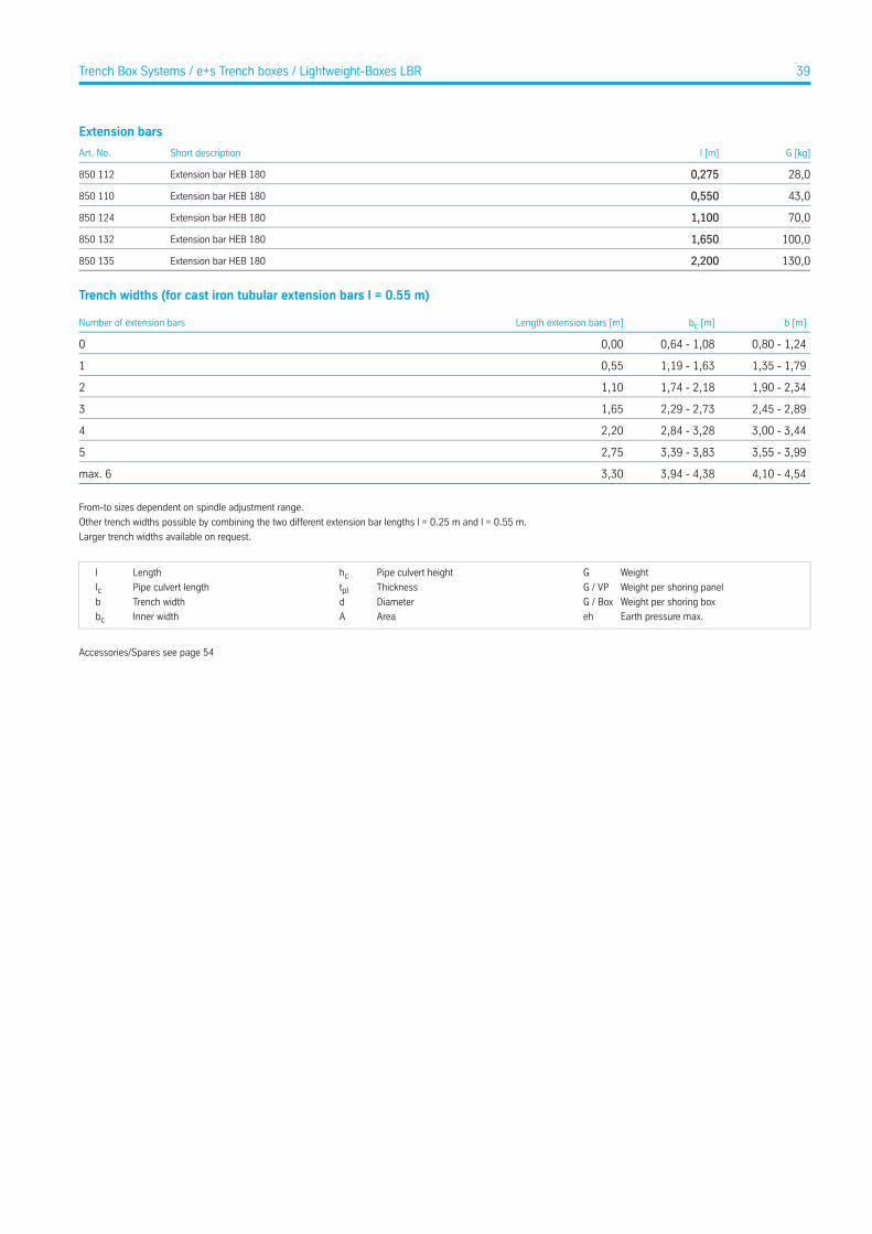
28,00,275Extension bar HEB 180850 112
43,00,550Extension bar HEB 180850 110
70,01,100Extension bar HEB 180850 124
100,01,650Extension bar HEB 180850 132
130,02,200Extension bar HEB 180850 135
Trench widths (for cast iron tubular extension bars l = 0.55 m)
b [m]bc [m]Length extension bars [m]Number of extension bars
0,80 - 1,240,64 - 1,080,000
1,35 - 1,791,19 - 1,630,551
1,90 - 2,341,74 - 2,181,102
2,45 - 2,892,29 - 2,731,653
3,00 - 3,442,84 - 3,282,204
3,55 - 3,993,39 - 3,832,755
4,10 - 4,543,94 - 4,383,30max. 6
From-to sizes dependent on spindle adjustment range.
Other trench widths possible by combining the two different extension bar lengths l = 0.25 m and l = 0.55 m.
Larger trench widths available on request.
WeightGPipe culvert heighthcLengthl
Weight per shoring panelG / VPThicknesstplPipe culvert lengthlcWeight per shoring boxG / BoxDiameterdTrench widthb
Earth pressure max.ehAreaAInner widthbc
Accessories/Spares see page 54
39Trench Box Systems / e+s Trench boxes / Lightweight-Boxes LBR
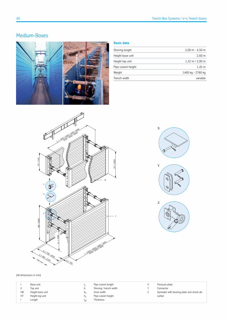
Medium-BoxesBasic data
2,00 m - 4,50 mShoring length
2,60 mHeight base unit
1,32 m / 2,00 mHeight top unit
1,45 mPipe culvert height
1460 kg - 2780 kgWeight
variableTrench width
X
Y
Z
HB
= 26
00
h =
145
0c
l = 2000 / 2500 / 2
900 / 3400
3700 / 4000 / 4
500
cb = 780 - 4520b = 980 - 4720 plt = 100
I
440 mm
HT
= 20
00
II
HT
= 13
20
cl = 1550 / 2
050 / 2450 / 2
950
3250 / 3550 / 4
050
X
Y
Z
(All dimensions in mm)
Pressure plateXPipe culvert lengthlcBase unitI
ConnectorYShoring / trench widthbTop unitII
Spreader with bearing plate and shock ab-
sorber
ZInner widthbcHeight base unitHB
Pipe culvert heighthcHeight top unitHT
ThicknesstplLengthl
40 Trench Box Systems / e+s Trench boxes

Base units (Height 2,60 m)
eh [kN/m²]A [m²]G / Box [kg]G / VP [kg]lc [m]hc [m]tpl [m]l [m]Art. No.
70,05,201.460,0730,01,551,460,102,00800 010
60,06,501.650,0825,02,051,460,102,50800 100
55,07,541.816,0908,02,451,460,102,90800 150
50,88,842.056,01.028,02,951,460,103,40800 200
42,39,622.236,01.118,03,251,460,103,70800 300
44,010,402.514,01.257,03,551,460,104,00800 400
34,211,702.780,01.390,04,051,460,104,50800 440 *
Top units (Height 1,32 m)
eh [kN/m²]A [m²]G / Box [kg]G / VP [kg]lc [m]hc [m]tpl [m]l [m]Art. No.
165,02,64926,0463,01,55-0,102,00800 550
99,33,301.062,0531,02,05-0,102,50800 600
71,53,831.156,0578,02,45-0,102,90800 650
50,54,491.316,0658,02,95-0,103,40800 700
42,14,881.384,0692,03,25-0,103,70800 800
43,85,281.550,0775,03,55-0,104,00800 900
34,25,941.640,0820,04,05-0,104,50800 950 *
Top units (Height 2,00 m)
eh [kN/m²]A [m²]G / Box [kg]G / VP [kg]lc [m]hc [m]tpl [m]l [m]Art. No.
165,04,001.394,0697,01,55-0,102,00802 680
99,35,001.570,0785,02,05-0,102,50802 690
71,55,801.680,0840,02,45-0,102,90802 550
50,56,801.860,0930,02,95-0,103,40802 700
42,17,401980,0990,03,25-0,103,70802 750
43,88,002.170,01.085,03,55-0,104,00802 751 *
34,29,002.384,01.192,04,05-0,104,50800 951 *
* for sale at customer’s request
Extension bars
G [kg]l [m]Short descriptionArt. No.
11,20,250Extension bar GGG 50850 091
18,70,550Extension bar GGG 50850 100
28,00,275Extension bar HEB 180850 112
43,00,550Extension bar HEB 180850 110
70,01,100Extension bar HEB 180850 124
100,01,650Extension bar HEB 180850 132
130,02,200Extension bar HEB 180850 135
41Trench Box Systems / e+s Trench boxes / Medium-Boxes
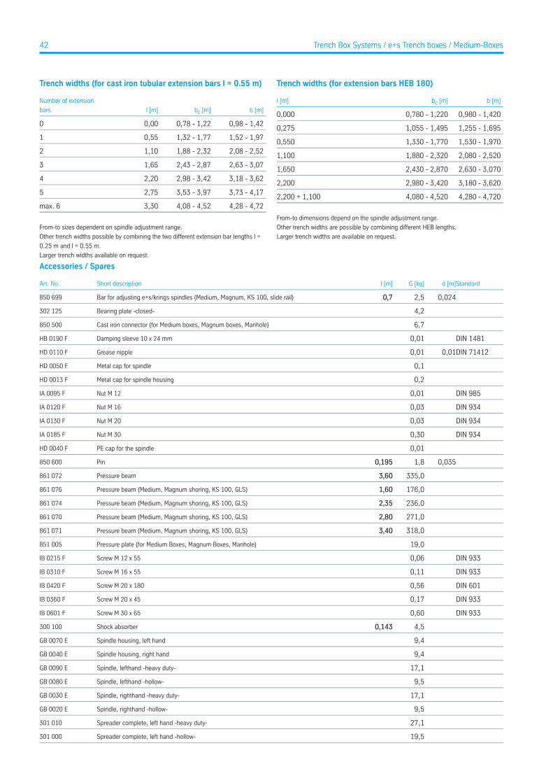
Trench widths (for cast iron tubular extension bars l = 0.55 m)
b [m]bc [m]l [m]
Number of extension
bars
0,98 - 1,420,78 - 1,220,000
1,52 - 1,971,32 - 1,770,551
2,08 - 2,521,88 - 2,321,102
2,63 - 3,072,43 - 2,871,653
3,18 - 3,622,98 - 3,422,204
3,73 - 4,173,53 - 3,972,755
4,28 - 4,724,08 - 4,523,30max. 6
From-to sizes dependent on spindle adjustment range.
Other trench widths possible by combining the two different extension bar lengths l =
0.25 m and l = 0.55 m.
Larger trench widths available on request.
Trench widths (for extension bars HEB 180)
b [m]bc [m]l [m]
0,980 - 1,4200,780 - 1,2200,000
1,255 - 1,6951,055 - 1,4950,275
1,530 - 1,9701,330 - 1,7700,550
2,080 - 2,5201,880 - 2,3201,100
2,630 - 3,0702,430 - 2,8701,650
3,180 - 3,6202,980 - 3,4202,200
4,280 - 4,7204,080 - 4,5202,200 + 1,100
From-to dimensions depend on the spindle adjustment range.
Other trench widths are possible by combining different HEB lengths.
Larger trench widths are available on request.
Accessories / Spares
Standardd [m]G [kg]l [m]Short descriptionArt. No.
0,0242,50,7Bar for adjusting e+s/krings spindles (Medium, Magnum, KS 100, slide rail)850 699
4,2Bearing plate -closed-302 125
6,7Cast iron connector (for Medium boxes, Magnum boxes, Manhole)850 500
DIN 14810,01Damping sleeve 10 x 24 mmHB 0190 F
DIN 714120,010,01Grease nippleHD 0110 F
0,1Metal cap for spindleHD 0050 F
0,2Metal cap for spindle housingHD 0013 F
DIN 9850,01Nut M 12IA 0095 F
DIN 9340,03Nut M 16IA 0120 F
DIN 9340,03Nut M 20IA 0130 F
DIN 9340,30Nut M 30IA 0185 F
0,01PE cap for the spindleHD 0040 F
0,0351,80,195Pin850 600
335,03,60Pressure beam861 072
176,01,60Pressure beam (Medium, Magnum shoring, KS 100, GLS)861 076
236,02,35Pressure beam (Medium, Magnum shoring, KS 100, GLS)861 074
271,02,80Pressure beam (Medium, Magnum shoring, KS 100, GLS)861 070
318,03,40Pressure beam (Medium, Magnum shoring, KS 100, GLS)861 071
19,0Pressure plate (for Medium Boxes, Magnum Boxes, Manhole)851 005
DIN 9330,06Screw M 12 x 55IB 0215 F
DIN 9330,11Screw M 16 x 55IB 0310 F
DIN 6010,56Screw M 20 x 180IB 0420 F
DIN 9330,17Screw M 20 x 45IB 0360 F
DIN 9330,60Screw M 30 x 65IB 0601 F
4,50,143Shock absorber300 100
9,4Spindle housing, left handGB 0070 E
9,4Spindle housing, right handGB 0040 E
17,1Spindle, lefthand -heavy duty-GB 0090 E
9,5Spindle, lefthand -hollow-GB 0080 E
17,1Spindle, righthand -heavy duty-GB 0030 E
9,5Spindle, righthand -hollow-GB 0020 E
27,1Spreader complete, left hand -heavy duty-301 010
19,5Spreader complete, left hand -hollow-301 000
42 Trench Box Systems / e+s Trench boxes / Medium-Boxes
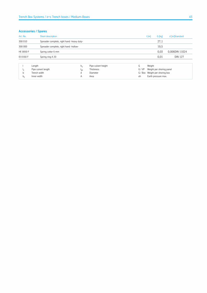
Accessories / Spares
Standardd [m]G [kg]l [m]Short descriptionArt. No.
27,1Spreader complete, right hand -heavy duty-300 010
19,5Spreader complete, right hand -hollow-300 000
DIN 110240,0060,03Spring cotter 6 mmHE 0050 F
DIN 1270,01Spring ring A 20ID 0160 F
WeightGPipe culvert heighthcLengthl
Weight per shoring panelG / VPThicknesstplPipe culvert lengthlcWeight per shoring boxG / BoxDiameterdTrench widthb
Earth pressure max.ehAreaAInner widthbc
43Trench Box Systems / e+s Trench boxes / Medium-Boxes
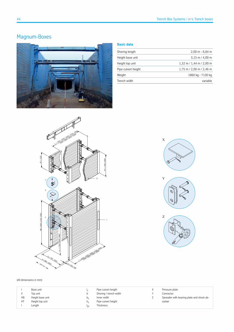
Magnum-BoxesBasic data
2,00 m - 6,84 mShoring length
3,15 m / 4,00 mHeight base unit
1,32 m / 1,44 m / 2,00 mHeight top unit
1,75 m / 2,00 m / 2,46 mPipe culvert height
1860 kg - 7130 kgWeight
variableTrench width
X
Y
Z
X
Y
Z
HB
= 30
00 /
3150
/ 40
00
h =
175
0 / 2
000
/ 246
0c
l = 2000 / 2500 / 2
900 / 3150 / 3
400
3700 / 4000 / 5
080 / 6840
t = 100 / 160
pl
b = 780 - 4620
c
b = 980 - 4840
I
440 mm
l = 1550 / 2
050 / 2450 / 2
700 / 2950
c 3250 / 3550 / 4
630 / 6380
HT
= 13
20
HT
= 14
40 /
2000
II
(All dimensions in mm)
Pressure plateXPipe culvert lengthlcBase unitI
ConnectorYShoring / trench widthbTop unitII
Spreader with bearing plate and shock ab-
sorber
ZInner widthbcHeight base unitHB
Pipe culvert heighthcHeight top unitHT
ThicknesstplLengthl
44 Trench Box Systems / e+s Trench boxes

Base units (Height 3,00 m)
eh [kN/m²]A [m²]G / Box [kg]G / VP [kg]lc [m]hc [m]tpl [m]l [m]Art. No.
69,56,301.730,0865,01,552,010,102,00802 035
55,77,501.940,0970,02,052,010,102,50802 042
48,08,702.120,01.060,02,452,010,102,90802 045
41,010,202.330,01.165,02,952,010,103,40802 120
37,711,102.460,01.230,03,252,010,103,70802 205
35,812,002.780,01.390,03,552,010,104,00802 285 A
28,615,243.372,01.686,04,632,010,125,08802 400
25,821,557.130,03.565,06,381,750,166,84802 460
Base units (Height 3,15 m)
eh [kN/m²]A [m²]G / Box [kg]G / VP [kg]lc [m]hc [m]tpl [m]l [m]Art. No.
73,16,301.860,0930,01,552,010,102,00802 036
58,57,502.084,01.042,02,052,010,102,50802 040
50,48,702.276,01.138,02,452,010,102,90802 050
43,010,202.520,01.260,02,952,010,103,40802 175
39,511,102.856,01.428,03,252,010,103,70802 210
36,512,003.158,01.579,03,552,010,104,00802 300
28,615,243.836,01.918,04,632,010,125,08802 425
25,0821,557.130,03.565,06,381,750,166,84802 460
Base units (Height 4,00 m)
eh [kN/m²]A [m²]G / Box [kg]G / VP [kg]lc [m]hc [m]tpl [m]l [m]Art. No.
46,012,602.770,01.385,02,702,460,083,15802 100
41,013,603.136,01.568,02,952,460,093,40802 197 A
Top units (Height 1,32 m)
eh [kN/m²]A [m²]G / Box [kg]G / VP [kg]lc [m]hc [m]tpl [m]l [m]Art. No.
165,02,64926,0463,01,55-0,102,00800 550
99,33,301.062,0531,02,05-0,102,50800 600
71,53,831.156,0578,02,45-0,102,90800 650
60,74,161.340,0670,02,70-0,083,15802 560
50,54,491.316,0658,02,95-0,103,40800 700
42,14,881.384,0692,03,25-0,103,70800 800
43,85,281.550,0775,03,55-0,104,00800 900
34,26,712.220,01.110,04,63-0,125,08802 814
Top units (Height 1,44 m)
eh [kN/m²]A [m²]G / Box [kg]G / VP [kg]lc [m]hc [m]tpl [m]l [m]Art. No.
25,89,853.010,01.505,06,38-0,166,84802 815
Top units (Height 2,00 m)
eh [kN/m²]A [m²]G / Box [kg]G / VP [kg]lc [m]hc [m]tpl [m]l [m]Art. No.
165,04,001.394,0697,01,55-0,102,00802 680
99,35,001.570,0785,02,05-0,102,50802 690
71,55,801.680,0840,02,45-0,102,90802 550
60,76,301.720,0860,02,70-0,083,15802 600 *
50,56,801.860,0930,02,95-0,103,40802 700
45Trench Box Systems / e+s Trench boxes / Magnum-Boxes
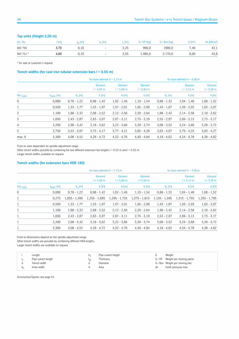
Top units (Height 2,00 m)
eh [kN/m²]A [m²]G / Box [kg]G / VP [kg]lc [m]hc [m]tpl [m]l [m]Art. No.
42,17,401980,0990,03,25-0,103,70802 750
43,88,002.170,01.085,03,55-0,104,00802 751 *
* for sale at customer’s request
Trench widths (for cast iron tubular extension bars l = 0.55 m)
for base element h = 4,00 mfor base element h = 3,15 m
Element
l = 3,40 m
Element
l = 3,15 m
Element
l = 6,84 m
Element
l = 5,08 m
Element
l = 4,00 m
b [m]b [m]bc [m]b [m]b [m]b [m]bc [m]lZwSt. [m]Anz.ZwSt.
1,08 - 1,521,04 - 1,480,88 - 1.321,10 - 1,541,02 - 1,460,98 - 1,420,78 - 1,220,0000
1,63 - 2,071,59 - 2,031,43 - 1,871,65 - 2,091,57 - 2,011,53 - 1,971,33 - 1,770,5501
2,18 - 2,622,14 - 2,581,98 - 2,422,20 - 2,642,12 - 2,562,08 - 2,521,88 - 2,321,1002
2,73 - 3,172,69 - 3,132,53 - 2,972,75 - 3,192,67 - 3,112,63 - 3,072,43 - 2,871,6503
3,28 - 3,723,24 - 3,683,08 - 3,523,30 - 3,743,22 - 3,663,18 - 3,622,98 - 3,422,2004
3,83 - 4,273,79 - 4,233,63 - 4,073,85 - 4,293,77 - 4,213,73 - 4,173,53 - 3,972,7505
4,38 - 4,824,34 - 4,784,18 - 4,624,40 - 4,844,32 - 4,764,28 - 4,724,08 - 4,523,300max. 6
From-to sizes dependent on spindle adjustment range.
Other trench widths possible by combining the two different extension bar lengths l = 0.25 m and l = 0.55 m.
Larger trench widths available on request.
Trench widths (for extension bars HEB 180)
for base element h = 4.00 mfor base element h = 3.15 m
Element
l = 3.40 m
Element
l = 3.15 m
Element
l = 6.84 m
Element
l = 5,08 m
Element
l = 4.00 m
b [m]b [m]bc [m]b [m]b [m]b [m]bc [m]lZwSt. [m]Anz.ZwSt.
1,08 - 1,521,04 - 1,480,88 - 1.321,10 - 1,541,02 - 1,460,98 - 1,420,78 - 1,220,0000
1,355 - 1,7951,315 - 1,7551,155 - 1,5951,375 - 1,8151,295 - 1,7351,255 - 1,6951,055 - 1,4950,2751
1,63 - 2,071,59 - 2,031,43 - 1,871,65 - 2,091,57 - 2,011,53 - 1,971,33 - 1,770,5501
2,18 - 2,622,14 - 2,581,98 - 2,422,20 - 2,642,12 - 2,562,08 - 2,521,88 - 2,321,1001
2,73 - 3,172,69 - 3,132,53 - 2,972,75 - 3,192,67 - 3,112,63 - 3,072,43 - 2,871,6501
3,28 - 3,723,24 - 3,683,08 - 3,523,30 - 3,743,22 - 3,663,18 - 3,622,98 - 3,422,2001
4,38 - 4,824,34 - 4,784,18 - 4,624,40 - 4,844,32 - 4,764,28 - 4,724,08 - 4,523,3001
From-to dimensions depend on the spindle adjustment range.
Other trench widths are possible by combining different HEB lengths.
Larger trench widths are available on request.
WeightGPipe culvert heighthcLengthl
Weight per shoring panelG / VPThicknesstplPipe culvert lengthlcWeight per shoring boxG / BoxDiameterdTrench widthb
Earth pressure max.ehAreaAInner widthbc
Accessories/Spares see page 54
46 Trench Box Systems / e+s Trench boxes / Magnum-Boxes
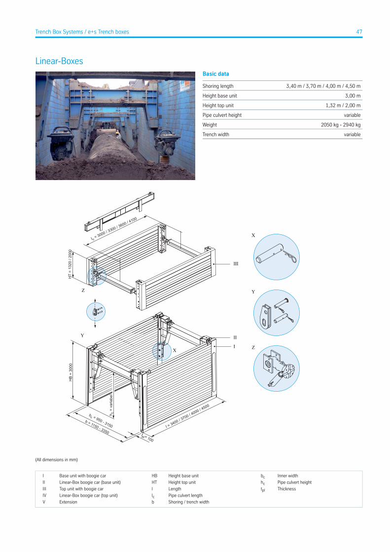
Linear-BoxesBasic data
3,40 m / 3,70 m / 4,00 m / 4,50 mShoring length
3,00 mHeight base unit
1,32 m / 2,00 mHeight top unit
variablePipe culvert height
2050 kg - 2940 kgWeight
variableTrench width
X
Y
Z
HB
= 30
00
III
HT
= 13
20 /
2000
I c = 3000 / 3300 / 3600 / 4100
X
b = 1150 - 3350
bc = 950 - 3150
tpl = 100
h c =
var
iabe
l
I = 3400 / 3700 / 4000 / 4500
Z
Y
I
II
(All dimensions in mm)
Inner widthbcHeight base unitHBBase unit with boogie carI
Pipe culvert heighthcHeight top unitHTLinear-Box boogie car (base unit)II
ThicknesstplLengthlTop unit with boogie carIII
Pipe culvert lengthlcLinear-Box boogie car (top unit)IV
Shoring / trench widthbExtensionV
47Trench Box Systems / e+s Trench boxes
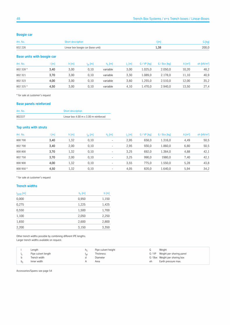
Boogie car
G [kg]l [m]Short descriptionArt. No.
200,01,38Linear box boogie car (base unit)832 226
Base units with boogie car
eh [kN/m²]A [m²]G / Box [kg]G / VP [kg]lc [m]hc [m]tpl [m]h [m]l [m]Art. No.
48,210,202.050,01.025,03,00variable0,103,003,40802 328 *
40,911,102.178,01.089,03,30variable0,103,003,70802 321
35,212,002.510,01.255,03,60variable0,103,004,00802 323
27,413,502.940,01.470,04,10variable0,103,004,50802 325 *
* for sale at customer’s request
Base panels reinforced
Short descriptionArt. No.
Linear box 4.00 m x 3.00 m reinforced802337
Top units with struts
eh [kN/m²]A [m²]G / Box [kg]G / VP [kg]lc [m]hc [m]tpl [m]h [m]l [m]Art. No.
50,54,491.316,0658,02,95-0,101,323,40800 700
50,56,801.860,0930,02,95-0,102,003,40802 700
42,14,881.384,0692,03,25-0,101,323,70800 800
42,17,401980,0990,03,25-0,102,003,70802 750
43,85,281.550,0775,03,55-0,101,324,00800 900
34,25,941.640,0820,04,05-0,101,324,50800 950 *
* for sale at customer’s request
Trench widths
b [m]bc [m]lZwSt [m]
1,1500,9500,000
1,4251,2250,275
1,7001,5000,550
2,2502,0501,100
2,8002,6001,650
3,3503,1502,200
Other trench widths possible by combining different IPE lengths.
Larger trench widths available on request.
WeightGPipe culvert heighthcLengthl
Weight per shoring panelG / VPThicknesstplPipe culvert lengthlcWeight per shoring boxG / BoxDiameterdTrench widthb
Earth pressure max.ehAreaAInner widthbc
Accessories/Spares see page 54
48 Trench Box Systems / e+s Trench boxes / Linear-Boxes
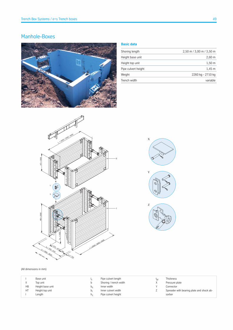
Manhole-BoxesBasic data
2,50 m / 3,00 m / 3,50 mShoring length
2,60 mHeight base unit
1,50 mHeight top unit
1,45 mPipe culvert height
2260 kg - 2710 kgWeight
variableTrench width
X
Y
Z
cl = 2050 / 2
550 / 3050
HT
= 15
00H
B =
2500
t = 100pl
ib = 570 - 4310b = 1890 - 5630
b = 1690 - 5430
c
560
c
h
= 1
450
l = 2500 / 3000 / 3
500
II
I
440 mm
X
Y
Z
(All dimensions in mm)
ThicknesstplPipe culvert lengthlcBase unitI
Pressure plateXShoring / trench widthbTop unitII
ConnectorYInner widthbcHeight base unitHB
Spreader with bearing plate and shock ab-
sorber
ZInner culvert widthbiHeight top unitHT
Pipe culvert heighthcLengthl
49Trench Box Systems / e+s Trench boxes
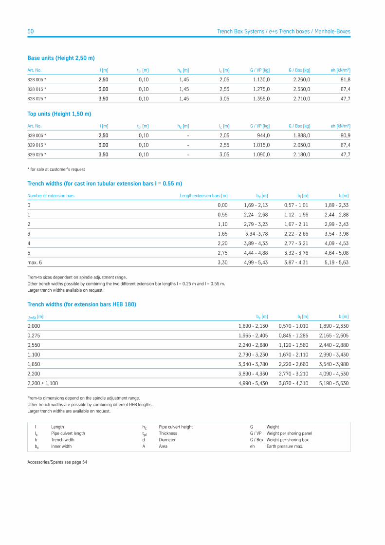
Base units (Height 2,50 m)
eh [kN/m²]G / Box [kg]G / VP [kg]lc [m]hc [m]tpl [m]l [m]Art. No.
81,82.260,01.130,02,051,450,102,50828 005 *
67,42.550,01.275,02,551,450,103,00828 015 *
47,72.710,01.355,03,051,450,103,50828 025 *
Top units (Height 1,50 m)
eh [kN/m²]G / Box [kg]G / VP [kg]lc [m]hc [m]tpl [m]l [m]Art. No.
90,91.888,0944,02,05-0,102,50829 005 *
67,42.030,01.015,02,55-0,103,00829 015 *
47,72.180,01.090,03,05-0,103,50829 025 *
* for sale at customer’s request
Trench widths (for cast iron tubular extension bars l = 0.55 m)
b [m]bi [m]bc [m]Length extension bars [m]Number of extension bars
1,89 - 2,330,57 - 1,011,69 - 2,130,000
2,44 - 2,881,12 - 1,562,24 - 2,680,551
2,99 - 3,431,67 - 2,112,79 - 3,231,102
3,54 - 3,982,22 - 2,663,34 -3,781,653
4,09 - 4,532,77 - 3,213,89 - 4,332,204
4,64 - 5,083,32 - 3,764,44 - 4,882,755
5,19 - 5,633,87 - 4,314,99 - 5,433,30max. 6
From-to sizes dependent on spindle adjustment range.
Other trench widths possible by combining the two different extension bar lengths l = 0.25 m and l = 0.55 m.
Larger trench widths available on request.
Trench widths (for extension bars HEB 180)
b [m]bi [m]bc [m]lZwSt [m]
1,890 - 2,3300,570 - 1,0101,690 - 2,1300,000
2,165 - 2,6050,845 - 1,2851,965 - 2,4050,275
2,440 - 2,8801,120 - 1,5602,240 - 2,6800,550
2,990 - 3,4301,670 - 2,1102,790 - 3,2301,100
3,540 - 3,9802,220 - 2,6603,340 - 3,7801,650
4,090 - 4,5302,770 - 3,2103,890 - 4,3302,200
5,190 - 5,6303,870 - 4,3104,990 - 5,4302,200 + 1,100
From-to dimensions depend on the spindle adjustment range.
Other trench widths are possible by combining different HEB lengths.
Larger trench widths are available on request.
WeightGPipe culvert heighthcLengthl
Weight per shoring panelG / VPThicknesstplPipe culvert lengthlcWeight per shoring boxG / BoxDiameterdTrench widthb
Earth pressure max.ehAreaAInner widthbc
Accessories/Spares see page 54
50 Trench Box Systems / e+s Trench boxes / Manhole-Boxes
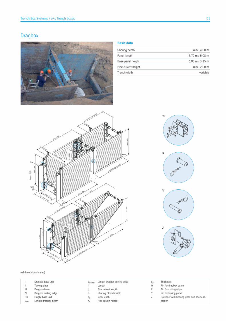
DragboxBasic data
max. 4,00 mShoring depth
3,70 m / 5,08 mPanel length
3,00 m / 3,15 mBase panel height
max. 2,00 mPipe culvert height
variableTrench width
X
Y
Z
W
l = 3700 / 5080 / 6
840
500
IV
III
h =
200
5
c
b = 1200 - 4540
plt =100/120 160
l = 3600 / 4
800 / 6600
c
HB
= 31
50
b = 1000 - 4300
c
LVbr = 950 - 4250
L
=
260
0Sc
huh
I
II
cl = 4680
plt = 150
l = 4760
HB
= 30
00
Y
Z
IV
III
h =
200
5
c
b = 1200 - 4540
plt =100/120
l = 3250 / 4
630
c
II
cl = 2050 / 2
450 / 2950
l = 3700 / 5080
l = 2500 / 2900 / 3
400
I
500
HB
= 31
50
b = 1000 - 4300
c
LVbr = 950 - 4250
HB
= 26
00
plt = 100
L
=
260
0Sc
huh
W
X
W
X
Y
Z
(All dimensions in mm)
ThicknesstplLength dragbox cutting edgeLSchuhDragbox base unitI
Pin for dragbox beamWLengthlTowing plateII
Pin for cutting edgeXPipe culvert lengthlcDragbox-beamIII
Pin for towing panelYShoring / trench widthbDragbox cutting edgeIV
Spreader with bearing plate and shock ab-
sorber
ZInner widthbcHeight base unitHB
Pipe culvert heighthcLength dragbox-beamLVbr
51Trench Box Systems / e+s Trench boxes
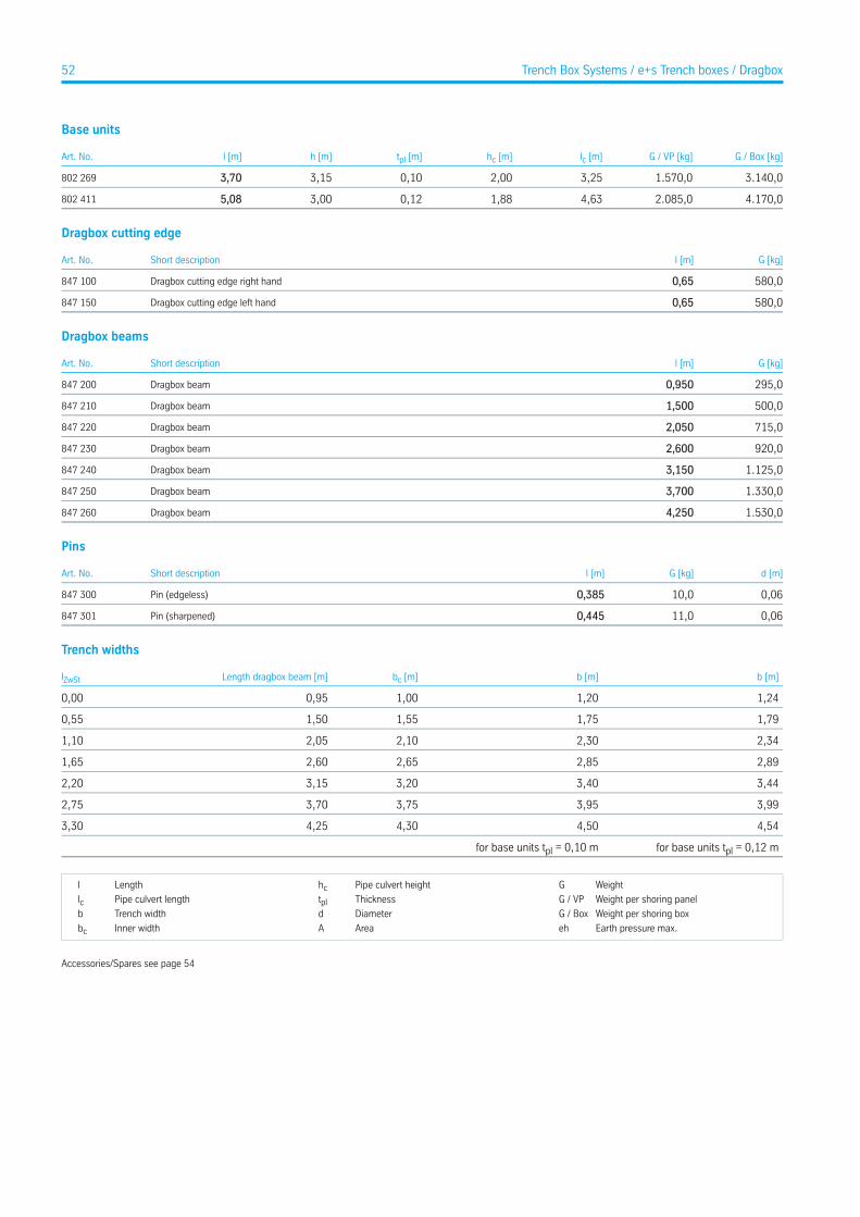
Base units
G / Box [kg]G / VP [kg]lc [m]hc [m]tpl [m]h [m]l [m]Art. No.
3.140,01.570,03,252,000,103,153,70802 269
4.170,02.085,04,631,880,123,005,08802 411
Dragbox cutting edge
G [kg]l [m]Short descriptionArt. No.
580,00,65Dragbox cutting edge right hand847 100
580,00,65Dragbox cutting edge left hand847 150
Dragbox beams
G [kg]l [m]Short descriptionArt. No.
295,00,950Dragbox beam847 200
500,01,500Dragbox beam847 210
715,02,050Dragbox beam847 220
920,02,600Dragbox beam847 230
1.125,03,150Dragbox beam847 240
1.330,03,700Dragbox beam847 250
1.530,04,250Dragbox beam847 260
Pins
d [m]G [kg]l [m]Short descriptionArt. No.
0,0610,00,385Pin (edgeless)847 300
0,0611,00,445Pin (sharpened)847 301
Trench widths
b [m]b [m]bc [m]Length dragbox beam [m]lZwSt
1,241,201,000,950,00
1,791,751,551,500,55
2,342,302,102,051,10
2,892,852,652,601,65
3,443,403,203,152,20
3,993,953,753,702,75
4,544,504,304,253,30
for base units tpl = 0,12 mfor base units tpl = 0,10 m
WeightGPipe culvert heighthcLengthl
Weight per shoring panelG / VPThicknesstplPipe culvert lengthlcWeight per shoring boxG / BoxDiameterdTrench widthb
Earth pressure max.ehAreaAInner widthbc
Accessories/Spares see page 54
52 Trench Box Systems / e+s Trench boxes / Dragbox
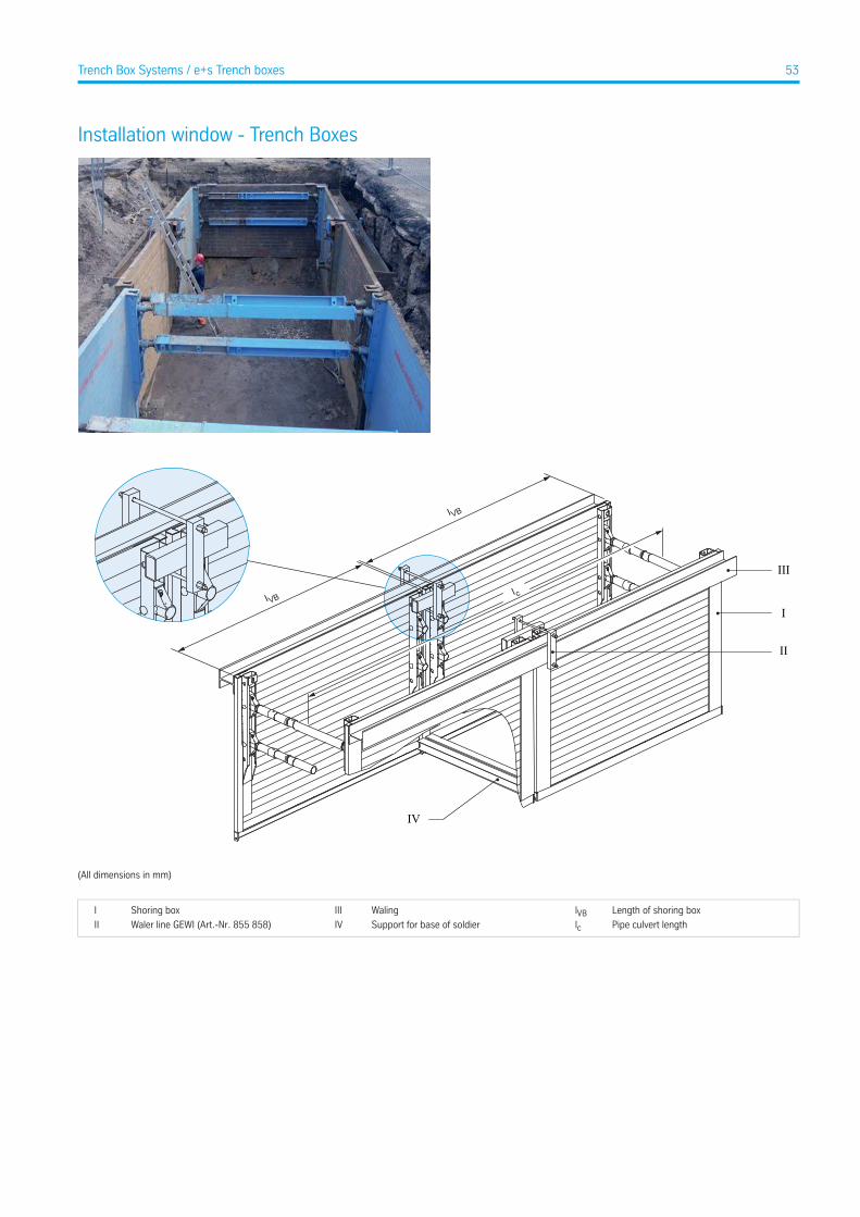
Installation window - Trench Boxes
III
I
II
IV
I VB
IVB
I c
(All dimensions in mm)
Length of shoring boxlVBWalingIIIShoring boxI
Pipe culvert lengthlcSupport for base of soldierIVWaler line GEWI (Art.-Nr. 855 858)II
53Trench Box Systems / e+s Trench boxes
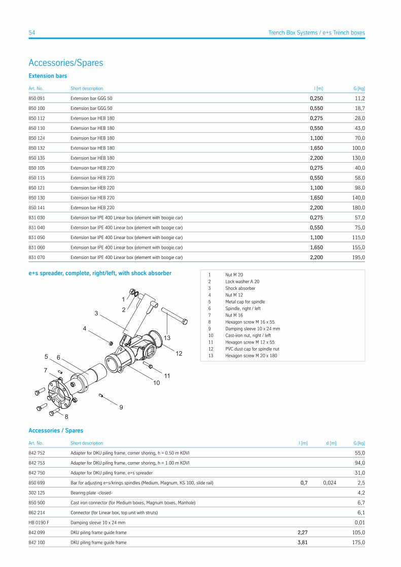
Accessories/SparesExtension bars
G [kg]l [m]Short descriptionArt. No.
11,20,250Extension bar GGG 50850 091
18,70,550Extension bar GGG 50850 100
28,00,275Extension bar HEB 180850 112
43,00,550Extension bar HEB 180850 110
70,01,100Extension bar HEB 180850 124
100,01,650Extension bar HEB 180850 132
130,02,200Extension bar HEB 180850 135
40,00,275Extension bar HEB 220850 105
58,00,550Extension bar HEB 220850 115
98,01,100Extension bar HEB 220850 121
140,01,650Extension bar HEB 220850 130
180,02,200Extension bar HEB 220850 141
57,00,275Extension bar IPE 400 Linear box (element with boogie car)831 030
75,00,550Extension bar IPE 400 Linear box (element with boogie car)831 040
115,01,100Extension bar IPE 400 Linear box (element with boogie car)831 050
155,01,650Extension bar IPE 400 Linear box (element with boogie car)831 060
195,02,200Extension bar IPE 400 Linear box (element with boogie car)831 070
e+s spreader, complete, right/left, with shock absorber Nut M 201
Lock washer A 202
Shock absorber3
Nut M 124
Metal cap for spindle5
Spindle, right / left6
Nut M 167
Hexagon screw M 16 x 558
Damping sleeve 10 x 24 mm9
Cast-iron nut, right / left10
Hexagon screw M 12 x 5511
PVC dust cap for spindle nut12
Hexagon screw M 20 x 18013
Accessories / Spares
G [kg]d [m]l [m]Short descriptionArt. No.
55,0Adapter for DKU piling frame, corner shoring, h = 0.50 m KDVI842 752
94,0Adapter for DKU piling frame, corner shoring, h = 1.00 m KDVI842 753
31,0Adapter for DKU piling frame, e+s spreader842 750
2,50,0240,7Bar for adjusting e+s/krings spindles (Medium, Magnum, KS 100, slide rail)850 699
4,2Bearing plate -closed-302 125
6,7Cast iron connector (for Medium boxes, Magnum boxes, Manhole)850 500
6,1Connector (for Linear box, top unit with struts)862 214
0,01Damping sleeve 10 x 24 mmHB 0190 F
105,02,27DKU piling frame guide frame842 099
175,03,81DKU piling frame guide frame842 100
54 Trench Box Systems / e+s Trench boxes
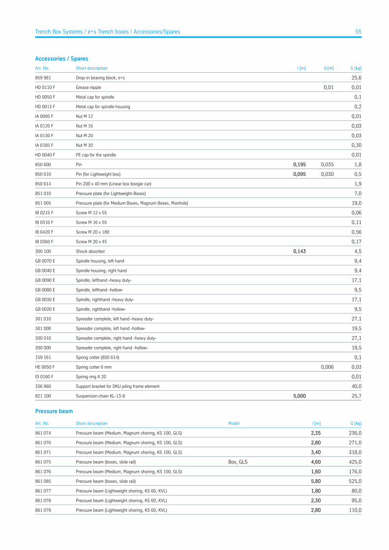
Accessories / Spares
G [kg]d [m]l [m]Short descriptionArt. No.
25,6Drop-in bearing block, e+s859 981
0,010,01Grease nippleHD 0110 F
0,1Metal cap for spindleHD 0050 F
0,2Metal cap for spindle housingHD 0013 F
0,01Nut M 12IA 0095 F
0,03Nut M 16IA 0120 F
0,03Nut M 20IA 0130 F
0,30Nut M 30IA 0185 F
0,01PE cap for the spindleHD 0040 F
1,80,0350,195Pin850 600
0,50,0300,095Pin (for Lightweight box)850 610
1,9Pin 200 x 40 mm (Linear box boogie car)850 614
7,0Pressure plate (for Lightweight-Boxes)851 010
19,0Pressure plate (for Medium Boxes, Magnum Boxes, Manhole)851 005
0,06Screw M 12 x 55IB 0215 F
0,11Screw M 16 x 55IB 0310 F
0,56Screw M 20 x 180IB 0420 F
0,17Screw M 20 x 45IB 0360 F
4,50,143Shock absorber300 100
9,4Spindle housing, left handGB 0070 E
9,4Spindle housing, right handGB 0040 E
17,1Spindle, lefthand -heavy duty-GB 0090 E
9,5Spindle, lefthand -hollow-GB 0080 E
17,1Spindle, righthand -heavy duty-GB 0030 E
9,5Spindle, righthand -hollow-GB 0020 E
27,1Spreader complete, left hand -heavy duty-301 010
19,5Spreader complete, left hand -hollow-301 000
27,1Spreader complete, right hand -heavy duty-300 010
19,5Spreader complete, right hand -hollow-300 000
0,1Spring cotter (850 614)159 161
0,030,006Spring cotter 6 mmHE 0050 F
0,01Spring ring A 20ID 0160 F
40,0Support bracket for DKU piling frame element336 960
25,75,000Suspension chain KL-13-8821 100
Pressure beam
G [kg]l [m]ModelShort descriptionArt. No.
236,02,35Pressure beam (Medium, Magnum shoring, KS 100, GLS)861 074
271,02,80Pressure beam (Medium, Magnum shoring, KS 100, GLS)861 070
318,03,40Pressure beam (Medium, Magnum shoring, KS 100, GLS)861 071
425,04,60Box, GLSPressure beam (boxes, slide rail)861 075
176,01,60Pressure beam (Medium, Magnum shoring, KS 100, GLS)861 076
525,05,80Pressure beam (boxes, slide rail)861 085
80,01,80Pressure beam (Lightweight shoring, KS 60, KVL)861 077
95,02,30Pressure beam (Lightweight shoring, KS 60, KVL)861 078
110,02,80Pressure beam (Lightweight shoring, KS 60, KVL)861 079
55Trench Box Systems / e+s Trench boxes / Accessories/Spares

Pressure beam
G [kg]l [m]ModelShort descriptionArt. No.
125,03,30Pressure beam (Lightweight shoring, KS 60, KVL)861 080
483,02,20Pressure beam (boxes, slide rail)861 090
56 Trench Box Systems / e+s Trench boxes
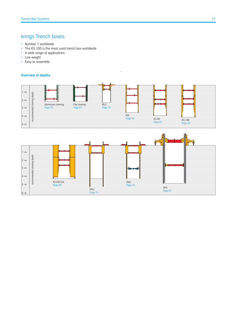
krings Trench boxes• Number 1 worldwide• The KS 100 is the most used trench box worldwide• A wide range of applications• Low weight• Easy to assemble
.Overview of depths
1 m
4 m
5 m
3 m
2 m
1 m
4 m
5 m
3 m
2 m
reco
mm
ende
d sh
orin
g de
pth
reco
mm
ende
d sh
orin
g de
pth
Aluminium shoringPage 79
Flex shoringPage 67
BLUPage 72
KLVPage 58 KS 60
Page 61KS 100Page 64
KS100 EckPage 69
DKUPage 74
DKUPage 74
DPVPage 87
6 m
57Trench Box Systems
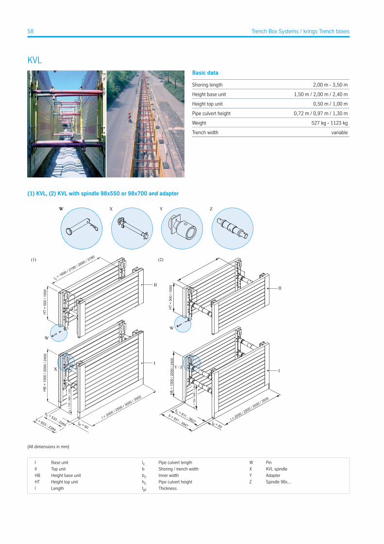
KVLBasic data
2,00 m - 3,50 mShoring length
1,50 m / 2,00 m / 2,40 mHeight base unit
0,50 m / 1,00 mHeight top unit
0,72 m / 0,97 m / 1,30 mPipe culvert height
527 kg - 1123 kgWeight
variableTrench width
(1) KVL, (2) KVL with spindle 98x550 or 98x700 and adapter
(1) (2)
W XW Y Z
HT
= 50
0 / 1
000
I c = 1690 / 2190 / 2690 / 3190
HT
= 50
0 / 1
000
I
II
W
W
II
HB
= 15
00 /
2000
/ 24
00
I = 2000 / 2500 / 3000 / 3500
tpl = 60
b = 653 - 2384
bc = 533 - 2264
Hc
= 72
0 / 9
80 /
1300
XI
b = 931 - 3947
bc = 811 - 3827 tpl = 60
I = 2000 / 2500 / 3
000 / 3500
Hc
= 70
0 / 9
60 /
1280
HB
= 15
00 /
2000
/ 24
00
Y / Z
(All dimensions in mm)
PinWPipe culvert lengthlcBase unitI
KVL spindleXShoring / trench widthbTop unitII
AdapterYInner widthbcHeight base unitHB
Spindle 98x...ZPipe culvert heighthcHeight top unitHT
ThicknesstplLengthl
58 Trench Box Systems / krings Trench boxes
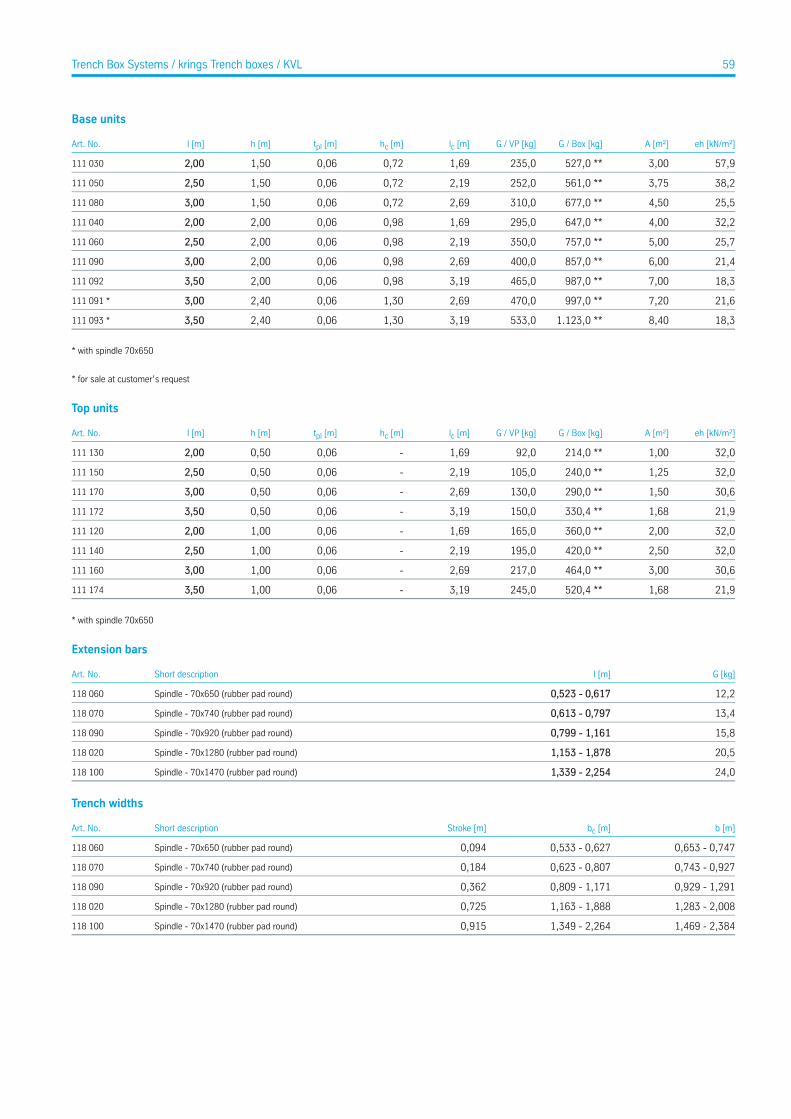
Base units
eh [kN/m²]A [m²]G / Box [kg]G / VP [kg]lc [m]hc [m]tpl [m]h [m]l [m]Art. No.
57,93,00527,0 **235,01,690,720,061,502,00111 030
38,23,75561,0 **252,02,190,720,061,502,50111 050
25,54,50677,0 **310,02,690,720,061,503,00111 080
32,24,00647,0 **295,01,690,980,062,002,00111 040
25,75,00757,0 **350,02,190,980,062,002,50111 060
21,46,00857,0 **400,02,690,980,062,003,00111 090
18,37,00987,0 **465,03,190,980,062,003,50111 092
21,67,20997,0 **470,02,691,300,062,403,00111 091 *
18,38,401.123,0 **533,03,191,300,062,403,50111 093 *
* with spindle 70x650
* for sale at customer’s request
Top units
eh [kN/m²]A [m²]G / Box [kg]G / VP [kg]lc [m]hc [m]tpl [m]h [m]l [m]Art. No.
32,01,00214,0 **92,01,69-0,060,502,00111 130
32,01,25240,0 **105,02,19-0,060,502,50111 150
30,61,50290,0 **130,02,69-0,060,503,00111 170
21,91,68330,4 **150,03,19-0,060,503,50111 172
32,02,00360,0 **165,01,69-0,061,002,00111 120
32,02,50420,0 **195,02,19-0,061,002,50111 140
30,63,00464,0 **217,02,69-0,061,003,00111 160
21,91,68520,4 **245,03,19-0,061,003,50111 174
* with spindle 70x650
Extension bars
G [kg]l [m]Short descriptionArt. No.
12,20,523 - 0,617Spindle - 70x650 (rubber pad round)118 060
13,40,613 - 0,797Spindle - 70x740 (rubber pad round)118 070
15,80,799 - 1,161Spindle - 70x920 (rubber pad round)118 090
20,51,153 - 1,878Spindle - 70x1280 (rubber pad round)118 020
24,01,339 - 2,254Spindle - 70x1470 (rubber pad round)118 100
Trench widths
b [m]bc [m]Stroke [m]Short descriptionArt. No.
0,653 - 0,7470,533 - 0,6270,094Spindle - 70x650 (rubber pad round)118 060
0,743 - 0,9270,623 - 0,8070,184Spindle - 70x740 (rubber pad round)118 070
0,929 - 1,2910,809 - 1,1710,362Spindle - 70x920 (rubber pad round)118 090
1,283 - 2,0081,163 - 1,8880,725Spindle - 70x1280 (rubber pad round)118 020
1,469 - 2,3841,349 - 2,2640,915Spindle - 70x1470 (rubber pad round)118 100
59Trench Box Systems / krings Trench boxes / KVL
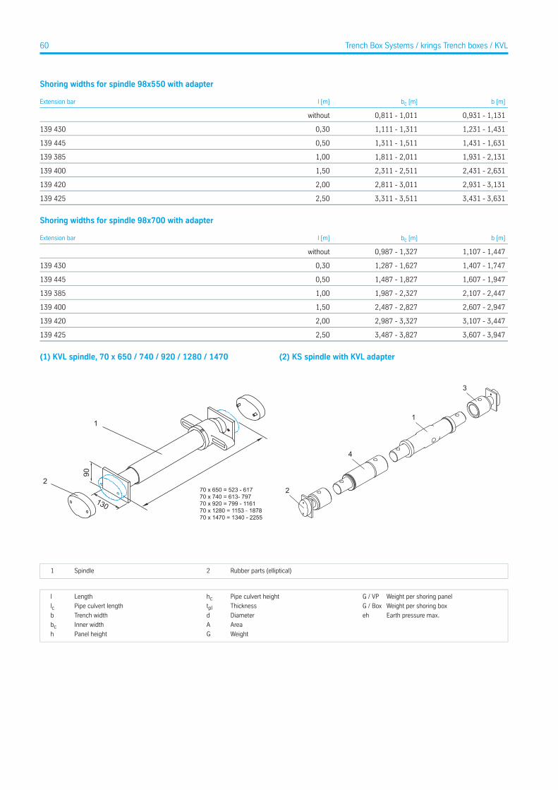
Shoring widths for spindle 98x550 with adapter
b [m]bc [m]l [m]Extension bar
0,931 - 1,1310,811 - 1,011without
1,231 - 1,4311,111 - 1,3110,30139 430
1,431 - 1,6311,311 - 1,5110,50139 445
1,931 - 2,1311,811 - 2,0111,00139 385
2,431 - 2,6312,311 - 2,5111,50139 400
2,931 - 3,1312,811 - 3,0112,00139 420
3,431 - 3,6313,311 - 3,5112,50139 425
Shoring widths for spindle 98x700 with adapter
b [m]bc [m]l [m]Extension bar
1,107 - 1,4470,987 - 1,327without
1,407 - 1,7471,287 - 1,6270,30139 430
1,607 - 1,9471,487 - 1,8270,50139 445
2,107 - 2,4471,987 - 2,3271,00139 385
2,607 - 2,9472,487 - 2,8271,50139 400
3,107 - 3,4472,987 - 3,3272,00139 420
3,607 - 3,9473,487 - 3,8272,50139 425
(1) KVL spindle, 70 x 650 / 740 / 920 / 1280 / 1470
1
130
90
270 x 650 = 523 - 61770 x 740 = 613- 79770 x 920 = 799 - 116170 x 1280 = 1153 - 187870 x 1470 = 1340 - 2255
(2) KS spindle with KVL adapter
2
4
3
1
Rubber parts (elliptical)2Spindle1
Weight per shoring panelG / VPPipe culvert heighthcLengthl
Weight per shoring boxG / BoxThicknesstplPipe culvert lengthlcEarth pressure max.ehDiameterdTrench widthb
AreaAInner widthbcWeightGPanel heighth
60 Trench Box Systems / krings Trench boxes / KVL
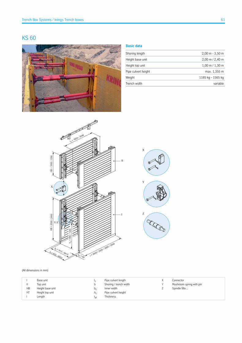
KS 60Basic data
2,00 m - 3,50 mShoring length
2,00 m / 2,40 mHeight base unit
1,00 m / 1,30 mHeight top unit
max. 1,355 mPipe culvert height
1185 kg - 1565 kgWeight
variableTrench width
X
Y
Z
HB
= 20
00 /
2400
b = 932 - 4933
bc = 812 - 4813 tpl = 60 I = 2000 / 2500 / 3000 / 3500h c =
995
/ 13
55
Y/Z
HB
= 10
00 /
1300
I c = 1603 - 3046
X
I
II
(All dimensions in mm)
ConnectorXPipe culvert lengthlcBase unitI
Mushroom spring with pinYShoring / trench widthbTop unitII
Spindle 98x...ZInner widthbcHeight base unitHB
Pipe culvert heighthcHeight top unitHT
ThicknesstplLengthl
61Trench Box Systems / krings Trench boxes
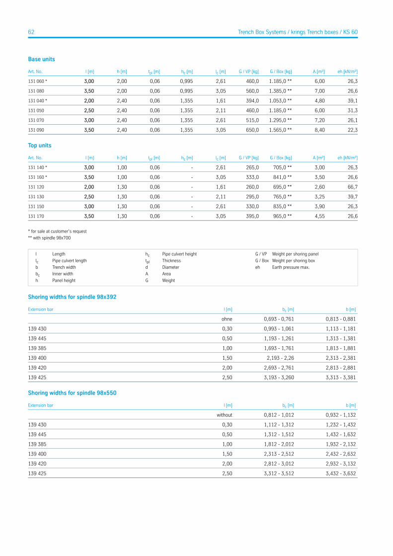
Base units
eh [kN/m²]A [m²]G / Box [kg]G / VP [kg]lc [m]hc [m]tpl [m]h [m]l [m]Art. No.
26,36,001.185,0 **460,02,610,9950,062,003,00131 060 *
26,67,001.385,0 **560,03,050,9950,062,003,50131 080
39,14,801.053,0 **394,01,611,3550,062,402,00131 040 *
31,36,001.185,0 **460,02,111,3550,062,402,50131 050
26,17,201.295,0 **515,02,611,3550,062,403,00131 070
22,38,401.565,0 **650,03,051,3550,062,403,50131 090
Top units
eh [kN/m²]A [m²]G / Box [kg]G / VP [kg]lc [m]hc [m]tpl [m]h [m]l [m]Art. No.
26,33,00705,0 **265,02,61-0,061,003,00131 140 *
26,63,50841,0 **333,03,05-0,061,003,50131 160 *
66,72,60695,0 **260,01,61-0,061,302,00131 120
39,73,25765,0 **295,02,11-0,061,302,50131 130
26,33,90835,0 **330,02,61-0,061,303,00131 150
26,64,55965,0 **395,03,05-0,061,303,50131 170
* for sale at customer’s request
** with spindle 98x700
Weight per shoring panelG / VPPipe culvert heighthcLengthl
Weight per shoring boxG / BoxThicknesstplPipe culvert lengthlcEarth pressure max.ehDiameterdTrench widthb
AreaAInner widthbcWeightGPanel heighth
Shoring widths for spindle 98x392
b [m]bc [m]l [m]Extension bar
0,813 - 0,8810,693 - 0,761ohne
1,113 - 1,1810,993 - 1,0610,30139 430
1,313 - 1,3811,193 - 1,2610,50139 445
1,813 - 1,8811,693 - 1,7611,00139 385
2,313 - 2,3812,193 - 2,261,50139 400
2,813 - 2,8812,693 - 2,7612,00139 420
3,313 - 3,3813,193 - 3,2602,50139 425
Shoring widths for spindle 98x550
b [m]bc [m]l [m]Extension bar
0,932 - 1,1320,812 - 1,012without
1,232 - 1,4321,112 - 1,3120,30139 430
1,432 - 1,6321,312 - 1,5120,50139 445
1,932 - 2,1321,812 - 2,0121,00139 385
2,432 - 2,6322,313 - 2,5121,50139 400
2,932 - 3,1322,812 - 3,0122,00139 420
3,432 - 3,6323,312 - 3,5122,50139 425
62 Trench Box Systems / krings Trench boxes / KS 60
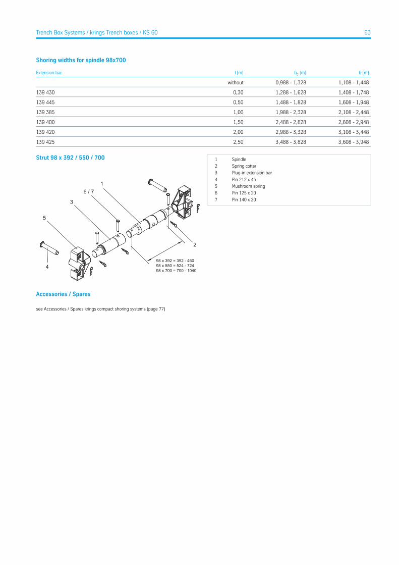
Shoring widths for spindle 98x700
b [m]bc [m]l [m]Extension bar
1,108 - 1,4480,988 - 1,328without
1,408 - 1,7481,288 - 1,6280,30139 430
1,608 - 1,9481,488 - 1,8280,50139 445
2,108 - 2,4481,988 - 2,3281,00139 385
2,608 - 2,9482,488 - 2,8281,50139 400
3,108 - 3,4482,988 - 3,3282,00139 420
3,608 - 3,9483,488 - 3,8282,50139 425
Strut 98 x 392 / 550 / 700
1
2
4
6 / 7
3
5
98 x 392 = 392 - 46098 x 550 = 524 - 72498 x 700 = 700 - 1040
Spindle1
Spring cotter2
Plug-in extension bar3
Pin 212 x 434
Mushroom spring5
Pin 125 x 206
Pin 140 x 207
Accessories / Spares
see Accessories / Spares krings compact shoring systems (page 77)
63Trench Box Systems / krings Trench boxes / KS 60
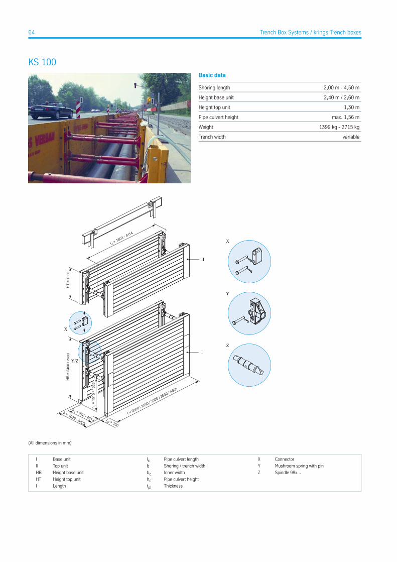
KS 100Basic data
2,00 m - 4,50 mShoring length
2,40 m / 2,60 mHeight base unit
1,30 mHeight top unit
max. 1,56 mPipe culvert height
1399 kg - 2715 kgWeight
variableTrench width
X
Y
Z
h c =
151
5 / 1
555
b = 1022 - 5023
bc = 812 - 4813 tpl = 100
HB
= 24
00 /
2600
HT
= 13
30
I = 2000 / 2500 / 3000 / 3500 / 4500
I c = 1603 - 4114
X
Y/Z
I
II
(All dimensions in mm)
ConnectorXPipe culvert lengthlcBase unitI
Mushroom spring with pinYShoring / trench widthbTop unitII
Spindle 98x...ZInner widthbcHeight base unitHB
Pipe culvert heighthcHeight top unitHT
ThicknesstplLengthl
64 Trench Box Systems / krings Trench boxes
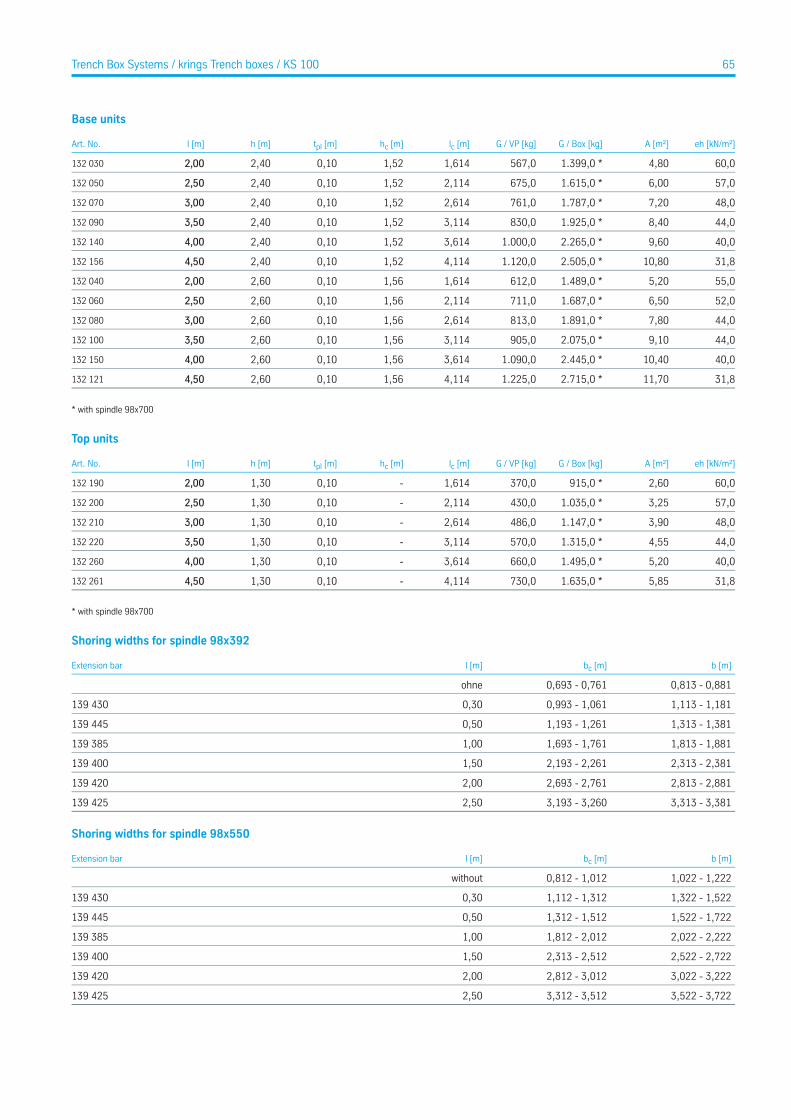
Base units
eh [kN/m²]A [m²]G / Box [kg]G / VP [kg]lc [m]hc [m]tpl [m]h [m]l [m]Art. No.
60,04,801.399,0 *567,01,6141,520,102,402,00132 030
57,06,001.615,0 *675,02,1141,520,102,402,50132 050
48,07,201.787,0 *761,02,6141,520,102,403,00132 070
44,08,401.925,0 *830,03,1141,520,102,403,50132 090
40,09,602.265,0 *1.000,03,6141,520,102,404,00132 140
31,810,802.505,0 *1.120,04,1141,520,102,404,50132 156
55,05,201.489,0 *612,01,6141,560,102,602,00132 040
52,06,501.687,0 *711,02,1141,560,102,602,50132 060
44,07,801.891,0 *813,02,6141,560,102,603,00132 080
44,09,102.075,0 *905,03,1141,560,102,603,50132 100
40,010,402.445,0 *1.090,03,6141,560,102,604,00132 150
31,811,702.715,0 *1.225,04,1141,560,102,604,50132 121
* with spindle 98x700
Top units
eh [kN/m²]A [m²]G / Box [kg]G / VP [kg]lc [m]hc [m]tpl [m]h [m]l [m]Art. No.
60,02,60915,0 *370,01,614-0,101,302,00132 190
57,03,251.035,0 *430,02,114-0,101,302,50132 200
48,03,901.147,0 *486,02,614-0,101,303,00132 210
44,04,551.315,0 *570,03,114-0,101,303,50132 220
40,05,201.495,0 *660,03,614-0,101,304,00132 260
31,85,851.635,0 *730,04,114-0,101,304,50132 261
* with spindle 98x700
Shoring widths for spindle 98x392
b [m]bc [m]l [m]Extension bar
0,813 - 0,8810,693 - 0,761ohne
1,113 - 1,1810,993 - 1,0610,30139 430
1,313 - 1,3811,193 - 1,2610,50139 445
1,813 - 1,8811,693 - 1,7611,00139 385
2,313 - 2,3812,193 - 2,2611,50139 400
2,813 - 2,8812,693 - 2,7612,00139 420
3,313 - 3,3813,193 - 3,2602,50139 425
Shoring widths for spindle 98x550
b [m]bc [m]l [m]Extension bar
1,022 - 1,2220,812 - 1,012without
1,322 - 1,5221,112 - 1,3120,30139 430
1,522 - 1,7221,312 - 1,5120,50139 445
2,022 - 2,2221,812 - 2,0121,00139 385
2,522 - 2,7222,313 - 2,5121,50139 400
3,022 - 3,2222,812 - 3,0122,00139 420
3,522 - 3,7223,312 - 3,5122,50139 425
65Trench Box Systems / krings Trench boxes / KS 100
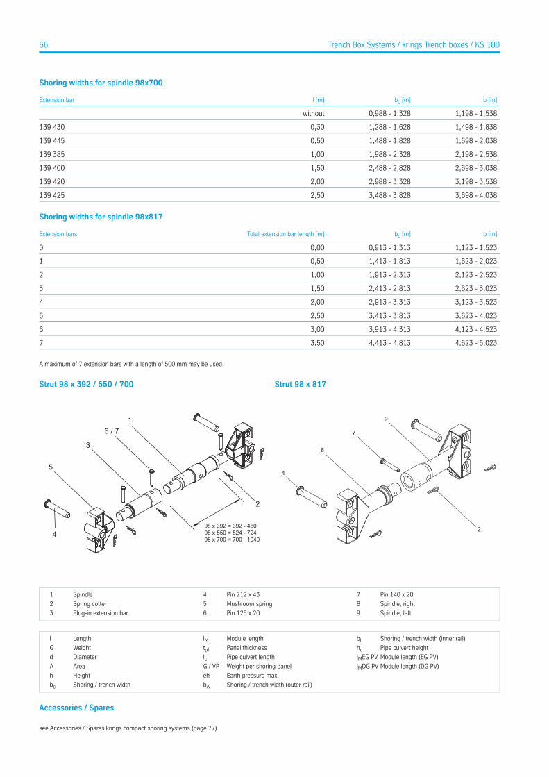
Shoring widths for spindle 98x700
b [m]bc [m]l [m]Extension bar
1,198 - 1,5380,988 - 1,328without
1,498 - 1,8381,288 - 1,6280,30139 430
1,698 - 2,0381,488 - 1,8280,50139 445
2,198 - 2,5381,988 - 2,3281,00139 385
2,698 - 3,0382,488 - 2,8281,50139 400
3,198 - 3,5382,988 - 3,3282,00139 420
3,698 - 4,0383,488 - 3,8282,50139 425
Shoring widths for spindle 98x817
b [m]bc [m]Total extension bar length [m]Extension bars
1,123 - 1,5230,913 - 1,3130,000
1,623 - 2,0231,413 - 1,8130,501
2,123 - 2,5231,913 - 2,3131,002
2,623 - 3,0232,413 - 2,8131,503
3,123 - 3,5232,913 - 3,3132,004
3,623 - 4,0233,413 - 3,8132,505
4,123 - 4,5233,913 - 4,3133,006
4,623 - 5,0234,413 - 4,8133,507
A maximum of 7 extension bars with a length of 500 mm may be used.
Strut 98 x 392 / 550 / 700
1
2
4
6 / 7
3
5
98 x 392 = 392 - 46098 x 550 = 524 - 72498 x 700 = 700 - 1040
Strut 98 x 817
4
8
7
9
2
Pin 140 x 207Pin 212 x 434Spindle1
Spindle, right8Mushroom spring5Spring cotter2
Spindle, left9Pin 125 x 206Plug-in extension bar3
Shoring / trench width (inner rail)bIModule lengthlMLengthl
Pipe culvert heighthcPanel thicknesstplWeightG
Module length (EG PV)lMEG PVPipe culvert lengthlcDiameterd
Module length (DG PV)lMDG PVWeight per shoring panelG / VPAreaA
Earth pressure max.ehHeighth
Shoring / trench width (outer rail)bAShoring / trench widthbc
Accessories / Spares
see Accessories / Spares krings compact shoring systems (page 77)
66 Trench Box Systems / krings Trench boxes / KS 100
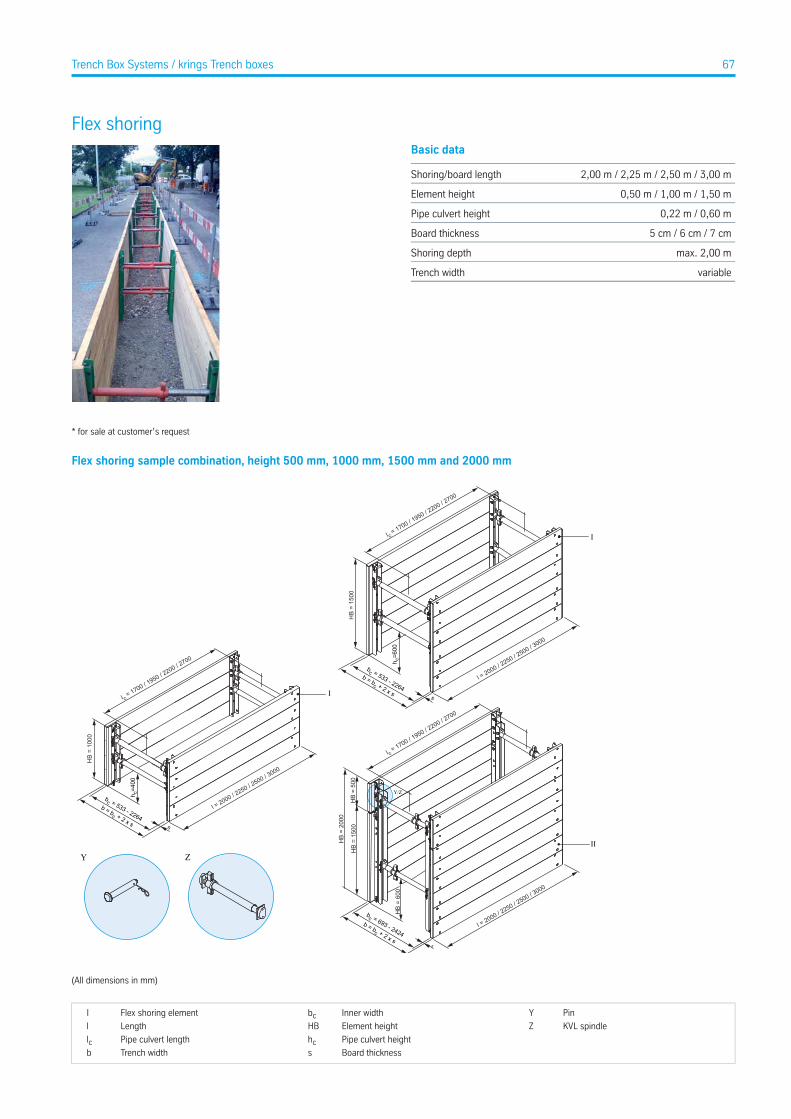
Flex shoringBasic data
2,00 m / 2,25 m / 2,50 m / 3,00 mShoring/board length
0,50 m / 1,00 m / 1,50 mElement height
0,22 m / 0,60 mPipe culvert height
5 cm / 6 cm / 7 cmBoard thickness
max. 2,00 mShoring depth
variableTrench width
* for sale at customer’s request
Flex shoring sample combination, height 500 mm, 1000 mm, 1500 mm and 2000 mm
Y Z
l c = 1700 / 1
950 / 2200 / 2
700
l = 2000 / 2250 / 2
500 / 3000
HB
= 10
00
h c=4
00
bc = 533 - 2264
b = bc + 2 x s s
I
l c = 1700 / 1
950 / 2200 / 2
700
HB
= 15
00
l = 2000 / 2250 / 2
500 / 3000
h c=6
00
s
bc = 533 - 2264
b = bc + 2 x s
I
Y/Z
II
l c = 1700 / 1
950 / 2200 / 2
700
HB
= 20
00
HB
= 15
00H
B =
500
HB
= 60
0
l = 2000 / 2250 / 2
500 / 3000
bc = 693 - 2424b = bc + 2 x s
(All dimensions in mm)
PinYInner widthbcFlex shoring elementI
KVL spindleZElement heightHBLengthl
Pipe culvert heighthcPipe culvert lengthlcBoard thicknesssTrench widthb
67Trench Box Systems / krings Trench boxes
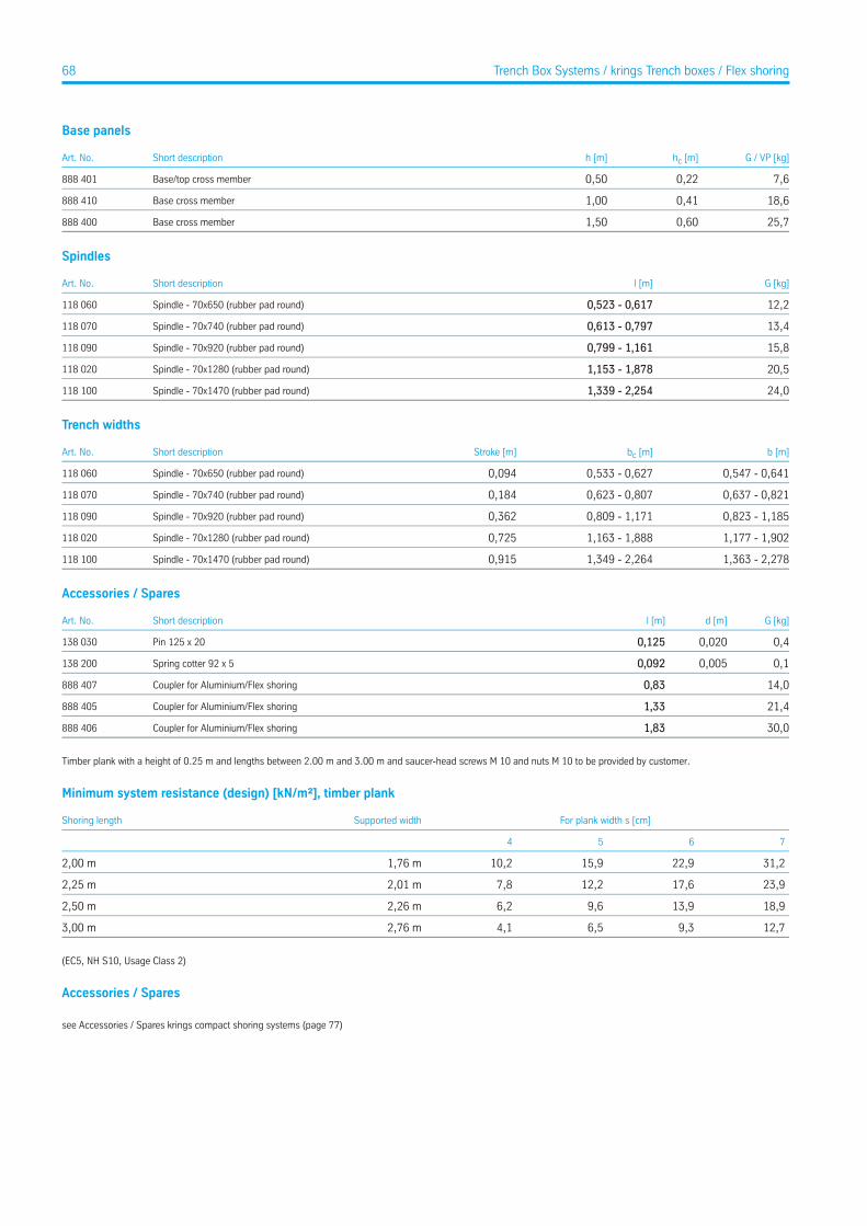
Base panels
G / VP [kg]hc [m]h [m]Short descriptionArt. No.
7,60,220,50Base/top cross member888 401
18,60,411,00Base cross member888 410
25,70,601,50Base cross member888 400
Spindles
G [kg]l [m]Short descriptionArt. No.
12,20,523 - 0,617Spindle - 70x650 (rubber pad round)118 060
13,40,613 - 0,797Spindle - 70x740 (rubber pad round)118 070
15,80,799 - 1,161Spindle - 70x920 (rubber pad round)118 090
20,51,153 - 1,878Spindle - 70x1280 (rubber pad round)118 020
24,01,339 - 2,254Spindle - 70x1470 (rubber pad round)118 100
Trench widths
b [m]bc [m]Stroke [m]Short descriptionArt. No.
0,547 - 0,6410,533 - 0,6270,094Spindle - 70x650 (rubber pad round)118 060
0,637 - 0,8210,623 - 0,8070,184Spindle - 70x740 (rubber pad round)118 070
0,823 - 1,1850,809 - 1,1710,362Spindle - 70x920 (rubber pad round)118 090
1,177 - 1,9021,163 - 1,8880,725Spindle - 70x1280 (rubber pad round)118 020
1,363 - 2,2781,349 - 2,2640,915Spindle - 70x1470 (rubber pad round)118 100
Accessories / Spares
G [kg]d [m]l [m]Short descriptionArt. No.
0,40,0200,125Pin 125 x 20138 030
0,10,0050,092Spring cotter 92 x 5138 200
14,00,83Coupler for Aluminium/Flex shoring888 407
21,41,33Coupler for Aluminium/Flex shoring888 405
30,01,83Coupler for Aluminium/Flex shoring888 406
Timber plank with a height of 0.25 m and lengths between 2.00 m and 3.00 m and saucer-head screws M 10 and nuts M 10 to be provided by customer.
Minimum system resistance (design) [kN/m²], timber plank
For plank width s [cm]Supported widthShoring length
7654
31,222,915,910,21,76 m2,00 m
23,917,612,27,82,01 m2,25 m
18,913,99,66,22,26 m2,50 m
12,79,36,54,12,76 m3,00 m
(EC5, NH S10, Usage Class 2)
Accessories / Spares
see Accessories / Spares krings compact shoring systems (page 77)
68 Trench Box Systems / krings Trench boxes / Flex shoring
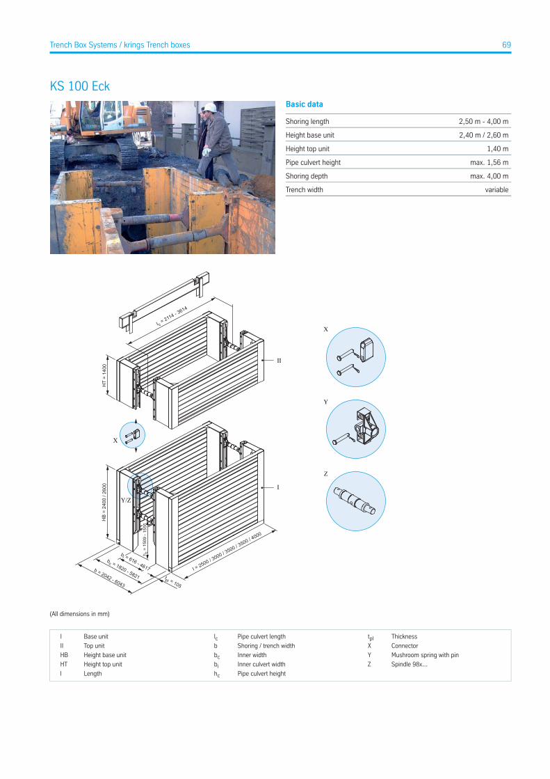
KS 100 EckBasic data
2,50 m - 4,00 mShoring length
2,40 m / 2,60 mHeight base unit
1,40 mHeight top unit
max. 1,56 mPipe culvert height
max. 4,00 mShoring depth
variableTrench width
X
Y
Z
HT
= 14
00
I c = 2114 - 3
614
I
II
HB
= 24
00 /
2600
b = 2042 - 6043
bc = 1820 - 5821
bi = 616 - 4617
tpl = 105
I = 2500 / 3000 / 3500 / 3500 / 4000
h c =
150
9 - 1
555
Y/Z
X
(All dimensions in mm)
ThicknesstplPipe culvert lengthlcBase unitI
ConnectorXShoring / trench widthbTop unitII
Mushroom spring with pinYInner widthbcHeight base unitHB
Spindle 98x...ZInner culvert widthbiHeight top unitHT
Pipe culvert heighthcLengthl
69Trench Box Systems / krings Trench boxes
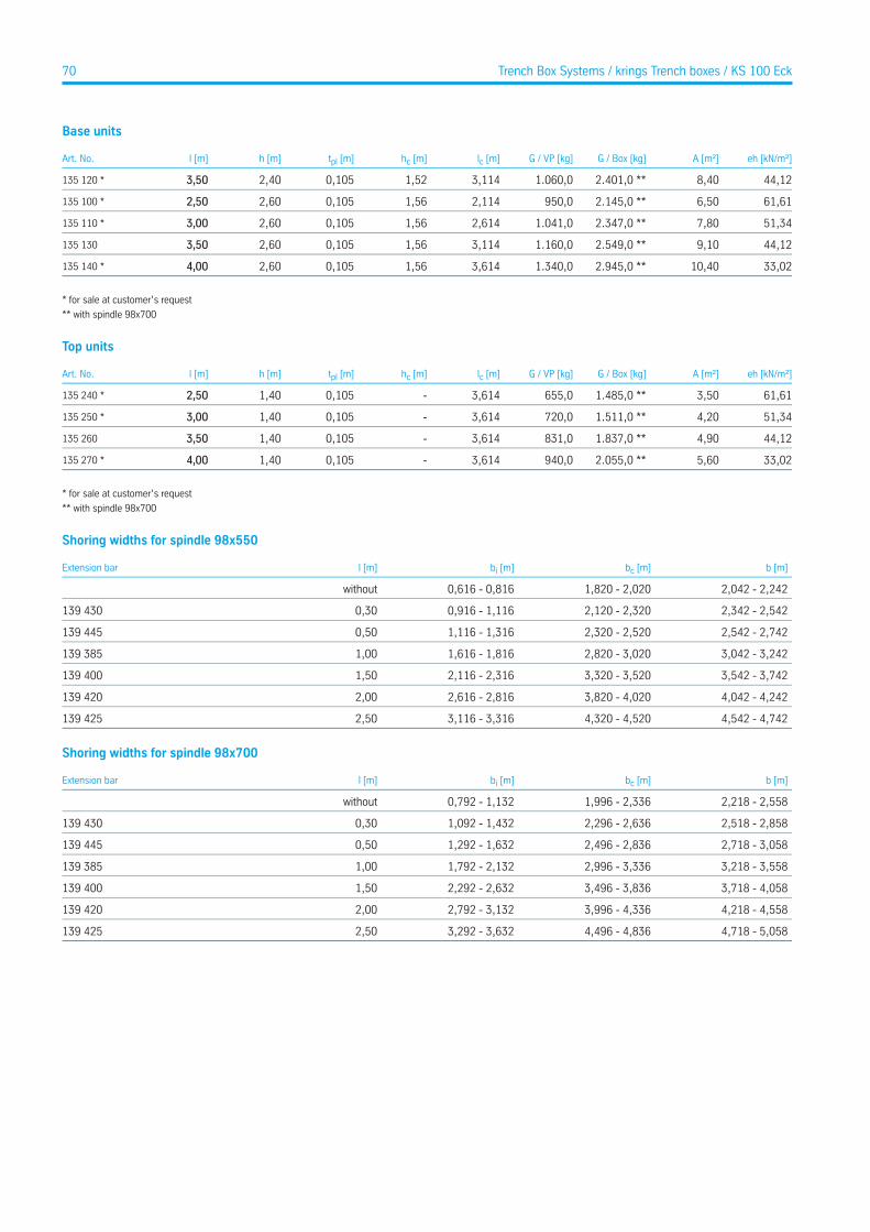
Base units
eh [kN/m²]A [m²]G / Box [kg]G / VP [kg]lc [m]hc [m]tpl [m]h [m]l [m]Art. No.
44,128,402.401,0 **1.060,03,1141,520,1052,403,50135 120 *
61,616,502.145,0 **950,02,1141,560,1052,602,50135 100 *
51,347,802.347,0 **1.041,02,6141,560,1052,603,00135 110 *
44,129,102.549,0 **1.160,03,1141,560,1052,603,50135 130
33,0210,402.945,0 **1.340,03,6141,560,1052,604,00135 140 *
* for sale at customer’s request
** with spindle 98x700
Top units
eh [kN/m²]A [m²]G / Box [kg]G / VP [kg]lc [m]hc [m]tpl [m]h [m]l [m]Art. No.
61,613,501.485,0 **655,03,614-0,1051,402,50135 240 *
51,344,201.511,0 **720,03,614-0,1051,403,00135 250 *
44,124,901.837,0 **831,03,614-0,1051,403,50135 260
33,025,602.055,0 **940,03,614-0,1051,404,00135 270 *
* for sale at customer’s request
** with spindle 98x700
Shoring widths for spindle 98x550
b [m]bc [m]bi [m]l [m]Extension bar
2,042 - 2,2421,820 - 2,0200,616 - 0,816without
2,342 - 2,5422,120 - 2,3200,916 - 1,1160,30139 430
2,542 - 2,7422,320 - 2,5201,116 - 1,3160,50139 445
3,042 - 3,2422,820 - 3,0201,616 - 1,8161,00139 385
3,542 - 3,7423,320 - 3,5202,116 - 2,3161,50139 400
4,042 - 4,2423,820 - 4,0202,616 - 2,8162,00139 420
4,542 - 4,7424,320 - 4,5203,116 - 3,3162,50139 425
Shoring widths for spindle 98x700
b [m]bc [m]bi [m]l [m]Extension bar
2,218 - 2,5581,996 - 2,3360,792 - 1,132without
2,518 - 2,8582,296 - 2,6361,092 - 1,4320,30139 430
2,718 - 3,0582,496 - 2,8361,292 - 1,6320,50139 445
3,218 - 3,5582,996 - 3,3361,792 - 2,1321,00139 385
3,718 - 4,0583,496 - 3,8362,292 - 2,6321,50139 400
4,218 - 4,5583,996 - 4,3362,792 - 3,1322,00139 420
4,718 - 5,0584,496 - 4,8363,292 - 3,6322,50139 425
70 Trench Box Systems / krings Trench boxes / KS 100 Eck
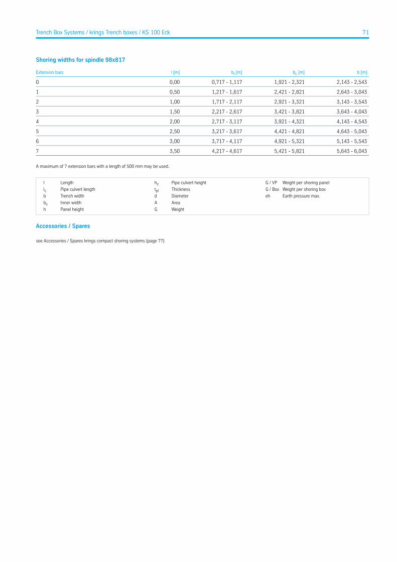
Shoring widths for spindle 98x817
b [m]bc [m]bi [m]l [m]Extension bars
2,143 - 2,5431,921 - 2,3210,717 - 1,1170,000
2,643 - 3,0432,421 - 2,8211,217 - 1,6170,501
3,143 - 3,5432,921 - 3,3211,717 - 2,1171,002
3,643 - 4,0433,421 - 3,8212,217 - 2,6171,503
4,143 - 4,5433,921 - 4,3212,717 - 3,1172,004
4,643 - 5,0434,421 - 4,8213,217 - 3,6172,505
5,143 - 5,5434,921 - 5,3213,717 - 4,1173,006
5,643 - 6,0435,421 - 5,8214,217 - 4,6173,507
A maximum of 7 extension bars with a length of 500 mm may be used.
Weight per shoring panelG / VPPipe culvert heighthcLengthl
Weight per shoring boxG / BoxThicknesstplPipe culvert lengthlcEarth pressure max.ehDiameterdTrench widthb
AreaAInner widthbcWeightGPanel heighth
Accessories / Spares
see Accessories / Spares krings compact shoring systems (page 77)
71Trench Box Systems / krings Trench boxes / KS 100 Eck
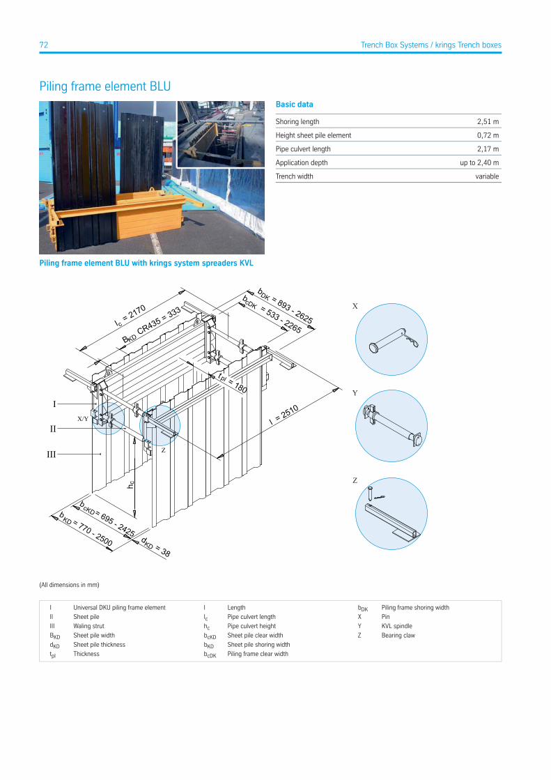
Piling frame element BLUBasic data
2,51 mShoring length
0,72 mHeight sheet pile element
2,17 mPipe culvert length
up to 2,40 mApplication depth
variableTrench width
Piling frame element BLU with krings system spreaders KVL
Y
Z
X
II
I
III
b = 770 - 2500 d = 38
b = 695 - 2425
cKD KD
KD
cl = 2170
b = 893 - 2625
b = 533 - 2265
cDK
DK
l = 2510
B CR435 = 333
KD
t = 180pl
h c
X/Y
Z
(All dimensions in mm)
Piling frame shoring widthbDKLengthlUniversal DKU piling frame elementI
PinXPipe culvert lengthlcSheet pileII
KVL spindleYPipe culvert heighthcWaling strutIII
Bearing clawZSheet pile clear widthbcKDSheet pile widthBKDSheet pile shoring widthbKDSheet pile thicknessdKDPiling frame clear widthbcDKThicknesstpl
72 Trench Box Systems / krings Trench boxes
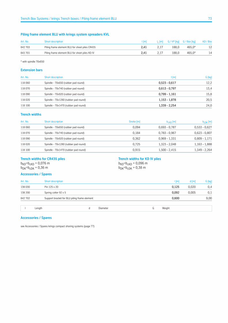
Piling frame element BLU with krings system spreaders KVL
KD / BoxG / Box [kg]G / VP [kg]lc [m]l [m]Short descriptionArt. No.
12465,0*188,02,172,41Piling frame element BLU for sheet piles CR435842 703
14465,0*188,02,172,41Piling frame element BLU for sheet piles KD IV843 701
* with spindle 70x650
Extension bars
G [kg]l [m]Short descriptionArt. No.
12,20,523 - 0,617Spindle - 70x650 (rubber pad round)118 060
13,40,613 - 0,797Spindle - 70x740 (rubber pad round)118 070
15,80,799 - 1,161Spindle - 70x920 (rubber pad round)118 090
20,51,153 - 1,878Spindle - 70x1280 (rubber pad round)118 020
24,01,339 - 2,254Spindle - 70x1470 (rubber pad round)118 100
Trench widths
bcDK [m]bcKD [m]Stroke [m]Short descriptionArt. No.
0,533 - 0,6270,693 - 0,7870,094Spindle - 70x650 (rubber pad round)118 060
0,623 - 0,8070,783 - 0,9670,184Spindle - 70x740 (rubber pad round)118 070
0,809 - 1,1710,969 - 1,3310,362Spindle - 70x920 (rubber pad round)118 090
1,163 - 1,8881,323 - 2,0480,725Spindle - 70x1280 (rubber pad round)118 020
1,349 - 2,2641,500 - 2,4150,915Spindle - 70x1470 (rubber pad round)118 100
Trench widths for CR435 pilesbKD=bcKD + 0,076 mbDK=bcDK + 0,36 m
Trench widths for KD IV pilesbKD=bcKD + 0,096 mbDK=bcDK + 0,38 m
Accessories / Spares
G [kg]d [m]l [m]Short descriptionArt. No.
0,40,0200,125Pin 125 x 20138 030
0,10,0050,092Spring cotter 92 x 5138 200
9,000,600Support bracket for BLU piling frame element842 702
WeightGDiameterdLengthl
Accessories / Spares
see Accessories / Spares krings compact shoring systems (page 77)
73Trench Box Systems / krings Trench boxes / Piling frame element BLU
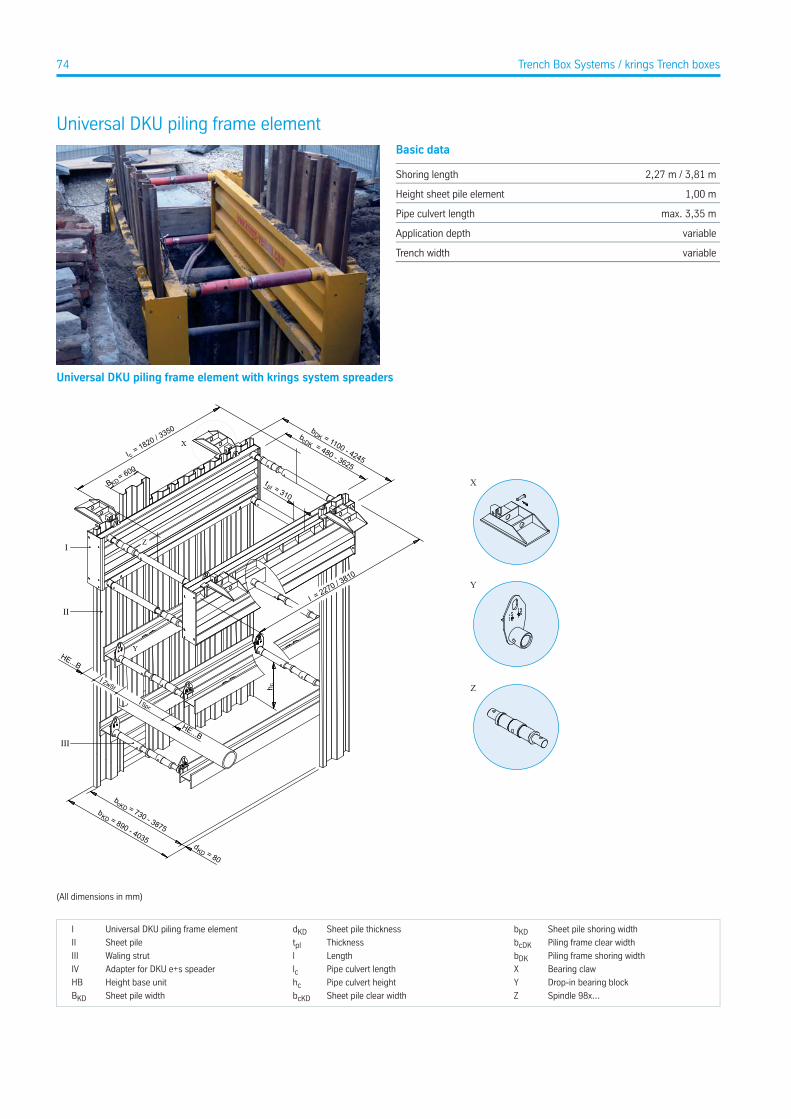
Universal DKU piling frame elementBasic data
2,27 m / 3,81 mShoring length
1,00 mHeight sheet pile element
max. 3,35 mPipe culvert length
variableApplication depth
variableTrench width
Universal DKU piling frame element with krings system spreaders
Y
Z
X
l = 2270 / 3810
II
I
III
b = 890 - 4035d = 80
b = 730 - 3875
l Spr.
HE...B
l ZwSt
HE...B
cl = 1820 / 3
350
B = 600
KD
b = 1100 - 4245
b = 480 - 3625
cDK
t = 310pl
DK
cKD KD
KD
h c
X
Y
Z
(All dimensions in mm)
Sheet pile shoring widthbKDSheet pile thicknessdKDUniversal DKU piling frame elementI
Piling frame clear widthbcDKThicknesstplSheet pileII
Piling frame shoring widthbDKLengthlWaling strutIII
Bearing clawXPipe culvert lengthlcAdapter for DKU e+s speaderIV
Drop-in bearing blockYPipe culvert heighthcHeight base unitHB
Spindle 98x...ZSheet pile clear widthbcKDSheet pile widthBKD
74 Trench Box Systems / krings Trench boxes
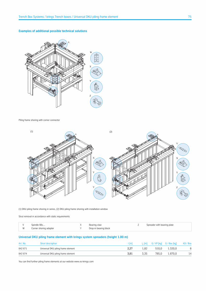
Examples of additional possible technical solutions
Y/Z
W
X
Z
Y
X
W
Piling frame shoring with corner connector
(2)
Y
V
X
Y/Z
V
X(1)
V
Y
X
Y
X
V
Z
(1) DKU piling frame shoring in series, (2) DKU piling frame shoring with installation window
Strut removal in accordance with static requirements
Spreader with bearing plateZBearing clawXSpindle 98x...V
Drop-in bearing blockYCorner shoring adapterW
Universal DKU piling frame element with krings system spreaders (height 1.00 m)
KD / BoxG / Box [kg]G / VP [kg]lc [m]l [m]Short descriptionArt. No.
81.320,0510,01,822,27Universal DKU piling frame element842 671
141.870,0785,03,353,81Universal DKU piling frame element842 674
You can find further piling frame elements at our website www.es-krings.com
75Trench Box Systems / krings Trench boxes / Universal DKU piling frame element
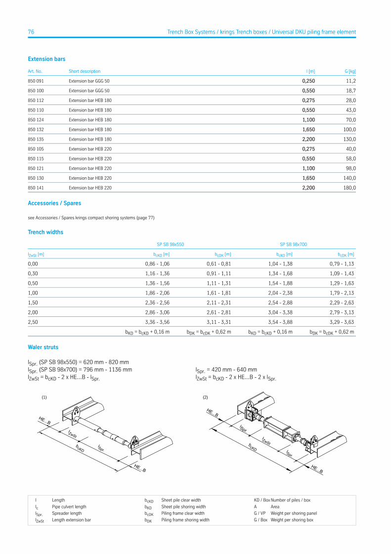
Extension bars
G [kg]l [m]Short descriptionArt. No.
11,20,250Extension bar GGG 50850 091
18,70,550Extension bar GGG 50850 100
28,00,275Extension bar HEB 180850 112
43,00,550Extension bar HEB 180850 110
70,01,100Extension bar HEB 180850 124
100,01,650Extension bar HEB 180850 132
130,02,200Extension bar HEB 180850 135
40,00,275Extension bar HEB 220850 105
58,00,550Extension bar HEB 220850 115
98,01,100Extension bar HEB 220850 121
140,01,650Extension bar HEB 220850 130
180,02,200Extension bar HEB 220850 141
Accessories / Spares
see Accessories / Spares krings compact shoring systems (page 77)
Trench widths
SP SB 98x700SP SB 98x550
bcDK [m]bcKD [m]bcDK [m]bcKD [m]lZwSt [m]
0,79 - 1,131,04 - 1,380,61 - 0,810,86 - 1,060,00
1,09 - 1,431,34 - 1,680,91 - 1,111,16 - 1,360,30
1,29 - 1,631,54 - 1,881,11 - 1,311,36 - 1,560,50
1,79 - 2,132,04 - 2,381,61 - 1,811,86 - 2,061,00
2,29 - 2,632,54 - 2,882,11 - 2,312,36 - 2,561,50
2,79 - 3,133,04 - 3,382,61 - 2,812,86 - 3,062,00
3,29 - 3,633,54 - 3,883,11 - 3,313,36 - 3,562,50
bDK = bcDK + 0,62 mbKD = bcKD + 0,16 mbDK = bcDK + 0,62 mbKD = bcKD + 0,16 m
Waler struts
lSpr. (SP SB 98x550) = 620 mm - 820 mmlSpr. (SP SB 98x700) = 796 mm - 1136 mmlZwSt = bcKD - 2 x HE...B - lSpr.
HE...B
HE...B
lZwSt
lSpr.bcKD
(1)
lSpr. = 420 mm - 640 mmlZwSt = bcKD - 2 x HE...B - 2 x lSpr.
lZwSt
HE...B
lSpr.
lSpr.
HE...B
bcKD
(2)
Number of piles / boxKD / BoxSheet pile clear widthbcKDLengthl
AreaASheet pile shoring widthbKDPipe culvert lengthlcWeight per shoring panelG / VPPiling frame clear widthbcDKSpreader lengthlSpr.Weight per shoring boxG / BoxPiling frame shoring widthbDKLength extension barlZwSt
76 Trench Box Systems / krings Trench boxes / Universal DKU piling frame element

Accessories/sparesStruts / Extension bars
G [kg]l [m]Short descriptionArt. No.
28,01,00Plug-in adapter pipe, ZW SB - 108x1000139 385
37,41,50Plug-in adapter pipe, ZW SB - 108x1500139 400
47,32,00Plug-in adapter pipe, ZW SB - 108x2000139 420
60,02,50Plug-in adapter pipe, ZW SB - 108x2500139 425
13,80,30Plug-in adapter pipe, ZW SB - 108x300139 430
17,70,50Plug-in adapter pipe, ZW SB - 108x500139 445
36,31,00Plug-in adapter pipe, ZW SB - 121x1000139 470
25,10,50Plug-in adapter pipe, ZW SB - 121x500139 510
38,0Spindle -heavy duty design-, lefthand, 98x817108 950
39,0Spindle -heavy duty design-, righthand, 98x817108 960
15,7Spindle to stick, 98x392138 260
22,0Spindle to stick, 98x550138 280
34,0Spindle to stick, 98x700138 290
76,9Spindle to stick, 98x817, complete138 300
Accessories / Spares
G [kg]d [m]l [m]Short descriptionArt. No.
55,0Adapter for DKU piling frame, corner shoring, h = 0.50 m KDVI842 752
94,0Adapter for DKU piling frame, corner shoring, h = 1.00 m KDVI842 753
2,50,0240,7Adjustment bar850 699
45,02,30Chain sling connection, 4-leg, 2300 x 13139 070
57,02,80Chain sling connection, 4-leg, 2800 x 13139 080
5,5Connection stanchion 290 x 145139 100
105,02,27DKU piling frame guide frame842 099
175,03,81DKU piling frame guide frame842 100
12,0Drop-in bearing block, adjustable, krings859 982
26,0Drop-in bearing block, e+s859 981
0,80,0850,100Fixing for pressure spring 100 x 85110 070
7,6KVL adapter for spindles 98x530 / 98x700119 011
13,0Mushroom FP 80138 170
0,03Nut M 16IA 0120 F
0,03Nut M 20IA 0130 F
0,40,0200,125Pin 125 x 20138 030
0,40,0200,140Pin 140 x 20138 040
2,50,0430,212Pin 212 x 43138 070
80,01,80Pressure beam (Lightweight shoring, KS 60, KVL)861 077
95,02,30Pressure beam (Lightweight shoring, KS 60, KVL)861 078
110,02,80Pressure beam (Lightweight shoring, KS 60, KVL)861 079
125,03,30Pressure beam (Lightweight shoring, KS 60, KVL)861 080
176,01,60Pressure beam (Medium, Magnum shoring, KS 100, GLS)861 076
236,02,35Pressure beam (Medium, Magnum shoring, KS 100, GLS)861 074
271,02,80Pressure beam (Medium, Magnum shoring, KS 100, GLS)861 070
318,03,40Pressure beam (Medium, Magnum shoring, KS 100, GLS)861 071
0,80,0540,084Pressure spring FP 80138 160
0,1Rubber parts GPU 30 x 40100 690
77Trench Box Systems / krings Trench boxes
Accessories / Spares
G [kg]d [m]l [m]Short descriptionArt. No.
0,11Screw M 16 x 55IB 0310 F
0,17Screw M 20 x 45IB 0360 F
0,10,0050,092Spring cotter 92 x 5138 200
40,0Support bracket for DKU piling frame element336 960
25,75,000Suspension chain KL-13-8821 100
WeightGDiameterdLengthl
78 Trench Box Systems / krings Trench boxes / Accessories/spares
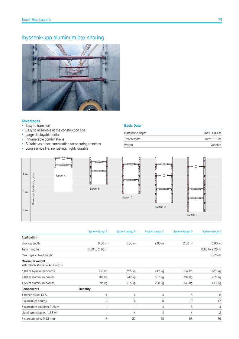
thyssenkrupp aluminum box shoring
Advantages• Easy to transport• Easy to assemble at the construction site• Large deployable radius• Innumerable combinations• Suitable as a box combination for securing trenches• Long service life, no rusting, highly durable
Basic Data
max. 4.00 mInstallation depth
max. 2.18mTrench width
variableWeight
3 m
2 m
1 m
System B
System A
System C
System D
System E
Reco
mm
ende
d sh
orin
g de
pth
System design ESystem design DSystem design CSystem design BSystem design A
Application
3.00 m2.50 m2.00 m1.50 m0.50 mShoring depth
0.68 to 2.26 m0.60 to 2.18 mTrench widths
0.75 mmax. pipe culvert height
Maximum weightwith trench struts Gi-A/129-218
635 kg532 kg417 kg325 kg130 kg3,00 m Aluminum boards
469 kg394 kg307 kg242 kg103 kg2.00 m aluminum boards
411 kg346 kg268 kg215 kg93 kg1.55 m aluminum boards
QuantityComponents
664441 trench struts Gi-A
12108622 aluminum boards
484--3 aluminum couplers 0.28 m
8444-aluminum couplers 1.35 m
7668483288 standard pins Ø 13 mm
79Trench Box Systems
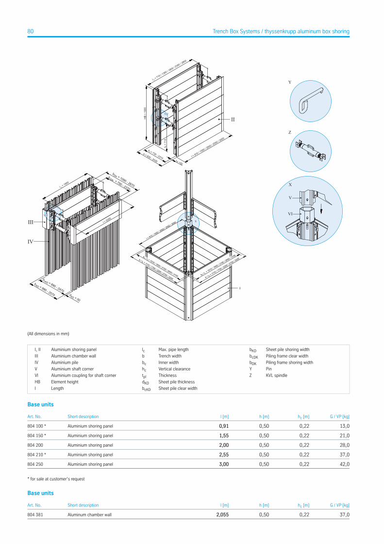
Y
Z
X
II
III
IV
V
VIX
cb / l = 1010 / 1650 / 2100 / 2650 / 3100
cA
b / l = 1010 / 1
650 / 2100 / 2
650 / 3100
b / l = 1110 / 1
750 / 2200 / 2
750 / 3200
cc
A
l = 910 / 1550 / 2
000 / 2550 / 3
000
I
b / l = 1110 / 1750 / 2200 / 2750 / 3200
(All dimensions in mm)
Sheet pile shoring widthbKDMax. pipe lengthlcAluminium shoring panelI, II
Piling frame clear widthbcDKTrench widthbAluminium chamber wallIII
Piling frame shoring widthbDKInner widthbcAluminium pileIV
PinYVertical clearancehcAluminium shaft cornerV
KVL spindleZThicknesstplAluminium coupling for shaft cornerVI
Sheet pile thicknessdKDElement heightHB
Sheet pile clear widthbcKDLengthl
Base units
G / VP [kg]hc [m]h [m]l [m]Short descriptionArt. No.
13,00,220,500,91Aluminium shoring panel804 100 *
21,00,220,501,55Aluminium shoring panel804 150 *
28,00,220,502,00Aluminium shoring panel804 200
37,00,220,502,55Aluminium shoring panel804 210 *
42,00,220,503,00Aluminium shoring panel804 250
* for sale at customer’s request
Base units
G / VP [kg]hc [m]h [m]l [m]Short descriptionArt. No.
37,00,220,502,055Aluminum chamber wall804 381
80 Trench Box Systems / thyssenkrupp aluminum box shoring
Spindles
G [kg]l [m]Short descriptionArt. No.
5,50,60 - 0,81Trench strut GI-A60-81 cm including 2 pins804 400
7,30,80 - 1,21Trench strut GI-A80-121 cm including 2 pins804 500
11,51,29 - 2,18Trench strut GI-A 129-218 cm including 2 pins804 550
Trench widths
with couplingwithout coupling
b [m]bc [m]b [m]bc [m]Stroke [m]Trench strut
0,68 - 0,890,58 - 0,790,60 - 0,810,50 - 0,710,21GI-A / 60-81
0,88 - 1,290,78 - 1,190,80 - 1,210,70 - 1,110,41GI-A / 80-121
1,37 - 2,261,27 - 2,161,29 - 2,181,19 - 2,080,89GI-A / 129-218
Trench widths
b KD [m]bc KD [m]b DK [m]bc DK [m]Stroke [m]Trench strut
0,81 - 1,020,71 - 0,920,91 - 1,120,60 - 0,810,21GI-A / 60-81
1,01 - 1,420,91 - 1,321,11 - 1,520,80 - 1,210,41GI-A / 80-121
1,50 - 2,391,40 - 2,291,60 - 2,491,29 - 2,180,89GI-A / 129-218
WeightGDiameterdLengthl
81Trench Box Systems / thyssenkrupp aluminum box shoring
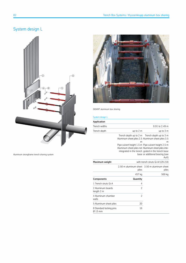
System design L
8
5
4 1
2
Aluminum strongframe trench shoring system
GIGANT aluminum box shoring
System design L
Application
0.91 to 2.49 mTrench widths
up to 3 mup to 2 mTrench depth
Trench depth up to 3 mAluminum sheet piles 3.5
mPipe culvert height 2.5 mAluminum sheet piles inte-grated in the trench baseor additional bracing (see
AuV)
Trench depth up to 2 mAluminum sheet piles 2.5
mPipe culvert height 1.5 mAluminum sheet piles not
integrated in the trenchbase
with trench struts Gi-A/129-218Maximum weight
3.50 m aluminum sheetpiles
2.50 m aluminum sheetpiles
569 kg457 kg
QuantityComponents
41 Trench struts Gi-A
22 Aluminum boardslength 2 m
24 Aluminum chamberwalls
205 Aluminum sheet piles
168 Standard locking pinsØ 13 mm
82 Trench Box Systems / thyssenkrupp aluminum box shoring
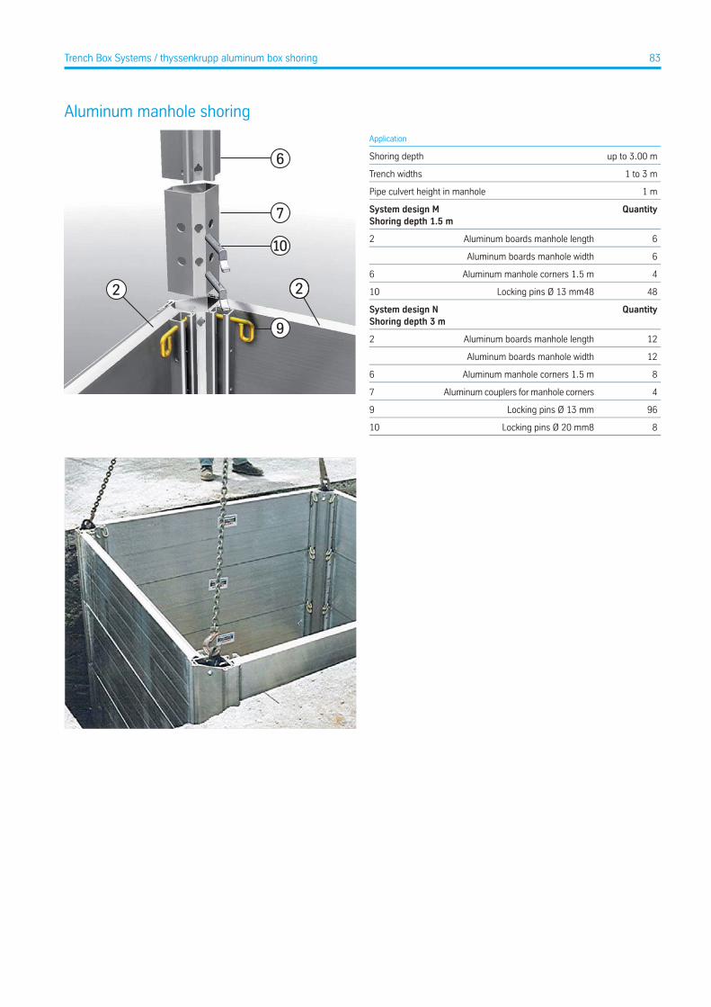
Aluminum manhole shoring
9
10
7
6
22
Application
up to 3.00 mShoring depth
1 to 3 mTrench widths
1 mPipe culvert height in manhole
QuantitySystem design MShoring depth 1.5 m
6Aluminum boards manhole length2
6Aluminum boards manhole width
4Aluminum manhole corners 1.5 m6
48Locking pins Ø 13 mm4810
QuantitySystem design NShoring depth 3 m
12Aluminum boards manhole length2
12Aluminum boards manhole width
8Aluminum manhole corners 1.5 m6
4Aluminum couplers for manhole corners7
96Locking pins Ø 13 mm9
8Locking pins Ø 20 mm810
83Trench Box Systems / thyssenkrupp aluminum box shoring
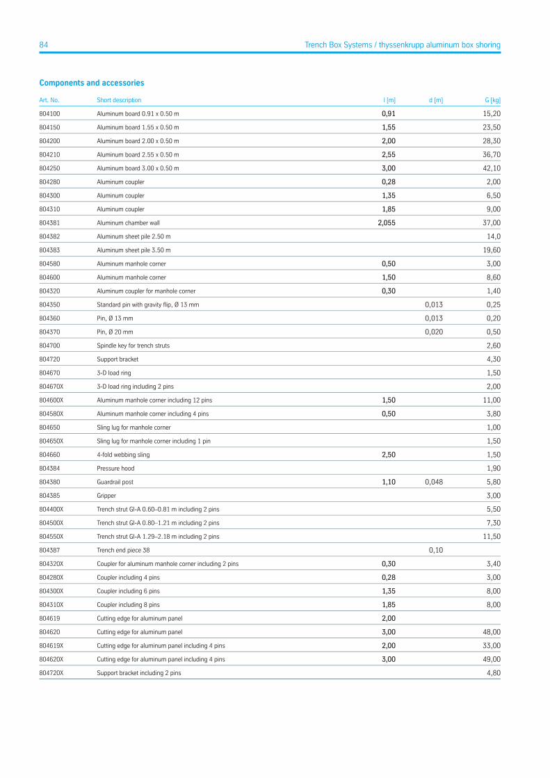
Components and accessories
G [kg]d [m]l [m]Short descriptionArt. No.
15,200,91Aluminum board 0.91 x 0.50 m804100
23,501,55Aluminum board 1.55 x 0.50 m804150
28,302,00Aluminum board 2.00 x 0.50 m804200
36,702,55Aluminum board 2.55 x 0.50 m804210
42,103,00Aluminum board 3.00 x 0.50 m804250
2,000,28Aluminum coupler804280
6,501,35Aluminum coupler804300
9,001,85Aluminum coupler804310
37,002,055Aluminum chamber wall804381
14,0Aluminum sheet pile 2.50 m804382
19,60Aluminum sheet pile 3.50 m804383
3,000,50Aluminum manhole corner804580
8,601,50Aluminum manhole corner804600
1,400,30Aluminum coupler for manhole corner804320
0,250,013Standard pin with gravity flip, Ø 13 mm804350
0,200,013Pin, Ø 13 mm804360
0,500,020Pin, Ø 20 mm804370
2,60Spindle key for trench struts804700
4,30Support bracket804720
1,503-D load ring804670
2,003-D load ring including 2 pins804670X
11,001,50Aluminum manhole corner including 12 pins804600X
3,800,50Aluminum manhole corner including 4 pins804580X
1,00Sling lug for manhole corner804650
1,50Sling lug for manhole corner including 1 pin804650X
1,502,504-fold webbing sling804660
1,90Pressure hood804384
5,800,0481,10Guardrail post804380
3,00Gripper804385
5,50Trench strut GI-A 0.60–0.81 m including 2 pins804400X
7,30Trench strut GI-A 0.80–1.21 m including 2 pins804500X
11,50Trench strut GI-A 1.29–2.18 m including 2 pins804550X
0,10Trench end piece 38804387
3,400,30Coupler for aluminum manhole corner including 2 pins804320X
3,000,28Coupler including 4 pins804280X
8,001,35Coupler including 6 pins804300X
8,001,85Coupler including 8 pins804310X
2,00Cutting edge for aluminum panel804619
48,003,00Cutting edge for aluminum panel804620
33,002,00Cutting edge for aluminum panel including 4 pins804619X
49,003,00Cutting edge for aluminum panel including 4 pins804620X
4,80Support bracket including 2 pins804720X
84 Trench Box Systems / thyssenkrupp aluminum box shoring
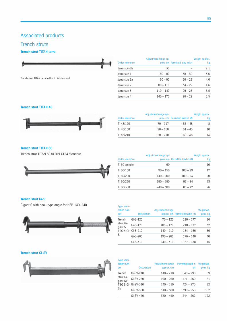
Associated products
Trench strutsTrench strut TITAN terra
Trench strut TITAN terra to DIN 4124 standard
Weight approx.
kgPermitted load in kN
Adjustment range ap-
prox. cmOrder reference
2.1–30terra spindle
3.638 – 3050 – 80terra size 1
4.036 – 2960 – 90terra size 1a
4.634 – 2980 – 110terra size 2
5.529 – 23110 – 140terra size 3
6.526 – 22140 – 170terra size 4
Trench strut TITAN 48
Weight approx.
kgPermitted load in kN
Adjustment range ap-
prox. cmOrder reference
863 – 4870 – 117Ti 48/120
1061 – 4590 – 150Ti 48/150
1360 – 38120 – 210Ti 48/210
Trench strut TITAN 60
Trench strut TITAN 60 to DIN 4124 standard Weight approx.
kgPermitted load in kN
Adjustment range ap-
prox. cmOrder reference
10–60Ti 60 spindle
17100 – 9990 – 150Ti 60/150
20100 – 93140 – 200Ti 60/200
2395 – 84190 – 250Ti 60/250
2685 – 72240 – 300Ti 60/300
Trench strut Gi-S
Gigant S with hook-type angle for HEB 140–240
Weight ap-
prox. kgPermitted load in kN
Adjustment range
approx. cmDescription
Type verifi-
cation num-
ber
Trenchstrut Gi-gant STBG 3-Gi-S
26210 – 17770 – 120Gi-S-120
32210 – 177105 – 170Gi-S-170
36184 – 156140 – 210Gi-S-210
40176 – 140190 – 260Gi-S-260
45157 – 138240 – 310Gi-S-310
Trench strut Gi-SV
Weight ap-
prox. kg
Permitted load in
kN
Adjustment range
approx. cmDescription
Type verifi-
cation num-
ber
Trenchstrut Gi-gant SVTBG 3-Gi-SV
69548 – 290140 – 210Gi-SV-210
81471 – 260190 – 260Gi-SV-260
92424 – 270240 – 310Gi-SV-310
107390 – 258310 – 380Gi-SV-380
122344 – 262380 – 450Gi-SV-450
85
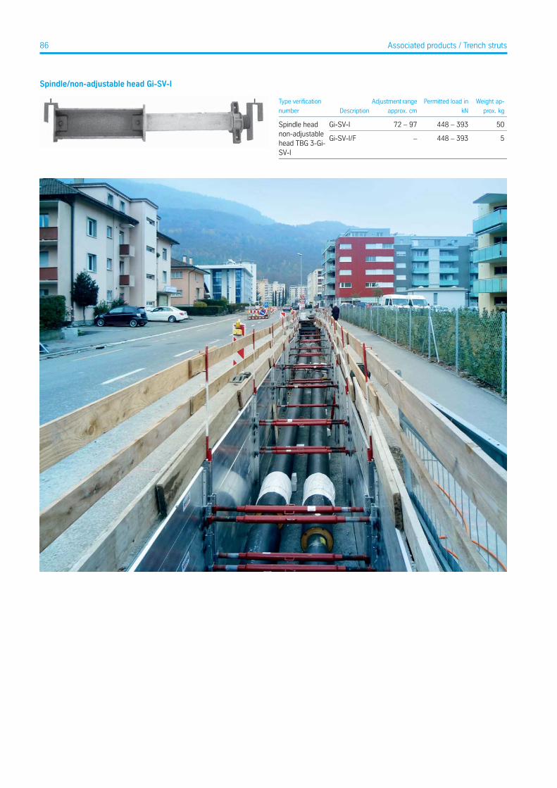
Spindle/non-adjustable head Gi-SV-I
Weight ap-
prox. kg
Permitted load in
kN
Adjustment range
approx. cmDescription
Type verification
number
Spindle headnon-adjustablehead TBG 3-Gi-SV-I
50448 – 39372 – 97Gi-SV-I
5448 – 393–Gi-SV-I/F
86 Associated products / Trench struts

Sheet pile machine DPVBasic data
5,50 m / 6,70 mShoring length
1,00 m - 3,00 mShoring width
4,50 m / 5,50 mShoring depth
7,65 t / 9,00 tPressing force
14 pcs. / 18 pcs.Number of sheet piles
Sheet pile machine DPV
Y
Z
Y/Z
I c = 4790 / 6
040
I = 5500 / 6700
92
bc = 1000 - 3000
b = 1184 - 3184
(All dimensions in mm)
Drop-in bearing blockYShoring / trench widthbLengthl
Spreader with bearing plateZInner widthbcPipe culvert lengthlc
Technical Data
eh [kN/m²]Pressing force [t]Sheet pilesT [m]lc [m]bc [m]l [m]Short descriptionArt. No.
25,807,6514 KD 750 / 104,504,791,00 - 3,005,50DPV 500285 100
28,589,0018 KD 750 / 105,506,041,00 - 3,006,70DPV 600285 110
87Associated products
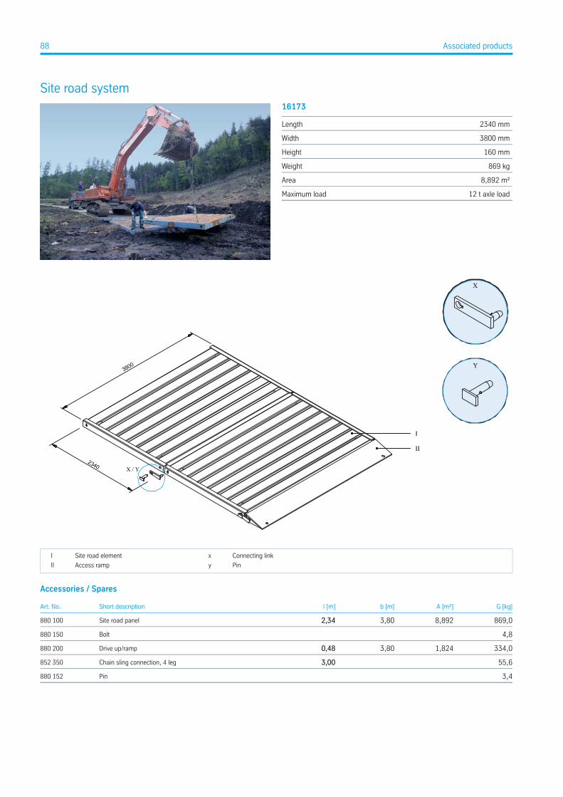
Site road system16173
2340 mmLength
3800 mmWidth
160 mmHeight
869 kgWeight
8,892 m²Area
12 t axle loadMaximum load
Connecting linkxSite road elementI
PinyAccess rampII
Accessories / Spares
G [kg]A [m²]b [m]l [m]Short descriptionArt. No.
869,08,8923,802,34Site road panel880 100
4,8Bolt880 150
334,01,8243,800,48Drive up/ramp880 200
55,63,00Chain sling connection, 4 leg852 350
3,4Pin880 152
88 Associated products
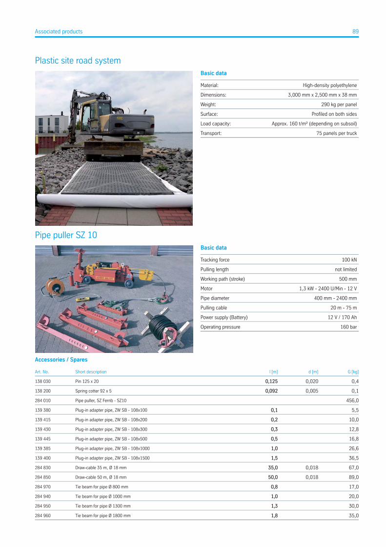
Plastic site road systemBasic data
High-density polyethyleneMaterial:
3,000 mm x 2,500 mm x 38 mmDimensions:
290 kg per panelWeight:
Profiled on both sidesSurface:
Approx. 160 t/m² (depending on subsoil)Load capacity:
75 panels per truckTransport:
Pipe puller SZ 10Basic data
100 kNTracking force
not limitedPulling length
500 mmWorking path (stroke)
1,3 kW - 2400 U/Min - 12 VMotor
400 mm - 2400 mmPipe diameter
20 m - 75 mPulling cable
12 V / 170 AhPower supply (Battery)
160 barOperating pressure
Accessories / Spares
G [kg]d [m]l [m]Short descriptionArt. No.
0,40,0200,125Pin 125 x 20138 030
0,10,0050,092Spring cotter 92 x 5138 200
456,0Pipe puller, SZ Fernb - SZ10284 010
5,50,1Plug-in adapter pipe, ZW SB - 108x100139 380
10,00,2Plug-in adapter pipe, ZW SB - 108x200139 415
12,80,3Plug-in adapter pipe, ZW SB - 108x300139 430
16,80,5Plug-in adapter pipe, ZW SB - 108x500139 445
26,61,0Plug-in adapter pipe, ZW SB - 108x1000139 385
36,51,5Plug-in adapter pipe, ZW SB - 108x1500139 400
67,00,01835,0Draw-cable 35 m, Ø 18 mm284 830
89,00,01850,0Draw-cable 50 m, Ø 18 mm284 850
17,00,8Tie beam for pipe Ø 800 mm284 970
20,01,0Tie beam for pipe Ø 1000 mm284 940
30,01,3Tie beam for pipe Ø 1300 mm284 950
35,01,8Tie beam for pipe Ø 1800 mm284 960
89Associated products
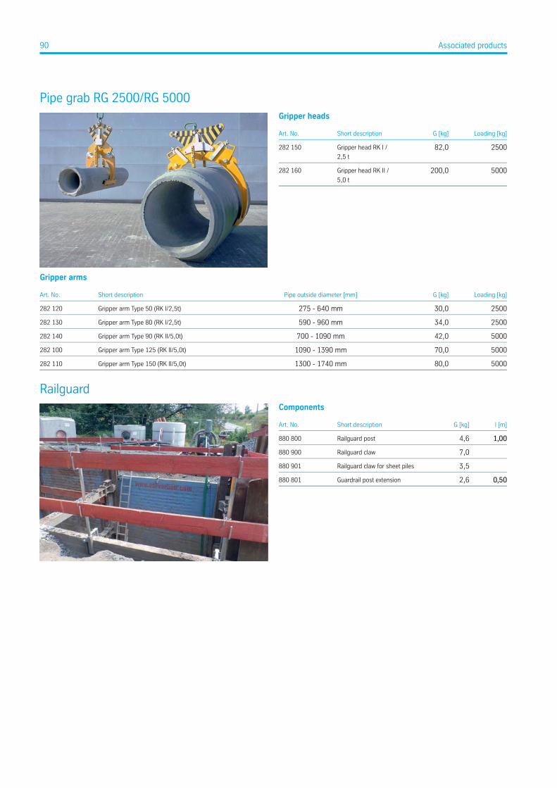
Pipe grab RG 2500/RG 5000Gripper heads
Loading [kg]G [kg]Short descriptionArt. No.
250082,0Gripper head RK I /
2,5 t
282 150
5000200,0Gripper head RK II /
5,0 t
282 160
Gripper arms
Loading [kg]G [kg]Pipe outside diameter [mm]Short descriptionArt. No.
250030,0275 - 640 mmGripper arm Type 50 (RK I/2,5t)282 120
250034,0590 - 960 mmGripper arm Type 80 (RK I/2,5t)282 130
500042,0700 - 1090 mmGripper arm Type 90 (RK II/5,0t)282 140
500070,01090 - 1390 mmGripper arm Type 125 (RK II/5,0t)282 100
500080,01300 - 1740 mmGripper arm Type 150 (RK II/5,0t)282 110
RailguardComponents
l [m]G [kg]Short descriptionArt. No.
1,004,6Railguard post880 800
7,0Railguard claw880 900
3,5Railguard claw for sheet piles880 901
0,502,6Guardrail post extension880 801
90 Associated products
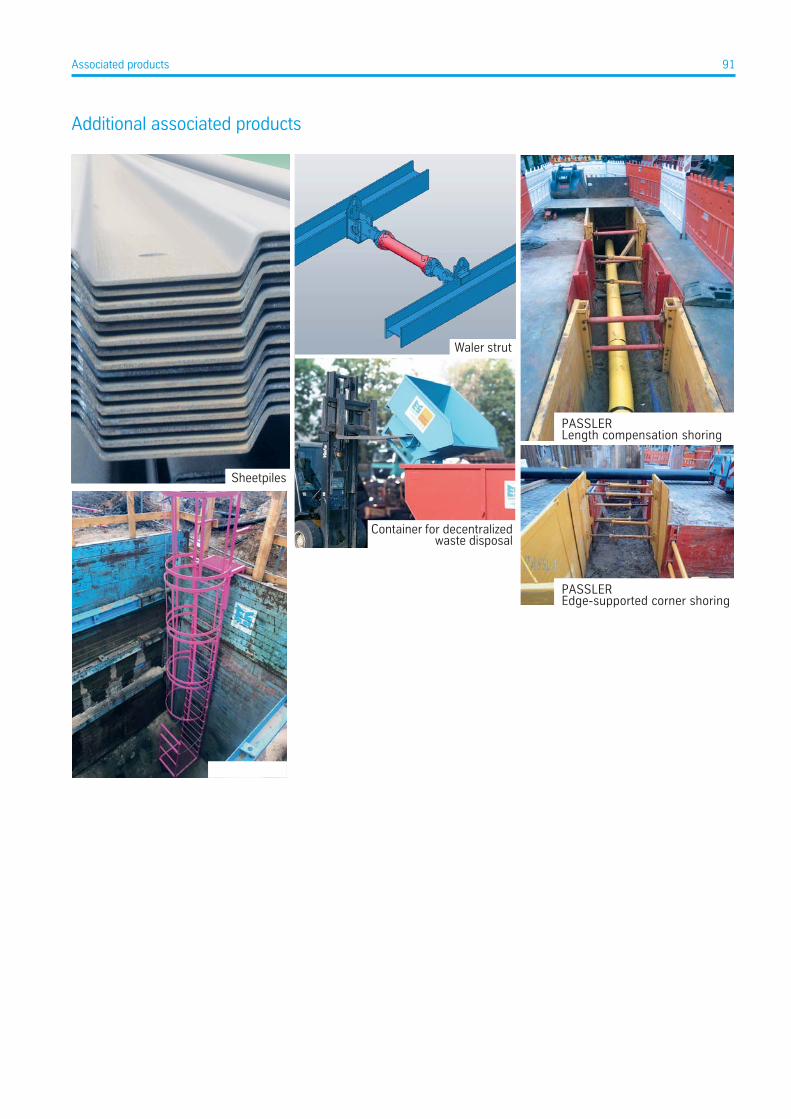
Additional associated products
Sheetpiles
Waler strut
Container for decentralizedwaste disposal
PASSLEREdge-supported corner shoring
PASSLERLength compensation shoring
91Associated products
Sub
ject
to c
hang
e, T
KIN
F.16
9.e.
1.1.
08
-18.
DSMaterials Services
Infrastructure
thyssenkrupp Infrastructure GmbH Hollestraße 7a 45127 Essen, Germany P: +49 201 844-562313 F: +49 201 844-562333 [email protected] www.thyssenkrupp-infrastructure.com
Trench Shoring thyssenkrupp Infrastructure GmbH Ottost. 30 41836 Hückelhoven, Germany P: +49 2433 453-0 [email protected]
Sales Branches
Australia, Indonesia, Japan, New Zealand thyssenkrupp Infrastructure Ltd. Suite 502, 11 Help Street Chatswood NSW 2067, Australia P: +61 2 8448-3555 F: +61 2 9411-4311 www.thyssenkrupp-infrastructure.com.au
Baltic States UAB thyssenkrupp Baltija Minijos g. 180 93269 Klaipeda, Lithuania P: +370 46 355-401 F: +370 46 355-032 www.thyssenkrupp-baltija.lt
Brazil thyssenkrupp Infrastructure Brasil Av. Rio Branco 124, sl 1602 CEP 20040-001 Rio de Janeiro, Rio de Janeiro, Brazil P: +55 3282-5245 www.thyssenkrupp-infrastructure.com
Kazakhstan TOO thyssenkrupp Infrastructure Kazakhstan Republic of Kazakhstan 050008 Almaty, Prospect Abaja 109 W, BC Globus, office 1 P: +7 727 356 15 50 F: +7 727 356 15 50 www.tkif-kz.com
Russian Federation OOO thyssenkrupp Infrastructure Prospekt Bolschevikov 54 B, office 211 193315 St.-Petersburg Russian Federation P: +7 812 337-6510 F: +7 812 337-6511 [email protected] www.tkif.ru
United Arab Emirates, Iraq thyssenkrupp Infrastructure GmbH Abu Dhabi c/o Royal Business Center Al Whada City Tower, 11th St, Hazaa Bin Zayed the First Street Abu Dhabi, United Arab Emirates P.O. Box 127432 P: +971 2 8157-860 F: +971 2 8157-888 [email protected] www.sheetpiling.ae