Embed Size (px)
Citation preview

Modular Shoring System
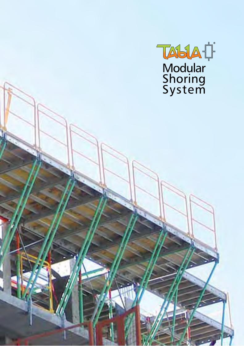
Modular ShoringSystem
Table of contentsIntroduction ....................................... 1
Procedures Erection ......................................... 4 Stripping ....................................... 6 Shoring, Backshoring, Reshoring ... 8 Cantilever Erection ......................... 10 Cantilever Stripping ....................... 12 Ramps ........................................... 14 Pioneer High Floor System ............. 16 Infill Components .......................... 18 Architectural Bridge Strips ............. 20
Tabla Components Props ............................................. 22 Panels ............................................ 24 Beams, Hangers ............................ 26 Cantilever Components ................. 27 Gate Brace ..................................... 27 Beams, Hangers and Braces ........... 28 Architectural Bridge Strips ............. 29
Tabla Safety Tabla Code of Safe Practices ......... 30 Tabla Safety Notices ...................... 31
E.&O.E.
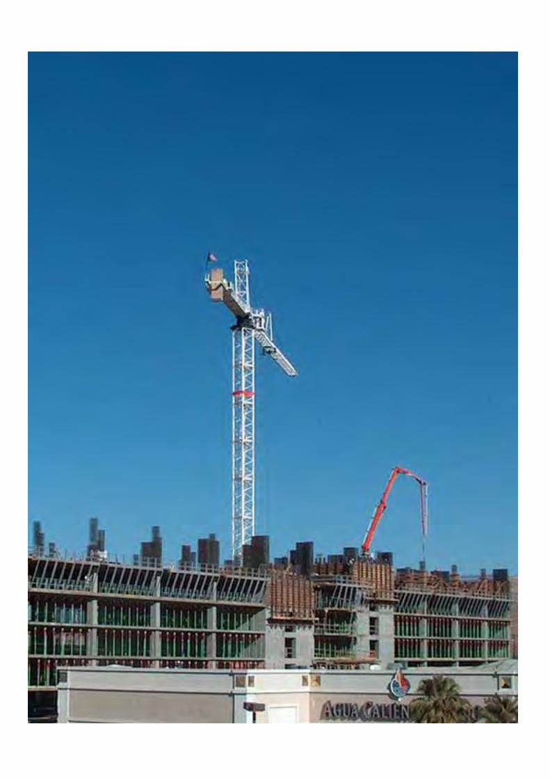
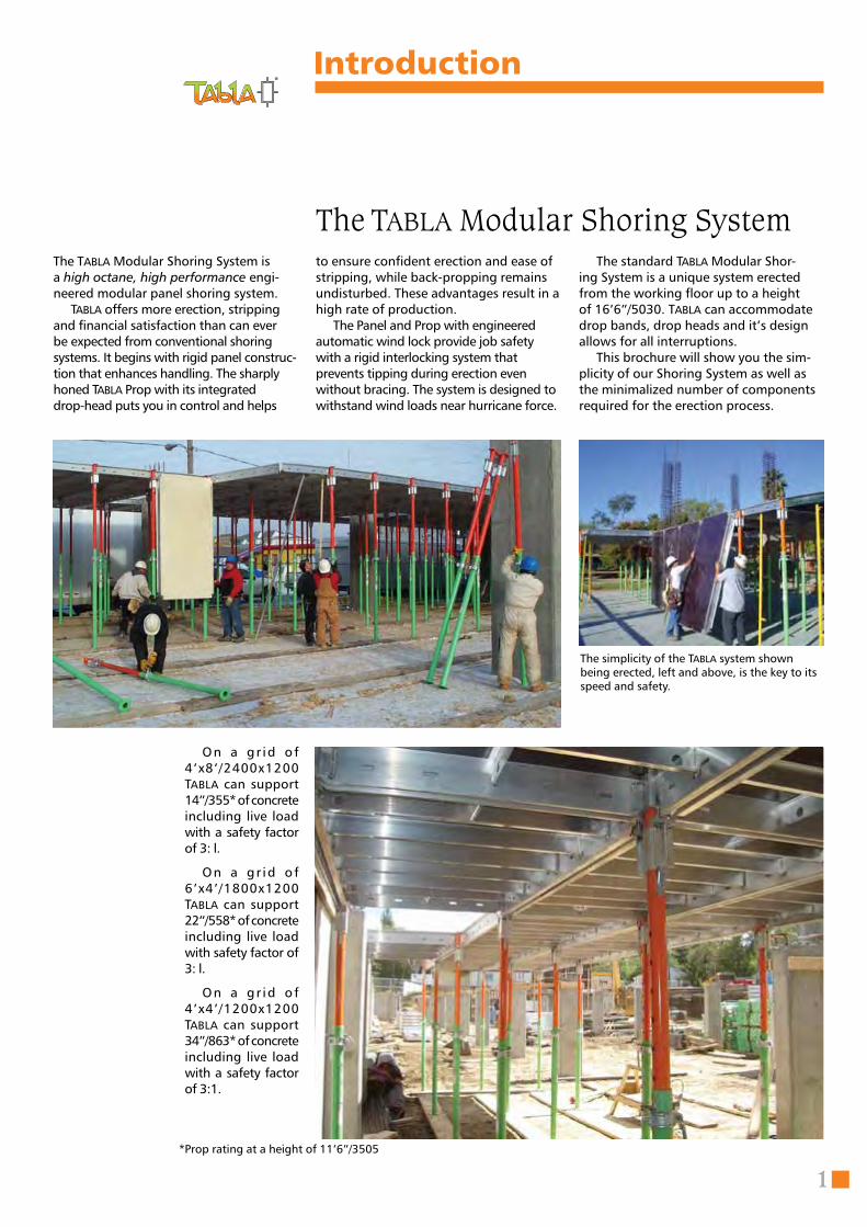
The Tabla Modular Shoring System is a high octane, high performance engi-neered modular panel shoring system. Tabla offers more erection, stripping and financial satisfaction than can ever be expected from conventional shoring systems. It begins with rigid panel construc-tion that enhances handling. The sharply honed Tabla Prop with its integrated drop-head puts you in control and helps
Introduction
The Tabla Modular Shoring Systemto ensure confident erection and ease of stripping, while back-propping remains undisturbed. These advantages result in a high rate of production. The Panel and Prop with engineered automatic wind lock provide job safety with a rigid interlocking system that prevents tipping during erection even without bracing. The system is designed to withstand wind loads near hurricane force.
*Prop rating at a height of 11’6”/3505
On a gr id o f 4’x8’/2400x1200 Tabla can support 14”/355* of concrete including live load with a safety factor of 3: l. On a gr id o f 6’x4’/1800x1200 Tabla can support 22”/558* of concrete including live load with safety factor of 3: l.
On a gr id o f 4’x4’/1200x1200 Tabla can support 34”/863* of concrete including live load with a safety factor of 3:1.
The simplicity of the Tabla system shown being erected, left and above, is the key to its speed and safety.
The standard Tabla Modular Shor-ing System is a unique system erected from the working floor up to a height of 16’6”/5030. Tabla can accommodate drop bands, drop heads and it’s design allows for all interruptions. This brochure will show you the sim-plicity of our Shoring System as well as the minimalized number of components required for the erection process.
1
3 ADT tool
1 Prop2 Panel
When I started the design of the Tabla Modular Shoring Sys-tem, safety was the first and most important criteria. The well being of the workers who clearly would trust us was paramount. To those workers, we promise that we will never employ anything less than a 3:1 safety factor under live condi-tions, regardless of economic pressures.
Another decisive factor was to create the most economical system in the world. Thousands of design and trial hours have made this a reality. We have kept the end operation simple and safe. Currently we have over 2 million square feet, or 180,000 square meters of Tabla in operation and have poured over 200 million square feet, or 18 million square meters of concrete in North America and Europe.
Our customers have consistently erected Tabla panels and props up to 12’/3658 high with 14”/356 thick slabs and 11’/3353 high with 16”/406 thick slabs, including backshor-ing and reshoring, at a rate that exceeds 300 square feet, or 28 square meters per m an hour. Additionally, panels have been removed at a rate that exceeds 600 square feet, or 56 square meters per man hour in less than 2 days curing time, with a vastly reduced crew.
We promise to continue to faithfully improve Tabla, see-ing to it that our system is always Fast, Safe and Efficient. We introduced the second generation of Tabla at the 2007 World of Concrete in Las Vegas along with giving a “sneak peak” of our New Quick-release Reshore and the world’s first KD (knocked down) panel.
Another future release will be an aluminum prop that will provide a height up to 22’/6706, and most importantly, in stant adjustment. This will eliminate the now accepted screw, common in the market place today.
There is much more on the drawing board in the Tabla Engineering Department , so stay tuned, but first let us tell you about the Tabla Modular Shoring System.
Introduction
With Tabla, the Future is Now!
2
Paul A. GillespieTabla Inventor & Founder
The Tabla Modular Shoring System is an engineered modular panel shoring system which offers faster erection and stripping time than conventional shor-ing systems, directly increases financial return.
The rigid construction of the Tabla Panel enhances handling and durability. The Tabla Prop, with its integrated Drop-head, ensures confident assembly and ease of stripping from the floor below, while backpropping remains undisturbed.
The automatic wind lock design of the Panel and Prop prevents tipping during erection. The Tabla Modular Shoring Sys-tem has resisted gale force wind loads.
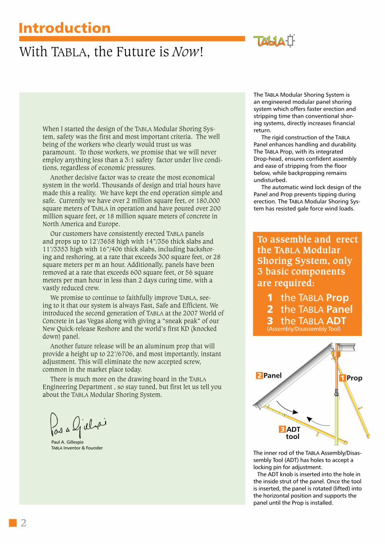
The inner rod of the Tabla Assembly/Disas-sembly Tool (ADT) has holes to accept a locking pin for adjustment.
The ADT knob is inserted into the hole in the inside strut of the panel. Once the tool is inserted, the panel is rotated (lifted) into the horizontal position and supports the panel until the Prop is installed.
To assemble and erect the Tabla ModularShoring System, only 3 basic components are required:
1 the Tabla Prop 2 the Tabla Panel 3 the Tabla ADT (Assembly/Disassembly Tool)
ADT toolProp
3
The Tabla System: Safe, Fast, Efficient
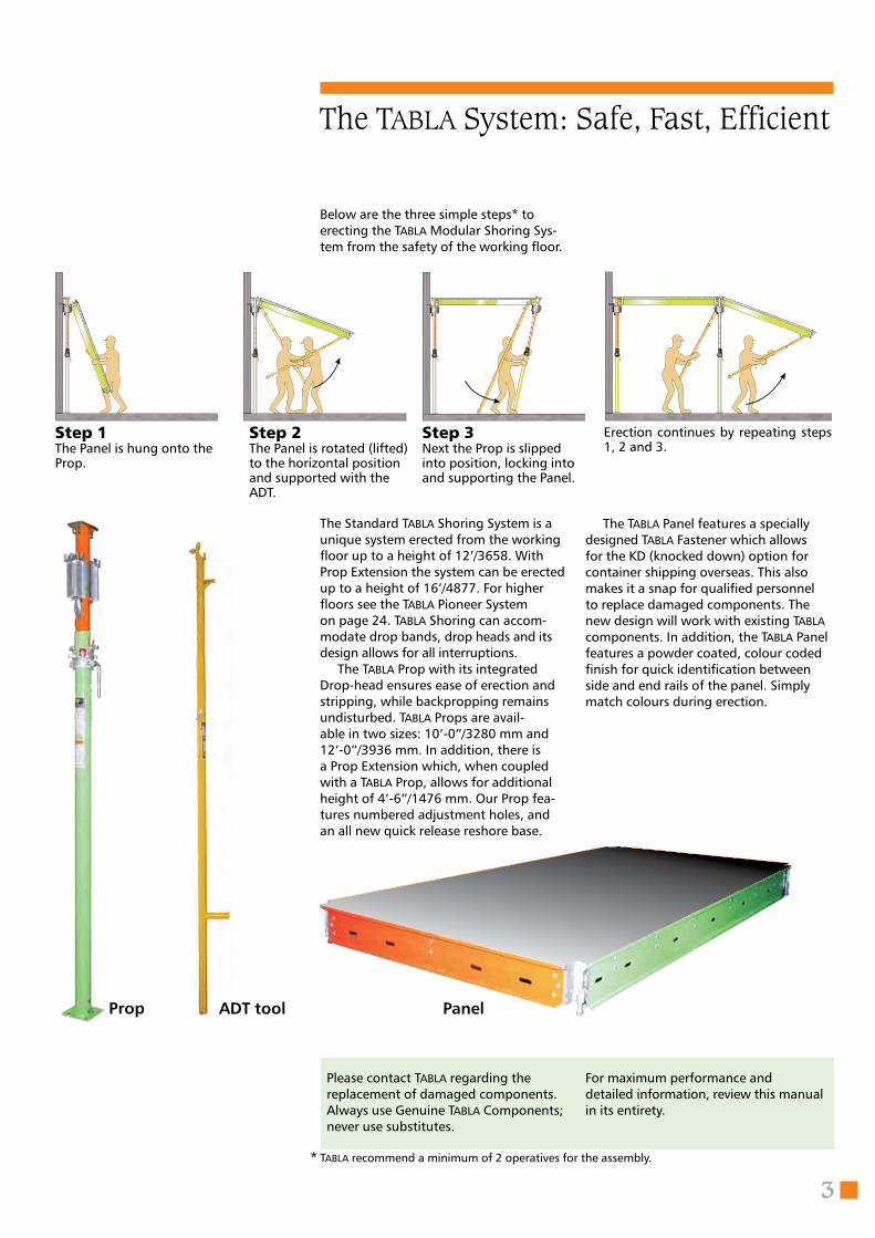
The Standard Tabla Shoring System is a unique system erected from the working floor up to a height of 12’/3658. With Prop Extension the system can be erected up to a height of 16’/4877. For higher floors see the Tabla Pioneer System on page 24. Tabla Shoring can accom-modate drop bands, drop heads and its design allows for all interruptions.
The Tabla Prop with its integrated Drop-head ensures ease of erection and stripping, while backpropping remains undisturbed. Tabla Props are avail-able in two sizes: 10’-0”/3280 mm and 12’-0”/3936 mm. In addition, there is a Prop Extension which, when coupled with a Tabla Prop, allows for additional height of 4’-6”/1476 mm. Our Prop fea-tures numbered adjustment holes, and an all new quick release reshore base.
Step 1 The Panel is hung onto the Prop.
Step 2 The Panel is rotated (lifted) to the horizontal position and supported with the ADT.
Step 3Next the Prop is slipped into position, locking into and supporting the Panel.
Erection continues by repeating steps 1, 2 and 3.
Panel
For maximum performance and detailed information, review this manual in its entirety.
Below are the three simple steps* to erecting the Tabla Modular Shoring Sys-tem from the safety of the working floor.
Please contact Tabla regarding the replacement of damaged components. Always use Genuine Tabla Components; never use substitutes.
The Tabla Panel features a specially designed Tabla Fastener which allows for the KD (knocked down) option for container shipping overseas. This also makes it a snap for qualified personnel to replace damaged components. The new design will work with existing Tabla components. In addition, the Tabla Panel features a powder coated, colour coded finish for quick identification between side and end rails of the panel. Simply match colours during erection.
* Tabla recommend a minimum of 2 operatives for the assembly.
4
Tabla Procedures
Erection
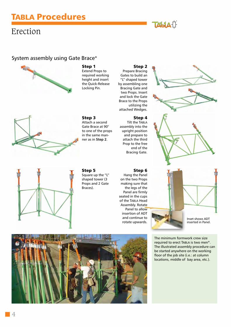
The minimum formwork crew size required to erect Tabla is two men*.The illustrated assembly procedure can be started anywhere on the working floor of the job site (i.e.: at column locations, middle of bay area, etc.).
Step 1Extend Props to required working height and insert the Quick-Release Locking Pin.
Step 2Prepare Bracing
Gates to build an “L” shaped tower
by assembling one Bracing Gate and two Props. Insert
and lock the Gate Brace to the Props
utilizing the attached Wedges.
Step 3 Attach a second Gate Brace at 90° to one of the props in the same man-ner as in Step 2.
Step 4 Tilt the Tabla
assembly into the upright position
and prepare to attach the third Prop to the free
end of the Bracing Gate.
Step 5 Square up the “L” shaped tower (3 Props and 2 Gate Braces).
Step 6 Hang the Panel
on the two Props making sure that
the legs of the Panel are firmly
seated in the cups of the Tabla Head Assembly. Rotate
Panel to allow insertion of ADT and continue to rotate upwards.
System assembly using Gate Brace*
Inset shows ADT inserted in Panel.
5
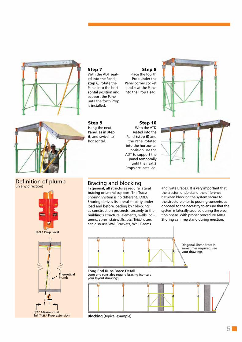
Step 7 With the ADT seat-ed into the Panel, step 6, rotate the Panel into the hori-zontal position and support the Panel until the forth Prop is installed.
Step 8 Place the fourth Prop under the
Panel corner socket and seat the Panel
into the Prop Head.
Step 10 With the ATD
seated into the Panel (step 6) and
the Panel rotated into the horizontal
position use the ADT to support the
panel temporaily until the next 2
Props are installed.
In general, all structures require lateral bracing or lateral support. The Tabla Shoring System is no different. Tabla Shoring derives its lateral stability under load and before loading by “blocking”, as construction proceeds, securely to the building’s structural elements, walls, col-umns, cores, stairwells, etc. Tabla users can also use Wall Brackets, Wall Beams
and Gate Braces. It is very important that the erector, understand the difference between blocking the system secure to the structure prior to pouring concrete, as opposed to the necessity to ensure that the system is laterally secured during the erec-tion phase. With proper procedure Tabla Shoring can free stand during erection.
Bracing and blocking
Diagonal Shear Brace is sometimes required, see your drawings
Long End Runs Brace Detail
Blocking (typical example)
Long end runs also require bracing (consult your layout drawings).
Definition of plumb(in any direction)
Tabla Prop Level
3/4” Maximum atfull Tabla Prop extension
Step 9 Hang the next Panel, as in step 6, and swivel to horizontal.
TheoreticalPlumb
6
Tabla Procedures
Stripping
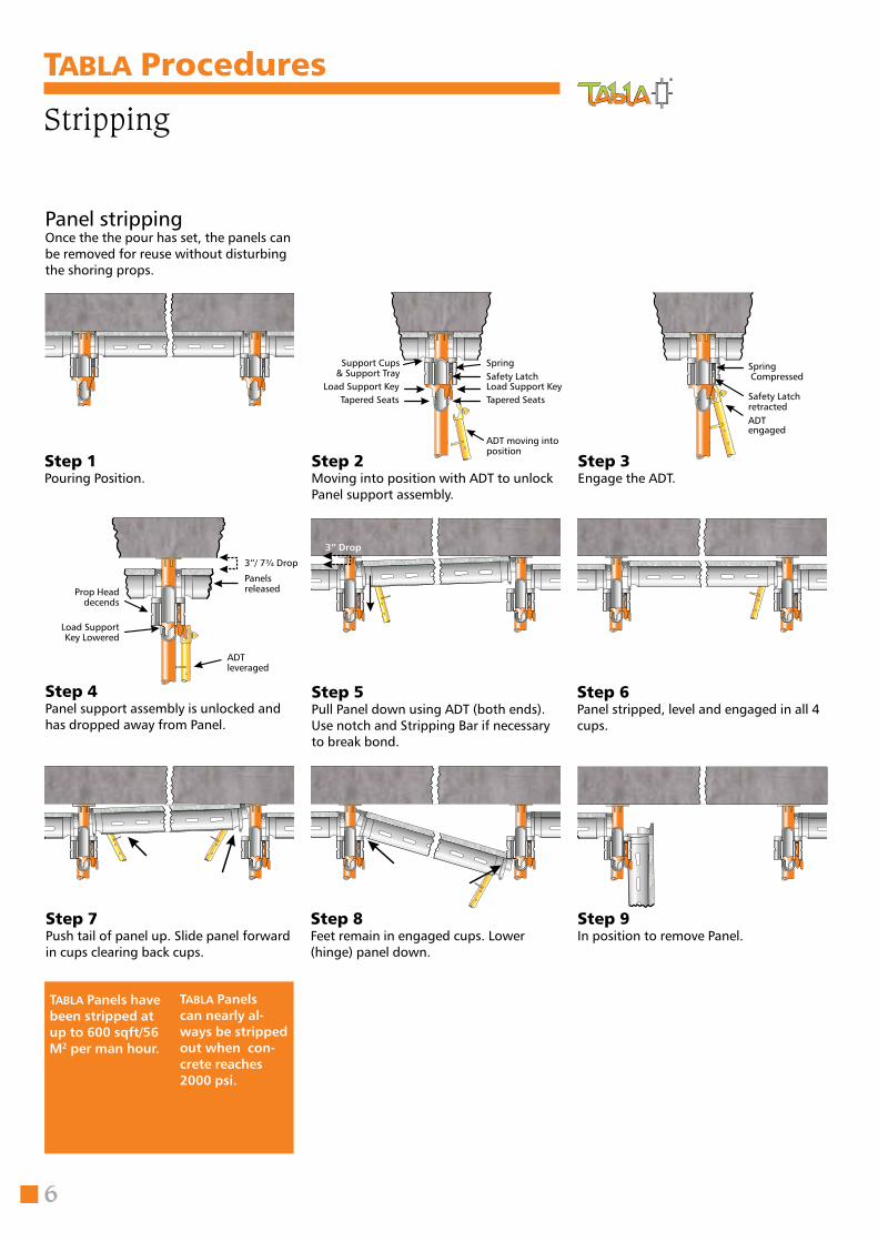
Step 1Pouring Position.
Step 5Pull Panel down using ADT (both ends).Use notch and Stripping Bar if necessary to break bond.
Step 6Panel stripped, level and engaged in all 4 cups.
Step 7Push tail of panel up. Slide panel forward in cups clearing back cups.
Step 8Feet remain in engaged cups. Lower (hinge) panel down.
Step 9In position to remove Panel.
Panel stripping
Tabla Panels have been stripped at up to 600 sqft/56 M2 per man hour.
Tabla Panelscan nearly al-ways be stripped out when con-crete reaches 2000 psi.
Once the the pour has set, the panels can be removed for reuse without disturbing the shoring props.
Step 2Moving into position with ADT to unlock Panel support assembly.
Step 3Engage the ADT.
Step 4Panel support assembly is unlocked and has dropped away from Panel.
Support Cups& Support Tray
Load Support KeyTapered Seats Tapered Seats
Load Support KeySafety LatchSpring
ADT moving into position
Spring Compressed
Safety Latch retractedADTengaged
ADT leveraged
Panelsreleased
3”/ 7¾ Drop
Prop Head decends
Load Support Key Lowered
3” Drop
7
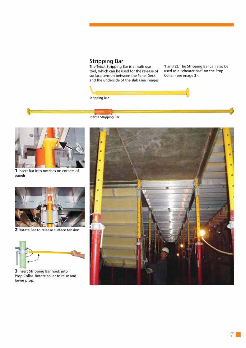
The Tabla Stripping Bar is a multi use tool, which can be used for the release of surface tension between the Panel Deck and the underside of the slab (see images
1 Insert Bar into notches on corners of panels.
2 Rotate Bar to release surface tension.
3 Insert Stripping Bar hook intoProp Collar. Rotate collar to raise and lower prop.
Stripping Bar.
Stripping Bar1 and 2). The Stripping Bar can also be used as a “cheater bar” on the Prop Collar. (see image 3).
Inertia Stripping Bar
8
Tabla Procedures
Shoring, Backshoring and Reshoring
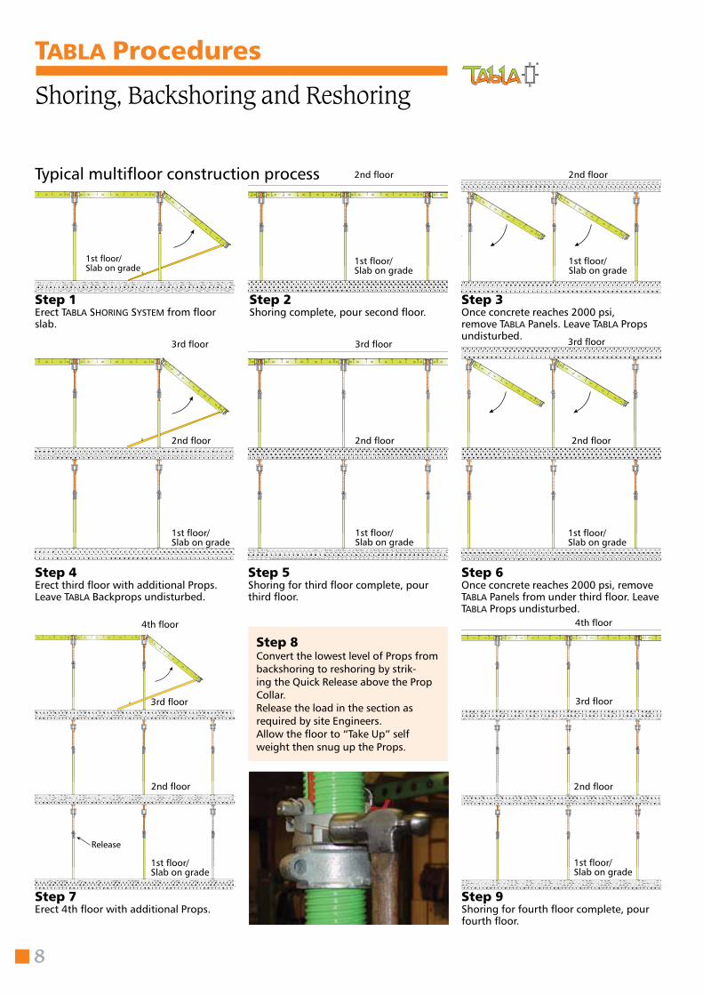
Step 1Erect Tabla Shoring SyStem from floor slab.
1st floor/Slab on grade
Step 2Shoring complete, pour second floor.
1st floor/Slab on grade
2nd floor
Step 3Once concrete reaches 2000 psi, remove Tabla Panels. Leave Tabla Props undisturbed.
1st floor/Slab on grade
2nd floor
Step 4Erect third floor with additional Props.Leave Tabla Backprops undisturbed.
1st floor/Slab on grade
2nd floor
3rd floor
Step 6Once concrete reaches 2000 psi, remove Tabla Panels from under third floor. Leave Tabla Props undisturbed.
Step 5Shoring for third floor complete, pour third floor.
1st floor/Slab on grade
2nd floor
3rd floor
1st floor/Slab on grade
3rd floor
Step 8Convert the lowest level of Props from backshoring to reshoring by strik-ing the Quick Release above the Prop Collar.Release the load in the section as required by site Engineers.Allow the floor to “Take Up” self weight then snug up the Props.
Step 7Erect 4th floor with additional Props.
Step 9Shoring for fourth floor complete, pour fourth floor.
1st floor/Slab on grade
2nd floor
3rd floor
4th floor
1st floor/Slab on grade
2nd floor
3rd floor
4th floor
2nd floor
Typical multifloor construction process
Release
Ready to strike.Releasing the Safety Clip.
Hitting the striker. Released position.
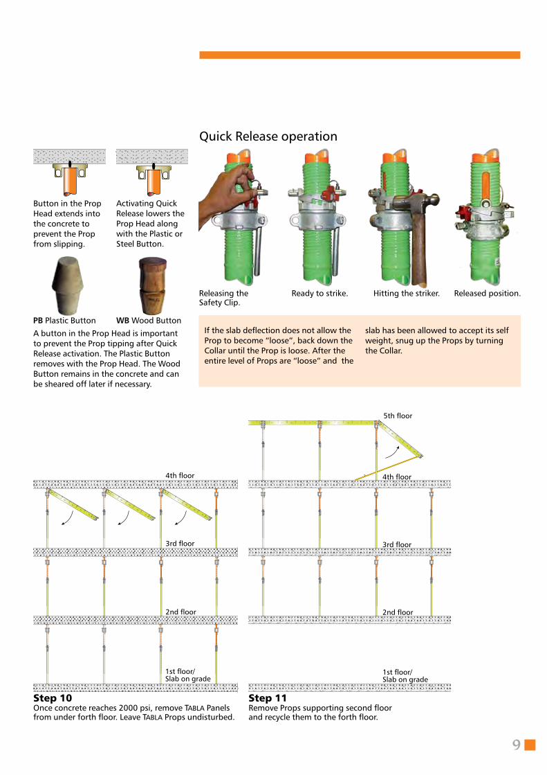
Step 11Remove Props supporting second floor and recycle them to the forth floor.
9
Step 10Once concrete reaches 2000 psi, remove Tabla Panels from under forth floor. Leave Tabla Props undisturbed.
1st floor/Slab on grade
2nd floor
3rd floor
4th floor
1st floor/Slab on grade
2nd floor
3rd floor
4th floor
5th floor
PB Plastic Button
A button in the Prop Head is important to prevent the Prop tipping after Quick Release activation. The Plastic Button removes with the Prop Head. The Wood Button remains in the concrete and can be sheared off later if necessary.
WB Wood Button
Button in the Prop Head extends into the concrete to pre vent the Prop from slipping.
Activating Quick Release lowers the Prop Head along with the Plastic or Steel Button.
If the slab deflection does not allow the Prop to become “loose”, back down the Collar until the Prop is loose. After the entire level of Props are “loose” and the
Quick Release operation
slab has been allowed to accept its self weight, snug up the Props by turning the Collar.
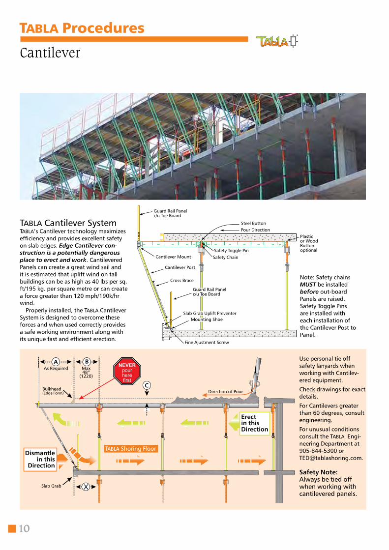
Cantilever
10
Tabla Cantilever SystemTabla’s Cantilever technology maximizes efficiency and provides excellent safety on slab edges. Edge Cantilever con-struction is a potentially dangerous place to erect and work. Cantilevered Panels can create a great wind sail and it is estimated that uplift wind on tall buildings can be as high as 40 lbs per sq. ft/195 kg. per square metre or can create a force greater than 120 mph/190k/hr wind. Properly installed, the Tabla Cantilever System is designed to overcome these forces and when used correctly provides a safe working environment along with its unique fast and efficient erection.
Tabla Procedures
Use personal tie off safety lanyards when working with Cantilev-ered equipment.
Check drawings for exact details.
For Cantilevers greater than 60 degrees, consult engineering.
For unusual conditions consult the Tabla Engi-neering Department at 905-844-5300 [email protected].
Safety Note: Always be tied off when working with cantilevered panels.
Guard Rail Panelc/u Toe Board
Pour DirectionSteel Button
Plastic or Wood Button optionalSafety Toggle Pin
Safety Chain
Guard Rail Panelc/u Toe Board
Cantilever Mount
Cantilever Post
Cross Brace
Slab Grab Uplift PreventerMounting Shoe
Fine Ajustment Screw
Direction of PourC
BA
Bulkhead(Edge Form)
As Required Max48”
(1220)
Tabla Shoring FloorDismantle
in this Direction
Erectin this Direction
Slab Grab
Note: Safety chains MUST be installed before out-board Panels are raised.Safety Toggle Pins are installed with each installation of the Cantilever Post to Panel.
11
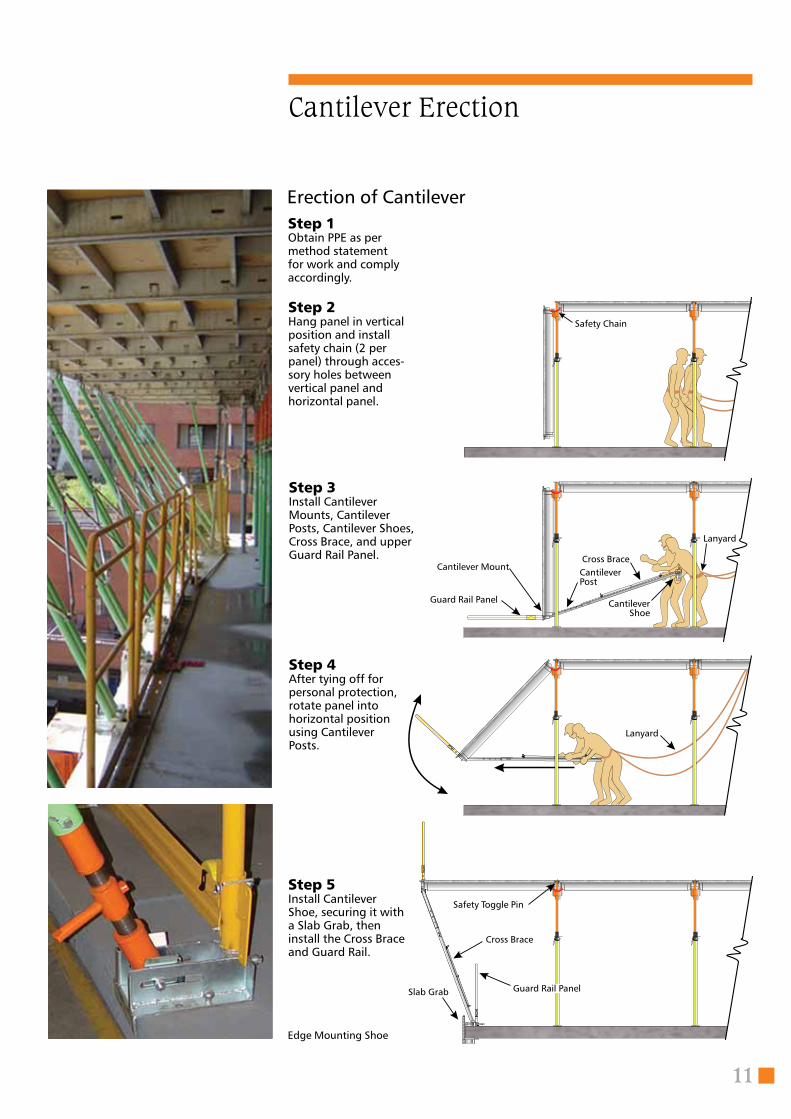
Step 1 Obtain PPE as per method statement for work and comply accordingly.
Step 3 Install Cantilever Mounts, Cantilever Posts, Cantilever Shoes, Cross Brace, and upper Guard Rail Panel.
Step 4 After tying off for personal protection, rotate panel into horizontal position using Cantilever Posts.
Step 5 Install Cantilever Shoe, securing it with a Slab Grab, then install the Cross Brace and Guard Rail.
Erection of Cantilever
Edge Mounting Shoe
Step 2 Hang panel in vertical position and install safety chain (2 per panel) through acces-sory holes between vertical panel and horizontal panel.
CantileverShoe
CantileverPost
Cantilever Mount
Safety Toggle Pin
Slab Grab Guard Rail Panel
Lanyard
Cross Brace
Guard Rail Panel
Safety Chain
Lanyard
Cantilever Erection
Cross Brace
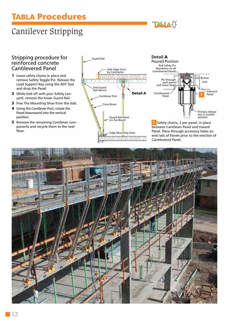
Tabla Procedures
Cantilever Stripping
12
Detail A Poured Position
Guard Rail
Slab Edge Formby Contractor
End Guard Rail Mount
Cantilever Post
Cross Brace
Edge Mounting Shoe
1 Leave safety chains in place and remove Safety Toggle Pin. Release the Load Support Key using the ADT Tool and drop the Panel.
2 While tied off with your Safety Lan-yard, remove the lower Guard Rail.
3 Free The Mounting Shoe from the slab.4 Using the Cantilever Post, rotate the
Panel downward into the vertical position.
5 Remove the remaining Cantilever com-ponents and recycle them to the next floor.
Stripping procedure for reinforced concrete Cantilevered Panel
Pin througheach panel
and Shear Head
Cantilevered Panel
Steel Button
InboundPanel
Primary release key in Locked position
1
Red Safety Pin Manditory on all
Cantilevered Panels
1 Safety chains, 2 per panel, in place between Cantilever Panel and Inward Panel. Place through accessory holes on end rails of Panels prior to the erection of Cantilevered Panel.
Guard Rail Panelc/u Toe Board
Detail A
13
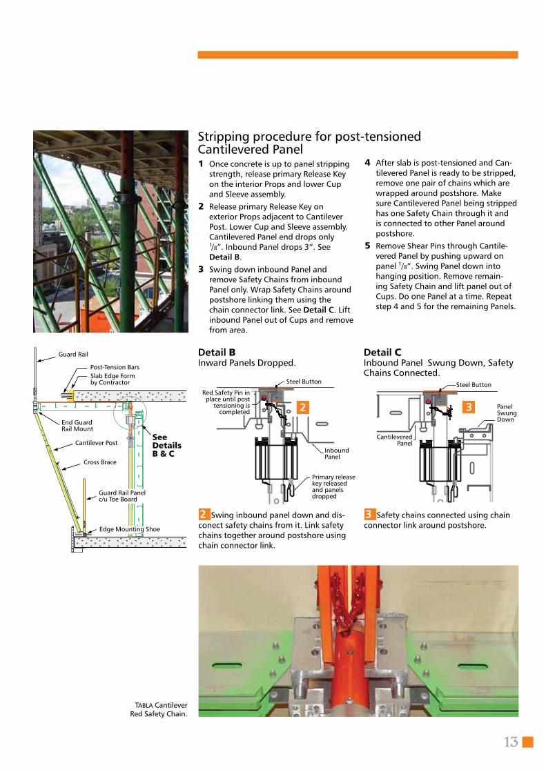
Tabla CantileverRed Safety Chain.
Detail BInward Panels Dropped.
2 Swing inbound panel down and dis-conect safety chains from it. Link safety chains together around postshore using chain connector link.
Detail CInbound Panel Swung Down, Safety Chains Connected.
3 Safety chains connected using chain connector link around postshore.
Inbound Panel
Steel Button
2
Primary release key released and panels dropped
Red Safety Pin in place until post
tensioning is completed
Cantilevered Panel
Steel Button
3 Panel Swung Down
Post-Tension Bars
4 After slab is post-tensioned and Can-tilevered Panel is ready to be stripped, remove one pair of chains which are wrapped around postshore. Make sure Cantilevered Panel being stripped has one Safety Chain through it and is connected to other Panel around postshore.
5 Remove Shear Pins through Cantile-vered Panel by pushing upward on panel 1/8”. Swing Panel down into hanging position. Remove remain-ing Safety Chain and lift panel out of Cups. Do one Panel at a time. Repeat step 4 and 5 for the remaining Panels.
1 Once concrete is up to panel stripping strength, release primary Release Key on the interior Props and lower Cup and Sleeve assembly.
2 Release primary Release Key on exterior Props adjacent to Cantilever Post. Lower Cup and Sleeve assembly. Cantilevered Panel end drops only 1/8”. Inbound Panel drops 3”. See Detail B.
3 Swing down inbound Panel and remove Safety Chains from inbound Panel only. Wrap Safety Chains around postshore linking them using the chain connector link. See Detail C. Lift inbound Panel out of Cups and remove from area.
Stripping procedure for post-tensionedCantilevered Panel
Guard Rail
Slab Edge Formby Contractor
See DetailsB & C
End Guard Rail Mount
Cantilever Post
Cross Brace
Edge Mounting Shoe
Guard Rail Panelc/u Toe Board
14
Tabla Procedures
Ramps
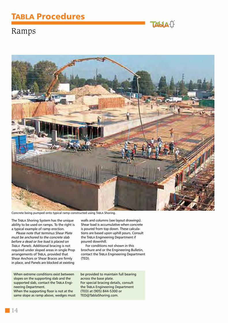
The Tabla Shoring System has the unique ability to be used on ramps. To the right is a typical example of ramp erection.
Please note that terminus Shear Plate must be anchored to the concrete slab before a dead or live load is placed on Tabla Panels. Additional bracing is not required under sloped areas in single Prop arrangements of Tabla, provided that Shear Anchors or Shear Braces are firmly in place, and Panels are blocked at existing
walls and columns (see layout drawings). Shear load is accumulative when concrete is poured from top down. These calcula-tions are based upon uphill pours. Consult the Tabla Engineering Department if poured downhill.
For conditions not shown in this brochure and or the Engineering Bulletin, contact the Tabla Engineering Department (TED).
Concrete being pumped onto typical ramp constructed using Tabla Shoring.
When extreme conditions exist between slopes on the supporting slab and the supported slab, contact the Tabla Engi-neering Department.When the supporting floor is not at the same slope as ramp above, wedges must
be provided to maintain full bearing across the base plate.For special bracing details, consult the Tabla Engineering Department (TED) at (905) 844-5300 or [email protected].
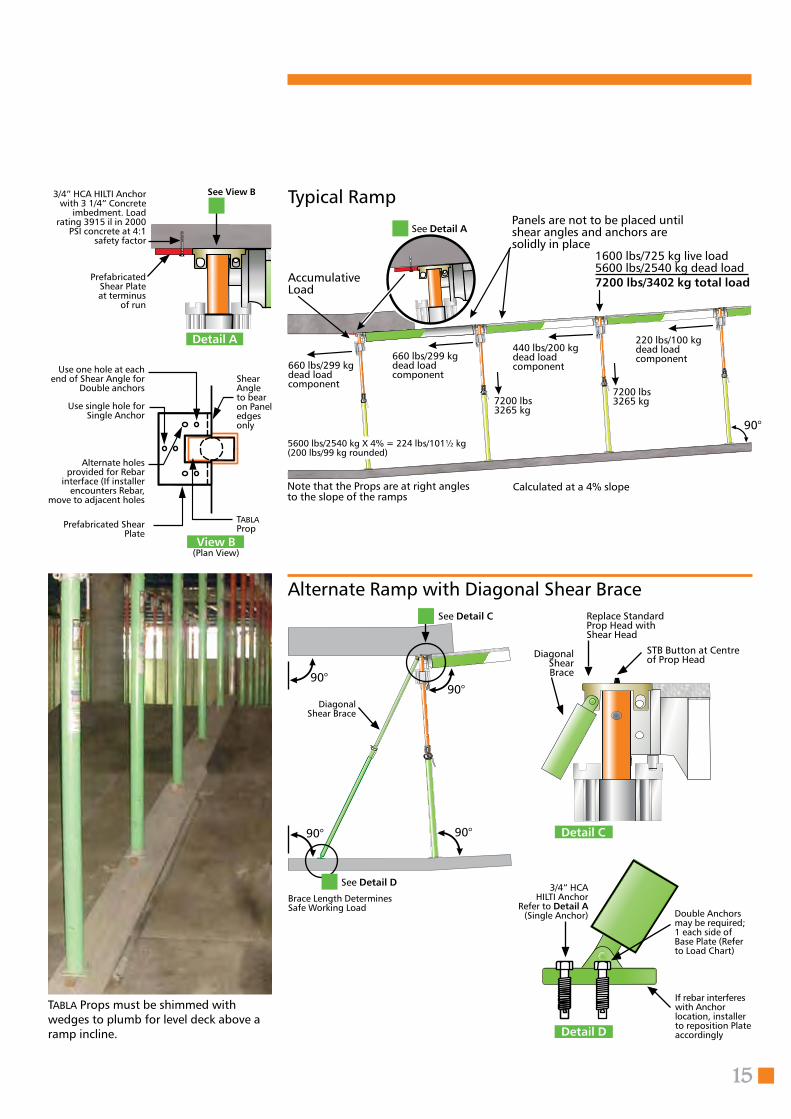
Brace Length Determines Safe Working Load
90°90°
90°90°
15
Typical Ramp3/4” HCA HILTI Anchor with 3 1/4” Concrete
imbedment. Load rating 3915 il in 2000
PSI concrete at 4:1 safety factor
See View B
Alternate holes provided for Rebar
interface (If installer encounters Rebar,
move to adjacent holes
Shear Angle to bear on Panel edges only
Use one hole at each end of Shear Angle for
Double anchors
Use single hole for Single Anchor
Tabla PropPrefabricated Shear
Plate
See Detail C
3/4” HCAHILTI Anchor
Refer to Detail A (Single Anchor) Double Anchors
may be required;1 each side of Base Plate (Refer to Load Chart)
STB Button at Centre of Prop Head
Alternate Ramp with Diagonal Shear BraceReplace Standard Prop Head with Shear Head
Prefabricated Shear Plate at terminus
of run
See Detail D
Detail A
View B(Plan View)
660 lbs/299 kg dead load component
7200 lbs3265 kg
Panels are not to be placed until shear angles and anchors are solidly in place
AccumulativeLoad
1600 lbs/725 kg live load5600 lbs/2540 kg dead load7200 lbs/3402 kg total load
660 lbs/299 kg dead load component
440 lbs/200 kg dead load component
220 lbs/100 kg dead load component
7200 lbs3265 kg
Note that the Props are at right angles to the slope of the ramps
Calculated at a 4% slope
5600 lbs/2540 kg X 4% = 224 lbs/101½ kg (200 lbs/99 kg rounded)
90°
See Detail A
If rebar interferes with Anchor location, installer to reposition Plate accordingly
Diagonal Shear Brace
Diagonal Shear Brace
Detail D
Detail C
Tabla Props must be shimmed with wedges to plumb for level deck above a ramp incline.
Tabla Pioneer is a high floor shoring system which allows you to go to any height (subject to shoring tower specifi-cations). It can be erected using Tabla’s Pioneer Head Assembly (Detail 1) or Tabla Prop (Detail 2). Either configura-tion can be attached to most standard shoring frames using Tabla’s Pioneer Connector. The system allows for strip-ping of the Panels while backshoring
High Floor Shoring System
16
Tabla Procedures
Tabla Pioneer System
remains undisturbed. The new Tabla Quick Release Reshore Base (Detail 3) attaches to most screw-jacks using Tabla’s Pioneer Screw Adaptor. This allows the system to provide shor-ing, backshoring and reshoring using the same principal as Tabla’s Standard Shoring System. See pages 8 and 9 for more information regarding Backshoring and Reshoring.
Consult Tabla’s Engineering Department for more information Tabla Pioneer.
Erection1 Erect shoring towers using Tabla Panel
spacing2 Remove Head Plate from Pioneer Head
Assembly or Tabla Prop3 Connect Pioneer Head Assembly or
Tabla Prop to top of shoring frames
4 Drop Tabla Panels into position from above, snap in Tabla Prop Heads, then pour the floor
5 Once concrete reaches 2000 psi, and in accordance with ACI, strip Tabla Panels
Note: Tabla advise the use of a safeaccess system for this work.
Detail 3Tabla Quick Release Reshore Base
Shown with Pioneer Head Assembly (see Detail 1)
Shown with the Tabla Prop (see Detail 2)
Detail 1Pioneer Head Assembly
17
Detail 2Tabla Prop
Tabla Procedures
Infill components
Side Filler Beam
End Filler Beam
Gravity Lock
*Colours are reversed for metric sizes.
Tabla Infill CompomentsTabla infill Components are designed to bridge between Panels or between Panels, walls and columns.
18
Construction workers are using Side and End Filler Beams along with the Telescopic Beam they are holding to infill around a column at a project in Biola.
Side and End Filler BeamsSide and End Filler Beams allow 3/4” plywood to infill to the side of the Panel. The benefits of using Side and End Filler Beams are :
• Provide nailer strip for connecting 3/4” plywood;
• Eliminates notching of plywood around Post Shore Heads;
• Eliminates eccentric loading on Prop;
• Colour coded* for quick identification between Side and End Rails of Panels – simply match colours during erection.
Place the Filler Beam into the Prop Cup and secure it using the Tabla Gravity Lock through accessory holes of the Panel and Filler Beam.
DO
N
OT
OVER TIG
HTEN
19
Telescopic BeamsTabla Telescopic Beams are light weight and have an excellent load capacity. They are designed to take Drop Heads and Infil Strips from 3’0”/914 to 10’0”/3050. Telescopic Beams connect directly to the Filler Beams. These Beams are equipped with a graduated Bearing Plate at each end. Each Bearing Plate consists of 5 gravity bearing seats in 1” increments. By using the lowest seat the Tabla Telescopic Beam forms a flush deck using 3/4”/19mm plywood infill. Other levels are for change in slab thickness and Drop Heads.
Telescopic Beam
A-1 SignaturePost Shorewith U-Head
Supplemental SupportIn cases where the load or the drawing requires for “supplemental support”, the recommended procedure is as illustrated. At all times make sure that when install-ing the supplemental supports they do NOT lift the gravity seats out of the edge support.
For deeper drops of the Telescopic Beam use the Telescopic Beam Extension.
Use Telescopic Beam Hanger to connect to wall or column ledger.
Do not over tighten post shore & lift up formwork.Carpentry formwork by Contractor.Check drawings for exact details.Telescopic Beams may need supplemental supports.Always refer to Engineering drawings for the Telescopic Beam spacing and supports.Beam Extension
Beam Hanger
Telescopic Beams
Telescopic Beam supported atmid-span with “U-Head” Post Shore.
20
ABS Strip Option B
ABS Strip B design profile
ABS Strip Option A
ABS Strip A design profile
Architectural Bridge Strips
The Architectural Bridge Strips are pre-cut specifically designed plastic strips, which are inserted between the Tabla Panel joints to limit concrete seepage. Tabla offers two types of ABS strips which allow you to decide what type of ceiling finish you desire. Option B and option A are inserted between the panels by foot after erecting the panels prior to rebar. The ABS is colour coded for quick iden-tification between Side and End Rails of Panels. Simply match colours to install.
In California, U.S.A., this ceiling finish (see option A image) is desired in garages by contractors, architects and owners. The concrete contractor has little to do to the ceiling after removing the Tabla Panels and Props exposing a symmetrical ceiling finish. The indentation is less than 1/16” deep and if desired can be covered with a skim coat over the recess.
Detail of ABS Option A ceiling impression.
Laying colour coded strips between panels.
System ready for pour.
Tabla Procedures
21
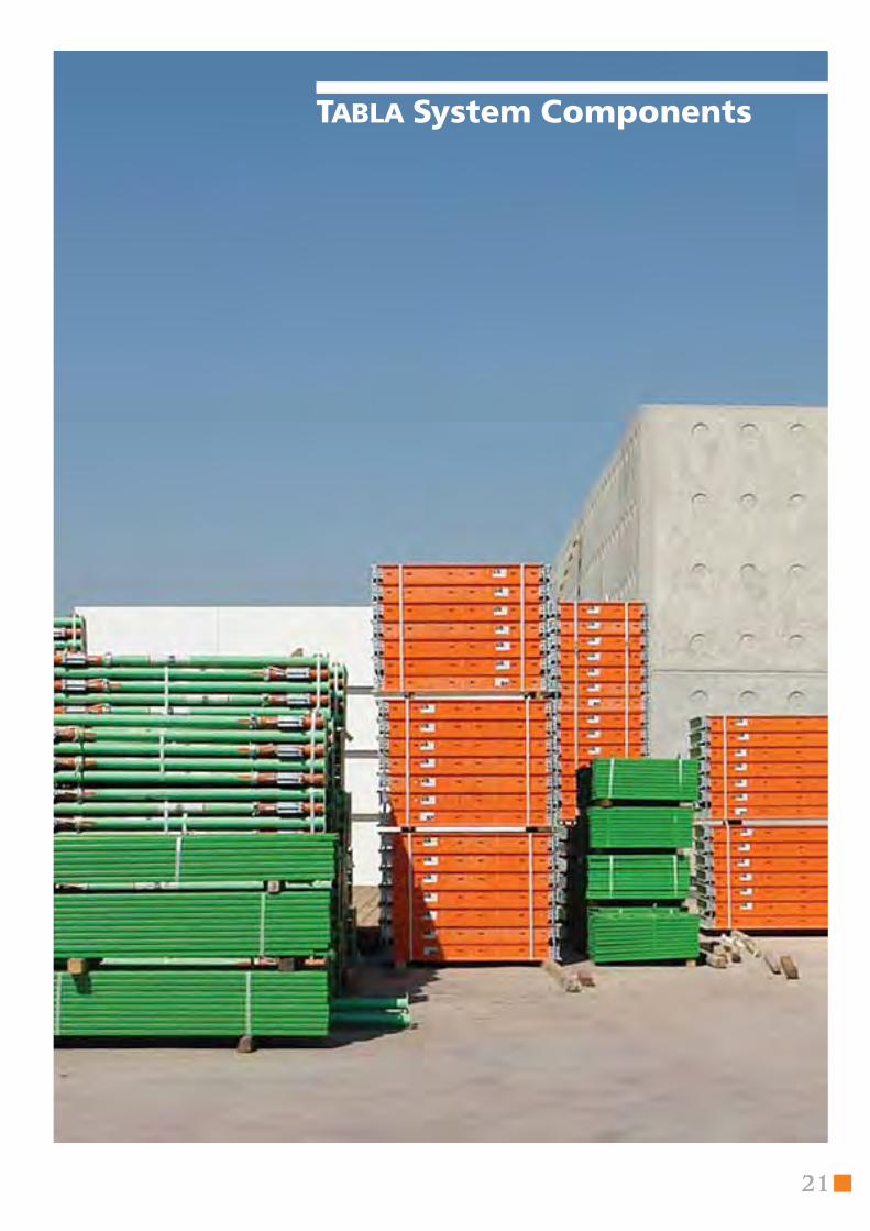
Tabla System Components
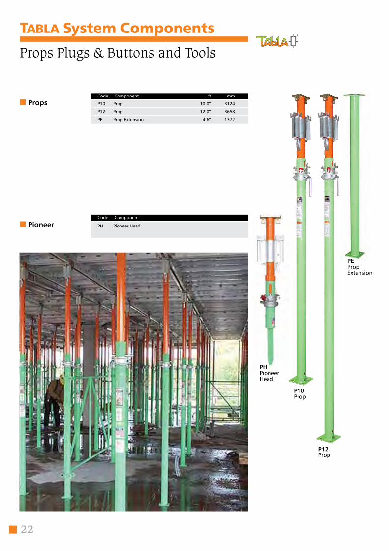
Tabla System Components
Props
Pioneer
Code Component ft | mm
P10 Prop 10’0” | 3124
P12 Prop 12’0” | 3658
PE Prop Extension 4’6” | 1372
PH Pioneer Head
Code Component
Props Plugs & Buttons and Tools
P12 Prop
PE PropExtension
22
PH Pioneer Head
P10 Prop
Plugs & Buttons PP Plastic Plug per 2000
PB Plastic Button per 2000 (default)
WB Wood Button per 2000
STB Steel Button per 250
ADT Assembly and Disassembly Tool
ADTLH Long Handle for ADT
SB Stripping Bar
ISB Inertia Stripping Bar
PB Plastic Button
WB WoodButton
PP Plastic Plug
SBStripping Bar
Code Component
Code Component
STBSteelButton
PP is used on Prop Top Plate when a But-ton is not required.PB is used on Prop Top Plate for Reshore – it is recoverable.WD is used on Prop Top Plate for Reshore – shear off protrusion.WS is used on Prop Top Plate for securing Cantillever – it is recoverable .
23
Plugs & Buttons and Tools
ADT Assemblyand Disassembly Tool
Tools
ISB InertiaStripping Bar
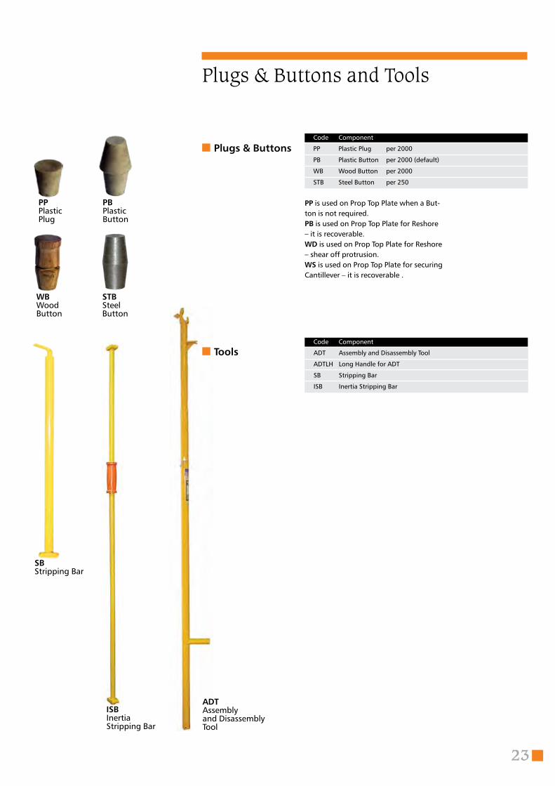
P44
P64
P84
P1212
P1812
P2412
24
P42 Panel 4x2
P62 Panel 6x2
P82 Panel 8x2
P44 Panel 4x4
P64 Panel 6x4
P84 Panel 8x4
Code Component ft
American Plywood Panels
Tabla System Components
Panel surface options
P126 Panel 1200x600
P186 Panel 1800x600
P246 Panel 2400x600
P1212 Panel 1200x1200
P1812 Panel 1800x1200
P2412 Panel 2400x1200
Code Component mm
American Plywood Metric Panels
P42P Panel 4x2
P62P Panel 6x2
P82P Panel 8x2
P44P Panel 4x4
P64P Panel 6x4
P84P Panel 8x4
Code Component ft
MCO®-Faced Plywood Panels
P126P Panel 1200x600
P186P Panel 1800x600
P246P Panel 2400x600
P1212P Panel 1200x1200
P1812P Panel 1800x1200
P2412P Panel 2400x1200
Code Component mm
MCO®-Faced Plywood Metric Panels
P42C Panel 4x2
P62C Panel 6x2
P82C Panel 8x2
P44C Panel 4x4
P64C Panel 6x4
P84C Panel 8x4
Code Component ft
MCO®-Faced Futura Light Weight Panels
P126C Panel 1200x600
P186C Panel 1800x600
P246C Panel 2400x600
P1212C Panel 1200x1200
P1812C Panel 1800x1200
P2412C Panel 2400x1200
Code Component mm
Metric Futura Light Weight Metric Panels
Micro®-Faced Futura™ Light Weight PanelsThese Light weight panels replace the plywood substrates and significantly reduce weight while improving durability.
Micro®-Faced Plywood PanelsThese panels are MCO™ Factory-laminated onto structurally rated plywood, edge-sealed and with a moisture-barrier back.
25
MCO®-Faced Futura Light Weight Transition Panels
TP64R
TP1812R
TP44C Transition Panel 4x4
TP84C Transition Panel 8x4
TP64CL Transition Panel Left Hand 6x4
TP64CR Transition Panel Right Hand 6x4
Code Component ft
MCO®-Faced Futura Light Weight Transition Metric Panels
TP1212C Transition Panel 1200x1200
TP2412C Transition Panel 2400x1200
TP1812CL Transition Panel Left Hand 1800x1200
TP1812CR Transition Panel Right Hand 1800x1200
Code Component mm
Panels
MCO®-Faced Plywood Transition Panels
TP44P Transition Panel 4x4
TP84P Transition Panel 8x4
TP64PL Transition Panel Left Hand 6x4
TP64PR Transition Panel Right Hand 6x4
Code Component ft
MCO®-Faced Plywood Transition Metric Panels
TP1212P Transition Panel 1200x1200
TP2412P Transition Panel 2400x1200
TP1812PL Transition Panel Left Hand 1800x1200
TP1812PR Transition Panel Right Hand 1800x1200
Code Component mm
American Plywood Transition Panels
TP44 Transition Panel 4x4
TP84 Transition Panel 8x4
TP64L Transition Panel Left Hand 6x4
TP64R Transition Panel Right Hand 6x4
Code Component ft
American Plywood Transition Metric Panels
TP1212 Transition Panel 1200x1200
TP2412 Transition Panel 2400x1200
TP1812L Transition Panel Left Hand 1800x1200
TP1812R Transition Panel Right Hand 1800x1200
Code Component mm
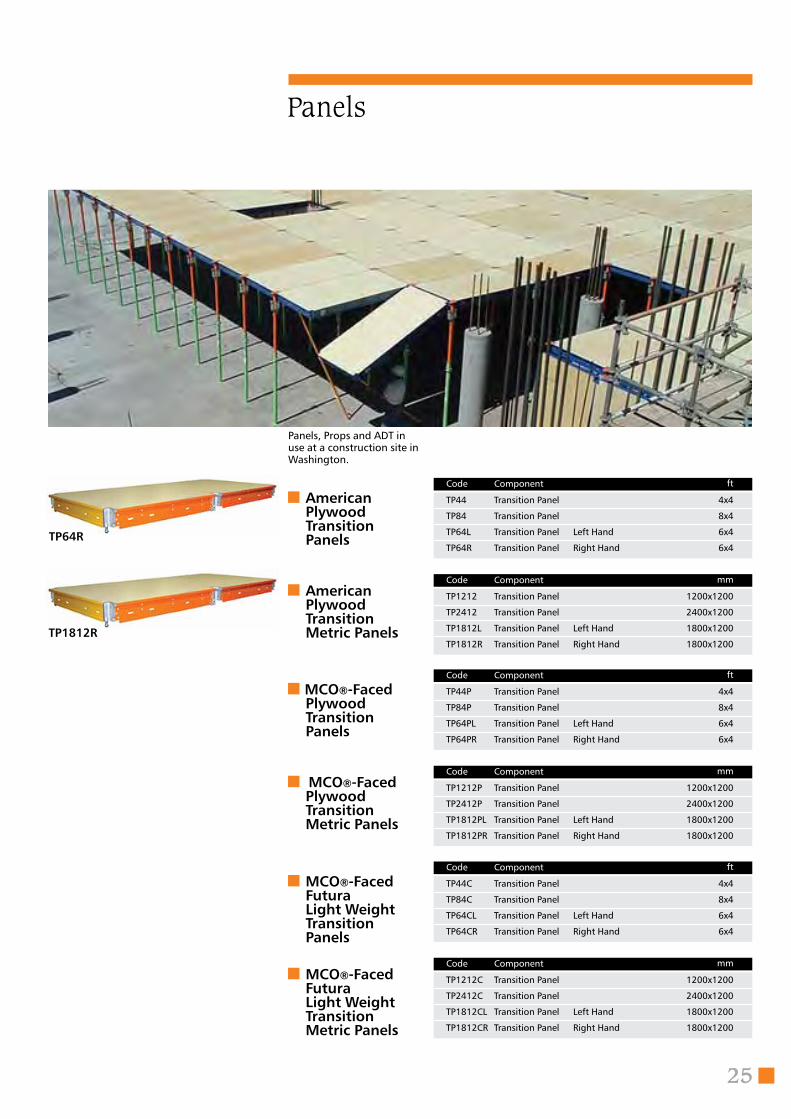
Panels, Props and ADT in use at a construction site in Washington.
26
Tabla System Components
Beams and Hangers
EF2 End Filler 2
EF4 End Filler 4
SF4 Side Filler 4
SF6 Side Filler 6
SF8 Side Filler 8
FB2x4 Filler Bracket 2x4 3 Way
UGL Universal Gravity Lock
Code Component ft
Filler Beams
EF6 End Filler 600
EF12 End Filler 1200
SF12 Side Filler 1200
SF18 Side Filler 1800
SF24 Side Filler 2400
FB2x4M Filler Bracket 2x4 3 Way
UGL Universal Gravity Lock
Code Component mm
Metric Filler Beams
TSB3 Telescopic Beam 3
TSB5 Telescopic Beam 5
TSB10 Telescopic Beam 10
Code Component ft
Telescopic Beams
TSB3 Telescopic Beam 914
TSB5 Telescopic Beam 1524
TSB10 Telescopic Beam 3048
Code Component mm
Metric Telescopic Beams
TSB3S Swivel Telescopic Beam 3
TSB5S Swivel Telescopic Beam 5
TSB10S Swivel Telescopic Beam 10
Code Component ft
Swivel Telescopic Beams
TSB3S Swivel Telescopic Beam 914
TSB5S Swivel Telescopic Beam 1524
TSB10S Swivel Telescopic Beam 3048
Code Component mm
Metric Swivel Telescopic Beams
TBH Telescopic Beam Hanger
Code Component
TBDE Telescopic Beam Drop Extension
Code Component
FB 2x4Filler Bracket 2x4 3-way
UGLUniversal Gravity Lock
Telescopic Beam Hanger
Telescopic Beam Drop Extension
EF4End Filler Beam
SF4Side Filler Beam
SF12Metric Side Filler Beam
TSB5Telescopic Beam
TBHTelescopicBeam Hanger
EF12Metric End Filler Beam
TSB5SSwivel Telescopic Beam
27
Cantilever, Guard Rail & Postand Gate Brace
CP Cantilever Post
CPE Cantilever Post Extension
EMS Edge Mounting Shoe
SGR Slab Grab
EPC End Panel Connector
SPC Side Panel Connector
Code Component
Cantilever
GRP Guard Rail Post 4.5
GR4 Guard Rail Panel 4.0
GR6 Guard Rail Panel 6.0
GR8 Guard Rail Panel 8.0
GRPC Guard Rail Post Connector
Code Component ft
Guard Rail Panel and Post
GRP Guard Rail Post 1372
GR12 Guard Rail Panel 1200
GR18 Guard Rail Panel 1800
GR24 Guard Rail Panel 2400
GRPC Guard Rail Post Connector
Code Component mm
Metric Guard Rail Panel and Post
GB4 Gate Brace 4
GB6 Gate Brace 6
GB8 Gate Brace 8
Code Component ft
Gate Brace
GB12 Gate Brace 1200
GB18 Gate Brace 1800
GB24 Gate Brace 2400
Code Component mm
Metric Gate Brace
GB4Gate Brace
GR4Guard Rail Panel
CPCantileverPost
EMSEdge Mounting Shoe
CPECantileverExtension Post
SGSlab Grab
EPCEnd Panel Connector
SPCSide Panel Connector
GRPGuard Rail Post
GRPCGuard Rail Post Connector
28
Tabla System Components
Beams, Hangers and Braces
SB4 S-Beam 4
SB6 S-Beam 6
SB8 S-Beam 8
SBP S-Beam Pin
SBC S-Beam Coupler c.w. Load Pin
Code Component ft
S-Beams
SB12 S-Beam 1200
SB18 S-Beam 1800
SB24 S-Beam 2400
SBP S-Beam Pin
SBC S-Beam Coupler c.w. Load Pin
Code Component mm
Metric S-Beams
CCB4 Cross Brace 4
CCB6 Cross Brace 6
CCB8 Cross Brace 8
Code Component ft
Bracing
CCB12 Cross Brace 1200
CCB18 Cross Brace 1800
CCB24 Cross Brace 2400
Code Component mm Metric Bracing
SC Safety Chain
SRP Safety Red Pin
Code Component
Safety ItemsSCSafety Chain
SRPSafety Red Pin
CB4Cross Brace
SBCS-Beam Coupler
SB4S-Beam
29
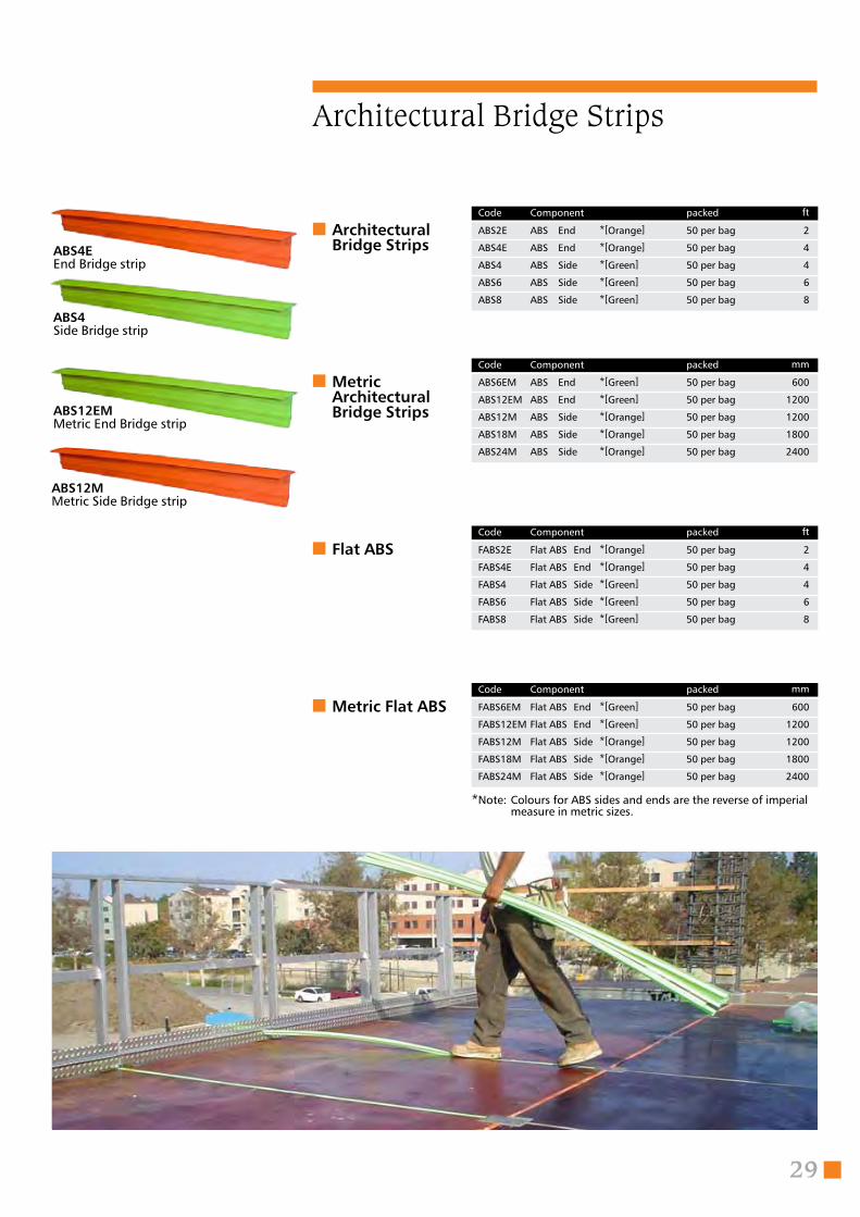
ABS2E ABS End *[Orange] 50 per bag 2
ABS4E ABS End *[Orange] 50 per bag 4
ABS4 ABS Side *[Green] 50 per bag 4
ABS6 ABS Side *[Green] 50 per bag 6
ABS8 ABS Side *[Green] 50 per bag 8
Code Component packed ft
Architectural Bridge Strips
Architectural Bridge Strips
ABS6EM ABS End *[Green] 50 per bag 600
ABS12EM ABS End *[Green] 50 per bag 1200
ABS12M ABS Side *[Orange] 50 per bag 1200
ABS18M ABS Side *[Orange] 50 per bag 1800
ABS24M ABS Side *[Orange] 50 per bag 2400
Code Component packed mm
Metric Architectural Bridge Strips
FABS2E Flat ABS End *[Orange] 50 per bag 2
FABS4E Flat ABS End *[Orange] 50 per bag 4
FABS4 Flat ABS Side *[Green] 50 per bag 4
FABS6 Flat ABS Side *[Green] 50 per bag 6
FABS8 Flat ABS Side *[Green] 50 per bag 8
Code Component packed ft
Flat ABS
FABS6EM Flat ABS End *[Green] 50 per bag 600
FABS12EM Flat ABS End *[Green] 50 per bag 1200
FABS12M Flat ABS Side *[Orange] 50 per bag 1200
FABS18M Flat ABS Side *[Orange] 50 per bag 1800
FABS24M Flat ABS Side *[Orange] 50 per bag 2400
Code Component packed mm
Metric Flat ABS
ABS4EEnd Bridge strip
ABS4Side Bridge strip
ABS12EMMetric End Bridge strip
ABS12MMetric Side Bridge strip
*Note: Colours for ABS sides and ends are the reverse of imperial measure in metric sizes.
30
Code of Safe Practices
Code of Safe Practices for erecting and dismantling vertical shoring
Reprinted with permission from page 168 of the Scaffold Industry Association Code of Safe Practices.If this notice is not readily available, cut and post on jobsite
It shall be the responsibility of all employers and users to read and comply with the following com-mon sense guidelines, which are designed to promote safety in the erection, dismantling and use of vertical shoring. These guidelines are not all inclusive nor do they supplant or replace other addi-tional safety and precautionary
measures to cover usual or unusual conditions. If these guidelines conflict in any way with any state, local, provincial or federal govern-ment statute or regulation, said statute or regulation shall super-sede these guidelines and it shall be the responsibility of each user to comply therewith and also to be knowledgeable.
These safety guidelines (Code of Safe Practice) set forth common sense procedures for safely erect-ing, dismantling and using shoring. However, equipment and shoring systems differ, and accordingly, ref-erence must always be made to the instructions and procedures of the supplier and or manufacturer of the equipment. Since field conditions vary and are beyond the control of the S.I.A., safe and proper use of shoring is the sole responsibility of the user.
guying or bracing when height exceeds 4 times the minimum base dimension and at lesser heights when stability is a concern.
K) Give special consideration totemporary loading. Areas where re-bar, material or equipment is to be stored temporarily may need to be strengthened to meet these loads.
L) Do not climb cross braces.M) Use special precautions when
shoring from or to sloped surfaces.N) Shoring loads are intended to be
carried by vertical legs. Loading of horizontal members may require special consideration. Consult your shoring supplier for allowable loads on horizontal members.
O) Avoid eccentric (off center) loads on U-Heads, top places and similar members by centering stringer loads on those members.
III. Guidelines for Dismantling Shoring
A) Do not remove braces or back off on adjustment screws or post shores until proper authority is given.
B) Dismantled equipment should be stockpiled in a planned manner and distributed to avoid concentrated loads on the partially cured concrete.
C) Use proper access equipment in the dismantling process.
IV. Guidelines for ReshoringA) Reshoring procedure should be
approved by a qualified engineer.
L) Erecting and dismantling of shoring requires good physical condition. Do not work on shoring if you feel dizzy, unsteady in any way or are impaired in any way by drugs or any other substance.
II. Guidelines for Erection and Use of Shoring
A) Provide and maintain a solid foot-ing. The sills or cribbing for shoring shall be sound, rigid and capable of carrying the maximum design load without setting or moving.
B) Always use baseplates. When sills or cribbing are used, base plates must be centered on them.
C) Adjusting screws shall be used to adjust to uneven grade conditions. Maintain all screw adjustments within the recommended height for the design load.
D) Plumb and level all shoring frames and single post shores as the erec-tion proceeds. DO NOT force braces on frames. Level the shoring towers until proper fit can be made. Maintain all shoring towers plumb and level.
E) Maintain the shore frame spacings and tower heights as shown on the shoring drawing. Where jobsite conditions require deviations from the shoring drawing, consult a qualified person.
F) Single post shores shall be stabi-lized in two directions. Bracing shall be installed as the shores are being erected.
G) Single Post Shores More Than One Tier High shall not be used. Where greater shore heights are required, consult the shoring supplier.
H) Adjustment of shoring to raise or lower formwork shall not be made during concrete placement.
I) If motorized concrete equipment is to be used, be sure that the shoring layout has been designed for use with this equipment and so noted on the layout, or drawing.
J) Use caution when erecting free-standing towers. Prevent tipping by
I. General Guidelines A) Post these shoring safety guide-
lines in a conspicuous place and be sure that all persons who erect, dismantle or use shoring are aware of them and also use them in Tool Box Safety Meetings.
B) Follow all state, local and federal codes, ordinances and regulations pertaining to shoring.
C) Survey the job site. A survey shall be made of the job site by a com-petent person for hazards, such as untamped earth fills, ditches, debris, high tension wires, unguarded open-ings, and other hazardous conditions created by other trades. These condi-tions should be corrected or avoided as noted in the following sections.
D) Plan shoring erection sequence in advance and obtain necessary access equipment to accomplish the work.
E) Inspect all equipment before using. Never use any equipment that is damaged or defective in any way. Mark it or tag it as defective. Then remove it from the jobsite.
F) A shoring drawing, consistent with the shoring manufacture’s recom-mended safe working loads, shall be prepared by a qualified person (or professional engineer where required), and used on the jobsite at all times.
G) Erect, dismantle or alter shoring only under the supervision of a qualified person.
H) Do not abuse or misuse the shoring equipment.
I) Inspect erected shoring: (a) imme-diately prior to concrete placement; (b) during concrete placement; (c) while vibrating concrete, and (d) after concrete placement until concrete is set.
J) Never take changes if in doubt regarding the safety or use of the shoring, consult your shoring supplier.
K) Use shoring equipment only for the purposed or in ways for which it was intended. Use proper tools when installing equipment.
Give a copy of this document to your workers and post it on the job site.
Additional notes from Tabla shoring.Always seek advice before starting erecting and carefully study provided shoring layout drawings and the Tabla Shoring System manual including safety notices. Users, always consult professional advise when in any doubt whatsoever or however small. This information does not purport to address the many job site conditions that can arise. Always stop work and ask for advice when in doubt. Compare for compatibility, all provided shoring drawings with jobsite conditions and structural & architectural drawings and specifications. Report immediately any discrepancies. Do not erect when in doubt.
These guidelines are provided by Tabla Shoring as common sense guide-line ONLY, to alert users and workers to (some of) the jobsite conditions to be avoided or professionally allowed for. This manual cannot suppose to address every possible jobsite condition which may arise – these conditions must be identified and addressed by site professional management and site safety.
Safety NoticeThis Publication contains instructions concerning the use of Tabla Shoring Systems.
Every effort has been made to provide safe, reliable equipment. It is important that Tabla equip-ment be erected and used prop-erly and safely and in conformity with government regulatory agencies, local regulations, Tabla recommendations and recogn-ised codes of practice which are applicable to the Tabla Modular Shoring System.
Consult Tabla Construction Systems to assure safe practice and to furnish additional items of equipment where necessary to maintain maximum standards of safety.
In order to assure proper fit, safety and compliance with government regulations & codes in the use of this equipment, do not mix this equipment with components of others.
Tabla Construction Systems Inc.1541 Hurontario St., Suite 200Mississauga, Ontario Canada L5G 3H7Phone: 905-844-5300Fax: 905-844-5303Web: www.tablashoring.comEmail: [email protected]
31
Tabla Safety
Safety RulesIt is unsafe as well as unlawful to use this equip-ment without proper supervision.
Be extra careful around cantilever and edge conditions. Watch out for wind conditions (wind is a powerful force).
Follow all drawings and instructions from the manufacturer and the professional engineer. If you have any doubts, stop and talk immediately with your supervisor.
Make sure that you follow all the informed instructions from your supervisor.
You could get seriously injured from improper erection or use of this equipment.
Erecting workers, make sure you are familiar with, and follow, safe practices, instructions and all safety rules contained herein.
Stop if you are uneasy in any way; consult your supervisor.
The Code of Safe Practices Safety Rules are on the opposite page. Write, email or visit our web site for extra copies are required at your job site.
More injuries occur each year as a result of operatives not wearing and using “Personal Protection equiPment”. Don’t take the risk, your safety at work is paramount to you, your family and your employer.
PPE
Illustrations and specifications contained in this and other Tabla Construction Systems publications are based on the latest product information. Tabla Constructions Systemsreserves the right to make changes at any time, without notice.
Illustrations are typical ideas and are not to be
Illustrations and specifications contained in this and other Tabla Construction Systems publications are based on the latest product information. Tabla Constructions Systemsreserves the right to make changes at any time, without notice.
Illustrations are typical ideas and are not to be
used for construction. They are not engineered and are for illustration purposes only.
Special Notes: Always use skilled erectors. Always consult Performance Safety Manual. If one is not available check www.tablashoring.com or call 905-844-5300.
used for construction. They are not engineered and are for illustration purposes only.
Special Notes: Always use skilled erectors. Always consult Performance Safety Manual. If one is not available check www.tablashoring.com or call 905-844-5300.
Tabla Construction Systems Inc.1541 Hurontario St., Suite 200Mississauga, Ontario, Canada L5G 3H7Phone: 905-844-5300 • Fax: 905-844-5303Web: tablashoring.com • Email: [email protected]
Tabla Construction Systems Inc.1541 Hurontario St., Suite 200Mississauga, Ontario, Canada L5G 3H7Phone: 905-844-5300 • Fax: 905-844-5303Web: tablashoring.com • Email: [email protected]