Embed Size (px)
Citation preview
9/2/2003 Broadcast Systems 1
Transmitters and Receivers
A Session for“Electronics and Telecommunications”
A Fairfield University E-CoursePowered by LearnLinc
9/2/2003 Broadcast Systems 2
Module: Communication Systems(in two parts)
• Texts:– “Understanding Telephone Electronics,” Bigelow,
Newnes, 1997, ISBN 0-7506-9944• References:
– Electronics Tutorial (Thanks to Alex Pounds)– Electronics Tutorial (Thanks to Mark Sokos)
• Part 11 – Broadcast Systems– 5 on-line sessions plus one lab
• Part 12 – Transmission & Communications– 5 on-line sessions plus one lab
• Mastery Test part 6 follows this Module
9/2/2003 Broadcast Systems 3
Section 11: Broadcast Systems
• Frequency Division Multiplexing• AM
– Modulation– Demodulation (The Envelope Detector)
• FM– Modulation– Demodulation (The Phase-Locked-Loop)
• Super Heterodyne Receivers• Television• Sampling
9/2/2003 Broadcast Systems 4
Section 12: Transmission and Networks
• Transmission Lines– Twisted pair– Coaxial Cable– Optical Fiber
• Microwave Systems• Satellite Links• Telephone Systems• Local Area Networks• Cellular Phone Systems
9/2/2003 Broadcast Systems 5
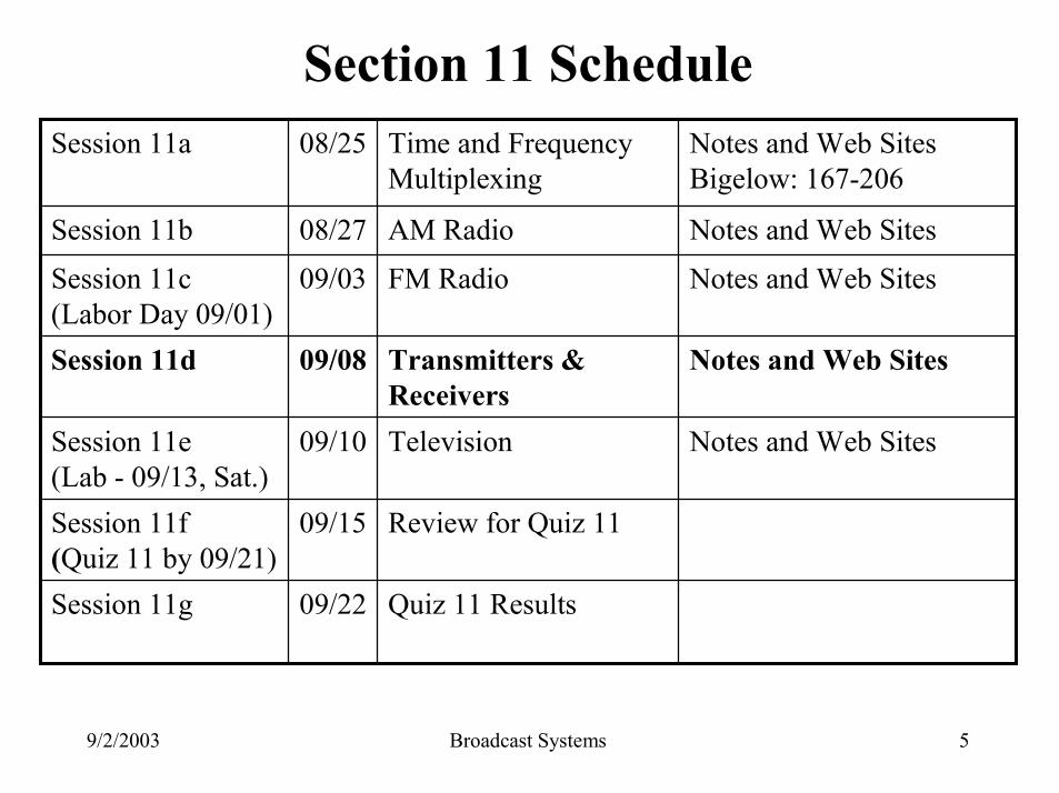
Section 11 Schedule
Quiz 11 Results09/22Session 11g
Review for Quiz 1109/15Session 11f(Quiz 11 by 09/21)
Notes and Web SitesTelevision09/10Session 11e (Lab - 09/13, Sat.)
Notes and Web SitesTransmitters & Receivers
09/08Session 11d
Notes and Web SitesFM Radio09/03Session 11c(Labor Day 09/01)
Notes and Web SitesAM Radio08/27Session 11b
Notes and Web SitesBigelow: 167-206
Time and Frequency Multiplexing
08/25Session 11a
9/2/2003 Broadcast Systems 6
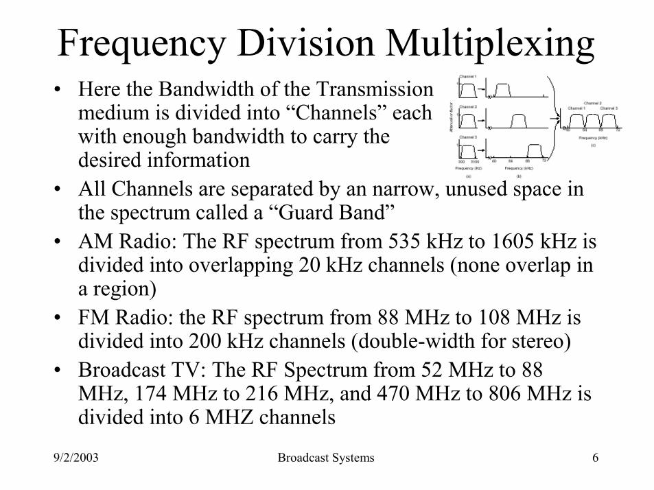
Frequency Division Multiplexing• Here the Bandwidth of the Transmission
medium is divided into “Channels” each with enough bandwidth to carry the desired information
• All Channels are separated by an narrow, unused space in the spectrum called a “Guard Band”
• AM Radio: The RF spectrum from 535 kHz to 1605 kHz is divided into overlapping 20 kHz channels (none overlap in a region)
• FM Radio: the RF spectrum from 88 MHz to 108 MHz is divided into 200 kHz channels (double-width for stereo)
• Broadcast TV: The RF Spectrum from 52 MHz to 88 MHz, 174 MHz to 216 MHz, and 470 MHz to 806 MHz is divided into 6 MHZ channels
9/2/2003 Broadcast Systems 7
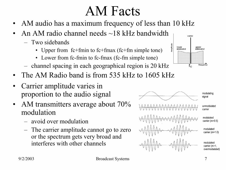
AM Facts• AM audio has a maximum frequency of less than 10 kHz• An AM radio channel needs ~18 kHz bandwidth
– Two sidebands • Upper from fc+fmin to fc+fmax (fc+fm simple tone)• Lower from fc-fmin to fc-fmax (fc-fm simple tone)
– channel spacing in each geographical region is 20 kHz or more• The AM Radio band is from 535 kHz to 1605 kHz• Carrier amplitude varies in
proportion to the audio signal • AM transmitters average about 70%
modulation– avoid over modulation– The carrier amplitude cannot go to zero
or the spectrum gets very broad and interferes with other channels
9/2/2003 Broadcast Systems 8
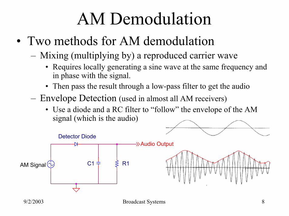
AM Demodulation• Two methods for AM demodulation
– Mixing (multiplying by) a reproduced carrier wave• Requires locally generating a sine wave at the same frequency and
in phase with the signal.• Then pass the result through a low-pass filter to get the audio
– Envelope Detection (used in almost all AM receivers)• Use a diode and a RC filter to “follow” the envelope of the AM
signal (which is the audio)
Audio OutputDetector Diode
R1C1AM Signal
9/2/2003 Broadcast Systems 9
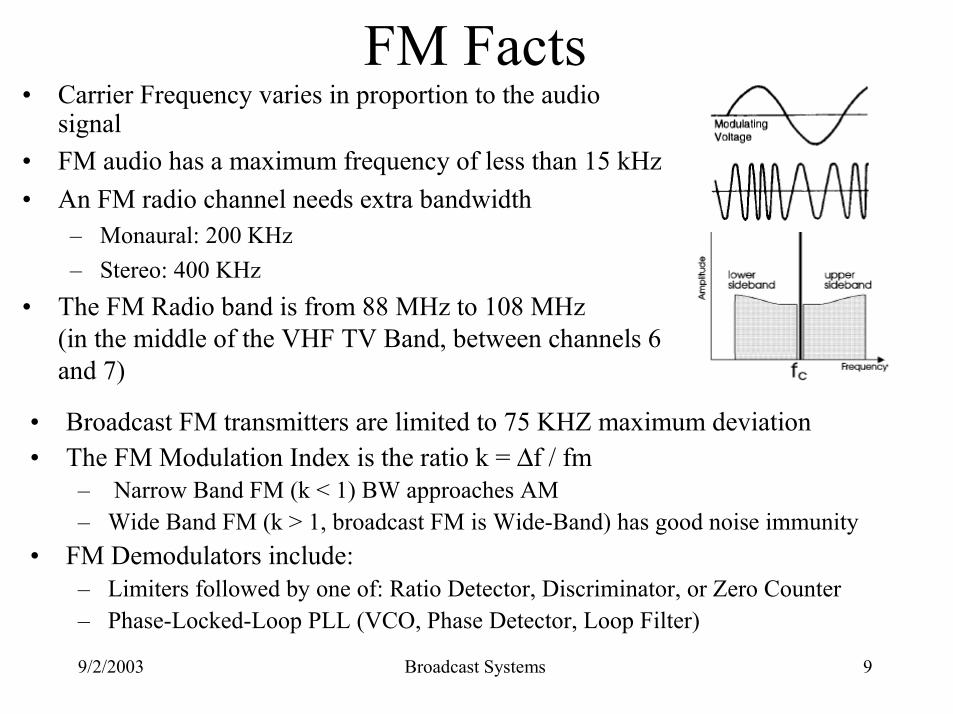
FM Facts• Carrier Frequency varies in proportion to the audio
signal • FM audio has a maximum frequency of less than 15 kHz• An FM radio channel needs extra bandwidth
– Monaural: 200 KHz – Stereo: 400 KHz
• The FM Radio band is from 88 MHz to 108 MHz(in the middle of the VHF TV Band, between channels 6 and 7)
• Broadcast FM transmitters are limited to 75 KHZ maximum deviation• The FM Modulation Index is the ratio k = ∆f / fm
– Narrow Band FM (k < 1) BW approaches AM– Wide Band FM (k > 1, broadcast FM is Wide-Band) has good noise immunity
• FM Demodulators include:– Limiters followed by one of: Ratio Detector, Discriminator, or Zero Counter– Phase-Locked-Loop PLL (VCO, Phase Detector, Loop Filter)
9/2/2003 Broadcast Systems 10
Demodulating FM• Limiter
– An FM signal has no Amplitude variation(any that is there is either from noise or interference)
– Amplify the signal and put it through a Limiter (Clipper – creates an almost square wave)to remove any AM
– Filter out the created harmonics (odd multiples of the carrier in the square wave) to get back a clean FM Modulated Sine Wave
• Detector– Use the slope of a filter to create AM that is proportional to the FM
and use an envelope detector (Ratio Detector, Discriminator)– Count zero crossings per second– Use a Phase-Locked-Loop (PLL) to track the time-varying carrier
9/2/2003 Broadcast Systems 11
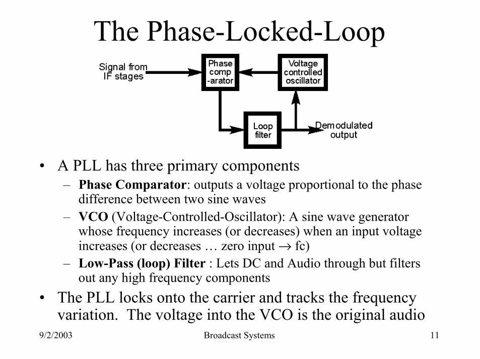
The Phase-Locked-Loop
• A PLL has three primary components– Phase Comparator: outputs a voltage proportional to the phase
difference between two sine waves– VCO (Voltage-Controlled-Oscillator): A sine wave generator
whose frequency increases (or decreases) when an input voltage increases (or decreases … zero input → fc)
– Low-Pass (loop) Filter : Lets DC and Audio through but filters out any high frequency components
• The PLL locks onto the carrier and tracks the frequency variation. The voltage into the VCO is the original audio
9/2/2003 Broadcast Systems 12
RF Transmitters
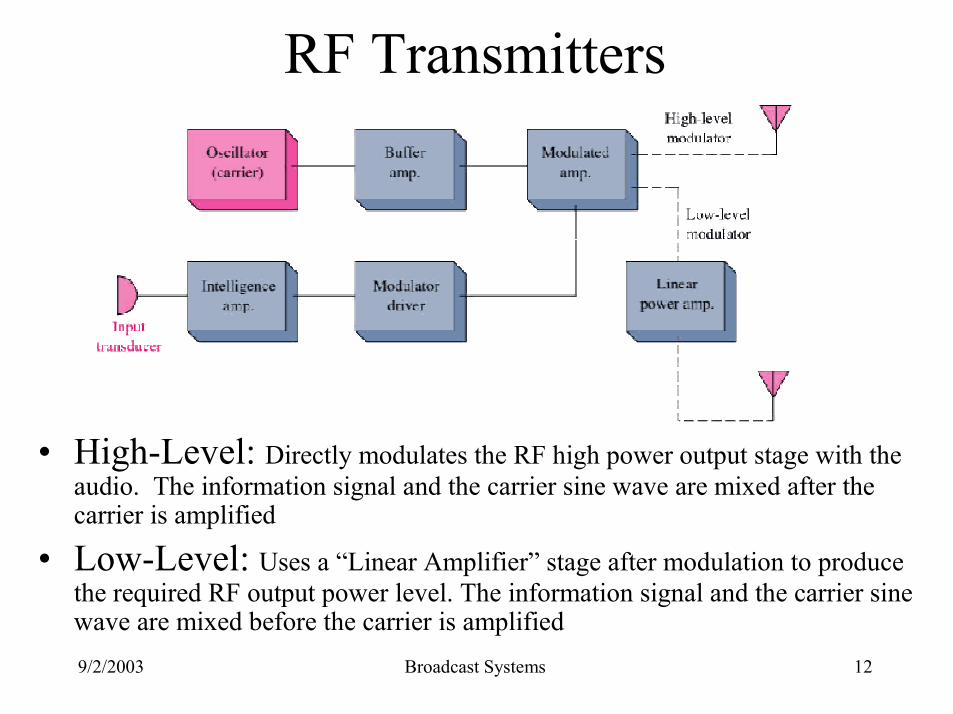
• High-Level: Directly modulates the RF high power output stage with the audio. The information signal and the carrier sine wave are mixed after the carrier is amplified
• Low-Level: Uses a “Linear Amplifier” stage after modulation to produce the required RF output power level. The information signal and the carrier sine wave are mixed before the carrier is amplified
9/2/2003 Broadcast Systems 13
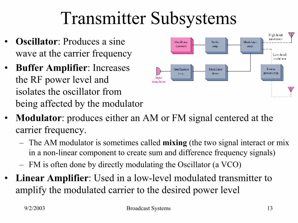
Transmitter Subsystems• Oscillator: Produces a sine
wave at the carrier frequency• Buffer Amplifier: Increases
the RF power level and isolates the oscillator from being affected by the modulator
• Modulator: produces either an AM or FM signal centered at the carrier frequency. – The AM modulator is sometimes called mixing (the two signal interact or mix
in a non-linear component to create sum and difference frequency signals)– FM is often done by directly modulating the Oscillator (a VCO)
• Linear Amplifier: Used in a low-level modulated transmitter to amplify the modulated carrier to the desired power level
9/2/2003 Broadcast Systems 14
AM Super Heterodyne Receiver
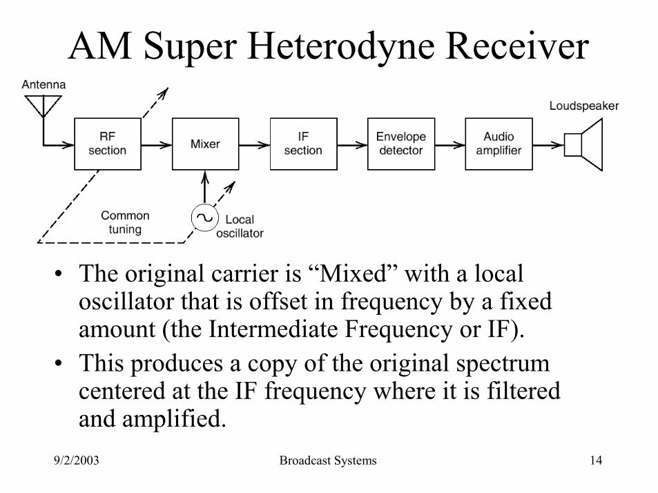
• The original carrier is “Mixed” with a local oscillator that is offset in frequency by a fixed amount (the Intermediate Frequency or IF).
• This produces a copy of the original spectrum centered at the IF frequency where it is filtered and amplified.
9/2/2003 Broadcast Systems 15
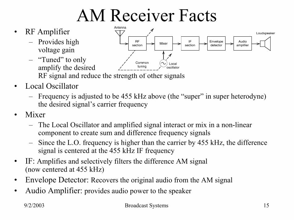
AM Receiver Facts• RF Amplifier
– Provides high voltage gain
– “Tuned” to only amplify the desired RF signal and reduce the strength of other signals
• Local Oscillator– Frequency is adjusted to be 455 kHz above (the “super” in super heterodyne)
the desired signal’s carrier frequency• Mixer
– The Local Oscillator and amplified signal interact or mix in a non-linear component to create sum and difference frequency signals
– Since the L.O. frequency is higher than the carrier by 455 kHz, the difference signal is centered at the 455 kHz IF frequency
• IF: Amplifies and selectively filters the difference AM signal (now centered at 455 kHz)
• Envelope Detector: Recovers the original audio from the AM signal• Audio Amplifier: provides audio power to the speaker
9/2/2003 Broadcast Systems 16
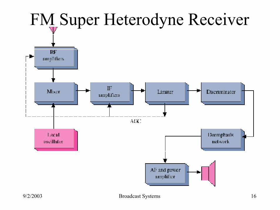
FM Super Heterodyne Receiver
9/2/2003 Broadcast Systems 17
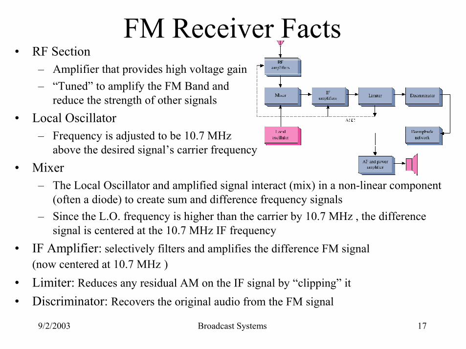
FM Receiver Facts• RF Section
– Amplifier that provides high voltage gain– “Tuned” to amplify the FM Band and
reduce the strength of other signals• Local Oscillator
– Frequency is adjusted to be 10.7 MHz above the desired signal’s carrier frequency
• Mixer– The Local Oscillator and amplified signal interact (mix) in a non-linear component
(often a diode) to create sum and difference frequency signals– Since the L.O. frequency is higher than the carrier by 10.7 MHz , the difference
signal is centered at the 10.7 MHz IF frequency• IF Amplifier: selectively filters and amplifies the difference FM signal
(now centered at 10.7 MHz )• Limiter: Reduces any residual AM on the IF signal by “clipping” it• Discriminator: Recovers the original audio from the FM signal
9/2/2003 Broadcast Systems 18
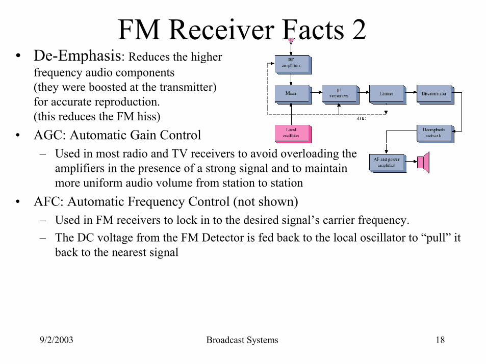
FM Receiver Facts 2• De-Emphasis: Reduces the higher
frequency audio components (they were boosted at the transmitter) for accurate reproduction.(this reduces the FM hiss)
• AGC: Automatic Gain Control– Used in most radio and TV receivers to avoid overloading the
amplifiers in the presence of a strong signal and to maintainmore uniform audio volume from station to station
• AFC: Automatic Frequency Control (not shown)– Used in FM receivers to lock in to the desired signal’s carrier frequency.– The DC voltage from the FM Detector is fed back to the local oscillator to “pull” it
back to the nearest signal
9/2/2003 Broadcast Systems 19
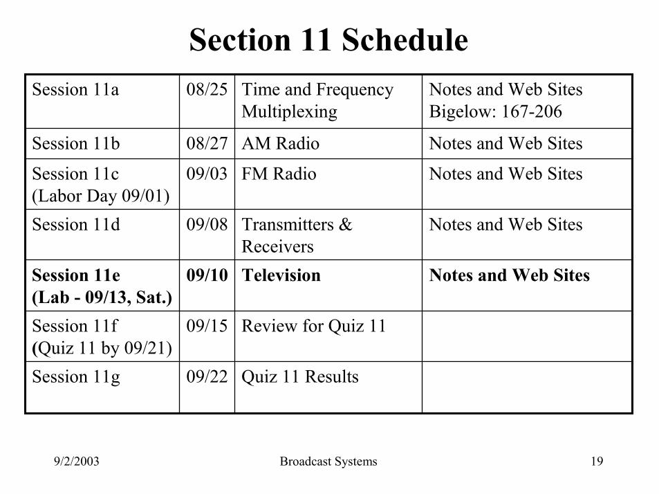
Section 11 Schedule
Quiz 11 Results09/22Session 11g
Review for Quiz 1109/15Session 11f(Quiz 11 by 09/21)
Notes and Web SitesTelevision09/10Session 11e (Lab - 09/13, Sat.)
Notes and Web SitesTransmitters & Receivers
09/08Session 11d
Notes and Web SitesFM Radio09/03Session 11c(Labor Day 09/01)
Notes and Web SitesAM Radio08/27Session 11b
Notes and Web SitesBigelow: 167-206
Time and Frequency Multiplexing
08/25Session 11a