Embed Size (px)
Citation preview
Dallas, Texas
TRAINING MANUAL
816R FM TRANSMITTERS
Dallas, Texas
TRAINING MANUAL
816R FM TRANSMITTERS
Instructor, David ChenowethContinental Electronics Technical Support Group
Phone (214) 388-5800FAX (214) 275-2314
E-Mail, [email protected] [email protected]
Continental Electronics Marketing at DallasPhone (214) 381-7161FAX (214) 381-3250
Internet Web Page, http://www.contelec.com
991027

FEATURES816R SERIES FM TRANSMITTERS
P Completely Self Contained (power levels through (30.0 KW)
P 4CX15000A Final Amplifier Tube (power levels thru 27.5 kW)
Easy to cool.Plate dissipation approximately 50% rated.Rebuilt tubes give excellent results.No frequency selected components - Same components cover all frequencies.1/4 Wave wide-band cavity.Screen grid at DC ground for stability.
P Wide-band Solid State IPA
Two independent 400 watt rated MOSFET AmplifiersEach amplifier is “hot plugable”Complete Protection.
Over CurrentOver Temperature.
700 Watt rating - Typically runs at 500-550 watts.High Gain - No Driver Required.
P 802B Wide-band Exciter, 802D-1 Digital Exciter Optional
No production or test selected components in the 802B.No Tuned circuits in the RF path following the Modulated Oscillator.50 Watt output will drive Power Amplifier to approximately 25% Power.Low Noise.
P SCR Primary Power Control
Controls Primary voltage for Plate and Screen Power Supplies. Maintains constant plate voltage/screenvoltage ratio for excellent Synchronous AM noise.
P Regulated Filament Voltage
P VSWR Protection
VSWR FoldbackAllows transmitter to operate at maximum safe power output under antenna icing conditions.Controls Plate and Screen voltage - not drive power or screen voltage only.
High Speed VSWR OverloadAutomatic Recycle.Easily adjusted.
P Easy Maintenance Access
P All Features Standard - No Options
Rev. April 10, 1999
1
816R FM TRANSMITTERTRAINING MANUAL
I. GENERAL INFORMATION
INTRODUCTION
The 816R transmitters operate in the FMbroadcast range with Power Output in the rangeof 2.5 kW to 35 kW. Reduced power is availableby tap changes of the plate and screentransformer to meet customer requirements.When the exciter receives input from the optionalstereo generator and SCA generator, thetransmitter provides continuous monaural,stereophonic, and SCA (subsidiarycommunication authorization)frequency-modulated programs. Reduced poweris available by tap changes of the plate andscreen transformer to meet customerrequirements.
816R-1C 2.5kW - 11kW816R-2C 10kW - 21.5kW816R-3C 10kW - 25kW816R-4C 10kW - 27.5kW816R-6C 10kW - 30kW816R-5C 15kW - 35kW
Table 1, Transmitter Rated Power
816R Series, (Except 816R-5C, 35kWTransmitter)
All the 816R series transmitters are completelyself contained, including the harmonic or lowpass filter, except the 816R-5C which has aseparate plate transformer and rectifier cabinet. The primary power is connected to the maintransmitter cabinet in all transmitters.
816R-5C, 35kw Transmitter
The 816R-5C plate transformer and rectifiercabinet has no controls, fans or blowers,interlocks, or circuit breakers and may be placedat any convenient location within 100 feet of themain transmitter cabinet. The ends of the platetransformer cabinet may be placed against other
equipment or wall and the back may be placed asclose as six inches from a wall or otherequipment. It is only necessary to have access tothe top and front side of the plate transformercabinet. It will be necessary have one 2 inch andone 1 inch conduit between the main transmittercabinet and the plate transformer cabinet.Primary power is connected to the maintransmitter cabinet.
816R-1C 1611 lbs816R-2C 1962 lbs816R-3C 2000 lbs816R-4C 2000 lbs816R-5CMain transmitter cabinet 1657 lbsPlate Transformer Cabinet 901 lbs816R-6C 2100 lbs
Table 2, Transmitter Weight (approx)
FUNCTIONAL DESCRIPTION
The transmitter consists of an exciter, asolid-state driver, and a power amplifier. Theoutput of the exciter is applied to the driver. Thedriver consists of two combined 400 wattmodules. The input to the driver is amplified toapproximately 500 watts and applied to thepower amplifier that contains one 4CX15000Ain power levels of 27.5mkW and lower. The 30and 35 kW transmitters use the YC130 tube. All are operated class C. The output of thepower amplifier is applied to a 50-ohmunbalanced load. Power control circuits monitorthe RF output power level. When a change inoutput power is detected, these circuits changethe plate voltage to compensate. Other controlcircuits within the transmitter monitor reflectedpower, forward power, operating voltage, airpressure and exhaust air temperature within thepower amplifier section. They protect the
2
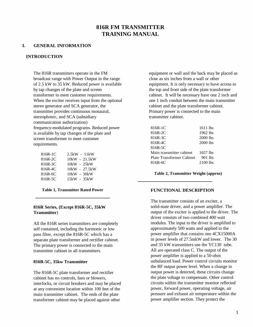
Figure 1, Tuning
transmitter by removing power when excessivecurrents, VSWR, loss of air pressure, orexcessive air exhaust temperature occur.
PHYSICAL DESCRIPTION
The transmitter is housed in a unistrut cabinetthat contains all transmitter components. Thetransmitter contains three sections. The sectionon the left contains the power amplifier. Thecenter section houses the control panel, exciter,driver circuits, and control circuits. The sectionon the right contains the power supplies, thecircuit breakers, and fuse panel. (The 35 kWtransmitter's High Voltage Power Supply isexternal and contains the High VoltageTransformer, Rectifiers, and TransientSuppression Circuits.)
II. OPERATION
GENERAL
The transmitter may be operated from the localcontrol panel or by remote control. Once thetransmitter has been installed and properlytuned, it is only necessary to monitor meterindications and to make periodic minor tuningand loading adjustments. Instructions for the802B exciter are found in the Exciter InstructionManual.
PA TUNING AND LOADING (For bestefficiency).
There is not likely to be a plate current dipwithin the normal range of tuning control. Thereare, however, three indicators to be observed forproper PA TUNE. Power output and screencurrent will be maximum. PA plate current willchange as the tuning is changed. Plate currentwill increase when the tuning control is held inthe raise position. When the shorting plane ispositioned correctly, the PA screen current andpower output will go through a peak. Refer toFigure 1 for an indication of what to expect asthe tuning control is run through its totalmechanical range, from one limit to the other.Notice that power output is the same at point Aand point B, but that plate current is greater atpoint B. The proper tuning point is at point Awhich results in maximum output and also the
least amount of platecurrent (not platecurrent dip). Theloading control isadjusted for maximumRF output. PA screencurrent decreases whenloading is raised andincreases when loadingis lowered. Normally,screen current isbetween 150 - 550mA. The screencurrent is dependentupon loading, poweroutput requirements,plate and screenvoltage, and individualtube characteristics.When the PA tube is
replaced, screen voltage may have to be changedin order to obtain the desired power output.
III. THEORY OF OPERATION
GENERAL
The FM Transmitter, 816R transmitters, operatein the 88 to 108 MHz range at maximum ratedRF outputs of 21.5 kW to 35 kW. A CEC 802Series solid state, wide-band, FM exciterprovides excitation. The transmitter is equippedwith circuits that maintain constant poweroutput and protect the transmitter from overloadconditions. A control panel provides completetransmitter metering and tuning controls.
FUNCTIONAL DESCRIPTION
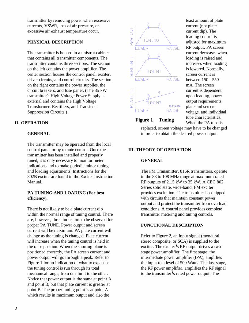
Refer to Figure 2, an input signal (monaural,stereo composite, or SCA) is supplied to theexciter. The exciter*s RF output drives a twostage power amplifier. The first stage, theintermediate power amplifier (IPA), amplifiesthe input to a level of 500 Watts. The last stage,the RF power amplifier, amplifies the RF signalto the transmitter*s rated power output. The
3
Figure 2, 816R Block Diagram
power amplifier is followed by a low pass filterand a directional coupler which is connected tothe station*s antenna system. A dc sample of theforward power from the directional coupler(DC1) is monitored by the auto power controlcircuit. If a change in output power is detected,a signal is sent to the power control board thatincreases or decreases the plate and screenpower supply input voltage to compensate. Asample of the reflected power is also monitoredby the power control circuits. If an excessiveamount of reflected power is detected, thecontrol circuits remove the transmitter platevoltage. The 28 V dc power supply providespower for the control circuits.
RF CIRCUITS
Refer to Figures 2 and 4 for a simplifieddiagram of the RF drive path. The drive pathconsists of the exciter A4, intermediate poweramplifier (IPA) A3AR1 with its directionalcoupler A3DC1, coupling capacitor A12C1,and power amplifier (PA) V1 with its gridtuning components A12C3, A12L1-L3, and
A12C2.
IPA Amplifier Module, A3AR1
The IPA is a modular assembly mounted in aroll-out drawer. It consists of two combinedsingle stage amplifier modules. The amplifiersare broadband solid state (MOSFET) design,rated at 400 Watts each with internal currentand thermal protection.. The protection circuitoperates on individual modules leaving thegood one on if there is a problem with one.
The IPA receives its dc power from a 45 V dcsupply on A5. The IPA is followed by adirectional coupler, A3DC1. The couplerdrives the IPA RF power meter. The RF outputof the directional coupler is connected to theRF power amplifier cavity.
IPA Metering, A3.
The IPA metering panel permits measurementof IPA supply voltage, current, forward RFpower, and reflected RF power. Additionally,
4
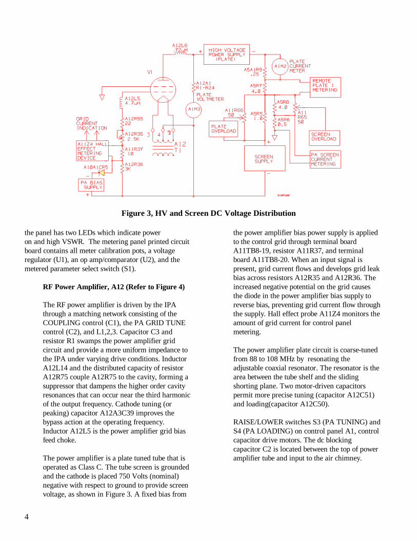
Figure 3, HV and Screen DC Voltage Distribution
the panel has two LEDs which indicate power on and high VSWR. The metering panel printed circuitboard contains all meter calibration pots, a voltageregulator (U1), an op amp/comparator (U2), and themetered parameter select switch (S1).
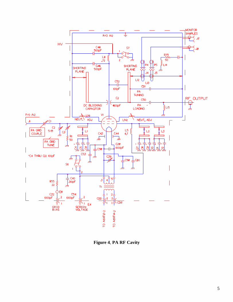
RF Power Amplifier, A12 (Refer to Figure 4)
The RF power amplifier is driven by the IPAthrough a matching network consisting of theCOUPLING control (C1), the PA GRID TUNEcontrol (C2), and L1,2,3. Capacitor C3 andresistor R1 swamps the power amplifier gridcircuit and provide a more uniform impedance tothe IPA under varying drive conditions. InductorA12L14 and the distributed capacity of resistorA12R75 couple A12R75 to the cavity, forming asuppressor that dampens the higher order cavityresonances that can occur near the third harmonicof the output frequency. Cathode tuning (orpeaking) capacitor A12A3C39 improves thebypass action at the operating frequency.Inductor A12L5 is the power amplifier grid biasfeed choke.
The power amplifier is a plate tuned tube that isoperated as Class C. The tube screen is groundedand the cathode is placed 750 Volts (nominal)negative with respect to ground to provide screenvoltage, as shown in Figure 3. A fixed bias from
the power amplifier bias power supply is appliedto the control grid through terminal boardA11TB8-19, resistor A11R37, and terminalboard A11TB8-20. When an input signal ispresent, grid current flows and develops grid leakbias across resistors A12R35 and A12R36. Theincreased negative potential on the grid causesthe diode in the power amplifier bias supply toreverse bias, preventing grid current flow throughthe supply. Hall effect probe A11Z4 monitors theamount of grid current for control panelmetering.
The power amplifier plate circuit is coarse-tunedfrom 88 to 108 MHz by resonating theadjustable coaxial resonator. The resonator is thearea between the tube shelf and the slidingshorting plane. Two motor-driven capacitorspermit more precise tuning (capacitor A12C51)and loading(capacitor A12C50).
RAISE/LOWER switches S3 (PA TUNING) andS4 (PA LOADING) on control panel A1, controlcapacitor drive motors. The dc blockingcapacitor C2 is located between the top of poweramplifier tube and input to the air chimney.
5
Figure 4, PA RF Cavity
6
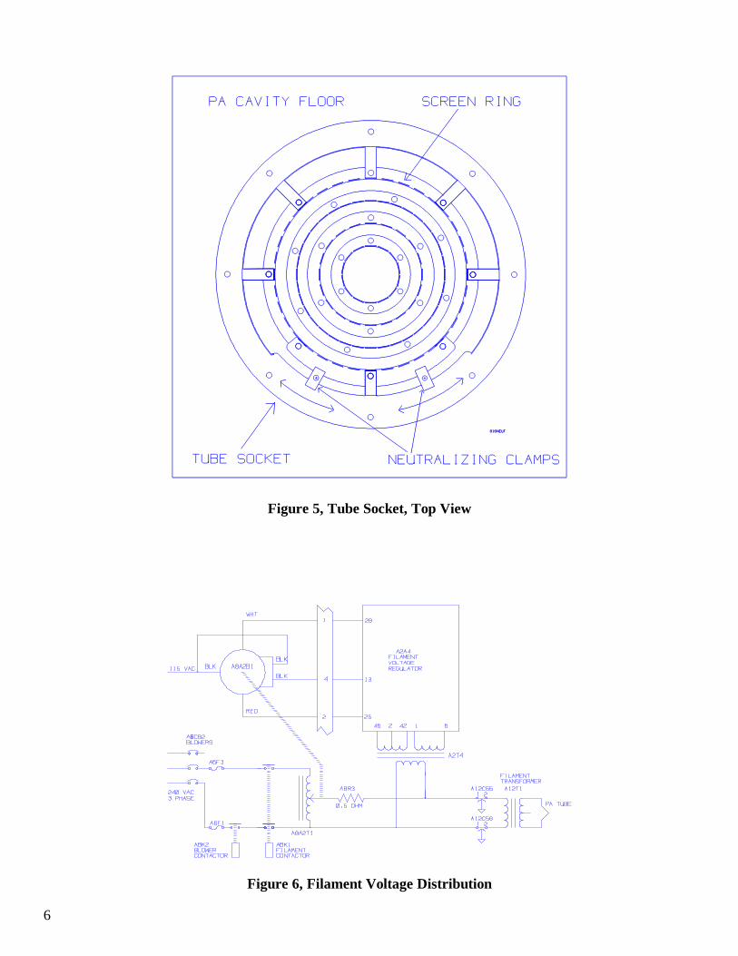
Figure 5, Tube Socket, Top View
Figure 6, Filament Voltage Distribution
7
Low-Pass Filter, A7.
Low Pass filter A7 consists of two coaxial filters intandem. The first filter has a cutoff frequency of130 MHz, while the second has a cutoff frequencyof 300 MHz.
Directional Coupler, DC1.
The directional coupler provides a proportional dcvoltage to both the forward and reflected circuits ofA2A6. The output of each is then routed to, andcan be displayed on, the Forward/ Reflected Meter(A1M4).
POWER SUPPLIES AND POWERCONTROL CIRCUITS
General.
There are five separate power supplies in thetransmitter. Three of the five, the plate, screen andpower amplifier bias power supplies providevoltages to the power amplifier. The IPA supply,furnishes voltage to the IPA stage. The 24 V dcpower supply provides power to the controlcircuits.
24 V dc Power Supply, P/O A10.
The 24 V dc supply is a fully self-containedregulated power supply mounted on the inside ofthe A10 Panel.
Power Amplifier Bias Power Supply, P/O A10.
The power amplifier bias power supply providesthe power amplifier with fixed grid bias that holdsthe tube near cutoff when no drive signal is presenton the grid. Single-phase primary power is appliedthrough contactor A8K1 and step-up transformerT1 to a bridge rectifier network. An L-section filteris formed by inductor L1 and capacitor C2. Thebias supply voltage is approximately 275 VDC,depending upon line voltage.
The power supply output is applied to the grid ofthe power amplifier through diode CR5. DiodeCR5 blocks grid current flow through the supplywhen the grid leak bias exceeds the fixed bias. Asample of the bias voltage is applied throughresistor R3 to front panel meter A1M1 for
monitoring.
Power Amplifier Plate Supply
The power amplifier plate power supply providespart of the plate voltage to the power amplifier.Primary components of the supply are transformerT1, 3-phase bridge rectifier assembly Z1, filterchoke L1, and filter capacitor C1. A metermultiplier board, A12A1, samples plate voltageand allows constant monitoring. Input power totransformer T1 is controlled by SCR(silicon-controlled rectifier) power control unit A9.This unit, connected as a closed loop regulator,maintains constant power output to offsetconditions of varying line voltage.
PA Screen Power Supply.
The 3-phase regulated voltage from the powercontrol unit is applied through transformer T2 to asilicon 3-phase full-wave bridge rectifier assemblyZ2 in the power amplifier screen power supply.The output of Z2 is filtered and applied to thecathode circuit of the power amplifier at thesecondary center tap of filament transformer T5.
IPA Power Supply, P/O A5.
The IPA power supply is a 3-phase full-wave typeusing a single section choke input filter. Itnominally delivers 45 V dc at 15-17 amperes to itsload. The supply*s primary power is switchedthrough relay A5K1 which is operated by thePLATE ON circuitry. The supply is protectedthrough circuit breaker A6CB3.
Power Control Unit, A9.
Power control unit A9 regulates the 3-phase acpower input to the power amplifier plate and thepower amplifier screen transformer. SCR assemblyA9Z1 has three SCR pairs; one pair in series witheach primary winding of the 3-phase powertransformers. Each pair is connected within thedelta circuit of the transformer primaries. Threecontrol cards are located within the A2 card cage.Each control card controls the firing (turn-on) pointof one SCR pair (Refer to Figure 7).
8
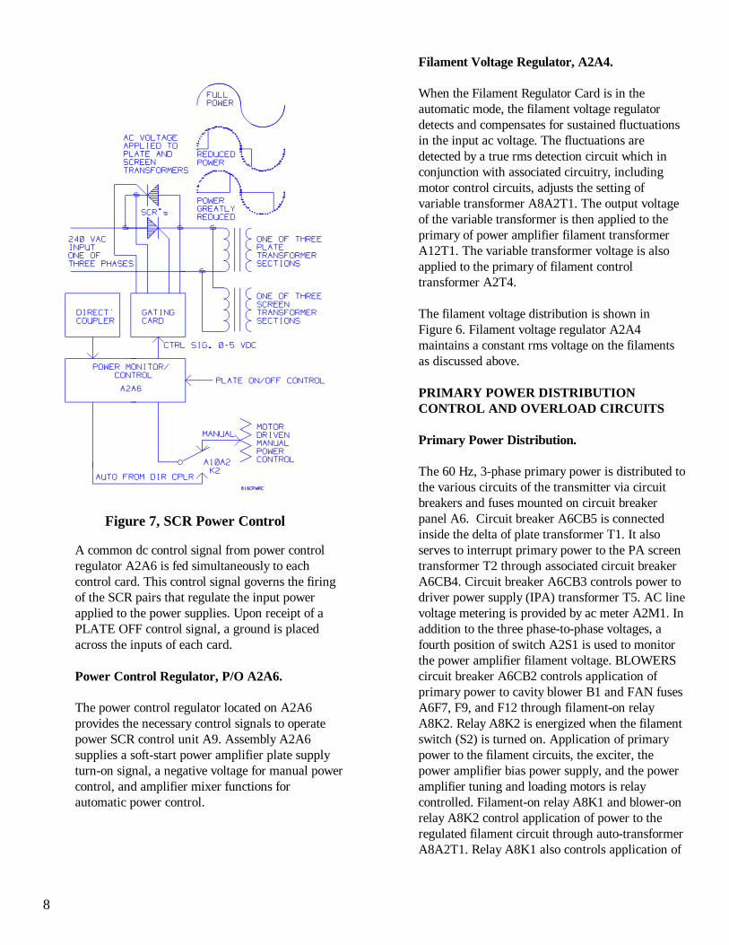
Figure 7, SCR Power Control
A common dc control signal from power controlregulator A2A6 is fed simultaneously to eachcontrol card. This control signal governs the firingof the SCR pairs that regulate the input powerapplied to the power supplies. Upon receipt of aPLATE OFF control signal, a ground is placedacross the inputs of each card.
Power Control Regulator, P/O A2A6.
The power control regulator located on A2A6provides the necessary control signals to operatepower SCR control unit A9. Assembly A2A6supplies a soft-start power amplifier plate supplyturn-on signal, a negative voltage for manual powercontrol, and amplifier mixer functions forautomatic power control.
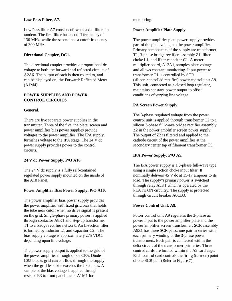
Filament Voltage Regulator, A2A4.
When the Filament Regulator Card is in theautomatic mode, the filament voltage regulatordetects and compensates for sustained fluctuationsin the input ac voltage. The fluctuations aredetected by a true rms detection circuit which inconjunction with associated circuitry, includingmotor control circuits, adjusts the setting ofvariable transformer A8A2T1. The output voltageof the variable transformer is then applied to theprimary of power amplifier filament transformerA12T1. The variable transformer voltage is alsoapplied to the primary of filament controltransformer A2T4.
The filament voltage distribution is shown inFigure 6. Filament voltage regulator A2A4maintains a constant rms voltage on the filamentsas discussed above.
PRIMARY POWER DISTRIBUTIONCONTROL AND OVERLOAD CIRCUITS
Primary Power Distribution.
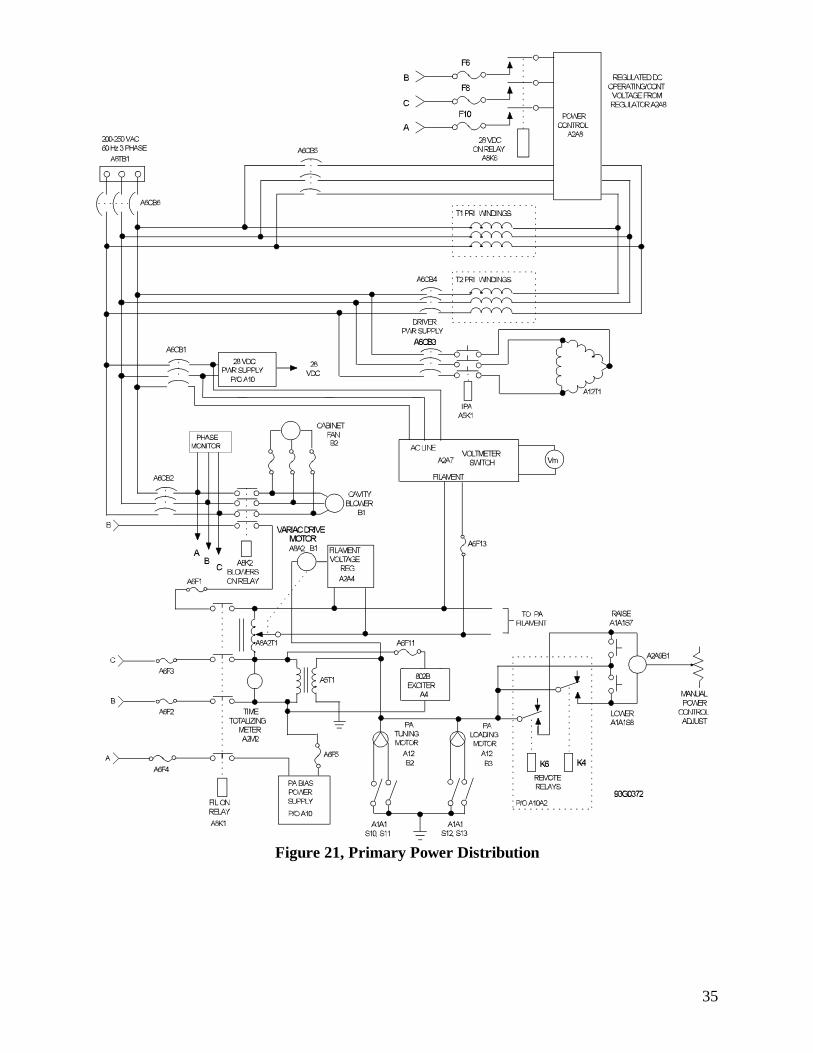
The 60 Hz, 3-phase primary power is distributed tothe various circuits of the transmitter via circuitbreakers and fuses mounted on circuit breakerpanel A6. Circuit breaker A6CB5 is connectedinside the delta of plate transformer T1. It alsoserves to interrupt primary power to the PA screentransformer T2 through associated circuit breakerA6CB4. Circuit breaker A6CB3 controls power todriver power supply (IPA) transformer T5. AC linevoltage metering is provided by ac meter A2M1. Inaddition to the three phase-to-phase voltages, afourth position of switch A2S1 is used to monitorthe power amplifier filament voltage. BLOWERScircuit breaker A6CB2 controls application ofprimary power to cavity blower B1 and FAN fusesA6F7, F9, and F12 through filament-on relayA8K2. Relay A8K2 is energized when the filamentswitch (S2) is turned on. Application of primarypower to the filament circuits, the exciter, thepower amplifier bias power supply, and the poweramplifier tuning and loading motors is relaycontrolled. Filament-on relay A8K1 and blower-onrelay A8K2 control application of power to theregulated filament circuit through auto-transformerA8A2T1. Relay A8K1 also controls application of
9
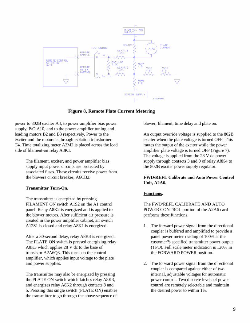
Figure 8, Remote Plate Current Metering
power to 802B exciter A4, to power amplifier bias powersupply, P/O A10, and to the power amplifier tuning andloading motors B2 and B3 respectively. Power to theexciter and the motors is through isolation transformerT4. Time totalizing meter A2M2 is placed across the loadside of filament-on relay A8K1.
The filament, exciter, and power amplifier biassupply input power circuits are protected byassociated fuses. These circuits receive power fromthe blowers circuit breaker, A6CB2.
Transmitter Turn-On.
The transmitter is energized by pressingFILAMENT ON switch A1S2 on the A1 controlpanel. Relay A8K2 is energized and is applied tothe blower motors. After sufficient air pressure iscreated in the power amplifier cabinet, air switchA12S1 is closed and relay A8K1 is energized.
After a 30-second delay, relay A8K4 is energized.The PLATE ON switch is pressed energizing relayA8K3 which applies 28 V dc to the base oftransistor A2A6Q3. This turns on the controlamplifier, which applies input voltage to the plateand power supplies.
The transmitter may also be energized by pressingthe PLATE ON switch which latches relay A8K3,and energizes relay A8K2 through contacts 8 and5. Pressing this single switch (PLATE ON) enablesthe transmitter to go through the above sequence of
blower, filament, time delay and plate on.
An output override voltage is supplied to the 802Bexciter when the plate voltage is turned OFF. Thismutes the output of the exciter while the poweramplifier plate voltage is turned OFF (Figure 7).The voltage is applied from the 28 V dc powersupply through contacts 3 and 9 of relay A8K4 tothe 802B exciter power supply regulator.
FWD/REFL Calibrate and Auto Power ControlUnit, A2A6.
Functions.
The FWD/REFL CALIBRATE AND AUTOPOWER CONTROL portion of the A2A6 cardperforms these functions.
1. The forward power signal from the directionalcoupler is buffered and amplified to provide apanel power meter reading of 100% at thecustomer*s specified transmitter power output(TPO). Full scale meter indication is 120% inthe FORWARD POWER position.
2. The forward power signal from the directionalcoupler is compared against either of twointernal, adjustable voltages for automaticpower control. Two discrete levels of powercontrol are remotely selectable and maintainthe desired power to within 1%.
10
3. The reflected power signal from the directionalcoupler is buffered and amplified to provide afull scale reading of 12% of the customer*sspecified TPO on the panel power meter in theREFLECTED POWER position.
4. The reflected power signal from the directionalcoupler is compared against an internal limit tosmoothly fold the forward power level backwhen a slowly rising VSWR level is detected.Forward power is reduced to keep the reflectedpower at 5 to 6% of the customer*s specifiedTPO.
5. A reflected power signal from the directionalcoupler can remove power from the transmitterand light the VSWR tally LED when a rapidlyrising reflected power level greater than 10% ofthe customer*s specified TPO is detected.
Overload Protection.
Relays A11K6, A11K7, and A11K9 are adjustedto energize and remove power from the transmitterwhen an overload occurs in the plate or screensupply or when the VSWR exceeds a preset level.Each relay is adjusted to trip at a factory presetcurrent level. The relay contacts are in series withplate control relay A8K3. If an overload occurs,the corresponding relay trips and de-energizes relayA8K3, removing plate power from the transmitter.
Overload and Recycle Board, A2A5.
Overload and recycle board A2A5 contains circuitsthat provide overload indication and memory,automatic power on recycling, and filament controlcircuit interlock status.
When an overload occurs in the PA plate, PAscreen, or VSWR circuits, a 28 V dc pulse issupplied to the appropriate SCR Q4, Q7, or Q8.The SCR latches and lights its associated LEDindicator on the A1 panel to indicate whichoverload has occurred. All indicators that havebeen lighted by an overload function remain lighteduntil FAULT RESET switch A1S11 on the maincontrol panel is pressed. Plate voltage is removedby overload relays A11K6, A11K7, or A11K9.The 28 V dc pulse that triggers the SCR issimultaneously routed to the recycle circuit via
diodes CR9, CR11, or CR12 to be used toautomatically restart the transmitter.
The automatic recycle circuit provides a timedrestart pulse for up to four overload occurrenceswithin a 30-second period. The card as shipped willallow only two restart pulses in a 30-second period.However, it may be reconfigured to allow fourrestart pulses in a 30-second period by removingthe jumper between terminals A and B on the cardand replacing it between A and C.
Power Failure Recycle Board, A8A1.
In the event of momentary loss of primary power,the power failure recycle circuit restores thetransmitter to operational status.
Power Control Relays, P/O A10A2.
Assembly A10A2 provides remote manual powerlower and raise control. When power is decreasedat the remote control panel, relay K4 is energized.Closed contacts provide 115 V ac to motorA2A9B1 which adjusts the resistance of A2A9R1to decrease the transmitter power output. When thepower is increased at the remote control panel,relay K6 is energized and closed contacts provide115 V ac to motor A2A9B1 which adjusts theresistance of A2A9R1 to increase the transmitterpower output.
Remote Relays, P/O A10A2.
Remote relays in A10A2 parallel the front panelcontrol operations. Failsafe relay K8 is energizedonly when 28 V dc is present in the control circuit.If the 28 V dc is lost, the relay de-energizes andremoves plate power from the transmitter. Secondpower level (low power) relay K7 must also beenergized continuously (28 V dc) to maintain thesecond power level.
11
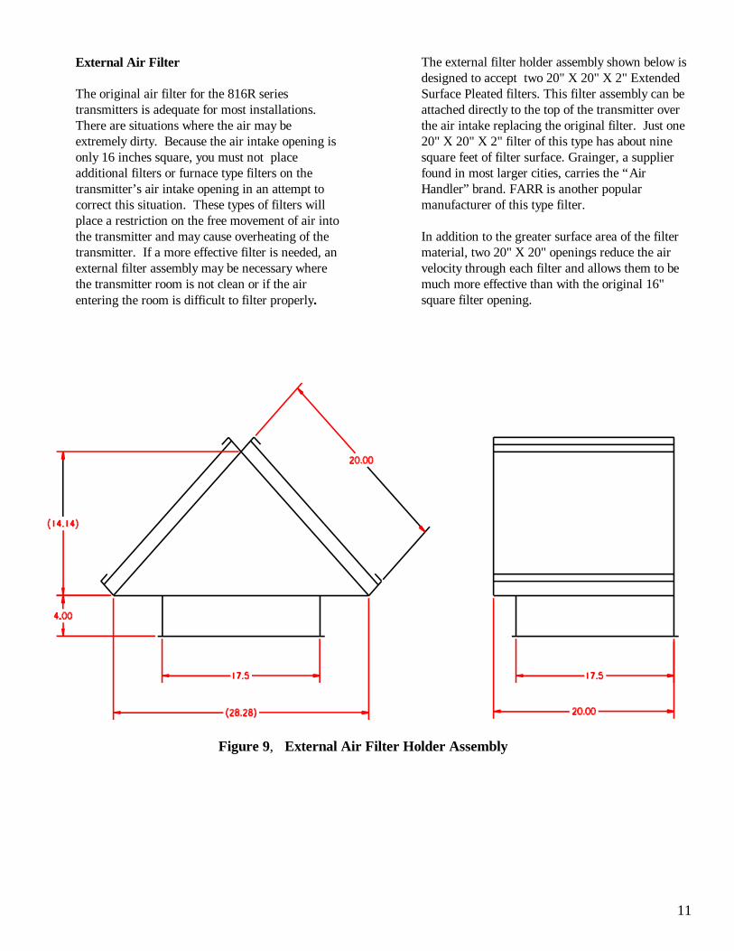
Figure 9, External Air Filter Holder Assembly
External Air Filter
The original air filter for the 816R seriestransmitters is adequate for most installations. There are situations where the air may beextremely dirty. Because the air intake opening isonly 16 inches square, you must not placeadditional filters or furnace type filters on thetransmitter’s air intake opening in an attempt tocorrect this situation. These types of filters willplace a restriction on the free movement of air intothe transmitter and may cause overheating of thetransmitter. If a more effective filter is needed, anexternal filter assembly may be necessary wherethe transmitter room is not clean or if the airentering the room is difficult to filter properly.
The external filter holder assembly shown below isdesigned to accept two 20" X 20" X 2" ExtendedSurface Pleated filters. This filter assembly can beattached directly to the top of the transmitter overthe air intake replacing the original filter. Just one20" X 20" X 2" filter of this type has about ninesquare feet of filter surface. Grainger, a supplierfound in most larger cities, carries the “AirHandler” brand. FARR is another popularmanufacturer of this type filter.
In addition to the greater surface area of the filtermaterial, two 20" X 20" openings reduce the airvelocity through each filter and allows them to be much more effective than with the original 16"square filter opening.
12
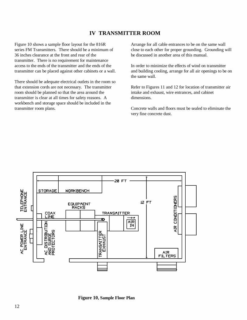
Figure 10, Sample Floor Plan
IV TRANSMITTER ROOM
Figure 10 shows a sample floor layout for the 816Rseries FM Transmitters. There should be a minimum of36 inches clearance at the front and rear of thetransmitter. There is no requirement for maintenanceaccess to the ends of the transmitter and the ends of thetransmitter can be placed against other cabinets or a wall.
There should be adequate electrical outlets in the room sothat extension cords are not necessary. The transmitterroom should be planned so that the area around thetransmitter is clear at all times for safety reasons. Aworkbench and storage space should be included in thetransmitter room plans.
Arrange for all cable entrances to be on the same wallclose to each other for proper grounding. Grounding willbe discussed in another area of this manual.
In order to minimize the effects of wind on transmitterand building cooling, arrange for all air openings to be onthe same wall.
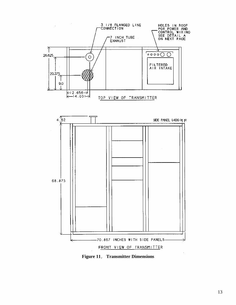
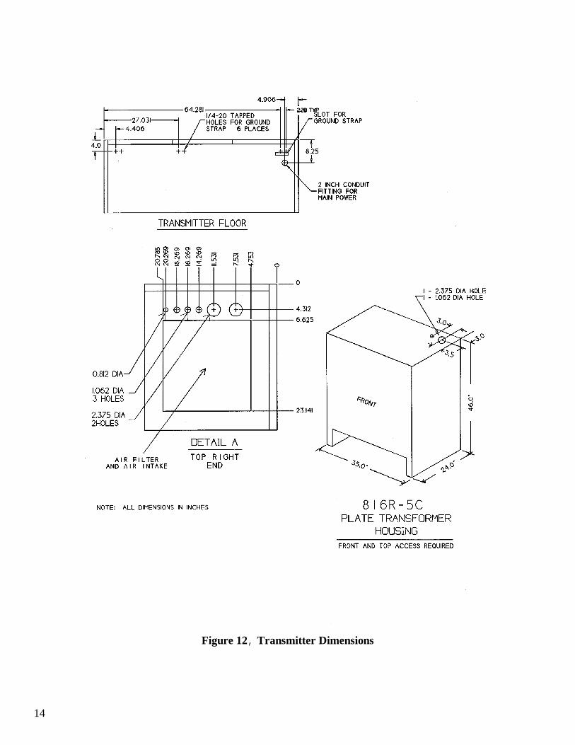
Refer to Figures 11 and 12 for location of transmitter airintake and exhaust, wire entrances, and cabinetdimensions.
Concrete walls and floors must be sealed to eliminate thevery fine concrete dust.
13
Figure 11, Transmitter Dimensions
14
Figure 12, Transmitter Dimensions
15
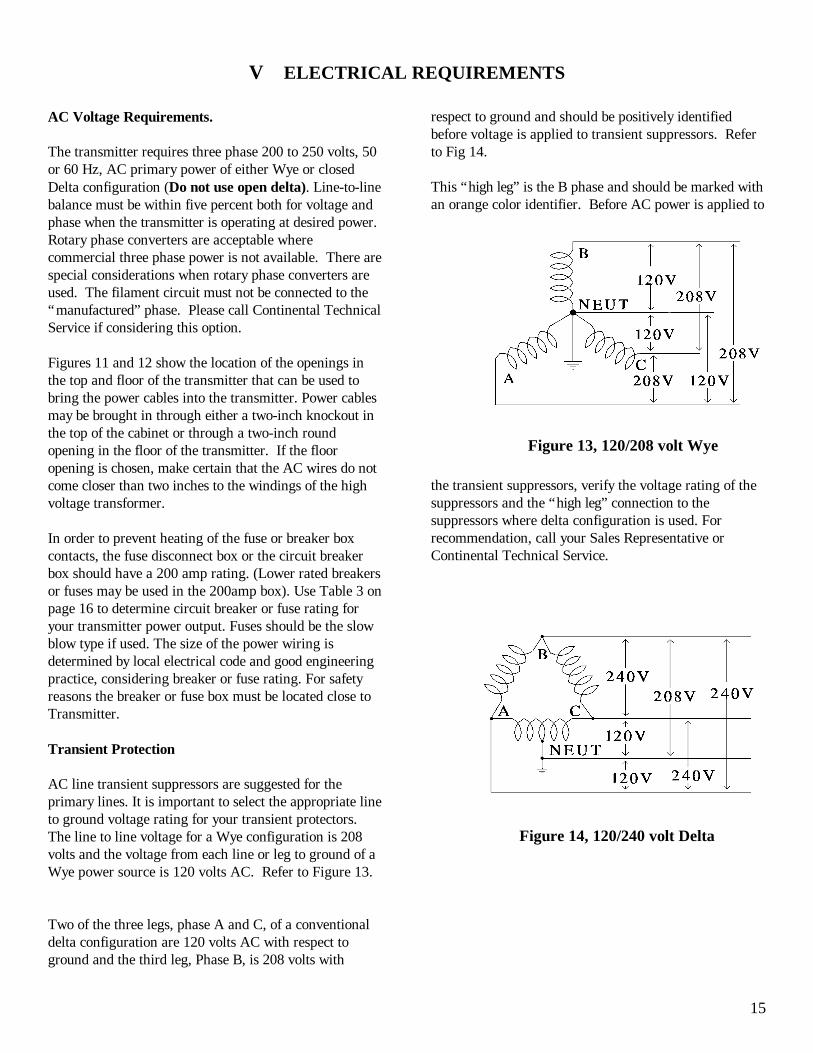
Figure 13, 120/208 volt Wye
Figure 14, 120/240 volt Delta
V ELECTRICAL REQUIREMENTS
AC Voltage Requirements.
The transmitter requires three phase 200 to 250 volts, 50or 60 Hz, AC primary power of either Wye or closedDelta configuration (Do not use open delta). Line-to-linebalance must be within five percent both for voltage andphase when the transmitter is operating at desired power. Rotary phase converters are acceptable wherecommercial three phase power is not available. There arespecial considerations when rotary phase converters areused. The filament circuit must not be connected to the“manufactured” phase. Please call Continental TechnicalService if considering this option.
Figures 11 and 12 show the location of the openings inthe top and floor of the transmitter that can be used tobring the power cables into the transmitter. Power cablesmay be brought in through either a two-inch knockout inthe top of the cabinet or through a two-inch roundopening in the floor of the transmitter. If the flooropening is chosen, make certain that the AC wires do notcome closer than two inches to the windings of the highvoltage transformer.
In order to prevent heating of the fuse or breaker boxcontacts, the fuse disconnect box or the circuit breakerbox should have a 200 amp rating. (Lower rated breakersor fuses may be used in the 200amp box). Use Table 3 onpage 16 to determine circuit breaker or fuse rating foryour transmitter power output. Fuses should be the slowblow type if used. The size of the power wiring isdetermined by local electrical code and good engineeringpractice, considering breaker or fuse rating. For safetyreasons the breaker or fuse box must be located close toTransmitter.
Transient Protection
AC line transient suppressors are suggested for theprimary lines. It is important to select the appropriate lineto ground voltage rating for your transient protectors. The line to line voltage for a Wye configuration is 208volts and the voltage from each line or leg to ground of aWye power source is 120 volts AC. Refer to Figure 13.
Two of the three legs, phase A and C, of a conventionaldelta configuration are 120 volts AC with respect toground and the third leg, Phase B, is 208 volts with
respect to ground and should be positively identifiedbefore voltage is applied to transient suppressors. Referto Fig 14.
This “high leg” is the B phase and should be marked withan orange color identifier. Before AC power is applied to
the transient suppressors, verify the voltage rating of thesuppressors and the “high leg” connection to thesuppressors where delta configuration is used. Forrecommendation, call your Sales Representative orContinental Technical Service.
16
Figure 15, Ground Rod Imperfect Ground
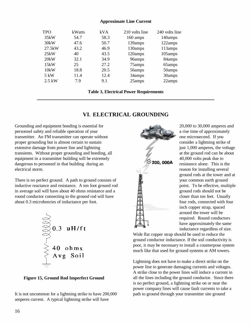
Approximate Line Current
TPO kWatts kVA 210 volts line 240 volts line35kW 54.7 58.3 160 amps 140amps30kW 47.6 50.7 139amps 122amps27.5kW 43.2 46.9 130amps 113amps25kW 40 43.5 120amps 105amps20kW 32.1 34.9 96amps 84amps15kW 25 27.2 75amps 65amps10kW 18.8 20.5 56amps 50amps5 kW 11.4 12.4 34amps 30amps2.5 kW 7.9 9.1 25amps 22amps
Table 3, Electrical Power Requirements
VI. ELECTRICAL GROUNDING
Grounding and equipment bonding is essential forpersonnel safety and reliable operation of yourtransmitter. An FM transmitter can operate withoutproper grounding but is almost certain to sustainextensive damage from power line and lightningtransients. Without proper grounding and bonding, allequipment in a transmitter building will be extremelydangerous to personnel in that building during anelectrical storm.
There is no perfect ground. A path to ground consists ofinductive reactance and resistance. A ten foot ground rodin average soil will have about 40 ohms resistance and a round conductor connecting to the ground rod will haveabout 0.3 microhenries of inductance per foot.
It is not uncommon for a lightning strike to have 200,000amperes current. A typical lightning strike will have
20,000 to 30,000 amperes anda rise time of approximatelyone microsecond. If youconsider a lightning strike ofjust 1,000 amperes, the voltageat the ground rod can be about40,000 volts peak due toresistance alone. This is thereason for installing severalground rods at the tower and atyour common earth groundpoint. To be effective, multipleground rods should not becloser than ten feet. Usuallyfour rods, connected with fourinch copper strap, spacedaround the tower will berequired. Round conductorshave approximately the sameinductance regardless of size.
Wide flat copper strap should be used to reduce theground conductor inductance. If the soil conductivity ispoor, it may be necessary to install a counterpose systemmuch like that used for ground systems at AM towers.
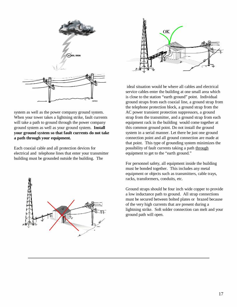
Lightning does not have to make a direct strike on thepower line to generate damaging currents and voltages. A strike close to the power lines will induce a current inall the lines including the ground conductor. Since thereis no perfect ground, a lightning strike on or near thepower company lines will cause fault currents to take apath to ground through your transmitter site ground
17
system as well as the power company ground system. When your tower takes a lightning strike, fault currentswill take a path to ground through the power companyground system as well as your ground system. Installyour ground system so that fault currents do not takea path through your equipment.
Each coaxial cable and all protection devices forelectrical and telephone lines that enter your transmitterbuilding must be grounded outside the building. The
ideal situation would be where all cables and electricalservice cables enter the building at one small area whichis close to the station “earth ground” point. Individualground straps from each coaxial line, a ground strap fromthe telephone protection block, a ground strap from theAC power transient protection suppressors, a groundstrap from the transmitter, and a ground strap from eachequipment rack in the building would come together atthis common ground point. Do not install the ground system in a serial manner. Let there be just one groundconnection point and all ground connection are made atthat point. This type of grounding system minimizes thepossibility of fault currents taking a path throughequipment to get to the “earth ground.”
For personnel safety, all equipment inside the buildingmust be bonded together. This includes any metalequipment or objects such as transmitters, cable trays,racks, transformers, conduits, etc.
Ground straps should be four inch wide copper to providea low inductance path to ground. All strap connectionsmust be secured between bolted plates or brazed becauseof the very high currents that are present during alightning strike. Soft solder connection can melt and yourground path will open.
18
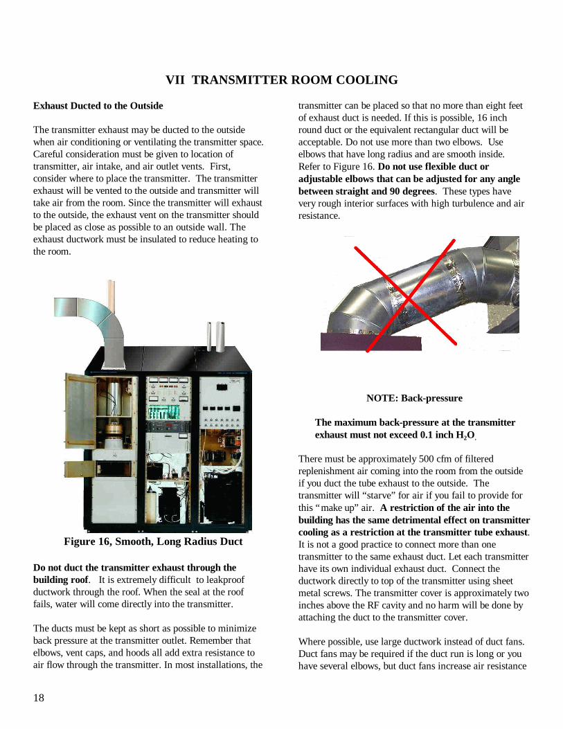
Figure 16, Smooth, Long Radius Duct
VII TRANSMITTER ROOM COOLING
Exhaust Ducted to the Outside
The transmitter exhaust may be ducted to the outsidewhen air conditioning or ventilating the transmitter space.Careful consideration must be given to location oftransmitter, air intake, and air outlet vents. First,consider where to place the transmitter. The transmitterexhaust will be vented to the outside and transmitter willtake air from the room. Since the transmitter will exhaustto the outside, the exhaust vent on the transmitter shouldbe placed as close as possible to an outside wall. Theexhaust ductwork must be insulated to reduce heating tothe room.
Do not duct the transmitter exhaust through thebuilding roof. It is extremely difficult to leakproofductwork through the roof. When the seal at the rooffails, water will come directly into the transmitter.
The ducts must be kept as short as possible to minimizeback pressure at the transmitter outlet. Remember thatelbows, vent caps, and hoods all add extra resistance toair flow through the transmitter. In most installations, the
transmitter can be placed so that no more than eight feetof exhaust duct is needed. If this is possible, 16 inchround duct or the equivalent rectangular duct will beacceptable. Do not use more than two elbows. Useelbows that have long radius and are smooth inside. Refer to Figure 16. Do not use flexible duct oradjustable elbows that can be adjusted for any anglebetween straight and 90 degrees. These types havevery rough interior surfaces with high turbulence and airresistance.
NOTE: Back-pressure
The maximum back-pressure at the transmitterexhaust must not exceed 0.1 inch H2O.
There must be approximately 500 cfm of filteredreplenishment air coming into the room from the outsideif you duct the tube exhaust to the outside. Thetransmitter will “starve” for air if you fail to provide forthis “make up” air. A restriction of the air into thebuilding has the same detrimental effect on transmittercooling as a restriction at the transmitter tube exhaust. It is not a good practice to connect more than onetransmitter to the same exhaust duct. Let each transmitterhave its own individual exhaust duct. Connect theductwork directly to top of the transmitter using sheetmetal screws. The transmitter cover is approximately twoinches above the RF cavity and no harm will be done byattaching the duct to the transmitter cover.
Where possible, use large ductwork instead of duct fans.Duct fans may be required if the duct run is long or youhave several elbows, but duct fans increase air resistance
19
if they fail; therefore, some method of monitoring air flowand interlocking the transmitter must be used if there isno alternative to the use of duct fans. It is a good practice to place the transmitter exhaust andthe building air intake on the same building wall. Thisarrangement allows pressure from the wind to be appliedequally to both inlet and exhaust, thus neutralizing theeffects of wind on the air system. The exhaust air will behot, and if returned to the room, will place an additionalload on the air cooling system. Make sure that there is nopossibility that the exhaust air can be returned to thebuilding air intake. This is usually accomplished byplacing the air intake high on the wall and directing theexhaust air downward and away from the intake opening. Always place the intake opening as high as possible toprovide the cleanest air to the air intake.
COOLING BY AIR CONDITIONING
Air conditioning a transmitter space results in a cleanenvironment for the transmitter and in some geographicalareas, is essential because of high ambient temperatures,high humidity or very dirty conditions. You may duct thetube exhaust to the outside or re-circulate the tubeexhaust back into the room. There is seldom a validreason to duct the transmitter air intake to the outside. The transmitter cabinet fan is designed to move a largevolume of air but not against air resistance. Where intakeducting is used, the intake duct must be very large inorder to prevent air starvation. If the outside air is hotenough to require air conditioning, the transmitter shouldhave the advantage of the cooler, cleaner air from theroom.
Air Conditioning units are mechanical and may fail. It isideal to have two identical units that are set to slightly (5degrees) different temperature settings. Because airconditioners operate most efficiently when runningcontinuously, select units that are marginal in theircapacity when operating alone. Arrange a selector switchto swap the thermostats from one air conditioner to theother. This will allow both units to accumulate equalrunning time without changing the thermostat settings.
The following paragraphs will help you determine theheat load that the transmitter generates but does notinclude other equipment or the building heat load from theoutside environment. Your HVAC contractor should beable to calculate the building cooling requirements.
CAUTION:
When you are totally dependant upon airconditioning equipment for cooling, the transmitterwill overheat if the air conditioning equipment fails. Temperature monitoring, temperature interlocks, andremote alarms are essential where air conditioning isused.
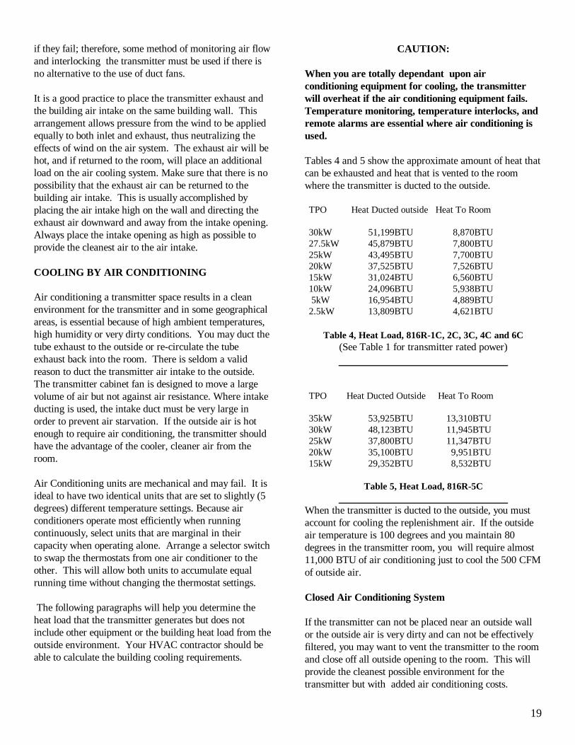
Tables 4 and 5 show the approximate amount of heat thatcan be exhausted and heat that is vented to the roomwhere the transmitter is ducted to the outside.
TPO Heat Ducted outside Heat To Room
30kW 51,199BTU 8,870BTU27.5kW 45,879BTU 7,800BTU25kW 43,495BTU 7,700BTU20kW 37,525BTU 7,526BTU15kW 31,024BTU 6,560BTU10kW 24,096BTU 5,938BTU 5kW 16,954BTU 4,889BTU2.5kW 13,809BTU 4,621BTU
Table 4, Heat Load, 816R-1C, 2C, 3C, 4C and 6C(See Table 1 for transmitter rated power)
TPO Heat Ducted Outside Heat To Room
35kW 53,925BTU 13,310BTU30kW 48,123BTU 11,945BTU25kW 37,800BTU 11,347BTU20kW 35,100BTU 9,951BTU15kW 29,352BTU 8,532BTU
Table 5, Heat Load, 816R-5C
When the transmitter is ducted to the outside, you mustaccount for cooling the replenishment air. If the outsideair temperature is 100 degrees and you maintain 80degrees in the transmitter room, you will require almost11,000 BTU of air conditioning just to cool the 500 CFMof outside air.
Closed Air Conditioning System
If the transmitter can not be placed near an outside wallor the outside air is very dirty and can not be effectivelyfiltered, you may want to vent the transmitter to the roomand close off all outside opening to the room. This willprovide the cleanest possible environment for thetransmitter but with added air conditioning costs.
20
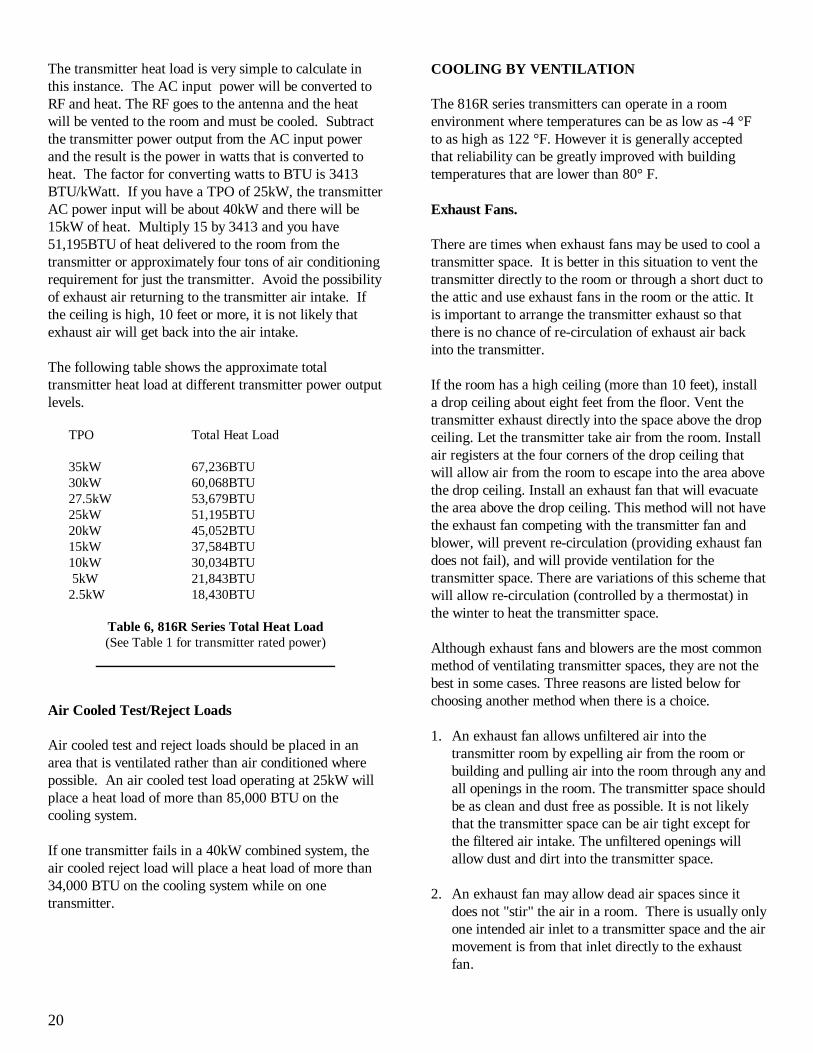
The transmitter heat load is very simple to calculate inthis instance. The AC input power will be converted toRF and heat. The RF goes to the antenna and the heatwill be vented to the room and must be cooled. Subtractthe transmitter power output from the AC input powerand the result is the power in watts that is converted toheat. The factor for converting watts to BTU is 3413BTU/kWatt. If you have a TPO of 25kW, the transmitterAC power input will be about 40kW and there will be15kW of heat. Multiply 15 by 3413 and you have51,195BTU of heat delivered to the room from thetransmitter or approximately four tons of air conditioningrequirement for just the transmitter. Avoid the possibilityof exhaust air returning to the transmitter air intake. Ifthe ceiling is high, 10 feet or more, it is not likely that exhaust air will get back into the air intake.
The following table shows the approximate totaltransmitter heat load at different transmitter power outputlevels.
TPO Total Heat Load
35kW 67,236BTU30kW 60,068BTU27.5kW 53,679BTU25kW 51,195BTU20kW 45,052BTU15kW 37,584BTU10kW 30,034BTU 5kW 21,843BTU2.5kW 18,430BTU
Table 6, 816R Series Total Heat Load(See Table 1 for transmitter rated power)
Air Cooled Test/Reject Loads
Air cooled test and reject loads should be placed in anarea that is ventilated rather than air conditioned wherepossible. An air cooled test load operating at 25kW willplace a heat load of more than 85,000 BTU on thecooling system.
If one transmitter fails in a 40kW combined system, theair cooled reject load will place a heat load of more than34,000 BTU on the cooling system while on onetransmitter.
COOLING BY VENTILATION
The 816R series transmitters can operate in a roomenvironment where temperatures can be as low as -4 °Fto as high as 122 °F. However it is generally acceptedthat reliability can be greatly improved with buildingtemperatures that are lower than 80° F.
Exhaust Fans. There are times when exhaust fans may be used to cool atransmitter space. It is better in this situation to vent thetransmitter directly to the room or through a short duct tothe attic and use exhaust fans in the room or the attic. Itis important to arrange the transmitter exhaust so thatthere is no chance of re-circulation of exhaust air backinto the transmitter.
If the room has a high ceiling (more than 10 feet), installa drop ceiling about eight feet from the floor. Vent thetransmitter exhaust directly into the space above the dropceiling. Let the transmitter take air from the room. Installair registers at the four corners of the drop ceiling thatwill allow air from the room to escape into the area abovethe drop ceiling. Install an exhaust fan that will evacuatethe area above the drop ceiling. This method will not havethe exhaust fan competing with the transmitter fan andblower, will prevent re-circulation (providing exhaust fandoes not fail), and will provide ventilation for thetransmitter space. There are variations of this scheme thatwill allow re-circulation (controlled by a thermostat) inthe winter to heat the transmitter space.
Although exhaust fans and blowers are the most commonmethod of ventilating transmitter spaces, they are not thebest in some cases. Three reasons are listed below forchoosing another method when there is a choice.
1. An exhaust fan allows unfiltered air into thetransmitter room by expelling air from the room orbuilding and pulling air into the room through any andall openings in the room. The transmitter space shouldbe as clean and dust free as possible. It is not likelythat the transmitter space can be air tight except forthe filtered air intake. The unfiltered openings willallow dust and dirt into the transmitter space.
2. An exhaust fan may allow dead air spaces since itdoes not "stir" the air in a room. There is usually onlyone intended air inlet to a transmitter space and the airmovement is from that inlet directly to the exhaustfan.
21
3. In installations where the transmitter is ducted to theoutside and takes air from the room, the exhaust fan iscompeting with the transmitter cabinet fan and cavityblower for air through the same room air inlet. In thissituation, the greater capacity of the exhaust fan willreduce the transmitter cooling if the room air inlet isnot large in size. Where exhaust fans or blowers areused, the room air intake must be large enough so thatthe room in not under negative pressure. Negativepressure at the transmitter air inlet has the samedetrimental effect as back pressure of the sameamount at the transmitter air exhaust.
Positive Pressure.
Positive pressure ventilation forces air into the room andthe air escapes through openings in the room and throughthe transmitter exhaust if ducted to the outside. The airmay be forced into the room with propeller type fans orwith centrifugal blowers. Propeller type fans move moreair with smaller motors than will centrifugal blowers. A30 or 36 inch fan is quiet and can move more than 3000cfm of air into a room and use only a 1/4HP motor. Someof the advantages of positive pressure ventilation are:
1. All the air entering the room comes through oneopening which can be easily filtered. When doors orwindows are opened, air moves out through theseopening.
2. A fan blowing air into a room will "stir" the room air,reducing the risk of dead air space. Deflectors at thefan can be used to direct air into areas that might nototherwise have moving air.
3. All fans aid each other. The fan that is forcing air intoa room is aiding the transmitter fans in cooling thetransmitter. All the fans, the room fan, the transmittercabinet fan, and the power amplifier cavity blower aremoving air in the same direction through thetransmitter.
4. Like the exhaust system, the pressure system will alsoventilate the room. The transmitter will exhaust about500 cu-ft/min. of air to the outside. If the room fan iscapable of moving three or four thousand cu-ft/min.of air into the room, another opening in the room mustbe provided for room ventilation.
An example of positive room ventilation will be describedhere. This is intended as an example and can be modifiedto meet your particular requirements.
Position the left end or the rear of the transmitter near anoutside wall in order to keep the exhaust ductwork asshort as possible. Position the transmitter so that theexhaust duct will not interfere with the coaxial RF outputline. If the total duct run is eight feet or less and there areno more than two elbows, 16 inch round or the equivalentrectangular duct can be connected directly over thetransmitter exhaust output using sheet metal screws. (Usecare when drilling holes for sheet metal screws so as toavoid metal shavings falling into the transmitter.) Theduct will have to be turned down at the outside to preventrain and snow from getting into it. A bell type transitionshould be used at the end of the duct to reduceturbulence.
The duct at the transmitter exhaust will have a damperthat will direct the exhaust to the outside or re-circulatethe exhaust air back into the room.. The damper will bemotor controlled so that the opening to the room will beclosed off at the same time that the air from thetransmitter will be directed to the outside. With thedamper in the second position, the air from thetransmitter will be directed to the room instead of outside.This arrangement will allow the transmitter to exhaust tothe outside in the summer and re-circulate to the inside inthe winter.
A fan that has enough capacity to change the room air atleast once each minute is installed in the wall. This fanpulls filtered air into the room through motor controlledlouvers. A 3000 cfm fan will change the air once aminute in a 15X20 foot room having a 10 foot ceiling.
An opening with motor controlled louvers is provided inthe same wall where the fan is mounted. The reason forintake fan and room air outlet being on the same wall isto minimize the effects of wind on the ventilation system.If both inlet and outlet are on the same wall, the effects ofwind, regardless of direction, is neutralized since the windpressure is the same on both. The transmitter air exhaustshould be on this wall also. The transmitter exhaustshould be positioned so that there is no risk of re-circulation.
With motor control on inlet and outlet louvers andtransmitter duct damper, it is possible to control theoperation of louvers, dampers, and the ventilation fanwith thermostats. Set the thermostats to maintain therequired equipment operating temperature at all times.Three conditions are described below:1. At temperatures above 85 °F, a condition of
maximum ventilation and cooling will result. Thetransmitter will be ducted to the outside and the intake
22
fan will be running. The outlet wall louvers will alsobe opened to permit room ventilation.
2. For temperatures between 65 °F and 85 °F, acondition of minimum ventilation will exist at timeswhen it is not necessary to run the room intake fan,but the transmitter should be vented to the outside.Under these conditions the transmitter exhaustdampers will direct the transmitter exhaust to theoutside, the outlet wall louvers will be closed, the fanwill be off, and the inlet fan louvers will be open toallow fresh filtered air into the room and transmitter.
3. For temperatures below 65 °F, a condition of re-circulation for heating will exist. The transmitterexhaust damper will be positioned to allowtransmitter exhaust air into the room and all outsideoutlets and inlets will be closed.
The system described will require two heating typethermostats and control relays. One will be set toapproximately 65 °F and the second will be set toapproximately 85 °F.
The thermostats should be mounted approximately sixfeet off the floor and in an area of the room where thetemperature is not influenced by heat radiated by thetransmitter or by direct air flow from the room intake fan.
The transmitter space should also be provided with athermostatically controlled heater that can be set toapproximately 50 °F. This will provide heat duringmaintenance periods or during times that the transmitteris off-the-air, if not a 24 hour operation.
23
TECHNICAL CHARACTERISTICS
MECHANICAL
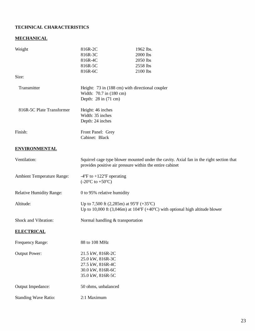
Weight 816R-2C 1962 lbs.816R-3C 2000 lbs816R-4C 2050 lbs816R-5C 2558 lbs816R-6C 2100 lbs
Size:
Transmitter Height: 73 in (188 cm) with directional couplerWidth: 70.7 in (180 cm)Depth: 28 in (71 cm)
816R-5C Plate Transformer Height: 46 inchesWidth: 35 inchesDepth: 24 inches
Finish: Front Panel: GreyCabinet: Black
ENVIRONMENTAL
Ventilation: Squirrel cage type blower mounted under the cavity. Axial fan in the right section thatprovides positive air pressure within the entire cabinet
Ambient Temperature Range: -4oF to +122oF operating(-20oC to +50oC)
Relative Humidity Range: 0 to 95% relative humidity
Altitude: Up to 7,500 ft (2,285m) at 95oF (+35oC)Up to 10,000 ft (3,046m) at 104oF (+40oC) with optional high altitude blower
Shock and Vibration: Normal handling & transportation
ELECTRICAL
Frequency Range: 88 to 108 MHz
Output Power: 21.5 kW, 816R-2C25.0 kW, 816R-3C27.5 kW, 816R-4C30.0 kW, 816R-6C35.0 kW, 816R-5C
Output Impedance: 50 ohms, unbalanced
Standing Wave Ratio: 2:1 Maximum
24
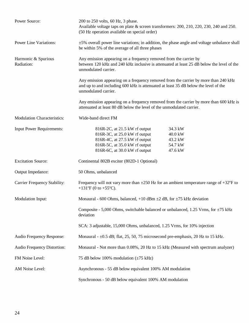
Power Source: 200 to 250 volts, 60 Hz, 3 phase.Available voltage taps on plate & screen transformers: 200, 210, 220, 230, 240 and 250.(50 Hz operation available on special order)
Power Line Variations: ±5% overall power line variations; in addition, the phase angle and voltage unbalance shallbe within 5% of the average of all three phases
Harmonic & Spurious Any emission appearing on a frequency removed from the carrier byRadiation: between 120 kHz and 240 kHz inclusive is attenuated at least 25 dB below the level of the
unmodulated carrier.
Any emission appearing on a frequency removed from the carrier by more than 240 kHzand up to and including 600 kHz is attenuated at least 35 dB below the level of theunmodulated carrier.
Any emission appearing on a frequency removed from the carrier by more than 600 kHz isattenuated at least 80 dB below the level of the unmodulated carrier.
Modulation Characteristics: Wide-band direct FM
Input Power Requirements: 816R-2C, at 21.5 kW rf output 34.3 kW 816R-3C, at 25.0 kW rf output 40.0 kW816R-4C, at 27.5 kW rf output 43.2 kW816R-5C, at 35.0 kW rf output 54.7 kW816R-6C, at 30.0 kW rf output 47.6 kW
Excitation Source: Continental 802B exciter (802D-1 Optional)
Output Impedance: 50 Ohms, unbalanced
Carrier Frequency Stability: Frequency will not vary more than ±250 Hz for an ambient temperature range of +32oF to+131oF (0 to +55oC).
Modulation Input: Monaural - 600 Ohms, balanced, +10 dBm ±2 dB, for ±75 kHz deviation
Composite - 5,000 Ohms, switchable balanced or unbalanced, 1.25 Vrms, for ±75 kHzdeviation
SCA: 3 adjustable, 15,000 Ohms, unbalanced, 1.25 Vrms, for 10% injection
Audio Frequency Response: Monaural - ±0.5 dB; flat, 25, 50, 75 microsecond pre-emphasis, 20 Hz to 15 kHz.
Audio Frequency Distortion: Monaural - Not more than 0.08%, 20 Hz to 15 kHz (Measured with spectrum analyzer)
FM Noise Level: 75 dB below 100% modulation (±75 kHz)
AM Noise Level: Asynchronous - 55 dB below equivalent 100% AM modulation
Synchronous - 50 dB below equivalent 100% AM modulation
25
816R TRANSMITTERINFORMATION SHEETS
Eimac Product Bulletin . . . . . . . . . . . . . . . . . . . . . . . . 26Three Phase Transmitter Primary Power Source . . . . . . 27Power Amplifier Grid Adjustment Procedure . . . . . . . . 28Power Controller Checkout Procedure . . . . . . . . . . . . . 30
26
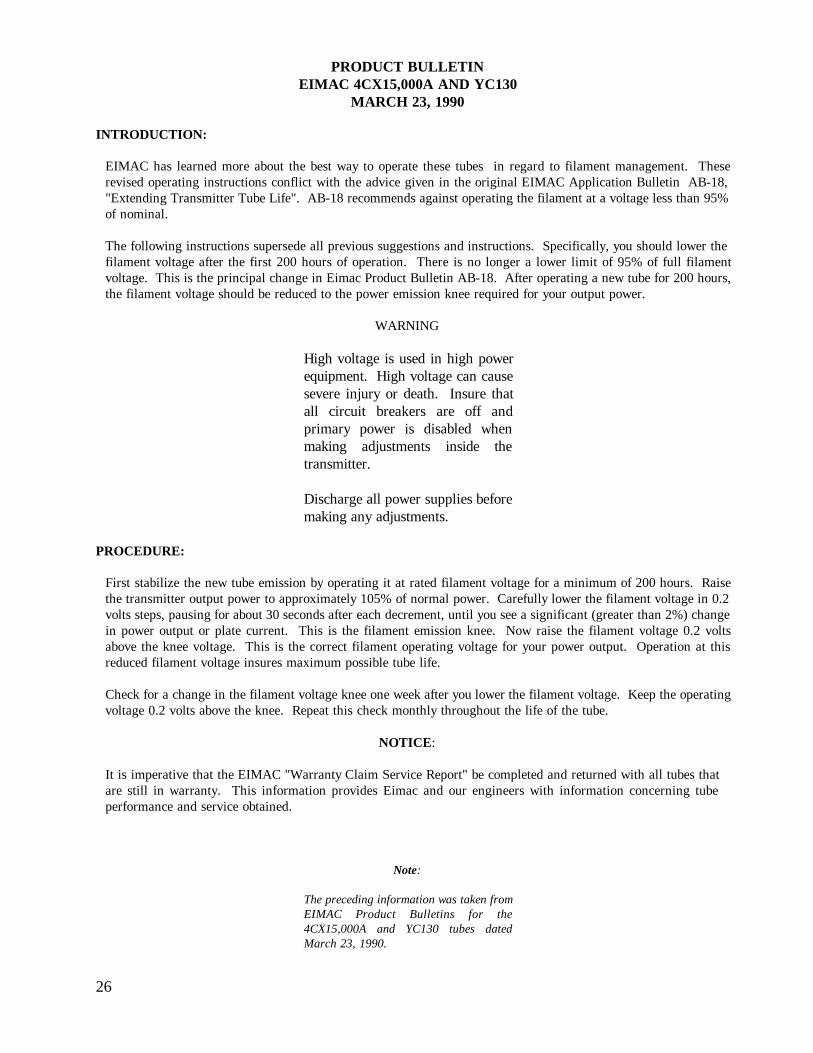
PRODUCT BULLETINEIMAC 4CX15,000A AND YC130
MARCH 23, 1990
INTRODUCTION:
EIMAC has learned more about the best way to operate these tubes in regard to filament management. Theserevised operating instructions conflict with the advice given in the original EIMAC Application Bulletin AB-18,"Extending Transmitter Tube Life". AB-18 recommends against operating the filament at a voltage less than 95%of nominal.
The following instructions supersede all previous suggestions and instructions. Specifically, you should lower thefilament voltage after the first 200 hours of operation. There is no longer a lower limit of 95% of full filamentvoltage. This is the principal change in Eimac Product Bulletin AB-18. After operating a new tube for 200 hours,the filament voltage should be reduced to the power emission knee required for your output power.
WARNING
High voltage is used in high powerequipment. High voltage can causesevere injury or death. Insure thatall circuit breakers are off andprimary power is disabled whenmaking adjustments inside thetransmitter.
Discharge all power supplies beforemaking any adjustments.
PROCEDURE:
First stabilize the new tube emission by operating it at rated filament voltage for a minimum of 200 hours. Raisethe transmitter output power to approximately 105% of normal power. Carefully lower the filament voltage in 0.2volts steps, pausing for about 30 seconds after each decrement, until you see a significant (greater than 2%) changein power output or plate current. This is the filament emission knee. Now raise the filament voltage 0.2 voltsabove the knee voltage. This is the correct filament operating voltage for your power output. Operation at thisreduced filament voltage insures maximum possible tube life.
Check for a change in the filament voltage knee one week after you lower the filament voltage. Keep the operatingvoltage 0.2 volts above the knee. Repeat this check monthly throughout the life of the tube.
NOTICE:
It is imperative that the EIMAC "Warranty Claim Service Report" be completed and returned with all tubes thatare still in warranty. This information provides Eimac and our engineers with information concerning tubeperformance and service obtained.
Note:
The preceding information was taken fromEIMAC Product Bulletins for the4CX15,000A and YC130 tubes datedMarch 23, 1990.
27
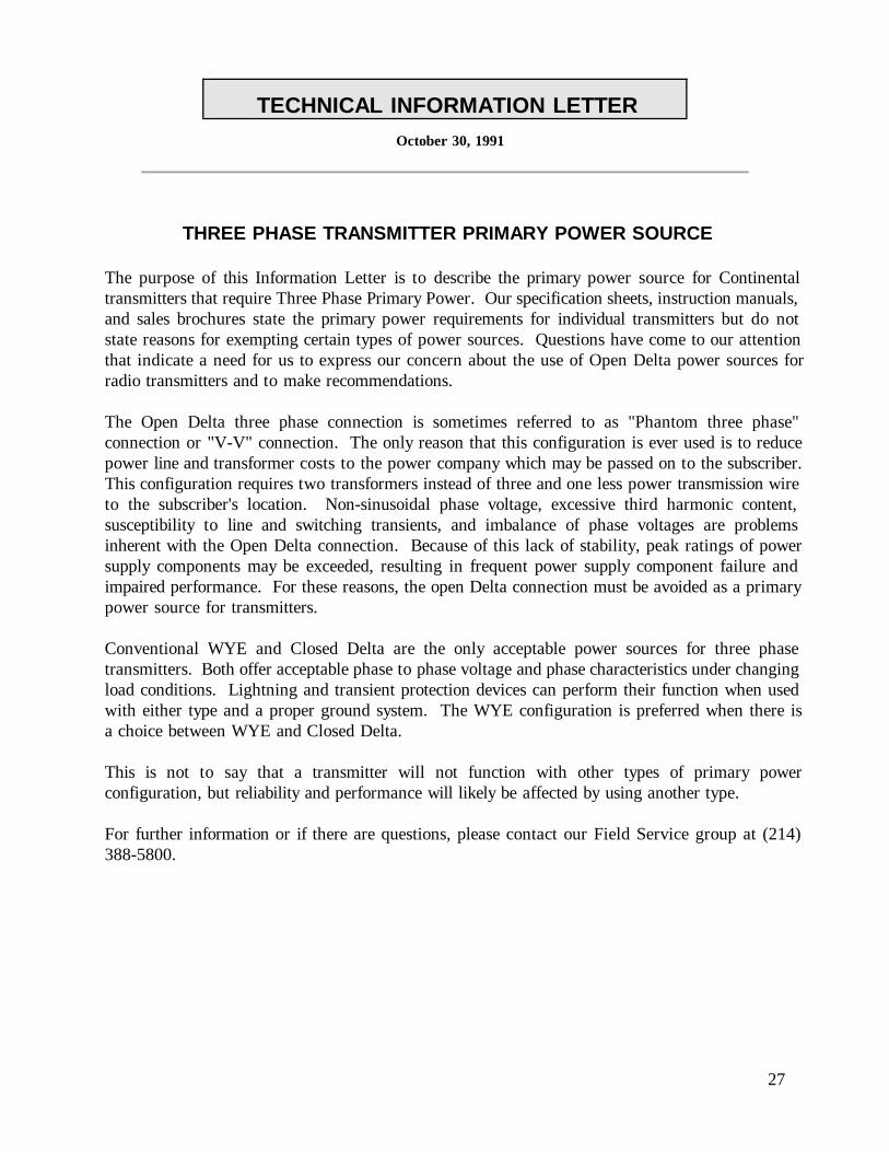
TECHNICAL INFORMATION LETTEROctober 30, 1991
THREE PHASE TRANSMITTER PRIMARY POWER SOURCE
The purpose of this Information Letter is to describe the primary power source for Continentaltransmitters that require Three Phase Primary Power. Our specification sheets, instruction manuals,and sales brochures state the primary power requirements for individual transmitters but do notstate reasons for exempting certain types of power sources. Questions have come to our attentionthat indicate a need for us to express our concern about the use of Open Delta power sources forradio transmitters and to make recommendations.
The Open Delta three phase connection is sometimes referred to as "Phantom three phase"connection or "V-V" connection. The only reason that this configuration is ever used is to reducepower line and transformer costs to the power company which may be passed on to the subscriber.This configuration requires two transformers instead of three and one less power transmission wireto the subscriber's location. Non-sinusoidal phase voltage, excessive third harmonic content,susceptibility to line and switching transients, and imbalance of phase voltages are problemsinherent with the Open Delta connection. Because of this lack of stability, peak ratings of powersupply components may be exceeded, resulting in frequent power supply component failure andimpaired performance. For these reasons, the open Delta connection must be avoided as a primarypower source for transmitters.
Conventional WYE and Closed Delta are the only acceptable power sources for three phasetransmitters. Both offer acceptable phase to phase voltage and phase characteristics under changingload conditions. Lightning and transient protection devices can perform their function when usedwith either type and a proper ground system. The WYE configuration is preferred when there isa choice between WYE and Closed Delta.
This is not to say that a transmitter will not function with other types of primary powerconfiguration, but reliability and performance will likely be affected by using another type.
For further information or if there are questions, please contact our Field Service group at (214)388-5800.
28
816R INFORMATION LETTERJanuary 18, 1992
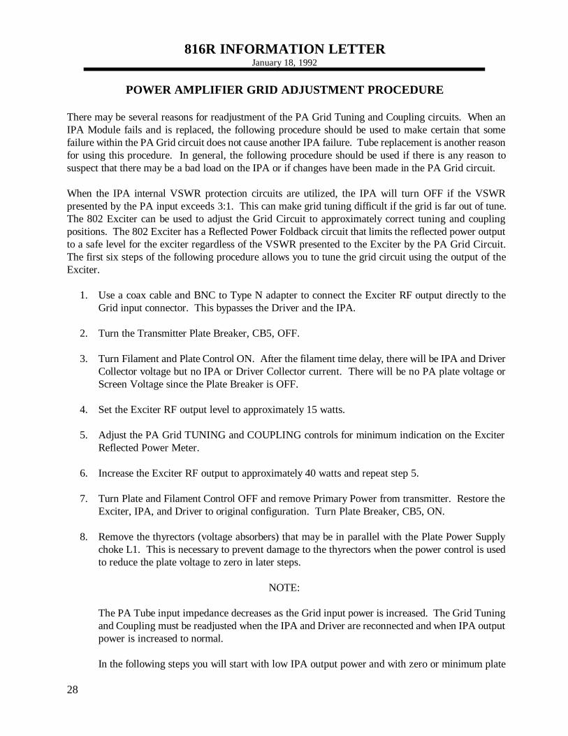
POWER AMPLIFIER GRID ADJUSTMENT PROCEDURE
There may be several reasons for readjustment of the PA Grid Tuning and Coupling circuits. When anIPA Module fails and is replaced, the following procedure should be used to make certain that somefailure within the PA Grid circuit does not cause another IPA failure. Tube replacement is another reasonfor using this procedure. In general, the following procedure should be used if there is any reason tosuspect that there may be a bad load on the IPA or if changes have been made in the PA Grid circuit.
When the IPA internal VSWR protection circuits are utilized, the IPA will turn OFF if the VSWRpresented by the PA input exceeds 3:1. This can make grid tuning difficult if the grid is far out of tune.The 802 Exciter can be used to adjust the Grid Circuit to approximately correct tuning and couplingpositions. The 802 Exciter has a Reflected Power Foldback circuit that limits the reflected power outputto a safe level for the exciter regardless of the VSWR presented to the Exciter by the PA Grid Circuit.The first six steps of the following procedure allows you to tune the grid circuit using the output of theExciter.
1. Use a coax cable and BNC to Type N adapter to connect the Exciter RF output directly to theGrid input connector. This bypasses the Driver and the IPA.
2. Turn the Transmitter Plate Breaker, CB5, OFF.
3. Turn Filament and Plate Control ON. After the filament time delay, there will be IPA and DriverCollector voltage but no IPA or Driver Collector current. There will be no PA plate voltage orScreen Voltage since the Plate Breaker is OFF.
4. Set the Exciter RF output level to approximately 15 watts.
5. Adjust the PA Grid TUNING and COUPLING controls for minimum indication on the ExciterReflected Power Meter.
6. Increase the Exciter RF output to approximately 40 watts and repeat step 5.
7. Turn Plate and Filament Control OFF and remove Primary Power from transmitter. Restore theExciter, IPA, and Driver to original configuration. Turn Plate Breaker, CB5, ON.
8. Remove the thyrectors (voltage absorbers) that may be in parallel with the Plate Power Supplychoke L1. This is necessary to prevent damage to the thyrectors when the power control is usedto reduce the plate voltage to zero in later steps.
NOTE:
The PA Tube input impedance decreases as the Grid input power is increased. The Grid Tuningand Coupling must be readjusted when the IPA and Driver are reconnected and when IPA outputpower is increased to normal.
In the following steps you will start with low IPA output power and with zero or minimum plate

29
voltage. You will adjust Grid Tuning and Coupling as you slowly increase drive power untilnormal drive power is reached and then you will slowly increase plate voltage while adjusting GridTuning and Coupling until normal operating plate voltage is reached. Keep the IPA ReflectedPower to a minimum as you make adjustments to IPA power output and plate voltage.
9. Restore primary power to the transmitter and turn the Filament control ON.
10. Set the Exciter Power Output Adjustment fully CCW.
11. Press the Exciter MUTE Switch. Turn Plate control ON and reduce the plate voltage to zeroor to minimum with the Manual Power Control.
12. Release the Exciter MUTE switch and slowly increase the Exciter output while watching theIPA Reflected Power. Do not let the IPA Reflected power exceed 60 watts.
13. Adjust the PA Grid Tuning and Coupling for minimum IPA Reflected Power as the Exciteroutput is increased to normal. DO NOT EXCEED 20 AMPERES ON IPA COLLECTORCURRENT. The normal range of IPA Collector current is 18 - 20 Amps.
14. Slowly increase the plate voltage with the Manual Power Control. You will notice that the IPAReflected Power will increase as the plate voltage is increased. Adjust the Grid Tuning andCoupling to keep the IPA Reflected Power at minimum as the plate voltage is increasedtoward maximum.
15. This completes the adjustment procedure. Restore the transmitter to normal configuration.
NOTE:
The 816R-2C, 3C, 4C, and 5C transmitters do not use the 150 watt driver and the normal exciteroutput will be in the range of 20 to 35 watts.
The Exciter RF output will be 10 watts if the IPA power output is controlled by the collectorvoltage on the 150 watt Driver. The Driver collector voltage and the IPA output is set byadjustment of R40 on the IPA Meter Board.
The Exciter output will be approximately seven watts if the IPA output is controlled by the ExciterRF Output Level Control only and the transmitter uses the 150 driver module.
Please contact Continental Technical Support at (214) 388-5800 if you have questions about thisInformation Letter.
4 4 4 4 4 4 4 4 4 4 4 4 4 4 4 4 4 4 4 4 4 4 4 4 4 4 4 4 4 4 4 4 4 4 4 4 4 4 4 4 4 4 4 4 4 4 4 4 4 4 4 UCONTINENTAL ELECTRONICS TECHNICAL SUPPORT PHONE (214)388-5800 FAX (214)381-7949
30
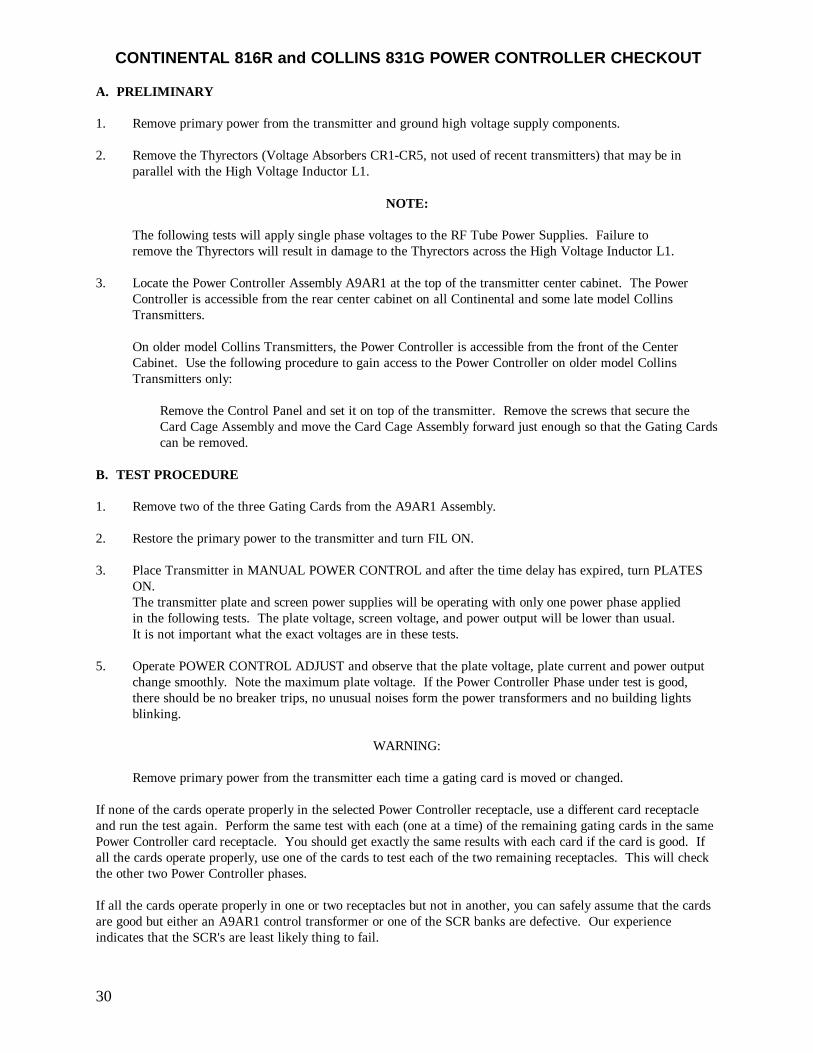
CONTINENTAL 816R and COLLINS 831G POWER CONTROLLER CHECKOUT
A. PRELIMINARY
1. Remove primary power from the transmitter and ground high voltage supply components.
2. Remove the Thyrectors (Voltage Absorbers CR1-CR5, not used of recent transmitters) that may be inparallel with the High Voltage Inductor L1.
NOTE:
The following tests will apply single phase voltages to the RF Tube Power Supplies. Failure toremove the Thyrectors will result in damage to the Thyrectors across the High Voltage Inductor L1.
3. Locate the Power Controller Assembly A9AR1 at the top of the transmitter center cabinet. The PowerController is accessible from the rear center cabinet on all Continental and some late model CollinsTransmitters.
On older model Collins Transmitters, the Power Controller is accessible from the front of the CenterCabinet. Use the following procedure to gain access to the Power Controller on older model CollinsTransmitters only:
Remove the Control Panel and set it on top of the transmitter. Remove the screws that secure theCard Cage Assembly and move the Card Cage Assembly forward just enough so that the Gating Cardscan be removed.
B. TEST PROCEDURE
1. Remove two of the three Gating Cards from the A9AR1 Assembly.
2. Restore the primary power to the transmitter and turn FIL ON.
3. Place Transmitter in MANUAL POWER CONTROL and after the time delay has expired, turn PLATESON.The transmitter plate and screen power supplies will be operating with only one power phase appliedin the following tests. The plate voltage, screen voltage, and power output will be lower than usual. It is not important what the exact voltages are in these tests.
5. Operate POWER CONTROL ADJUST and observe that the plate voltage, plate current and power outputchange smoothly. Note the maximum plate voltage. If the Power Controller Phase under test is good,there should be no breaker trips, no unusual noises form the power transformers and no building lightsblinking.
WARNING:
Remove primary power from the transmitter each time a gating card is moved or changed.
If none of the cards operate properly in the selected Power Controller receptacle, use a different card receptacleand run the test again. Perform the same test with each (one at a time) of the remaining gating cards in the samePower Controller card receptacle. You should get exactly the same results with each card if the card is good. Ifall the cards operate properly, use one of the cards to test each of the two remaining receptacles. This will checkthe other two Power Controller phases.
If all the cards operate properly in one or two receptacles but not in another, you can safely assume that the cardsare good but either an A9AR1 control transformer or one of the SCR banks are defective. Our experienceindicates that the SCR's are least likely thing to fail.
31
Drawings
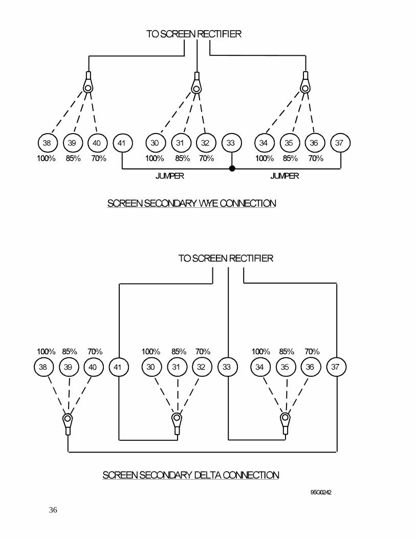
816R Power Amplifier Cavity . . . . . . . . . . . . . . . . . . . . . . . . . . . . . . . . . . . . . . . 32A5 Component Shelf Assembly . . . . . . . . . . . . . . . . . . . . . . . . . . . . . . . . . . . . . . 33SCR Assembly . . . . . . . . . . . . . . . . . . . . . . . . . . . . . . . . . . . . . . . . . . . . . . . . . . 34Primary Power Distribution . . . . . . . . . . . . . . . . . . . . . . . . . . . . . . . . . . . . . . . . . 35Screen Transformer Secondary Connections . . . . . . . . . . . . . . . . . . . . . . . . . . . . . 36
32
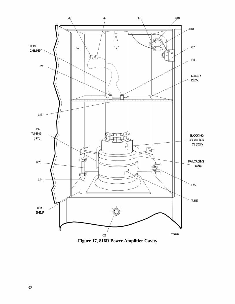
Figure 17, 816R Power Amplifier Cavity
33
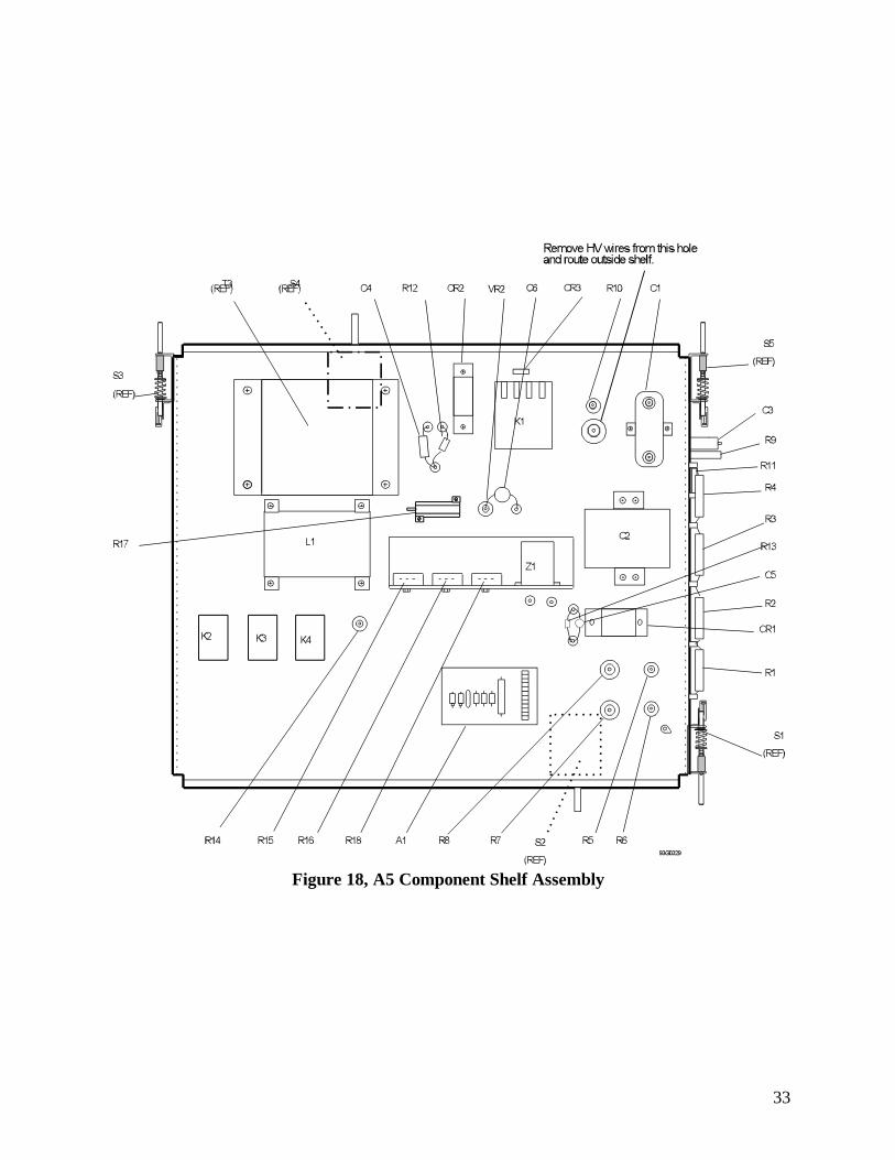
Figure 18, A5 Component Shelf Assembly
34
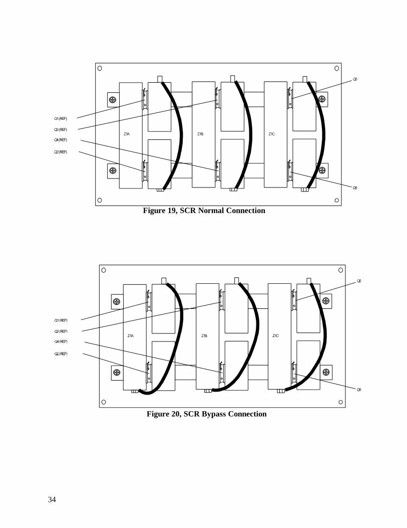
Figure 20, SCR Bypass Connection
Figure 19, SCR Normal Connection
35
Figure 21, Primary Power Distribution
36

37
YOUR COMMENTS PLEASE:
It is our goal to provide useful information to you and it is by our Customer’s suggestions and commentsthat we are able to improve our service and products. Please let us know what you think of this “TrainingManual” and this one day 816R Seminary and what are your suggestions for improvement?
Please send your comments and suggestions to:
or
FAX
Dave Chenoweth (214) 381-3250
or
Continental ElectronicsDave ChenowethP. O. Box 270879
4212 South Buckner BlvdDallas, TX 75227