Embed Size (px)
Citation preview
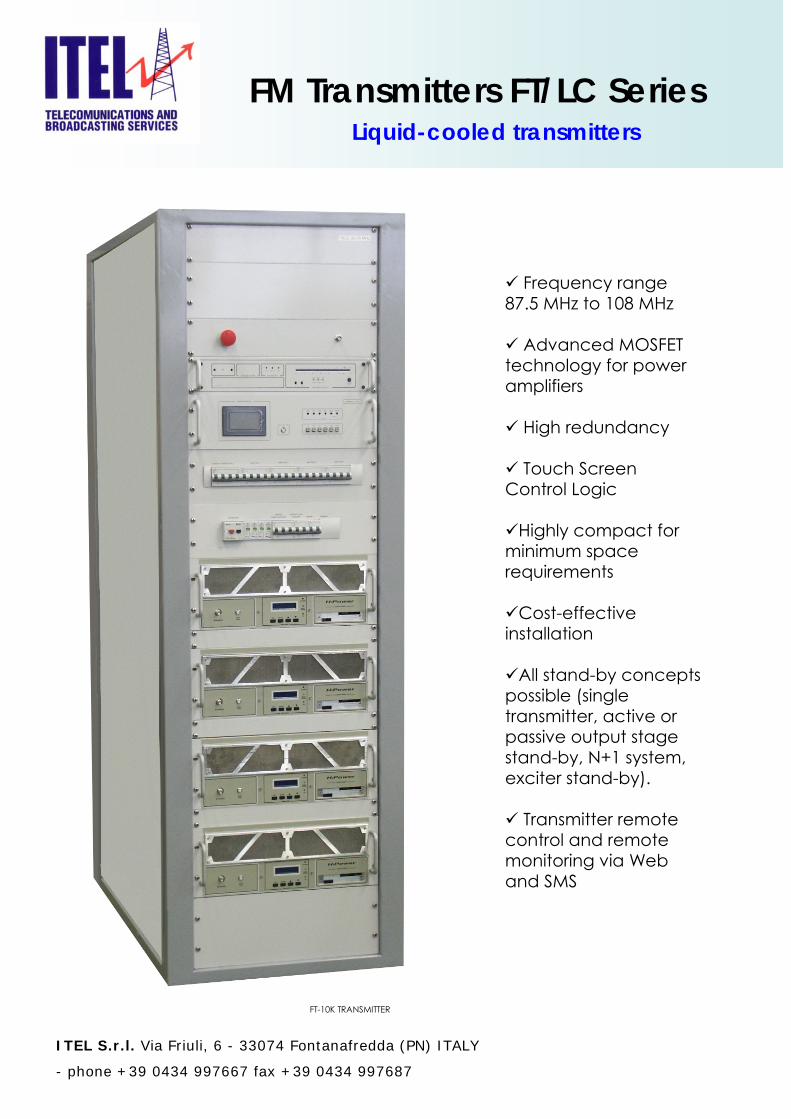
FM Transmitters FT/LC SeriesLiquid-cooled transmitters
Frequency range 87.5 MHz to 108 MHz
Advanced MOSFET technology for power amplifiers
High redundancy
Touch Screen Control Logic
Highly compact for minimum space requirements
Cost-effective installation
All stand-by concepts possible (single transmitter, active or passive output stage stand-by, N+1 system, exciter stand-by).
Transmitter remote control and remote monitoring via Web and SMS
ITEL S.r.l. Via Friuli, 6 - 33074 Fontanafredda (PN) ITALY
- phone +39 0434 997667 fax +39 0434 997687
FT-10K TRANSMITTER
Description
The FM Transmitter series FT from ITEL is a new generation of air cooled transmitters for FM transmission. Each transmitter consists of the following main components:
Single Driver (Dual on request)Power RF Amplifiers included power
supplyMicroprocessor transmitter controlLow Pass Filter
The range of power of the new generation of FM transmitters varies from 700W up to 40kW.
All transmitter can be equipped with a second Driver and the associated automatic switch-over unit (Option).
Protection against
Overload and short-circuits.Inefficiency of the cooling system.Missing mains AC (phase control).Automatic reduction of the RF output power in real time for excessive VSWR.RF amplifier over drive.
Options
Dual DriverSerial interface IEC 864-2Stereo (IRT – NICAM – BTSC).Dual Mains AC input line.Interactive control with data storage(data can be elaborated by PC).
General characteristics
Very compact size: simplifies transportation and installation.Modular design: increases reliability and simplifies maintenance operation.Low operating cost.RF output obtained from the parallel of the amplifiers modules, each module with its own individual power supply to maximize the reliability.High performance linearity corrector.Very high MTBF.Broadband RF amplifiers, full band coverage without any adjustment.Synthesized local oscillator.
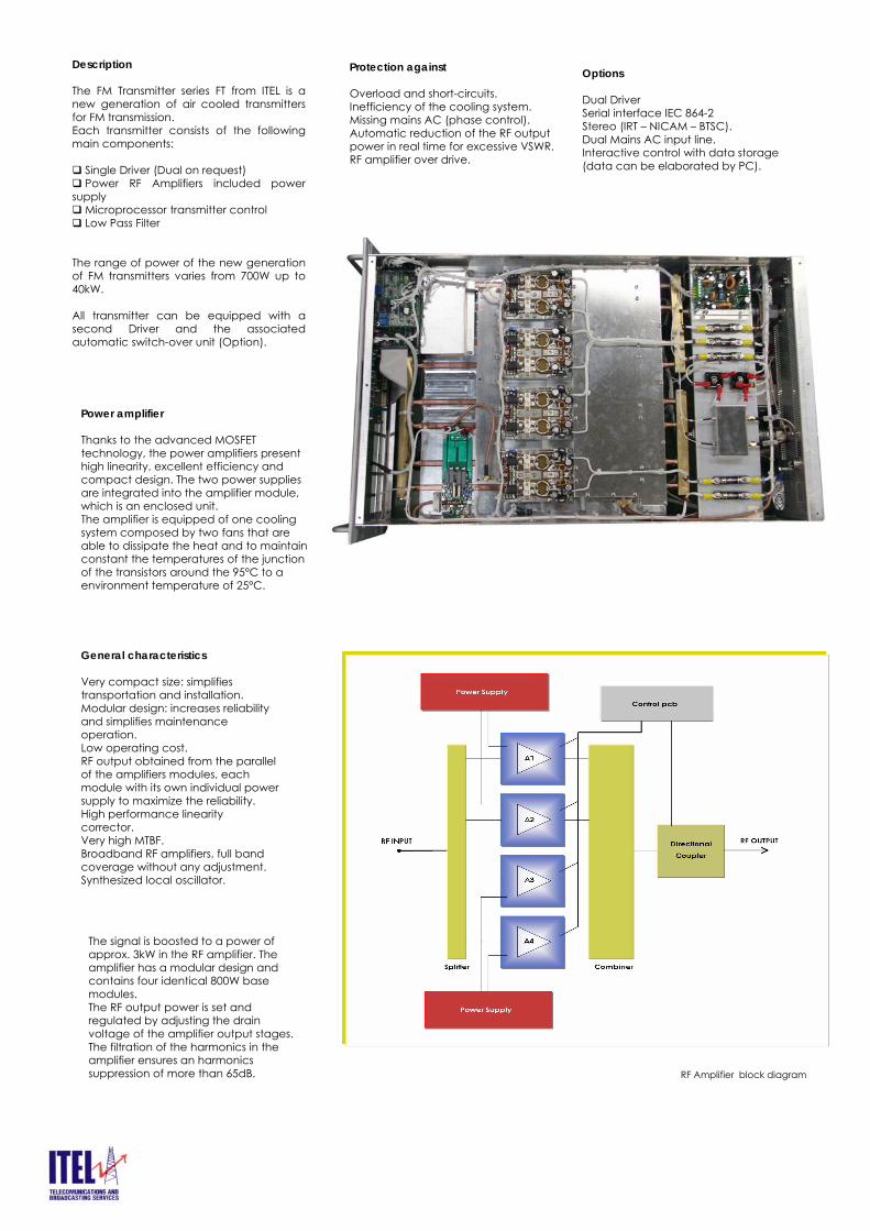
Power amplifier
Thanks to the advanced MOSFET technology, the power amplifiers present high linearity, excellent efficiency and compact design. The two power supplies are integrated into the amplifier module, which is an enclosed unit. The amplifier is equipped of one cooling system composed by two fans that are able to dissipate the heat and to maintain constant the temperatures of the junction of the transistors around the 95°C to a environment temperature of 25°C.
The signal is boosted to a power of approx. 3kW in the RF amplifier. The amplifier has a modular design and contains four identical 800W base modules.The RF output power is set and regulated by adjusting the drain voltage of the amplifier output stages. The filtration of the harmonics in the amplifier ensures an harmonics suppression of more than 65dB. RF Amplifier block diagram
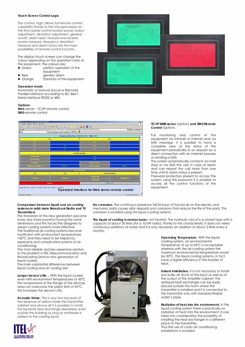
Operated Interface for Web server remote control
TC/IP WEB server (option) and SMS Remote Control (option).
Full monitoring and control of the equipment via Intranet or Internet and via SMS message. It is possible to have a complete view of the status of the equipment periodically or on request by a direct connection with an Internet browser or sending a SMS. The system automatically contacts via mail (fax) or via SMS the user in case of alarm and can repeat the call more than one time until its alarm status is present. Password protection present to access the system: using this password it is possible toaccess all the control functions of the equipment.
Touch Screen Control Logic
The control logic allows full remote control capability thanks to the microprocessor on the front panel control board: power output adjustment, deviation adjustment, general on/off, alarm reset, forward and reverse power measure, frequency deviation measure and alarm status are the main possibilities of remote control function.
The display touch screen can change the colour depending on the operation state of the equipment. The colours are: Green perfect operation of the
equipment Red generic alarm Orange Stand-by of the equipment
Operation modeAutomatic or Manual (Local or Remote)Parallel interface according to IEC 864-1.Serial interface RS232 or 485.
OptionsWeb server – TC/IP remote control SMS remote control
Comparison between liquid and air-coolingsystems in solid-state Broadcast Radio and TV TransmittersThe transistors of the new generation becomeevery day more powerful having the samedimensions and this forces the designers toadopt cooling systems more effective. The traditional air cooling systems becomeinsufficient with environment temperatures>30°C and they need to be helped byexpensive and complicated systems of air conditioning.The most reliable and less expensive solutionto this problem is ITEL Telecommunication and Broadcasting Service new generation of liquid coolers.The main substantial differences between liquid cooling and air cooling are:
Longer device’s life .. With the liquid coolerseven with environment temperatures of 45°C the temperature of the flange of the devicesdoes not overcome the safety limit of 55°C, this increases the device’s life.
Acoustic Noise. This is very low because of the absence of airflow inside the transmitter cabinet and above all it is possible to install the liquid/air heat exchange elsewhere; even outside the building as long as antifreeze is added to the cooling liquid.
Operating Temperature. With the liquidcooling system, an environmentaltemperature of up to 45°C is acceptablewhereas with the air-cooling system the maximum environmental temperature wouldbe 30°C. The liquid cooling systems, in fact, have a higher efficiency in the transfer of heat.
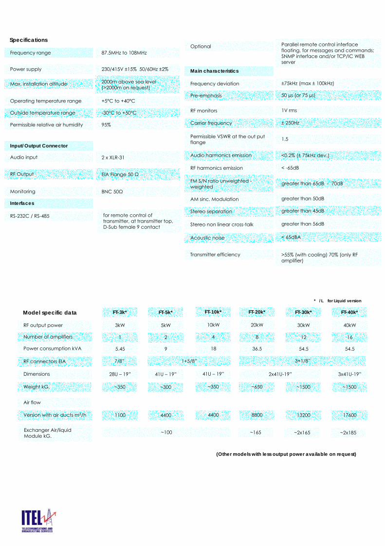
Instant installation. It is not necessary to installany bulky air ducts at the input as well as at the output of the Amplifier cabinet. The air/liquid heat exchanger can be easilyplaced outside the room where the transmitter is installed and it is connected tothe transmitter only with standard flexiblewater’s pipes.
Radiation of heat into the environment. In the liquid cooling system there is practically no radiation of heat into the environment, if one takes into consideration the possibility of installing the heat exchanger in a different place to the transmitter. Thus the use of costly air conditioning installations is avoided.
No corrosion. The continuous presence 24/24 hours of forced air on the electric and mechanic parts causes salty deposits and corrosions that reduce the life of the parts. Thiscorrosion is avoided using the liquid cooling systems.
The liquid of cooling is normal water, not treated. The hydraulic circuit is a closed type with a capacity of about 30 litres (for a 10 kW radio): thanks to this characteristic it does not needcontinuous additions of water and it is only necessary an addition of about 2 litres every 6 months.
Specifications
Frequency range
Power supply
Max. installation altitude
Operating temperature range
Outside temperature range
Permissible relative air humidity
Input/Output Connector
Audio input
RF Output
Monitoring
Interfaces
RS-232C / RS-485
87.5MHz to 108MHz
230/415V ±15% 50/60Hz ±2%
2000m above sea level (>2000m on request)
+5°C to +40°C
-30°C to +50°C
95%
2 x XLR-31
EIA Flange 50 Ω
BNC 50Ω
for remote control of transmitter, at transmitter top, D-Sub female 9 contact
Optional
Main characteristics
Frequency deviation
Pre-emphasis
Transmitter efficiency
Parallel remote control interface floating, for messages and commands; SNMP interface and/or TCP/IC WEB server
±75kHz (max ± 100kHz)
50 µs (or 75 µs)
>55% (with cooling) 70% (only RF amplifier)
RF output power
Number of amplifiers
Dimensions
RF connectors EIA
FT-3k* FT-5k* FT-10k* FT-20k* FT-30k*
3kW 5kW 10kW 20kW 30kW
1 2 4 8 12
28U – 19” 41U – 19” 41U – 19” 2x41U-19”
7/8” 1+5/8”
Model specific data
RF monitors
Carrier frequency
1V rms
± 250Hz
Permissible VSWR at the out put flange 1.5
Audio harmonics emission <0.2% (± 75kHz dev.)
RF harmonics emission < -65dB
AM sinc. Modulation
Stereo separation
greater than 50dB
greater than 45dB
Stereo non linear cross-talk greater than 56dB
Acoustic noise < 65dBA
Weight kG. ~350 ~300 ~350 ~650 ~1500
Power consumption kVA 5.45 9 18 36.5 54.5
FM S/N ratio unweighted -weighted greater than 65dB - 70dB
3+1/8”
Version with air ducts m3/h 1100 4400 4400 8800 13200
Air flow
FT-40k*
40kW
16
3x41U-19”
~1500
54.5
17600
Exchanger Air/liquid Module kG.
~100 ~165 ~2x165 ~2x185
* /L for Liquid version
(Other models with less output power available on request)