Embed Size (px)
Citation preview

Transmission System Modeling Data Requirements and Reporting Procedures
In Accordance with NERC Reliability Standard MOD-032-1 “Data for Power System Modeling and Analysis”
Originator: Hydro-Québec TransÉnergie
Direction Planification Effective date: July 1, 2015 Revision: 4 (November 2020)


Hydro-Québec TransÉnergie
Table of Contents
Revision History ........................................................................................................................... 5
1. Application ......................................................................................................................... 7
1.1 Objective ...........................................................................................................................................7
1.2 Scope ................................................................................................................................................7
1.3 Data Confidentiality .........................................................................................................................9
2. Power System Modeling ...................................................................................................10
2.1 Development of Power System Models .........................................................................................10
2.2 Functional Entities within the Québec Interconnection ..................................................................10
2.3 Power System Modeling Workflow ...............................................................................................11
2.3.1 Modeling Workflow Diagram .............................................................................................11
2.3.2 Description of Power System Modeling Activities .............................................................13
3. Generating Facility Modeling ...........................................................................................15
3.1 Modeling Data Requirements .........................................................................................................15
3.1.1 Steady-State Data for Modeling and Simulation of the Interconnected Transmission System. 16
3.1.2 Short-Circuit and Dynamics Data Requirements for Power Station Modeling ..................17
3.2 Data Reporting Requirements ........................................................................................................19
3.2.1 Data Format .........................................................................................................................19
3.2.2 Data Submission Procedure and Schedule ..........................................................................20
4. Transmission System Equipment Modeling ...................................................................21
4.1 Modeling Data Requirements .........................................................................................................21
4.1.1 Steady-State Data for Modeling Transmission Systems .....................................................22
4.1.2 Transmission System Equipment Dynamics and Short-Circuit Data Reporting Requirements ........................................................................................................................................24
4.1.3 Additional modeling data needed to calculate DC currents during geomagnetic storms ....26
4.2 Data Reporting Requirements ........................................................................................................27
4.2.1 Data Format .........................................................................................................................27
4.2.2 Data Submission Procedure and Schedule ..........................................................................28
5. Modeling of Demand .........................................................................................................29
5.1 Modeling Data Requirements .........................................................................................................29
5.1.1 Steady-State Data Requirements for Demand Modeling ....................................................29
5.1.2 Short-Circuit and Dynamics Data Requirements for Demand Modeling ...........................30
5.2 Data Reporting Requirements ........................................................................................................31
5.2.1 Data Format .........................................................................................................................31
5.2.2 Data Submission Procedure and Schedule ..........................................................................31

6. Complementary Power System Information ................................................................... 32
6.1 Resource Plan Data ........................................................................................................................ 32
6.1.1 Resource Planning Data Requirements .............................................................................. 32
6.1.2 Data Format ........................................................................................................................ 32
6.1.3 Data Submission Procedure and Schedule ......................................................................... 32
6.2 Interchange Schedule ..................................................................................................................... 32
6.2.1 Interchange Data Requirements ......................................................................................... 33
6.2.2 Data Format ........................................................................................................................ 33
6.2.3 Data Submission Procedure and Schedule ......................................................................... 33
7. Data Submission Procedure and Schedule .................................................................... 34
7.1 Data Submission Procedure ........................................................................................................... 34
7.2 Data Submission Schedule ............................................................................................................. 34
7.3 Non-Compliances .......................................................................................................................... 35
APPENDIX 1 – List of Accepted Dynamics Models .................................................................. 36

Hydro-Québec TransÉnergie
Transmission System Modeling Data Requirements and Reporting Procedures 5
Revision History
1 In order to allow entities sufficient time to adapt their practice, for the first data submission exercise following the
publication of the present document (2021 data submission), an entity may choose to submit their data according to the
former schedule.
Revision no.
Section Revision Description Date
0 Original version December 16, 2015
1 All sections General revision of document April 15, 2016
2 1, 2.1, 2.2, 2.3.2, 3.1, 4.1, 5.1,
6.1.1, 6.2.1, 7.3,
References, Appendices 1, 4 and 6
Revised text
Added Revision History
Added Scope and Data Confidentiality sections
Modified list of functional entities
Revised requirements for modeling data for generation facilities, transmission equipment and demand
Added requirements for the modeling data needed to calculate DC currents during geomagnetic storms
Revised templates in Appendices 1, 4 and 6
March 30, 2017
3 All sections Corrected minor errors
Removed Subsections i and ii of Section 5.1.1 to prevent redundancy
Modification related to the concept of load aggregation (Section 5)
Removed reference to standard PRC-006-NPCC, which is not in effect in Québec (Section 5)
Corrected the e-mail address for sending data (Section 7)
Modified data submission dates to reflect current procedures (Section 7)
Added a provision for entities to request an extension to the data submission deadline (Section 7)
Added the GENTPJ dynamic generator model to the list of approved models (Appendix 2)
May 31, 2018
4 Corrected minor errors
Removed section 2.3.3
Modification regarding accepted dynamic models. User-defined models vs generic models.(section 3.1.2)
Removed information about bus numbering convention, these numbers being attributed by the PC (section 4.1.1)
Added precisions on impedances to be provided. Positive and negative sequence and mutual impedances in compliance with appendix 1 of the standard. (section 4.1.2)
Modified data submission schedule1 (section 7.2)
November 2020

Hydro-Québec TransÉnergie
Transmission System Modeling Data Requirements and Reporting Procedures 6
Removed provision for entities to request an extension to the data submission deadline. This provision was not in compliance with the standard. (section 7.3)
Removed redundant appendices
Modified list of accepted models (Appendix 1)
Hydro-Québec TransÉnergie
Transmission System Modeling Data Requirements and Reporting Procedures 7
1. Application
1.1 Objective
Hydro-Québec TransÉnergie (HQT), in its role as Planning Coordinator and Transmission Planner,
is charged with the task of maintaining transmission system models (steady-state, dynamics, and
short-circuit) and developing power flow and dynamics cases necessary to support planning studies
and reliability analysis of Québec’s interconnected transmission system. The accuracy of system
models is heavily dependent on the reliability of modeling data collected from the various functional
entities that interface with the transmission system.
The purpose of this document is to establish steady-state, dynamics, and short-circuit modeling data
requirements and reporting procedures, in accordance with NERC’s MOD-032 reliability standard,
“Data for Power System Modeling and Analysis.” The document shall serve as a reference guide to
all functional entities that provide data necessary for system modeling, providing the basic
requirements regarding the type of data required as well as applicable data submission procedures.
It will also describe how entities shall reference and use existing HQT technical documents and
procedures to meet modeling data requirements.
The most updated version of the present document shall be made available to all concerned
functional entities by means of an online posting on HQT’s website, via the following link:
http://www.hydroquebec.com/transenergie/en/modeling.html.
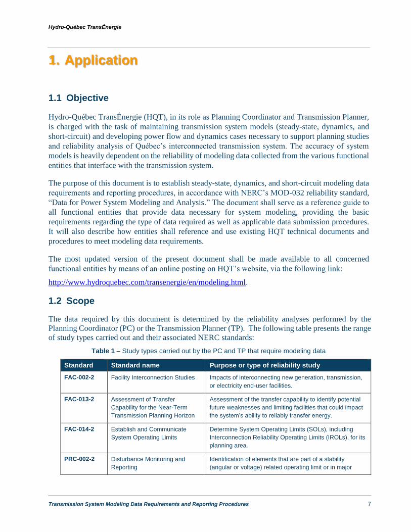
1.2 Scope
The data required by this document is determined by the reliability analyses performed by the
Planning Coordinator (PC) or the Transmission Planner (TP). The following table presents the range
of study types carried out and their associated NERC standards:
Table 1 – Study types carried out by the PC and TP that require modeling data
Standard Standard name Purpose or type of reliability study
FAC-002-2 Facility Interconnection Studies Impacts of interconnecting new generation, transmission,
or electricity end-user facilities.
FAC-013-2 Assessment of Transfer
Capability for the Near-Term
Transmission Planning Horizon
Assessment of the transfer capability to identify potential
future weaknesses and limiting facilities that could impact
the system’s ability to reliably transfer energy.
FAC-014-2 Establish and Communicate
System Operating Limits
Determine System Operating Limits (SOLs), including
Interconnection Reliability Operating Limits (IROLs), for its
planning area.
PRC-002-2 Disturbance Monitoring and
Reporting
Identification of elements that are part of a stability
(angular or voltage) related operating limit or in major

Hydro-Québec TransÉnergie
Transmission System Modeling Data Requirements and Reporting Procedures 8
Standard Standard name Purpose or type of reliability study
voltage sensitive areas. These elements will be equipped
with dynamic disturbance recorders.
PRC-006-3 Automatic Underfrequency Load
Shedding
Development and assessment of the Underfrequency
Load Shedding Program (UFLS). Analysis of the UFLS
program during underfrequency events.
PRC-006-
NPCC-2
Automatic underfrequency load
shedding
Development and assessment of the Underfrequency
Load Shedding Program (UFLS).
PRC-010-2 Undervoltage Load Shedding Development (as required) and periodic assessment of an
undervoltage load shedding (UVLS) program. Analysis of
the UVLS program during events causing undervoltage
conditions.
PRC-023-3 Transmission Relay Loadability Identification of circuits for which protective relay settings
must be adjusted to prevent transmission system
loadability limiting.
PRC-026-1 Relay Performance During Stable
Power Swings
Identification of the generating units, transformers and
transmission lines where an angular stability constraint
exists.
TPL-001-4 Transmission System Planning
Performance Requirements
Annual planning assessment: Documented evaluation of
future Transmission System performance and Corrective
Action Plans to remedy identified deficiencies.
TPL-007-4 Transmission System Planned
Performance for Geomagnetic
Disturbance Events
Periodic assessment of geomagnetic disturbance (GMD)
vulnerability.
The system models prepared by the PC are also used by the Transmission Operator (TOP) and
Balancing Authority (BA) in the system simulations explicitly required by some standards or
implicitly required for the development of operating strategies and plans. The following table
presents these reliability study types and their associated NERC standards:
Table 2 – Study types carried out by the TOP require modeling data
Standard Standard name Purpose or type of reliability study
EOP-005-3 System Restoration from
Blackstart Resources
Steady state and dynamic simulations to validate the
restoration plan.
FAC-014-2 Establish and Communicate
System Operating Limits
Identification of System Operating Limits (SOLs) and
Interconnection Reliability Operating Limits (IROLs).
MOD-029-2a Rated System Path Methodology Calculation of the Total Transfer Capacity (TTC) for paths
published in OASIS.

Hydro-Québec TransÉnergie
Transmission System Modeling Data Requirements and Reporting Procedures 9
1.3 Data Confidentiality
Data exchanged for the purposes of the requirements set out in this document and the requirements
of MOD-032 are considered confidential by the recipient entities, including the PC and the TP.
Furthermore, all data submitted to the NPCC is subject to the confidentiality provisions in Section
1500 of the North American Electric Reliability Corporation Rules of Procedure and is generally
aggregated in a non-identifiable manner with the data of other functional entities. While the primary
objective of this document is to allow the exchange of data required for modeling and reliability
analyses, any data sent to the PC or TP that is subject to a confidentiality request will be treated as
confidential by the receiving entity.

Hydro-Québec TransÉnergie
Transmission System Modeling Data Requirements and Reporting Procedures 10
2. Power System Modeling
Power flow and dynamics cases are developed by the Planning Coordinator (PC) in order to
realistically simulate the steady-state and dynamic performance of the Québec interconnected
transmission system. All electrical elements that comprise the transmission system, such as
generating units, power lines, transformers, reactive power compensation equipment, and system
loads, are modeled based on measured electrical parameters (modeling data) provided by various
functional entities within or connected to the transmission system.
2.1 Development of Power System Models
Power flow and dynamics cases are developed using the Siemens Power Technologies Inc. (PTI)
Power System Simulator for Engineers (PSS/E) simulation software (Siemens-PTI). A power flow
case is a collection of models that reproduce the steady-state system consisting of its generation and
transmission equipment, a given system topology, and the short-circuit, load, distribution and power
interchange data that constitute a snapshot of a specific combination of operating conditions. A
dynamics case is a collection of models of dynamic system response used in conjunction with a
power flow case to perform a stability analysis of system performance.
The PC develops a series of power flow and dynamics cases (also referred to as base cases) on an
annual basis, reflecting various system conditions and planning scenarios. These cases are used by
the PC and Transmission Planners (TPs) for system studies and reliability analysis. They are also
used by the NPCC through its SS-37 Working Group on Base Case Development. Consequently,
the accuracy of studies and reliability of base cases are heavily dependent on the quality of modeling
data collected from functional entities.
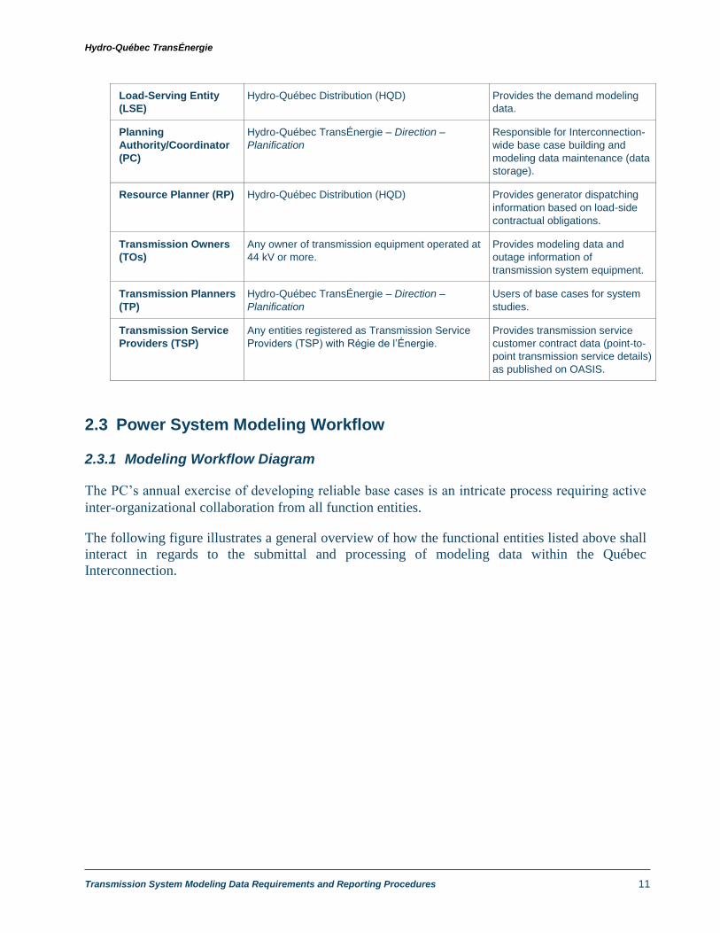
2.2 Functional Entities within the Québec Interconnection
The functional entities, as per MOD-032-1 (part A, section 4.1 “Applicability”), that play key roles
in obtaining, submitting, validating, and maintaining modeling data within the Québec
Interconnection are defined in the following table.
Table 3 – MOD-032-1 Functional Entities
Functional Entity2 Application Role in Power System Modeling
Generator Owners
(GOs)
Any owner of generation facilities (hydroelectric,
biomass, fossil fuel, wind, etc.) connected to the
transmission system
Provides modeling data for
generating units and generation
outage information.
2 This table is for information purposes only. The full list of the entities subject to reliability standards in Québec is
available on the Régie de l’Énergie Web site:
http://www.regie-energie.qc.ca/en/audiences/NormesFiabiliteTransportElectricite/RegistreEntites.html.
Hydro-Québec TransÉnergie
Transmission System Modeling Data Requirements and Reporting Procedures 11
Load-Serving Entity
(LSE)
Hydro-Québec Distribution (HQD) Provides the demand modeling
data.
Planning
Authority/Coordinator
(PC)
Hydro-Québec TransÉnergie – Direction –
Planification
Responsible for Interconnection-
wide base case building and
modeling data maintenance (data
storage).
Resource Planner (RP) Hydro-Québec Distribution (HQD) Provides generator dispatching
information based on load-side
contractual obligations.
Transmission Owners
(TOs)
Any owner of transmission equipment operated at
44 kV or more.
Provides modeling data and
outage information of
transmission system equipment.
Transmission Planners
(TP)
Hydro-Québec TransÉnergie – Direction –
Planification
Users of base cases for system
studies.
Transmission Service
Providers (TSP)
Any entities registered as Transmission Service
Providers (TSP) with Régie de l’Énergie.
Provides transmission service
customer contract data (point-to-
point transmission service details)
as published on OASIS.
2.3 Power System Modeling Workflow
2.3.1 Modeling Workflow Diagram
The PC’s annual exercise of developing reliable base cases is an intricate process requiring active
inter-organizational collaboration from all function entities.
The following figure illustrates a general overview of how the functional entities listed above shall
interact in regards to the submittal and processing of modeling data within the Québec
Interconnection.

Hydro-Québec TransÉnergie
Transmission System Modeling Data Requirements and Reporting Procedures 12
Figure 1 – Planning Coordinator Modeling Data Workflow

Hydro-Québec TransÉnergie
Transmission System Modeling Data Requirements and Reporting Procedures 13
2.3.2 Description of Power System Modeling Activities
As illustrated above, power system modeling is comprised of a sequence of modeling data
submission, validation and processing activities required to produce interconnection-wide base cases
suitable for system studies. Modeling data is collected from various functional entities, validated to
ensure functionality and compatibility with simulation tools, and then entered into specific data bases
for referencing and base case building.
Essentially, case building is achieved based on the following inputs:
1. Steady-state and Short-circuit Modeling Data from PSS® Model on Demand (MOD)
Database
The MOD database consolidates all generation and transmission system steady-state and
short-circuit modelling data (including planned future projects) collected from various
functional entities in a central data repository. MOD is synched with DSR, the PC’s main
equipment data base containing updated modeling data of all existing generating and
transmission system facilities, producing a MOD base case scenario in PSS/E format (.sav).
Future projects, consisting of generation or transmission system additions, upgrades or
modifications, are submitted to the PC by TPs and stored in MOD. They are then applied to
the MOD base case scenario, allowing the PC and TPs to customize planning cases for any
desired future point in time.
Corrections or modifications to modeling data for existing facilities are validated before data
is updated in the DSR database. In the case of future projects, preliminary modeling data
submitted by GOs, TOs and TPs are entered directly into MOD, after model validation by the
PC. New generating units or transmission system equipment are only added to DSR after
project commissioning and after the PC has received all updated modeling data. This updated
data is obtained from GOs and TOs at the later stages of the project commissioning phase.
2. Dynamics Models and Modeling Parameters
Validated dynamics models and modeling parameters of existing facilities and future projects
collected from GOs, TOs and TPs are stored in the PC’s dynamics library. The PC’s dynamics
library consists of all dynamics model files required to run dynamics simulations in PSS/E
(*.lib, *.obj, *.dll, etc.), source code files for certain user-defined models, dynamics
parameters in the form of DYR files, and any IDEV or PYTHON programs necessary to set
up dynamics simulation parameters.
3. Demand Data
Once aggregate demand data for each load is received from the LSE, the PC validates and
processes the data, mapping load data to the appropriate load serving buses in the MOD base
case. The validated data is then stored in the PC’s Load Forecast Database which is used to
produce load profiles for a given forecast year in the form of PYTHON automation files.
Hydro-Québec TransÉnergie
Transmission System Modeling Data Requirements and Reporting Procedures 14
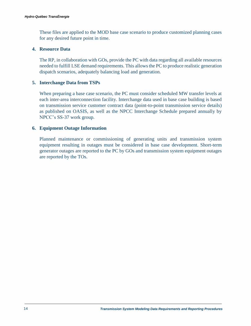
These files are applied to the MOD base case scenario to produce customized planning cases
for any desired future point in time.
4. Resource Data
The RP, in collaboration with GOs, provide the PC with data regarding all available resources
needed to fulfill LSE demand requirements. This allows the PC to produce realistic generation
dispatch scenarios, adequately balancing load and generation.
5. Interchange Data from TSPs
When preparing a base case scenario, the PC must consider scheduled MW transfer levels at
each inter-area interconnection facility. Interchange data used in base case building is based
on transmission service customer contract data (point-to-point transmission service details)
as published on OASIS, as well as the NPCC Interchange Schedule prepared annually by
NPCC’s SS-37 work group.
6. Equipment Outage Information
Planned maintenance or commissioning of generating units and transmission system
equipment resulting in outages must be considered in base case development. Short-term
generator outages are reported to the PC by GOs and transmission system equipment outages
are reported by the TOs.

Hydro-Québec TransÉnergie
Transmission System Modeling Data Requirements and Reporting Procedures 15
3. Generating Facility Modeling
3.1 Modeling Data Requirements
All Generator Owners (GOs) connected to the Québec interconnected transmission system must
provide valid modeling data of existing and future generating units to the PC on an annual basis.
Planned generation facilities are defined as new generating station projects that are subject to a
connection agreement.
The PC also requires GOs of existing facilities to recertify generator modeling data on an annual
basis, either by resubmitting all required modeling data or by certifying that data has not changed
from the previous year’s data submission. In the case of changes to modeling data, GOs must clearly
identify all changes and submit all modified modeling data in accordance with the requirements
herein.
For planned generating facilities, modeling data is generally submitted at three times: 1) during the
study phase, 2) after generating station commissioning, and 3) during the annual generating facility
modeling data submission period.
1 – Study phase
The PC and TPs initially collect approximated generator modeling data from new and
prospective GOs in order to conduct interconnection or system impact studies prior to
commissioning of generating facilities. This preliminary data is submitted to the PC and the TPs
using Appendices A and B of the HQT document entitled “Transmission Provider Technical
Requirements for the Connection of Power Plants to the Hydro-Québec Transmission System”
(hereinafter “HQT connection requirements”), available on HQT’s website at:
http://www.hydroquebec.com/transenergie/fr/commerce/pdf/2_Exigences_raccordement_centr
ales_D-2018-145_2018-11-15.pdf
Normally, this data is submitted when a GO requests an impact study for the connection of a
new generating station. The connection procedure for new generating units is available (in
French) on HQT’s website at:
http://www.hydroquebec.com/transenergie/fr/commerce/pdf/demarche-a-suivre-2012.pdf.
2 – Commissioning
GOs shall update the preliminary data provided to the PC and TPs during the project study and
draft-design phases by providing actual or measured modeling parameters. GOs must validate
modeling data as well as demonstrate that their facilities meet the requirements set out in the
HQT connection requirements.

Hydro-Québec TransÉnergie
Transmission System Modeling Data Requirements and Reporting Procedures 16
The validation of modeling data is a prerequisite for final TO acceptance of the generating facility
project and must be completed within 6 months of initial commercial commissioning.
The validation procedures and testing for wind farms are outlined in HQT’s “General Validation
Test Program for Wind Power Plants Connected to the Hydro-Québec Transmission System”
document, available on HQT’s website at:
http://www.hydroquebec.com/transenergie/fr/commerce/pdf/essais-eoliennes2011-fr.pdf.
3 – Annual submission
Planned generating facilities must be included in the GO’s annual modeling data submission
once the generating station project has been confirmed. This confirmation is received through a
connection agreement between the GO and HQT.
The following sections present the steady-state, dynamics and short-circuit data required to
effectively model all generating units within the Québec interconnected transmission system,
defining the type of data required and the units this data is to be reported in.
3.1.1 Steady-State Data for Modeling and Simulation of the Interconnected
Transmission System.
i. The table below summarizes the main steady-state data requirements, as outlined in MOD-
032-1, A1-3.
Table 4 – Steady-state data requirements
for generating facilities
Generating Equipment Steady-State Modeling Data
Synchronous or asynchronous
generators
Type of generation (e.g., thermal, wind or hydropower)
Real power capabilities (maximum and minimum values in
MW)
Reactive power capabilities (maximum and minimum values in
MVAR)
Nominal MVA base
Ratings
Generator unit regulated bus and set point voltage
Machine grounding impedances
In-service status
Generating station step-up
transformers1
Number of transformers
Nominal voltages of windings (kV)
Rated power (MVA)
Power ratings (MVA) with corresponding cooling method
Ratings
Positive sequence impedances and winding resistance (Ohms
or p.u.)
1 Data to be provided by the owner of the transformer, which may be the GO or the TO.

Hydro-Québec TransÉnergie
Transmission System Modeling Data Requirements and Reporting Procedures 17
Generating Equipment Steady-State Modeling Data
Coupling (i.e., winding connection)
Number of tap positions (kV or p.u.)
Tap ratios (voltage or phase angle)
Regulation range (minimum and maximum tap positions)
Regulated bus (for voltage regulated transformers)
In-service status
Wind farm collector system Zero sequence impedance parameters, R and X (ohms or p.u.)
Transmission line admittance (Siemens or p.u.)
Transmission line ratings (MVA or A)
Facility Ratings
Reactive compensation equipment data (capacitors and
reactors), i.e., number, in-service status, nominal reactive
power, ratings and voltage.
ii. For future planned generating units, GOs shall provide the expected commissioning date.
iii. GOs shall also provide generating station service auxiliary load information for existing units,
detailing real (MW) and reactive power (MVAR) load values associated with a given
generating unit.
iv. In regards to “in-service status” of a generating facility, annual 10-year forecasts of scheduled
outages of duration greater than 6 months, as well as ongoing unscheduled outages expected
to last more than 6 months shall be provided by GOs on a yearly basis. Outage information
shall consist of:
Start and end dates of planned outage
Generating unit(s) and/or specific equipment within generation facility scheduled to
be out of service.
Impact of outage on generation (i.e. reduction in power plant generation in MW)
3.1.2 Short-Circuit and Dynamics Data Requirements for Power Station Modeling
i. In order to accurately simulate dynamic performance of generating units, GOs must provide
the PC with validated dynamics models and associated parameters of all power generating
equipment and components of the power plant, including:
Generators, including Wind Turbines, Photovoltaic Systems, Fuel Cells and any other
resource that delivers MW to the electric power system.
Excitation systems
Turbine and speed governors

Hydro-Québec TransÉnergie
Transmission System Modeling Data Requirements and Reporting Procedures 18
Voltage regulators (if equipped)
Power system stabilizers (if equipped)
ii. All dynamics models submitted to the PC must be compatible with the current version2 of
Siemens-PTI’s PSS/E (Power System Simulator for Engineers) software, which is used by
the PC and TPs for dynamics system studies.
Unless agreed to with the PC, dynamic models must be included in the Siemens-PTI PSS/E
model library. Appendix 1 lists accepted models and the current version of PSS/E used by the
PC.
iii. User-defined models
Upon agreement with the PC, an entity may provide a user-defined model that meets
conditions of the present section. However, generic models included to PSS/E model library
shall be preferred. User-defined models should only be used where the generic model cannot
adequately represent the behaviour of the equipment. In this case, le user-defined model
should still be accompanied by the generic model(s) that best reproduce the behavior of the
user-defined model.
a) If no dynamic model included in the PSS/E model library is suitable, the Generator
may supply user-defined models. A user-defined model is any model that is not a
standard Siemens-PTI PSS/E library model but has been accepted by the PC after
being successfully tested for compatibility.
b) User-defined models submitted to the PC shall fulfill the following requirements:
User-defined models must be able to work with a time-step exceeding 4 ms (1/4
cycle).
User-defined models must be accompanied by a user manual providing all relevant
technical documentation and characteristics of the model, including block
diagrams, values and names for all model parameters and a list of all state variables.
c) GOs are responsible for validating and maintaining all dynamics models, ensuring
that models submitted to the PC are compatible and fully functional in the current
version of PSS/E, allowing for error-free initialization. In the event of PSS/E version
updates (PC migrates to a newer version of the PSS/E software), GOs shall provide
all necessary model updates, ensuring all models are compatible with the new version
of PSS/E.
d) In the case of user-defined models representing wind farms, the following
requirements shall be observed:
2 PSS/E version 34.8
Hydro-Québec TransÉnergie
Transmission System Modeling Data Requirements and Reporting Procedures 19
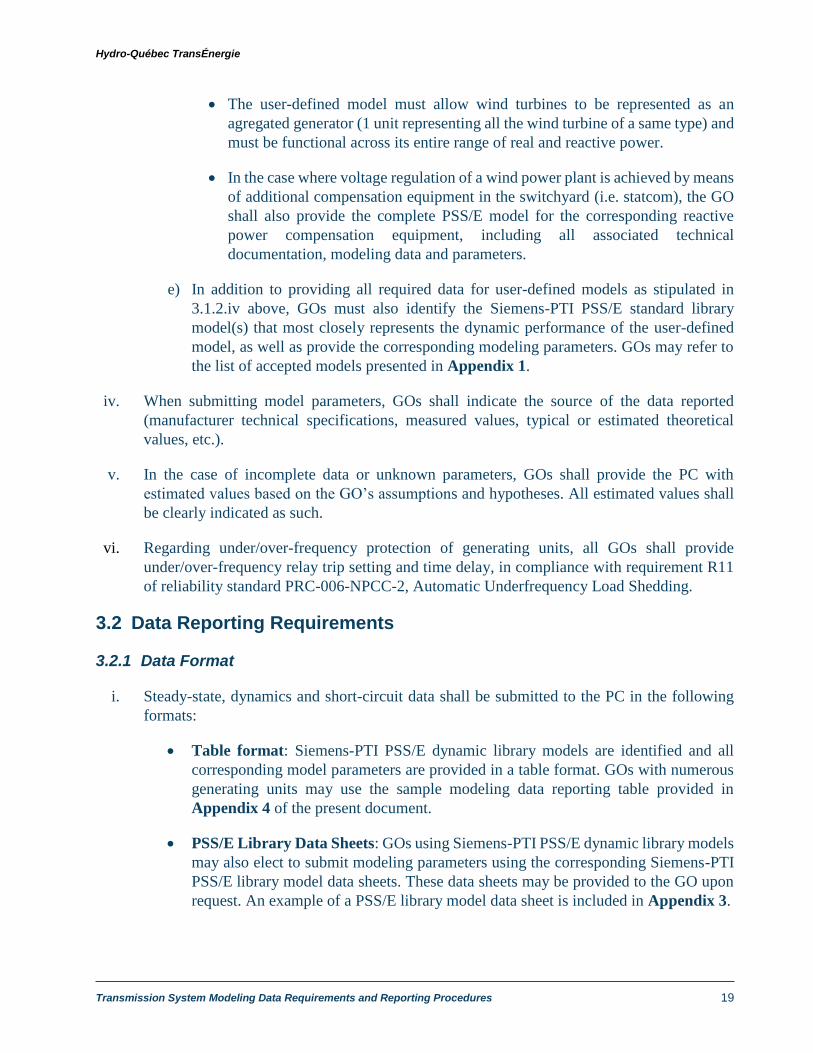
The user-defined model must allow wind turbines to be represented as an
agregated generator (1 unit representing all the wind turbine of a same type) and
must be functional across its entire range of real and reactive power.
In the case where voltage regulation of a wind power plant is achieved by means
of additional compensation equipment in the switchyard (i.e. statcom), the GO
shall also provide the complete PSS/E model for the corresponding reactive
power compensation equipment, including all associated technical
documentation, modeling data and parameters.
e) In addition to providing all required data for user-defined models as stipulated in
3.1.2.iv above, GOs must also identify the Siemens-PTI PSS/E standard library
model(s) that most closely represents the dynamic performance of the user-defined
model, as well as provide the corresponding modeling parameters. GOs may refer to
the list of accepted models presented in Appendix 1.
iv. When submitting model parameters, GOs shall indicate the source of the data reported
(manufacturer technical specifications, measured values, typical or estimated theoretical
values, etc.).
v. In the case of incomplete data or unknown parameters, GOs shall provide the PC with
estimated values based on the GO’s assumptions and hypotheses. All estimated values shall
be clearly indicated as such.
vi. Regarding under/over-frequency protection of generating units, all GOs shall provide
under/over-frequency relay trip setting and time delay, in compliance with requirement R11
of reliability standard PRC-006-NPCC-2, Automatic Underfrequency Load Shedding.
3.2 Data Reporting Requirements
3.2.1 Data Format
i. Steady-state, dynamics and short-circuit data shall be submitted to the PC in the following
formats:
Table format: Siemens-PTI PSS/E dynamic library models are identified and all
corresponding model parameters are provided in a table format. GOs with numerous
generating units may use the sample modeling data reporting table provided in
Appendix 4 of the present document.
PSS/E Library Data Sheets: GOs using Siemens-PTI PSS/E dynamic library models
may also elect to submit modeling parameters using the corresponding Siemens-PTI
PSS/E library model data sheets. These data sheets may be provided to the GO upon
request. An example of a PSS/E library model data sheet is included in Appendix 3.

Hydro-Québec TransÉnergie
Transmission System Modeling Data Requirements and Reporting Procedures 20
PSS/E SAV, DYR format: PSS/E dynamic library models are identified and all
corresponding steady-state and dynamics parameters are provided in SAV and DYR
files, respectively.
ii. In the case of user-defined models, GOs shall submit:
All associated model files required to run simulations in PSS/E (*.lib, *.obj, *.dll,
etc.). The PC may request the source code for certain user-defined models, which
must be submitted in the FLECS language of the current PSS/E revision, in C, or in
FORTRAN.
All corresponding user-defined model steady-state and dynamics parameters,
provided in SAV and DYR files, respectively.
All relevant technical documentation and characteristics of the user-defined model,
including compliance test results, block diagrams, values and names for all model
parameters and a list of all state variables.
Any IDEV or PYTHON programs necessary to set up dynamics simulation
parameters.
The Siemens-PTI PSS/E standard library model that most closely represents the
generating unit’s dynamics performance, along with all corresponding model
parameters.
iii. GOs shall provide generator outage information in an Excel table format.
3.2.2 Data Submission Procedure and Schedule
i. Data submission is to be performed annually according to the procedures and schedule
described in section 7.

Hydro-Québec TransÉnergie
Transmission System Modeling Data Requirements and Reporting Procedures 21
4. Transmission System Equipment Modeling
4.1 Modeling Data Requirements
All Transmission Owners within the Québec Interconnection shall provide the PC with valid
modeling data of all existing and future transmission system equipment, including:
AC transmission lines
DC transmission systems
Voltage and phase shifting transformers
Breakers
Shunt reactive compensation equipment (capacitors and reactors)
Series reactive compensation equipment
Static Var systems and synchronous condensers
Special protection systems (SPS)
The PC, in accordance with NERC’s MOD-032 standard, requires all TOs of existing facilities to
recertify system modeling data on an annual basis, either by resubmitting all required modeling data
or by certifying that data has not changed from the previous year’s data submission. In the case of
changes to modeling data, TOs must clearly identify all changes and submit all modified modeling
data in accordance with the requirements herein.
For future planned modifications, additions or upgrades of transmission system equipment, TOs must
submit preliminary modeling data to the PC and TPs during the planning phase of the project, during
which system impact studies are conducted. At this stage, estimated or typical modeling parameters
are acceptable.
TOs shall update the preliminary data provided to the PC during the project planning phase by
providing actual or measured modeling parameters based on equipment compliance testing results
conducted during the commissioning phase. The validation of modeling data is a prerequisite for
final TO acceptance of the transmission system facility project and must be completed within 6
months of initial commercial commissioning.
The following sections present the steady-state, dynamics and short-circuit data required to
effectively model transmission system equipment within the Québec Interconnection, defining the
type of data required and the units this data is to be reported in.

Hydro-Québec TransÉnergie
Transmission System Modeling Data Requirements and Reporting Procedures 22
4.1.1 Steady-State Data for Modeling Transmission Systems
i. Each TO shall provide steady-state modeling data of existing and future transmission
equipment according to the requirements set forth in the present document.
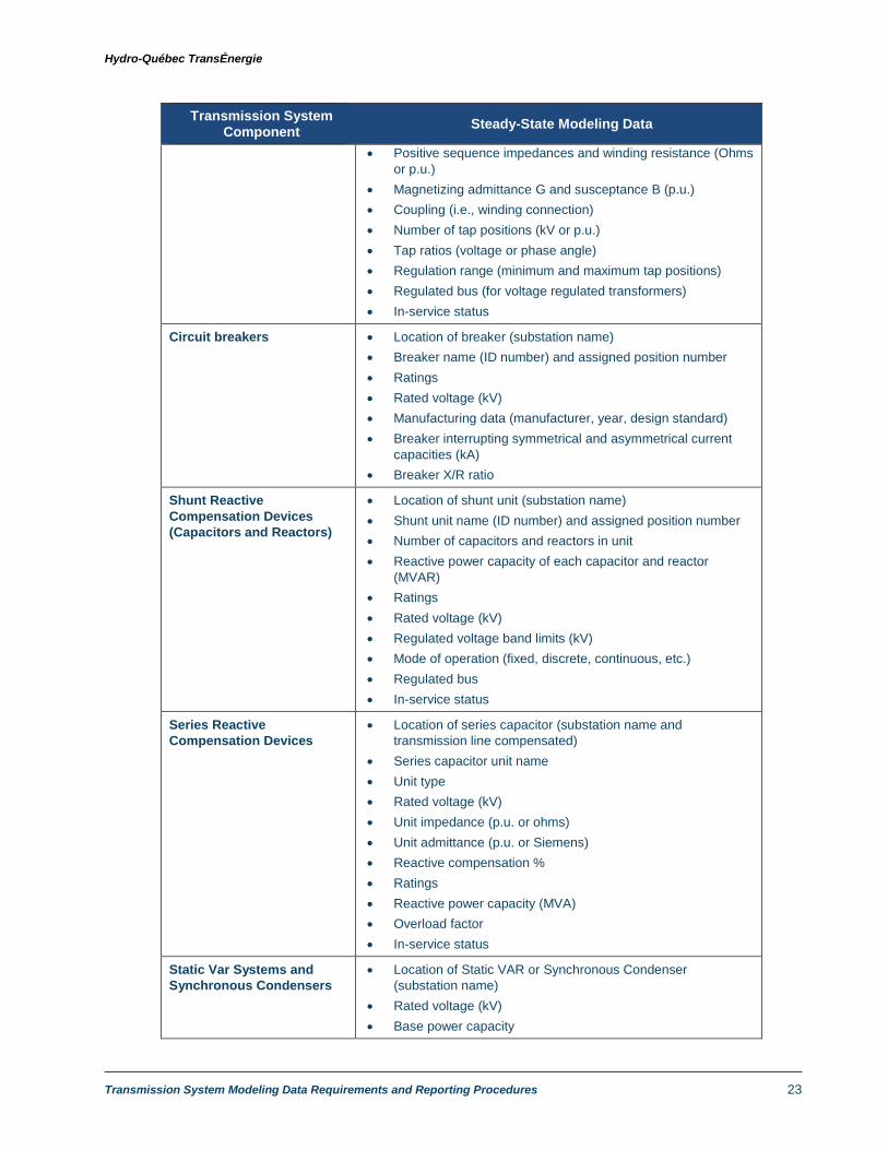
ii. The table below summarizes the main steady-state data requirements, as outlined in MOD-
032-1, A1- 1, 4-8.
Table 5 – Steady-state data requirements
for transmission equipment
Transmission System Component
Steady-State Modeling Data
Busbar assemblies Single-line diagram of the substation
Bar number name
Ratings
Rated voltage
Type of bus (substation bus bar, load or generator)
Area, zone and owner
Associated substation or line
AC Transmission Lines To and from buses or substations
Line length (km)
Impedance parameters (positive sequence), R and X (ohms
or p.u.)
Susceptance, B (Siemens or p.u.)
Ratings in normal and emergency conditions3
Thermal ratings at -20°C, 0°C and 30°C (MVA or A)
In-service status
DC Transmission Systems
(DC lines and converter
stations)
To and from buses or substations
DC Line length (km)
DC Line impedances and data (Voltage, Rcmp-Ohms,
Vcmode, CCC Itmax, Rdc-Ohms, Delti, Dcvmin, CCC Accel)
Rectifier and Inverter data (Primary base voltage, Bridges in
Series, Trans Ratio, CCC X, AC Tx From Bus, AC Tx To Bus,
Max Firing Angle, Commutating R and X, Max & Min Tap
Settings, Tap Step)
In-service status
Transformers (Voltage and
Phase Shifting)
Location of transformer (substation name)
Transformer name (ID number) and assigned position number
Nominal voltages of primary, secondary and tertiary windings
(kV)
Ratings in normal and emergency conditions4
Power ratings (MVA) with corresponding cooling method, at -
20°C, 0°C and 30°C
3 Ratings determined using FAC-008 methodology 4 Ratings determined using FAC-008 methodology
Hydro-Québec TransÉnergie
Transmission System Modeling Data Requirements and Reporting Procedures 23
Transmission System Component
Steady-State Modeling Data
Positive sequence impedances and winding resistance (Ohms
or p.u.)
Magnetizing admittance G and susceptance B (p.u.)
Coupling (i.e., winding connection)
Number of tap positions (kV or p.u.)
Tap ratios (voltage or phase angle)
Regulation range (minimum and maximum tap positions)
Regulated bus (for voltage regulated transformers)
In-service status
Circuit breakers Location of breaker (substation name)
Breaker name (ID number) and assigned position number
Ratings
Rated voltage (kV)
Manufacturing data (manufacturer, year, design standard)
Breaker interrupting symmetrical and asymmetrical current
capacities (kA)
Breaker X/R ratio
Shunt Reactive
Compensation Devices
(Capacitors and Reactors)
Location of shunt unit (substation name)
Shunt unit name (ID number) and assigned position number
Number of capacitors and reactors in unit
Reactive power capacity of each capacitor and reactor
(MVAR)
Ratings
Rated voltage (kV)
Regulated voltage band limits (kV)
Mode of operation (fixed, discrete, continuous, etc.)
Regulated bus
In-service status
Series Reactive
Compensation Devices
Location of series capacitor (substation name and
transmission line compensated)
Series capacitor unit name
Unit type
Rated voltage (kV)
Unit impedance (p.u. or ohms)
Unit admittance (p.u. or Siemens)
Reactive compensation %
Ratings
Reactive power capacity (MVA)
Overload factor
In-service status
Static Var Systems and
Synchronous Condensers
Location of Static VAR or Synchronous Condenser
(substation name)
Rated voltage (kV)
Base power capacity

Hydro-Québec TransÉnergie
Transmission System Modeling Data Requirements and Reporting Procedures 24
Transmission System Component
Steady-State Modeling Data
Ratings
Reactive power limits (MVAR)
Regulated bus
Voltage set point (p.u. or kV)
In-service status
iii. Attribution of busbar numbers is done by the PC.
iv. For all future additions or upgrades where HQT is TO, steady-state modeling data shall reflect
technical data specified in the Design Specifications Document (cahier des charges).
v. Regarding “in-service status,” a 10-year forecast of scheduled outages of duration greater
than 6 months shall be provided by TOs on a yearly basis. Outage information shall consist
of:
Start and end dates of planned outage
Transmission equipment scheduled to be out of service
Voltage level
Location (substation name, zone, etc.)
Description of project or maintenance causing outage
4.1.2 Transmission System Equipment Dynamics and Short-Circuit Data Reporting
Requirements
i. Each TO shall provide short-circuit and dynamics modeling data of existing and future
transmission equipment according to the requirements set forth in the present document.
ii. The table below summarizes the main short-circuit and dynamics modeling data
requirements, as outlined in MOD-032-1, A1.
Table 7 – Requirements for steady-state, dynamic and short-circuit modeling data
for transmission equipment
Transmission System Component
Dynamics and short-circuit modeling data
AC Transmission Lines Positive, negative and zero sequence impedance parameters,
R and X (ohms or p.u.)
Zero sequence susceptance, B (Siemens or p.u.)
Mutual impedance data
DC Transmission Systems
(DC lines and converter
stations)
DC line dynamics model and associated parameters
DC converter dynamics model and associated parameters

Hydro-Québec TransÉnergie
Transmission System Modeling Data Requirements and Reporting Procedures 25
Transformers (Voltage and
Phase Shifting)
Winding connection
Positive, negative and zero sequence impedance parameters,
R and X (ohms or p.u.)
Positive, negative and zero sequence grounding impedances,
RG and XG (ohms or p.u.)
Shunt Reactive
Compensation Devices
(Capacitors and Reactors)
Zero sequence shunt admittances, G and B (p.u.)
Series Reactive
Compensation Devices
Zero sequence impedances, R and X (p.u. or ohms)
Zero sequence admittance, B (p.u. or Siemens)
Unit admittance (p.u. or Siemens)
Static Var Systems and
Synchronous Condensers
and others Flexible
Alternative Current
Transmission System
(FACTS)
Positive sequence machine impedances, R1 and X1 (p.u.)
Negative sequence machine impedances, R2 and X2 (p.u.)
Zero sequence machine impedances, R0 and X0 (p.u.)
Static Var System equipment dynamics model and associated
parameters
Synchronous Condenser dynamics model and associated
parameters
Automated system controls SPS dynamics model and associated parameters
iii. All dynamics models submitted to the PC must be compatible with the current version5 of
Siemens-PTI’s PSS/E software, which is used by the PC and TPs for dynamics system
studies.
The use of Siemens-PTI PSS/E standard dynamics models is preferred when they can
accurately represent the dynamic performance of the device being modeled.
Models accepted by the PC are listed in Appendix 1 of the present document.
iv. User-defined models
a) If a compatible standard IEEE or PSS/E dynamics model is unavailable, user-defined
or “black-box” models may be used. A user-defined model is any model that is not a
standard Siemens-PTI PSS/E library model but has been accepted by the PC after
being successfully tested for compatibility.
b) User-defined models submitted to the PC shall fulfill the following requirements:
User-defined models must be able to work with a time-step exceeding 4 ms (1/4
cycle).
5 PSS/E version 34.8

Hydro-Québec TransÉnergie
Transmission System Modeling Data Requirements and Reporting Procedures 26
User-defined models must be accompanied by a user manual providing all relevant
technical documentation and characteristics of the model, including block
diagrams, values and names for all model parameters and a list of all state variables.
TOs must also provide compliance test results demonstrating that the model
accurately represents the dynamic performance of the device being modeled. TOs
must ensure that model compliance testing is performed every 10 years.
c) TOs are responsible for validating and maintaining all dynamics models, ensuring that
models submitted to the PC are compatible and fully functional in the current version
of PSS/E, allowing for error-free initialization. In the event of PSS/E version updates
(PC migrates to a newer version of the PSS/E software), TOs shall provide all
necessary model updates, ensuring all models are compatible with the new version of
PSS/E.
d) In addition to providing all required data for user-defined models as stipulated in
4.1.2.iv-vi, TOs must also identify the Siemens-PTI PSS/E standard library model(s)
that most closely represents the dynamic performance of the user-defined model, as
well as provide the corresponding modeling parameters. GOs may refer to the list of
accepted models presented in Appendix 2.
v. In the case of incomplete data or unknown parameters, TOs shall provide the PC with
estimated values based on the TO’s assumptions and hypotheses. All estimated values shall
be clearly indicated as such.
vi. For all future additions or upgrades where HQT is TO, short-circuit modeling data shall
reflect technical data specified in the Design Specifications Document (cahier des charges).
4.1.3 Additional modeling data needed to calculate DC currents during geomagnetic
storms
i. Every TO must provide, for the transmission facilities involved, the modeling data needed to
calculate DC currents during geomagnetic storms, and perform the analyses required by
standard TPL-007.
ii. The table below summarizes the main modeling data requirements.
Table 8 – Modeling data needed to calculate DC currents during geomagnetic storms
Transmission System Component
Modeling Data
Transmission substation Substation grid resistance (Ohms)
Coordinates of the substation:
latitude (positive for north and negative for south)
longitude (positive for east and negative for west)
Transmission lines DC resistance (Ohms/phase)

Hydro-Québec TransÉnergie
Transmission System Modeling Data Requirements and Reporting Procedures 27
Coordinates of the line tap
latitude (positive for north and negative for south)
longitude (positive for east and negative for west)
Number of overhead ground and counterpoise wires
Transformers (Voltage and
Phase Shifting)
(if one of the winding voltages
is > 200 kV and one of the
transformer connections is
grounded)
DC resistance (Ohms/phase) for each winding
Core design
o Three phase shell
o Single core
o 3-phase 3-legged
o 3-phase 5-legged
etc.
Coefficient of reactive power losses as a function of DC
current in the transformer (K factor)
Ground resistance (Ohms)
Presence of DC current blocking mechanism on the
neutral
Shunt reactor DC resistance of winding (Ohms/phase)
Ground resistance (Ohms)
4.2 Data Reporting Requirements
4.2.1 Data Format
i. Steady-state, dynamics and short-circuit data shall be submitted to the PC in the following
formats:
Table format: Siemens-PTI PSS/E dynamic library models are identified and all
corresponding model parameters are provided in a table format.
PSS/E SAV, DYR format: PSS/E dynamic library models are identified and all
corresponding steady-state and dynamics parameters are provided in RAW and DYR
files, respectively.
ii. TOs shall also submit a single-line diagram, illustrating the planned or commissioned
transmission system additions and/or modifications.
iii. In the case of user-defined models, TOs shall submit:
All associated model files required to run simulations in PSS/E (*.lib, *.obj, *.dll,
etc.). The PC may request the source code for certain user-defined models, which
must be submitted in the FLECS language of the current PSS/E revision, in C, or in
FORTRAN.
All corresponding user-defined model steady-state and dynamics parameters,
provided in SAV and DYR files, respectively.

Hydro-Québec TransÉnergie
Transmission System Modeling Data Requirements and Reporting Procedures 28
All relevant technical documentation and characteristics of the user-defined model,
including compliance test results, block diagrams, values and names for all model
parameters and a list of all state variables.
Any IDEV or PYTHON programs necessary to set up dynamics simulation
parameters.
The Siemens-PTI PSS/E standard library model that most closely represents the
generating unit’s dynamics performance, along with all corresponding model
parameters.
iv. The TO shall provide transmission system equipment outage information in the form of a
report or a simplified Excel table.
4.2.2 Data Submission Procedure and Schedule
i. Data submission is to be performed annually according to the procedures and schedule
described in section 7.

Hydro-Québec TransÉnergie
Transmission System Modeling Data Requirements and Reporting Procedures 29
5. Modeling of Demand
5.1 Modeling Data Requirements
The main Load Serving Entity (LSE), in this case Hydro-Québec Distribution (HQD), is responsible
for preparing and submitting demand data to the Planning Coordinator (PC) for the entire Québec
Interconnection.
The following sections present the steady-state, dynamics and short-circuit data required to
effectively model demand within the interconnected transmission system, defining the type of data
required and the units this data is to be reported in.
5.1.1 Steady-State Data Requirements for Demand Modeling
The table below summarizes the steady-state data requirements for loads at satellite
substations (< 44 kV) and loads for customer facilities (municipal systems, large industrial
plants, pulp and paper mills, aluminum smelters, refineries, mining facilities, etc.), directly
connected to the high voltage transmission system (44 kV to 324 kV).
Table 9 – Steady-state data requirements
Steady-State Data Requirements for Demand Modeling
Satellite substation loads < 44 KV (15-year forecast)
Customer facility loads modeled at higher than 44 KV (10 year forecast)
Substation location code
Substation name
Active power (MW)
Reactive power (MVAR)
Load apparent power (MVA)
Rated power (MVA) and voltage
(kV) of low-voltage side reactive
compensation equipment
Location code
Substation name
Active power (MW)
Total load apparent power
(MVA)
Load in-service status
i. Load data submitted to the PC shall reflect the following annually prepared demand forecasts:
A 15-year demand forecast by substation, aggregated by secondary voltage level for
all satellite substations serving the Hydro-Québec distribution system load with a
secondary busbar voltage < 44 kV
A 10-year demand forecast by substation at the high-voltage side for industrial
customers (e.g., municipal distribution systems, large industrial plants, etc.)
connected directly to the high voltage transmission system (44 to 324 kV)

Hydro-Québec TransÉnergie
Transmission System Modeling Data Requirements and Reporting Procedures 30
A 10-year Interconnection-wide aggregated demand forecast for the entire
interconnection.
ii. Each demand forecast shall provide load data for the following types of load levels:
Winter peak in normal weather conditions
Summer peak6
Summer light load7
iii. HQD must also provide historical peak load data, standardized over five years for all satellite
substations serving the system, with secondary bus voltage of under 44 kV.
iv. In the case of new customer facilities connected directly to the high voltage transmission
system, the submission of more detailed modeling data is required prior to the commissioning
of new customer facilities, as stipulated in the “Technical Requirements for Customer
Facilities Connected to the Hydro-Québec Transmission System” document. The most
updated version of the document is readily available on HQT’s website at:
http://www.hydroquebec.com/transenergie/fr/commerce/pdf/ex_inst_client.pdf.
v. Existing customer facilities must also provide load modeling data according to these same
technical requirements upon request from the PC or in the event of any modifications to
customer facilities.
5.1.2 Short-Circuit and Dynamics Data Requirements for Demand Modeling
i. Short-circuit and dynamics data is normally required for customer facilities equipped with
large motors that can impact the transmission system’s transient and dynamic performance.
This information is normally provided by customer facilities prior to commissioning and
connection to the transmission system or in the event of modifications to existing customer
facilities.
ii. Customer facilities, with the collaboration of HQD, shall provide short-circuit and dynamics
data according to the requirements set forth in Appendix 1 of HQT’s “Technical
Requirements for Customer Facilities Connected to the Hydro-Québec Transmission System”
document. The most updated version of the document is readily available on HQT’s website
at:
http://www.hydroquebec.com/transenergie/fr/commerce/pdf/ex_inst_client.pdf.
6 The summer peak load forecast is to be submitted on demand only. 7 The summer light load forecast is to be submitted by source substation on demand only. The planning coordinator
will provide the correspondence list for source and satellite substations, if required.

Hydro-Québec TransÉnergie
Transmission System Modeling Data Requirements and Reporting Procedures 31
iii. Customer facilities must also indicate the source of the data submitted (manufacturer
technical specifications, measured values, typical or estimated theoretical values, etc.).
iv. In the case of incomplete data or unknown parameters, HQD/Customer facilities are
responsible for providing theoretical or estimated values.
5.2 Data Reporting Requirements
5.2.1 Data Format
i. Steady-state load data submitted to the PC shall be presented in an Excel table or any other
format upon agreement with the PC.
ii. Short-circuit and dynamic load data shall be submitted to the PC using the modeling data
template provided in Appendix A of the “Technical Requirements for Customer Facilities
Connected to the Hydro-Québec Transmission System” document. All fields of the said
document must be completed in order to be considered as a valid data submission. Other
accepted data submission formats for short-circuit and dynamic load data are the following:
Excel Table listing model parameters
PSS/E SAV and DYR files, with all corresponding PSS/E dynamic model files.
5.2.2 Data Submission Procedure and Schedule
i. Data submission is to be performed annually according to the procedures and schedule
described in section 7.

Hydro-Québec TransÉnergie
Transmission System Modeling Data Requirements and Reporting Procedures 32
6. Complementary Power System Information
In addition to steady-state and dynamics models, transmission system modeling requires quantitative
information about the power system to establish generation dispatch and interconnection wheeling
levels. This additional information consists of resource planning data and interchange transfer
quantities to neighbouring Areas.
The following sections present the data required to effectively integrate resource planning and
interchange data into power flow and dynamics cases, defining the type of data required and the units
this data is to be reported in.
6.1 Resource Plan Data
6.1.1 Resource Planning Data Requirements
i. The Resource Planner (RP), in this case Hydro-Québec Distribution (HQD), shall provide the
PC with data regarding all long term generation purchasing agreements between GOs and
LSEs, determining the generating resources available to fulfill demand requirements.
ii. The Resource Planner (RP) shall provide the interruptible load planning hypothesis and
details about any Direct Control Load Management (DCLM) programs.
6.1.2 Data Format
i. Resource data shall be reported in an Excel table format in a mutually agreed format between
the RP and the PC.
6.1.3 Data Submission Procedure and Schedule
i. Data submission is to be performed annually according to the procedures and schedule
described in section 7.
6.2 Interchange Schedule
An Interchange schedule is a list of scheduled power transfer quantities exchanged between the
Québec Interconnection and its neighbouring Area systems (i.e. New England, New York, Ontario,
and New Brunswick). These transactions and transmission reservations reflect firm export/import or
point-to-point transmission agreements, as per HQT’s Open Access Transmission Tariff (OATT).
This information is published on the OATI webOASIS application and provided to the PC by the
Transmission Service Provider (TSP).

Hydro-Québec TransÉnergie
Transmission System Modeling Data Requirements and Reporting Procedures 33
6.2.1 Interchange Data Requirements
i. The TSP shall collect and provide the required interchange data regarding firm long term
transmission reservations (1 year or more) between transmission systems within the Québec
Interconnection as well as with transmission systems of neighbouring NPCC Areas. This
information must be reflective of the most updated transaction information available on OATI
webOASIS.
ii. Interchange data shall include:
Transmission service customer name
OASIS reference number
Source and destination substations
Name of interconnection path
Power flow (MW)
Transaction frequency (yearly, monthly, etc.)
Transmission service type
Start and end date of transmission service contract
6.2.2 Data Format
i. Interchange data shall be reported in an Excel table format or any other format upon
agreement with the PC.
6.2.3 Data Submission Procedure and Schedule
i. Data submission is to be performed annually according to the procedures and schedule
described in Section 7.

Hydro-Québec TransÉnergie
Transmission System Modeling Data Requirements and Reporting Procedures 34
7. Data Submission Procedure and Schedule
7.1 Data Submission Procedure
i. All communications regarding modeling data reporting must be e-mailed to:
ii. Data submission is to be performed electronically or by email, preferably using a secure file
transfer server such as Hydro-Québec’s secure FTP server, available to HQ entities at
https://ftps.hydro.qc.ca/ and external customers at https://ftps.hydroquebec.com/.
iii. Periodicity of declaration
Data shall be submitted annually according the schedule presented in the present section. The
entity shall indicate clearly the modifications from the previous declaration or, where
applicable, indicate that the data hasn’t changed.
7.2 Data Submission Schedule
All concerned entities responsible for providing modeling data shall submit data annually according
to the following schedule:
Table 10 – Modeling Data Submission Schedule
Modeling Data Description of Deliverables
Functional Entity Responsible
Date of declaration
Aggregate Demand
Data
Steady-state winter peak load forecast Distribution Provider October 1
Steady-state summer peak and light load
forecasts
Distribution Provider October 1
Steady-state demand forecast for
industrial customer facilities
Distribution Provider October 1
Total system load forecast Resource Planner October 1
Generation Data Steady-state, dynamics and short-circuit
modeling data for existing equipment
Generator Owners February 1
Steady-state, dynamics and short-circuit
modeling data for new future planned
projects
Generator Owners February 1
Generator facilities outage schedule Generator Owners February 1
Transmission
System Equipment
Data
Recertification of steady-state, dynamics
and short-circuit modeling data for
existing equipment
Transmission Owners February 1

Hydro-Québec TransÉnergie
Transmission System Modeling Data Requirements and Reporting Procedures 35
Modeling Data Description of Deliverables
Functional Entity Responsible
Date of declaration
Steady-state, dynamics and short-circuit
modeling data for new future planned
projects
Transmission Owners
Transmission Planners
February 1
Transmission system equipment outage
schedule
Reliability Coordinator February 1
Complimentary
Power System
Information
Resource plan data Resource Planner October 1
Interchange Data Requirements Transmission Service
Provider
February 1
7.3 Non-Compliances
For entities registered with the Régie, failure to submit required modeling data by the prescribed
submission schedule and in the requested format may be in violation of the requirements established
in NERC’s MOD-032 standard.
For more information regarding compliance violations, functional entities may refer to pages 6-12 of
the MOD-032-1 standard document, available on the Régie’s website at:
http://www.regie-energie.qc.ca/audiences/NormesFiabiliteTransportElectricite/Normes/MOD-032-
1-fr-2017-01-31.pdf

Hydro-Québec TransÉnergie
Transmission System Modeling Data Requirements and Reporting Procedures 36
APPENDIX 1 – List of Accepted Dynamics Models
See excel document “Appendix 1” (http://www.hydroquebec.com/transenergie/en/modeling.html)
The Planning Coordinator currently uses PSS/E version 34.8.

Direction – Planification
Hydro-Québec TransÉnergie
A division of Hydro-Québec