Embed Size (px)
Citation preview

Transmission Lines As Impedance Transformers
Bill Leonard N0CU
285 TechConnect Radio Club
2017 TechFest

• Review impedance basics
• Review Smith chart basics
• Demonstrate how antenna analyzers display impedance data
• Demonstrate some important transmission line characteristics
Topics
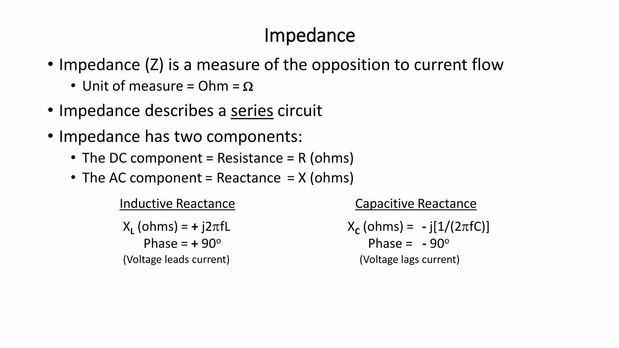
• Impedance (Z) is a measure of the opposition to current flow• Unit of measure = Ohm = W
• Impedance describes a series circuit
• Impedance has two components:• The DC component = Resistance = R (ohms)
• The AC component = Reactance = X (ohms)
Inductive Reactance Capacitive Reactance
XL (ohms) = + j2pfL XC (ohms) = - j[1/(2pfC)]Phase = + 90o Phase = - 90o
(Voltage leads current) (Voltage lags current)
Impedance

• Impedance can be expressed in two ways:1. Resistance and reactance => Z = R + jX (Complex Number)
2. Magnitude and phase => Z = Z q
• Magnitude of Z (ohms) = Z = R2+X2
• Phase of impedance (degrees) = q = arctan(X/R)
Impedance – cont’d
RZ
X
q

Impedance of a Series Circuit
XL
R
XC X
R
X = [XL – XC]
1. Z = R + j X = R + j(XL – XC) = R + j[(2pfL – 1/(2pfC)]2. Z = Z and q
Z =>
L
R
C XL
R
XC
=>
Specify afrequency
=>Step 1
Step 2

• Z is defined only for a series circuit• Must convert a parallel circuit to a series circuit
• Frequency must be known to do the conversion
• Both component values change when converted
Impedance of a Parallel Circuit
RPXP
XS
RS
RS =RP x XP
2
RP2 + XP
2
XS =RP
2 x XP
RP2 + XP
2
Z = RS + j XS
Z = RP + jXP
= ?

Example 1: Impedance at 2 MHz
-j50W
50W
Equivalent Series Circuit
Note: Two different circuits have the same impedance at 2 MHz:Z = 50W - j50W = 70.7W @ -45o
100W-j100W100W796 pFStep 1
Physical Circuit
=>
100W-j100W => 1592 pFRP
XPStep 2
XP
RP

• What an MFJ-259B measured at 2 MHz:
Example 1: Impedance at 2 MHz - cont’d
Rs=Xs= Z =
Phase = SWR =
Calculated50 W-50 W70 W
-45O
2.6
Measured56 W48 W74 W40O
2.4
100W796 pFZ =>
Physical Circuit
“Impedance” Meter = 70 70 => Z
Note: The MFJ-259B does not display RP, XP, or the sign of a reactance

Transmission Lines Are Lowpass Filters
• “Lumped element” circuit approximation for lossless transmission line:
• ZO is called the “Surge Impedance” or “Characteristic Impedance” of the line• When ZLOAD = ZO
• The line is “Matched”
• The input impedance of a transmission line equals ZO and is independent of length
• ZO ~ L/C
• Example: Belden RG-58/U (9201)
Zo = 52W
C = 27 pF/ft
L = 94 nH/ft
VP = 0.66
~
L
C ….L
Zo =>

When ZLOAD = ZO
RLOAD = 100 ohm
Input impedance of a 50 ohm line when the SWR = 2.0:
RLOAD = 25 ohm
ZIN =>
ZIN =>

• What is ZIN at 32 MHz ?
Example 2
61 inches RG-58 C/U
122 inches RG-58 C/U
ZIN = 50W
ZIN = 50W
50W
50W
• What is ZIN at 32 MHz ?
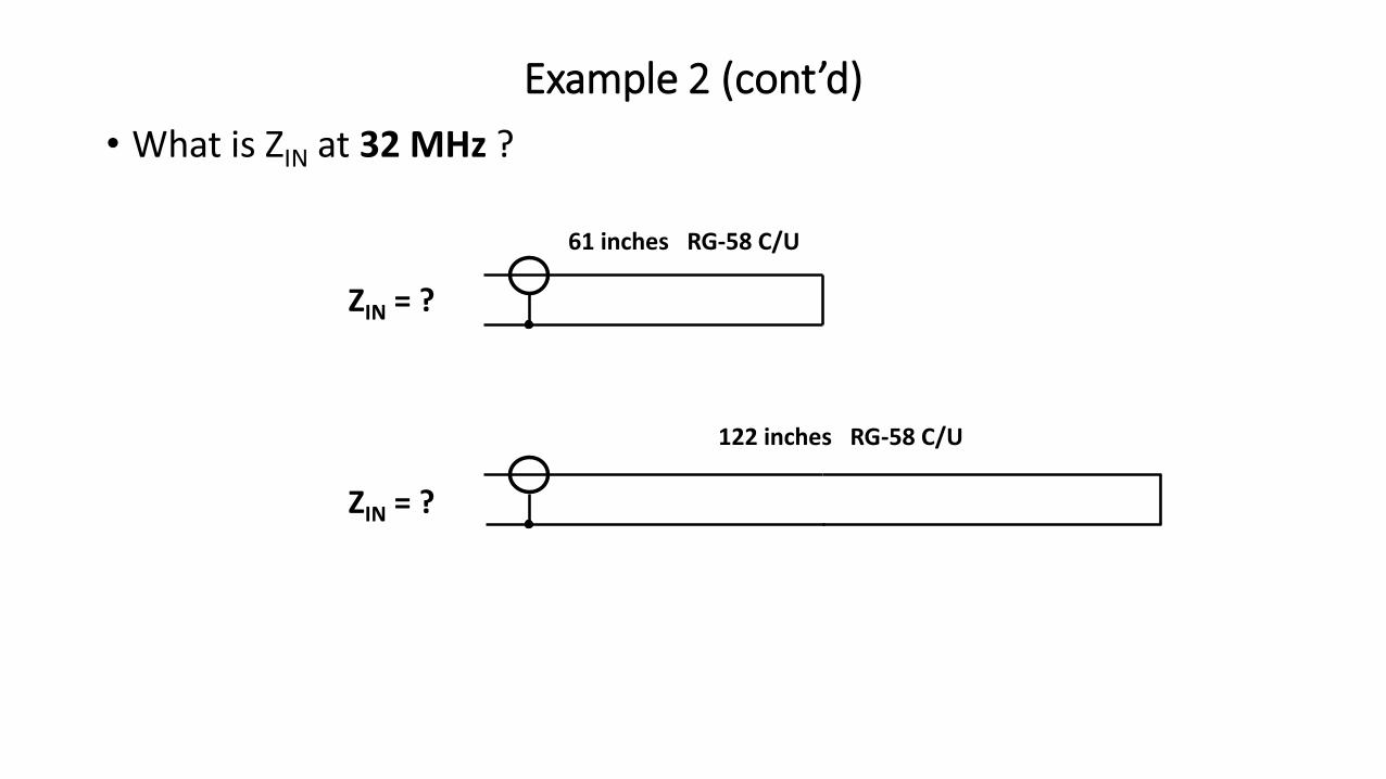
Example 2 (cont’d)
61 inches RG-58 C/U
122 inches RG-58 C/U
ZIN = ?
ZIN = ?

• What is ZIN at 32 MHz ?
Example 2 (cont’d)
ZIN = OPEN
ZIN = SHORT
61 inches RG-58 C/U
122 inches RG-58 C/U

• What is ZIN at 32 MHz ?
Example 2 (cont’d)
ZIN = SHORT
ZIN = OPEN
61 inches RG-58 C/U
122 inches RG-58 C/U

Example 2 (cont’d)
• The electrical lengths at 32 MHz are:• 61 inches = ¼ wavelength
• 122 inches = ½ wavelength
• Electrical length = VP x physical length• “VP” = velocity of propagation
• When ZLoad = ZO:• ZIN = ZO = ZLoad (for any length of line)
• When ZLoad = ZO:• Transmission lines become impedance transformers
• When length = nodd x ¼ wavelength, transmission lines invert the load impedance• “Invert” => high goes to low and low goes to high
• Quarter wave transformer: ZIN = (ZO )2/ ZLOAD
• When length = n x ½ wavelength, transmission lines replicate the load impedance
Electrical length = physical length

Quiz: High SWR
ZIN = Short @ 7 MHz Ant
Is the antenna shorted?
? feet transmission line
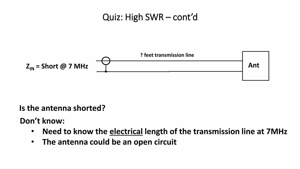
Quiz: High SWR – cont’d
Don’t know: • Need to know the electrical length of the transmission line at 7MHz• The antenna could be an open circuit
? feet transmission line
AntZIN = Short @ 7 MHz
Is the antenna shorted?
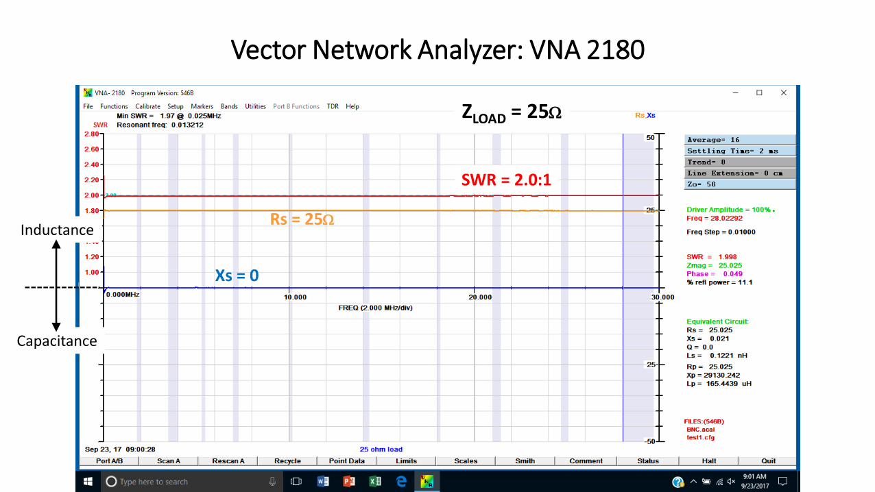
Vector Network Analyzer: VNA 2180
Rs = 25W
Xs = 0
SWR = 2.0:1
Inductance
Capacitance
ZLOAD = 25W
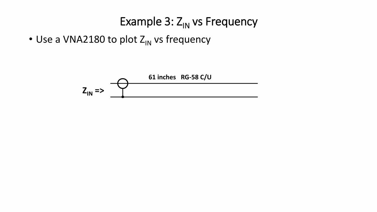
• Use a VNA2180 to plot ZIN vs frequency
Example 3: ZIN vs Frequency
ZIN =>
61 inches RG-58 C/U

Rs = series resistance
Example 3: ZIN vs Frequency (cont’d)
Xs = series reactance
Inductance
Capacitance
Repeats every ½ wavelength
61 inches RG-58 C/UZLOAD = OPEN

VNA 2180 With 25W Load
ZMAG = 25W
ZPhase = 0
Inductance
Capacitance

Example 3: Plot ZIN vs Frequency (cont’d)
ZMAG = Impedance Magnitude
Note: Line loss reduces SWR & ZMAG
61 inches RG-58 C/UZLOAD = OPEN

Example 3: Plot ZIN vs Frequency (cont’d)
Impedance Phase+90o
-90o
SeriesResonance
ParallelResonance
Inductance
Capacitance
61 inches RG-58 C/UZLOAD = OPEN

Example 3: Plot ZIN vs Frequency (cont’d)
61 inches RG-58 C/UZLOAD = OPEN
¼ wavelength
Impedance Phase
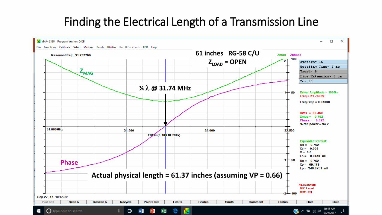
Finding the Electrical Length of a Transmission Line
¼ l @ 31.74 MHz
61 inches RG-58 C/UZLOAD = OPEN
Actual physical length = 61.37 inches (assuming VP = 0.66)
ZMAG
Phase

Finding the Input Impedance of a Transmission Line
ZLZO

Hyperbolic Tangent
ComplexNumbers
Why Was The Smith Chart Developed?
Impedance LookingInto A Transmission
Line

Smith Chart

Resistance
Simplified Smith Chart
Z = 50 – j50 ohms

System Impedance Normalized to 1
Normalized Smith Chart
Z= 1 – j1 ohms
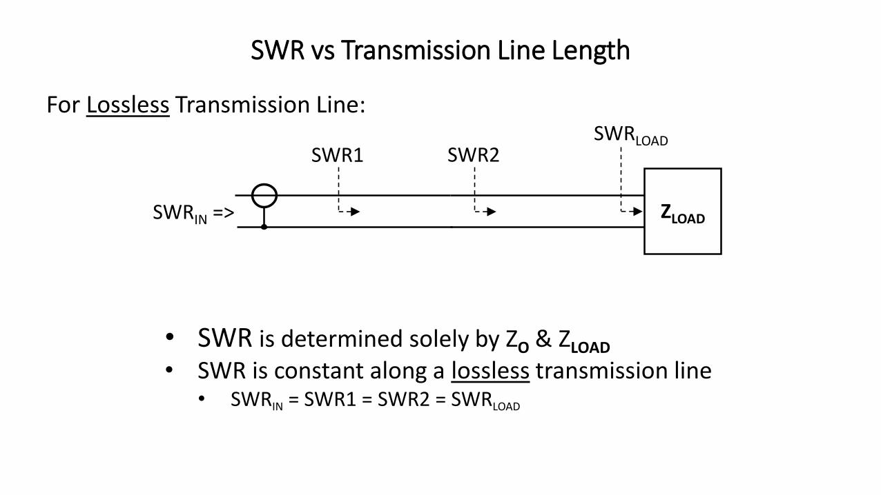
SWR vs Transmission Line Length
SWRIN =>
For Lossless Transmission Line:
• SWR is determined solely by ZO & ZLOAD
• SWR is constant along a lossless transmission line• SWRIN = SWR1 = SWR2 = SWRLOAD
ZLOAD
SWR1 SWR2SWRLOAD
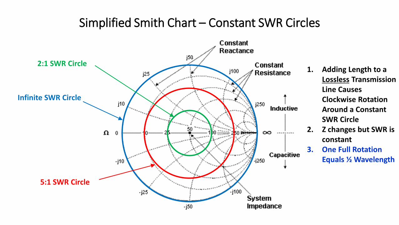
Simplified Smith Chart – Constant SWR Circles
Infinite SWR Circle
5:1 SWR Circle
2:1 SWR Circle1. Adding Length to a
Lossless Transmission Line Causes Clockwise Rotation Around a Constant SWR Circle
2. Z changes but SWR is constant
3. One Full Rotation Equals ½ Wavelength

Problem: Antenna Tuner Can’t Find A Match
• Many built-in antenna tuners can only match up to a 3:1 SWR• External tuners have much better range than built-in tuners
• It is easier for most antenna tuners to match a high impedance• Ex: MFJ-993B spec’d matching range is 6 – 1600W
• SWR:1600W => 32:1
6W => 8:1
• Many antenna tuners become very lossy at very low impedances• Obtaining a match is only part of the solution
• Example: Palstar AT-Auto• Loss matching 6.25 ohms on 160M is 42%! (QST Aug 2006)
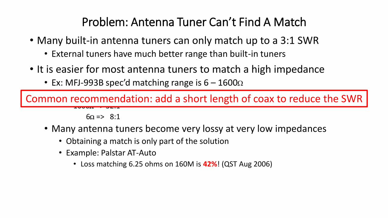
Common recommendation: add a short length of coax to reduce the SWR

Example 4: Antenna Matching Problem
• Problem: Antenna Tuner Can’t Find A Match At 14.0 MHz:
Zo = 50W
ZIN = 10W + j1.3W
SWR = 5.0:1ZL = 250W=>
Zo = 50WZIN = 50W
SWR = 1.0:1ZL = 250W=> Antenna
Tuner
=>

Example 4: Antenna Matching Problem (cont’d)
Z = 10+j1.3W
SWR = 5.02:1

Example 4: Antenna Matching Problem (cont’d)
Z = 10+j1.3W
SWR = 5.02:1

Example 4: Antenna Matching Problem (cont’d)
Z = 55+j92W
SWR = 4.9:1Additional 8.2 ft of RG-8A Cable
• Match should be possible due to higher impedance• SWR didn’t change!• The loss in the tuner should be lower
Example 4: Antenna Matching Problem (cont’d)
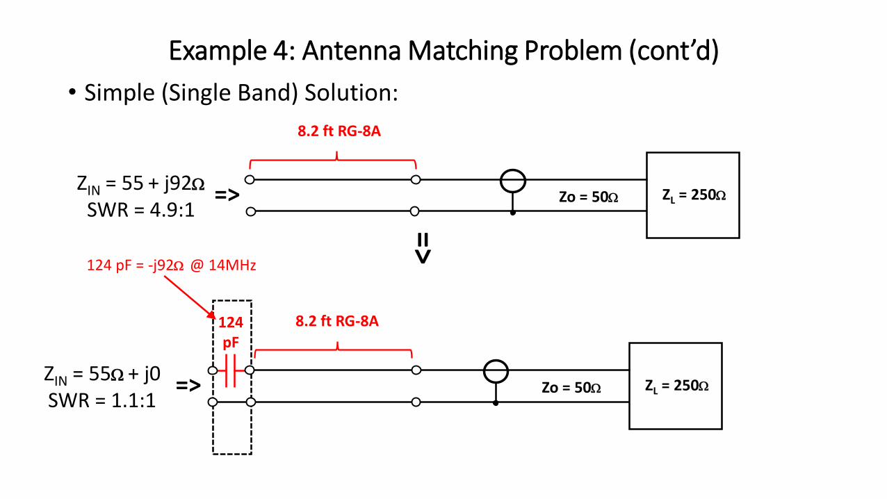
• Simple (Single Band) Solution:
Zo = 50WZIN = 55W + j0SWR = 1.1:1
ZL = 250W=>
=>
124pF
124 pF = -j92W @ 14MHz
Zo = 50WZIN = 55 + j92W
SWR = 4.9:1ZL = 250W=>
8.2 ft RG-8A
8.2 ft RG-8A

ARRL Transmission Line for Windows (TLW)
• Free software with ARRL Antenna Book

Example 5: Antenna Tuning
• Should an antenna be tuned to resonance, or for lowest SWR?
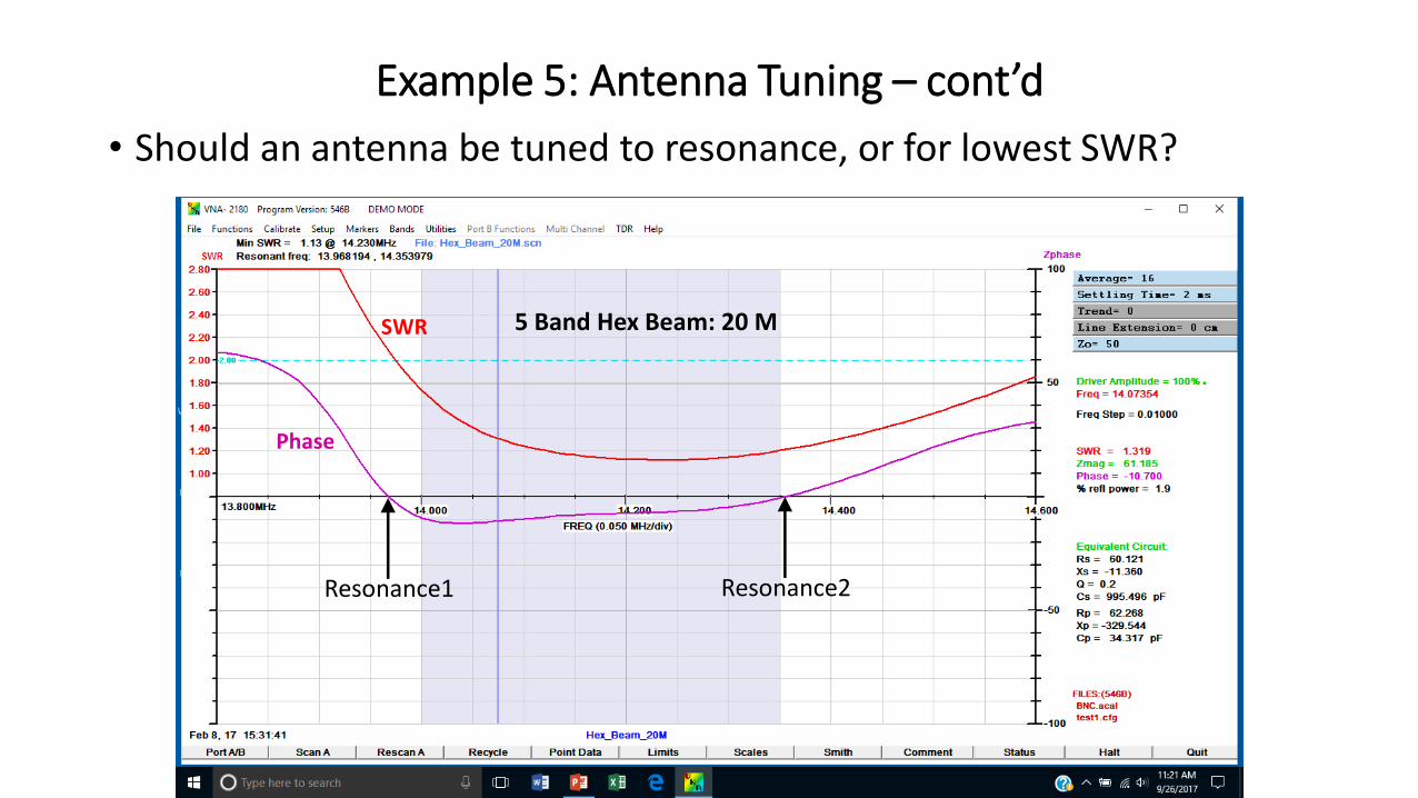
Example 5: Antenna Tuning – cont’d
• Should an antenna be tuned to resonance, or for lowest SWR?
5 Band Hex Beam: 20 MSWR
Phase
Resonance1 Resonance2

Example 5: Antenna Tuning – cont’d
40 M Dipole
SWR
Phase

Example 5: Antenna Tuning – cont’d
40 M Dipole 40 M Dipole at input to transmission line
SWR
Phase
SWR
Phase
Is the antenna no longer resonant?

Example 5: Antenna Tuning – cont’d
40 M Dipole at input to transmission line40 M Dipole

Example 5: Antenna Tuning – cont’d
40 M Dipole at input to transmission line40 M Dipole
• The antenna is still resonant• The antenna “System” is not resonant?

Example 5: Antenna Tuning – cont’d
SWR
• Tuning for minimum SWR is usually the best approach• Resonance:
• Is not required for good antenna performance• May not occur at the same frequency as minimum SWR
• SWR affects transmitter output, not resonance
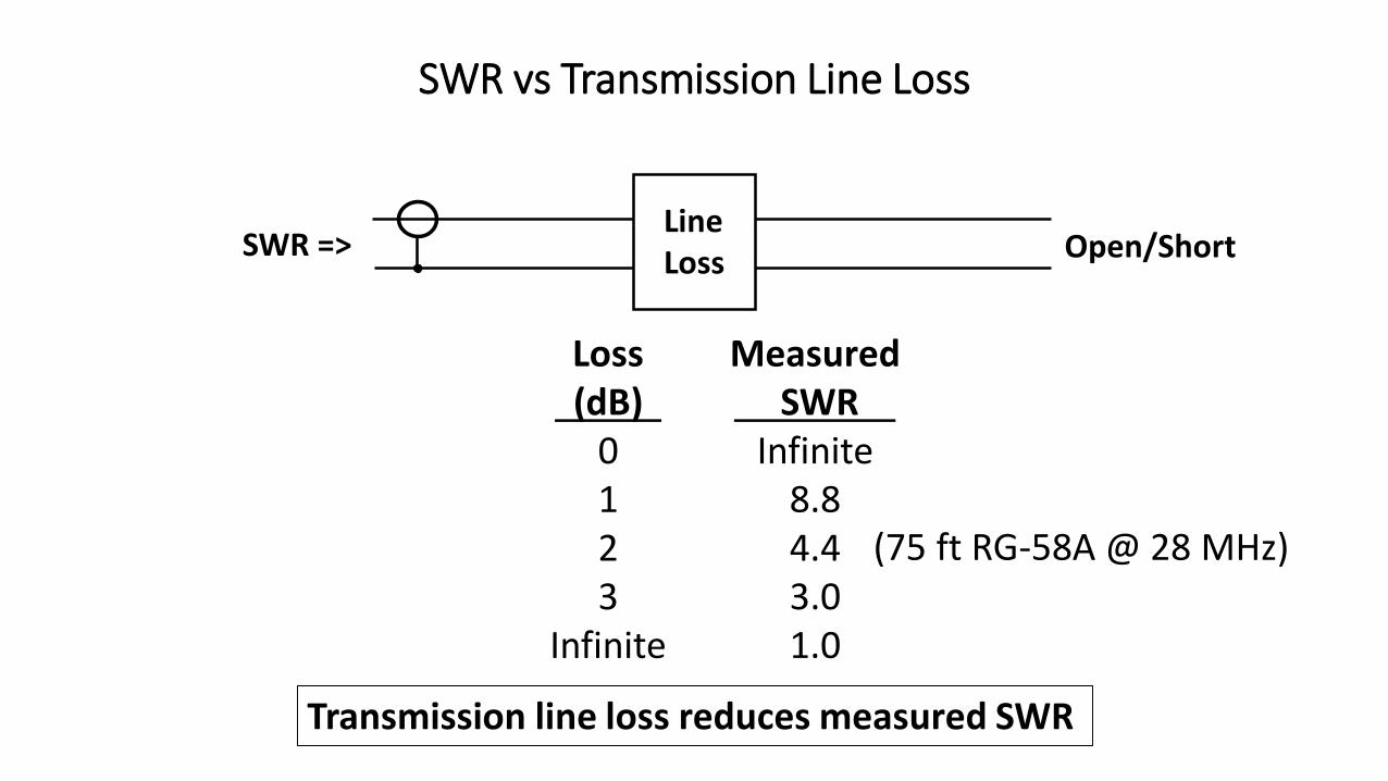
SWR vs Transmission Line Loss
Loss(dB)
0123
Infinite
SWR =>LineLoss
MeasuredSWR
Infinite8.84.43.01.0
Open/Short
Transmission line loss reduces measured SWR
(75 ft RG-58A @ 28 MHz)

• Make sure you understand the impedance measurement you are getting from your antenna analyzer
• When ZLOAD = ZO, transmission lines can become impedance transformers• This behavior can either be helpful or harmful
• The Smith chart:• Is a good learning tool
• Is not the easiest way to solve impedance problems
• Adding a short length of transmission line might help an antenna tuner achieve a match• Because it raises the impedance (it does not lower the SWR!)
• It is usually better to tune an antenna for best SWR rather than resonance
• Transmission line loss lowers the measured SWR
Summary