Embed Size (px)
Citation preview

1
Transmission Media
Key Learning Points
•Characteristics of Transmission Lines
•Transmission Line Models
•Characteristic Impedance and Impedance Matching
•Antenna Characterization
•Antenna Field Pattern
•Antenna Gain
•Antenna Design

2
• wire carries signal (current and voltage)• cable includes wire, connectors, insulation, etc.
Transmission Lines
goal: efficiently transfer signal energy from source to load over a cable
high frequency issues• line and load impedance• termination• signal reflections
3
Low Frequency Signals• primarily a resistive circuit that depends on wire thickness• thicker wires carry more current without overheating• thinner wires have higher resistance
Vdrop = IRwire
Rwire = wire resistance, depends on thickness and length
e.g. WG 22 = 16.5/1000ft
Higher Frequencies require more accurate model• transmission line modeled as RLC circuit• depends on material, diameter, spacing, insulation• L & C are negligible at low frequencies, significant at high frequencies

4
magnitude due to voltage/current ratio looking into cable• determined by L & C• affect is similar to LPF • affects amplitude, phase and system ground
properties of Z0
• characterizes wire at varying signal frequencies • determines efficiency of signal energy propagation• optimal value relative to source and load impedance
Z0 = characteristic impedance of line

5
Z = impedance ratio of voltage to current
v = Ri
v = dt
diL
i = C dt
dv
V = RI
V = jwLI
V = I . jwC
time frequency Z
R
jwL
1 = - j jwC wC
Z = R + jX• R = resistance• X = reactance• X > 0 inductive impedance (current lags voltage)• X < 0 capacitive impedance (current leads voltage)

6
G = conductance • inverse of dielectric resistance between shield & conductor• results from small current leakage between them
R = DC resistance of wire, proportional to length & thickness
C = wire’s inherent capacitance
L = wire’s inherent inductance
power transfer from source to line • maximum when impedances are complex conjugate (R jX)• impedance mismatch results in wasted energy
7
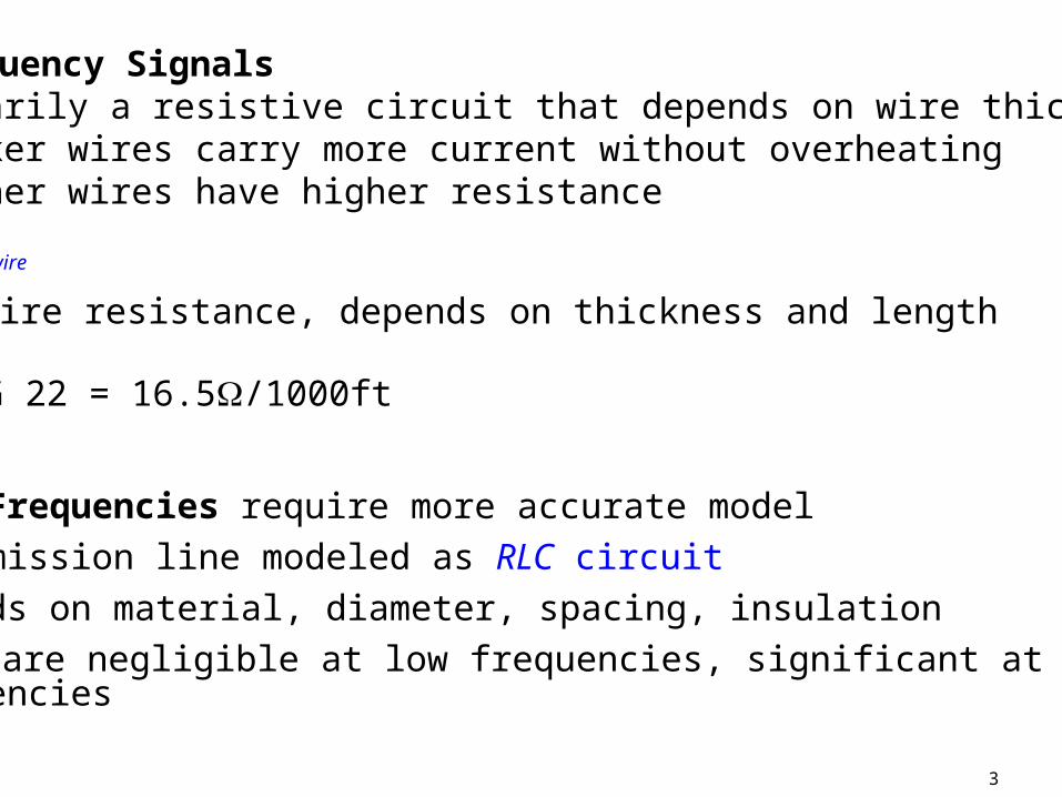
Lumped Sum Parameter Model - Coax Cable• uses discrete R,L,C,G components• physically, parameters exist continuously over cable, specified in electrical units per meter
C = shunt capacitanceG = shunt conductanceR = series resistanceL = series inductance
R
C G
L R
C G
L R
C G
L

8
Z0 = impedance of infinite line lengthZ0 = impedance of finite line terminated by resistance Z0
Z0 = jwCG
jwLR
often in practice DC resistance and current leakage are very low
Z0 = C
L
jwC
jwL
9
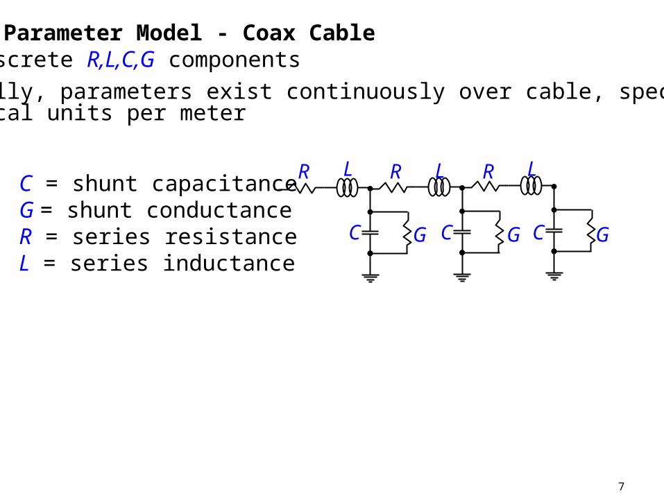
Impedance of Coaxial Cable in terms of physical dimensions
Z0 =
d
Dlog
138
D = outer coax diameterd = inner conductor diameter = dielectric constant of inner material (1.0..2.8)
Other Types of Transmission Lines with Similar Models

10
Line and Load Impedance Matching
• signal source not always a physical generator• signal load = receiver of the signal
electrical length = signal
length wire
ii f/c
length wire
Tx Rxtransmission line
source/load source/load

11
Impedance Mismatch ZL Z0
• reflections from load end cause periodic repetition of voltage voltage & current cycles
•Value of Z0 cycles from inductive to capacitive - depends on where it is measured
Impedance Matched: ZL = Z0 • transmission line terminated with Z0
• transmission line impedance is constant• flat line (non-resonant) no reflected energy – all absorbed by load
ZL = Load ImpedanceZ0 = Characteristic Impedance of Transmission Line i

12
impedance of components determined by dimensions & characteristics
• antenna• cable• transistor• amplifiers
often not practical to change impedance
goal: make signal source see desired load value - even if physical value is different

13
Stub Matching: short piece of cable with end open or shorted
• shorted end preferred – radiates less energy
• acts like a reactance, jX, placed in parallel with transmission line• varying position & length of stub stub takes on full range of jX• impedance of stub varies with position due to phase difference between current & voltage

14
Antennas & Propagation
• Antennas are designed to radiate & receive signals
• Design & selection impacted by - application - location - channel characteristics & signal propagation
• Antenna’s performance characterization - shape of the transmitted signal field - ability to reject signals to the side of main line of strength- bandwidth capabilities

15
Types of antennas
• simple antennas: dipole, long wire
• complex antennas: additional components to shape radiated fieldprovide high gain for long distances or weak signal receptionsize frequency of operation
• combinations of identical antennas - phased array electrically shape and steer antenna

16
Propagation & Antennas
transmit antenna: radiate maximum energy into surroundingsreceive antenna: capture maximum energy from surrounding
• radiating transmission line is technically an antenna • good transmission line = poor antenna
antennas are transducers- convert voltage & current into electric & magnetic field- bridges transmission line & air- similar to speaker/microphone with acoustic energy
EM field = electromagnetic field

17
Transmission Line• voltage & current variations produce EM field around conductor• EM field expands & contracts at same frequency as variations• EM field contractions return energy to the source (conductor) • All of the energy in the transmission line remains in the system
Antenna • Designed to Prevent most of Energy from returning to Conductor
• Specific Dimensions & EM wavelengths cause field to radiate several before the Cycle Reversal
- Cycle Reversal - Field Collapses Energy returns to Conductor
- Produces 3-Dimensional EM field
- Electric Field Magnetic Field
- Wave Energy Propagation Electric Field & Magnetic Field

18
transmit & receive antennas
theoretically are the same (e.g. radiation fields, antenna gain)
practical implementation issue:
transmit antenna handles high power signal (W-MW)- large conductors high power connectors,
receive antenna handles low power signal (mW-uW)
Antenna Performance depends heavily on • Channel Characteristics: obstacles, distances temperature,…• Signal Frequency• Antenna Dimensions

19
Space Wave• Line of Sight (LOS) wave • Ground Diffraction allows for greater distance• Approximate Maximum Distance, D in miles is
(antenna height in ft)• No Strict Signal Frequency Limitations
Propagation Modes
Ground or Surface wave: follow earths contour• affected by natural and man-made terrain• salt water forms low loss path • several hundred mile range• 2-3 MHz signal
rxtx hh 22 D =
hrxhtx
20
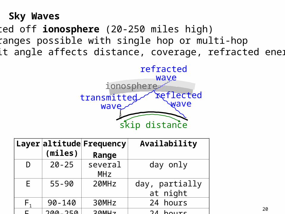
Sky Waves
ionospheretransmitted
wavereflected
wave
refracted wave
skip distance
• reflected off ionosphere (20-250 miles high)• large ranges possible with single hop or multi-hop• transmit angle affects distance, coverage, refracted energy
Layer altitude (miles)
Frequency
Range
Availability
D 20-25 several MHz day onlyE 55-90 20MHz day, partially at nightF1 90-140 30MHz 24 hoursF2 200-250 30MHz 24 hours

21
Satellite Waves
Designed to pass through ionosphere into space• uplink (ground to space) • down link (space to ground)• LOS link
frequencies >> critical frequency • penetrates ionosphere without reflection• high frequencies provide bandwidth
geosynchronous orbit 23k miles (synchronized with earth’s orbit)• long distances result in high path loss• EM energy disperses over distances• intensely focused beam improves efficiency

22
total loss = Gt + Gr – path loss (dB)
Free Space Path Loss equation used to determine signal levels over distance
G = antenna gain: projection of energy in specific direction• can magnify transmit power• increase effective signal level at receiver
24
c
fd
P
P
r
t
c
fd4log20 10 (dB)

23
Antenna Characterization
EM field pattern developed by antenna• not always possible to model mathematically• difficult to account of obstacles• antennas are studied in EM isolated rooms to extract key performance characteristics
absolute value of signal intensity varies for given antenna design- at transmit antenna is related to power applied at transmitter- at receive antenna is related to power in surrounding space
relative signal intensity used relative field pattern determined by antenna design

24
forward gain = 10dBbackward gain = 7dB
+10dB+7dB
+ 4dB
0o
270o
180o
90o
beamwidth
null
Polar Plot of relative signal strength of radiated field• shows how field strength is shaped• generally 0o aligned with major physical axis of antenna• most plots are relative scale (dB)
- maximum signal strength location is 0 dB reference- closer to center represents weaker signals

25
radiated field shaping lens & visible light• application determines required direction & focus of signal • antenna characteristics
- radiation field pattern- gain- lobes- beamwidth- directivity
• far-field measurements measured many wavelengths away from antenna
• near-field measurement involves complex interactions of decaying electrical and magnetic fields
- complicated details of antenna design involve near-field measurements
antenna field pattern = general shape of signal intensity in far-field

26
Measuring Antenna Field Pattern
field strength meter used to measure field pattern• indicates amplitude of received signal• calibrated to receiving antenna• relationship between meter and receive antenna known
measured strength in uV/meterreceived power is in uW/meter
• directly indicates EM field strength

27
Determination of overall Antenna Field Pattern form Radiation Polar Plot Pattern
• use nominal field strength value (e.g. 100uV/m) • measure points for 360o around antenna • record distance & angle from antenna• connect points of equal field strength
0o
270o
180o
90o
100 uV/m
practically • distance between meter & antenna kept constant• antenna is rotated • plot of field strength versus angle is made

28
Why Shape the Antenna Field Pattern ?
• transmit antennas: produce higher effective power in direction of intended receiver• receive antennas: concentrate energy collecting ability in direction of transmitter
- receiver only picks up intended signal• avoid unwanted receivers:
- security- multi-access systems
• locate target direction & distance – e.g. radar• not always necessary to shape field pattern• standard broadcast often omnidirectional - 360o
29
Gain is Measured Specific to a Reference Antenna• isotropic antenna often used - gain over isotropic
- isotropic antenna – radiates power ideally in all directions
- gain measured in dBi (reference to isotropic antenna)
- test antenna’s field strength relative to reference isotropic antenna
- at same power, distance, and angle
- isotropic antenna cannot be practically realized
• ½ wave dipole often used as reference antenna- easy to build- simple field pattern
Antenna Gain

30
Antenna Gain Amplifier Gain
• antenna power output = power input – transmission line loss
• antenna shapes radiated field pattern
• power measured at a point is greater/less than that using reference antenna
• total power output doesn’t increase
• power output in given direction increases/decreases relative to reference antenna

31
• lamp isotropic antenna • lens directional antenna
lens provides a gain/loss of visible light in a specific direction lens doesn’t change actual power radiated by lamp
e.g.transmit antenna with 6dB gain in specific direction over isotropic antenna 4 transmit power in that direction
receive antenna with 3dB gain is some direction receives twiceas much power than reference antenna

32
Antenna Gain often a cost effective means to
(i) increase effective transmit power(ii) effectively improve receiver sensitivity
may be only technically viable means• more power may not be available (batteries)• front end noise determines maximum receiver sensitivity
Rotational Antennas can vary direction of antenna gain
Directional Antennas focus antenna gain in primary direction

33
Antenna Design results in Beamwidth, Lobes & Nulls
Lobe: area of high signal strength- main lobe - secondary lobes
Nulls: area of very low signal strength
Beamwidth: total angle where relative signal power is 3dB below peak value of main lobe
- can range from 1o to 360o
Beamwidth & Lobes indicate sharpness of pattern focus
null
beamwidth lobe

34
Antenna Design – Spectral Parameters
Center Frequency - optimum operating frequency
Antenna Bandwidth -3dB points of antenna performance
Bandwidth Ratio: Bandwidth/Center Frequency
e.g. let fc = 100MHz with 10MHz bandwidth
- radiated power at 95MHz & 105MHz = ½ radiated power at fc
- bandwidth ratio = (105-95)/100 = 10%

35
Bandwidth Issues• High Bandwidth Antennas tend to have less gain than narrowband antennas
• Narrowband Receive Antenna - reduces interference from adjacent signals- reduces received noise power
main trade-offs for Antenna Design• directivity & beam width• acceptable lobes• maximum gain• bandwidth• radiation angle

36
552.14 dB
Dipole
3600 dB
Isotropic
Beamwidth -3 dB
Gain (over isotropic)
ShapeName Radiation Pattern
20
30
50
200
25
14.7 dB
10.1 dB
-0.86 dB
3.14 dB
7.14 dB
Parabolic Dipole
Helical
Turnstile
Full Wave Loop
Yagi
Biconical Horn
1515 dBHorn
360x20014 dB