Embed Size (px)
Citation preview

Građevinar 7/2019
589GRAĐEVINAR 71 (2019) 7, 589-600
Authors:
Primljen / Received:
Ispravljen / Corrected:
Prihvaćen / Accepted:
Dostupno online / Available online:
DOI: https://doi.org/10.14256/JCE.2350.2018
12.9.2018.
25.2.2019.
19.5.2019.
10.8.2019.
Track ballast modelling by discrete element method
Viktorija Sluganović, MCEUniversity of ZagrebFaculty of Civil [email protected]
Prof. Stjepan Lakušić, PhD. CEUniversity of ZagrebFaculty of Civil [email protected]
Prof. Damir Lazarević, PhD. CEUniversity of ZagrebFaculty of Civil [email protected]
Subject review
Viktorija Sluganović, Stjepan Lakušić, Damir Lazarević
Track ballast modelling by discrete element method
An increase in axle load and travel speed causes faster degradation of track structure and, hence, of the ballast prism. Crushing of stone grains in ballast due to excessive contact forces among these grains causes degradation in the form of filling of voids and, in turn, in poorer drainage, which can cause structural failure. The degradation of ballast prism can significantly be reduced, and total maintenance costs can be cut down considerably, by optimizing frequency of maintenance activities and by proper ballast design and shaping based on numerical and experimental procedures. The possibilities of using the discrete element method for predicting track ballast behaviour are presented in this paper.
Key words:
railway track, ballast prism, prism degradation, numerical modelling, granular material
Pregledni rad
Viktorija Sluganović, Stjepan Lakušić, Damir Lazarević
Modeliranje kolosiječnog zastora metodom diskretnih elemenata
Povećanje osovinskog opterećenja i brzine prometovanja kolosijekom utječe na bržu degradaciju kolosiječne konstrukcije, posebice zastorne prizme. Drobljenje kamenih zrna unutar zastora zbog prevelikih kontaktnih sila među njima, uzrokuje degradaciju u vidu zapunjavanja šupljina što dovodi do slabije odvodnje koja može prouzročiti slom konstrukcije. Optimizacijom učestalosti održavanja i pravilnim oblikovanjem zastora temeljenih na numeričkim i eksperimentalnim postupcima, može se utjecati na proces degradacije zastorne prizme, a time i na ukupne troškove održavanja. U ovom radu prikazane su mogućnosti metode diskretnih elemenata u predviđanju ponašanja kolosiječnog zastora.
Ključne riječi:
željeznički kolosijek, zastorna prizma, degradacija prizme, numeričko modeliranje, zrnati materijal
Übersichtsarbeit
Viktorija Sluganović, Stjepan Lakušić, Damir LazarevićModellierung eines gekrümmten Ballastprismas mit diskreten Elementen
Das Erhöhen der Achslast und der Verkehrsgeschwindigkeit auf dem Gleis wirkt sich auf die schnellere Verschlechterung der Gleiskonstruktion, insbesondere des Ballastprismas aus. Das Zerkleinern von Steinkörnern innerhalb des Ballasts aufgrund übermäßiger Kontaktkräfte zwischen ihnen führt zu einer Verschlechterung in Form von Hohlräumen, was zu einer schwächeren Drainage führt, die einen Zusammenbruch der Struktur verursachen kann. Die Optimierung der Wartungshäufigkeit und die ordnungsgemäße Gestaltung von Ballasten auf der Grundlage numerischer und experimenteller Verfahren können den Abbauprozess des Ballastprismas und damit die Gesamtwartungskosten beeinflussen. In dieser Arbeit werden die Möglichkeiten der Methode der diskreten Elemente bei der Vorhersage des Verhaltens des Gleisballasts vorgestellt.
Schlüsselwörter:Bahngleis, Ballastprisma, Prismenverschlechterung, numerische Modellierung, körniges Material
Građevinar 7/2019
590 GRAĐEVINAR 71 (2019) 7, 589-600
Viktorija Sluganović, Stjepan Lakušić, Damir Lazarević
1. Introduction
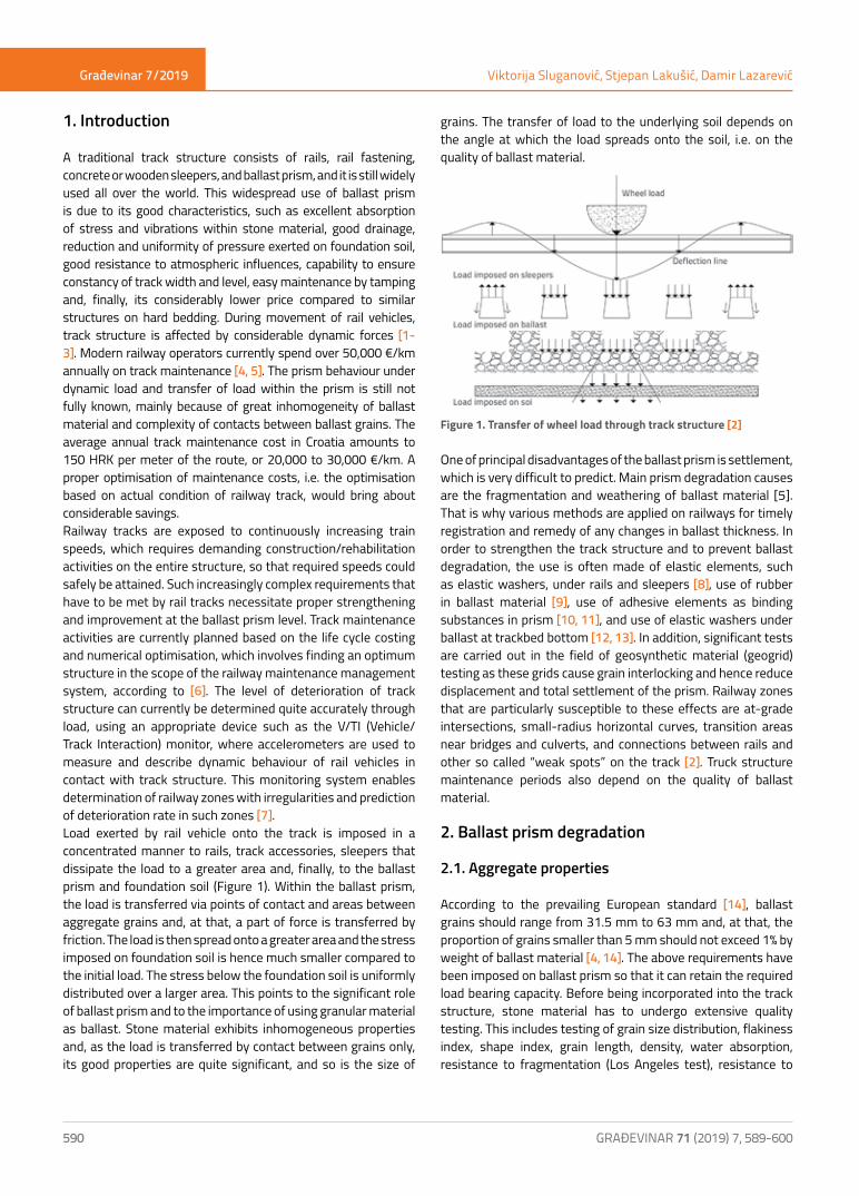
A traditional track structure consists of rails, rail fastening, concrete or wooden sleepers, and ballast prism, and it is still widely used all over the world. This widespread use of ballast prism is due to its good characteristics, such as excellent absorption of stress and vibrations within stone material, good drainage, reduction and uniformity of pressure exerted on foundation soil, good resistance to atmospheric influences, capability to ensure constancy of track width and level, easy maintenance by tamping and, finally, its considerably lower price compared to similar structures on hard bedding. During movement of rail vehicles, track structure is affected by considerable dynamic forces [1-3]. Modern railway operators currently spend over 50,000 €/km annually on track maintenance [4, 5]. The prism behaviour under dynamic load and transfer of load within the prism is still not fully known, mainly because of great inhomogeneity of ballast material and complexity of contacts between ballast grains. The average annual track maintenance cost in Croatia amounts to 150 HRK per meter of the route, or 20,000 to 30,000 €/km. A proper optimisation of maintenance costs, i.e. the optimisation based on actual condition of railway track, would bring about considerable savings. Railway tracks are exposed to continuously increasing train speeds, which requires demanding construction/rehabilitation activities on the entire structure, so that required speeds could safely be attained. Such increasingly complex requirements that have to be met by rail tracks necessitate proper strengthening and improvement at the ballast prism level. Track maintenance activities are currently planned based on the life cycle costing and numerical optimisation, which involves finding an optimum structure in the scope of the railway maintenance management system, according to [6]. The level of deterioration of track structure can currently be determined quite accurately through load, using an appropriate device such as the V/TI (Vehicle/Track Interaction) monitor, where accelerometers are used to measure and describe dynamic behaviour of rail vehicles in contact with track structure. This monitoring system enables determination of railway zones with irregularities and prediction of deterioration rate in such zones [7].Load exerted by rail vehicle onto the track is imposed in a concentrated manner to rails, track accessories, sleepers that dissipate the load to a greater area and, finally, to the ballast prism and foundation soil (Figure 1). Within the ballast prism, the load is transferred via points of contact and areas between aggregate grains and, at that, a part of force is transferred by friction. The load is then spread onto a greater area and the stress imposed on foundation soil is hence much smaller compared to the initial load. The stress below the foundation soil is uniformly distributed over a larger area. This points to the significant role of ballast prism and to the importance of using granular material as ballast. Stone material exhibits inhomogeneous properties and, as the load is transferred by contact between grains only, its good properties are quite significant, and so is the size of
grains. The transfer of load to the underlying soil depends on the angle at which the load spreads onto the soil, i.e. on the quality of ballast material.
Figure 1. Transfer of wheel load through track structure [2]
One of principal disadvantages of the ballast prism is settlement, which is very difficult to predict. Main prism degradation causes are the fragmentation and weathering of ballast material [5]. That is why various methods are applied on railways for timely registration and remedy of any changes in ballast thickness. In order to strengthen the track structure and to prevent ballast degradation, the use is often made of elastic elements, such as elastic washers, under rails and sleepers [8], use of rubber in ballast material [9], use of adhesive elements as binding substances in prism [10, 11], and use of elastic washers under ballast at trackbed bottom [12, 13]. In addition, significant tests are carried out in the field of geosynthetic material (geogrid) testing as these grids cause grain interlocking and hence reduce displacement and total settlement of the prism. Railway zones that are particularly susceptible to these effects are at-grade intersections, small-radius horizontal curves, transition areas near bridges and culverts, and connections between rails and other so called “weak spots” on the track [2]. Truck structure maintenance periods also depend on the quality of ballast material.
2. Ballast prism degradation
2.1. Aggregate properties
According to the prevailing European standard [14], ballast grains should range from 31.5 mm to 63 mm and, at that, the proportion of grains smaller than 5 mm should not exceed 1% by weight of ballast material [4, 14]. The above requirements have been imposed on ballast prism so that it can retain the required load bearing capacity. Before being incorporated into the track structure, stone material has to undergo extensive quality testing. This includes testing of grain size distribution, flakiness index, shape index, grain length, density, water absorption, resistance to fragmentation (Los Angeles test), resistance to

Građevinar 7/2019
591GRAĐEVINAR 71 (2019) 7, 589-600
Track ballast modelling by discrete element method
wear, etc. To provide for better grain interlocking and to ensure proper resistance to dynamic load in the longitudinal and transverse directions, an advantage is given to polyhedral grains rather than to rounded grains (pebbles). During the tamping process, but also due to the passage of railway vehicles, ballast grains are gradually rounded, their edges break off as they are subjected to greatest load, and hence the interlocking capacity is reduced [10, 15].The grain size distribution property of prism material is highly significant for load transfer. Over time, grains break off and crush and, consequently, the bearing capacity is gradually weakened. The proportion of fines and the percent retained on sieve are shown in Figure 2 for new clean ballast and for ballast in use [2]. A significant increase in the quantity of fine fractions can be noticed for aggregate in use, i.e. the proportion of 0.1 mm grains exceeds by more than five times that found in new aggregate. The capacity for transferring great load is reduced in case of fine aggregate grains and so the degradation process accelerates once a critical aggregate grading is reached.
2.2. Degradation and fouling of ballast
Ballast settlement occurs due to insufficient bearing capacity of material, excessive loads, atmospheric influences, inadequate grading of ballast material but, ultimately, ballast settlement is a function of axle load.
Figure 3. Settlement as a function of increase in load [12]
An increase in ballast settlement over time, as related to an increase in axle load from 5.6 kN to 118.2 kN, is shown in Figure 3 [16]. Ballast settlement causes disturbance in the vertical geometry of the track, which negatively affects traffic safety and passenger comfort [16].Track structures are subjected to cyclic load, and failure due to cyclic load is sudden and occurs at load levels that are lower compared to static load. Track structure behaviour under dynamic load is complex and depends on a number of factors, such as the state and history of load and, in the case of granular material, it is also dependent on external conditions [2].
Figure 4. a) Vertical displacements with an increase in track depth, b) stress in ballast prism with the change in depth [2]
Figure 2. Proportion of fines and the percent retained on sieve for clean and fouled ballast [2]

Građevinar 7/2019
592 GRAĐEVINAR 71 (2019) 7, 589-600
Viktorija Sluganović, Stjepan Lakušić, Damir Lazarević
To better understand behaviour of structures under cyclic load, it is important to start by examining their behaviour under static load. One of principal properties of the ballast prism is the way the load is transferred and spread onto the underlying surface and, at that, the load exerted on the underlying surface is much smaller compared to that in the ballast layer. This load reduction is due to friction between grains that assume most part of the load. Ballast prism and foundation soil displacements are shown in Figure 4a). Stresses occurring within layers are also presented. It can be observed that stress is much greater and deflection is smaller in the ballast layer. As the stiffer ballast layer lies on the softer foundation soil, the corresponding change in curve slope can be observed on the stress diagram at the contact between the foundation soil and ballast, [2]. The transfer of load onto foundation soil has been an interesting area of research in all parts of the world ever since the earliest days of railway transport; it is today approximated according to various authors [5, 17].Stress distribution in ballast prism also depends on its thickness, as shown in Figure 4.b, for prisms 15 cm, 30 cm, and 61 cm in thickness. The analysis of stress for various ballast prism thicknesses is highly significant in the development of methods for predicting settlement rate of track structures. The change in volume at cyclic load causes deformations in ballast layer due to redistribution of grains, and a denser structure is created. At that, partial crushing of ballast grains occurs, and smaller ones enter the empty space between larger grains. Grain crushing is caused by an increase in contact forces between grains, but also by freezing and thawing cycles and chemical effects from the surrounding area. The settlement of ballast prism is also caused by additional vibrations of passing rail vehicles, because of their influence on the redistribution and displacement of ballast grains. After a number of years and following the corresponding passage of rail vehicles, the ballast prism is filled with fine grains due to poor properties of the underlying soil, which causes poor drainage and leads to plastic occurrences within the ballast, instead of the necessary elastic behaviour. The prism filling effect is mostly exhibited during maintenance by tamping when finer grains fall to the bottom of prism, and are compressed by remaining ballast grains; the transfer to foundation soil is not sufficient, and so the stress values remain high. The crushed ballast grains influence deformation and strength of the ballast material, as well as the overall behaviour of the track structure. The ballast crushing occurs at the points of contact between grains and, over time, with an increase in load, larger fragments of stone material are cut off as well. This contributes to differential settlement of the track and also to transverse deformation, as lateral resistance is also insufficient [4]. The level of fragmentation is determined by means of the Los Angeles abrasion (LAA) test. This test can be used to determine the aggregate strength and the probability of fracturing or fragmentation below the track sleepers. The life span and degradation of aggregate grains in ballast prism are greatly affected by the tamping procedure during usual track maintenance activities [18]. This track tamping activity is performed to bring back the track level to the design height, to ensure better distribution of grains and to fill the voids below sleepers, so as to provide for an appropriate transfer of load from sleepers to the
ballast prism. This grain redistribution causes a renewed wear and crushing of ballast material, which accelerates the degradation process and reduces durability of ballast material. Prism filling is one of principal causes of deterioration and settlement of the ballast prism, but also of a reduced effect of tamping, i.e. of a reduced time in which tamping is effective [19].That is why great efforts are made to correctly define maintenance cycles, so as to reduce prism maintenance costs and ballast wear due to tamping by reducing frequency of maintenances activities. The objective is to create numerical models capable of predicting ballast settlement. Such models enable operators to define optimum ballast tamping intervals.
3. Use of discrete element method for numerical modelling of ballast prism
The settlement of ballast material occurs due to redistribution of grains as caused by cyclic load and other factors. It lowers the level of traffic safety and riding comfort; however, the correction of track structure is associated with the use of expensive equipment. That is why attempts are nowadays made to create numerical models that could be used to estimate in advance the way in which ballast prism will behave [16]. Thus, what we wish to achieve by numerical modelling, experimental, laboratory or in situ testing is proper prediction of aggregate grain behaviour within the prism structure. If it is possible to predict in advance activities taking place within the prism, then it would also be possible to simply determine critical spots (important for maintenance) along the track, and to realise such spots with appropriate “strengthening”. The objective behind the study of this problem is to achieve a proper design ballast prism, by determining in advance the behaviour and force transfer, and by using this information to define grain properties. Due to discrete nature of aggregate, it would not be sufficient to observe this part of the track as a continuum, but rather the discontinuum must be applied. Contrary to the continuum mechanics problems (that are described by differential equations), the problems of discontinuum mechanics describe behaviour and interaction between grains. The use of computers is indispensable for solving such problems [20]. To monitor ballast behaviour and the effects of various procedures for ensuring long-term stability, various monitoring and numerical modelling methods are currently used in the control and prediction of ballast behaviour Prism behaviour is markedly nonlinear and is dependent on a number of factores, and the corresponding computations are conducted with some simplifications. In a traditional track structure, the ballast prism and the foundation soil are relatively far away from the contact area between the wheel and the rail, where dynamic forces are generated due to irregularities at the the running surface of the wheel and the edge of the rail.Complex numerical analyses are conducted in recent times to evaluate the prism behaviour and life span of the track structure. Results obtained by numerical modelling of track structures have not been implemented due to poor knowledge of grain interaction mechanisms. The time needed for numerical analysis of the structure is also a limiting factor of such procedures.

Građevinar 7/2019
593GRAĐEVINAR 71 (2019) 7, 589-600
Track ballast modelling by discrete element method
This factor greatly influence selection of the grain shape, grain interaction mechanisms, volume of the area that is modelled, etc. Additional assumptions are being introduced in order to reduce the time needed for the analysis, which influences the accuracy of results. The procedure that is most often used in the ballast prism modelling is based on the discrete element method, which can be used for modelling the discrete nature of granular materials, [22]. In some prism models based on the discrete element method, ballast grains are regarded as being absolutely stiff, and special attention is attributed to contact forces between grains.
3.1. Numerical models of grains and contact
Investigations based on the discrete element method (DEM), conducted by Liu at al. [23], have shown that ballast behaviour is significantly influenced by grain shape. DEM modelling can be used to gain insight into an appropriate grain size and it also enables determination of the most favourable shape for use in the track structure. According to various authors, granular material is modelled by polyhedral convex elements [24], or, in simpler terms, by spherical elements. Spherical clusters, which can properly represent the real behaviour of ballast grains, are also used [25]. Spheres enable faster computation due to faster neighbour search and simpler definition of contact areas. Regardless of initial simplicity of such models, current models based on sphere use have become much more complex. Stone grains are presented as clusters of such elements, and so the search and behaviour of contacts have become more complex. This has enabled creation of a more realistic model of prism material behaviour. Modelling with polyhedral elements is much more complex and requires time-consuming computations. According to [24], greater shear strength of the prism modelled with polyhedral elements as related to spheres is caused by anisotropic properties and better interlocking of elements. Ballast behaviour is also well represented with spherical clusters, in which individual units consist of two, four,
or eight elements [26]. Various studies have shown that prisms with elongated and flat stone grains do not exhibit good results when subjected to loading [27]. Grain crushing is also taken into account by some researchers. This approach is a significant step toward a more realistic representation of grain behaviour as grain crushing is one of principal causes of track structure degradation. At that, a significant role is assumed by the quality of aggregate material. Grain crushing is most often modelled in two ways: using multi-part elements attached to the grain element which break off due to exceedance of the defined maximum stress in the layer, and using maximum stress that causes separation of elements into segments. The situation in the ballast prism model due to crushing defined by PFC 3D software is presented in figure 5 [28].During model development, a special attention is paid to the modelling of contact surfaces and to the behaviour of contact between elements, i.e. to the load transfer. When polyhedral elements are used, forms of contact are defined in four possible ways: top-surface (one contact point), edge-edge, surface-surface (three contact points) and edge-surface (two contact points); Figure 6 [24]. The surface-surface contact, in which the contact is defined via three points, is the strongest bond.
Figure 6. Types of contact points and surfaces between polyhedral elements [19]
Figure 5. Condition of ballast grains during use: a) new clean ballast grains, b) ballast grains with a small quantity of smaller grains, c) ballast grains with a greater quantity of smaller grains (fines) [23]
Figure 7. a) Grain triangulation, b) the same grain composed of 5 and 34 spheres, c) tetrahedral grid of a spherical grain [24]

Građevinar 7/2019
594 GRAĐEVINAR 71 (2019) 7, 589-600
Viktorija Sluganović, Stjepan Lakušić, Damir Lazarević
Behaviour can be represented more realistically with an increase in the number of spheres, as a greater asperity can thus be achieved. Arbitrary form of a polyhedral grain can be replaced with spheres which approximately represent the form of the grain and provide sufficiently good results at a shorter computation time; figures 7 and 8, [25, 29].An important process taking place in the stone material is the fragmentation of weakened parts of the ballast prism [30]. The fragmentation of heterogeneous brittle material occurs in various time periods, and can be caused by ageing due to atmospheric influences or sudden fracturing of the stone.
Figure 8. Ballast grain models [25]
In the computer software EDEM, polyhedral elements are divided into smaller polyhedral elements with rough edges, regardless of whether the fracture occurred due to atmospheric actions or by sudden fracturing due to load beyond the maximum one (Figure 9).
Figure 9. Fragmentation model of a polyhedral element [31]
At that, the fracturing occurs along the fracture plane of the element which runs through the centre of mass of the element, and the masses of the formed elements are equal. A part of the element that will be subjected to fragmentation is selected according to the length of the edge along which the fracturing can occur. One of the reasons why the discrete element method is applied for this type of problems is that contacts of grains
constantly change in the numerical model. If the contact between all grains in the packing were checked, this would extend the computation time considerably [30]. The aggregate fracture mechanism can be set via algorithm in which polyhedral elements always break into two parts along the plane passing through the centre of mass of the element and, at that, the form of the element is arbitraryn [31].
3.2. Contact force models
The interaction of stone material grains, their displacements, rotations and force transfer, depend on grain contact mechanisms. Contact models that are frequently used for presenting and defining mechanisms of contact between grains in DEM are: linear model, Hertz model and Hertz-Mindlin model. Principal equations for contact actions are presented below.
Figure 10. Contact forces between spheres [20, 28]
Grains in contact and interaction force are shown in Figure 10. In calculations based on DEM method, most time is spent in contact search activities. The simplest determination of interaction is based on verification of contact of each sphere with every other sphere. As this approach is extremely time-consuming, numerous algorithms can be used to reduce the scope of search [25]. Once the contact between two grains (elements) has been defined, the forces in contact points are calculated. The contact between two spheres that are in interaction can be written as follows:
Fij = - Fij (1)
where the force has the normal and tangential components .
Consequently, the following can be written:
= + = + (2)
Where nij the unit vector is perpendicular to the surface of the grain in contact point between grains i i j. This unit vector lies on the straight line of the centres of two grains, and is directed outside of the grain (Figure 11). Contact forces , and are defined by the constitutional model of contact between grains. Local material models that are usually used in DEM are described in [25].

Građevinar 7/2019
595GRAĐEVINAR 71 (2019) 7, 589-600
Track ballast modelling by discrete element method
Figure 11. Contact force division into normal and tangential components [28]
Figure 12. Model: a) standard contact 32]; b) penetration [25]
The Hertz contact model, presented in Figure 12, takes into account the curvature of contact surfaces. When one body touches another, the contact point is deformed, but the contact surface is very small compared to the dimensions of the body. The shape and increase of the surface, and distribution of stress along the surface, are determined by the contact body geometry and loads. Such contact model can be applied only in cases of static load or when the impact velocity is very small. Limitations of impact velocity depend of the density and Young’s modulus of elasticity, which define criteria for the determination of the maximum impact velocity that is valid for the Hertz model. If we have two spheres of radius r1 and r 2, the contact surface is the circle of radius a, as shown in Figure 13.
Figure 13. Schematic view of the Hertz contact model [20]
The linear-elastic contact model is less often used than the Hertz model and the Hertz-Mindlin model as, in the case of stone grain
modelling, it is important to take into account a good shape of the grain, which is better represented with the Hertz and Hertz-Mindlin models [33]. The Hertz-Mindlin model is a combination of the Hertz model and the Mindlin model in which the Hertz theory is applied in normal direction, while the Mindlin’s improved method is applied in transverse direction. This combination in DEM was first used by Di Renzo and Di Maio [34].
3.3. Use of discrete element method in ballast analysis
According to [35], fragmentation of stone material results in an increase in the number of contacts between grains, while at the same time the values of contact forces decrease. The assumed cause is an elastic behaviour of fine grains that form bigger aggregate grains and reduce the value of contact forces, which in turn reduces grain degradation. Numerical calculations have been conducted to investigate the influence of various track strengthening materials in order to determine their usefulness. In the scope of one of such investigations the installation of geogrid in ballast prism has been tested, Figure 14, [29, 30, 36].
Figure 14. Models of new ballast and ballast with high content of fines with the use of geogrid [25]
The use of geosynthetics, geogrids and rubber washers can significantly improve the bearing capacity and durability of traditional ballast-based track structures [35]. Results of numerical modelling of ballast strengthened with geogrids show, depending on the ballast prism condition (high or low content of fines), a good correspondence with experimental results, as shown in Figure 15 [29].

Građevinar 7/2019
596 GRAĐEVINAR 71 (2019) 7, 589-600
Viktorija Sluganović, Stjepan Lakušić, Damir Lazarević
Load transfer through ballast layer depends on the distribution of contact forces between grains. Figure 16 shows shear stresses, vertical displacements, and comparison of DEM model and experimental results, for the ballast model with various proportions of fines, strengthened with geogrid.
Some complex tests have been made possible thanks to advancement of the discrete element method. For instance, the pull-out modelling of ballast geogrid was conducted for various forms and complexities of grains [36]. The novelty in this testing lies in consistent integration of contact forces for edge
displacements and, at that, the contact point sliding along the external edge is taken into account. The quantity of crushed detached fines exerts a considerable influence on ballast behaviour. Figure 17 shows a ballast model with various levels of aggregate fouling: from completely clean to completely fouled (all intergranular voids are filled). The ability of ballast to transfer load and perform other functions within the track structure is determined based on the quantity of material filled with fines. Good results, compliant with in situ and laboratory measurements, have been obtained by DEM model prediction of behaviour of crushed stone placed in ballast prism. An interesting comparison of test results and DEM model results for ballast, based on grading, grain shape, texture and angularity, has been made at the University of Illinois (Figure 18) [27].
Figure 15. Shear strength and volume deformation results obtained experimentally and numerically for: a) fresh ballast and b) ballast with a considerable content of fines (VCI 40%) [29]
Figure 16. Comparison of stress and vertical displacement results obtained by DEM simulation and experimental testing of fresh ballast, and geogrid resistance testing [34]
Građevinar 7/2019
597GRAĐEVINAR 71 (2019) 7, 589-600
Track ballast modelling by discrete element method
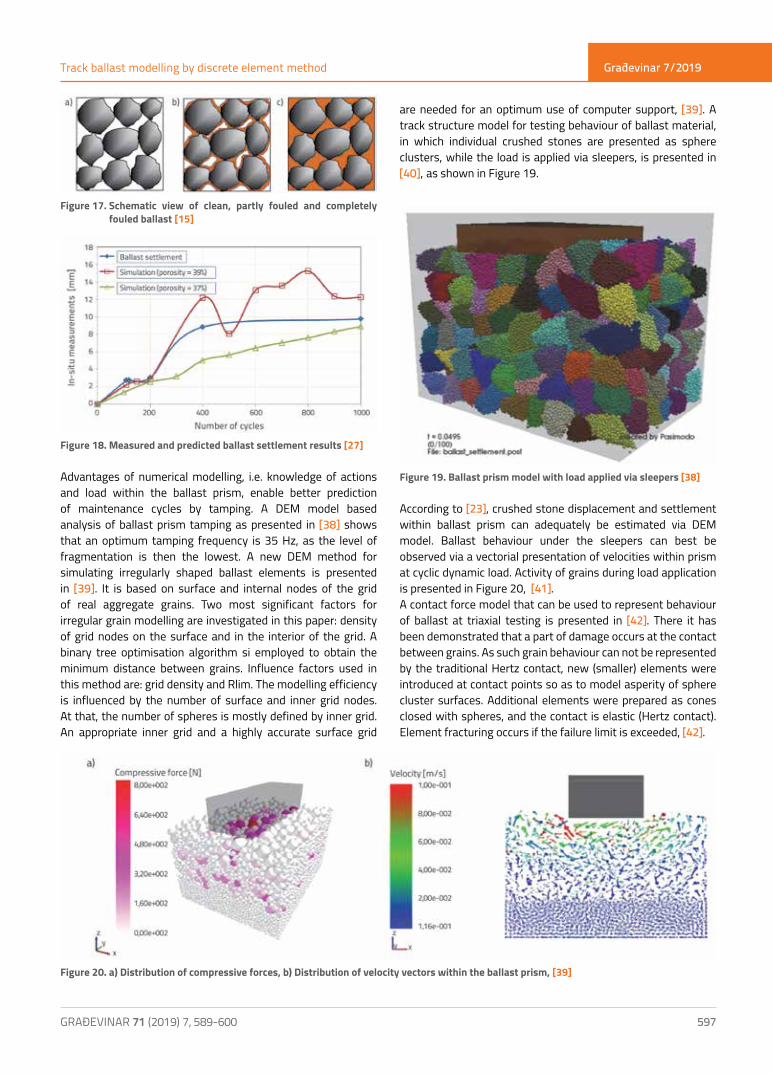
Figure 17. Schematic view of clean, partly fouled and completely fouled ballast [15]
Figure 18. Measured and predicted ballast settlement results [27]
Advantages of numerical modelling, i.e. knowledge of actions and load within the ballast prism, enable better prediction of maintenance cycles by tamping. A DEM model based analysis of ballast prism tamping as presented in [38] shows that an optimum tamping frequency is 35 Hz, as the level of fragmentation is then the lowest. A new DEM method for simulating irregularly shaped ballast elements is presented in [39]. It is based on surface and internal nodes of the grid of real aggregate grains. Two most significant factors for irregular grain modelling are investigated in this paper: density of grid nodes on the surface and in the interior of the grid. A binary tree optimisation algorithm si employed to obtain the minimum distance between grains. Influence factors used in this method are: grid density and Rlim. The modelling efficiency is influenced by the number of surface and inner grid nodes. At that, the number of spheres is mostly defined by inner grid. An appropriate inner grid and a highly accurate surface grid
are needed for an optimum use of computer support, [39]. A track structure model for testing behaviour of ballast material, in which individual crushed stones are presented as sphere clusters, while the load is applied via sleepers, is presented in [40], as shown in Figure 19.
Figure 19. Ballast prism model with load applied via sleepers [38]
According to [23], crushed stone displacement and settlement within ballast prism can adequately be estimated via DEM model. Ballast behaviour under the sleepers can best be observed via a vectorial presentation of velocities within prism at cyclic dynamic load. Activity of grains during load application is presented in Figure 20, [41]. A contact force model that can be used to represent behaviour of ballast at triaxial testing is presented in [42]. There it has been demonstrated that a part of damage occurs at the contact between grains. As such grain behaviour can not be represented by the traditional Hertz contact, new (smaller) elements were introduced at contact points so as to model asperity of sphere cluster surfaces. Additional elements were prepared as cones closed with spheres, and the contact is elastic (Hertz contact). Element fracturing occurs if the failure limit is exceeded, [42].
Figure 20. a) Distribution of compressive forces, b) Distribution of velocity vectors within the ballast prism, [39]

Građevinar 7/2019
598 GRAĐEVINAR 71 (2019) 7, 589-600
Viktorija Sluganović, Stjepan Lakušić, Damir Lazarević
As prism behaviour is highly complex, attempts have recently been made to take into account some more complex effects, such as the sleeper rotation effect, as shown in the study conducted at the Pennsylvania State University [43], where sleepers are modelled by finite elements, and crushed stone material by discrete elements. A 3-dimensional model of the track structure and prism was made using the BLOCKS3D software package. Figure 21 shows a vectorial view of grain velocity in prism model, where an increased grain model motion next to the sleeper can be seen. An increase in angular acceleration can cause load by an additional moment of 5kN, which speeds up degradation of ballast prism considerably, while also reducing durability of ballast material [43]. Obviously, sleeper movements can cause an additional moment that influences filling of track with smaller grains due to crushed stone fracturing, which reduces the service live and increases the cost of maintenance of the structure. It can be concluded that it would also be interesting to analyse the influence of other track structure elements on the ballast prism. The mixed DEM-FDM method was used by Ngo et al., [44] and, at that, the foundation soil was modelled by the FDM (finite difference method), while the ballast prism was modelled using the DEM method. In the mentioned model, the link between the DEM and FDM areas is operated by contact area elements and, at that, discrete elements are used to transfer force as input data for the finite difference method; this method is used to obtain displacements which are then returned to DEM. This investigation, [44], has revealed that the bond breaking in ballast material increases with an increase in frequency (f=15-30 Hz).In addition, stress distribution within the ballast prism is not uniform, and stress value is the greatest under the sleepers. Results were obtained by DEM models, and the area with greatest stress coincides with the zone that contains the greatest number of broken contact links between grain models. The reliability of the FEM-DEM model was confirmed by good correspondence of numerical and experimental results, [44]. The transfer of load within the prism is also influenced by the foundation soil, as it acts on an increase in stress within the prism, which is shown in the DEM model as a break in contact links [44]. The break occurs as the forces exceed the load bearing capacity of the material at the point of contact, and the transfer of load along the contact or by the contact is no longer possible. According to the FEM - DEM model [45], the sleeper
settlement in vertical direction occurs due to redistribution of stone grains and as a result of settlement of the foundation soil. Ballast behaviour over a longer period of time is still not fully known, because of time-consuming calculations for even the simplest models of behaviour of grains as solid bodies. During the FEM - DEM model development, a special attention must be paid to the link between model parts that have been prepared using different methods. Thus, according to Shao et al. [45], contact forces determined by the DEM method in the ballast part actually represent external forces for the FEM method. Deformations calculated by FEM represent boundary conditions for DEM. It is necessary to conduct additional linking as external forces acting on the FEM model have to be placed in grid nodes, while the values in the DEM model do not act precisely in nodes. Contact forces obtained by the DEM analysis are used to calculate equivalent forces in finite element nodes based on the principle of virtual work. The virtual work of contact forces amounts to:
(3)
where Fcon is the force vector in contact points between the grain model and top surface of the foundation soil, U is the node displacement in which the contact occurs, and can be expressed as the product of node displacement and shape function of the FEM method, [45].
Figure 22. Load transfer in the combined FEM-DEM model [44]
The combination of the OOFEM and DEM codes for modelling sleeper and ballast interaction using the YADE software has also been presented by Stransky [46]. The way in which load transfer is operated in the model is presented schematically in Figure 22, and the load obtained by the DEM calculation is in this case also defined in the FEM model, while displacements obtained by the FEM method become input data for the DEM model.
Figure 21. Vectorial view of contact forces in the prism model: a) without sleeper rotation, b) with sleeper rotation [41]

Građevinar 7/2019
599GRAĐEVINAR 71 (2019) 7, 589-600
Track ballast modelling by discrete element method
5. Conclusion
With an increase in the speed of travel and axle load, the track ballast prism degradation has become a significant problem in the maintenance of track structures. The condition of ballast prism influences service life of the track structure, as well as the riding comfort and safety; this is why ballast prism behaviour must be studied to enable timely detection and appropriate remedy of any change in this segment. For that reason, various monitoring methods and numerical simulations have increasingly been used in this field. This paper provides a review of investigations related to modelling based on the discrete element method, which enables an accurate simulation of static and dynamic behaviour of stone material used in ballast prisms. The stability and behaviour of the entire track structure greatly depends on displacements and actions within the ballast. Various grain fracturing possibilities are introduced, and then interaction within the system is observed, so as to enable the best possible modelling of behaviour exhibited by ballast material. In addition, the combination of the discrete and finite element methods can be used to link behaviour of other parts of track structure, such as sleepers or foundation soil. This approach calls for additional research in order to define influence of the displacement of sleepers on load transfer within the ballast prism. Changes within ballast that cause changes in foundation soil properties
have also been investigated. In this way, ballast prism can be designed according to conditions prevailing in a particular area, taking into account the quality of soil and stone, climate and the quality of track elements.Correspondence with experimental results shows that ballast behaviour can be presented with a great degree of accuracy with the DEM method, while similar simulation procedures are also used to test the effects of introducing various elastic materials to reduce track stiffness. Consequently, the reduction in the break-off of finer stone grains and extension of lifespan of this track layer are also considered. In this way it would be possible to estimate more realistically the transfer and distribution of load as well as the critical material failure points.Finally, the complexity of DEM simulations, and hence their application to real-life problems, will continue to increase with an increase in computing power. A considerable contribution of discrete models is to be expected in this field of research.
Acknowledgements
This paper was prepared in the scope of the project “Development of DIV elastic rail clip”, MIS reference No.: KK.01.2.1.01.0011 funded by the Ministry of Economy, Entrepreneurship and Crafts of the Republic of Croatia through the program “Strengthening economic competitiveness by encouraging investments and more efficient use of EU funds”.
REFERENCES[1] Ramūnas, V., Gailienė, I., Laurinavičius, A.: Crushed rock ballast
bed in the railway lines of Lithuania : analysis of the situation and arising problems, Environmental engineering, The 9th International Conference, 2014, Vilnius, Lithuania, no. 164.
[2] Selig, E., Waters, J.: Track Geotechnology and Substructure Management, pp. 446, 1994.
[3] Sabato, A., Niezrecki, C.: Feasibility of digital image correlation for railroad tie inspection and ballast support assessment, Measurement, 103 (2017), pp. 93-105.
[4] Esveld, C.: Modern Railway Track, Second Edition, MRT-Productions, Zaltbommel, The Netherlands, 2001.
[5] Stipanovic Oslakovic, I., Tan, X., Gavin, K.: European existing railway tracks: overview of typical problems and challenges, 3rd
International Conference on Road and Rail Infrastructure - CETRA 2014, Road and Rail Infrastructure III (ed. Lakusic, S.), 28 - 30 April 2014., Split, Croatia
[6] Jovanović, S., Guler, H., Čoko, B.: Track degradation analysis in the scope of railway infrastructure maintenance management systems, GRADEVINAR, 67 (2015) 3, pp. 247-258, https://doi.org/10.14256/JCE.1194.2014
[7] Tešić, P., Jovanović, S., Dick, M.: Analysis of vehicle/track interaction measurement data using the V/TI Monitor system, GRADEVINAR, 70 (2018) 2, pp. 105-119, https://doi.org/10.14256/JCE.2067.2017
[8] Lakušic, S., Ahac, M., Haladin, I.: Experimental investigation of railway track with under sleeper pad, Proceedings of the 10th Slovenian road and transportation congress, pp. 386-393, 2010.
[9] Sol-Sánchez, M., Thom, N., Moreno-Navarro, F., Rubio-Gámez, M., Airey, G.: A study into the use of crumb rubber in railway ballast, Construction and Building Materials, 75 (2015), pp. 19-24.
[10] Lakušic, S., Ahac, M., Haladin, I.: Track stability using ballast bonding method, 10th Slovenski kongres o cestah in prometu, 2010.
[11] D’Angelo, G., Thom, N., Lo Presti, D.: Bitumen stabilized ballast: A potential solution for railway track-bed, Construction and Building Materials, 2016.
[12] Alves Costa, P., Calçada, R., Silva Cardoso, A.: Ballast mats for the reduction of railway traffic vibrations. Numerical study, Soil Dynamics and Earthquake Engineering, 42 (2012), pp. 137-150.
[13] Nimbalkar, S., Indraratna, B., Asce, F.; Dash, S., Christie, D.: Improved Performance of Railway Ballast under Impact Loads Using Shock Mats, Journal of geotechnical and geoenvironmental engineering, 138 (2012) 3, pp. 281-294.
[14] The European Standard EN 13450:2002: Aggregates for railway ballast, 2002.
[15] Alemu, A.: Survey of Railway Ballast Selection and Aspects of Modelling Techniques, Master Degree Project, 2011.
[16] Quezada, J., Saussine, G., Breul, P.: Ballast Settlement: mechanisms and its variability, Alert Geomaterials Workshop, 2014.
[17] Indraratna, B., Salim, W., Rujikiatkamjorn, C.: Advanced Rail Geotechnology - Ballasted Track. 2011.
[18] Ramūnas, V., Vaitkus, A., Laurinavičius, A.: Relationship between Lifespan and Mechanical Performance of Railway Ballast Aggregate, 4th International Conference on Road and Rail Infrastructure - CETRA 2016, Road and Rail Infrastructure IV (ed. Lakusic, S.), 23 - 25 May 2016., Šibenik, Croatia
Građevinar 7/2019
600 GRAĐEVINAR 71 (2019) 7, 589-600
Viktorija Sluganović, Stjepan Lakušić, Damir Lazarević
[19] Tennakoon, N., Indraratna, B., Nimbalkar, S.: Impact of Ballast Fouling on Rail Tracks Quantification of fouling, Second International Conference on Railway Technology: Research, Development and Maintenance., pp. 1-11, 2014.
[20] Munjiza, A., Knight, E., Rougier, E.: Computational Mechanics of Discontinua. 2011.
[21] Zakeri, J., Mosayebi, S.A.: Study of ballast layer stiffness in railway tracks, GRADEVINAR, 68 (2016) 4, pp. 311-318, doi: https://doi.org/10.14256/JCE.1232.2015
[22] O’Sullivan, C.: Particulate discrete element modelling: a geomechanics perspective. 2011.
[23] Liu, S., Huang, H., Qiu, T.: Laboratory development and testing of “SMARTROCK” for railroad ballast using discrete element modeling, Proceedings of the 2015 Joint Rail Conference, pp. 1-6, 2016.
[24] Azéma, E., Radjai, F. Saussine, G.: Quasistatic rheology, force transmission and fabric properties of a packing of irregular polyhedral particles, Mechanics of Materials, 41 (2009) 6, pp. 729-741.
[25] González, F.: Master Thesis - Master on Numerical Methods in Engineering Numerical Modelling of Railway Ballast Using the Discrete Element Method, UPC Barcelonatech, 2015.
[26] Chen, C., McDowell, G., Thom, N.: Investigating geogrid-reinforced ballast: Experimental pull-out tests and discrete element modelling, Soils and Foundations, (2014) 4, pp. 1-11.
[27] Tutumluer, E., Qian, Y., Hashash, Y., Ghaboussi, J., Davis, D.: Discrete element modelling of ballasted track deformation behaviour, International Journal of Rail Transportation, 1 (2013), pp. 57-73.
[28] Ebrahimi, A., Tinjum, J., Edil, T.: Deformational Behavior of Fouled Railway Ballast, Canadian Geotechnical Journal, 355 (2015) 52, pp. 344-355.
[29] Ngo, N., Indraratna, B., Rujikiathmakjornr, C.: Investigating the Shear Behaviour of Fouled Ballast Using Discrete Element Modelling, International Journal of Civil, Environmental, Structural, Construction and Architectural Engineering, 9 (2015) 12, pp. 1542-1546.
[30] Qian, Y.: Geogrid-Aggregate Interlocking Mechanism Investigated via Discrete Element Modeling, Geosynthetics, Portland, 2015.
[31] Domokos, G., Kun, F., Sipos, A., Szabó, T.: Universality of fragment shapes, Scientific Reports, 5 (2015), pp. 9147.
[32] Oñate, E., Zárate, F., Miquel, J., Santasusana, M., Celigueta, M., Arrufat, F., Gandikota, R., Valiullin, K., Ring, L.: A local constitutive model for the discrete element method. Application to geomaterials and concrete, Computational Particle Mechanics, 2 (2015) 2, pp. 139-160.
[33] Peng, B.: Discrete Element Method (DEM) Contact Models Applied to Pavement Simulation, Master Thesis, 2014.
[34] Di Renzo, A., Di Maio, F.: Comparison of contact-force models for the simulation of collisions in DEM-based granular flow codes, Chemical Engineering Science, 59 (2004) 3, pp. 525-541.
[35] Ngo, N., Indraratna, B., Rujikiatkamjorn, C.: Stabilization of track substructure with geo-inclusions - experimental evidence and DEM simulation, International Journal of Rail Transportation, pp. 1-24, 2017.
[36] Huang, H., Tutumluer, E.: Discrete Element Modeling for fouled railroad ballast, Construction and Building Materials, 25 (2011) 8, pp. 3306-3312.
[37] Effeindzourou, A., Chareyre, B., Thoeni, K., Giacomini, A., Kneib, F.: Modelling of deformable structures in the general framework of the discrete element method, Geotextiles and Geomembranes, 44 (2016) 2, pp. 143-156.
[38] Zhou, T., Hu, B., Sun, J., Liu, Z.: Discrete Element Method Simulation of Railway Ballast Compactness During Tamping Process, The Open Electrical & Eletronic Engineering Journal, 7 (2013), pp. 103-109.
[39] Gao, R., Du, X., Zeng, Y., Li, Y., Yan, J.: A new method to simulate irregular particles by discrete element method, Journal of Rock Mechanics and Geotechnical Engineering, 4 (2012) 3, pp. 276-281.
[40] Ergenzinger, C., Seifried, R., Eberhard, P.: A Discrete Element Approach to Model Breakable Railway Ballast, Journal of Computational and Nonlinear Dynamics, 7 (2012), pp. 41010.
[41] Vizcarra, G., Nimbalkar, S., Casagrande, M.: Modeling Behaviour of Railway Ballast in Prismoidal Apparatus Using Discrete Element Method, Procedia Engineering, 143 (2016), pp. 1177-1184.
[42] Harkness, J., Zervos, A., Le Pen, L., Aingaran, S., Powrie, W.: Discrete element simulation of railway ballast: modelling cell pressure effects in triaxial tests, Granular Matter, 18 (2016) 3, pp. 1-13.
[43] Gao, Y., Qian, Y., Stoffels, S., Huang, H., Liu, S.: Characterization of railroad crosstie movements by numerical modeling and field investigation, Construction and Building Materials, 13 (2017), pp. 542-551.
[44] Ngo, N., Indraratna, B., Rujikiatkamjorn, C.: Simulation Ballasted Track Behavior: Numerical Treatment and Field Application, International Journal of Geomechanics, 17 (2017) 6, https://doi.org/10.1061/(ASCE)GM.1943-5622.0000831
[45] Shao, S., Yan, Y, Ji, S.: Combined Discrete-Finite Element Modeling of Ballasted Railway Track Under Cyclic Loading, International Journal of Computational Methods, 14 (2017) 2, pp. 1750047.
[46] Stransky, J.: Combination of FEM and DEM with application to railway ballast-sleeper interaction, Engineering Mechanics 2014, 20th International Conference, 2014.