Embed Size (px)
Citation preview

TRTM Series Multicoax Catalog High Speed | Solderless

2 [email protected] • [email protected] • www.ardentconcepts.com
Ardent Design SupportTR Series Multicoax Connectors OverviewArdent Compliant ContactTechnologyConnector TypesUnderstanding the TRFootprintTR Series Launch Optimization TR Series Multicoax Connectors
Specialty ConnectorsTR Multicoax Evaluation Kit OverviewFrequently Asked QuestionsPerformance DataAdditional Resources Ordering Information
3
4
567
89151819212324
TR Series MulticoaxConnectors

An Amphenol Company 3
SIMULATE
MEASURE
お客様が求める電気特性、機械的なニーズ、困難なコネクターへの挑戦にも、
新しいアプローチにて解決致します。
電磁界シミュレーション(HFSS)により、信号品質を確立、及び独自のコンタクト
技術によってマーケットでの高まる周波数
要求をサポート致します。
シミュレーションだけでは必ずしも十分ではないことを認識しており、
社内に40GHz、67.5GHzのPNAを有し、コネクターとインターポーザーの測定
できる環境を構築しております。
Unmatched Design Services
DESIGN

4 [email protected] • [email protected] • www.ardentconcepts.com
ApplicationsTR Multicoaxコネクタは、次の用途に最適です。
>半導体設計とテスト・顧客評価ボード・PCIe・Pam4・高速のSerDes
>自動テスト/測定>通信分野・クロック/データーリカバリ(CDR)・バックプレーンコネクタの特性評価
>量子コンピューター・シールドコネクタ・極低温テスト
>防衛/航空宇宙>サーバー/データ>医療>・カスタムアプリケーション
TR Multicoax Connector
Description
TR™Multicoaxは、複数の高速アナログまたはデジタルチャネルから優れた信号品質を提供します。 20 GHz、40 GHz、または70 GHz以上の構成から選択可能。ターゲットの帯域幅要件に応じて製品を選択することができます。
TRは市場で高密度、高周波マルチ同軸コネクタです。インターフェースはソルダーレスマウントで再使用が可能で、
実装を必要とするタイプ製品と比較してテストのトータルコストを削減、プログラム全体での再利用を促進します。
Key Benefits・70 GHzを超える優れた信号品質(シグナルインテグリティ)・コネクタ性能の長期再現性の向上・信号の歪みを排除した優れた信号品質を実現・基板(PCB)へ複数信号の(簡単)迅速な接続・SMPコネクタと対比して80%スペースを節約(実現)・省スペース設計(高密度)のTRをDUTに近接に取付可能・不完全な接続がないスナップインコネクタ・再使用可能なため、飛躍的なコスト削減を実現

An Amphenol Company 5
Let us help youchoose the right contact set for your application
• 最小0.4 mmピッチのコンタクトで拡張可能なソリューション
• 従来の「pogo」スタイルのプーロブコンタクトと比較してバレルとプランジャーレスの製品
• コイルの特許取得済みの「ワイプ動作」により、コンタクトは低インダクタンスを実現し、非常に短い伝送経路で優れた電気特性)を実現します
Connect-R™• 費用対効果の高いオートメーション用コンタクト
• 高い周波数特性
• 0.6mmピッチまでのエリアアレイアプリケーション用配列可能なのスタンピングコンタクト
SpecificationsPitch 0.4 mm and above
Frequency 70 GHz+
Insertion Loss -1 dB at 40 GHz @1 mm pitch
Self-Inductance .5 nH
Mated Height .76 mm and above
SpecificationsPitch 0.8 mm and above (area), .6 mm and
above (linear)Frequency 40 GHz+
Insertion Loss -1 dB at 40 GHz @1 mm pitchSelf-Inductance .5 nHMated Height 1.57 mm
Spring Probe™

6 [email protected] • [email protected] • www.ardentconcepts.com
Form Factors
Straight Mountストレートマウントにより、2つまたは3つのつまみネジを使用してPCBにはソルダーレスで取付できます。70 GHzまでに対応し、迅速かつ信頼性の高い/繰り返し可能な接続で1000回を超える取付保証回数を実現しております。
Right Angleライトアングルは、高さ方向の制限がある状況でボードから高速信
号を接続する事が可能です。例えば、ボードの下側から信号を引き
出したり、高速信号のボード間接続、温調機の間にケーブルを配線
することもできます。
Quantum Computing 量子コンピュータ(Quantum Computing)のフォームファクターは、アプリケーションの多くの課題(密度、大幅な環境変化、より高速なレーンの必
要性の増大など)に対応するように設計されています。 カスタムの配線
材料(CuNi、NbTiなど)と特許取得済みのコンタクト技術を利用する事で、個々のコネクタに必要な面積を大幅に削減することでチャネル数を増や
しながら、シグナルインテグリティを向上させることができます。
Blind Mate Test Head Interfaceブラインドメイトテストヘッドインターフェースソリューションは、70 GHzを超える信頼性と接続再現性があり、複数の接続を備えた優れたシグナ
ルインテグリティを必要とするアプリケーションに最適です。精密設計
の相互接続ソリューションにより、これらの接続を自動化された機構で
数千回も挿入を可能としたプロセスでも劣化はありません。 コネクタは
ケーブル対ケーブルまたはケーブル対PCBです。
Loopbackループバックにより各種インターフェイスの折り返しテスト、アナログ送信(TX)および受信(RX)バッファーの欠陥検出テストができます。
An Amphenol Company 7
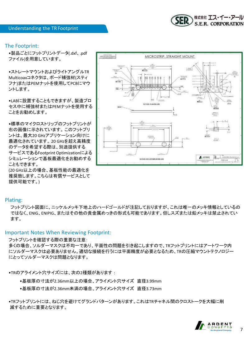
The Footprint:•製品ごとにフットプリントデータ(.dxf、.pdfファイル)を用意しています。
•ストレートマウントおよびライトアングルTR Multicoaxコネクタは、ボード補強材(スティフナ)またはPEMナットを使用してPCBにマウントします。
•LABに設置することもできますが、製造プロセス中に補強材またはPEMナットを使用することをお勧めします。
•標準のマイクロストリップのフットプリントが右の画像に示されています。このフットプリ
ントは、最大20 GHzアプリケーション向けに最適化されています。 20 GHzを超え高精度のデータを希望する際は、別途提供する
サービスであるFootprint Optimizationによるシミュレーションで基板最適化をお勧めする
こともできます。
(20 GHz以上の場合、基板性能の最適化を推奨致します。こちらは有償サービスとして
提供可能です。)
Plating:フットプリント図面に、ニッケルメッキ下地上のハードゴールドが注記しておりますが、これは唯一のメッキ情報としているの
ではなく、ENIG、ENIPIG、またはその他の貴金属めっきの形式も可能であります。但しスズまたは鉛メッキは禁止されています。
Important Notes When Reviewing Footprint:フットプリントを確認する際の重要な注意:
多くの場合、ソルダーマスクは不均一であり、平面性の問題を引き起こしますので、TRフットプリントにはアートワーク内にソルダーマスクは必要ありません。適切な接続を行うには平面精度が必要となるため、TRの圧縮マウントテクノロジーにとってソルダーマスクは問題となります。
•TRのアライメント穴サイズには、次の2種類があります :
•基板厚の寸法が2.36mm以上の場合、アライメント穴サイズ 直径3.99mm•基板厚の寸法が2.36mm未満の場合、アライメント穴サイズ 直径3.73mm
•TRフットプリントには、ねじ穴を避けてグランドパターンがあります。これはTRチャネル間のクロストークを大幅に削減するために重要となります。
Understanding the TR Footprint

8 [email protected] • [email protected] • www.ardentconcepts.com
Terminate-R (TR) Launch Optimization ChecklistCOMPANY NAME: GENERIC COMPANY A
1. What is the maximum operating frequency? 12 GHz
2. What type of signal?Digital ☒ Analog ☒
3. How many channels will the TR Multi-coax cable have? 1 ☐ 4 ☐ 8 ☒ 12 ☐ 16 ☐ 24 ☐
4. What is the pitch of the connector? (NOTE: The standard pitch is 2.54mm)Standard
5. Is the PCB stack-up included? (NOTE: The PCB stack-up must be included to start work on order) YES ☒ NO☐
6. What is the PCB total thickness?See stackup file
7. Is the PCB trace design microstrip or stripline? Microstrip ☒ Stripline☐
8. If the PCB trace design is microstrip, is the transmission line CPWG?CPWG ☐ NON-CPWG ☐
9. What layers are there to be signals launched on? microstrip
10. What is the dielectric constant of the PCB material surrounding the signal layers? Meg 6
11. How many total layers does the PCB have? MS routing – no vias in design
12. If the PCB stack does not specify, indicate reference/ground layer numbers See stackup
13. If the PCB stack does not specify, indicate power layers’ numbers See stackup
14. If the PCB stack does not specify, indicate signal layers’ numbers See stackup
15. Is the TR mounted on Top (Layer 1) or the Bottom of the PCB? Top (Layer 1) ☒ Bottom☐
16. Via drill diameters are .010” (.25mm) as standard. Will these drill diameters be used?If not, what is the desired drill diameter?
10mil17. What is the desired return loss at a given frequency of the optimization?
The default is: [ -20 dB to 20 GHz] and [ -12 dB to 40GHz] Default is o.k.
What’s Provided?
Key Benefits以下の項目を考慮してPCB設計の最適化を行います。・基板材料(誘電率)・層の厚さ・完全なPCBスタックアップ
お客様のPCBボードとTRコネクタの3Dモデルとともに、高度な電磁3Dシミュレーションを使用して、最適化データを提供します。
DescriptionTRシリーズは70 GHzを超える測定が可能な高密度マルチ同軸ケーブル製品です、ソルダーレス接続によるコンプレッションマウントは、業界で唯一のソリューションで
す。
高精度と高性能を実現するために、基板のフットプリント情報を含めTRシリーズの実力を最適化するために奮闘しております。PCBランチコネクタは、TRコネクタから最大のパフォーマンスを引き出すために不可欠です。
Simple ‘OptimizationChecklist’
Example of 3-D EM model created with ANSYS® HFSS
Consult factory forchecklist
Coaxial Launch Optimization
ランチ最適化に含まれる内容:› 寸法の結果
•信号パッド•表層アンチパッド•裏面アンチパッド•グランドビア深さ•狭伝送路 (コネクター下部)
› モデリングの結果•通過特性 (S21)•反射特性 (S11)•タイムドメイン(TDR)
› Sパラメータファイル(.S2P)› フットプリントレビュー› エクセルデータ出力

An Amphenol Company 9
Notes: 1Largely a function of PCB design. 2Measurement includes 3” of cable.3Consult factory for additional cable options.
Footprint Microstrip & Stripline compatible
Electrical Specifications Mechanical Specifications
Frequency Range DC to 70 GHz+ Pitch 2.54 mmReturn Loss1 -18 dB through 70 GHz Cables .047” diameter cables3
Insertion Loss2 -1.5 dB through 40 GHz, -3 dB through 70 GHz Connectors V (1.85 mm)
Crosstalk -70 dB through 70 GHz Cable Length 6”/152 mm, 12”/304 mm, 24”/ 608 mmImpedance1 50 Ω +/- 2.5Ω Insertion Life 1,000+ mating cyclesPhase Matching +/- 2 ps standard Field Replaceable Interface Yes
Notes: 1Largely a function of PCB design. 2Measurement includes 3” of cable.3Consult factory for additional cable options.
Electrical Specifications Mechanical Specifications
Frequency Range DC to 70 GHz+ Pitch 2.54 mmReturn Loss1 -18 dB through 70 GHz Cables .047” diameter cables3
Insertion Loss2 -1.5 dB through 40 GHz, -3 dB through 70 GHz Connectors V (1.85 mm)
Crosstalk -70 dB through 70 GHz Cable Length 6”/152 mm, 12”/304 mm, 24”/ 608 mmImpedance1 50 Ω +/- 2.5Ω Insertion Life 1,000+ mating cyclesPhase Matching +/- 2 ps standard Field Replaceable Interface Yes
Footprint Microstrip & Stripline compatible
TR Multicoax 4x1 (20/40/70 GHz configurations available)
TR Multicoax 8x1 (20/40/70 GHz configurations available)

10 [email protected] • [email protected] • www.ardentconcepts.com
TR Multicoax 12x1 (20/40/70 GHz configurations available)
TR Multicoax 16x2 (20/40/70 GHz configurations available)
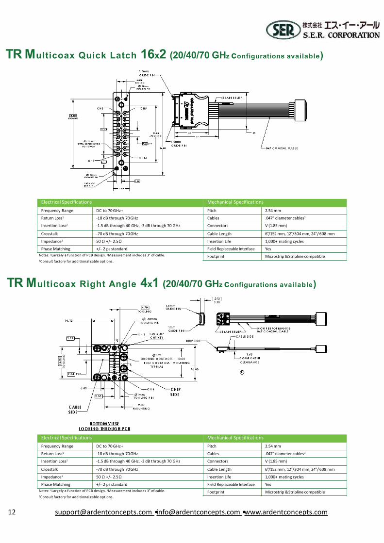
Notes: 1Largely a function of PCB design. 2Measurement includes 3” of cable.3Consult factory for additional cable options.
Electrical Specifications Mechanical SpecificationsFrequency Range DC to 70 GHz+ Pitch 2.54 mm
Return Loss1 -18 dB through 70 GHz Cables .047” diameter cables3
Insertion Loss2 -1.5 dB through 40 GHz, -3 dB through 70 GHz Connectors V (1.85 mm)
Crosstalk -70 dB through 70 GHz Cable Length 6”/152 mm, 12”/304 mm, 24”/ 608 mmImpedance1 50 Ω +/- 2.5Ω Insertion Life 1,000+ mating cycles
Phase Matching +/- 2 ps standard Field Replaceable Interface YesFootprint Microstrip & Stripline compatible
Notes: 1Largely a function of PCB design. 2Measurement includes 3” of cable.3Consult factory for additional cable options.
Electrical Specifications Mechanical SpecificationsFrequency Range DC to 70 GHz+ Pitch 2.54 mm
Return Loss1 -18 dB through 70 GHz Cables .047” diameter cables3
Insertion Loss2 -1.5 dB through 40 GHz, -3 dB through 70 GHz Connectors V (1.85 mm)
Crosstalk -70 dB through 70 GHz Cable Length 6”/152 mm, 12”/304 mm, 24”/ 608 mm
Impedance1 50 Ω +/- 2.5Ω Insertion Life 1,000+ mating cyclesPhase Matching +/- 2 ps standard Field Replaceable Interface Yes
Footprint Microstrip & Stripline compatible

An Amphenol Company 11
Notes: 1Largely a function of PCB design. 2Measurement includes 3” of cable.3Consult factory for additional cable options.
Electrical Specifications Mechanical Specifications
Frequency Range DC to 70 GHz+ Pitch 2.54 mmReturn Loss1 -18 dB through 70 GHz Cables .047” diameter cables3
Insertion Loss2 -1.5 dB through 40 GHz, -3 dB through 70 GHz Connectors V (1.85 mm)
Crosstalk -70 dB through 70 GHz Cable Length 6”/152 mm, 12”/304 mm, 24”/ 608 mmImpedance1 50 Ω +/- 2.5Ω Insertion Life 1,000+ mating cyclesPhase Matching +/- 2 ps standard Field Replaceable Interface Yes
Footprint Microstrip & Stripline compatible
3Consult factory for additional cable options.
Electrical Specifications Mechanical Specifications
Frequency Range DC to 70 GHz+ Pitch 2.54 mmReturn Loss1 -18 dB through 70 GHz Cables .047” diameter cables3
Insertion Loss2 -1.5 dB through 40 GHz, -3 dB through 70 GHz Connectors V (1.85 mm)
Crosstalk -70 dB through 70 GHz Cable Length 6”/152 mm, 12”/304 mm, 24”/ 608 mmImpedance1 50 Ω +/- 2.5Ω Insertion Life 1,000+ mating cyclesPhase Matching +/- 2 ps standard Field Replaceable Interface Yes
Notes: 1Largely a function of PCB design. 2Measurement includes 3” of cable. Footprint Microstrip & Stripline compatible
TR Multicoax 24x2 (20/40/70 GHz configurations available)
TR Multicoax Quicklatch 8x1 (20/40/70 GHz configurations available)
12 [email protected] • [email protected] • www.ardentconcepts.com
3Consult factory for additional cable options.
Electrical Specifications Mechanical SpecificationsFrequency Range DC to 70 GHz+ Pitch 2.54 mmReturn Loss1 -18 dB through 70 GHz Cables .047” diameter cables3
Insertion Loss2 -1.5 dB through 40 GHz, -3 dB through 70 GHz Connectors V (1.85 mm)
Crosstalk -70 dB through 70 GHz Cable Length 6”/152 mm, 12”/304 mm, 24”/ 608 mm
Impedance1 50 Ω +/- 2.5Ω Insertion Life 1,000+ mating cyclesPhase Matching +/- 2 ps standard Field Replaceable Interface Yes
Notes: 1Largely a function of PCB design. 2Measurement includes 3” of cable. Footprint Microstrip & Stripline compatible
TR Multicoax Quick Latch 16x2 (20/40/70 GHz configurations available)
TR Multicoax Right Angle 4x1 (20/40/70 GHz configurations available)

An Amphenol Company 13
3Consult factory for additional cable options.
Electrical Specifications Mechanical Specifications
Frequency Range DC to 70 GHz+ Pitch 2.54 mmReturn Loss1 -18 dB through 70 GHz Cables .047” diameter cables3
Insertion Loss2 -1.5 dB through 40 GHz, -3 dB through 70 GHz Connectors V (1.85 mm)
Crosstalk -70 dB through 70 GHz Cable Length 6”/152 mm, 12”/304 mm, 24”/ 608 mmImpedance1 50 Ω +/- 2.5Ω Insertion Life 1,000+ mating cyclesPhase Matching +/- 2 ps standard Field Replaceable Interface Yes
Notes: 1Largely a function of PCB design. 2Measurement includes 3” of cable. Footprint Microstrip & Stripline compatible
Electrical Specifications Mechanical SpecificationsFrequency Range DC to 70 GHz+ Pitch 2.54 mmReturn Loss1 -18 dB through 70 GHz Cables .047” diameter cables3
Insertion Loss2 -1.5 dB through 40 GHz, -3 dB through 70 GHz Connectors V (1.85 mm)Crosstalk -70 dB through 70 GHz Cable Length 6”/152 mm, 12”/304 mm, 24”/ 608 mmImpedance1 50 Ω +/- 2.5Ω Insertion Life 1,000+ mating cyclesPhase Matching +/- 2 ps standard Field Replaceable Interface Yes
Notes: 1Largely a function of PCB design. 2Measurement includes 3” of cable.3Consult factory for additional cable options.
Footprint Microstrip & Stripline compatible
TR Multicoax Right Angle 8x1 (20/40/70 GHz configurations available)
TR Multicoax Right Angle 12x1 (20/40/70 GHz configurations available)

14 [email protected] • [email protected] • www.ardentconcepts.com
3Consult factory for additional cable options.
Electrical Specifications Mechanical SpecificationsFrequency Range DC to 70 GHz+ Pitch 2.54 mm
Return Loss1 -18 dB through 70 GHz Cables .047” diameter cables3
Insertion Loss2 -1.5 dB through 40 GHz, -3 dB through 70 GHz Connectors V (1.85 mm)
Crosstalk -70 dB through 70 GHz Cable Length 6”/152 mm, 12”/304 mm, 24”/ 608 mm
Impedance1 50 Ω +/- 2.5Ω Insertion Life 1,000+ mating cyclesPhase Matching +/- 2 ps standard Field Replaceable Interface Yes
Notes: 1Largely a function of PCB design. 2Measurement includes 3” of cable. Footprint Microstrip & Stripline compatible
TR Multicoax Right Angle 16x2 (20/40/70 GHz configurations available)
TR Multicoax Leapfrog 8x1 (20/40/70 GHz configurations available)

An Amphenol Company 15
Notes: 1Largely a function of PCB design. 2Measurement includes 3” of cable.3Consult factory for additional cable options.
Electrical Specifications Mechanical Specifications
Frequency Range DC to 70 GHz+ Pitch 2.54 mmReturn Loss1 -18 dB through 70 GHz Cables .047” diameter cables3
Insertion Loss2 -1.5 dB through 40 GHz, -3 dB through 70 GHz Connectors V (1.85 mm)
Crosstalk -70 dB through 70 GHz Cable Length 6”/152 mm, 12”/304 mm, 24”/ 608 mmImpedance1 50 Ω +/- 2.5Ω Insertion Life 1,000+ mating cyclesPhase Matching +/- 2 ps standard Field Replaceable Interface Yes
Footprint Microstrip & Stripline compatible
Electrical Specifications Mechanical SpecificationsFrequency Range DC to 70 GHz+ Pitch 3.60 mmReturn Loss1 Less than -15 dB to 70GHz Cables .086” diameter cables3
Insertion Loss2 -1.5 dB through 40 GHz, -3 dB through 70 GHz Connectors SMK (2.92 mm), or V (1.85mm)Crosstalk -70 dB through 70 GHz Cable Length 6”/152 mm, 12”/304 mm, 24”/ 608 mmImpedance1 50 Ω +/- 2.5Ω Insertion Life 1,000+ mating cyclesPhase Matching +/- 2 ps standard Field Replaceable Interface Yes
Notes: 1Largely a function of PCB design. 2Measurement includes 3” of cable.3Consult factory for additional cable options.
Footprint Microstrip & Stripline compatible
TR to TR
TR Multicoax Equal Trace

16 [email protected] • [email protected] • www.ardentconcepts.com
Notes: 1Largely a function of PCB design. 2Measurement includes 3” of cable.3Consult factory for additional cable options.
Electrical Specifications Mechanical SpecificationsFrequency Range DC to 70 GHz+ Pitch 2.54 mm
Return Loss1 -18 dB through 70 GHz CablesInsertion Loss2 -1.5 dB through 40 GHz, -3 dB through 70 GHz Connectors
Crosstalk -70 dB through 70 GHz Cable LengthImpedance1 50 Ω +/- 2.5Ω Insertion Life 1,000+ mating cycles
Phase Matching +/- 2 ps standard Field Replaceable Interface YesFootprint Microstrip & Stripline compatible
Notes: 1Largely a function of PCB design. 2Measurement includes 3” of cable.3Consult factory for additional cable options.
Electrical Specifications Mechanical SpecificationsFrequency Range 70 - 90 GHz+ Pitch 2.54 mmReturn Loss1 -10 dB or better from 71 GHz to 90 GHz Cables SemirigidInsertion Loss2 No resonance out to 90GHz Connectors 1.0 mm female
Crosstalk -30 dB from 71 GHzto 86 GHz Cable Length 3”/76mmImpedance1 50 Ω +/- 2.5Ω Insertion Life 1,000+ mating cycles
Phase Matching +/- 2 ps standard Field Replaceable Interface YesFootprint Microstrip & Stripline compatible
TR Loopback
TR90 (90GHz) Preliminary

An Amphenol Company 17
Key Benefits
•防漏洩設計 (Max leak rate 2.00E-09 LTorr)•さまざまな同軸ケーブル材料が利用可能 (Flexible, CuNi, NbTi,BeCu)•高密度のフォームファクタ (160+ channels in standard ISO disc)•複数の高速レーンを簡単に接続/脱着
Applications
50Ωハーメチックフィードスルーは、次の用途に最適です。
› 希釈冷蔵庫/極低温デバイス› 量子コンピュータ› 真空チャンバー›RF信号のシールド内伝送時
Description
ハーメチックフィードスルーで嵌合できるTR Multicoaxシリーズコネクタは、高速信号の伝送に気密性が不可欠となる場面では最適なアプリ
ケーションです。これらの場面では、片側のTRコネクタ端でハーメチックフィードにストレートで結合され、2つのチャンバー間のインピーダンスが整合した50Ωチャネルを保証します。フィードスルーは、真空の内側から止まり穴にねじでフランジ(ISOディスクなど)に固定されています。ハーメチックフィードスルーはエポキシポッティングを使用して完
全に密閉されます。
Ten (10) 16-channel Hermetic Feedthroughs
Highly Scalable
Standard TR Multicoax
TR Multicoax with CuNi
Cables
50Ω HermeticFeedthrough
Potting for leak-proof seal
17An AmphenolCompany
TR Muliticoax Series 50ΩHermetic feed through

18 [email protected] • [email protected] • www.ardentconcepts.com
TR Multicoax Evaluation Kit
Introduction:70 GHzを超える速度で処理できる高密度多同軸ケーブルTRシリーズは基板へコンプレッションマウントで搭載できる唯一のコネクタ製品です。お客様自身でデバイスを評価したいと考える方のために、TR20、TR40、およびTR70 GHz シリーズの製品を評価できるEvaluation Kitを用意しています。
Contents:検証用キットには、TR製品を評価するために必要となるコンポーネントが付属されています。O TR70 +本体: 8チャンネルのストレートマウントタイプの6インチ同軸ケーブルと1.85 mmコネクタO評価ボード:評価ボードは、ロジャース製のFR4+補強材を使用しております。<基板仕様>
・表層厚(Cu) : 0.0432 mm、ENIGメッキ・ロジャース3003 誘電層厚:0.254 mm;誘電率(Dk) = 3.075; 誘電正接(tan) = 0.0065
・グランド層厚:0.018 mm・FR4補強用のフローティングソリッドボトムメタル
An Amphenol Company 19
Frequently Asked Questions
1. TR Multi-Coaxは今までになかった製品のように見えますが、正確にはどのような製品ですか?
• TRシリーズは70 GHzを超える測定が可能な高密度マルチ同軸ケーブル製品です、ソルダーレス接続によるコンプレッションマウントは、業界で唯一のソリューションです。
• TRシリーズマルチ同軸ケーブルは、独自のコンパクトなインターフェース設計により基板の面積を大幅に節約します。
• ご希望の各種同軸コネクタに接続することが可能です。• 基板上のフットプリントへコンプレッションマウントによる接続スタイルです。つまりソルダーレスマウントにより、基板にはんだ付けする必要がありません。
2.アプリケーションに適した型番を選択するにはどうすればよいですか?
• 型番選択は非常にシンプルです• TR製品は周波数別にグループ分けしています。• 大きく分けてTR20、TR40、TR70 の3種類を用意しています。
• 20、40,、70は最大周波数範囲(GHz)を示します。• 周波数に基づいて同軸ケーブルアセンブリを選択したら、取り付けスタイルを選択します。
• コストメリットがある製品はストレートマウントです、基板への固定はネジを使用して簡単に取り付けられるように設計されており、基板の面積を節約できます。
• ネジによる固定しないスタイルでは、クイックラッチがあります。これにより、簡単なプッシュオンで製品を取り付けることができます。クイックラッチは製品を基板に固定するためのネジは必要ありません。
• 基板上のスペースが制限されている場合、ライトアングルの使用をお薦めします。
• 標準製品にない同軸ケーブルの長さと必要なチャネル数のリクエストには、カスタムメイドで柔軟性に対応します。
• ケーブルと同軸コネクタの接続については周波数に適したコネクタにしております。上位、他コネクタが必要で有ればご用命下さい。念のためコネクタのオス/メスの選択についてはご確認後にご用命ください。
3.同軸ケーブルの最大長または最小長はありますか?• コストメリットがある製品については、21ページの表にリストされている長さから選択することをお勧めします。
• ただし、3インチから36インチまでのカスタムアプリケーションにも対応できます。カスタムアプリケーションについてはお問い合わせください。
4.製品はどんな検査を受けますか?• すべての製品は、組み立ての後の段階で目視検査をおこなっております。
• TR製品はメカニカルテストで、コンプレッションが確実に行われることを確認します。マウントテクノロジーが正しく機能する基本となります。
• 最終工程では、すべての製品の導通がチェックされ、電気接続が確実に行われたことを確認しています。
5. TR製品の位相は一致していますか?• すべてのTR製品は、+/- 2p/s以下の位相一致であることが基本的に保証されています。
• 厳しい相対位相整合許容値を必要とする場合は、検討しますのでお問い合わせください。
6. TR 製品の補足データを提供していますか?• 標準のTR 製品にはembedded dataとして S2p file を提供します。
7.TR 製品のフットプリントはどこにありますか?• フットプリントが見つからな場合は、お問い合わせください。
8. PCBに対処する必要がある特別な考慮事項はありますか?• シミュレーションの際はPCBフットプリントで最適化を実行することを強くお勧めします。
• お客様独自のPCBスタックアップに基づいてPCBフットプリントを最適化するサービスを提供しています。
• 取り組みの一環として、TR 製品フットプリントに正しく実装されていることを確認するために、すべてのお客様のPCBのモデルを確認することを推奨いたします。
9.製品保証はありますか?• 購入して頂いたTR製品は最長で1年間無償で修理します。
10. TR製品の納期やお見積もりはどのくらいで回答がありますか?
• 標準TR製品の場合、お客様のリクエストを受け取ったその日に、見積を提出できます。
• 標準TR製品の場合、通常、受注後から6週間以内に配送できます。
11. フットプリント図面には「TRフットプリント領域にソルダーレジストがないこと」と書かれていますが、これは厳密な要件ですか?、その理由は何ですか?
• PCBに接触するTRの表面は、金属表面に強く押し当てる必要があります。
• ソルダーレジストがフットプリントに適用されている場合、ソルダーレジストが上部のパターン層よりも厚くなる場合があります。
• この結果、ソルダーレジストがピンテクノロジーの妨げとなり、シグナルインテグリティが低下します。
12. さらに質問がありますか?• ウェブサイトwww.ardentconcepts.comにアクセスするか、日本代理店のエス・イー・アール [email protected]にメールを送信してください。
FAQ

20 [email protected] • [email protected] • www.ardentconcepts.com
FAQ Corresponding Tables
RC04-04
RC SpringprobeTM
RC05-01
RC SpringprobeTM
RC08-02
RC SpringprobeTM
RC10-07
RC SpringprobeTM
RC10-04
RC SpringprobeTM
RC12-06
RC SpringprobeTM
CR08-062
RC Connect-RTM
Contact MaterialGold Plated Beryllium
CopperGold Plated Beryllium
CopperGold Plated Beryllium
CopperGold Plated Beryllium
CopperGold Plated Beryllium
CopperGold Plated Beryllium
CopperGold Plated Beryllium
CopperMated Height (in/mm) 0.030/0.76 0.030/0.76 0.045/1.14 0.055/1.40 0.085/2.16 0.090/2.29 .062/1.57
Pitch (in/mm) 0.0157/0.40 0.0197/0.50 0.0315/0.80 0.0394/1.00 0.0394/1.00 0.0500/1.27 0.0315/0.80Compression Force/Contact (grams +/-20%) 20 20 20 24 22 34 45
Compression Range (in/mm) 0.006/0.15 0.006/0.15 0.009/0.23 0.010/0.25 0.015/0.38 0.015/0.38 0.010/0.25Contact Resistance (mΩ) 60 45 60 50 66 65 <50
Self Inductance (nH) ~.50 0.45 0.73 0.92 1.35 ~1.50 0.61
High Freq Capacity (-1 dB point, GHz) ~20 25 20 37 11 ~20 40 (@1mm Pitch)
Characteristic Impedance at Native Pitch (Ohms) 56 65 61 73 57 (@1mm Pitch)
Durability (cycles)* 10,000 10,000 10,000 10,000 10,000 10,000 1000+
Current Carrying Capacity (single contact at 30C temp offset, Amps) ~1 ~1 1.8 ~4 3.3 3.55 ~2
TR20 – SM – 4X1 – 2.54 – 06 AF FTR 20 Mounting Option # of channels (FormFactor) Pitch
(mm)Cable Length & Connector Type
Straight Mount (SM) 4 (4X1), 8 (8X1), 12 (12X1),162.54mm
03”(03), 6”(06), 12”(12), 24” SMA Female (AF),(16X2), 24 (24X2) (24) SMA Male (AM)
Quick Latch (QL) 8 (8X1), 16 (16X2) 2.54mm03”(03), 6”(06), 12”(12), 24” SMA Female (AF),(24) SMA Male (AM)
Leap Frog (LF) 8 (8x1), 12 (12x1) 2.54mm 03”(03), 6”(06), 12”(12), 24” SMA Female (AF),(24) SMA Male (AM)
Right Angle (RA) 4 (4X1), 8 (8X1), 12 (12X1),162.54mm
03”(03), 6”(06), 12”(12), 24” SMA Female (AF),(16x2) (24) SMA Male (AM)
TR 40 Mounting Option # of channels (FormFactor) Pitch (mm) Cable Length Connector Type
Straight Mount (SM) 4 (4X1), 8 (8X1), 12 (12X1),16 2.54mm 03”(03), 6”(06), 12”(12), 24”SMK 2.92 mm Female (KF), SMK 2.92 mm Male (KM)(16X2), 24 (24X2) (24)
Quick Latch (QL) 8 (8X1), 16 (16X2) 2.54mm 03”(03), 6”(06), 12”(12), 24” SMK 2.92 mm Female (KF), SMK 2.92 mm Male (KM)(24)
Leap Frog (LF) 8 (8x1), 12 (12x1) 2.54mm 03”(03), 6”(06), 12”(12), 24”SMK 2.92 mm Female (KF), SMK 2.92 mm Male (KM)(24)
Right Angle (RA) 4 (4X1), 8 (8X1), 12 (12X1),16 2.54mm 03”(03), 6”(06), 12”(12), 24”SMK 2.92 mm Female (KF), SMK 2.92 mm Male (KM)(16x2) (24)
TR 70 Mounting Option # of channels (FormFactor) Pitch (mm) Cable Length Connector Type
Straight Mount (SM) 4 (4X1), 8 (8X1), 12 (12X1),16(16X2), 24 (24X2) 2.54mm
03”(03), 6”(06), 12”(12), 24” V 1.85 mm Female (VF),(24) V 1.85 mm Male (VM)
Quick Latch (QL) 8 (8X1), 16 (16X2) 2.54mm03”(03), 6”(06), 12”(12), 24” V 1.85 mm Female (VF),(24) V 1.85 mm Male (VM)
Leap Frog (LF) 8 (8x1), 12 (12x1) 2.54mm03”(03), 6”(06), 12”(12), 24” V 1.85 mm Female (VF),(24) V 1.85 mm Male (VM)
Right Angle (RA)4 (4X1), 8 (8X1), 12 (12X1),16
2.54mm03”(03), 6”(06), 12”(12), 24” V 1.85 mm Female (VF),
(16x2) (24) V 1.85 mm Male (VM)TREqual Trace Mounting Option
Straight Mount (SM)
# of channels (FormFactor)
16 (16x1)
Pitch (mm)
3.6 mm
Cable Length
6”(06), 12”(12), 24”(24)
Connector Type
V 1.85 mm Female(VF), V 1.85 mm Male (VM)

An Amphenol Company 21
Benefits and SI Measurements
TR20™ - 面倒な表面実装コネクタに代わる、低損失、高品質、コスト削減の代替
TR40™ -業界で実績のある製品では最も信頼性が高く、高周波、省スペースの最先端アプリケーション
TR70™ -最高のパフォーマンスで高周波数アプリケーションに最適
Signal Integrity Data

22 [email protected] • [email protected] • www.ardentconcepts.com
Repeatability
TR製品は1,000サイクルにわたる再現性を実証しており、評価データを用意しています。
56ch(14x4=56ch)で測定した結果、すべての伝送ラインでは同じ耐久結果となりました。
1,000サイクルにわたる単一チャネルの再現性0、50、100、500、および1000サイクル毎に測定
De-Embedded Interface Only

An Amphenol Company 23
More Information
Phone:03-5796-0330
E-mail: [email protected]: https://www.ser.co.jp/
Additional ResourcesAsk about our Application Notes and CaseStudies
ケーススタディ、アプリケーションノート、ビデオデモンストレー
ション、ウェビナーなどを含むその他のリソースについては、弊
社のサポートチームに連絡するか、当社のWebサイト(www.ardentconcepts.com)のリソースエリアにアクセスしてください。

24 [email protected] • [email protected] • www.ardentconcepts.com
Ordering Information
xial Connector• DC 70GHzの優れた信号特性• 再利用が可能ですので、プログラム全体のコスト低減が可能• 高信頼性、狭ピッチですので、基板面積の省スペース化に有効• 迅速な基板接続、ネジ止め不要で、工具不要
SK SeriesTM - High Speed | Compression Mount Sockets
•低損失の高性能デバイスに適した40GHz帯域のソリューションを提供致します。
• 70 x 70 mmパッケージサイズまで対応可能•拡張可能なリッド、ベース設計となっておりますので、オプションでOEMデザインが可能
•コンプレッションマウント、ソルダーレスコンタクト
nectors & Interposers
• 32 Gbps帯域• 0.4㎜ピッチまでの配列可能•コンプレッションマウント、ソルダーレスコンタクト• 垂直なインターフェースで、 基板のオフセットが不要• 耐衝撃、耐振動に優れ、広い温度環境に適応