Embed Size (px)
Citation preview
10 YearWARRANTY
www.erlphase.com
High Speed Tripping Relay TR
Description Features
Figure 1: High Speed Tripping Relay - TR
• High speed, positive action• Robust design for long, reliable service life• Supplied in Epsilon draw-out type case• Can be supplied both in E2 and E4 casing
Type TR high speed tripping relays are a range of voltage operated, multi-contact, attracted-armature relays, complying with the appropriate requirements of IEC 60255. A wide range of models is available to meet the requirements of the electrical power sector.
The relays are identified by the product designation 'TR' followed by a series of numbers and letters which define important relay features.
Low Burden, TR1 SeriesType TR1 relays are suitable for application for tripping and auxiliary duties where immunity to capacitance discharge is not required. These relays are not intended for use with current operated series flag relays.
High Burden, TR2 SeriesHigh burden relays have immunity to capacitance discharge currents. They are also suitable for certain applications where they are remote from the initiation signal.
A high burden also permits reliable operation of current operated series repeat relays.
Standard RelaysType First Digit
(Type of Burden)Second Digit
(Contact Reset)Third Digit
(Operating Coil Cut-off)
No. of Contacts Case Size
TR112 Low (1) Self (1) Economy (2) 11 E4
TR121 Low Hand (2) Instantaneous (1) 11 or 22 E2 / E4 *
TR212 High (2) Self Economy 10 or 20 E4
TR221 High Hand Instantaneous 11 or 22 E2 / E4 *
TR231 High Electrical (3) Instantaneous 10 or 20 E2 / E4 *
TR241 High Hand & Electrical (4) Instantaneous 10 or 20 E2 / E4 *
www.erlphase.com
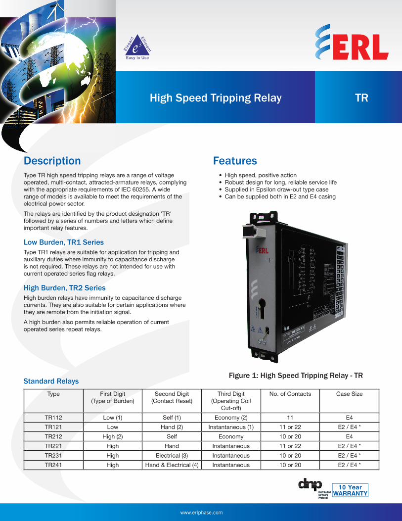
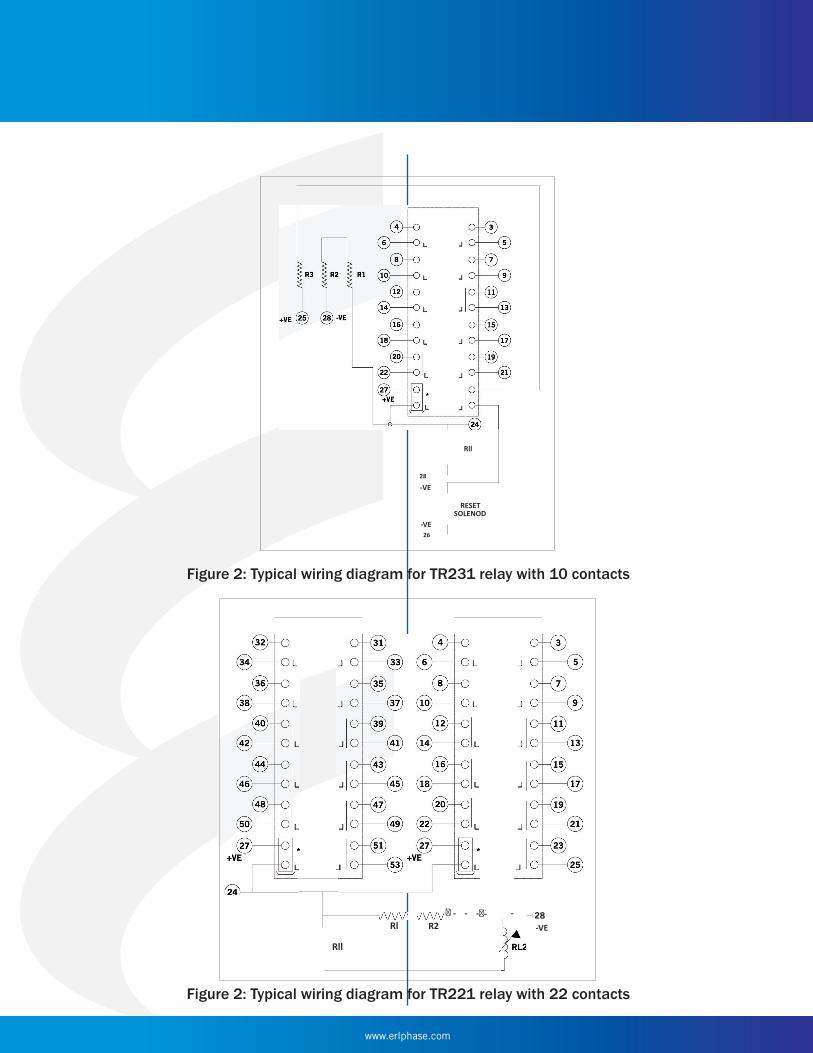
Figure 2: Typical wiring diagram for TR231 relay with 10 contacts
Rll
28
-VE
RESET SOLENOD
-VE 26
Rl R2 -VE� - - -�- -
Rll
Figure 2: Typical wiring diagram for TR221 relay with 22 contacts
www.erlphase.com
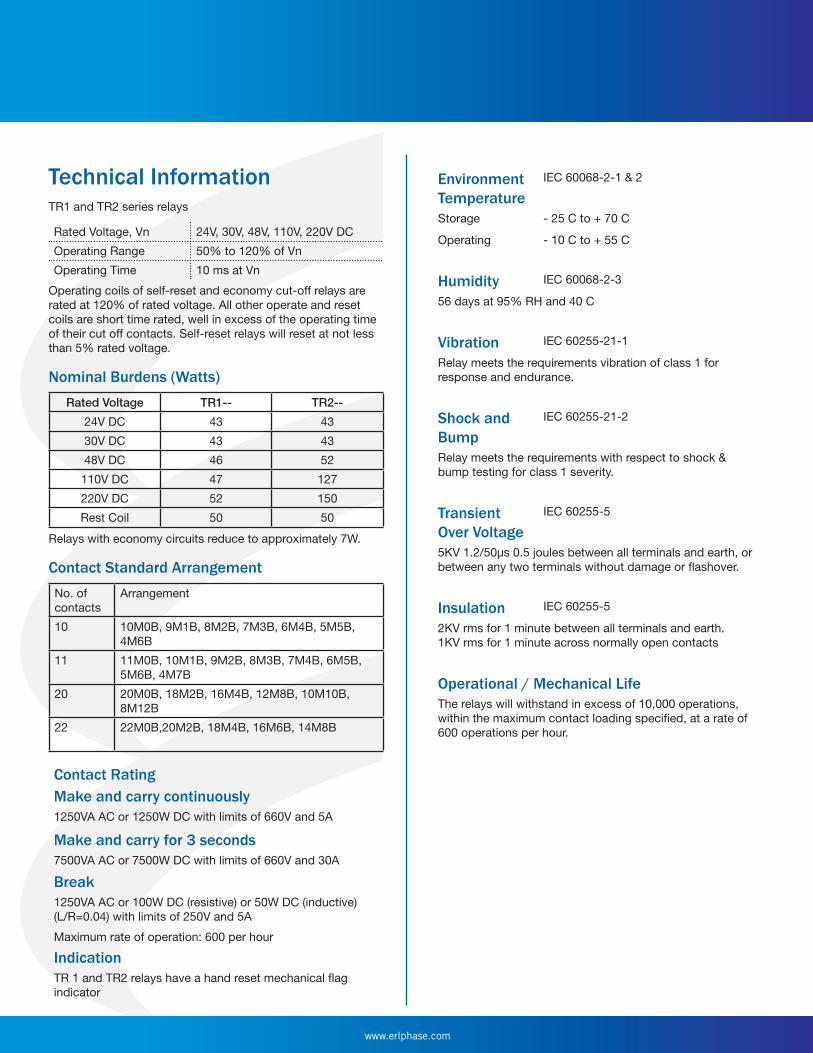
Technical InformationTR1 and TR2 series relays
Rated Voltage, Vn 24V, 30V, 48V, 110V, 220V DC
Operating Range 50% to 120% of Vn
Operating Time 10 ms at Vn
Operating coils of self-reset and economy cut-off relays are rated at 120% of rated voltage. All other operate and reset coils are short time rated, well in excess of the operating time of their cut off contacts. Self-reset relays will reset at not less than 5% rated voltage.
Nominal Burdens (Watts)Rated Voltage TR1-- TR2--
24V DC 43 43
30V DC 43 43
48V DC 46 52
110V DC 47 127
220V DC 52 150
Rest Coil 50 50
Relays with economy circuits reduce to approximately 7W.
Contact Standard ArrangementNo. of contacts
Arrangement
10 10M0B, 9M1B, 8M2B, 7M3B, 6M4B, 5M5B, 4M6B
11 11M0B, 10M1B, 9M2B, 8M3B, 7M4B, 6M5B, 5M6B, 4M7B
20 20M0B, 18M2B, 16M4B, 12M8B, 10M10B, 8M12B
22 22M0B,20M2B, 18M4B, 16M6B, 14M8B
Contact RatingMake and carry continuously1250VA AC or 1250W DC with limits of 660V and 5A
Make and carry for 3 seconds7500VA AC or 7500W DC with limits of 660V and 30A
Break1250VA AC or 100W DC (resistive) or 50W DC (inductive) (L/R=0.04) with limits of 250V and 5A
Maximum rate of operation: 600 per hour
IndicationTR 1 and TR2 relays have a hand reset mechanical flag indicator
Environment Temperature
IEC 60068-2-1 & 2
Storage - 25 C to + 70 C
Operating - 10 C to + 55 C
Humidity IEC 60068-2-3
56 days at 95% RH and 40 C
Vibration IEC 60255-21-1
Relay meets the requirements vibration of class 1 for response and endurance.
Shock and Bump
IEC 60255-21-2
Relay meets the requirements with respect to shock & bump testing for class 1 severity.
Transient Over Voltage
IEC 60255-5
5KV 1.2/50µs 0.5 joules between all terminals and earth, or between any two terminals without damage or flashover.
Insulation IEC 60255-5
2KV rms for 1 minute between all terminals and earth. 1KV rms for 1 minute across normally open contacts
Operational / Mechanical LifeThe relays will withstand in excess of 10,000 operations, within the maximum contact loading specified, at a rate of 600 operations per hour.
www.erlphase.com
ERLPhase Power TechnologiesTel: 204-477-0591Email: [email protected] specifications and product information contained in this document are subject to change without notice. In case of inconsistencies between documents, the version at www.erlphase.com will be considered correct. (D04253)
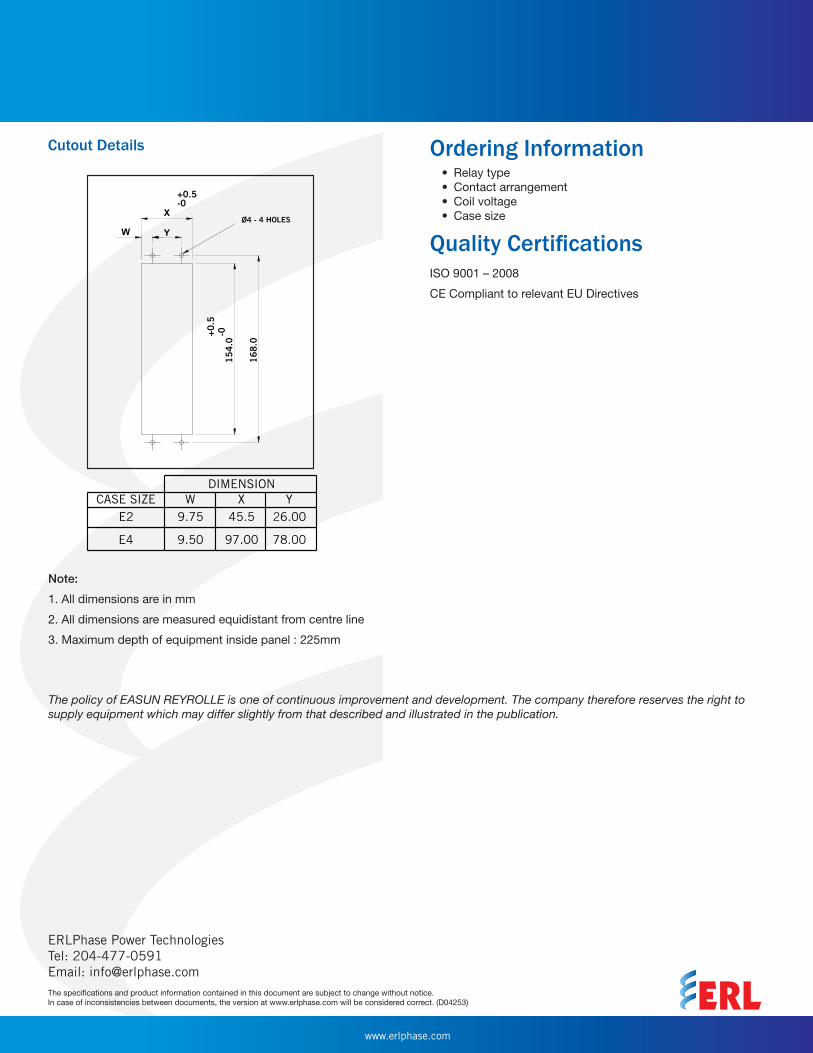
Cutout Details Ordering Information
The policy of EASUN REYROLLE is one of continuous improvement and development. The company therefore reserves the right to supply equipment which may differ slightly from that described and illustrated in the publication.
Note:
1. All dimensions are in mm
2. All dimensions are measured equidistant from centre line
3. Maximum depth of equipment inside panel : 225mm
• Relay type• Contact arrangement• Coil voltage• Case size
Quality CertificationsISO 9001 – 2008
CE Compliant to relevant EU Directives


![GROUND OVER VOLTAGE RELAY[64] · The relay is used in non-grounded power system of distribution lines of power station for the purpose of tripping circuit breaker through the use](https://img.pdfslide.us/doc/110x75/6016ce80e4e4bb557426a4d0/ground-over-voltage-relay64-the-relay-is-used-in-non-grounded-power-system-of.jpg)