Embed Size (px)
Citation preview

ETSI TR 101 695 V3.1.1 (1999-10)Technical Report
Integrated Services Digital Network (ISDN);Universal Mobile Telecommunications System (UMTS);
ISDN-UMTS Framework

ETSI
ETSI TR 101 695 V3.1.1 (1999-10)2
ReferenceDTR/NA-061301 (fp001ics.PDF)
KeywordsUMTS, mobility, ISDN, architecture
ETSI
Postal addressF-06921 Sophia Antipolis Cedex - FRANCE
Office address650 Route des Lucioles - Sophia Antipolis
Valbonne - FRANCETel.: +33 4 92 94 42 00 Fax: +33 4 93 65 47 16
Siret N° 348 623 562 00017 - NAF 742 CAssociation à but non lucratif enregistrée à laSous-Préfecture de Grasse (06) N° 7803/88
Individual copies of this ETSI deliverablecan be downloaded from
http://www.etsi.orgIf you find errors in the present document, send your
comment to: [email protected]
Copyright Notification
No part may be reproduced except as authorized by written permission.The copyright and the foregoing restriction extend to reproduction in all media.
© European Telecommunications Standards Institute 1999.All rights reserved.

ETSI
ETSI TR 101 695 V3.1.1 (1999-10)3
Contents
Intellectual Property Rights ............................................................................................................................... 5
Foreword ............................................................................................................................................................ 5
1 Scope........................................................................................................................................................ 6
2 References................................................................................................................................................ 6
3 Abbreviations........................................................................................................................................... 7
4 Introduction to ISDN-UMTS Framework ............................................................................................... 9
5 Overall requirements ............................................................................................................................. 115.1 Service requirements........................................................................................................................................ 115.2 System and business requirements ................................................................................................................... 115.3 Architecture and protocol requirements........................................................................................................... 125.4 Network infrastructures.................................................................................................................................... 125.5 Roaming and handover between mobile systems............................................................................................. 135.6 UMTS system capabilities ............................................................................................................................... 15
6 Service perspectives............................................................................................................................... 166.1 UMTS role models .......................................................................................................................................... 166.1.1 Home Mobility Provider ............................................................................................................................ 166.1.2 Serving Network Mobility Provider ........................................................................................................... 166.1.3 Service Provider......................................................................................................................................... 166.1.4 Roaming Broker ......................................................................................................................................... 176.1.5 Serving Network ........................................................................................................................................ 176.2 Generic VHE scenarios.................................................................................................................................... 17
7 Identification of the ISDN-UMTS Sub-Systems ...................................................................................197.1 UMTS Domains in SMG12 ............................................................................................................................. 20
8 Serving Network Domain ...................................................................................................................... 228.1 Transport network............................................................................................................................................ 238.1.1 Transport of services .................................................................................................................................. 238.1.1.1 Multimedia applications ....................................................................................................................... 238.1.1.2 Internet services.................................................................................................................................... 248.1.1.3 Multimedia services.............................................................................................................................. 248.1.1.4 Connection types .................................................................................................................................. 258.1.1.5 Resource allocation............................................................................................................................... 258.1.1.6 Transport over Radio............................................................................................................................ 268.1.2 Circuit switched transport networks ........................................................................................................... 268.2 Control network ............................................................................................................................................... 288.2.1 UMTS procedures ...................................................................................................................................... 288.2.1.1 Location management procedures ........................................................................................................ 298.2.1.1.1 Considerations on location management......................................................................................... 298.2.1.1.2 Introduction to the procedures ........................................................................................................ 308.2.1.1.3 Information model for location management .................................................................................. 308.2.1.2 Attach/Detach procedures..................................................................................................................... 328.2.1.3 Handover control .................................................................................................................................. 338.2.1.3.1 Functional and procedural requirements for handover.................................................................... 338.2.2 Functional model for UMTS ...................................................................................................................... 358.2.2.1 Requirements for the UMTS functional model..................................................................................... 358.2.2.2 The IMT2000 functional models .......................................................................................................... 368.2.3 IN enhancements to support UMTS........................................................................................................... 388.2.3.1 Impact of handover on IN..................................................................................................................... 388.2.3.2 Triggering of IN control functions for handover .................................................................................. 388.2.3.3 Execution of intra-switch handover ...................................................................................................... 398.2.3.4 Execution of inter-switch handover ...................................................................................................... 438.2.3.5 State modelling for handover................................................................................................................ 43

ETSI
ETSI TR 101 695 V3.1.1 (1999-10)4
8.2.3.5.1 Introduction..................................................................................................................................... 438.2.3.5.2 Evolution of IN for the integration with B-ISDN............................................................................ 438.2.3.5.3 Handover State Model .................................................................................................................... 448.2.3.5.4 Single Bearer State Model .............................................................................................................. 458.2.3.6 Handover of call control and service control........................................................................................ 46
9 Application Domain............................................................................................................................... 50
Annex A (normative): Role model related material 51
A.1 UMTS role model (UMTS 22.01) ......................................................................................................... 51A.1.1 Overview of the UMTS role model in UMTS 22.01 ....................................................................................... 51A.1.2 Description of roles in UMTS 22.01................................................................................................................ 51A.1.3 Relationships in the provision and use of UMTS services............................................................................... 52A.1.4 Hybrid role models .......................................................................................................................................... 52A.1.5 Observations .................................................................................................................................................... 55
A.2 VHE scenarios based on UMTS 22.01.................................................................................................. 56A.2.1 Subscriber registration procedure in the case where the Home Mobility function resides in the Service
Provider role .................................................................................................................................................... 56A.2.1.1 Subscriber registration without Roaming Broker (RB) involved ............................................................... 56A.2.1.2 Subscriber registration involving a Roaming Broker (RB) ........................................................................ 58A.2.2 Subscriber registration procedure in the case where the Home Mobility function resides in the Network
Operator role.................................................................................................................................................... 60A.2.2.1 Subscriber registration without Roaming Broker (RB) involved ............................................................... 60A.2.2.2 Subscriber registration involving a Roaming Broker (RB) ........................................................................ 62
A.3 VHE scenarios based on GSM MoU TG.25.......................................................................................... 65A.3.1 Location registration procedure ....................................................................................................................... 65A.3.1.1 Location registration involving a SNMP and RB....................................................................................... 65A.3.1.1.1 Explanation of Location Registration involving an SNMP and RB...................................................... 67A.3.1.2 Location Registration (simple case) ........................................................................................................... 67A.3.1.2.1 Explanation of Location Registration (simple case) ............................................................................. 70A.3.1.3 Combining roles ......................................................................................................................................... 70A.3.2 Subscriber Registration procedure................................................................................................................... 72A.3.2.1 Subscriber Registration involving a SNMP and RB................................................................................... 72A.3.2.1.1 Explanation of Subscriber Registration involving an SNMP and RB................................................... 74A.3.2.2 Subscriber Registration (Simple Case)....................................................................................................... 74A.3.2.2.1 Explanation of Subscriber Registration (simple case) .......................................................................... 76A.3.2.3 Combining roles ......................................................................................................................................... 76
A.4 Service provision scenarios based on GSM MoU TG.25...................................................................... 78A.4.1 The roaming role model................................................................................................................................... 78A.4.2 Requirements and assumptions ........................................................................................................................ 78A.4.3 Generic information flows ............................................................................................................................... 78A.4.3.1 Information flows for incoming call attempt with call screening ............................................................... 79A.4.3.2 Information flows for terminal busy condition........................................................................................... 80A.4.4 Conclusions...................................................................................................................................................... 80
History.............................................................................................................................................................. 81

ETSI
ETSI TR 101 695 V3.1.1 (1999-10)5
Intellectual Property RightsIPRs essential or potentially essential to the present document may have been declared to ETSI. The informationpertaining to these essential IPRs, if any, is publicly available for ETSI members and non-members, and can be foundin SR 000 314: "Intellectual Property Rights (IPRs); Essential, or potentially Essential, IPRs notified to ETSI in respectof ETSI standards", which is available from the ETSI Secretariat. Latest updates are available on the ETSI Web server(http://www.etsi.org/ipr).
Pursuant to the ETSI IPR Policy, no investigation, including IPR searches, has been carried out by ETSI. No guaranteecan be given as to the existence of other IPRs not referenced in SR 000 314 (or the updates on the ETSI Web server)which are, or may be, or may become, essential to the present document.
ForewordThis Technical Report (TR) has been produced by the UMTS Task Force of ETSI Technical Committee Services andProtocols for Advanced Networks (SPAN).

ETSI
ETSI TR 101 695 V3.1.1 (1999-10)6
1 Scope
The scope of the present document is to provide information for the design of the system architecture of a "thirdgeneration" Universal Mobile Telecommunication System (UMTS) evolving from fixed networks.
The present document focuses on the evolved fixed network and considers cordless access systems, wire-line accesssystems, and the UMTS radio access network (URAN) as developed by SMG. It caters for the following capabilities,features and scenarios:
- support of an air interface with bit-rates of up to 2 Mbit/s;
- flexible bandwidth allocation;
- flexible QoS provision;
- flexible service provision;
- convergence of IT and Telecommunications;
- convergence of fixed and mobile networks;
- provision of seamless services where feasible when roaming between access domains and networks;
- separation of Transport Networks and Control Networks.
2 ReferencesThe following documents contain provisions which, through reference in this text, constitute provisions of the presentdocument.
• References are either specific (identified by date of publication, edition number, version number, etc.) ornon-specific.
• For a specific reference, subsequent revisions do not apply.
• For a non-specific reference, the latest version applies.
• A non-specific reference to an ETS shall also be taken to refer to later versions published as an EN with the samenumber.
[1] ETSI PAC EG5: "Global Multimedia Mobility (GMM) – A Standardisation Framework forMultimedia Mobility in the Information Society", ETSI Board approved version, August 1996.
[2] Report of the Sixth Strategic Review Committee on European Information Infrastructure.Part B: Main Report and Annexes, June 1995.
[3] ITU-T Recommendation Q.1711: "Network Functional Model for IMT 2000".
[4] ITU-T Recommendation Q.1201: "Principles of intelligent network architecture".
[5] TR 101 112: "Universal Mobile Telecommunications System (UMTS); Selection procedures forthe choice of radio transmission technologies of the UMTS (UMTS 30.03 version 3.2.0)".
[6] UMTS 23.01: "Special mobile group (SMG); Universal Mobile Telecommunications System(UMTS); General UMTS Architecture".
[7] UMTS 22.01: "Universal Mobile Telecommunications System (UMTS); UMTS Service aspects;Service principles".
[8] UMTS 22.05: "Universal Mobile Telecommunications System (UMTS); UMTS Service aspects;UMTS Service capabilities related to service usage - including bearer capabilities, upper layercapabilities and call handling capabilities".

ETSI
ETSI TR 101 695 V3.1.1 (1999-10)7
3 Abbreviations
For the purposes of the present document, the following abbreviations apply:
ABR Available Bit RateAC Authentication CenterADDS Application Data Delivery ServiceAMF Authentication Management FunctionAMSC Anchor Mobile Switching CenterAPI Application Programming InterfaceARF Access link Relay FunctionBC Bearer ControlBCF Bearer Control FunctionBCSM Basic Call State ModelBER Bit Error RateB-ISDN Broadband ISDNBS Base StationBSS Base Station SystemCBR Constant Bit RateCC Call ControlCCAF Call Control Agent FunctionCCF Call Control FunctionCN Core NetworkCnCAF Connection Control Agent FunctionCnCF Connection Control FunctionCS Capability SetCTM Cordless Terminal MobilityDECT Digital Enhanced Cordless TelephoneDECT Digital Enhanced Cordless TelephoneDFP Distributed Functional PlaneDFP Distributed Functional PlaneDI Domain IdentifierDMSC Drift Mobile Switching CenterDMSC Drift Mobile Switching CenterEII European Information InfrastructureFE Functional EntitiesFE Functional EntityGII Global Information InfrastructureGLR Gateway Location RegisterGMM Global Multimedia MobilityGMSC Gateway Mobile Switching CenterGPCF Geographic Position Control FunctionGPF Geographic Position FunctionGPS Global Positioning SystemHLR Home Location RegisterHMP Home Mobility ProviderHSM Handover State ModelICMP Internet Control Message ProtocolIMSI International Mobile Subscriber IdentifierIMUI International Mobile User IdentifierIMUN International Mobile User NumberIN Intelligent NetworkISDN Integrated Services Digital NetworkISP Internet Service ProviderLAI Location Area IdentifierLMF Location Management FunctionMCF Mobile Control FunctionMGPF Mobile Geographic Position FunctionMMI Man-Machine Interface

ETSI
ETSI TR 101 695 V3.1.1 (1999-10)8
MMI Man-Machine InterfaceMRTR Mobile Radio Transmission and ReceptionMS Mobile StationMSC Mobile Switching CenterMT Mobile TerminalMTRN Mobile Terminal Roaming NumberNIvisited Network Identifier for Visited NetworkNNI Network to Network InterfaceNO Network OperatorNSS Network SubsystemPAC ETSI Programme Advisory CommitteePBX Private Branch eXchangePDGN Packet Data Gateway NodePDN Public Data NetworkPDSN Packet Data Support NodePSCAF Packet Service Control Agent FunctionPSCF Packet Service Control FunctionPSGCF Packet Service Gateway Control FunctionRACAF Radio Access Control Agent FunctionRACF Radio Access Control FunctionRAN Radio Access NetworkRB Roaming BrokerRB_id The address (id) of the RB_RBCFRF Radio FrequencyRFTR Radio Frequency Transmission and ReceptionRNC Radio Network ControllerS The requested Service classSACF Service Access Control FunctionSCF Service Control FunctionSCF-HO Service Control Function for HandOverSCP Service Control PointSDF Service Data FunctionSDP Service Data PointSIBF System Access Information Broadcast FunctionSLP Service Logic ProgramSMF Service Management FunctionSMS Short Message ServiceSN Serving NetworkSNCF Satellite Network Control FunctionSNMP Serving Network Mobility ProviderSNMP_id The address (id) of the SNMPSP Service ProviderSP Service Provider where Home Mobility Function residesS-PCN Satellite Personal Communications NetworkSRF Specialized Resource FunctionSSD Shared Secret DataSSFBC Service Switching Function - Bearer ControlSSFCC Service Switching Function - Call ControlSSP Service Switching PointSSP Service Switching PointTC Terminal CapabilitiesTE Terminal EquipmentTMN Telecommunications Management NetworkTMSI Temporary Mobile Subscriber IdentifierTMTI Temporary Mobile Terminal IdentifierTMUI Temporary Mobile User IdentifierUIM User Identification ModuleUIMF User Identification Management FunctionUMTS Universal Mobile Telecommunication System

ETSI
ETSI TR 101 695 V3.1.1 (1999-10)9
UPT Universal Personal TelecommunicationsURAN UMTS Radio Access NetworkUSIM UMTS Subscriber Identity ModuleUTRAN UMTS Radio Access NetworkVBR Variable Bit RateVHE Virtual Home EnvironmentVHE_applets Logic (programs) and data required to support the Virtual Home Environment for SVLR Visitor Location RegisterWLL Wireless Local Loop
4 Introduction to ISDN-UMTS FrameworkThe term "ISDN-UMTS" indicates a variant of UMTS that evolves from (B-)ISDN based networks for support ofUMTS service capabilities. It includes the UMTS core network, UMTS application servers, the UMTS radio subsystemand second generation radio subsystems. All these subsystems form part of the GMM standardization frameworksummarised in figure 4-1.
Global Multimedia Mobility (GMM) is a term coined in the PAC EG5 Report [1] to denote the mobility aspects resultingfrom the convergence of telecommunications, information technology and entertainment services as envisaged byEII/GII [2]. A basic GMM assumption is that future terminals should be able to connect to several types of accessnetwork. The choice of access will be made dynamically and will depend on a variety of factors such as the applicationservice requested by the user, the service subscription, and the access networks available locally. A variety of accessnetworks can be identified which include UMTS, DECT access, satellite (S-PCN), GSM-BSS and fixed access. TheGMM report indicates that the dynamic use of multiple access networks will enable high bit-rate services to beintroduced gradually according to market demand. GMM envisages several core networks and a variety of applicationservices, which reside outside the core network and which are normally transparent to both the access and corenetworks.
The GMM network architectures group the Terminal Equipment, the Access Systems, the Core Networks and theApplications Services make up four "Conceptual Domains" which are shown by the shaded areas of figure 4-1.
NOTE 1: The term Domain used in this report differs from the term Domain used in the GMM report.

ETSI
ETSI TR 101 695 V3.1.1 (1999-10)10
GSM NSS
ISDN
B-ISDN
GSM HLR/VLR/SCP
IN
TINAURAN
S-PCN
DECT
GSM-BSS
ISDN
etc.
Application Servers
Terminal Equipment Access Networks Core Networks
MobileTE
Application Services
MobileTE
FixedTE
FixedTE
UIM
UIM
(GMM “Application Domain”)
(GMM “Terminal Equipment Domain”) (GMM “Access Network Domain”) (GMM “Core Network Domain”)
Figure 4-1: Standardization framework for Global Multimedia Mobility
UserApplication
Servers
MSCall ControlMobile Man. Base
StationSystem
(for wirelessaccess only)
Access Domain
Application domain
Serving Network Domain
Terminal Equipment Access Network Core Network Application Services
Transport andControl Network
MS
Access Part
Figure 4-2: Overview of the ISDN-UMTS parallel domains
Figure 4-2 represents the fundamental concept of ISDN-UMTS. The GMM network architecture is overlai by threeparallel Domains that extend from the terminal to the fixed network. These are:
- Serving Network Domain;
- Application Domain;
- Access Domain.

ETSI
ETSI TR 101 695 V3.1.1 (1999-10)11
NOTE 2: A parallel domain reflects a family of functionalities and extends from the terminal to the network. Theparallel domain does not denote a layer (or stratum). Therefore, the order of domains is chosen accordingto the importance for the ISDN-UMTS Framework and not according to the graphical level in figure 4-2.
5 Overall requirements
5.1 Service requirementsMost telecom services (teleservices, bearer and supplementary services and also applications) that the user will wish toemploy will initially be those he has already used on fixed networks, either at home or in the office. However, there willbe some services which have specific relevance to mobility (such as location services) and these are likely to beinnovative. Other services, especially those consuming a high bandwidth, may prove too expensive for widespread usein cellular or satellite networks due to the scarcity, and hence high price, of spectrum.
It is considered an important goal for the user of (at least) telephony to be able to have a single terminal and a singlephone number/address by which he may be addressed on whichever network he is using at any time, be that fixed,cordless, wide area cellular or satellite, in his home area/country or roaming abroad.
The most important data services are expected to be packet oriented - mainly IP based, certainly bursty and expecting afaster response time that achieved with current systems, especially for interactive services. Intranet and e-mailapplications are considered a high priority. Instantaneous data rates depend on the network and the user's distance fromthe base station. The target is for wide area cellular at peak rates of up to 144 kbit/s and possibly higher when closer tothe antenna. This could rise to 2 Mbit/s within a range of say 200 metres. UMTS must also support telephony efficiently.Further developments should extend the capability to much higher data rates in a limited geographical area.
UMTS will be operating in a highly competitive environment so charges are likely to be less than today. Charges mustbe able to be related to costs, so that transport and switching should be packet, -based or ATM-like.
Backwards compatibility with existing systems is essential; e.g. digital cellular and ISDN cordless. New cordlessrequirements are expected to be satisfied by UMTS. Note that in the early years at least, UMTS cellular is likely to besupported by island cells of radius up to 6 km, in many cases resulting in coverage gaps which would need to be overlaidwith a second generation technology.
Seamless handover between and within UMTS systems (cellular, cordless and satellite modes) is a requirement.Handover to a fixed network UMTS should be possible, but it would be assumed to be to a cordless access using thesame or different terminals. Seamless Handover, is as perceived by the user, it does not imply Macro Diversity in allNetworks. Broadcast Services may not require handover and data services may be delay-tolerant to several secondswhen a handover is required.
Smooth handover in either direction between existing second generation and IMT2000 (cellular, cordless and satellitemodes) is a goal. Handover to a fixed network should not be ruled out, but it would be assumed to be to a differentterminal using a related subscription. Smooth handover does not imply macro-diversity in all networks.
5.2 System and business requirementsUMTS is planned to be provided on the basis of service capabilities (tools) rather than detailed specified servicedefinitions (as previously within digital cellular and ISDN). These would be supported by the Virtual HomeEnvironment (VHE) which allows the user his own service profiles (based on these tools) and his own MMI. The aim isthat the serving network should generally be able to support the requested services, even if they do not offer them totheir own customers. It is intended that VHE should be applicable to all UMTS supporting networks, at least as a sub-set. This encompasses various implementations and includes the following aspects:
1) the customer having multiple VHEs in his various roles and services requirements;
2) the use of terminal software from various sources;
3) the use of remote operations between visited networks and service provider systems to activate services in othernetworks;

ETSI
ETSI TR 101 695 V3.1.1 (1999-10)12
4) this will require transparent protocols across the visited network;
5) the use of distributed processing between the service provider system and the terminal transparent to the visitednetwork; to vary the functionality of the terminal.
The Virtual Home Environment (VHE) allows the user his own service profiles (based on these service capability tools)and his own Man-Machine Interface (MMI) including users of private networks where the service provider is the PrivateBranch eXchange (PBX) telecomms manager.
Clearly there will be some practical limitations, regarding bandwidth, connectivity, processing power, memory etc., andthese capabilities need to be negotiated (automatically) when seeking service from a network. Different networks will ofcourse have different capabilities.
Regarding suitable 'fixed' networks, these can be considered to cover genuine fixed, Wireless Local Loop (WLL) andcordless systems. UMTS-based WLL is certainly considered, although since it is an example of fixed use, there willneed to be spectrum for this purpose. The scarce 'UMTS band' can be defined for the intended mobile and fixed use.Fixed use may range from a single domestic cordless terminal to an office radio-LAN/PABX system. A common set ofCall Control and Mobility Management functions is required for this purpose.
In principle, the UMTS 'base station' must be scaleable (in any of the sizes from small domestic to large cellular).
An Access Network could be equivalent to the BSS or it can be considered to be a complete network, in which case itmust support VHE and location management, and the connection to the ISDN or other networks with interworking. Theaccess-only mode is expected to be more appropriate to small systems. The access + core mode relates to larger officesystems, but this need not necessarily be the case; e.g. existing cordless systems can support many terminals, which cantalk to each other free, so they could be considered to be a self-sufficient network. UMTS should aim to support theseconfigurations.
5.3 Architecture and protocol requirementsArchitecture and protocol requirements need to be developed to support the service requirements. It is expected thatseparate specificationswill be developed for Call Control from and for Location/Mobility management and ServiceControl. Interfaces between these should be open. These functions will be required not only within and between UMTSsupporting cellular networks but also in the fixed networks; e.g. to support cordless operation.
Developments supporting much of the present functionality of mobility and IN application protocols may be required,but these must run in the new environment whilst also supporting backwards compatibility. Narrowband, wideband andbroadband services will need to be supported.
The current functionality provided by the mobility protocols must be developed into a generic and logically separatedmodular set of intelligent procedures. The current and developing functionality of INAP must be supported. Thesegeneric protocols must support mobility as an open set of tools or features.
5.4 Network infrastructuresA requirement for UMTS support over differing access and core infrastructure implies that the interconnection andservice compatibility of supporting infrastructure is to be considered. This requires a common control mechanism and aset of functions to support services to allow network-independent interworking.
Access and core networks for the support of UMTS by different operators and organizations may be based on differenttechnologies for the provision of user services, both within their users' own networks and also between different UMTSnetworks and system types. Such technologies (see figure 5-1) might include N-ISDN, B-ISDN based on ATMtransport, LAN/Ethernet, satellite and other future transport networks which may be developed to support therequirements of UMTS service capabilities. Common location management and call control functional requirementsmust be defined for all such networks. However, lower-layer-protocol-related bearer transport may be based on differenttechniques.

ETSI
ETSI TR 101 695 V3.1.1 (1999-10)13
LAN/Ethernet
ATM
64 kbit ISDN
Satellite
Figure 5-1: Basic Infrastructures which may support the UMTS functionality
5.5 Roaming and handover between mobile systemsThe future set of mobile systems may include both UMTS systems and non UMTS systems. Such a system, figure 5-2,might include UMTS cellular, UMTS satellite, GSM, ISDN cordless (e.g. CTM), packet data networks, Internet servicesand B-ISDN high bit rate networks. Even, within the same mobile system, different base stations may provide differentcapabilities (e.g. handover between pico and macro radio cells where the macro cell cannot support the same user bitrates).
Roaming between different systems may be possible with some limitations. For example, roaming between cellular,cordless and high bit rate networks will only be possible if service support can be re-negotiated (e.g. change of bit rateafter handover). Roaming and handover between such networks may be easily provided if both networks are based onthe same transport (e.g. ATM Switch Virtual Channel infrastructure), but may be also be required between networksbased on different transport infrastructures. Thus, ideally the radio interface and terminal capabilities should be capableof interworking with a wide range of future and existing infrastructures for the support of user services.
Interoperability and roaming will be required for the same service supported a range of fixed and mobile systems forboth UMTS and non-UMTS systems; e.g. telephony support across differing networks. For example, interoperability ofvoice services over hiperLAN packet data or Internet protocols supporting telephony might be considered withspecialized transcoding and possible service degradation. In such cases a change of service end to end transportation isrequired as the user roams between networks, e.g. with a change of transcoding technique.
If ATM is the underlying infrastructure, then all network services can be supported and interworking, roaming andhandover can be discussed easily but other transport options must not be ignored. B-ISDN high bit rate networks mayrequire high bandwidth over the radio interface and low error rates which may only be available with line of site radiocommunications for time critical services. B-ISDN broadcast services will not be restricted to line of site, requiringlocation management or handover.

ETSI
ETSI TR 101 695 V3.1.1 (1999-10)14
Internet Services
Packet Data Networks
GSM
UMTS Satellite
UMTS Cellular
B-ISDN High Bit Rate
ISDN cordless (e.g. CTM)
Figure 5-2: Serving Network Support
Location updating is required for receivable interactive services; e.g. voice telephony, video telephony, packet datacalls, etc. Conversely 'dial-up' services like Internet browsing, e-mail access, telebanking, do not require locationupdating but will require registration and handover.
The possible support of roaming between various combinations of systems, including handover, is illustrated intable 5-1.
Table 5-1: Network support over infrastructures
Satellite N-ISDN ATM LAN/EthernetSatellite 99 N/A N/A N/ACellular 99 (Access) 99 99(Data services)Cordless N/A 99 99 99(Data services)WLL 99 (Access) 99 99 99(Data services)High Bit Rate 99 (Broadcast) N/A 99 HiperLANPacket Data 99 99 (Access) 99 99
Internet 99(low bit rate or lowdensity coverage)
99 (Access) 99 99
For example some services may be based on packet data in one network but in another network non-packet datatransport. Packet Data Services cannot easily interwork with non packet services but roaming may still be requiredbetween such services on differing infrastructures; e.g. ATM and LAN infrastructures. Likewise, Internet servicescannot easily interwork with circuit switched services (though work on interworking IP voice with Telephony isunderway) but, in a similar way, Internet services will require interworking and roaming across differing infrastructures.
Hence there is inter infrastructure roaming for the same services. Inter network roaming on the same infrastructure forcompatible services; e.g. telephony. Also limited combinations of inter-network and inter infrastructure roaming whereservice compatibility is possible.

ETSI
ETSI TR 101 695 V3.1.1 (1999-10)15
5.6 UMTS system capabilities
Table 5-2: UMTS system capabilities
System Capability UMTS Target SystemLocation management Support for automatic location management for single and multiple registrations on
a single terminal.Support of multi-mode terminals.
Roaming Roaming between UMTS and other 2nd and 3rd generation systems.Support of mobility service broker avoiding need for bi-lateral roaming agreement.
Handover Inter access and/or core network handover.QoS re-negotiation.Routeing optimization.Handover between UMTS and second generation air interfaces.
Service portability(across network borders)
Homogeneous user profile access/structure.Independent of environment technologies(e.g., cellular, cordless, satellite).Virtual Home Environment.Soft terminals.
Resource allocation(user point of view)
Dynamic resource allocation.QoS negotiation.Support of real-time interactive and non-real-time services.
Bearer capability Connection-oriented and connection-less bearers.Call control Call and bearer separation.
Transport and control separation.Support of multiple calls on a single terminal.Support of multiparty calls.
Session management Support of multiple multiparty, multimedia sessions on a single terminal.Addition/drop of sessions/media.Addition/drop of calls and parties.
Service provision Service creation based on standardized service capabilities.Security procedures User/Network/Service provider mutual authentication.
Support of multiple authentication and ciphering mechanisms.User card Removable user card.
Support of UIM roaming.Charging and accounting Real-time charging and accounting.Quality of Service Target QoS based on subscription.
QoS on-demand on session invocation.Numbering andaddressing
Support of number portability.Support of interworking to numeric legacy systems.

ETSI
ETSI TR 101 695 V3.1.1 (1999-10)16
6 Service perspectives
6.1 UMTS role modelsGSM operator requirements for third generation trading relations are contained in GSM MoU TG.25 and are reproducedbelow. Such role model issues fall outside of the scope of the UMTS Task Force and therefore this model is reproducedfor information and does not necessarily reflect the views of the UMTS Task Force as a whole. The following figure hasbeen extracted from the GSM MoU document TG.25 version 3.0.0 showing how the need for a large number of inter-operator agreements can be handled:
Serving Network
Serving Network
Roaming
Broker
Home
MobilityProvider
Subscriber
Roaming Contract
Service ProviderMobility Provider
N
N
N
N
N
N
N N
N
NN
N
N
1
N
other Contractual Relationship
NN
N
NN
N
N
Figure 6-1: The Roaming role model for UMTS (GSM MoU TG.25)
The term "Mobility Provider" denotes an entity that offers mobility support to subscribers. A Mobility Providercontracts with one or more Serving Networks for access and mobility support of his own subscribers (Home MobilityProvider) and to offer mobility support to all subscribers in a network (Serving Network Mobility Provider). Note thatone or more Mobility Providers can contract with the same Serving Network.
6.1.1 Home Mobility Provider
The Home Mobility Provider is that with wich the subscriber has a contractual relationship. A Home Mobility Providercan contract with one or several Service Providers for service provision to his subscribers. Note that the roles of HomeMobility Provider and Service Provider may be combined in one organization, but UMTS should have the flexibility toseparate them. A roaming contract can be made with another Mobility Provider, allowing his subscribers to obtainmobility support in all Serving Networks which contract with the other Mobility Provider for mobility support.Alternatively, a roaming contract can be made with a Roaming Broker, allowing subscribers to obtain widespreadmobility support through all Mobility Providers contracting with the broker.
6.1.2 Serving Network Mobility Provider
A Mobility Provider may have a contractual relationship with one or more Serving Networks, to provide mobilitysupport to all subscribers in the serving network. It may also offer service support to subscribers in the serving network,by acting as a proxy for one or more Service Providers.
6.1.3 Service Provider
This is the role which can have a contractual relationship with the Home Mobility Provider for the service support of theHome Mobility Provider's subscribers. Alternatively, a contractual relationship may exist directly with a subscriber, toprovide services to the subscriber. For example, this could occur if the subscriber does not require mobility.

ETSI
ETSI TR 101 695 V3.1.1 (1999-10)17
6.1.4 Roaming Broker
This is the role having a roaming contract with many Mobility Providers, which acts as a broker between any twoMobility Providers. The term "broker" implies signalling support for support of mobility and charging information.
6.1.5 Serving Network
This is the role having a contractual relationship with one or more Mobility Providers, which provides access to UMTSservices.
6.2 Generic VHE scenariosThe scope of IMT2000 Global Roaming includes the following:
- Personal Mobility: the ability of a user to access communications services anywhere, in accordance with his/herservice profile, within and between IMT2000 networks;
- Personal Routeing/Addressing: the ability of the network to address and route communications and services toroaming IMT2000 users rather than to a geographic location or a physical device;
- Service Mobility/Transportability: the ability of the network to readily access, transfer, download, and/or modify,the user's service profile from anywhere, subject to business and security considerations.
Service Mobility/Transportability is one of the three main mobility features of UMTS networks for offering "HomeService" equivalence/transparency to UMTS subscribers/users. Within the scope of the UMTS systems/standards, it isenvisaged that there are a number of ways by which the service mobility/transportability feature can be supported, andtheir signalling associations and corresponding transactions can be specified. Schemes to support this feature in themajority of cases require shadowing of information and/or service logic. This includes:
- Primary user service profile;
- Supplementary user profile;
- Service logic;
- Specialized announcements; and
- Voice pattern prints.
Within the scope of UMTS, several possible scenarios of the Service Mobility/Transportability feature for the IMT2000networks are possible. One or more of these scenarios may be used to provide equivalent "Home Service" to theroaming subscribers/users. The manner by which the service mobility is carried out will be transparent to the users.
A VHE scenario is defined as a communication scheme among affected network elements of an IMT2000 system torealize a home service environment to support a roaming IMT2000 user. From the user perspective, the VHE scenarioimplies transparency of accessing home services. However, from the network perspective, the VHE scenarios may beidentified and enumerated based on the following criteria:
- Service control:
- Home network control;
- Visited network control;
- Split control (?);
- Service invocation (stimulus):
- Network;
- User;

ETSI
ETSI TR 101 695 V3.1.1 (1999-10)18
- Data repository:
- Home network;
- Visited;
- Split;
- Availability:
- Required standardization;
- Fall back;
- Security.
In the present document the VHE scenarios are identified and described from their inter-networking implicationsperspectives and the location of the service control functionality. Evaluation of the scenarios will be done indraft ITU-T Recommendation Q.FSN in order to identify their phased implementation and availability of the crossnetwork operations.
The following scenarios (as shown in figure 6-2) are examples of how the Virtual Home Environment concept can besupported:
I. Shadow Home Service: this scenario requires that the following information/files are temporarilyshadowed/downloaded from the user's (home) network to the visited network: User's Service Profile/Data, Service LogicProgramme, Specialized Announcements, and Voice Pattern Prints. The service logic is then executed at the visitednetwork.
I.a Home Logic Distribution: in this scenario service logic is distributed by the Home Network Service Controlelement upon the receipt of a service request from the user. An agreement will allow the visited network to accept theservice logic, run the service logic and delete the service logic, once its usefulness has expired.
I.b Service Logic Retrieval: in this scenario service logic is considered elementary along with its parameters. In thiscase, both parameters and elementary logic can be described as data. Consequently, the delivery of the service in thevisited network is seen as a set of "elementary execution", performed by the visited network, which requests from thehome network the required data when needed. The service is delivered by the visited network through an executionprocess.
II. Transparent Relay Home Service: this scenario calls for the capability of the visited network service controlelement to relay queries for instruction/information to the home network's service control element, and relay back theresponse to the visited network.
III. Shared Service Control: this scenario is a variation of the relay scenario called the "non-transparent relay homeservice". In this case, the service logic is shared by pre-arrangement between the home and visited networks.
IV. Direct Home Command: this scenario calls for direct invocation using the home network service control elementfor control of transactions. Furthermore, in this scheme, no relay/transit function is to be performed by the visitednetwork's service control element, and it does not require shadowing of the User Service Profile or Service Logic. In thisscenario, the visited network is not required to have a service control platform attachment at all.
V. Actual Home Service: this scenario proposes an "end-to-end signalling association" be established between themobile terminal and the home network's call control element e.g. Broad-band IMT-2000 environment, for the purpose ofboth call and service control. In this scheme, the User's home network becomes a proxy agent for its registeredsubscriber controlling the visited network. This arrangement does not require shadowing/downloading of any serviceprofile/logic or specialized resource. This scenario allows for a relation between software objects run on the mobileterminal and in the Home Network server. A sub-case of this could result in automatic distribution of software objectsbetween remote servers and terminals.

ETSI
ETSI TR 101 695 V3.1.1 (1999-10)19
Serving/Visited Network
Ib
II
IV
V
I II
CCAF
SDFhome
SCFhomeSCFvisited
SSFvisitedCCFvisited CCFhome
SSFhome
III
V
Ia
Home (Network)
SC
FG
CC
FG
CC
FG
SC
FG
SDFvisited
III
BCFvisited
Figure 6-2: Virtual Home Environment Scenarios
NOTE 1: These scenarios may be described as separate options for Network Interconnection.
NOTE 2: When object modelling techniques are employed, the separation of processing (SCF) and data (SDF) maynot occur.
7 Identification of the ISDN-UMTS Sub-SystemsThe most well developed set of network functionalities and capabilities for future mobile systems is described in Q.FNAfor IMT-2000. This should be considered as a basis for the development of the cross functional requirements betweenthe core network, service provider and the UTRAN. Some functions might be supported totally within the UTRAN butothers may require interaction between the UTRAN and the core network and/or service provider.
A key requirement for UMTS is its capability to support mobile access for multimedia services and to provide aplatform for convergence of fixed, computer and mobile networks. These issues need to be taken into account todetermine the special requirements placed on the UTRAN and core network. For example handover may require a re-negotiation of the user service, involving the core network and/or service provider, when the new radio cell cannotsupport the user service in the same way (e.g. handover macro to pico cell).
Other questions relate to whether the UTRAN is simply considered as a slave to the edge node in the core network (as inGSM) or whether the UTRAN includes considerable intelligence and is able to execute many complex operationswithout reference to the core network. The radio related aspects will, as far as possible, be supported in the UTRANonly. Local handover will be supported in the UTRAN but streamlining may be required in the core network.
AN CN SP
CN
ACITerminal
NNI
RFISPI
Figure 7-1: Reference points
All these are affecting all parts. Many interfaces are not suitable. A unified interface is needed.

ETSI
ETSI TR 101 695 V3.1.1 (1999-10)20
The NNI may have to support IPv6, ISUP, SCCP and β.
Further detail is reported on core and access components from a UMTS perspective as shown in figure 7-2:
URAN
GSM++
DECT++
IWU
IWU
CN
Iu
Fixed
GRAN
UTRA
USRA
Figure 7-2: Further reference points
Although there are a variety of mobile and fixed systems currently deployed all over the world, the set of basicsignalling procedures required for the support of mobility management between these networks is very similar and canbe well identified. Irrespective of the type of mobile service and/or access technology they support, the main proceduresare:
P1: updating of location information from the Visited Network/Area to the Home Network/Area;
P2: indication from the Home Network/Area to a Visited Network/Area that a subscriber has left the area it controls;
P3: transfer and updating of the subscriber profile from the Home Network/Area to the Visited Network/Area;
P4: allocation of roaming number by the Visited Network/Area for incoming call set-up on request of the Home Network/Area. This is only required when the network signalling cannot convey the mobile directory number in addition to a subscriber independent routeing number;
P5: exchange of authentication information between the Home Network/Area and the Visited Network/Area;
P6: per-call basis retrieval by the Visited or Originating Network/Area of subscriber profile elements from the Home Network/Area.
7.1 UMTS Domains in SMG12The SMG12 draft 23.01 (v0.6.0) [6] identifies UMTS domains and reference points and is reproduced in figure 7-3.

ETSI
ETSI TR 101 695 V3.1.1 (1999-10)21
User EquipmentDomain
AccessNetworkDomain
CoreNetworkDomain
InfrastructureDomain
Cu
MobileEquipmentDomain
USIMDomain
HomeNetworkDomain
TransitNetworkDomain
Uu Iu
[Zu]
[Yu]
ServingNetworkDomain
Cu = Reference point between USIM and ME.Iu = Reference point between Access and Serving Network domains.Uu = Reference point between User Equipment and Infrastructure domains, UMTS radio interface.[Yu] = Reference point between Serving and Transit Network domains.[Zu] = Reference point between Serving and Home Network domains.
Figure 7-3: UMTS Domains and reference points
The UMTS Task Force has identified two variants in figures 7-4 and 7-5 to overcome deficiencies in figure 7-3.
Figure 7-4: Additional Reference Point to Third Party Application Domain

ETSI
ETSI TR 101 695 V3.1.1 (1999-10)22
TransitNetworkDomain
ServingNetworkDomain
Core Network Domain
Infrastructure Domain
Customer Equipment Domain
USIMDomain
[Zu][Yu]
Iu
HomeNetworkDomain
Cu
Uu
MobileEquipment
Domain
FixedTerminalDomain
PrivateNetworkDomain
CordlessBase station
Domain
[Wu]
Access Network Domain
[Wu]
[Xu]
Third PartyApplication
Domain
Figure 7-5: Additional reference points for fixed and cordless access to public and private networks
8 Serving Network DomainIt is widely recognized that one of the most important requirements for UMTS is its capability to support mobile accessto multimedia services and applications. Also an important driver for UMTS is to provide a platform for convergenceand integration of fixed, computer and mobile networks for the provision of multimedia applications and services tousers whilst on the move.
Two of the requirements for efficient support for multimedia applications, which currently cannot be achieved by secondgeneration mobile networks such as GSM, are the allocation of sufficient bandwidth and the flexibility of the underlyingbearers. These issues are being addressed within standardization bodies such as the ITU and the ATM Forum for thesupport of such capabilities within both fixed and mobile networks.
In addition SMG2 is considering the UMTS Radio Access Network (UTRAN) and in particular the architecture groupswithin SMG2 (UTRAN ARC) is considering the use of ATM within the UTRAN. Within the UTRAN the AAL2 andAAL5 (and possibly AAL1) are being considered for the efficient support of a wide range of user services as well asefficient support of the W-CDMA features such as macro-diversity and soft-handover within and between RNCs (Iurinterface).

ETSI
ETSI TR 101 695 V3.1.1 (1999-10)23
8.1 Transport networkUMTS should provide a wide range of transport services for the support of mobile multimedia services and applications.Future mobile networks should provide the integration of fixed, computer and mobile networks for the provision ofmultimedia applications and services to users whilst on the move. An aim of UMTS should be to support user servicesand applications on a variety of serving networks independently of specific underlying transport. It is appreciated thatcertain network implementations, and in particular radio access technologies, will place constraints on the applicationsand services that can be supported. Negotiation will be required to adapt the requirements of the services andapplications to the capabilities of the terminal, radio environment, radio interface, access network and core networktransport and control.
8.1.1 Transport of services
The target is the support of user services and applications on any serving network independent of specific transport usedin the underlying network. It is appreciated that certain network implementations in terms of transport and control mayplace constraints on the applications and services which can be supported. Negotiation will be required to adapt thesupport of services and applications to the capabilities of the terminal, radio environment, radio interface, accessnetwork and core network transport and control mechanisms within specific network and radio interfaceimplementations.
8.1.1.1 Multimedia applications
A target for future mobile systems is to support a wide range of mobile multimedia applications for many years into thefuture. Whilst users today may accept the appalling quality of service offered by the internet there will undoubtedly be afuture requirement for much higher QoS. Users will for instance expect sub-100 ms response times for data applications(i.e. subjectively instant). However there is also a need to be highly spectrally efficient. As such future UMTS serviceswill vary from CBR to VBR with guaranteed QoS to best effort connectionless and in order to remain efficient all thesedifferent service types must be supported simultaneously on a single integrated network.
A multimedia 'call' may comprise many different call components to many different destinations. These components maybe concurrent and/or consecutive. The components may be fully independent in both time and QoS requirements. Duringthe lifetime of that application a number of information transfers may be invoked. As many of these applications arerelated to multimedia services, it is expected that many of these will be based on IP addressing and routeing possibly asa connectionless service. A multimedia application may require a range of communication capabilities during its lifetime. These may be inherently connection orientated in nature in some case and connectionless in others, irrespective ofhow these facilities are provided within the underlying transport.
For example the user may wish to gain access to information from a web page as a non-real-time data transfer but at thesame time he might also be involved in a real time interactive voice communication with another user. Even for accessto multimedia information it is possible that the information required might be downloaded from a number of servers indifferent but related locations.
Within the terminal it is expected that a range of application software will be available for the support of various userapplications. This software might be stored within the terminal or downloaded from a service provider to enhance thecapabilities of the terminal or downloaded as required to support the invocation of a specific user application. Theterminal may or may not retain that software within the terminal after the completion of that application.
The invocation of a multimedia application can be considered to be distributed over a number of terminals and otherentities involved in the execution of that application. Terminals and other entities may be added or dropped as requiredduring the execution of that application. During the lifetime of that application a number of information transfers may beinvoked between the parties involved.
Call control should be provided between end terminals, as well as call control entities within the network, to provided anassociation between the end parties involved in the execution of that application. It is also possible that an associationmay be formed between the entities involved in the execution of that application by other means. This may be required ifinformation transfer is provided via a number of separate calls during the lifetime of the execution of that application.

ETSI
ETSI TR 101 695 V3.1.1 (1999-10)24
Such a call set-up process forms an association between application processes within the end terminals for the support ofthe requested application. This enables the correct mobile application to be invoked within the end terminals as well asrouteing incoming and outgoing information between those applications. Call control would also enable authentication,ciphering and negotiation between end terminals for the efficient support of the requested user information transport.The terminal must route information to and from the correct invocation of the application software within that terminal.
8.1.1.2 Internet services
The rapid growth of the internet (including Intranet and Extranet) is leading to the development of networks based on IPaddressing and routeing. For this purpose IPv4 is being used for access to internet capabilities. The IETF is nowdeveloping IPv6 to include a number of enhanced capabilities including the support of mobile systems. However at themoment the focus is predominantly terminal portability rather than true mobile systems.
The issues to be considered in UMTS relate to the transport of IP based information, support for IP addressing and IProuteing. Mobile systems raise a number of issues relating to efficient transport of IP packets through the network andover the radio interface including the impact of handover on IP packet transport and the dynamic update of IP routeingtables in the network. IP leads to a large header to carry IP source and destination address but it is expected thattechniques can be developed so that this header is only carried over the radio interface for the first IP packet related to aspecific communication.
Many new services are expected to be offered on IP networks including delay critical services such as a voice over IP.Real time services may depend on broadband networks to provide the required low end to end delays as well as resourcereservation to provide guaranteed QoS. The combination of IP and ATM can offer a system which, whilst retaining theflexibility of IP, offers QoS capabilities of ATM.
Computer networks are based on IP as a connectionless service for the transport of packet data between end userterminals. The requirement is to transfer delay tolerant data over a number of networks, possibly with different transportmechanisms, with IP routeing for interworking and onward routeing of IP packets between those networks.
IP networks provide a best effort service with end to end delay being dependent on the size of IP packets, number ofnetworks, number of IP routers, characteristics of each network (e.g. bit rate) and congestion on those networks. TCP ontop of IP enables error correction via end to end retransmission as well as flow control to adapt the source transmissionrate to network congestion. TCP also provides routeing of IP packets to the correct application software in thedestination terminal.
Many new services are expected to be offered on IP networks including delay critical services such as a voice over IP.Real time services may depend on broadband networks to provide the required low end to end delay as well as someform of resource reservation protocols to provide guaranteed QoS.
IP connections are liable to remain open for a very long period with occasional transmission bursts for file download orjust one IP packet to send a request to an web site. The IP network might monitor traffic flow and if it appears that alarge file transfer is in progress then a more direct connection may be set-up. This new connection would be providedvia a cut through process to reduce the number of IP routers within an end to end connection for better performance andefficient use of network resources.
IP networks are controlled by in-band signalling (IP address in header to route the packet) whilst management functionsallocate more or fewer resources between routers depending on traffic flow. To the user, IP appears to be aconnectionless service although certain parts of the connection might be connection orientated. The user is able totransmit and receive information at any time although priority and flow control may be provided for access to certainnetworks resources such as the radio interface. Routeing is based on network and terminal identity. IP routers in thenetwork include large routeing tables which must learn, via a broadcast capability, of the location of new IP networks.
8.1.1.3 Multimedia services
The development of B-ISDN will provide the support of a wide range of user services based on ATM transport. Thiswill enable a range of service types to be supported such as Constant Bit Rate (CBR), Variable Bit Rate (VBR) andAvailable Bit Rate (ABR) services both real time an non-real-time. A wide range of QoS requirements for end to enduser connections would be supported including parameters such as peak bit rate, mean bit rate, delay, delay variation,maximum long term bit error rate, maximum short term burst error rates.
ETSI
ETSI TR 101 695 V3.1.1 (1999-10)25
A wide range of traffic profiles will need to be supported. Traditional CBR services would relate to voice althoughvideo might also be considered as a high bit rate CBR service. In the case of voice and video, transcoders might berequired to reduce the use of valuable network resources, particularly over the radio interface. Even voice might bebased on a VBR real time service either end to end or over the radio interface to reduce the use of network resources. Itis possible that some real time services might be supported by IP packet transfers, in which case the network may needto guarantee QoS.
Data transfers, e.g. Internet, are liable to lead to short bursts of information transfer from single key stokes at oneextreme to web page download at the other extreme following by long periods of zero or very low information transfer.A VBR non-real-time service may be used for data communications with short bursts of high bit rate (e.g. up to 2Mbit/s) followed by long periods at very low bit rate. Alternatively an ABR service for data transfers enables sparecapacity to be used on network and radio interface resources but requires in band signalling of network and radiointerface congestion to provide end to end flow control.
8.1.1.4 Connection types
The task of UMTS is to extend the support of multimedia services to users whilst on the move. This will imply thesupport of end to end user information flow including transport over one or more radio interfaces. Various connectiontypes, connection orientated and/or connectionless, could be setup for end to end transfer of information to support enduser applications.
End to end call set-up, or some other form of association between end user applications, will authenticate the entitiesinvolved and provide ciphering keys. This should also include negotiation between the end parties involved, includingcapabilities of end user terminals and possibly radio cells, to determine the way in which the user service should besupported. For example the coding of speech might depend on the radio interface type (pico, micro or macro cell) towhich the user is connected. Such service parameters may need to be renegotiated as the user roams, due to changingradio propagation and interference as well as handover between radio cells with different characteristics. In some casesthe service may be rejected due to limitations of the network and radio interface, or the user asked how he wishes toproceed.
An end to end connection should be able to support a range of information transfers and connection types (e.g. point topoint, point to multipoint, etc). The end to end connection might include a number of sub-connections betweeninterworking functions. Such sub connections might consider of a range of AAL types (AAL1, AAL2, AAL3/4, AAL5,SAAL) as well as connection types for other networks (e.g. N-ISDN, ethernet, etc). Some connections may be providedvia resource reservation for guaranteed QoS whilst others may be best effort services. Interworking functions mightinclude interworking between connection types, transcoding, ARQ, IP routeing, bridging, handover, etc.
8.1.1.5 Resource allocation
UMTS (as well as B-ISDN) will need to support a mixture of services with different QoS requirements and trafficcharacteristics on the same network including delay critical and delay tolerant services as well as VBR services withvery high peak to mean bit rate. The efficient use of network resources will be essential particular over the radiointerface. It is expected that UMTS will need to reduce the bit-rate over the radio interface to enable the largest numberof users to be supported whilst in other cases bit rate may need to be increased for added error protection. The transportof user information across the network may be a mixture of connectionless and connection orientated services.
It is expected that priority will be allocated to specific services for access to valuable network resources, particularlyover the radio interface. For example multiple parallel queuing structures might be provided so that real time CBR andVBR services would have priority for access to network resources whilst VBR non-real-time services must wait forresources to become available, such as during low bit rate periods for a VBR real time service. In addition the networkwould need to indicate congestion information back to the source for available bit rate services. In this way all userswould be provided with their requested QoS whilst providing the most efficient use of network resources but connectionadmission control algorithms to achieve this objective may become rather complex.

ETSI
ETSI TR 101 695 V3.1.1 (1999-10)26
8.1.1.6 Transport over Radio
UMTS will evolve from the provision of the UMTS radio interface that will offer greater capacity and a wider range ofservices. The basic bearer services over the radio interface will enable UMTS to support a wide range of user QoSrequirements, connection types and traffic profiles whilst providing efficient use of network resources in particular radiointerface resources. This will be essential to enable new mobile multimedia services and applications to be offered tousers. The UMTS radio access network, UTRAN, will enable such service to be supported within the radio accessnetwork. The UTRAN should also hide, as far as possible, radio specific aspects from the core network.
The target services for transport over the radio interface have been extracted from UMTS 22.05 [8], as shown intable 8-1 but these requirements are radio environment dependent.
Table 8-1: Minimum bearer capabilities for UMTS
Real Time/Constant Delay Non Real Time/Variable DelayOperating
environmentPeak Bit Rate BER/Max
Transfer DelayPeak Bit Rate BER/Max Transfer
Delay
Rural outdoor(terminal speedup to 500 km/h)
(notes 1, 5)
at least 144 kbit/s(preferably 384 kbit/s)granularity16 kbit/s or better(note 3)
delay 20 ms to300 msBER 10-3 - 10-7
(note 4)
at least 144 kbit/s(preferably 384 kbit/s)
BER = 10-5 to 10-8
Max transfer delay150 ms or more(note 2)
Urban/ Suburbanoutdoor
(Terminal speedup to 120 km/h)
at least 384 kbit/s(preferably 512 kbit/s)granularity40 kbit/s or better(note 3)
delay 20 ms to300 msBER 10-3 - 10-7
(note 4)
at least 384 kbit/s(preferably 512 kbit/s)
BER = 10-5 to 10-8
Max transfer delay150 ms or more(note 2)
Indoor/ Lowrange outdoor
(Terminal speedup to 10 km/h)
2 Mbit/sgranularity200 kbit/s or better(note 3)
delay 20 ms to300 msBER 10-3 - 10-7
(note 4)
2 Mbit/s BER = 10-5 to 10-8
Max Transfer Delay150 ms or more(note 2)
NOTE 1: The value of 500 km/h as the maximum speed to be supported by UTRA in the rural outdoorenvironment was selected in order to provide service for high speed vehicles (e.g. trains). Thisis not meant to be the typical value for this environment.
NOTE 2: The maximum transfer delay value should be regarded as the target value for 95 % of the data.NOTE 3: A first estimation of the expected granularity is proposed for each radio environment.NOTE 4: There is likely to be a compromise between BER and delay.NOTE 5: Evaluation of radio performance as specified in UMTS 30.03 [5] will focus on more typical
speeds for the rural outdoor environment (including at 250 km/h).
Both real time and non-real-time cases may include packet or circuit type connections.
Speech bearers have to be supported in all operating environments.
8.1.2 Circuit switched transport networks
This subclause outlines an evolution scenario for the UMTS core network. Thus various cases in this subclause are notintended to describe a phased deployment but rather a number of options, some of which may be combined dependingon the operator requirements and the complexity of implementation.
One key feature might be the provision of a core network edge node which can be easily adapted to support a range ofrequirements within one physical entity. This might include provision of N-ISDN interfaces but based on an ATMinternal transport within that node, an A interface for GSM, SGSN Gb interface for GPRS, support of higher layer AALswitching or trunking (e.g. AAL2, AAL5, etc.), connection to IP addressing and routeing capabilities, and interfaces toUMTS service providers.

ETSI
ETSI TR 101 695 V3.1.1 (1999-10)27
The network architecture proposed introduces an ATM based UMTS Edge Node (MSC) that will offer a number ofbenefits:
1) overall increase of system capacity in the UMTS Core Network;
2) extended support of Multimedia Services by providing flexible bearer capabilities and increased bandwidthallocation;
3) provision of a common platform for packet and non-packet services;
4) support for connection oriented and connectionless services;
5) support for full IP routeing capabilities.
Such a UMTS Edge Node is capable of:
- transparent transfer of data between RNCs (supporting Iur traffic) and between RNC and existing GSM/GPRSnetwork infrastructure;
- support of UMTS user equipment Service requests through the existing network infrastructure;
- mobility support for UMTS user equipment through existing HLR capabilities;
- support for third party service provision;
- access to emerging Broadband networking capabilities;
- full UMTS service capability will be available once the ATM edge nodes are interconnected by an ATM corenetwork.
Case 1: Initial UTRAN deployment for Iur traffic
An edge node based on ATM may be initially introduced to provide transparent transport of information between RNCswithin the UTRAN (i.e. over the Iur interface). This could also be used to provide transparent transport between theRNC within a UTRAN and also a BSC for GSM to/from an existing core network infrastructure(i.e. MSC - A interface, SGSN - Gb interface). This Edge Node would implement a relay function and transportinterworking to the existing network infrastructure as required.
Obviously in this model the edge node has done little to support access to a wide range of mobile multimedia serviceswithin the core network. Access to such services will be limited by the standards for connection to MSC and SGSN forGSM. What has been achieved is to provide the ability to support flexible ATM connections between RNCs within theUTRAN (i.e. Iur interface). This will simplify the support of UTRAN capabilities such as soft handover andmacro-diversity.
Also an ATM edge node has been installed which can evolve to support more of the requirements of UTMS. Oneconcern is that the need for the UTRAN to a connect to current GSM or N-ISDN core network might limit the optionsfor the allocation of functionalities to the UMTS access and core networks which might not enable the preferred solutionfor the final UMTS to be achieved.
Case 2: Supporting the Iu interface to the RNC
The edge node based on ATM implements and supports the requirements of the Iu interface for the connection of aUTRAN to an ATM core network. In addition the edge node might also support an ATM connection between RNCswithin the UTRAN for the Iur interface as in case 1 above.
The UMTS services available will be limited by the capabilities of the existing network infrastructure. If other parts ofthe core network are not based on ATM, or have limited capabilities, then interworking functions will be required whichmight limit the UMTS capabilities and the Iu requirements which can be supported. Interworking to GSM/GPRSinterfaces for GSM Phase 2+ is for further study.
Implementing an edge node based on ATM to support an Iu interface would also enable the development of IPaddressing and routeing within the edge node. This would enhance the capabilities of UMTS to provide early access tomultimedia services based on IP addressing and routeing over a range of network types and network transportmechanisms.

ETSI
ETSI TR 101 695 V3.1.1 (1999-10)28
Case 3: Implementation of UMTS mobility services
The connection of the UTRAN to the edge node over the Iu may imply the need to initially support mobile service viaexisting GSM networks (e.g. for location management) across the Iu interface based on the existing capabilities (i.e.HLR/VLR). This would imply the need for the edge node to interwork to MAP based protocols for GSM for access tothe HLR.
This would not achieve the full capabilities of UMTS but might enable an early implementation of UMTS for access tosome new transport services. The main issue is whether interworking to MAP based protocols for GSM, without accessto UMTS service provider capabilities, could seriously limit the capabilities which can be supported in earlyimplementations of UMTS.
Case 4: Support for service provider services
The connection of the edge node to third party service providers via an open Zu interface will enable the full capabilitiesof UMTS to be implemented. Of course service providers may take some time to develop a wide range of services andapplications which can be offered to users, including Virtual Home Environments. Also such services may be limited bythe capabilities of the core network if ATM and IP transport, addressing and routeing is only available in the edge node.
Case 5: Interconnection to broadband
Migration of transport in the core network to ATM and IP for transport, addressing and routeing over the Yu interfacewill lead to a wider range of service capabilities supported both in terms of control and transport. At this stage the fullimplementation of the UMTS requirements can be supported although there might be some delay before UMTS serviceproviders have had time to develop and offer a wide range of new services and applications to mobile users.
Questions to ask relate to whether this is the only scenario to ensure that UMTS can be implemented and commerciallyexploited or whether some of the other evolution scenarios are sufficient for the early implementation and commercialexploitation of UMTS. Also will the implementation of some of the evolution scenarios, possibly as steps towards thefinal implementation for UMTS, could limit the capabilities which can be offered in the final system by the need forbackward compatibility with second generation systems during such an evolution sequence.
8.2 Control network
8.2.1 UMTS procedures
The following classes of UMTS Procedures are distinguished:
- Attach/Detach;
- Registration, Roaming, Paging;
- Call Control;
- Bearer Control, Handover.
The classes of UMTS procedures are specified independently from each other in terms of state machines. Each statemachine could be seen as a plane in the user side and in the network side (figure 8-1).
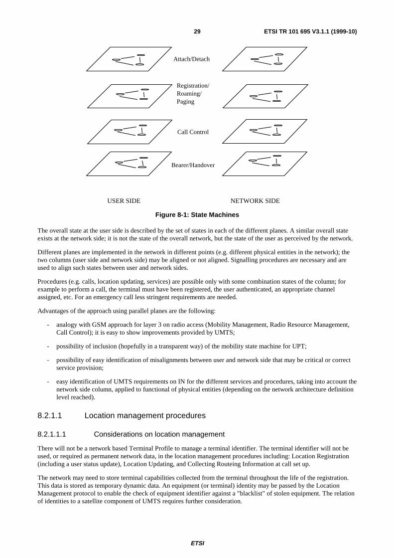
ETSI
ETSI TR 101 695 V3.1.1 (1999-10)29
Attach/Detach
Registration/ Roaming/ Paging
Call Control
Bearer/Handover
USER SIDE NETWORK SIDE
Figure 8-1: State Machines
The overall state at the user side is described by the set of states in each of the different planes. A similar overall stateexists at the network side; it is not the state of the overall network, but the state of the user as perceived by the network.
Different planes are implemented in the network in different points (e.g. different physical entities in the network); thetwo columns (user side and network side) may be aligned or not aligned. Signalling procedures are necessary and areused to align such states between user and network sides.
Procedures (e.g. calls, location updating, services) are possible only with some combination states of the column; forexample to perform a call, the terminal must have been registered, the user authenticated, an appropriate channelassigned, etc. For an emergency call less stringent requirements are needed.
Advantages of the approach using parallel planes are the following:
- analogy with GSM approach for layer 3 on radio access (Mobility Management, Radio Resource Management,Call Control); it is easy to show improvements provided by UMTS;
- possibility of inclusion (hopefully in a transparent way) of the mobility state machine for UPT;
- possibility of easy identification of misalignments between user and network side that may be critical or correctservice provision;
- easy identification of UMTS requirements on IN for the different services and procedures, taking into account thenetwork side column, applied to functional of physical entities (depending on the network architecture definitionlevel reached).
8.2.1.1 Location management procedures
8.2.1.1.1 Considerations on location management
There will not be a network based Terminal Profile to manage a terminal identifier. The terminal identifier will not beused, or required as permanent network data, in the location management procedures including: Location Registration(including a user status update), Location Updating, and Collecting Routeing Information at call set up.
The network may need to store terminal capabilities collected from the terminal throughout the life of the registration.This data is stored as temporary dynamic data. An equipment (or terminal) identity may be passed by the LocationManagement protocol to enable the check of equipment identifier against a "blacklist" of stolen equipment. The relationof identities to a satellite component of UMTS requires further consideration.

ETSI
ETSI TR 101 695 V3.1.1 (1999-10)30
The visited network must allocate and use a temporary identifier during a registration, comprising: the visited networkidentity; the service domain identity; the location area identity. This does not preclude this structured identity from beingchanged during the life of a registration. Location information allocated by the visited network will be sent and stored inthe home network as temporary data; this information will be used by the home network to control the service. The useof a User Identity, which is related to a subscription, is required by these procedures.
8.2.1.1.2 Introduction to the procedures
This State Model covers the following mobility procedures:
User Registration
This procedure is initiated by the user to notify the network of the presence of the user at a terminal. If this is the firstUser registered on the terminal, then location registration is invoked. If multiple subscriptions are allocated to a user,separate user registration procedures are required per subscription (see note). User registration might result in thestorage of service subscription related data at a network node near the current location of the terminal and a notificationof the registered service subscription to the home mobility provider.
NOTE: The nature of the subscriptions (mobility and/or service) is for further study.
User Deregistration
This procedure is initiated by the user to notify the network that the user will no longer be reachable. If multiplesubscriptions are allocated to a user, separate deregistration procedures apply. See also further: terminal initiated detachprocedure.
Location Update
This procedure is initiated by the terminal whenever the location information received via the radio path does notcorrespond to the location information currently stored in the terminal and the network or when the terminal is poweredon or upon a request from the network (e.g. location data lost in a network entity). The procedure results in updatedlocation information.
Location Registration
This procedure is initiated by the terminal when it enters another network domain where the terminal is not registeredyet (i.e. another public or private network or an area covered by another local mobility management entity within thesame network). The procedure results in the generation of new location information, might imply a deletion in theprevious domain of all data related to the terminal users and requires user registration procedures for all active servicesubscriptions at the terminal.
Location Deregistration
Location deregistration is activated when the terminal is deregistrated from the network. See also further: terminalinitiated detach procedure.
Where multiple users have registered on the same terminal, collective mobility management procedures may beperformed to reduce signalling load and database access load.
8.2.1.1.3 Information model for location management
The information model reflects the organization of the data needed for location management. The attributes store therelevant values for the location management and they are grouped in data entities (or data object classes). Each dataentity contains a number of instances which are distinguished by a key or identifier. The data entities are linked byseveral relationships to show the associations between the instances. Figure 8-2 shows the entities needed for locationmanagement.

ETSI
ETSI TR 101 695 V3.1.1 (1999-10)31
has registered
1..M
1
1
0..N
Location Area
LAI
1..N
Key:
belongs to
Key:
Terminal
TMTI
1 0..M
1
1..N
belongs to
1
1
Key:
User
IMUI
0..P
is registered in visited
is registered in visited
is located in
Key:
Service Domain
DI
Key:
Network
NI
Figure 8-2: Information model for location management
Description of the data entities
User
An instance of this entity indicates a user and is identified by the International Mobile User Identifier (IMUI). The useris the person or other actor (e.g. a machine) that uses the services for which he is authorized.
The attributes include:
- Temporary Mobile User Identifier (TMUI): this attribute is assigned to each user to cater for confidentiality onthe air interface. The TMUI is conceptually similar to the GSM TMSI;
- Network Identifier for Visited Network (NIvisited);
- Domain Identifier (DI);
- International Mobile User Number (IMUN): IMUN is a sequence of digits used to identify the called person (ormachine) in the network;
- User Service Profile: the user service profile reflects a collection of attributes indicating for each registeredservice the service characteristics.
Network
An instance of this entity indicates the network in which the user is located and it is identified by the NetworkIdentifier (NI). It contains network related data (e.g. routeing data).
Service Domain
The service domain is a geographical area in which a certain set of services is provided to the user. An instance of thisentity indicates a single service domain and it is identified by the Domain Identifier (DI).
ETSI
ETSI TR 101 695 V3.1.1 (1999-10)32
The attributes include:
- Network Identifier for the Visited Network (NIvisited);
- List of Mobile Terminal Roaming Numbers (MTRN): An MTRN is a temporary E.164 number assigned to theroaming user on a per call basis that allows routeing of a call towards the user or terminal.
Location Area
An instance of this entity indicates the geographical area in which a user/terminal pair is registered. An instance of thisentity is identified by the Location Area Identifier (LAI). The LAI contains the identities of the visited network, theservice domain, and the location area.
The attributes include:
- Domain Identifier (DI);
- List of Paging Areas: Paging areas are sub-areas of the location areas which are used for intelligent paging.
Terminal
An instances of this entity is the piece of equipment on which a user is registered and on which it can usetelecommunication services. An instance of this entity is identified by the Temporary Mobile Terminal Identifier(TMTI).
The attributes include:
- List of IMUI: Several Users may register on single terminal;
- Location Area Identifier (LAI): the stored LAI corresponds to the current location area. If the terminal movesinto a new location area, the LAI is updated due to a report of the new LAI from the terminal;
- Terminal Capabilities: the terminal capabilities reflect a set of values that indicate e.g. bandwidth, bearerservices, air interfaces that can be supported by the terminal.
8.2.1.2 Attach/Detach procedures
The attach/detach procedure is intended to notify the network about the status of the terminal on which the user hasregistered, i.e. whether the users registered on that terminal are reachable or not. In the case of incoming calls to a notreachable (detached) terminal the requests can be rejected at an early stage. This reduces the signalling and processingload in the system as well as network and radio resources (it prevents unnecessary paging).
At a user registration/deregistration the status of the user is implicitly set to attach/detach respectively. The statusinformation of the user should be part of user registration data.
It is a service requirement that this status data must be available to the home network to effectively manage INpersonalized service features. This data transfer may either be carried out:
- by relay during the attach/detach procedure; or
- by status information in the response to the request for routeing information during the call delivery procedures.
The better option should be selected considering the generated signalling load, efficiency and implementation costs.
NOTE: The expression "a user is registered on a terminal" means that a user has an association with this terminal.
User detachment
In the detach procedure the network is notified that the user is not reachable. In this context not reachable means that theterminal at which the user has registered is not able to receive calls. The detach procedure can be initiated by theterminal or the network.

ETSI
ETSI TR 101 695 V3.1.1 (1999-10)33
The detach procedure is performed in the visited network in following cases:
a) the terminal is switched off and the user(s) have not de-registered (terminal initiated);
b) the terminal gets out of coverage of the network. This can be detected by various mechanisms, e.g:
- when the terminal realizes that it is leaving the coverage area, it sends a detach request to the network andsets itself to detach status (terminal initiated detach by location deregistration);
- the terminal fails to answer 'n' times to a location update request or paging request; the network marks theterminal and possibly also the users on that terminal as detached. Correspondingly, the terminal sets itsstatus to detached when during a period of time no contact with the network has been possible;
c) the UIM is removed from the terminal (terminal initiated detach by user deregistration).
This list does not aim to quote all possible detection options for a detach situation. The detach procedure might result inthe deletion of data at the RAN if the RAN performs local mobility management functions.
User attachment
In the attach procedure the network is notified that the user is reachable again. In this context reachable means that theterminal at which the user has registered can receive calls. The attach procedure is always initiated by the terminal.
The attach procedure is performed in following cases:
a) a powered up terminal, with users registered on it becomes reachable again (attach by location update or otheractivity);
b) a switched off terminal, with users still registered on it, is powered on again (attach by location update);
c) the UIM is inserted into a powered up terminal (attach by user registration).
Attach after detach procedures can only be successfully executed if the terminal and the registered users did not moveduring the detach period outside the area within which temporarily assigned identifiers are valid.
The procedure might result in the deletion of data at the RNC if the RAN performs local mobility managementfunctions.
8.2.1.3 Handover control
Handover cases may vary from a simple change of radio channel at the same mobile-base station link, through to acomplete change of point of attachment to include a re-direction and re-routeing of the network side of the connection.In the following subclause only connection-oriented services and their signalling are included.
8.2.1.3.1 Functional and procedural requirements for handover
This subclause identifies some key requirements put on handover from a functional and procedural point of view. Theseare derived from analysing the different handover conceptual phases which are:
a) Monitoring and collecting of data;
b) Decision;
c) Path creation and switching;
d) Completion and route optimization.
These phases are defined as follows:
- monitoring process: this process collects radio measurements, aggregates these data (e.g. averaging) and forwardsthem to the decision entity. This data gives indication on the quality of the radio link and on the radioenvironment (signal profile, path loss, ...), and is used for handover decision processing;

ETSI
ETSI TR 101 695 V3.1.1 (1999-10)34
- decision process: the decision process comprises two sub-processes which can take place simultaneously. Thefirst one determines when the handover must be triggered by comparing collected data with pre-set thresholds.The second one selects the target cell according to pre-set criteria defined for the handover;
- path creation and switching: this process creates a new radio link and the associated service path through thefixed network and performs any necessary switching (possibly bridging) and path combination;
- completion and route optimization: this process frees up any unneeded resources. Finally, once the handover iscompleted, a rerouteing can be triggered to allow for a new optimal routeing.
The involvement of FEs during the different handover phases is described below.
Monitoring process
This phase deals with the supervision of the local environment as perceived by the mobile terminal (current status of theradio link, global interference level within a given area, serving and neighbouring cell congestion, ...). Collected data(e.g. radio measurement samples, traffic local within a local area, ...), which has only a local significance, needs to beprocessed to monitor the environment experienced by the mobile terminal and to prepare the decision process. Thisphase therefore only has meaning in a local context (i.e. a given area within the radio access sub-network) and must notinvolve IN related control function (e.g. SCAF, SCF). Functional involvement during the operations needed for thisphase are the following:
- collection of radio data only involves the RRC and/or the MRRC;
- collection of traffic data is performed by radio access subsystem entities. Traffic data is extracted by the RACFfor processing purpose (both for the monitoring and decision phases);
- monitoring involves the RACF.
Decision process
Handover decision is based on the processing of pre-set algorithms using collected data. Depending on the monitoringprocess (e.g. averaging window, number of averaged samples), this data will give a more or less accurate picture of thelocal environment associated with the radio link to be handed over (e.g. current radio link quality, interference levelgenerated by the surrounding cells, traffic load around the serving cell, ...). The result of the decision is to determineanother local environment (identified by the target cell) in which the radio link could be reasonably maintained for awhile. Handover decision is therefore based on a very close observation of the 'living' behaviour of the system.
One of the IN principles is to ensure independence of the SCF vis-à-vis the backbone network: it is stated in ITU-TRecommendation Q.1201 [4] that 'service logic must be implemented in a service-, network configuration-, network typeindependent way'. The decision phase is based on some processing capabilities or logic which should therefore not be INspecific. Processing control functions needed for handover decision are performed by the RACF.
NOTE: It may occur that access right needs to be checked during the decision phase, e.g. for inter-networkhandover. This should not be considered as being a part of the decision process, but as user service profilechecking needed to be performed for the support of mobility between different administrative domains (inthe same way as for other mobility procedures, e.g. user registration, location registration, etc.). Moregenerally, the involvement of the SCF is not required for the decision processing by itself, but may beneeded for exchanging data between geographical and/or administrative domains such as:
- the authentication key between different locations;
- relevant data for the handling of charging and accounting in case of inter-network handover. In thislatter case, the SCF should be triggered via the CCF/SSF because the data to be exchanged hassignificance only in a context associated with the call;
- user information related to the service profile (e.g. for access right checking).
Path creation and switching
This phase clearly involves the BCF, RBCF and BCAF. Co-ordination between these various Bearer Control functionsis performed by the RACF.

ETSI
ETSI TR 101 695 V3.1.1 (1999-10)35
Completion and route optimization
Completion consists in releasing the old path together with related instances of control functions and therefore involvesbearer control functions. The release of the old radio link will be performed by the invocation from the RBCF/BCAF tothe RRC/MRRC to free up the unneeded radio resource.
Some logic control function is also needed to provide routeing information (see note below). Upon knowledge of thisinformation, the backbone network (e.g. PSTN, ISDN, ...) performs route optimization. For that purpose, bearer controlfunctions are activated and piloted by the CCF (the CCF is the only entity handling the call context).
NOTE: The location of this function, e.g. in the SCF or in a dedicated SCF-like for handover, needs furtherinvestigation.
Key requirements
The discussion above is summarized in the following functional and procedural requirements for handover:
HO_F_1 Handover procedures should be harmonised between the different handover types.
HO_F_2 Processing of data having local significance (e.g. radio measurements, traffic load within a local area, ...) should be performed independently from the IN Service Logic Program (SLP). As a consequence, the handover monitoring and decision phases should not involve IN Service Control Functions (e.g. SCF).
HO_F_3 Handover procedures will basically use bearer control functions (e.g. RBCF, BCF) and radio associated control functions (e.g. RACF).
HO_F_4 The SCF may only be triggered in case of handover between different geographic and administrative domains. This should be possible in order to cater for the transfer of relevant information (e.g. radio related identities similar to the LAC in GSM, routeing information, authentication key, charging and
accounting data) needed for:
- determination of signalling destination address;
- route optimization;
- ensuring integrity of the ongoing call; and
- correct handling of the administrative procedures.
8.2.2 Functional model for UMTS
8.2.2.1 Requirements for the UMTS functional model
Figure 8-3 shows the functional model for IMT2000 enhanced with functions for UMTS. It reflects the basic concepts ofUMTS and commonalties with other network-concepts (such as e.g. IN, B-ISDN), namely:
- the separation of switching, service control and service data functionality;
- the support of call and connection control (bearer control);
- the separation of call unrelated interactions;
- the support of call related interactions;
- the separation of terminal and network related functions (these functions will be separated by the radio interfacein the case of UMTS);
- integration of terminal functions for wired and wireless access.
The model shows the functional entities (FEs) and the functional relationships between these FEs, and provides the basisfor the development of service specific functional models. Each FE of the generic functional model represents a group ofservice specific FEs.

ETSI
ETSI TR 101 695 V3.1.1 (1999-10)36
In a specific network, several FEs of the same type may exist. However, in the generic functional model, each FE type isshown only once. A relationship between two FEs of the same type is shown as a "relation loop" starting and ending inthe same FE.
In the model, a distinction has been made between functions residing at the mobile side of the radio interface and thefunctions residing at the network side of the radio interface. The functions at the mobile side together form thefunctionalities required at the access (mobile) side of the concentrator formed by the radio interface (e.g. pagingresponse, initial access, authentication, channel coding, ciphering, etc.).
In principle the model should support the de-coupling of the radio access functionalities and possibly radio bearercontrol from the user/network interactions necessary to manage and control users and telecommunication services whichshould be as common as possible with other telecom networks (e.g. ISDN, B-ISDN). In more detail, the followingtentative set of functions would be involved in such a de-coupling:
- control and management of point to multi-point associations from the network to the users;
- possible interworking functions necessary to adapt network protocols to the specific radio and proceduralrequirements/constraints;
- translation of the mobile terminated call request/paging into the radio network specific procedure.
It may represent the border between handover procedures that can be treated completely at the UMTS access level andhandover procedures that require the involvement of other entities in the fixed part of the network.
8.2.2.2 The IMT2000 functional models
In the IMT-2000 functional models, the functions required for IMT-2000 service support have been grouped intoFunctional Entities (FE) and the functional relationships between these FEs have been indicated. Since there are twopossible approaches to the allocation of call control and connection control related functionality, two alternatives areidentified: Alternative 1 with integrated call control and connection control FEs and Alternative 2 with separated callcontrol and connection control FEs. This results in the two functional models shown in figures 8-3 and 8-4 respectively.
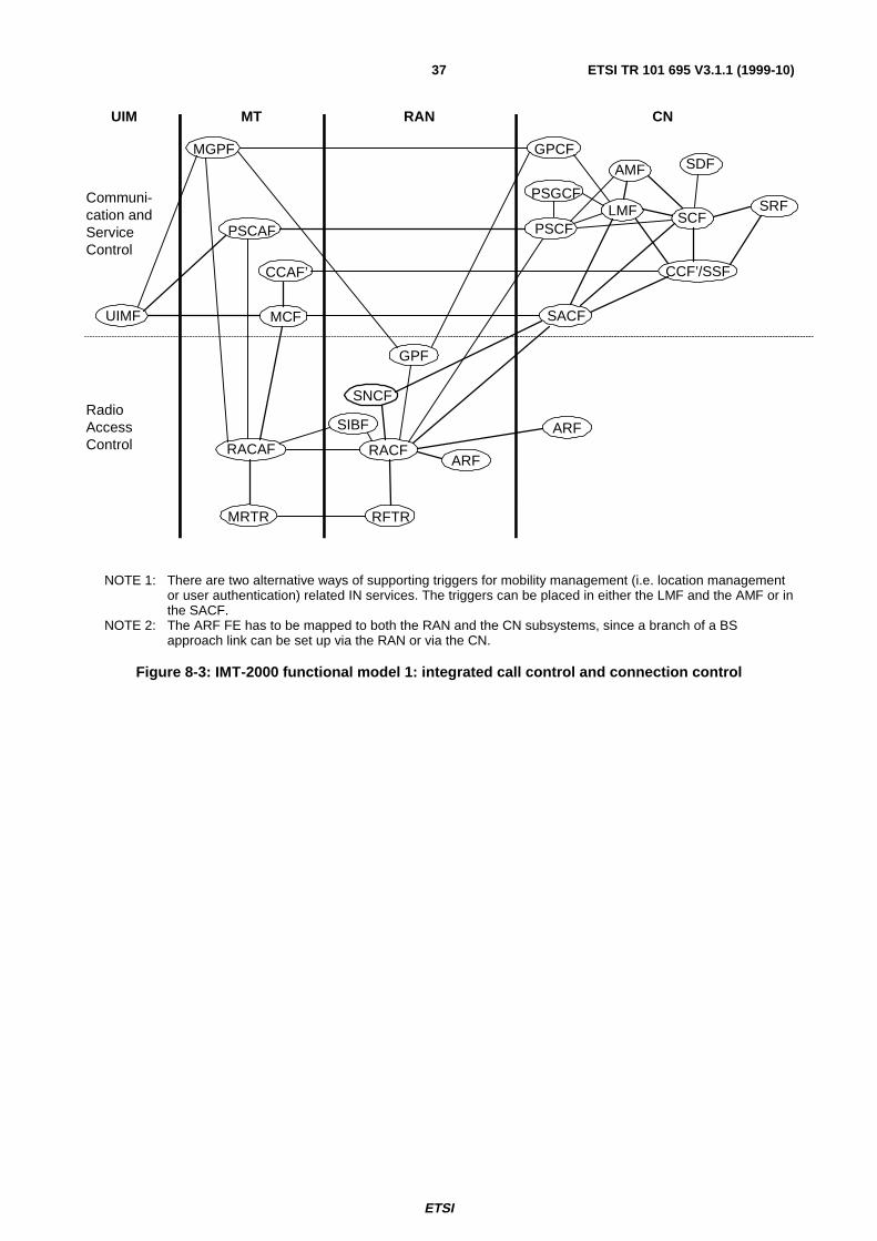
ETSI
ETSI TR 101 695 V3.1.1 (1999-10)37
AMF SDF
MRTR RFTR
ARFSIBF
SACFMCFUIMF
SCFLMF
RACAF
SRF
CCAF’
RACFARF
CCF’/SSF
UIM MT RAN CN
SNCF
PSCAF PSCF
PSGCF
RadioAccessControl
Communi-cation andServiceControl
GPCFMGPF
GPF
NOTE 1: There are two alternative ways of supporting triggers for mobility management (i.e. location managementor user authentication) related IN services. The triggers can be placed in either the LMF and the AMF or inthe SACF.
NOTE 2: The ARF FE has to be mapped to both the RAN and the CN subsystems, since a branch of a BSapproach link can be set up via the RAN or via the CN.
Figure 8-3: IMT-2000 functional model 1: integrated call control and connection control

ETSI
ETSI TR 101 695 V3.1.1 (1999-10)38
AMF SDF
MRTR RFTR
ARFSIBF
SACFMCFUIMF
SCFLMF
RACAF
SRF
CCAF’
RACFARF
CCF’/SSF
UIM MT RAN CN
CnCFCnCAF
SNCF
PSCAF PSCF
PSGCF
RadioAccessControl
Communi-cation andServiceControl
GPCFMGPF
GPF
CnCF
NOTE 1: There are two alternative ways of supporting triggers for mobility management (i.e. location managementor user authentication) related IN services. The triggers can be placed in either the LMF and the AMF or inthe SACF.
NOTE 2: The ARF FE has to be mapped to both the RAN and the CN subsystems, since a branch of a BSapproach link can be set up via the RAN or via the CN.
Figure 8-4: IMT-2000 functional model 2: separated call control and connection control
8.2.3 IN enhancements to support UMTS
8.2.3.1 Impact of handover on IN
Handover is a means of rerouteing a connection in-call or out of call. I.e. handover does not alter the call state or theservice but only replaces one or several consecutive connection elements with one or several other consecutiveconnection elements. Many handovers can be dealt with in access networks. In this subclause, it is assumed that somefunctions for some types of handover are allocated to a special SCF for handover (SCF-HO).
8.2.3.2 Triggering of IN control functions for handover
For the triggering of IN functions on the SCF-HO, three alternatives are considered:
a) Triggering from SSF (BCSM) to SCF-HO
The existing CS triggering mechanism is used. This means that for handover triggering, the trigger from the radio part ofthe network must be notified to the SSF via the BCSM. The impact is that bearer related events must be modelledsomehow in the BCSM.

ETSI
ETSI TR 101 695 V3.1.1 (1999-10)39
b) Triggering from SSF (connection/bearer control) to SCF-HO
As handover is tied more closely to bearer control than to call control, it makes sense to separate this bearer-relatedtriggering from the call-related triggering. Such a 'bearer-related' relationship does not exist in the IN CS1 modellingwhere no separation between call and connection control is made. Nevertheless, as studies on the integration of IN andB-ISDN are starting now, it might be considered. It requires a separate 'connection-related' model in the SSF which cancommunicate with the SCF-HO.
c) Triggering from RACF to SCF-HO
In an alternative approach, the trigger is forwarded to the SCP-HO via a RACF-to-SCF-HO relationship. It is howevernecessary to have a mechanism for correlating these triggers with a specific call.
Discussion
In scenario 'a', the interaction with other IN services acting on the same call is a serious problem:
1) See also figure 8-5. The BCSM mechanism does not support parallel processing of events. For example, a UMTScall is in the active state, i.e. two users (at least one of them mobile) are communicating. The originating userwants to activate a specific mid-call feature/service. His prompt causes the event DP8 (O_Mid_Call). The SSFinforms the SCF and call processing is interrupted. Some milliseconds later a handover request occurs. If the callis active this would lead to an O_Handover (for example), but in this situation the BCSM is already suspendedand the mechanism is not capable of processing the handover immediately. This is only possible after the userrequest has been dealt with and the call is again in PIC5 (O_Active). This delay in handover triggering will meanan important (and often fatal?) reduction of the quality of the UMTS call.
5. O_Active
8 x
O_Mid_Call O_Handover
Figure 8-5: A midcall event delays immediate processing of handover request
2) Furthermore, what if there is already a control relationship between SCF and SSF for this UMTS call? With theCS1 standards, DP processing allows one control relationship at a time to prevent uncontrollable serviceinteractions.
Due to the problems mentioned for scenario 'a', the use of the existing BCSM triggering mechanism for triggeringhandover is not feasible. Scenario 'b'. is feasible, but requires (besides the already existing relationship between SCF andBCSM) a new relation between SCF-HO and bearer control in the network. Scenario 'c'. is feasible and only requires acorrelation between the triggering and a specific call for which the handover is required.
8.2.3.3 Execution of intra-switch handover
For the requirements for the execution of handover, different cases are distinguished, from a simple handover whereonly a connection towards a new base station has to be established to the most complex handover (between differentdomains), where not just a new connection has to be established but also the call control process and existing servicecontrol processes have to be transferred.
Control bearers may be modelled as non-switched relationships. Reconfiguration of control bearers takes place in thephysical plane whether a traffic bearer connection is established or not. This reconfiguration has no impact on theswitching functions controlled by the service logic (i.e., no impact on the BCSM). It is handled by the lower layerprotocols (network layer).

ETSI
ETSI TR 101 695 V3.1.1 (1999-10)40
Traffic bearer handover applies only to switched call connections. It can take place at any time during call processing(call set-up, established call, call release) and in parallel with any service processing.
In this subclause only the 'traffic bearer handover' in a switch is covered.
Handover I: Traffic bearer handoverThe most simple case of handover in which IN is involved is a handover from one base station or radio access system toanother, both connected to the same SSP (see figure 8-6). This means that call control and service control remain thesame and that there is only change of connection elements used in the call.
SCP
SSP
Handover
Request
A
B B'
Figure 8-6: Bearer Handover
Requirements on IN for handover execution depend on the execution mechanism:
A) perform handover via BCSM manipulation (at a 'call control' level). Issues here are:
- the call state itself should not change because it is still the same call;
- what is the relation between the different call segments etc.;
- if triggering occurred via RACF-to-SCF-HO: which call has to be manipulated (correlation), how tointerrupt it, is there another IN service active on that call (service feature interaction)?
B) perform handover directly in 'connection/bearer control'. Since handover is a bearer related issue, an alternativemight be found in the separation of call and connection control, where the SCF-HO in case of handover interactswith the bearer control while the call itself remains unchanged. A separate model might be required.
These two alternatives are considered in more detail in the following.
In a switch (CCF/SSF), any call in progress - whether an IN service is invoked or not - is modelled by the association ofan O- and a T-BCSM. When no service is requested no suspension DP is armed.

ETSI
ETSI TR 101 695 V3.1.1 (1999-10)41
LEBCSM
RACF
TEBCSM
MS
i i
traffic bearer call control bearerservice control bearer
Initial configuration
network
f = final relationshipi = initial relationship
mobile network access
LEBCSM
RACF
TEBCSM
f
f
Final configuration
network
MS
SCF-HO SCF-HO
Figure 8-7: Basic handover configurations
Several handover procedures could be developed; two of them which reduce the impact of traffic bearer handover on theBCSM are described in the following.
Introduction of a dedicated handover state machine HSM
This proposal is based on the concept of call/connection separation. The principle being to keep the call contextunchanged during handover execution.
An initial bearer context Bci will be replaced by a final bearer context Bcf.
Introduction of a dedicated HSM, controlled by the HCL in the SCF-HO would enable separation of the view of theconnections for the purpose of handover processing.
The HSM provides the SCF-HO with a view of the configuration of the traffic bearer connections. The state transitionsof the HSM might be influenced by the state transition in the BCSM.
The handover request could be conveyed either by a connection associated message or by a mobility message receivedvia the RACF-to-SCF-HO interface.
The HSM models the configuration of the legs involved in the handover. Seamless handover could be achieved by three-party conference techniques.
Further study is necessary to define a set of indications between the HSM and BCSM to co-ordinate call and handoverprocessing. Particularly, it could be necessary to halt (to place the BCSM in a wait state) during handover.
Both handovers on originating and terminating legs can be handled in the same way.

ETSI
ETSI TR 101 695 V3.1.1 (1999-10)42
O-BCSM T-BCSM
SCF-HO SCF
SSF/CCF
BCSM-HSM indications
HSM
A Call ctrl relationship
Ai BcBearer ctrl relationship
BCF
A: Calling userAi: Initial leg/connection used to carry A-speechBc: Bearer context
Figure 8-8: Control of handover in alternative B
O-BCSM T-BCSM
SCF-HO SCF
SSF/CCF/BCF
Ai
HSM
Bci
A O-BCSM T-BCSM
SCF-HO SCF
HSM
A
Ai Bci1 2Af Bcf
HOR
SSF/CCF/BCF
3
O-BCSM T-BCSM
SCF-HO SCF
HSM
Bcf
A
Af
SSF/CCF/BCF
Figure 8-9: Use of the HSM for handover
Step 1: initial configuration; (T-BCSM may not be active at the time of handover).
An HSM instance associates the Call Control BCSM and the Bearer context Bci.
Step 2: a handover request associated with Af is received by the CCF/SSF, a new Bcf instance is created.

ETSI
ETSI TR 101 695 V3.1.1 (1999-10)43
HSM ensures correlation and switch-over between Bci and Bcf instances.
Step 3: final configuration, HSM is associated with the new Af; Ai is released.
8.2.3.4 Execution of inter-switch handover
Inter-switch handover implies that a call control entity should be initiated in the new switch. Optimization requires thatall associations are transferred to this new entity. Another issue arises if the established connection, at a given node, isalready under the control of an IN service logic e.g. a UPT call, when a handover is necessary at this node.
Transfer of control to another node, in view of optimizing the connections, will not be always allowed nor feasible.Tromboning could not be avoided at least as long a control relationship exists between the node and a ServiceProcessing Point.
One could suggest one of the following:
- initial connections in the fixed network are always maintained: generally resulting in tromboning in connections;
- tromboning is avoided when the connection is not already controlled by a service logic;
- tromboning is eliminated when service control relationship no longer exists.
8.2.3.5 State modelling for handover
8.2.3.5.1 Introduction
In this subclause a state model for handover control and one for bearer control are presented in order to define theactions taken in the switch during handover. For the time being only inter-RACF, intra-switch handover is consideredfor simplicity. This kind of handover does not require Control Point Transfer in the core network. For the models, aseparation between the Call Control and the Bearer Control is assumed. This separation could be a first step towardsIN/B-ISDN integration and also a possible way to solve handover problems, with direct control and manipulation ofbearers by means of the SCF.
8.2.3.5.2 Evolution of IN for the integration with B-ISDN
The concept of separation of Call Control (CC) and Bearer Control (BC) functions has an impact on IN, especially forthe Service Switching Function (SSF) and the Basic Call State Model (BCSM). The separation of CC and BC is alsovery attractive for the support of mobility services like handover, where is needed the direct control and manipulationsof the bearer.
As far as IN is concerned, the integration of IN with B-ISDN means evolution of the SSF architecture, BCSM modellingand the SSF-SCF interface. The simplest way to evolve towards an IN/B-ISDN integration is to take the currentmodelling of the SSF (figure 8-10) and try to enhance it by adding the new functionality for the support of broadbandservices. This approach implies a limited integration between IN and B-ISDN, because IN is not directly involved in thecontrol of the bearer connections.
In the new architecture proposed in figure 8-11 the SSF is split into two sub-entities: the SSFCC (Service SwitchingFunction - Call Control) processes event indications to or from the state model responsible for the CC; the SSFBC(Service Switching Function - Bearer Control) processes event indications to or from the state model responsible for theBC. In this way IN is more involved in the bearer connection process as it can interact directly with BC through theSSFBC.

ETSI
ETSI TR 101 695 V3.1.1 (1999-10)44
SSF
CC
BC
B_CCF
Figure 8-10: Current architecture of SSF
B_SSF
to SCFto SCF to SCFto SCF3
SSF SSF
CC
BC
BCCC
Figure 8-11: Proposed architecture of SSF
8.2.3.5.3 Handover State Model
Figure 8-12 shows a first proposal for an IN state model. A DP starts with an outgoing message to the SCF and endswith an incoming message from the SCF. The message numbers from the information flow diagrams are indicated at theleft side (for intra-LE, inter-RACF handover).

ETSI
ETSI TR 101 695 V3.1.1 (1999-10)45
1. null (bearer.active)
2. bearer.reservation
3. bearer.connecting
4. handover.switching
5. bearer.releasing
HO.complete
bearer reserved
bearer connected
handover executed
reservation denied
connection failure
switching failure
DP1
DP2
8
11
16
20
27
28
32
35
DP3
DP4
DP5
DP7
DP6
Figure 8-12: Handover state model
Handover is initiated from the state in which the bearer that will be handed over is active. It is the null PIC for the HSM.The first transition with message 8 reflects the fact that handover is initiated from the SCF. The DP before PIC2 isomitted because no further actions are required from the SCF. The HSM simply continues in the "bearer.reservation"PIC. In this state the CCF interacts with the BCF to reserve the new bearer (see next subclause).
After these actions, the HSM enters DP1 where a notification is sent to the SCF (message 11) and the processing ofhandover is suspended in the switch. After processing, the SCF sends a request to connect the new bearer (message 16),and processing in the CCF is resumed in PIC3 'bearer.connecting'.
When the bearer connection is established, message 20 is sent to the SCF and CCF/BCF processing is suspended in DP2until message 27 SwitchHOCommand (network initiated and terminal initiated HO) from the SCF is received. Thismessage is a request for the actual switching for handover. The necessary actions are performed in PIC4'handover.switching'.
After the switching between old and new bearer has been completed, message 28 SwitchHOComplete is sent to the SCF.The actual handover has been executed, but the old bearer is still connected. Message 32 ReleaseBearer (networkinitiated HO) or message OldRadioLinkReleasedInd (terminal initiated HO) is the request from the SCF to release thisold bearer. When it has been released (modelled in PIC5), a notification is sent to the SCF (message 35) and the HSMreturns to 'null (bearer.active)' where only the new bearer is active.
In a next step, the regular bearer set-up and release could be added to achieve a complete state model.
8.2.3.5.4 Single Bearer State Model
This subclause presents an IN-like state model for the control of a single bearer.
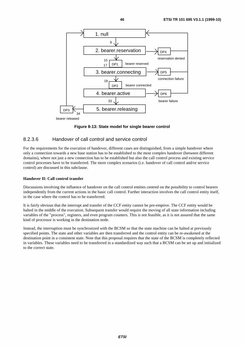
ETSI
ETSI TR 101 695 V3.1.1 (1999-10)46
1. null
2. bearer.reservation
3. bearer.connecting
4. bearer.active
5. bearer.releasing
bearer released
bearer reserved
bearer connected
reservation denied
connection failure
bearer failure
DP1
DP2
9
10
17
18
33
34DP3
DP4
DP6
DP5
Figure 8-13: State model for single bearer control
8.2.3.6 Handover of call control and service control
For the requirements for the execution of handover, different cases are distinguished, from a simple handover whereonly a connection towards a new base station has to be established to the most complex handover (between differentdomains), where not just a new connection has to be established but also the call control process and existing servicecontrol processes have to be transferred. The more complex scenarios (i.e. handover of call control and/or servicecontrol) are discussed in this subclause.
Handover II: Call control transfer
Discussions involving the influence of handover on the call control entities centred on the possibility to control bearersindependently from the current actions in the basic call control. Further interaction involves the call control entity itself,in the case where the control has to be transferred.
It is fairly obvious that the interrupt and transfer of the CCF entity cannot be pre-emptive. The CCF entity would behalted in the middle of the execution. Subsequent transfer would require the moving of all state information includingvariables of the "process", registers, and even program counters. This is not feasible, as it is not assured that the samekind of processor is working in the destination node.
Instead, the interruption must be synchronized with the BCSM so that the state machine can be halted at previouslyspecified points. The state and other variables are then transferred and the control entity can be re-awakened at thedestination point in a consistent state. Note that this proposal requires that the state of the BCSM is completely reflectedin variables. These variables need to be transferred in a standardized way such that a BCSM can be set up and initializedto the correct state.

ETSI
ETSI TR 101 695 V3.1.1 (1999-10)47
SCP
SSP SSP
A
BB'
- Call state
2) Handover Request
1) Initiate handover process
3) SetUp with embedded:
Figure 8-14: Call control handover to another SSP
Handover III: Call Control and Service Control Association Transfer
This section describes scenarios envisaged for situations in which a handover should be executed, resulting in calltransfer from one SSP to another, while an IN service is already acting on the call:
A) Direct transfer
The principle here is that the association with the SCP in the IN is aborted, after which the handover may take place.This is only acceptable where the control relationship only existed for low priority feature support, and therefore this isnot an acceptable solution.
query other association
abort
transfer control
Figure 8-15: Direct transfer
B) Delayed transfer
An alternative is to delay the transfer and/or the handover.
Following this assumption, figure 8-16 is introduced, where the associations are being kept open until all unfinishedtransactions over the existing associations are terminated. Waiting for transactions to finish can take valuable time,delaying the handover.
query other association
receive query response
transfer control
Figure 8-16: Delayed transfer, delayed handover
In figure 8-17, the control point actually waits until the transactions are finished while the handover proceeds. Of course,while waiting for the transactions to finish, the call control entity would not be allowed to setup or accept newassociations, which is probably not feasible.
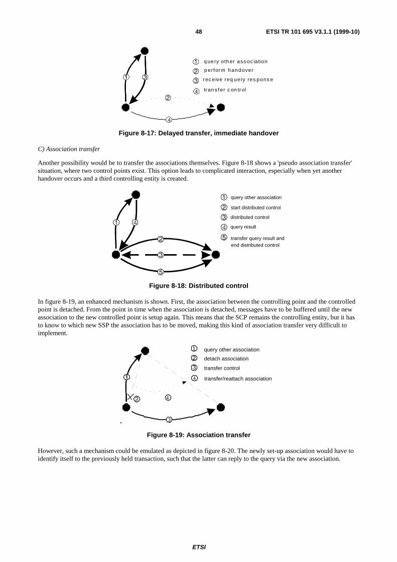
ETSI
ETSI TR 101 695 V3.1.1 (1999-10)48
4
4
q ue ry oth er ass oc iation
r ec eive req uery res pons e
tran s fer c on tr ol
p er for m h an d over
Figure 8-17: Delayed transfer, immediate handover
C) Association transfer
Another possibility would be to transfer the associations themselves. Figure 8-18 shows a 'pseudo association transfer'situation, where two control points exist. This option leads to complicated interaction, especially when yet anotherhandover occurs and a third controlling entity is created.
query other association
start distributed control
distributed control
query result
transfer query result and end distributed control
Figure 8-18: Distributed control
In figure 8-19, an enhanced mechanism is shown. First, the association between the controlling point and the controlledpoint is detached. From the point in time when the association is detached, messages have to be buffered until the newassociation to the new controlled point is setup again. This means that the SCP remains the controlling entity, but it hasto know to which new SSP the association has to be moved, making this kind of association transfer very difficult toimplement.
.
4
3
4
1 query other association
detach association
transfer control
transfer/reattach association
Figure 8-19: Association transfer
However, such a mechanism could be emulated as depicted in figure 8-20. The newly set-up association would have toidentify itself to the previously held transaction, such that the latter can reply to the query via the new association.

ETSI
ETSI TR 101 695 V3.1.1 (1999-10)49
.
34
4 5
5
6
6
query other association
hold
abort
transfer control
(incl.old associatiation origins)
setup
resume
association
Figure 8-20: Emulated association transfer
In an IN, this can be done as depicted in figure 8-21. The handover request as sent by the SCP leads to a set-up messageto a new SSP, including information about the SCP, the service that was invoked and the actual call state. The new SSPsends a trigger containing the service information to the SCP after which the control association is resumed.
SCP
SSP SSP
A
BB'
2) Handover Request
-ServiceId
1) Suspend service processing
5) Continue service processing
4) ReTrigger
3) SetUp enbedded:-Call state
-Serviceld-SCFid
-SCFid-Serviceld
Figure 8-21: Call control and service control association transfer
Handover IV: Call control and service control transfer
The most complex scenario is when there is not only a change of SSP, but also a new SCP is involved, e.g. because it isan inter-network handover. The scenario depicted in figure 8-22 can be used:
SCP SCP
SSP SSP
2) Handover Request
-Serviceld-SCFid
1) Interrupt service processing
4) ReTrigger-SCFid
3) SetUp with embedded:-Call state-SCFid-Serviceld
Figure 8-22: Call control and service control transfer

ETSI
ETSI TR 101 695 V3.1.1 (1999-10)50
NOTE: Although the presented scenarios for control point transfer are focused on the SSP and SCP processes, themechanisms can be applied more generally.
9 Application DomainAn Application Programming Interface (API) provides a well-defined set of procedures for interfacing softwareapplications. In this context it is noted that:
- a UMTS-Client API can be used for support of UMTS-Terminal client applications. As part of the terminalvirtual machine, it could support the Virtual Home Environment (VHE) via the Mobile Agent paradigm.Standardization could facilitate third-party software development across terminal brands;
- a UMTS-Server API can be used for support of UMTS server applications. Standardization could facilitate thirdparty software development across network suppliers. The adoption within ETSI of a common UMTS-ServerAPI for the CTM/GSM-UMTS and other core network, would provide a basis for network-independent UMTSapplications.
UMTS-Client
API
Client
UMTS-Server
API
ServerApplications
UMTS
Core Network(s)
TerminalRadioPart
BSRadioPart
UMTS Terminal(Application Client)
UMTS Application Domain(Application Server)
Applications
UMTS
Figure 9-1: UMTS APIs
Proposed requirements
1) A UMTS-Client API should be specified for UMTS terminals.
2) A UMTS-Server API should be specified for the UMTS Application Domain.
The UMTS Task Force recommends the definition and use of a common UMTS-Server API.

ETSI
ETSI TR 101 695 V3.1.1 (1999-10)51
Annex A (normative):Role model related material
A.1 UMTS role model (UMTS 22.01)In ETSI, Working Group SMG1 has the responsibility for defining UMTS system and services. As a consequence, it isresponsible for the definition of the UMTS role model.
SMG1 has reached a consensus on the model described below. This role model is presented in the TechnicalSpecification UMTS 22.01 (version 3.0.0) [7].
A.1.1 Overview of the UMTS role model in UMTS 22.01The role model has been developed in the following steps:
- identification of entities (e.g. persons, legal entities, or machines) involved as actors in UMTS service provisionand use;
- identification of relationships between actors involved in the provision and use of UMTS services;
- definition of roles of actors within the relationships.
A representation of the resulting role model is depicted in figure A.1.
User Network Operator
Subscriber Service Provider
Value Added Service Provider
Subscription-Subscriber Profile Management
Billing
Delegation of Service Usage
User Service Profile Management Delegation
of Service Provision Accounting
Usage
Payment
Billing
Billing
Payment
Usage
Payment
Payment
Payment
Figure A.1: UMTS role model (UMTS 22.01)
A.1.2 Description of roles in UMTS 22.01Subscriber is a role in which a person or other entity has a contractual relationship with a service provider on behalf ofone or more users. A subscriber is responsible for the payment of charges due to that service provider.
User is a role in which a person or other entity authorized by a subscriber uses services subscribed to by the subscriber.
Service Provider is the role that has overall responsibility for the provision of a service or set of services to usersassociated with a subscription because of the commercial agreement established with a subscriber (the subscriptionrelationship). Service provision is the result of network operator and service provider service capabilities combining.The subscriber profile is maintained by the service provider.

ETSI
ETSI TR 101 695 V3.1.1 (1999-10)52
NOTE: The definition of the service provider does not prevent the actor playing the role to delegate serviceprofile and service management function to another actor, such as a network operator, which then acts onbehalf of the service provider.
Network Operator is the role that combines service provider service capabilities to its own service capabilities toenable users to use services. The network operator provides capabilities to enable users to obtain services in eitherpublic and/or private environments (business or residential and possibly via unlicensed spectrum). It may be appropriateto subdivide the network operator function and interfaces may need to be identified; however such subdivisions do notappear to have any implications from a subscriber service perspective. The actor that plays the network operator rolemay use the radio access function provided by another actor, for example a satellite access operator.
Value Added Service Provider provides services other than basic telecommunications service (e.g. content provisionor upper layer capabilities) for which additional charges may be incurred. These may be billed directly to the subscriberor user, or may be billed via the subscriber's service provider.
As bilateral agreements between a large number of Network Operators and Service Providers would be impractical,some methods of establishment of roaming relationships are currently being studied within SMG1. These methods arelikely to include a new role called a "Roaming Broker".
A.1.3 Relationships in the provision and use of UMTS servicesThe following paragraphs briefly describe the relationships identified:
Subscription is a contractual relationship (i.e. basically a commercial) between two actors, one in the role of subscriber,the other in the role of service provider. It defines, amongst others things, the services subscribed to, the tariffs that willbe applied and the services and rights delegated to the subscriber's users for each subscriber. After subscription, thesubscriber profile may be modified by the subscriber through the subscriber profile management relationship.
Delegation of service usage is a relationship between two actors, one in the role of subscriber, the other in the role ofuser, in which the subscriber authorizes the use of (a part of) the telecommunication services subscribed to.
User service profile management is a relationship between two actors, one in the role of user, the other in the role ofservice provider, devoted to modification of user service profile parameters that the user has access to.
Usage of a telecommunication service in respect of subscription profile involves two actors, one in the role of user, theother in the role of network operator, the latter providing a particular instance of the required service through acombination of both service provider and network operator service capabilities.
Accounting for the usage of telecommunication services in the simplest case, is a relationship between two actors, onein the role of network operator, the other in the role of service provider; the first one notifies the latter on the use oftelecommunication services by the users of the service provider's subscribers. This leads to account settlement. Theaccounting relationship is a prerequisite to billing.
Billing for the usage of a telecommunication service is a transaction between the two actors involved in the subscriptionrelationship where the subscriber receives notification (bill) of the monetary counterpart of the use of telecommunicationservices by its users. This leads to bill settlement. Only the service provider can establish the bills by associating useraccounting data with the responsible subscriber (thanks to its commercial data base).
Usage is a relationship between two actors, one in the role of Value Added Service Provider, the other in the role ofNetwork Operator, the former using basic telecommunication services provided by the latter.
A.1.4 Hybrid role modelsSMG1-UMTS has issued a liaison "Response to NA6 LS ref Role Models of SMG1-UMTS and MoU 3GIG" whichaddresses the mapping of the "GSM MoU TG.25 Role Model for UMTS Roaming" onto the role model contained inUMTS 22.01 [7].

ETSI
ETSI TR 101 695 V3.1.1 (1999-10)53
Home Mobility Provider
Regarding the Home Mobility Provider, the liaison notes "The concept of a Home Mobility Provider role as defined inTG.25 does not exist in 22.01. The functionality of this role is seen to be part of either the Service Provider role or theNetwork Operator role as defined in 22.01. SMG1 UMTS does not see the need for the home network mobility to beprovided by a separate role and intends to clarify 22.01 to define where the Home Mobility function will reside."
The two possibilities foreseen by SMG1-UMTS are:
- the Home Mobility function is resident in the Service Provider (Home Service Provider);
- the Home Mobility function is resident in the Network Operator (Home Network Operator).
Case 1: Home Service Provider
This is the case where the Home Mobility function is resident in the Service Provider. SMG1-UMTS has provided adiagram (figure A.2) illustrating this possibility.
Advantages of Home Service Provider Approach
UMTS mobility can be offered by an organization that does not own a network. This will be useful in regulatoryenvironments where the Network Operator is not allowed to offer UMTS subscriptions.
Case2 : Home Network Operator
This is the case where the Home Mobility function is resident in the Network Operator as commonly found today inCTM/GSM (figure A.3).
Advantages of Home Network Operator Approach
A Network Operator is able to offer UMTS subscriptions. This will be useful in regulatory environments where theNetwork Operator is allowed to offer UMTS subscriptions. In addition, the evolution from today's systems is supported.
Service ProviderHome Mobility
Provider
SubscriberData
- Name- Address- Services- Profile
- Services- Location- IMSI- Service Class- Security data
RoamingBroker
Roaming relationshipexists and is directlyestablished
No roamingrelationshipexists and roaming isestablished via broker
Serving NetworkMobility Provider
Network Operator in 22.01
Service Provider in 22.01
RadioAccess
NetworkCore Network
Serving Networkin TG.25
SNMP
RANCN
SNMP
RANCN
Mobility &SecurityData
HomeServiceProvider
Figure A.2: Home Service Provider

ETSI
ETSI TR 101 695 V3.1.1 (1999-10)54
Service Provider
RoamingBroker
Roaming relationshipexists and is directlyestablished
No roamingrelationshipexists and roaming isestablished via broker
Serving NetworkMobility Provider
Home MobilityProvider
Network Operator in 22.01
Service Provider in 22.01
RadioAccess
NetworkCore Network
SN
SNMP
RANCNSNMP
RANCN
- Name- Address- Services- Location- IMSI- Service Class- Security Data
SubscriberMobility &SecurityData
VISITED NETWORK VISITED NETWORK
r1
HomeNetworkOperator
Figure A.3: Home Network Operator
It should be noted that the reference point r1 is the subject of a work item recently started in NA6.
Support of multiple Service Providers
UMTS will be more attractive commercially if a subscriber is able to receive customized services from many serviceproviders. A work item in ETSI has recently started to standardize the Service Provider - Network Operator interface,and this interface could be used to provide services through a Home Network operator (figure A.4).
Service Provider RoamingBroker
Roaming relationshipexists and is directlyestablished
No roamingrelationshipexists and roaming isestablished via broker
Serving NetworkMobility Provider
Home MobilityProvider
RadioAccess
NetworkCore Network
SN
SNMP
RANCNSNMP
RANCN
Home Network Operator
Visited NetworkOperator
Visited NetworkOperator
Service Provider
r1
r1
Figure A.4: UMTS Home Network Operator Resells Services from Two Service Providers

ETSI
ETSI TR 101 695 V3.1.1 (1999-10)55
Conclusions
In some situations there are reasons for the Home Mobility function to be resident in the Service Provider (HomeService Provider), and in other situations there are reasons for it to be resident in the Network Operator (Home NetworkOperator). SMG1 considers this issue to be outside of its scope.
Any proposed solution should be able to support current commercial arrangements and should preferably offer morecommercial flexibility than today. To achieve this goal, it should be possible to combine the Home Mobility functionwith the Network Operator role (Home Network Operator) and it should also be possible to combine it with the Serviceprovider role (Home Service Provider).
Figure A.5: A Hybrid Role Model
It has been noted that as bilateral agreements between a large number of Network Operators and Service Providerswould be impractical, some methods of establishment of roaming relationships are currently studied within SMG1.These methods are likely to include a new role called a "Roaming Broker".
A.1.5 ObservationsIt can be noticed that the SMG Role Model in UMTS 22.01 [7] does not make a distinction between the ServiceProvider and the Mobility Provider Role.
- Further clarification may be required regarding the distinction between the functions of a Service Provider andthose of a Mobility Provider.
- It should be ensured that schemes that involve many roles deliver solutions that are able to meet the expectationsof security, performance, etc.
- Adding new roles may imply the definition and standardization of additional interface requirements. It also leadsto consideration of new accounting procedures between the different roles where these are justified bycommercial need. The economic necessity for such a separation needs to be studied.
Service Provider
Roaming Broker
Network OperatorNetwork Operator
USER

ETSI
ETSI TR 101 695 V3.1.1 (1999-10)56
A.2 VHE scenarios based on UMTS 22.01
A.2.1 Subscriber registration procedure in the case where theHome Mobility function resides in the Service Provider role
A.2.1.1 Subscriber registration without Roaming Broker (RB) involved
A RB is useful to facilitate roaming in a situation where many SPs and NOs exist. Nevertheless, even in this situationsome SPs may have direct roaming agreements with some NOs, as this would simplify the procedures, allowing reducedsignalling overhead; faster and less expensive procedures.
The following scenario is introduced to illustrate how subscriber registration may be performed in the case where the SPand the NO have a direct roaming agreement.
This model assumes that no RB is used.
The required relationships are shown in figure A.6, and the associated signalling messages are illustrated in figure A.7.
Network Operator
Subscriber
Roaming Contract
Service Provider
other Contractual Relationship
Figure A.6: Required relationships for scenario in figure A.7

ETSI
ETSI TR 101 695 V3.1.1 (1999-10)57
Figure A.7: Subscriber registration without an RB involved
NO SP NO old
3. Remove Old Subscriber Reg. (IMSI, S)
1. Subscriber Reg. (IMSI, NO_id, S)
Acknowledge
2. Subscriber Reg. resp (IMSI, VHE_applets)
r1 r2
Home MobilityFunction
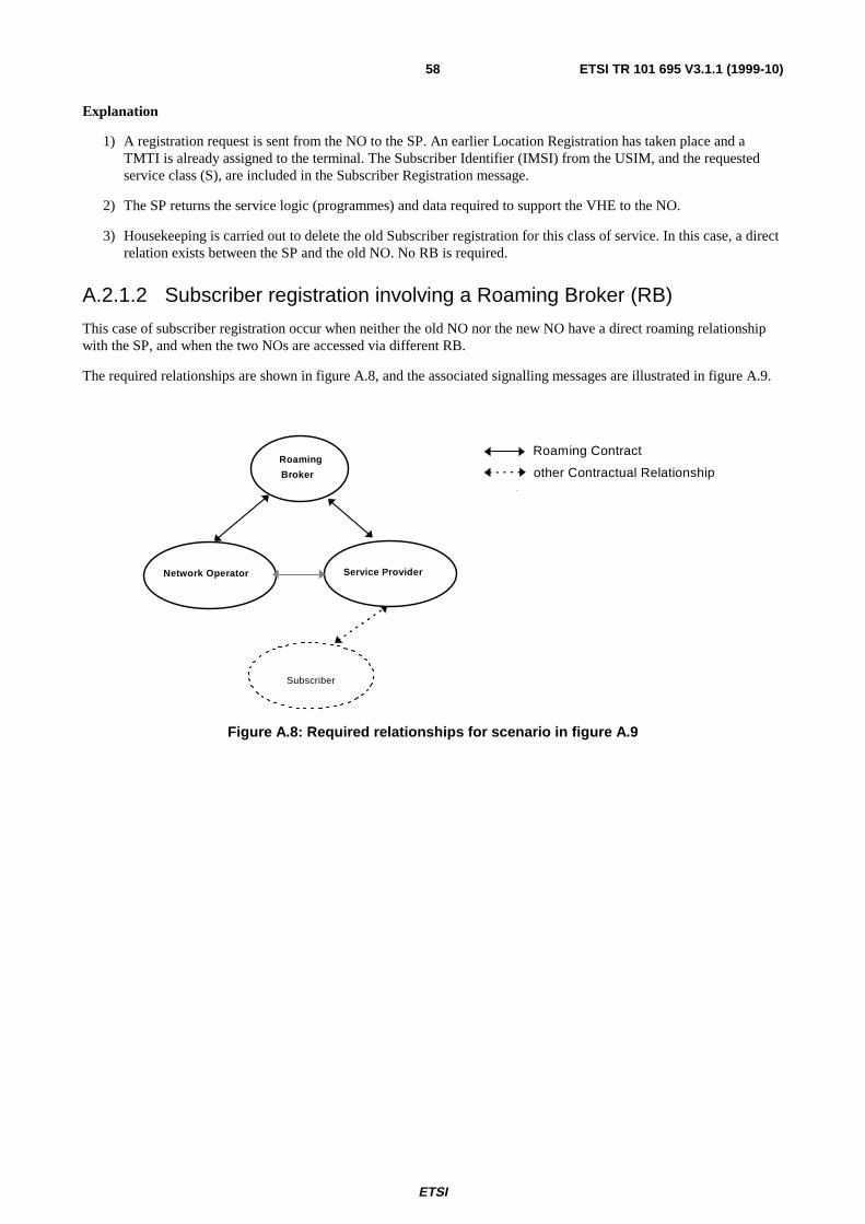
ETSI
ETSI TR 101 695 V3.1.1 (1999-10)58
Explanation
1) A registration request is sent from the NO to the SP. An earlier Location Registration has taken place and aTMTI is already assigned to the terminal. The Subscriber Identifier (IMSI) from the USIM, and the requestedservice class (S), are included in the Subscriber Registration message.
2) The SP returns the service logic (programmes) and data required to support the VHE to the NO.
3) Housekeeping is carried out to delete the old Subscriber registration for this class of service. In this case, a directrelation exists between the SP and the old NO. No RB is required.
A.2.1.2 Subscriber registration involving a Roaming Broker (RB)
This case of subscriber registration occur when neither the old NO nor the new NO have a direct roaming relationshipwith the SP, and when the two NOs are accessed via different RB.
The required relationships are shown in figure A.8, and the associated signalling messages are illustrated in figure A.9.
Network Operator
Roaming
Broker
Subscriber
Roaming Contract
Service Provider
other Contractual Relationship
Figure A.8: Required relationships for scenario in figure A.9
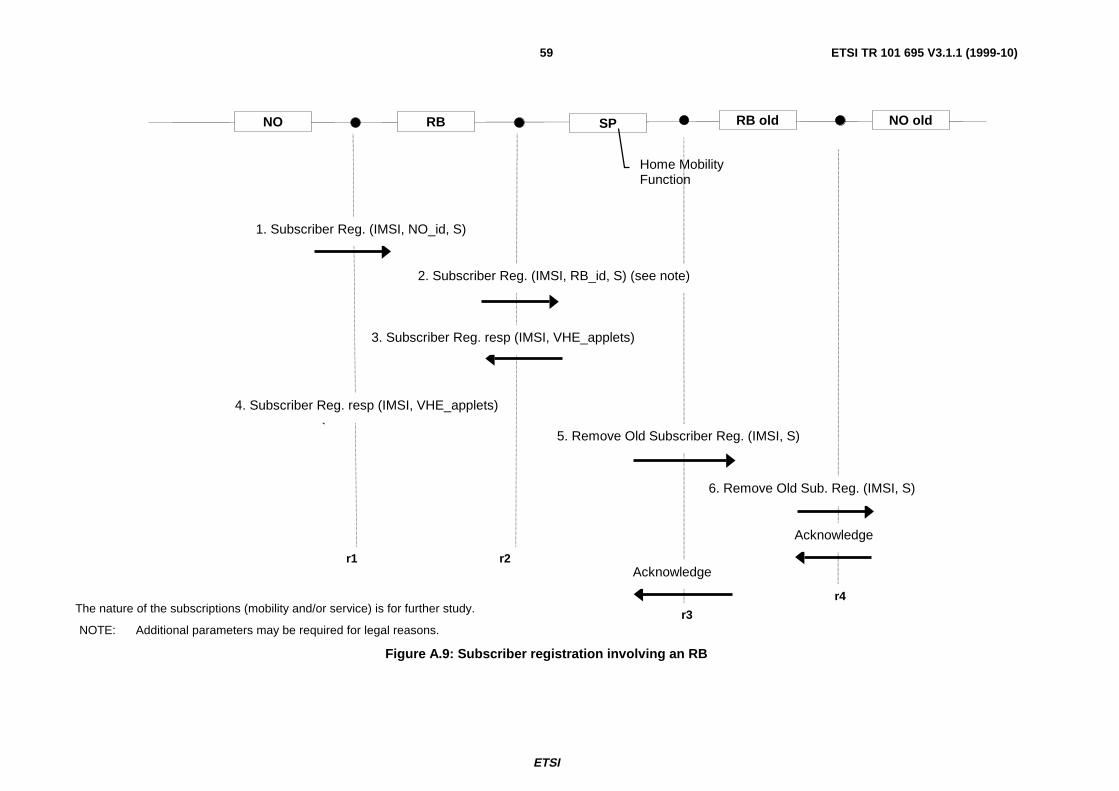
ETSI
ETSI TR 101 695 V3.1.1 (1999-10)59
The nature of the subscriptions (mobility and/or service) is for further study.
Figure A.9: Subscriber registration involving an RB
NO RB RB old NO oldSP
5. Remove Old Subscriber Reg. (IMSI, S)
1. Subscriber Reg. (IMSI, NO_id, S)
2. Subscriber Reg. (IMSI, RB_id, S) (see note)
6. Remove Old Sub. Reg. (IMSI, S)
Acknowledge
Acknowledge
3. Subscriber Reg. resp (IMSI, VHE_applets)
4. Subscriber Reg. resp (IMSI, VHE_applets)
r1 r2
r3
r4
NOTE: Additional parameters may be required for legal reasons.
Home MobilityFunction

ETSI
ETSI TR 101 695 V3.1.1 (1999-10)60
Explanation
1) The registration request is sent from the NO to the RB. An earlier Location Registration has taken place and aTMTI is already assigned to the terminal. The Subscriber Identifier (IMSI) from the USIM, and the requestedservice class (S), are included in the Subscriber Registration message.
2) The message is forwarded from the RB to the SP.
3) The SP returns the service logic (programmes) and data required to support the VHE to the RB.
4) The RB forwards the response to the NO.
5) Housekeeping is carried out to delete the old Subscriber registration for this class of service. It is assumed that nodirect relation exists between the SP and the old NO, and an RB is required (note the old RB may be differentfrom the new RB).
6) The housekeeping request is forwarded by the old RB to the old NO.
A.2.2 Subscriber registration procedure in the case where theHome Mobility function resides in the Network Operator role
A.2.2.1 Subscriber registration without Roaming Broker (RB) involved
A Roaming Broker (RB) is useful to facilitate roaming in a situation where many SPs and NOs exist. Nevertheless, evenin this situation some SP may have direct roaming agreements with some NOs, as this would simplify the procedures,allowing reduced signalling overhead; faster and less expensive procedures.
The following scenario illustrates how subscriber registration may be performed in the case where two NetworkOperators have a direct roaming agreement.
The required relationships are shown in figure A.10, and the associated signalling messages are illustrated infigure A.11.
Network Operator
Subscriber
Roaming Contract
Network Operator
other Contractual Relationship
Figure A.10: Required relationships for scenario in figure A.11

ETSI
ETSI TR 101 695 V3.1.1 (1999-10)61
Figure A.11: Subscriber registration without an RB involved
NO NO NO old
3. Remove Old Subscriber Reg. (IMSI, S)
1. Subscriber Reg. (IMSI, NO_id, S)
Acknowledge
2. Subscriber Reg. resp (IMSI, VHE_applets)
r1 r2
Home MobilityFunction

ETSI
ETSI TR 101 695 V3.1.1 (1999-10)62
Explanation
A registration request is sent from the Network Operator to the Network Operator where the Home Mobility function isresident. An earlier Location Registration has taken place and a TMTI is already assigned to the terminal. TheSubscriber Identifier (IMSI) from the USIM, and the requested service class (S), are included in the SubscriberRegistration message.
1) The Network Operator where the Home Mobility function is resident returns the service logic (programme) anddata required to support the VHE to the originating Network Operator.
2) Housekeeping is carried out to delete the old subscriber registration for this class of service. In this case, a directrelation exists between the Network Operator where the Home Mobility function is resident and the old NetworkOperator. No RB is required.
A.2.2.2 Subscriber registration involving a Roaming Broker (RB)
This case of Subscriber Registration occurs when neither the old Network Operator nor the new Network Operator havea direct roaming relationship with the Network Operator where the Home Mobility function resides, and both areaccessed via different Roaming Brokers.
The required relationships are shown in figure A.12, and the associated signalling messages are illustrated infigure A.13.
Network Operator
Roaming
Broker
Subscriber
Roaming Contract
Network Operator
other Contractual Relationship
Figure A.12: Required relationships for scenario in figure A.13

ETSI
ETSI TR 101 695 V3.1.1 (1999-10)63
The nature of the subscriptions (mobility and/or service) is for further study.
Figure A.13: Subscriber registration involving a Roaming Broker (RB)
NO RB RB old NO oldNO
5. Remove Old Subscriber Reg. (IMSI, S)
1. Subscriber Reg. (IMSI, NOv_id, S)
2. Subscriber Reg. (IMSI, RB_id, S) (see note)
6. Remove Old Sub. Reg. (IMSI, S)
Acknowledge
Acknowledge
3. Subscriber Reg. resp (IMSI, VHE_applets)
4. Subscriber Reg. resp (IMSI, VHE_applets)
r1 r2
r3
r4
NOTE: Additional parameters may be required for legal reasons.
Home MobilityFunction

ETSI
ETSI TR 101 695 V3.1.1 (1999-10)64
Explanation
1) The registration request is sent from the Network Operator to the RB. An earlier Location Registration has takenplace and a TMTI is already assigned to the terminal. The Subscriber Identifier (IMSI) from the USIM, and therequested service class (S), are included in the Subscriber Registration message.
2) The message is forwarded from the RB to the Network Operator where the Home Mobility function resides.
3) The Network Operator where the Home Mobility function resides returns the service logic (programme) and datarequired to support the VHE to the RB.
4) The RB forwards the response to the originating Network Operator.
5) Housekeeping is carried out to delete the old Subscriber registration for this class of service. It is assumed that nodirect relation exists between the Network Operator where the Home Mobility function resides and the oldNetwork Operator, and a RB is required (note the old RB may be different from the new RB).
6) The housekeeping request is forwarded by the old RB to the old Network Operator.
This subclause presents the existing VHE scenarios, as defined in subclause 6.2.
It shows the signalling needed for VHE between the UMTS actors defined in UMTS 22.01 [7].
Ia
II
Switching andTriggering
ServiceProvider
Home Logic Distribution
II
Ia
III
Service Logic Retrieval
Relay Home service
III
Processing Function
NetworkOperator
DataFunction
ProcessingFunction
Ib
Ib
Actual Home Service
Shared Service Control
Direct Home Command
V
IV
Ia
Ib
II
III
IV
V
Subscriber SP’s call controlelement
Figure A.14: The existing Service Transportability Scenarios
The Network Operator is composed of two main parts:
1) the Switching and Triggering part; and
2) the Processing Function.
The Service Provider is composed of a Data Function and a Processing Function. As noted in subclause 6.2, when objectmodelling techniques are employed, this separation of processing and data may not occur.
The scenarios are as described in subclause 6.2.

ETSI
ETSI TR 101 695 V3.1.1 (1999-10)65
A.3 VHE scenarios based on GSM MoU TG.25
A.3.1 Location registration procedure
A.3.1.1 Location registration involving a SNMP and RB
This case of Location Registration only occurs when:
1) There is NO contractual relationship between the SN and the HMP.
2) There is NO roaming relation between the SNMP and the HMP.
3) There is a contractual relationship between the SN and the SNMP.
4) There is a roaming relation between the RB and the SNMP and a roaming relation between the RB and the HMP.
5) There is a contractual relationship between the HMP and the SP.
6) There is NO contractual relationship between the SN in which the previous Subscriber (or Location) Registrationtook place and the HMP.
7) There is NO roaming relationship between the SNMP associated with the previous Subscriber (or Location)Registration and the HMP.
8) A different RB supported the previous Subscriber (Location) Registration.
This scenario necessitates the extensive signalling between the roles to allow the subscriber to be supported. It is ascenario, in which all roles must co-operate to provide a service, but only one RB is required. The required relationshipsare shown in figure A.15, and the associated signalling messages are illustrated in figure A.16.
Servin g Network
Serving Network
Roamin g
Broker
Home
Mobilit yProvider
Subscriber
Roaming Contract
Service ProviderMobilit y Provider
other Contractual Relationship
Figure A.15: Required relationships for scenario in figure A.16

ETSI
ETSI TR 101 695 V3.1.1 (1999-10)66
r5
SN SNMP RB HMP RB old SNMP old
SP
9. Remove Old Subscriber Reg. (IMSI, S)
1. Location Reg. (IMSI, LAI, S, TC )
2. Subscriber Reg. (IMSI, SNMP_id, S)
3. Subscriber Reg. (IMSI, RB_id, S) (see note)
4. Subscriber Reg. (IMSI, HMP_id, S)
5. Subscriber Reg. resp (IMSI, VHE_applets)
10. Remove Old Sub. Reg. (IMSI, S)
Acknowledge
Acknowledge
6. Subscriber Reg. resp (IMSI, VHE_applets)
7. Subscriber Reg. resp (IMSI, VHE_applets)
8. Location Reg. resp (TMSI, TMTI, VHE_applets)
r1r2 r3
r4
r6
NOTE: Additional parameters may be required for legal reasons.
The nature of the subscriptions (mobility and/or service) is for further study.
Figure A.16: Location registration involving an SNMP and RB

ETSI
ETSI TR 101 695 V3.1.1 (1999-10)67
A.3.1.1.1 Explanation of Location Registration involving an SNMP and RB
1) At r1, the message is sent from the SN to the SNMP because there is no direct relationship between the SN andthe HMP. As there is no permanent identifier assigned to the terminal, a temporary identifier must be assigned tothe terminal for the duration of the registration (the terminal looses the temporary identifier when the last user onthe terminal deregisters). The subscriber identifier (IMSI) from the USIM, the current location area (LAI), therequested service/Service Provider (S), and the terminal capabilities (TC) are included in the LocationRegistration message.
2) At r2, the message is relayed to the RB as there is no direct relationship between the SNMP and the HMP.
3) At r3, the message is sent from the RB to the HMP.
4) At r4, the message is sent to the appropriate SP. Note that in the case of multiple SPs, the HMP can use therequested service/Service Provider identifier (S) and the IMSI as a discriminator.
5) At r4, the SP returns the service logic (programs) and data required to support the VHE to the HMP.
6) At r3, the HMP forwards the response to the RB.
7) At r2, the RB forwards the response to the SNMP.
8) At r1, the SNMP forwards the response to the SN. This includes the temporary identifier which has been assignedto the terminal (TMTI) and the temporary identifier assigned to the user (TMSI).
9) At r5, housekeeping is carried out to delete the old Subscriber registration for this service. The general case isassumed, where no direct relation exists between the HMP and the old SNMP or SN), and a RB is required (notethe old RB may be different from the current RB).
10)At r6, the housekeeping request is forwarded by the old RB to the old SNMP.
It should be noted that there may be alternative approaches where the TMSI is assigned by the HMP duringauthentication of the USIM.
A.3.1.2 Location Registration (simple case)
A simple case of Location Registration only occurs when:
1) There is a contractual relationship between the SN and the HMP.
2) The previous Subscriber (Location) Registration did not involve a RB or a SNMP.
3) There is a contractual relationship between the HMP and the SP.
This scenario requires minimal signalling. The required relationships are shown in figure A.17 and the associatedsignalling messages are illustrated in the figure A.18.

ETSI
ETSI TR 101 695 V3.1.1 (1999-10)68
Home
Mobilit yProvider
Subscriber
Service Provider
Contractual Relationship
Serving Network
Figure A.17: Required relationships for scenario in figure A.18

ETSI
ETSI TR 101 695 V3.1.1 (1999-10)69
Figure A.18: Location Registration (simple case)
SN HMP
SP
1. Location Reg. (IMSI, LAI, S, TC)
2. Subscriber Reg. (IMSI, HMP_id, S)
3. Subscriber Reg. resp (IMSI, VHE_applets)
4. Location Reg. resp (TMSI, TMTI, VHE_applets)
r7 r4
ETSI
ETSI TR 101 695 V3.1.1 (1999-10)70
A.3.1.2.1 Explanation of Location Registration (simple case)
1) At r7, the message is sent from the SN to the HMP because there is a direct relation between the SN and the HMP.
2) At r4, the message is sent to the appropriate SP. Note that in the case of multiple SPs, the HMP can use the requested service/Service Provider identifier (S) and the IMSI as a discriminator.
3) At r4, the SP returns the service logic (program) and data required to support the VHE, to the HMP.
4) At r7, the assigned TMTI, TMSI and the service logic (program) and data required to support the VHE, are sent to the SN.
A.3.1.3 Combining roles
In everyday commercial practice, multiple roles will tend to be combined in one organization. This will allow signallingoverhead to be reduced and economies of scale to be achieved, with potential benefits to subscribers. At the same time,the fact that open interfaces are available will facilitate service expansion. For example, HMP and SP may be combinedin one organization, and in this case the interface specification at r4 may not be required. However, if the need arises toincrease the available services, then communication with an external SP can be achieved through standardized interfacesand the service resold.
The following scenario is introduced to illustrate how a GSM-like commercial model of the kind commonly found todaycan be supported in the future UMTS environment. This model assumes:
1) No RB is used.
2) The SN and SNMP roles are combined in a "Visited Network".
3) The SN, HMP and SP roles are combined in a "Home Network".
The associated signalling is shown in figure A.19.

ETSI
ETSI TR 101 695 V3.1.1 (1999-10)71
Figure A.19: Combining roles
SNMP / SNvisited HMP / SNhome SNMPold / SNold
3. Remove Old Subscriber Reg. (IMSI, S)
1. Location Reg. (IMSI, SN/SNMP_id,LAI, S, TC )
Acknowledge
2. Location Reg. resp (TMSI, TMTI, VHE_applets)
r r
"Visited Network""Home Network" Old "Visited Network"

ETSI
ETSI TR 101 695 V3.1.1 (1999-10)72
A.3.2 Subscriber Registration procedure
A.3.2.1 Subscriber Registration involving a SNMP and RB
This case of Subscriber Registration only occurs when:
1) There is NO contractual relationship between the SN and the HMP.
2) There is NO roaming relation between the SNMP and the HMP.
3) There is a contractual relationship between the SN and the SNMP.
4) There is a roaming relation between the RB and the SNMP and a roaming relation between the RB and the HMP.
5) There is a contractual relationship between the HMP and the SP.
6) There is NO contractual relationship between the SN in which the previous Subscriber (or Location) Registrationtook place and the HMP.
7) There is NO contractual relationship between the SNMP associated with the previous Subscriber (or Location)Registration and the HMP.
8) A different RB supported the previous Subscriber (Location) Registration.
This scenario necessitates extensive signalling between the roles to allow the subscriber to be supported. It is a scenario,in which all roles must co-operate to provide a service, but only one RB is required. It relates to the GSM MoU PRDTG.25 Scenario 3 for Location Registration and to Scenario 3 for support of the Virtual Home Environment (LocalSupport by Shadowing Home Services). The required relationships are shown in figure A.20, and the associatedsignalling messages are illustrated in figure A.21.
Servin g Network
Serving Network
Roamin g
Broker
Home
Mobilit yProvider
Subscriber
Roaming Contract
Service ProviderMobilit y Provider
other Contractual Relationship
Figure A.20: Required relationships for scenario in figure A.21

ETSI
ETSI TR 101 695 V3.1.1 (1999-10)73
SN SNMP RB HMP RB old SNMP old
SP
9. Remove Old Subscriber Reg. (IMSI, S)
1. Subscriber Reg. (IMSI, TMTI, S)
2. Subscriber Reg. (IMSI, SNMP_id, S)
3. Subscriber Reg. (IMSI, RB_id, S) (see note)
4. Subscriber Reg. (IMSI, HMP_id, S)
5. Subscriber Reg. resp (IMSI, VHE_applets)
10. Remove Old Sub. Reg. (IMSI, S)
Acknowledge
Acknowledge
6. Subscriber Reg. resp (IMSI, VHE_applets)
7. Subscriber Reg. resp (IMSI, VHE_applets)
8. Subscriber Reg. resp (TMSI, VHE_applets)
r1r2
r4
r5
r6
r3
NOTE: Additional parameters may be required for legal reasons.
The nature of the subscription (mobility and/or service ) is for further study.
Figure A.21: Subscriber Registration involving an SNMP and RB

ETSI
ETSI TR 101 695 V3.1.1 (1999-10)74
A.3.2.1.1 Explanation of Subscriber Registration involving an SNMP and RB
1) At r1, the message is sent from the SN to the SNMP because there is no direct relationship between the SN and the HMP. By the requirements for Subscriber Registration, an earlier Location Registration has taken place and a TMTI is already assigned to the terminal. The terminal identifier (TMTI), the Subscriber identifier (IMSI) from the USIM, and the requested service class (S), is included in the Subscriber Registration message.
2) At r2, the message is relayed to the RB as there is no direct relationship between the SNMP and the HMP.
3) At r3, the message is sent from the RB to the HMP.
4) At r4, the message is sent to the appropriate SP. Note that in the case of multiple SPs, the HMP can uses the service class (S) and the IMSI as a discriminator.
5) At r4, the SP returns the service logic (programs) and data required to support the VHE to the HMP.
6) At r3, the HMP forwards the response to the RB.
7) At r2, the RB forwards the response to the SNMP.
8) At r1, the SNMP forwards the response to the SN.
9) At r5, housekeeping is carried out to delete the old Subscriber registration for this class of service. The general case is assumed, where no direct relation exists between the HMP and the old SNMP or SN), and a RB is required (note the old RB may be different from the current RB).
10)At r6, the housekeeping request is forwarded by the old RB to the old SNMP.
It should be noted that there may be alternative approaches where the TMSI is assigned by the HMP duringauthentication of the USIM.
A.3.2.2 Subscriber Registration (Simple Case)
A simple case of Subscriber Registration only occurs when:
1) There is a contractual relationship between the SN and the HMP.
2) The previous Subscriber (Location) Registration did not involve a RB or a SNMP.
3) There is a contractual relationship between the HMP and the SP.
This scenario requires minimal signalling. The required relationships are shown in figure A.22 and the associatedsignalling messages are illustrated in figure A.23.
Home
MobilityProvider
Subscriber
Service Provider
Contractual Relationship
Serving Network
Figure A.22: Required relationships for scenario in figure A.23

ETSI
ETSI TR 101 695 V3.1.1 (1999-10)75
Figure A.23: Subscriber Registration (simple case)
SN HMP
SP
1. Subscriber Reg. (IMSI, TMTI, S)
2. Subscriber Reg. (IMSI, HMP_id, S)
3. Subscriber Reg. resp (IMSI, VHE_applets)
4. Subscriber Reg. resp (TMSI, VHE_applets)
r7 r4
ETSI
ETSI TR 101 695 V3.1.1 (1999-10)76
A.3.2.2.1 Explanation of Subscriber Registration (simple case)
1) At r7, the message is sent from the SN to the HMP because there is a direct relation between the SN and the HMP.
2) At r4, the message is sent to the appropriate SP. Note that in the case of multiple SP's, the HMP can use the service class (S) and the IMSI as a discriminator.
3) At r4, the SP returns the service logic (programs) and data required to support the VHE, to the HMP.
4) At r7, the assigned TMSI and the service logic (programs) and data required to support the VHE, are sent to the SN.
A.3.2.3 Combining roles
In everyday commercial practice, multiple roles will tend to be combined in one organization. This will allow signallingoverhead to be reduced and economies of scale to be achieved, with potential benefits to subscribers. At the same time,the fact that open interfaces are available will facilitate service expansion. For example, HMP and SP may be combinedin one organization, and in this case the interface specification at r4 may not be required. However, if the need arises toincrease the available services, then communication with an external SP can be achieved through standardized interfacesand the service resold.
The following scenario is introduced to illustrate how a GSM-like commercial model of the kind commonly found todaycan be supported in the future UMTS environment. This model assumes:
1) No RB is used.
2) The SN and SNMP roles are combined.
3) The HMP and SP roles are combined.
The associated signalling is shown in figure A.24.

ETSI
ETSI TR 101 695 V3.1.1 (1999-10)77
Figure A.24: Combining roles
SN / SNMP HMP/ SP SN/ SNMP old
3. Remove Old Subscriber Reg. (IMSI, S)
1. Subscriber Reg. (IMSI, SN/SNMP_id, S)
Acknowledge
2. Subscriber Reg. resp (IMSI, VHE_applets)
r8 r9
"VLR " "HLR" Old "VLR"

ETSI
ETSI TR 101 695 V3.1.1 (1999-10)78
A.4 Service provision scenarios based on GSM MoUTG.25
A.4.1 The roaming role modelThe essential features of the roaming role model are contained in GSM MoU TG 25.
A.4.2 Requirements and assumptionsThe following requirements have been identified for the application of the GSM MoU TG.25 Roaming Role Model forUMTS to a Multi-Service Provider environment:
- the UMTS Mobility Management Role player should be capable of interfacing to many Service Providers;
- the Services offered by those Service Providers have to be delivered to the UMTS user in the way specified bythe user's contractual agreement with each service provider.
Network architectures and information flows should be developed that are consistent with these requirements.
A.4.3 Generic information flowsThis subclause describes generic information flows for the implementation of advanced UMTS services in aMulti-Service Provider environment.

ETSI
ETSI TR 101 695 V3.1.1 (1999-10)79
A.4.3.1 Information flows for incoming call attempt with call screening
SP/VASP1
Incomingcall
Signalincoming
call
SP actionexecuted
Check ifSP actionrequired
ExecutePIN
bypassservice
DisconnectSP
RequestDisconnectSP/VASP
Connectbearerto SP
RequestConnectbearer toSP/VASP
connect touser
roamingnumber
Requestconnect to
calleduser
RequestDisconnect
SP
SP/VASP2SN HMP
Figure A.25: Incoming call presentation with call screening

ETSI
ETSI TR 101 695 V3.1.1 (1999-10)80
A.4.3.2 Information flows for terminal busy condition
Unable toconnect -terminal
busy
Unable toconnect -terminal
busyCheck ifSP actionrequired
RequestConnectbearer toSP/VASP
SP actionexecuted
Executevoicemail
service
Cleardowncall
Connectbearer toSP/VASP
SP/VASP1 SP/VASP2HMPSN
Figure A.26: Incoming call presentation with terminal busy condition
A.4.4 ConclusionsThe previous example shows a strong need for the Mobility Provider to be able to decide on Service Provider actions ina way that is consequential on call state. There obviously needs to be a close coupling between the call state machineand the Mobility Provider. This mechanism and how this is applied to Service Provider selection needs further study.

ETSI
ETSI TR 101 695 V3.1.1 (1999-10)81
History
Document history
V3.1.1 October 1999 Publication
ISBN 2-7437-3430-2Dépôt légal : Octobre 1999