Embed Size (px)
Citation preview
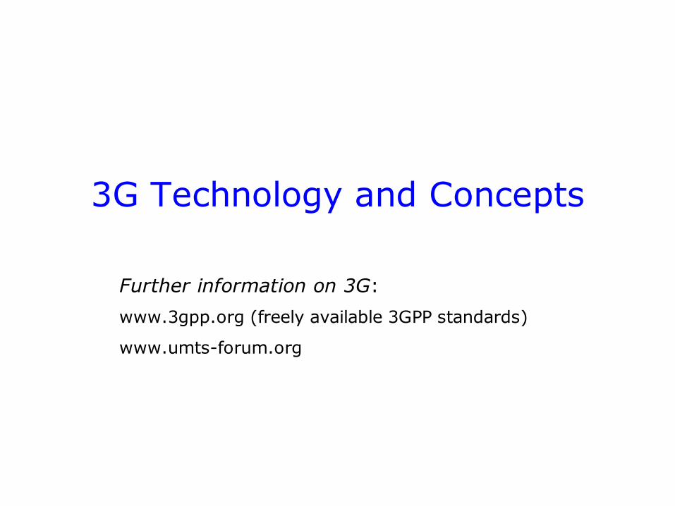
3G Technology and Concepts
Further information on 3G:
www.3gpp.org (freely available 3GPP standards)
www.umts-forum.org
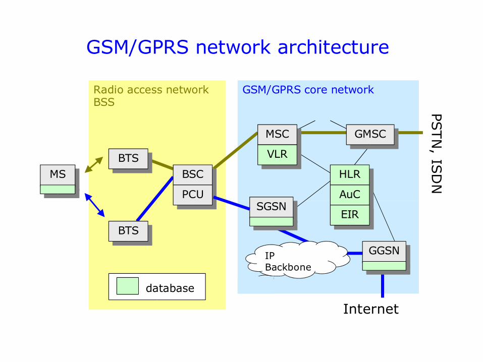
GSM/GPRS network architecture
GSM/GPRS core networkRadio access networkBSS
database
IP Backbone
Internet
PSTN
, ISD
N
BTS
BTS
BSC
MSC
VLR
SGSN
GMSC
HLR
AuC
EIR
GGSN
MS
PCU
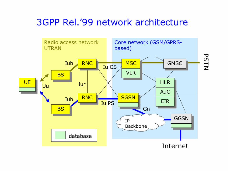
3GPP Rel.’99 network architecture
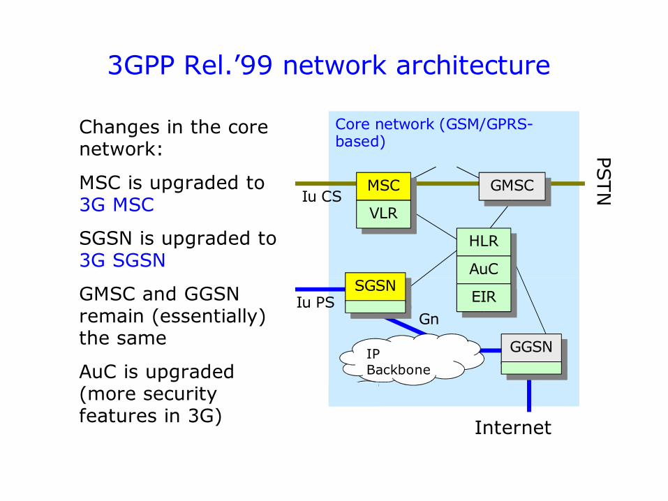
Core network (GSM/GPRS-based)
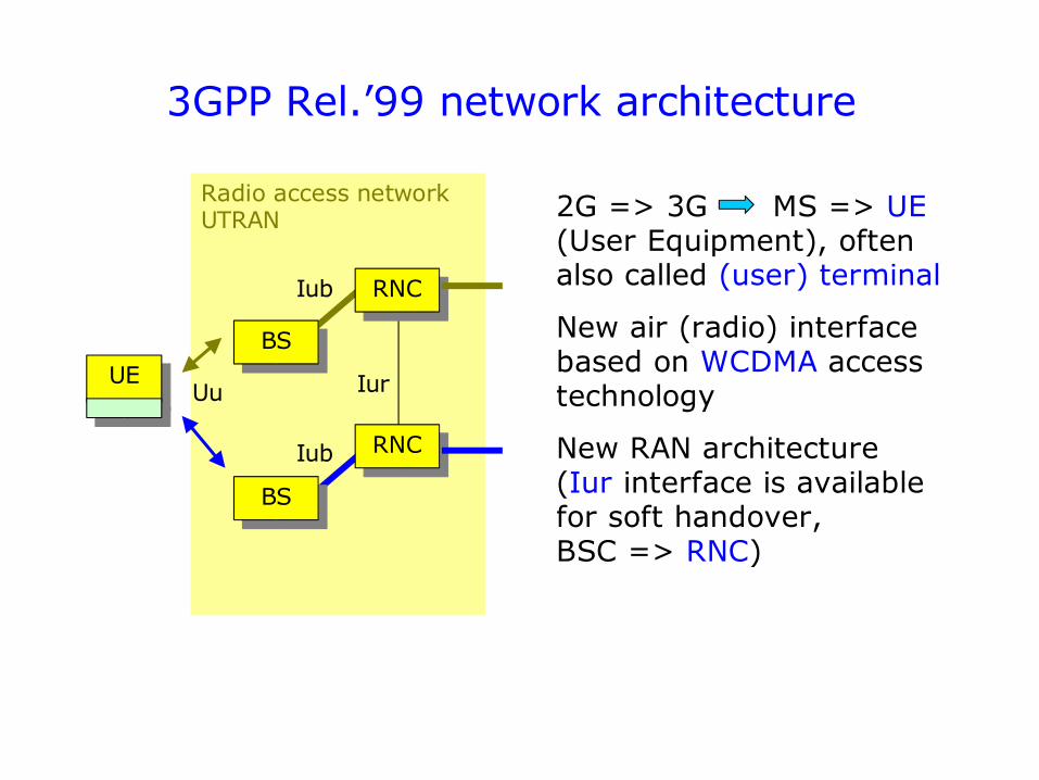
Radio access networkUTRAN
UE
Iu CS
Iur
Iub
Uu
GnIu PS
database
IP Backbone
Internet
PSTN
BS
BS
RNC
RNC
MSC
VLR
SGSN
GMSC
HLR
AuC
EIR
GGSN
Iub
3GPP Rel.’99 network architecture
Radio access networkUTRAN
UE Iur
Iub
Uu
BS
BS
RNC
RNC
Iub
2G => 3G MS => UE (User Equipment), often also called (user) terminal
New air (radio) interface based on WCDMA access technology
New RAN architecture(Iur interface is available for soft handover,BSC => RNC)
3GPP Rel.’99 network architecture
Core network (GSM/GPRS-based)
Iu CS
GnIu PS
IP Backbone
Internet
PSTNMSC
VLR
SGSN
GMSC
HLR
AuC
EIR
GGSN
Changes in the core network:
MSC is upgraded to 3G MSC
SGSN is upgraded to 3G SGSN
GMSC and GGSN remain (essentially) the same
AuC is upgraded (more security features in 3G)
3GPP Rel.4 network architecture
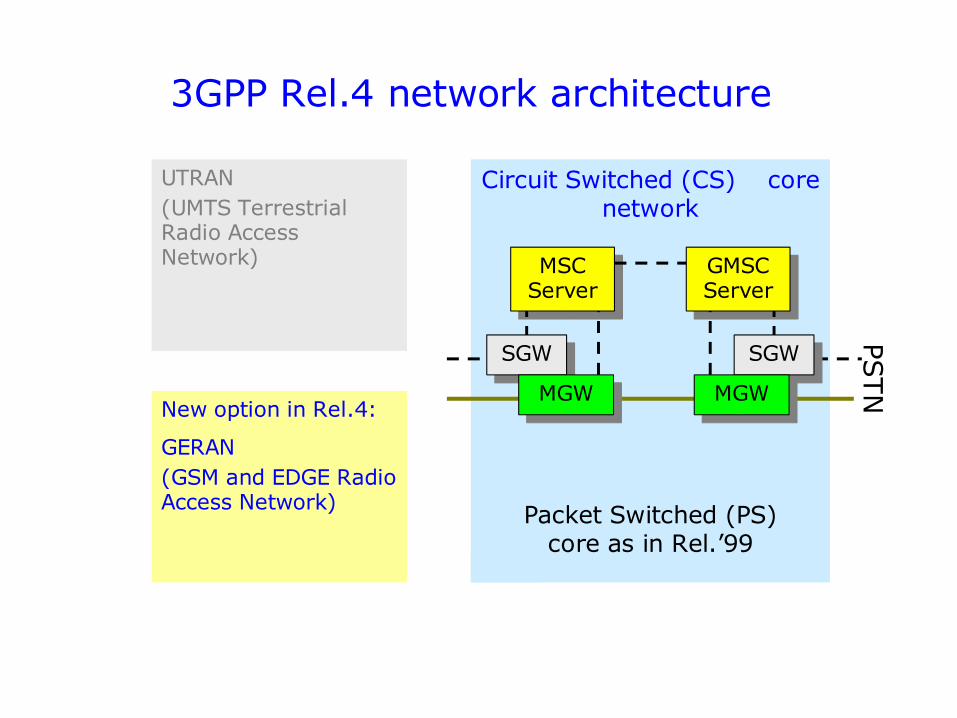
Circuit Switched (CS) core network
UTRAN(UMTS Terrestrial Radio Access Network)
PSTN
MSC Server
New option in Rel.4:
GERAN(GSM and EDGE Radio Access Network) Packet Switched (PS)
core as in Rel.’99
GMSC Server
SGW
MGW
SGW
MGW
3GPP Rel.4 network architecture
Circuit Switched (CS) core network
PSTN
MSC Server
GMSC Server
SGW
MGW
SGW
MGW
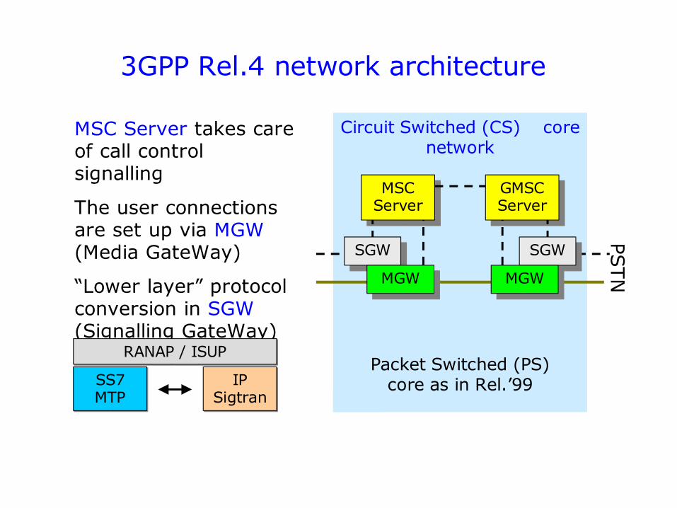
MSC Server takes care of call control signalling
The user connections are set up via MGW (Media GateWay)
“Lower layer” protocol conversion in SGW (Signalling GateWay)
RANAP / ISUP
SS7 MTP
IP Sigtran
Packet Switched (PS) core as in Rel.’99
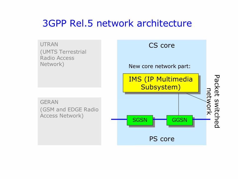
3GPP Rel.5 network architecture
CS core
SGSN GGSN
PS core
UTRAN(UMTS Terrestrial Radio Access Network)
GERAN(GSM and EDGE Radio Access Network)
New core network part:
Packet sw
itched
netw
ork
IMS (IP Multimedia Subsystem)
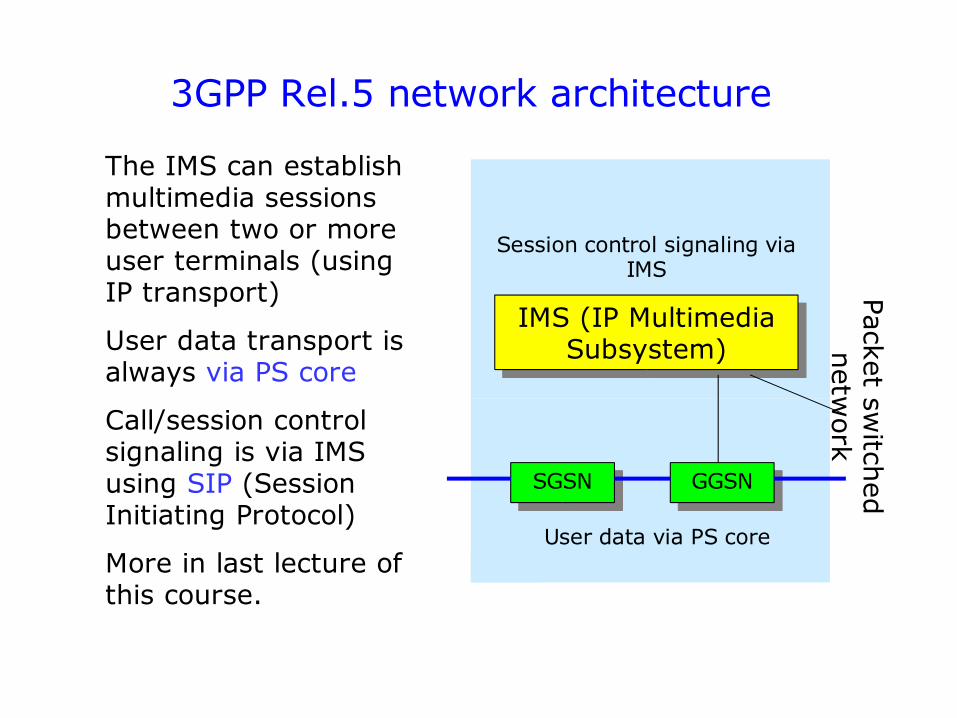
3GPP Rel.5 network architecture
SGSN GGSN
User data via PS core
The IMS can establish multimedia sessions between two or more user terminals (using IP transport)
User data transport is always via PS core
Call/session control signaling is via IMS using SIP (Session Initiating Protocol)
More in last lecture of this course.
Packet sw
itched
netw
ork
IMS (IP Multimedia Subsystem)
Session control signaling via IMS
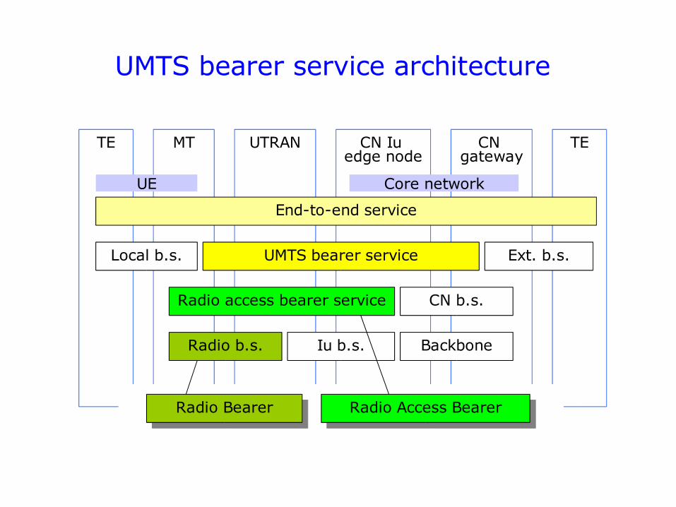
UMTS bearer service architecture
TE MT UTRAN CN Iu edge node
TECN gateway
End-to-end service
UMTS bearer service
Radio access bearer service CN b.s.
Local b.s. Ext. b.s.
Radio b.s. Iu b.s. Backbone
Radio Access BearerRadio Bearer
UE Core network
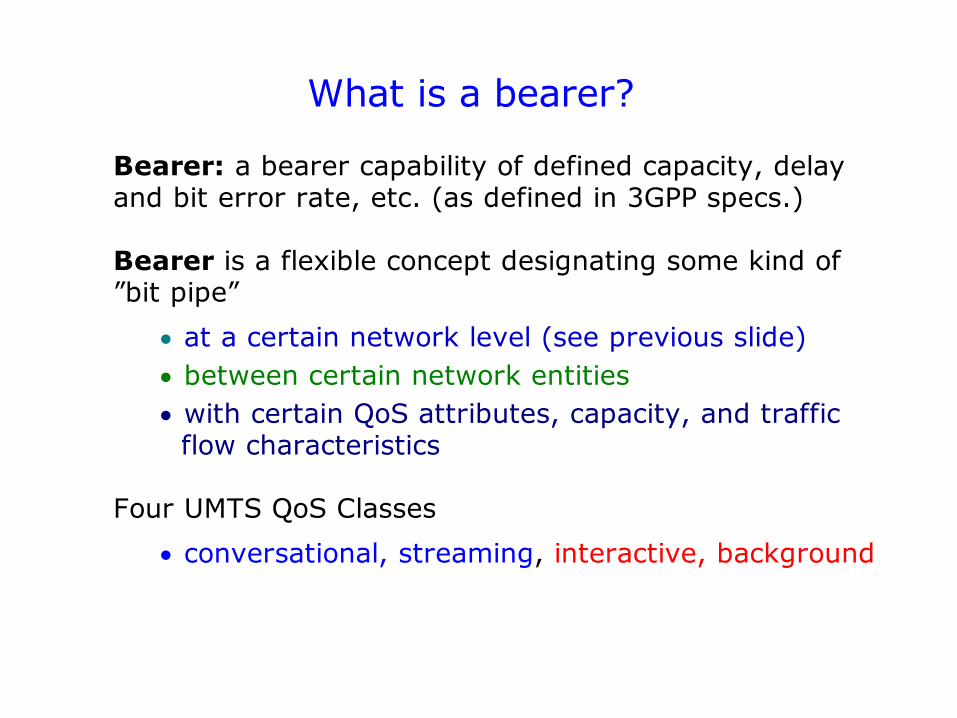
What is a bearer?
Bearer: a bearer capability of defined capacity, delay and bit error rate, etc. (as defined in 3GPP specs.)
Bearer is a flexible concept designating some kind of ”bit pipe”
at a certain network level (see previous slide) between certain network entities with certain QoS attributes, capacity, and traffic flow characteristics
Four UMTS QoS Classes
conversational, streaming, interactive, background
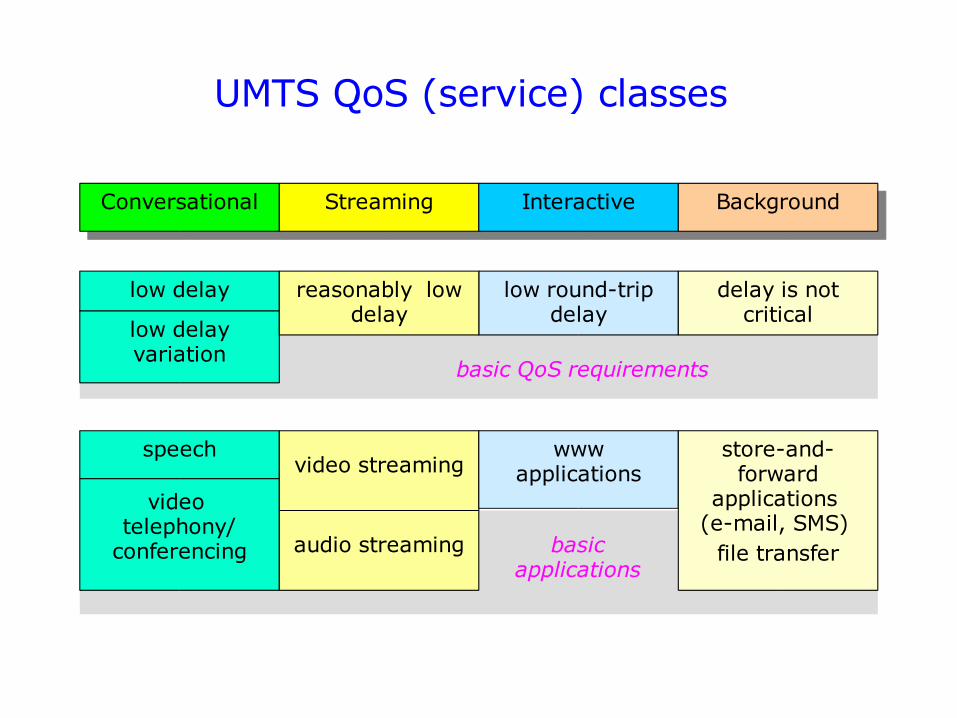
UMTS QoS (service) classes
Conversational Streaming Interactive Background
low delay
low delay variation
video telephony/
conferencing
speechvideo streaming
audio streaming
low round-trip delay
www applications
delay is not critical
store-and- forward
applications (e-mail, SMS)
file transfer
reasonably low delay
basic applications
basic QoS requirements
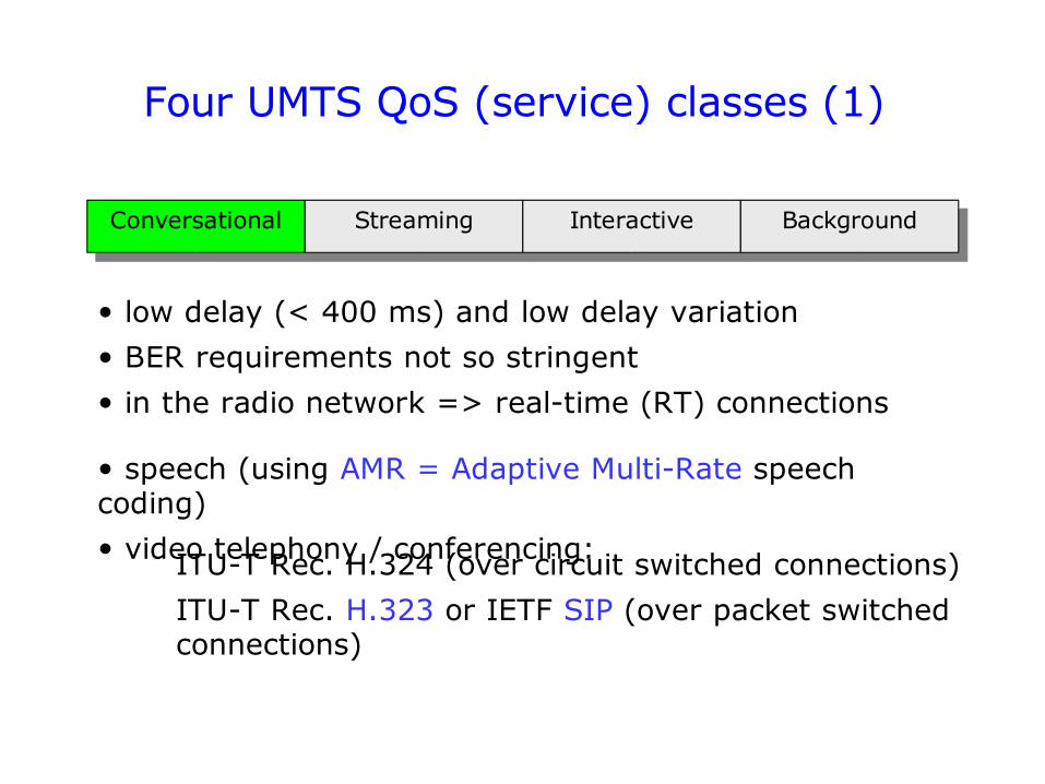
Four UMTS QoS (service) classes (1)
Conversational Streaming Interactive Background
• speech (using AMR = Adaptive Multi-Rate speech coding)
• video telephony / conferencing:ITU-T Rec. H.324 (over circuit switched connections)
ITU-T Rec. H.323 or IETF SIP (over packet switched connections)
• low delay (< 400 ms) and low delay variation
• BER requirements not so stringent
• in the radio network => real-time (RT) connections
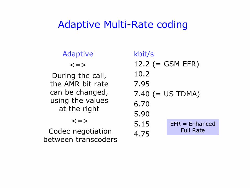
Adaptive Multi-Rate coding
kbit/s12.2 (= GSM EFR)10.27.957.40 (= US TDMA)6.705.905.154.75
Adaptive
<=>
During the call, the AMR bit rate can be changed, using the values
at the right
EFR = Enhanced Full RateCodec negotiation
between transcoders
<=>
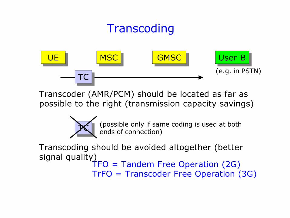
Transcoding
UE MSC GMSC User B
TC
Transcoder (AMR/PCM) should be located as far as possible to the right (transmission capacity savings)
TC
Transcoding should be avoided altogether (better signal quality)
TFO = Tandem Free Operation (2G)TrFO = Transcoder Free Operation (3G)
(possible only if same coding is used at both ends of connection)
(e.g. in PSTN)
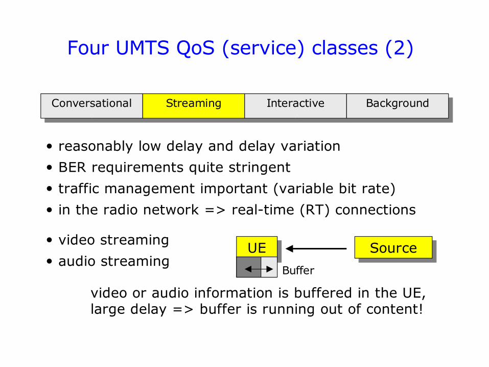
Four UMTS QoS (service) classes (2)
Conversational Streaming Interactive Background
• video streaming
• audio streaming
• reasonably low delay and delay variation
• BER requirements quite stringent
• traffic management important (variable bit rate)
• in the radio network => real-time (RT) connections
UE Source
video or audio information is buffered in the UE,large delay => buffer is running out of content!
Buffer
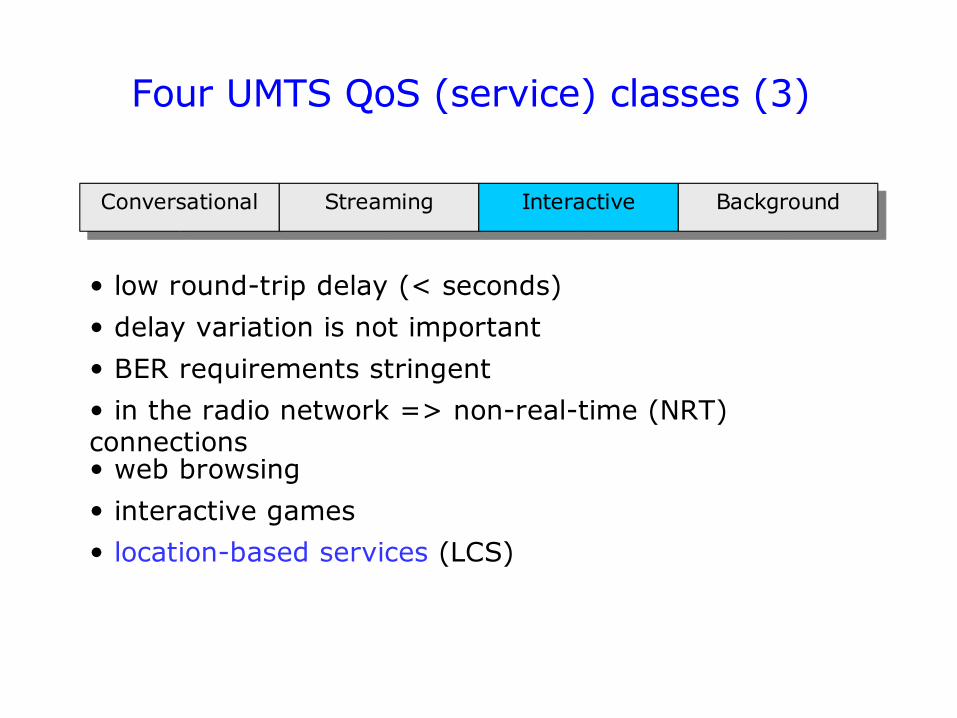
Four UMTS QoS (service) classes (3)
Conversational Streaming Interactive Background
• web browsing
• interactive games
• location-based services (LCS)
• low round-trip delay (< seconds)
• delay variation is not important
• BER requirements stringent
• in the radio network => non-real-time (NRT) connections
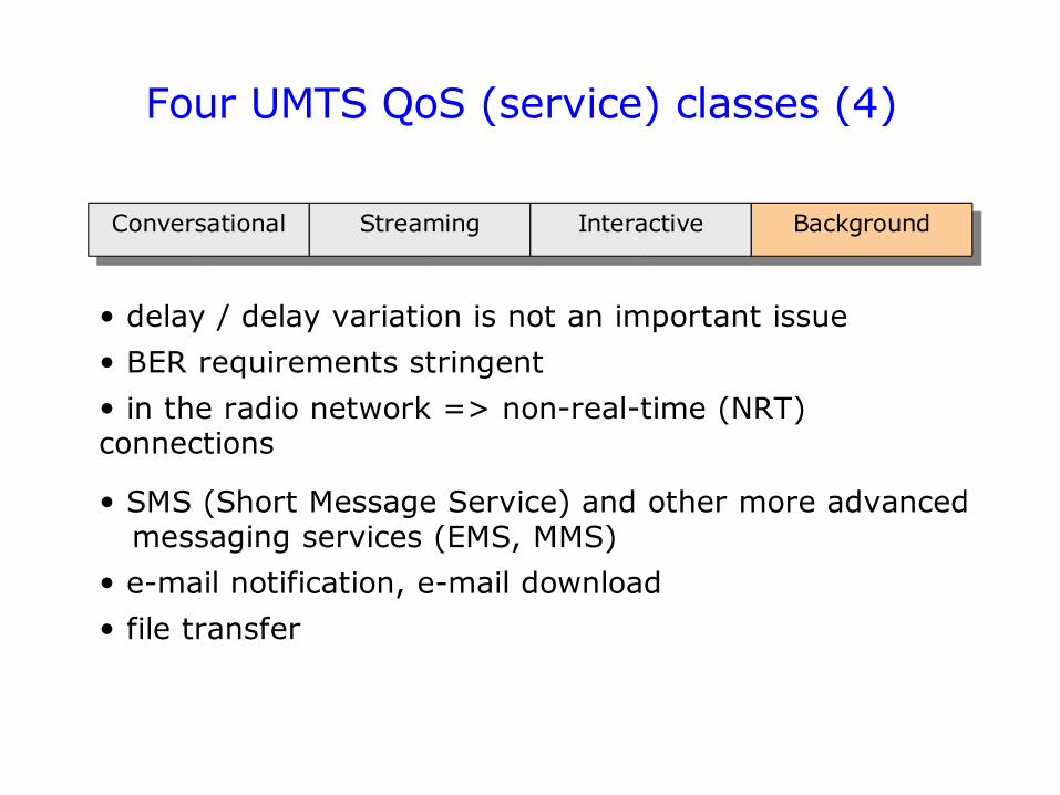
Four UMTS QoS (service) classes (4)
Conversational Streaming Interactive Background
• SMS (Short Message Service) and other more advanced messaging services (EMS, MMS)
• e-mail notification, e-mail download
• file transfer
• delay / delay variation is not an important issue
• BER requirements stringent
• in the radio network => non-real-time (NRT) connections
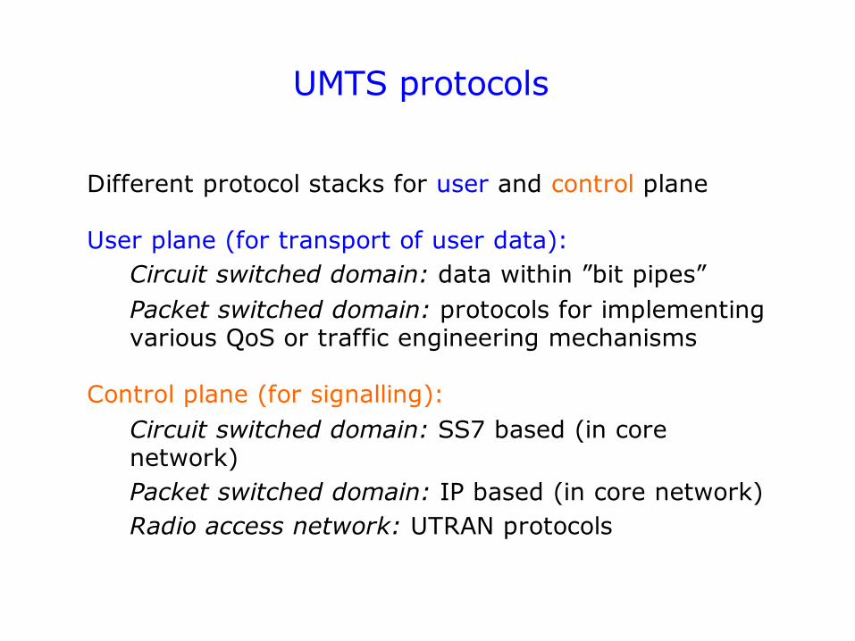
UMTS protocols
Different protocol stacks for user and control plane
User plane (for transport of user data): Circuit switched domain: data within ”bit pipes”Packet switched domain: protocols for implementing various QoS or traffic engineering mechanisms
Control plane (for signalling): Circuit switched domain: SS7 based (in core network)Packet switched domain: IP based (in core network)Radio access network: UTRAN protocols
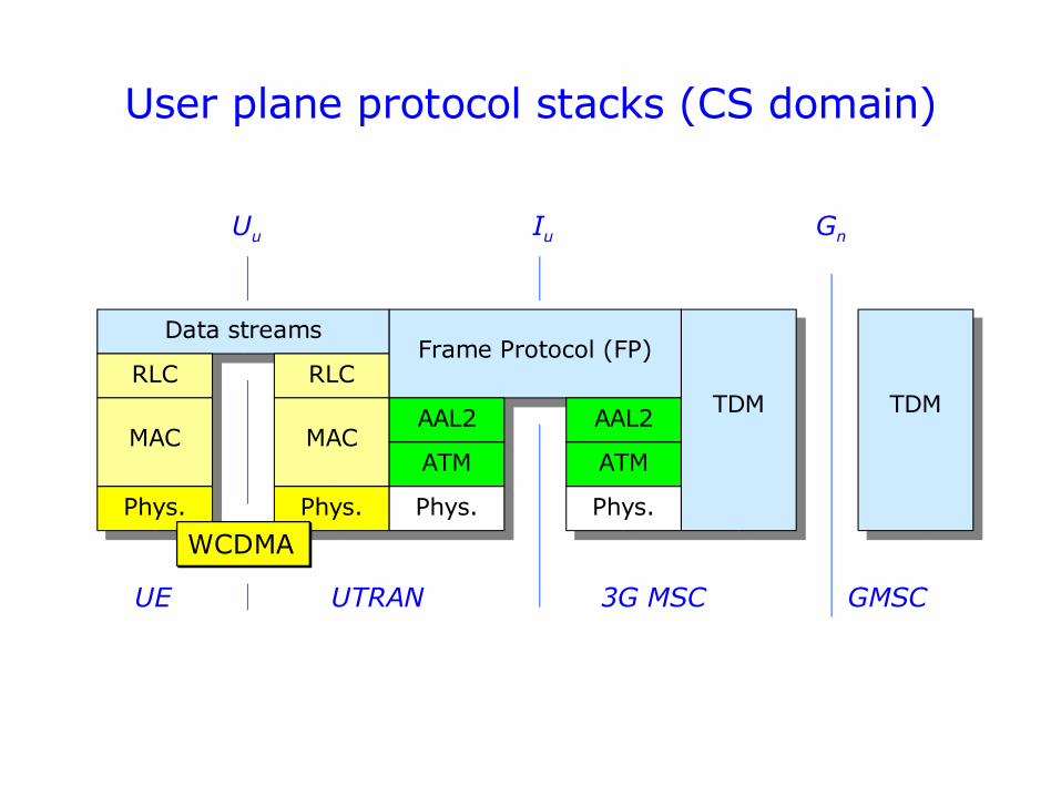
Data streams
RLC
MAC
Phys.
UE UTRAN 3G MSC GMSC
Uu Iu Gn
User plane protocol stacks (CS domain)
RLC
MAC
Phys.
WCDMA
TDM
Frame Protocol (FP)
AAL2
ATM
Phys.
AAL2
ATM
Phys.
TDM
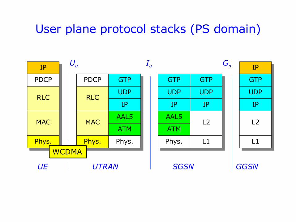
User plane protocol stacks (PS domain)
PDCP
RLC
GTP
UDP
IP
GTP
UDP
IP
IP IP
GTP
UDP
PDCP
RLC
MAC
Phys.
MAC
Phys.
AAL5
ATM
Phys.
AAL5
ATM
Phys.
IP
L2
L1
GTP
UDP
IP
L2
L1
UE UTRAN SGSN GGSN
Uu Iu Gn
WCDMA
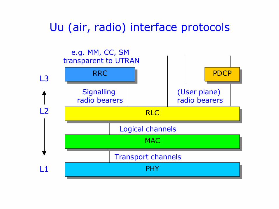
Uu (air, radio) interface protocols
PHY
MAC
RLC
RRC
Signalling radio bearers
(User plane) radio bearers
e.g. MM, CC, SM transparent to UTRAN
Logical channels
Transport channels
PDCPL3
L2
L1
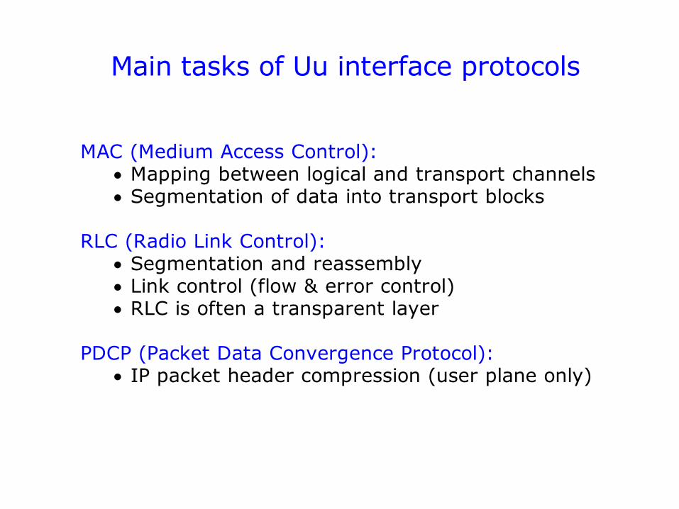
Main tasks of Uu interface protocols
MAC (Medium Access Control): Mapping between logical and transport channels Segmentation of data into transport blocks
RLC (Radio Link Control): Segmentation and reassembly Link control (flow & error control) RLC is often a transparent layer
PDCP (Packet Data Convergence Protocol): IP packet header compression (user plane only)
Main tasks of RRC protocol
Over the air interface, Radio Resource Control (RRC) messages carry all the relevant information required for setting up a Signalling Radio Bearer (during the lifetime of the RRC Connection) and setting up, modifying, and releasing Radio Bearers between UE and UTRAN (all being part of the RRC Connection).
RRC also participates in the co-ordination of other Radio Resource Management (RRM) operations, such as measurements and handovers.
In addition, RRC messages may carry in their payload higher layer signalling information (MM, CC or SM) that is not related to the air interface or UTRAN.
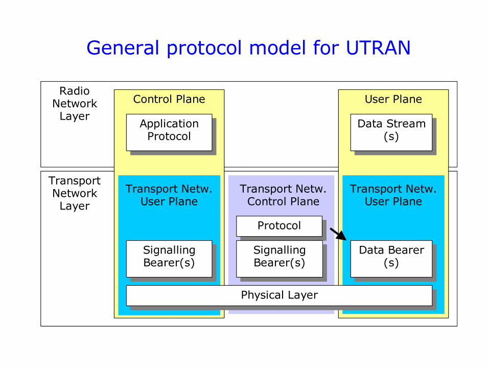
General protocol model for UTRAN
Radio Network Layer
Transport Network Layer
Control Plane User Plane
Transport Netw. Control Plane
Application Protocol
Data Stream(s)
Signalling Bearer(s)
Protocol
Data Bearer(s)
Transport Netw. User Plane
Transport Netw. User Plane
Signalling Bearer(s)
Physical Layer
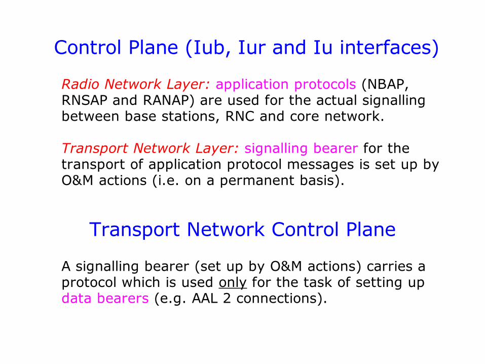
Control Plane (Iub, Iur and Iu interfaces)
Radio Network Layer: application protocols (NBAP, RNSAP and RANAP) are used for the actual signalling between base stations, RNC and core network.
Transport Network Layer: signalling bearer for the transport of application protocol messages is set up by O&M actions (i.e. on a permanent basis).
Transport Network Control Plane
A signalling bearer (set up by O&M actions) carries a protocol which is used only for the task of setting up data bearers (e.g. AAL 2 connections).
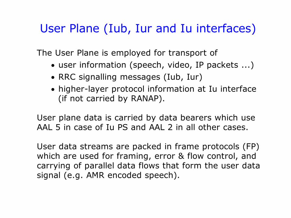
User Plane (Iub, Iur and Iu interfaces)
The User Plane is employed for transport of user information (speech, video, IP packets ...) RRC signalling messages (Iub, Iur) higher-layer protocol information at Iu interface
(if not carried by RANAP).
User plane data is carried by data bearers which use AAL 5 in case of Iu PS and AAL 2 in all other cases.
User data streams are packed in frame protocols (FP) which are used for framing, error & flow control, and carrying of parallel data flows that form the user data signal (e.g. AMR encoded speech).
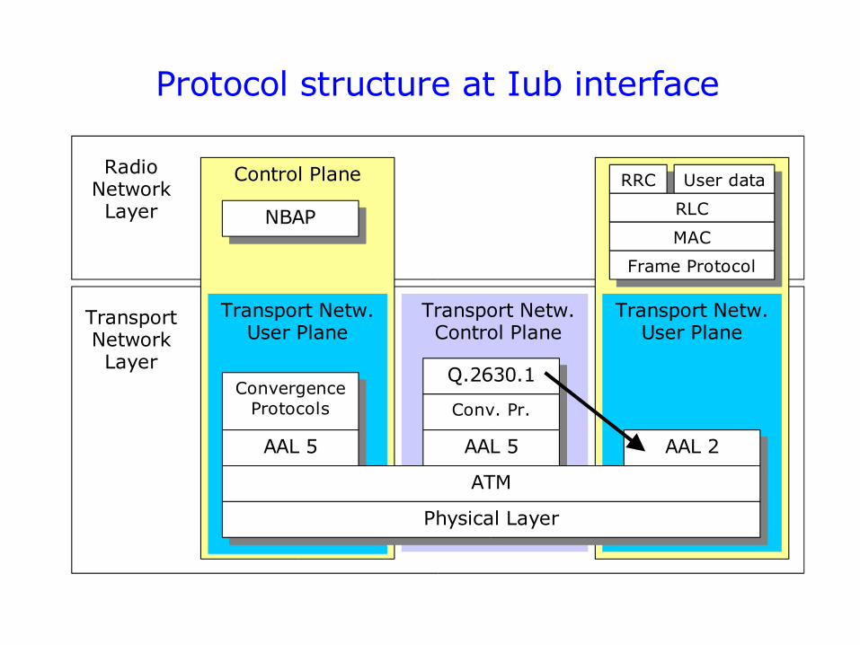
Protocol structure at Iub interface
Radio Network Layer
Transport Network Layer
Control Plane
Transport Netw. Control Plane
NBAP
Transport Netw. User Plane
Transport Netw. User Plane
Q.2630.1Convergence
Protocols
AAL 5
Conv. Pr.
AAL 5 AAL 2
ATM
Physical Layer
RRC User data
RLC
MAC
Frame Protocol

Control Plane
Transport Netw. Control Plane
RNSAP
Transport Netw. User Plane
Transport Netw. User Plane
Q.2630.1Convergence
Protocols
AAL 5
Conv. Pr.
AAL 5 AAL 2
ATM
Physical Layer
Protocol structure at Iur interface
Radio Network Layer
Transport Network Layer
RRC User data
RLC
MAC
Frame Protocol
Radio Network Layer
Transport Network Layer
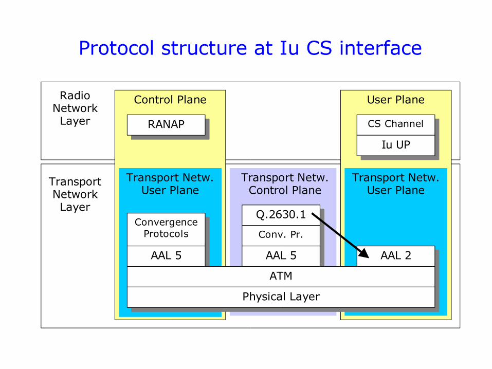
Control Plane User Plane
Transport Netw. Control Plane
RANAP
Transport Netw. User Plane
Transport Netw. User Plane
Q.2630.1Convergence
Protocols
AAL 5
Conv. Pr.
AAL 5
CS Channel
Iu UP
AAL 2
ATM
Physical Layer
Protocol structure at Iu CS interface
Radio Network Layer
Transport Network Layer
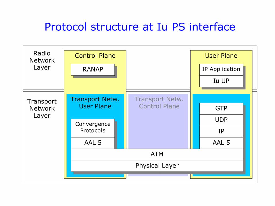
Control Plane User Plane
Transport Netw. Control Plane
RANAP
Transport Netw. User Plane
Convergence Protocols
AAL 5
IP Application
Protocol structure at Iu PS interface
GTP
UDP
IP
AAL 5
ATM
Physical Layer
Iu UP
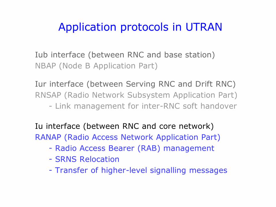
Application protocols in UTRAN
Iub interface (between RNC and base station)NBAP (Node B Application Part)
Iur interface (between Serving RNC and Drift RNC)RNSAP (Radio Network Subsystem Application Part)
- Link management for inter-RNC soft handover
Iu interface (between RNC and core network)RANAP (Radio Access Network Application Part)
- Radio Access Bearer (RAB) management- SRNS Relocation- Transfer of higher-level signalling messages
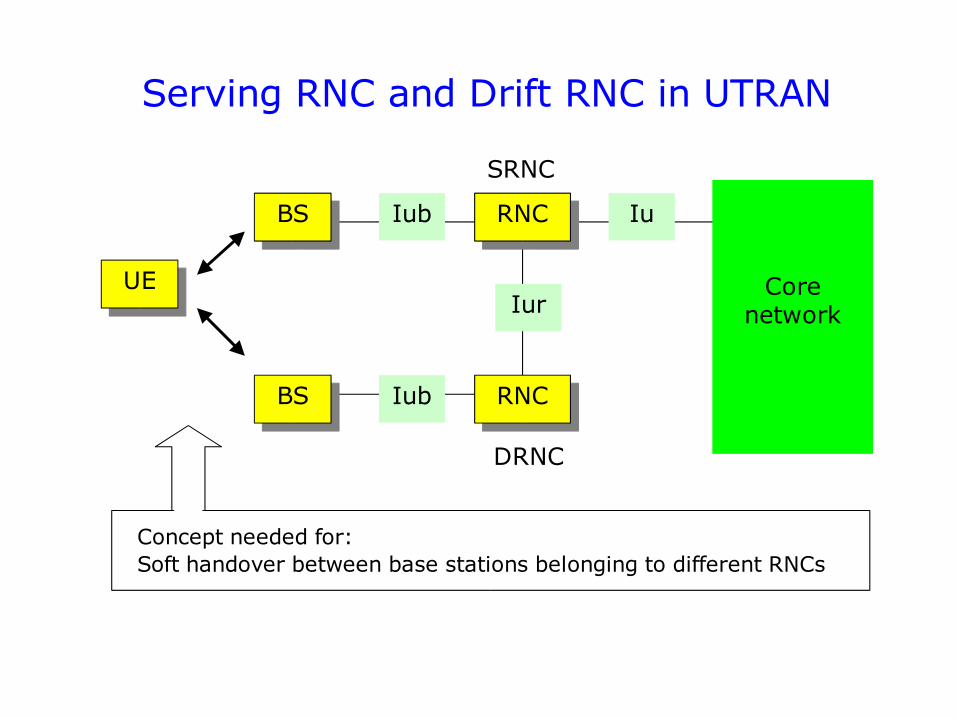
Serving RNC and Drift RNC in UTRAN
Core network
Iu
Iur
Iub
Iub
DRNC
SRNC
UE
BS
BS
RNC
RNC
Concept needed for:Soft handover between base stations belonging to different RNCs
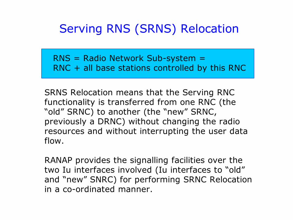
Serving RNS (SRNS) Relocation
RNS = Radio Network Sub-system = RNC + all base stations controlled by this RNC
SRNS Relocation means that the Serving RNC functionality is transferred from one RNC (the “old” SRNC) to another (the “new” SRNC, previously a DRNC) without changing the radio resources and without interrupting the user data flow.
RANAP provides the signalling facilities over the two Iu interfaces involved (Iu interfaces to “old” and “new” SNRC) for performing SRNC Relocation in a co-ordinated manner.
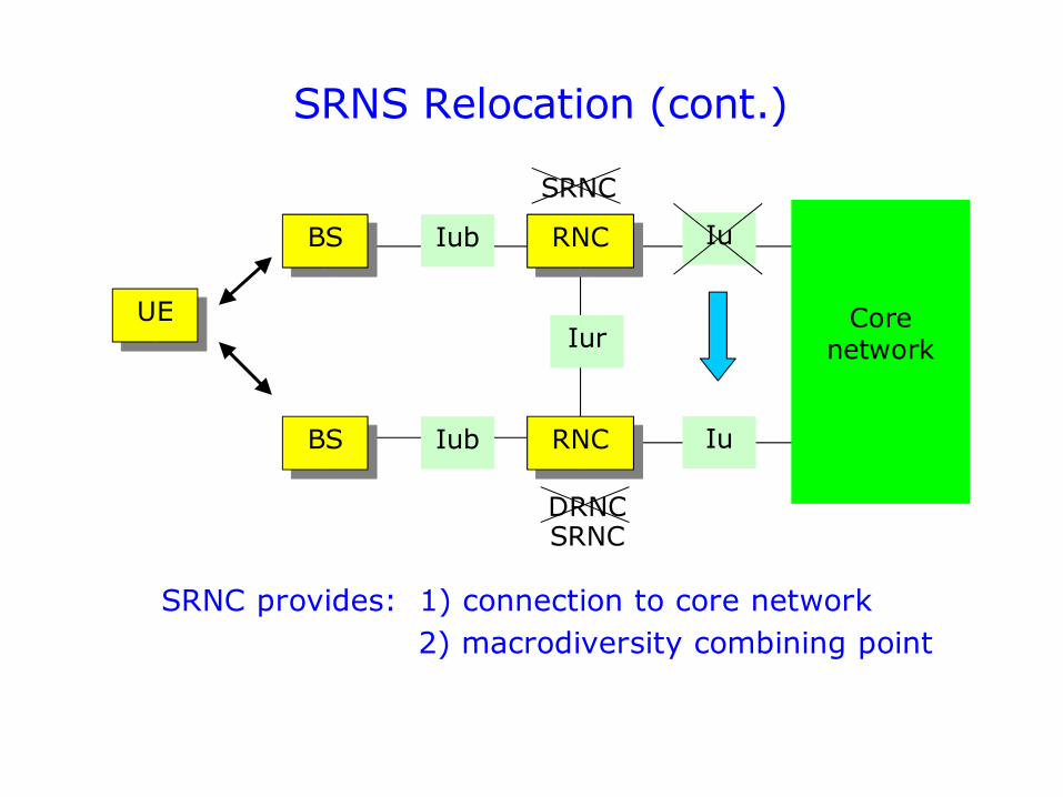
SRNS Relocation (cont.)
Core network
Iu
Iur
Iub
Iub
DRNC
SRNC
UE
BS
BS
RNC
RNC Iu
SRNC
SRNC provides: 1) connection to core network 2) macrodiversity combining point
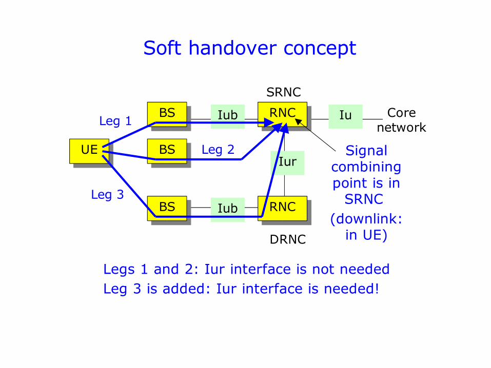
Soft handover concept
Iu
Iur
Iub
Iub
DRNC
SRNC
UE
BS
BS
RNC
RNC
Leg 1
Leg 3
Signal combining point is in
SRNC (downlink:
in UE)
BS Leg 2
Legs 1 and 2: Iur interface is not neededLeg 3 is added: Iur interface is needed!
Core network
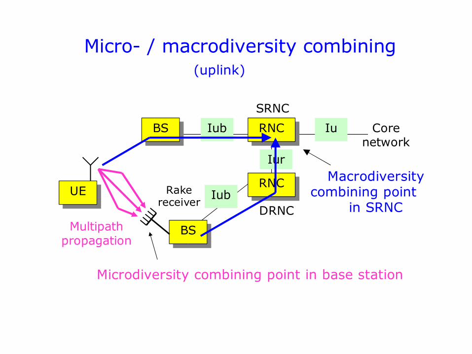
Micro- / macrodiversity combining
Iu
Iur
Iub
Iub
DRNC
SRNC
UE
BS
BS
RNC
RNC Macrodiversity combining point
in SRNC
Core network
Rake receiver
Multipath propagation
Microdiversity combining point in base station
(uplink)
Micro- / macrodiversity combining
Microdiversity combining: multipath signal components are processed in Rake “fingers” and combined using MRC (Maximum Ratio Combining)
Macrodiversity combining: the bit sequences received via different legs (and with different bit error positions) are combined at the SRNC (usually: selection combining = the best quality bit sequence is selected).
Hard handover: slow (a lot of signalling)
Soft handover: fast selection in SRNC
(uplink)
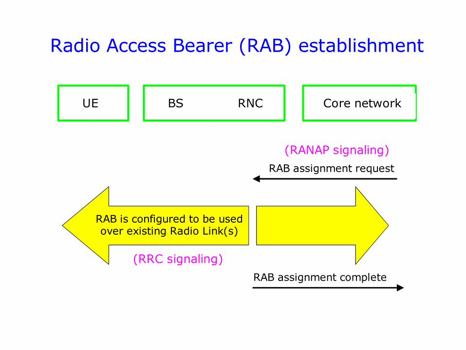
Radio Access Bearer (RAB) establishment
RAB assignment request
RAB assignment complete
RAB is configured to be used over existing Radio Link(s)
(RANAP signaling)
UE BS RNC
(RRC signaling)
Core network
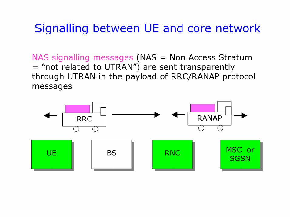
Signalling between UE and core network
UE BS RNC MSC orSGSN
RRC RANAP
NAS signalling messages (NAS = Non Access Stratum = “not related to UTRAN”) are sent transparently through UTRAN in the payload of RRC/RANAP protocol messages
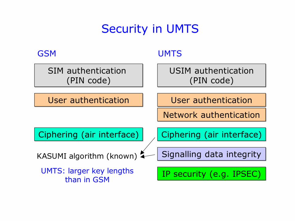
Security in UMTS
GSM UMTS
SIM authentication (PIN code)
User authentication
Ciphering (air interface)
Signalling data integrity
IP security (e.g. IPSEC)
User authentication
Network authentication
USIM authentication (PIN code)
Ciphering (air interface)
KASUMI algorithm (known)
UMTS: larger key lengths than in GSM
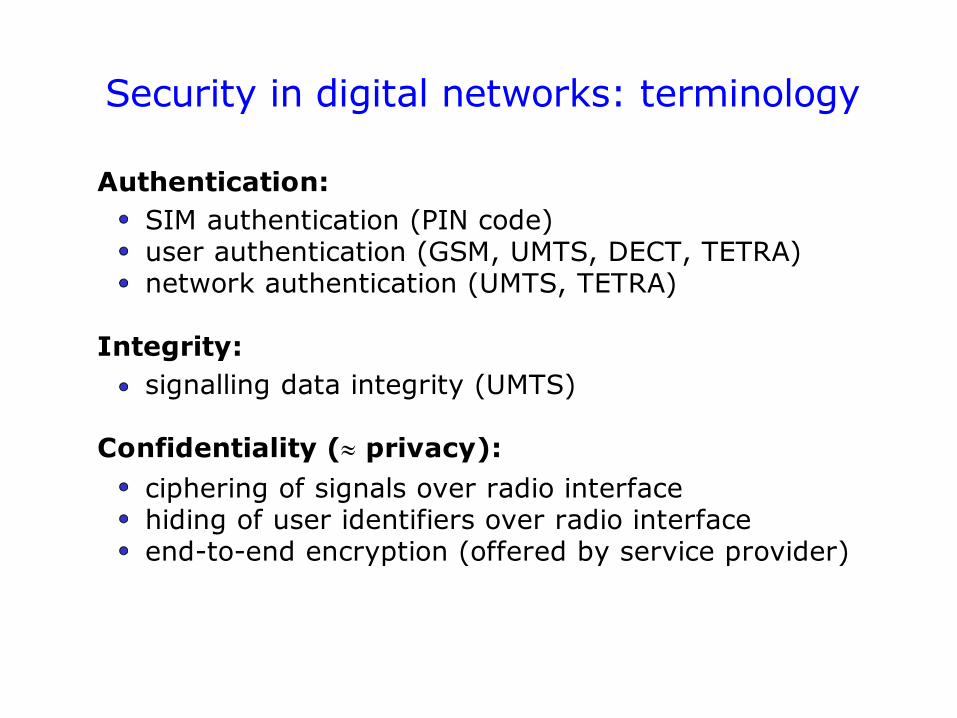
Security in digital networks: terminology
Authentication:SIM authentication (PIN code)user authentication (GSM, UMTS, DECT, TETRA)network authentication (UMTS, TETRA)
Integrity:signalling data integrity (UMTS)
Confidentiality ( privacy):
ciphering of signals over radio interfacehiding of user identifiers over radio interfaceend-to-end encryption (offered by service provider)
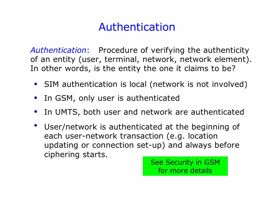
Authentication
Authentication: Procedure of verifying the authenticity of an entity (user, terminal, network, network element). In other words, is the entity the one it claims to be?
SIM authentication is local (network is not involved)
In GSM, only user is authenticated
In UMTS, both user and network are authenticated
User/network is authenticated at the beginning of each user-network transaction (e.g. location updating or connection set-up) and always before ciphering starts.
See Security in GSM for more details
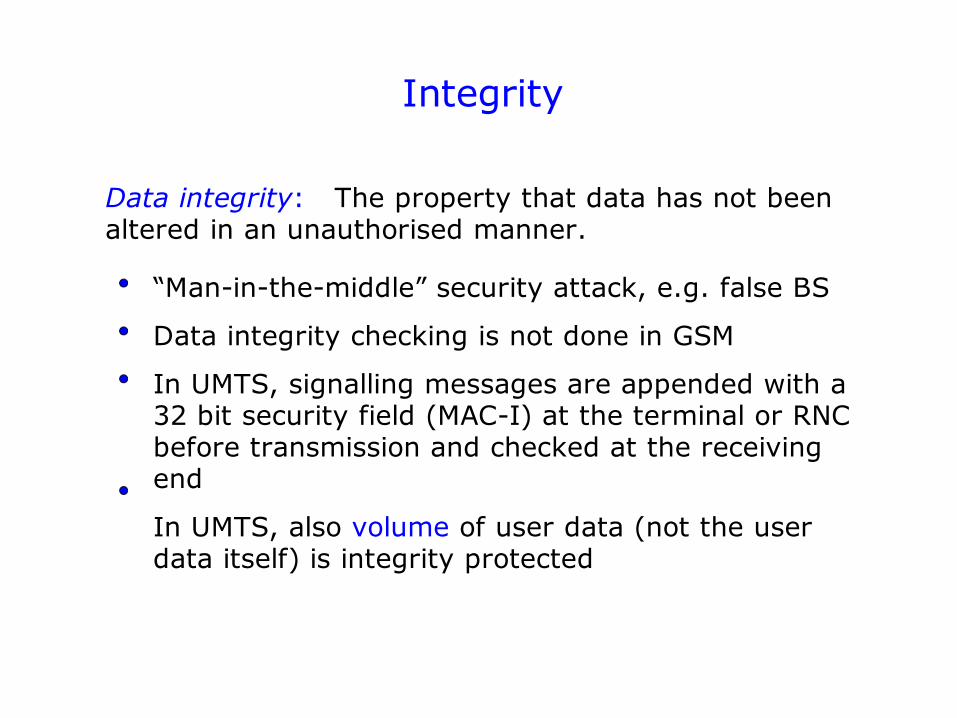
Integrity
Data integrity: The property that data has not been altered in an unauthorised manner.
“Man-in-the-middle” security attack, e.g. false BS
Data integrity checking is not done in GSM
In UMTS, signalling messages are appended with a 32 bit security field (MAC-I) at the terminal or RNC before transmission and checked at the receiving end
In UMTS, also volume of user data (not the user data itself) is integrity protected
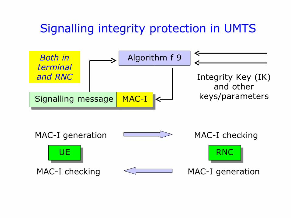
Signalling integrity protection in UMTS
Signalling message
Algorithm f 9
MAC-I
Integrity Key (IK) and other
keys/parameters
UE RNC
MAC-I generation MAC-I checking
MAC-I generationMAC-I checking
Both in terminal and RNC
Confidentiality
Confidentiality: The property that information is not made available to unauthorised individuals, entities or processes.
Example 1: Ciphering (encryption) over the air interface
Example 2: Preventing unencrypted transmission of user ID information such as IMSI number over the air interface
=> Temporary Mobile Subscriber Identity (TMSI) is generated (at the end of each MM or CM transaction) and is used at the beginning of the next transaction instead of IMSI.
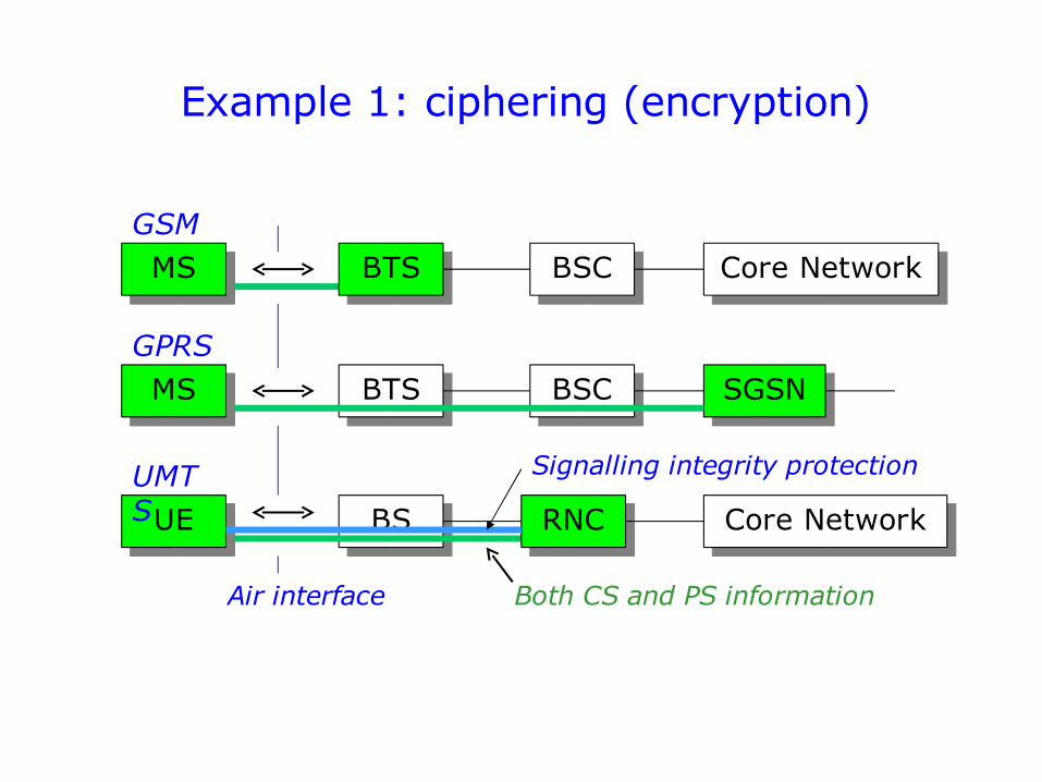
Example 1: ciphering (encryption)
BS
MS
UE
BTS BSC
RNC
SGSN
Core Network
Air interface
GPRS
UMTS
MS BTS BSC Core NetworkGSM
Both CS and PS information
Signalling integrity protection
WCDMA Technology … just some basic concepts
(not required knowledge in this course)
RLC RLC
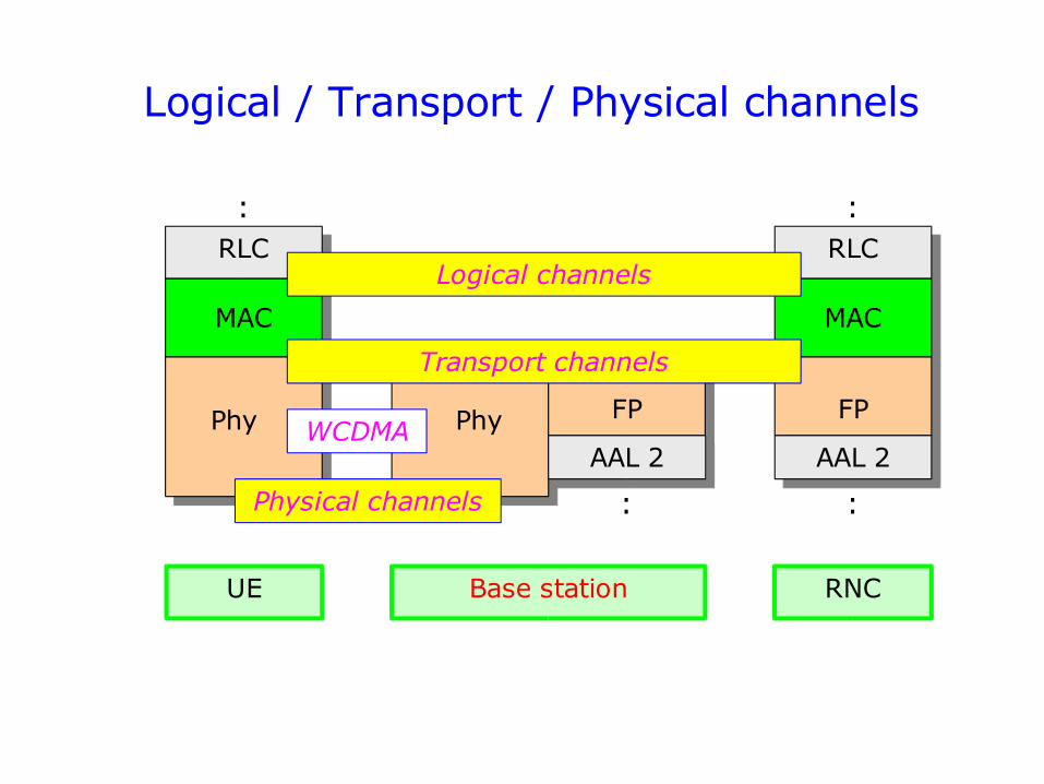
Logical / Transport / Physical channels
MAC
FP Phy FP
UE Base station RNC
AAL 2
MAC
AAL 2 Phy
Logical channels
Physical channels
Transport channels
: :
WCDMA
::
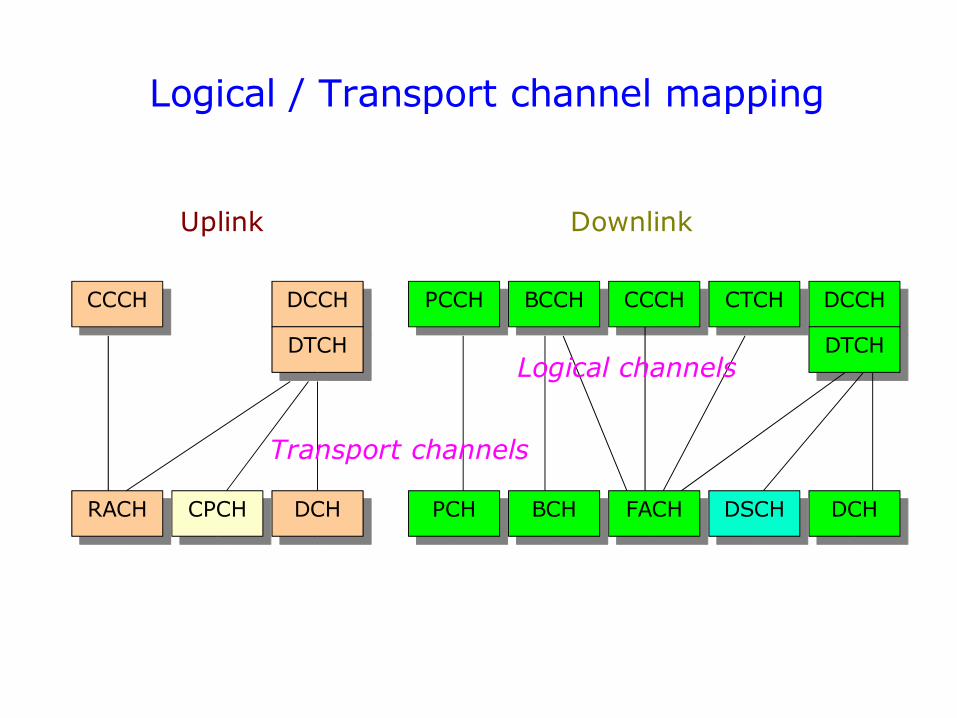
Logical / Transport channel mapping
CCCH DCCH
PCH DCHDSCHFACHBCHDCHCPCHRACH
DCCHCTCHCCCHBCCHPCCH
Uplink Downlink
DTCH DTCHLogical channels
Transport channels
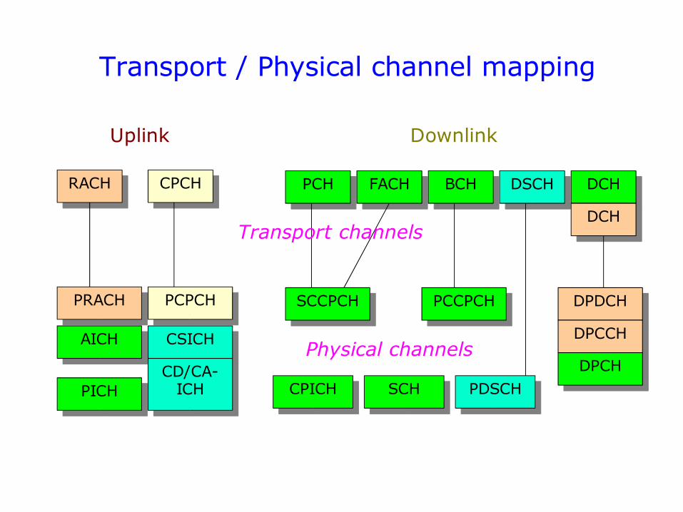
Transport / Physical channel mapping
PCH DCHDSCHFACH BCH
DCH
CPCHRACH
PRACH PCPCH SCCPCH PCCPCH DPDCH
DPCCH
SCHCPICH
AICH
PICH
CSICHPhysical channels
Transport channels
DPCHCD/CA-ICH
Uplink Downlink
PDSCH
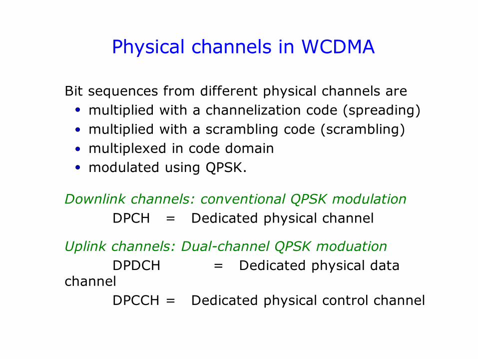
Physical channels in WCDMA
Bit sequences from different physical channels are multiplied with a channelization code (spreading) multiplied with a scrambling code (scrambling) multiplexed in code domain modulated using QPSK.
Downlink channels: conventional QPSK modulationDPCH = Dedicated physical channel
Uplink channels: Dual-channel QPSK moduationDPDCH = Dedicated physical data
channelDPCCH = Dedicated physical control channel
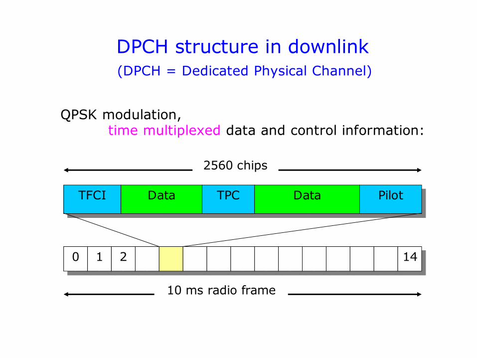
DPCH structure in downlink
TFCI Data TPC Data
10 ms radio frame
0 1 2 14
2560 chips
Pilot
QPSK modulation, time multiplexed data and control information:
(DPCH = Dedicated Physical Channel)
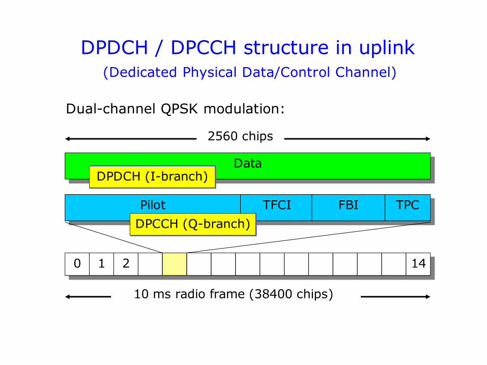
DPDCH / DPCCH structure in uplink(Dedicated Physical Data/Control Channel)
Data
Pilot TFCI FBI TPC
DPDCH (I-branch)
10 ms radio frame (38400 chips)
0 1 2 14
2560 chips
DPCCH (Q-branch)
Dual-channel QPSK modulation:
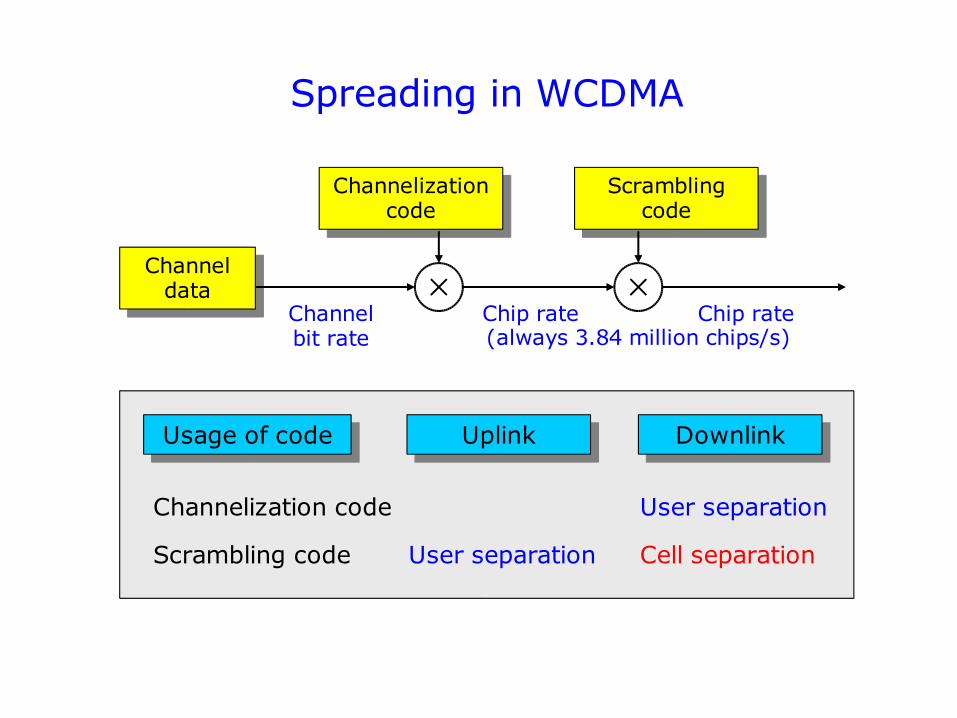
Spreading in WCDMA
Channel data
Channelization code
Scrambling code
Channel bit rate
Chip rate Chip rate
Usage of code Uplink Downlink
Channelization code
Scrambling code
User separation
User separation Cell separation
(always 3.84 million chips/s)
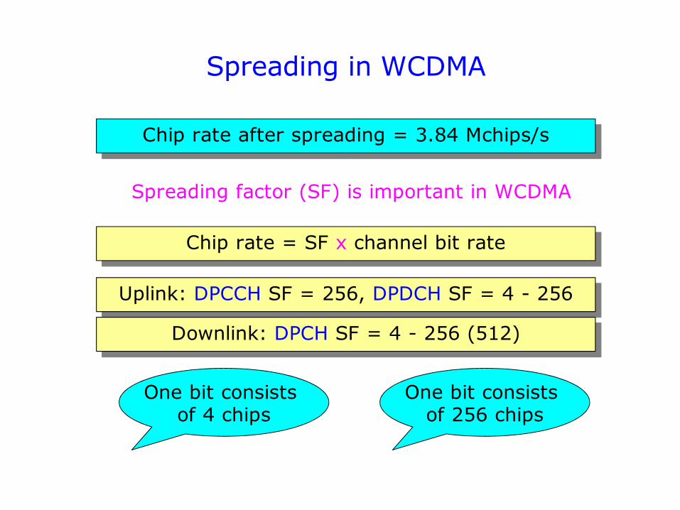
Spreading in WCDMA
Chip rate = SF x channel bit rate
Chip rate after spreading = 3.84 Mchips/s
Uplink: DPCCH SF = 256, DPDCH SF = 4 - 256
Downlink: DPCH SF = 4 - 256 (512)
Spreading factor (SF) is important in WCDMA
One bit consists of 256 chips
One bit consists of 4 chips
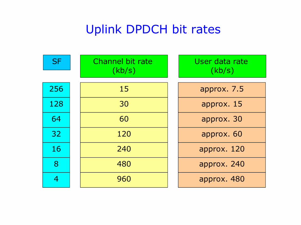
Uplink DPDCH bit rates
256
128
64
32
16
8
4
SF Channel bit rate (kb/s)
User data rate (kb/s)
15
30
60
120
240
480
approx. 7.5
approx. 15
approx. 30
approx. 60
approx. 120
approx. 240
960 approx. 480
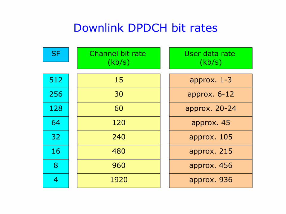
Downlink DPDCH bit rates
256
128
64
32
16
8
4
SF Channel bit rate (kb/s)
User data rate (kb/s)
15
30
60
120
240
480
approx. 1-3
approx. 6-12
approx. 20-24
approx. 45
approx. 105
approx. 215
960 approx. 456
512
1920 approx. 936
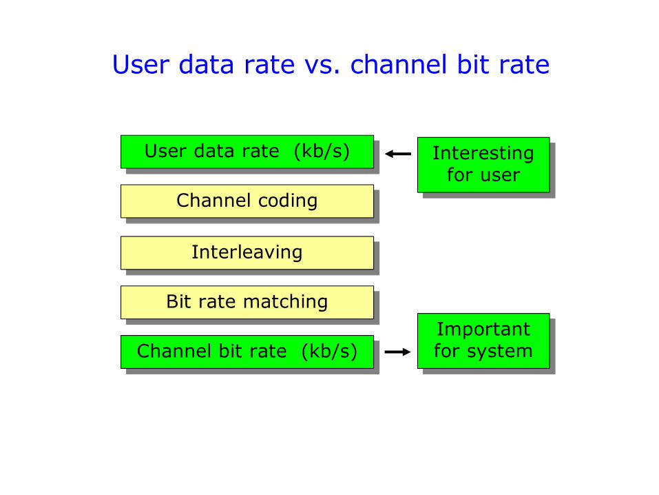
User data rate vs. channel bit rate
Channel bit rate (kb/s)
User data rate (kb/s)
Channel coding
Interleaving
Bit rate matching
Interesting for user
Important for system
Services for 3G (and partly 2G)… just some basic concepts
(not required knowledge in this course)
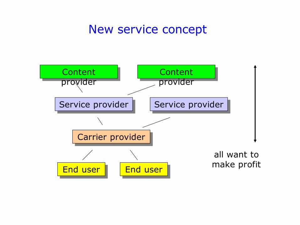
New service concept
End user End user
Carrier provider
Service provider Service provider
Content provider
Content provider
all want to make profit
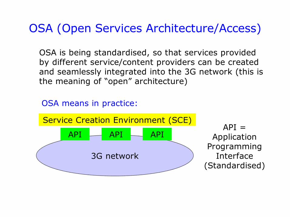
OSA is being standardised, so that services provided by different service/content providers can be created and seamlessly integrated into the 3G network (this is the meaning of “open” architecture)
OSA (Open Services Architecture/Access)
3G network
API API API
Service Creation Environment (SCE)API =
Application Programming
Interface (Standardised)
OSA means in practice:

CAMEL (Customised Applications for Mobile network Enhanced Logic) is a set of “IN” type functions and procedures that make operator-specific IN services available to subscribers who roam outside their home network.
CAMEL = IN technology + global mobility
CAMEL Service Environment (CSE) is a logical entity in the subscriber’s home network which processes IN related procedures
CSE SCP in home network
CAMEL (2G & 3G)
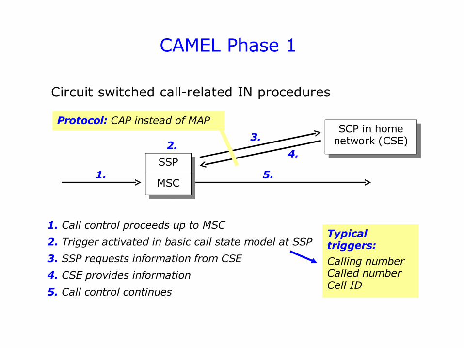
Circuit switched call-related IN procedures
CAMEL Phase 1
1. Call control proceeds up to MSC
SSP
MSC
SCP in home network (CSE)
1.
2.3.
4.
5.
2. Trigger activated in basic call state model at SSP
3. SSP requests information from CSE
4. CSE provides information
5. Call control continues
Typical triggers:
Calling numberCalled numberCell ID
Protocol: CAP instead of MAP
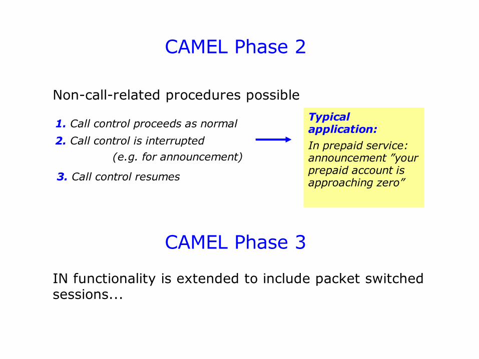
CAMEL Phase 2
Non-call-related procedures possible
1. Call control proceeds as normal
2. Call control is interrupted
3. Call control resumes
Typical application:
In prepaid service:announcement ”your prepaid account is approaching zero”
(e.g. for announcement)
IN functionality is extended to include packet switched sessions...
CAMEL Phase 3
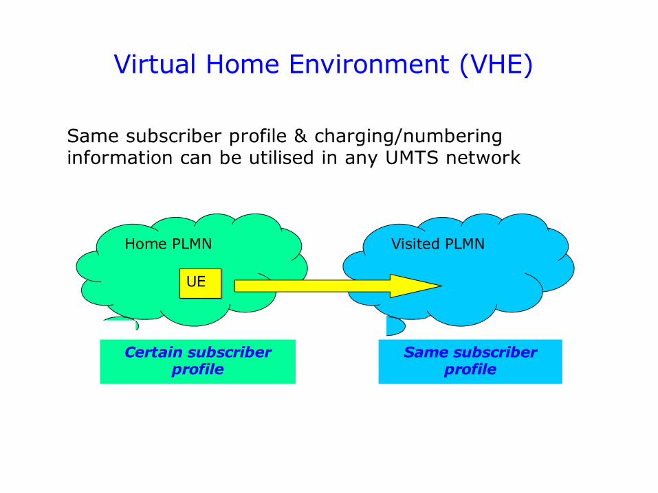
Virtual Home Environment (VHE)
Same subscriber profile & charging/numbering information can be utilised in any UMTS network
Home PLMN Visited PLMN
UE
Certain subscriber profile
Same subscriber profile
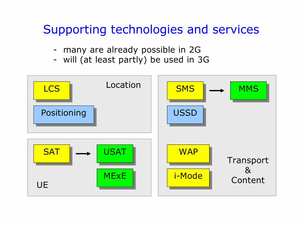
Supporting technologies and services
Positioning
SMS
USSD
MMSLCS
SAT USAT
MExE
WAP
Location
UE
Transport&
Contenti-Mode
- many are already possible in 2G - will (at least partly) be used in 3G
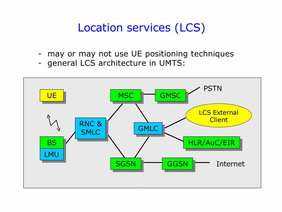
Location services (LCS)
- may or may not use UE positioning techniques- general LCS architecture in UMTS:
UEPSTN
Internet
BS
LMU
RNC & SMLC
MSC
GMLC
SGSN GGSN
HLR/AuC/EIR
GMSC
LCS External Client
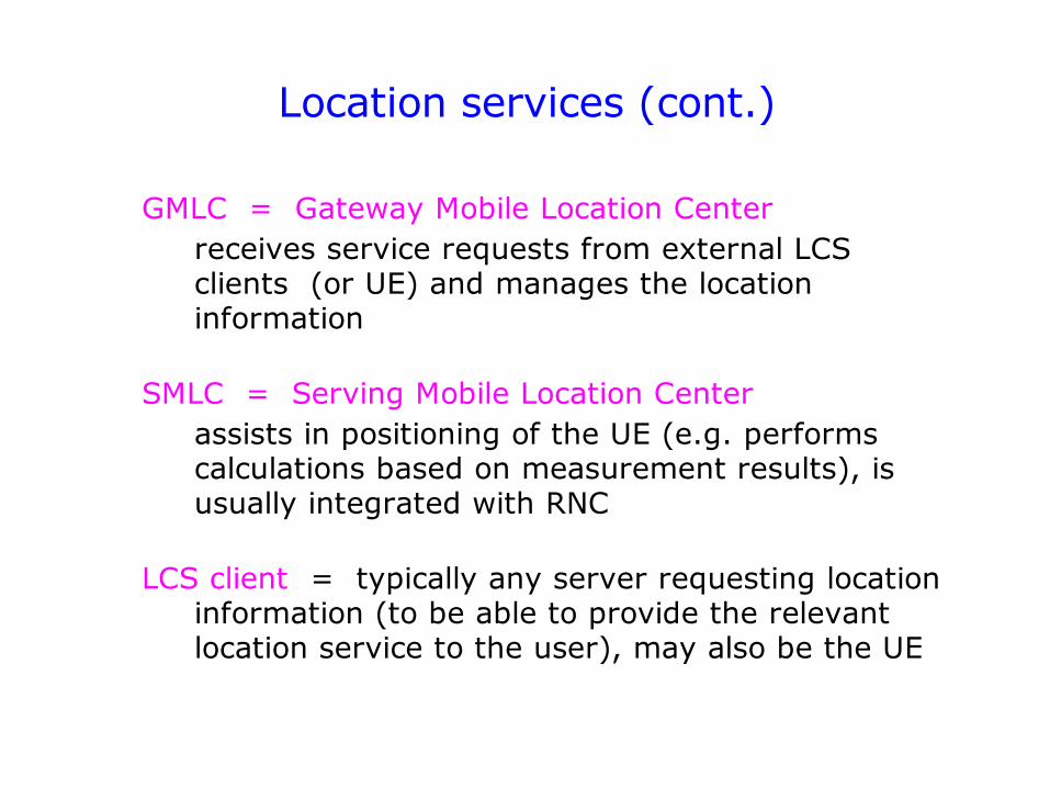
Location services (cont.)
GMLC = Gateway Mobile Location Center receives service requests from external LCS clients (or UE) and manages the location information
SMLC = Serving Mobile Location Centerassists in positioning of the UE (e.g. performs calculations based on measurement results), is usually integrated with RNC
LCS client = typically any server requesting location information (to be able to provide the relevant location service to the user), may also be the UE
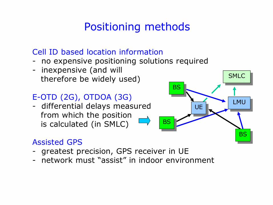
Positioning methods
BS
BS
BS
UELMU
Cell ID based location information- no expensive positioning solutions required- inexpensive (and will therefore be widely used)
E-OTD (2G), OTDOA (3G)- differential delays measured from which the position is calculated (in SMLC)
Assisted GPS- greatest precision, GPS receiver in UE- network must “assist” in indoor environment
SMLC
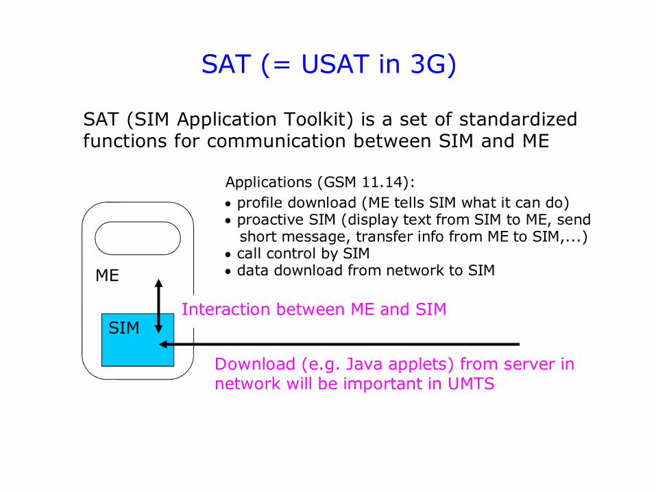
SAT (= USAT in 3G)
SAT (SIM Application Toolkit) is a set of standardized functions for communication between SIM and ME
SIM
ME
Applications (GSM 11.14): profile download (ME tells SIM what it can do) proactive SIM (display text from SIM to ME, send short message, transfer info from ME to SIM,...) call control by SIM data download from network to SIM
Download (e.g. Java applets) from server in network will be important in UMTS
Interaction between ME and SIM
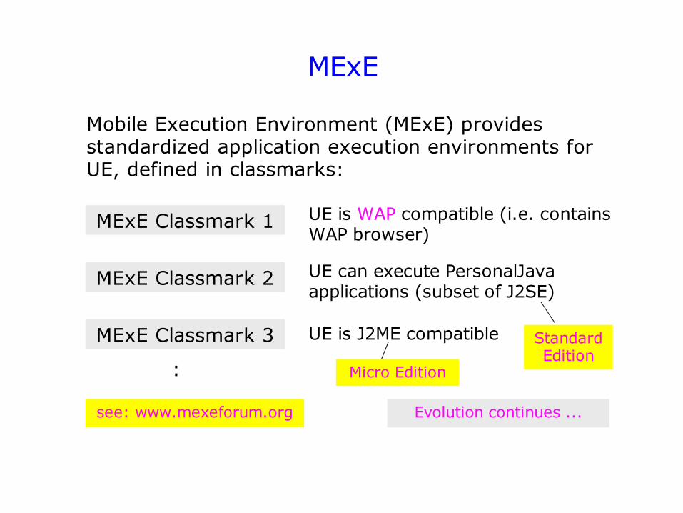
MExE
Mobile Execution Environment (MExE) provides standardized application execution environments for UE, defined in classmarks:
MExE Classmark 1
MExE Classmark 2
MExE Classmark 3
UE is WAP compatible (i.e. contains WAP browser)
UE can execute PersonalJava applications (subset of J2SE)
UE is J2ME compatible Standard Edition
Micro Edition:
see: www.mexeforum.org Evolution continues ...
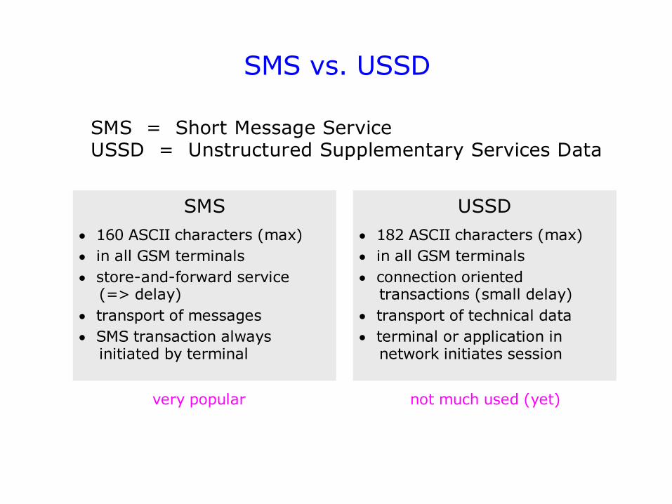
SMS vs. USSD
SMS = Short Message ServiceUSSD = Unstructured Supplementary Services Data
SMS 160 ASCII characters (max) in all GSM terminals store-and-forward service (=> delay) transport of messages SMS transaction always initiated by terminal
USSD 182 ASCII characters (max) in all GSM terminals connection oriented transactions (small delay) transport of technical data terminal or application in network initiates session
very popular not much used (yet)
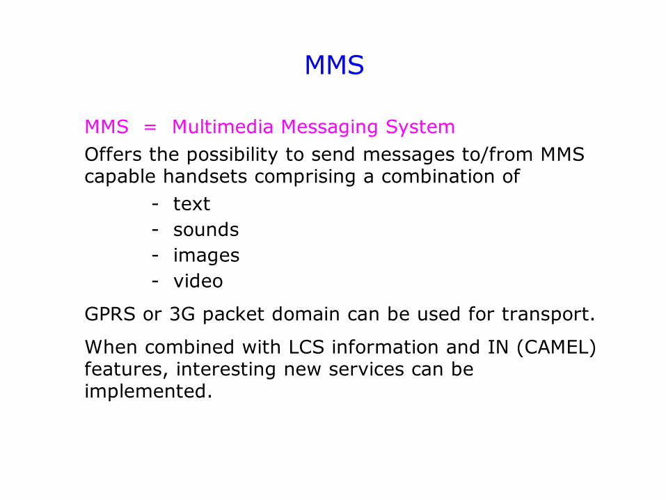
MMS
MMS = Multimedia Messaging System Offers the possibility to send messages to/from MMS capable handsets comprising a combination of
- text - sounds- images - video
GPRS or 3G packet domain can be used for transport.
When combined with LCS information and IN (CAMEL) features, interesting new services can be implemented.
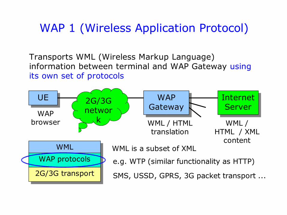
WAP 1 (Wireless Application Protocol)
Transports WML (Wireless Markup Language) information between terminal and WAP Gateway using its own set of protocols
WAP Gateway
UE 2G/3G networ
k
Internet Server
WAP browser WML / HTML
translation
WML
WAP protocols
2G/3G transport
WML is a subset of XML
e.g. WTP (similar functionality as HTTP)
SMS, USSD, GPRS, 3G packet transport ...
WML / HTML / XML
content
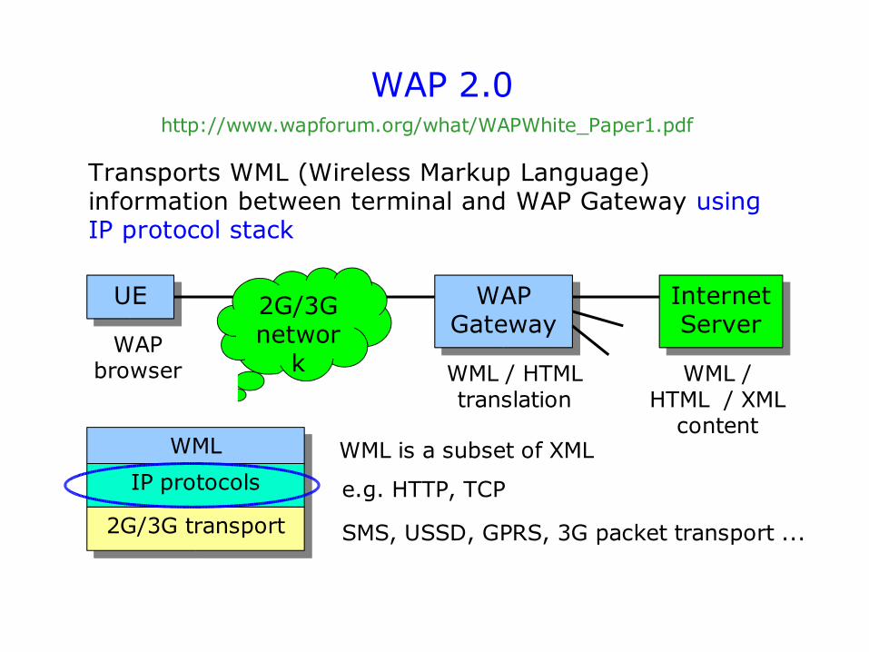
WAP 2.0
Transports WML (Wireless Markup Language) information between terminal and WAP Gateway using IP protocol stack
WAP Gateway
UE 2G/3G networ
k
Internet Server
WAP browser WML / HTML
translation
WML
IP protocols
2G/3G transport
WML is a subset of XML
e.g. HTTP, TCP
SMS, USSD, GPRS, 3G packet transport ...
WML / HTML / XML
content
http://www.wapforum.org/what/WAPWhite_Paper1.pdf
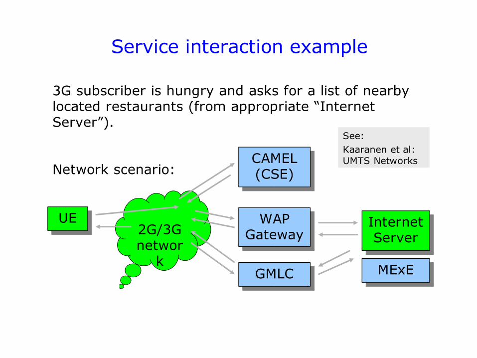
Service interaction example
3G subscriber is hungry and asks for a list of nearby located restaurants (from appropriate “Internet Server”).
Network scenario:
UE2G/3G networ
k
WAP Gateway
Internet Server
CAMEL (CSE)
GMLC MExE
See: Kaaranen et al: UMTS Networks
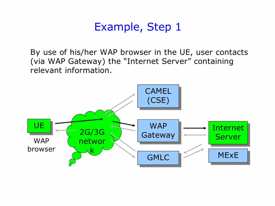
Example, Step 1
By use of his/her WAP browser in the UE, user contacts (via WAP Gateway) the “Internet Server” containing relevant information.
UE2G/3G networ
k
WAP Gateway
Internet Server
CAMEL (CSE)
GMLC MExE
WAP browser
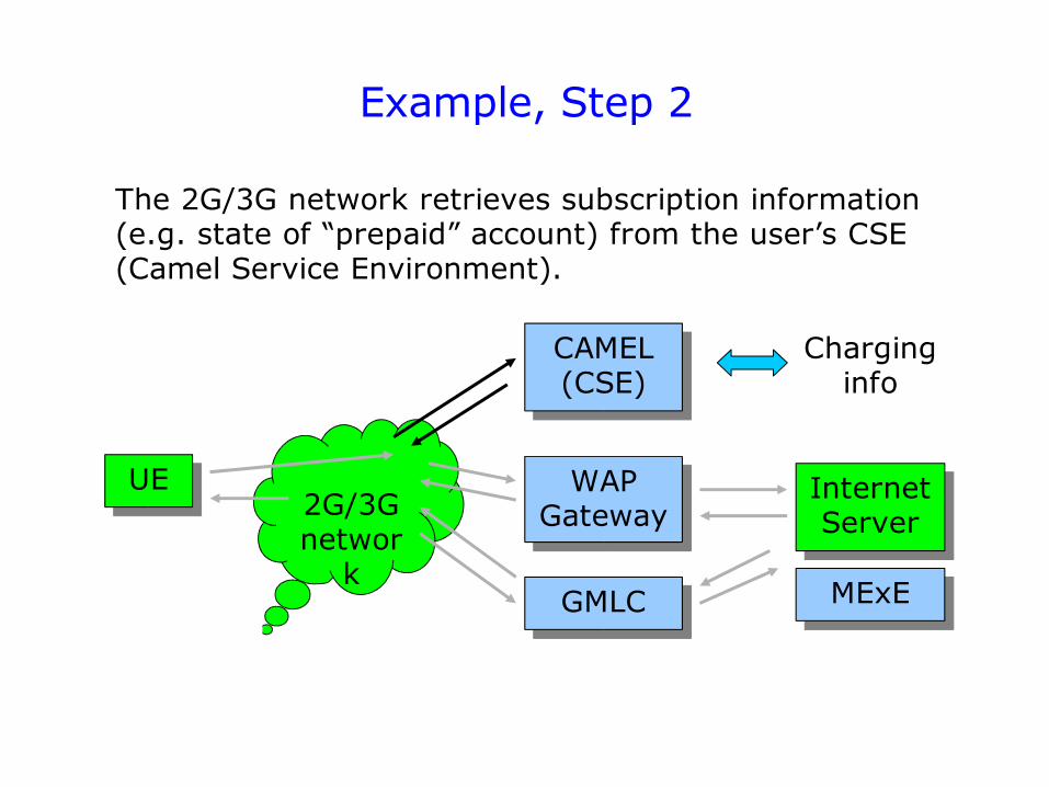
Example, Step 2
The 2G/3G network retrieves subscription information (e.g. state of “prepaid” account) from the user’s CSE (Camel Service Environment).
Charging info
UE2G/3G networ
k
WAP Gateway
Internet Server
CAMEL (CSE)
GMLC MExE
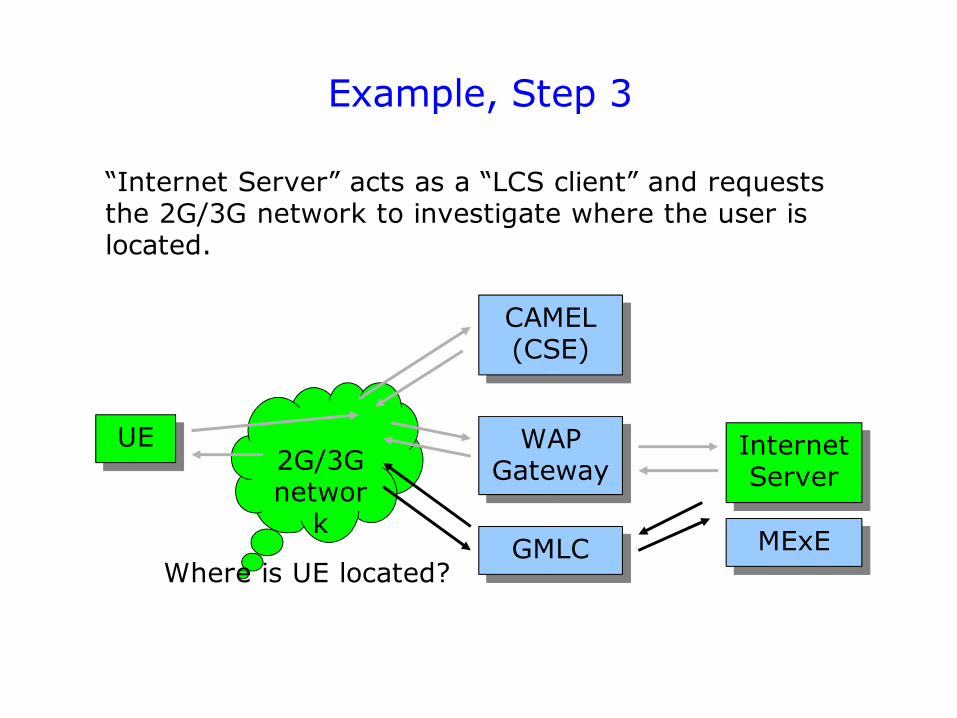
Example, Step 3
“Internet Server” acts as a “LCS client” and requests the 2G/3G network to investigate where the user is located.
UE2G/3G networ
k
WAP Gateway
Internet Server
CAMEL (CSE)
GMLC MExEWhere is UE located?
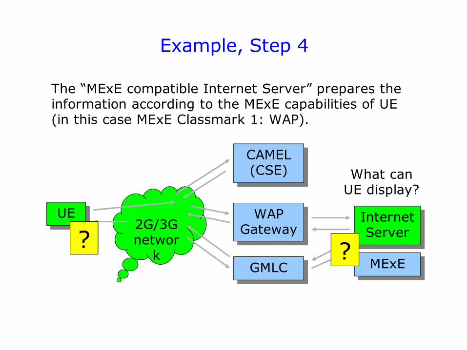
Example, Step 4
The “MExE compatible Internet Server” prepares the information according to the MExE capabilities of UE (in this case MExE Classmark 1: WAP).
What can UE display?
UE2G/3G networ
k
WAP Gateway
Internet Server
CAMEL (CSE)
GMLC MExE??
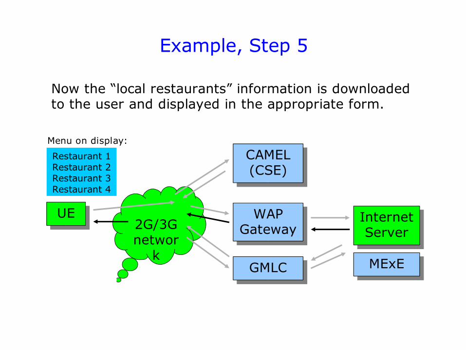
Example, Step 5
Now the “local restaurants” information is downloaded to the user and displayed in the appropriate form.
Restaurant 1Restaurant 2Restaurant 3Restaurant 4
Menu on display:
UE2G/3G networ
k
WAP Gateway
Internet Server
CAMEL (CSE)
GMLC MExE
Further information on 3G systems and services
Links: see slides
Books:
Kaaranen et al., UMTS Networks: Architecture, Mobility and Services, Wiley, 2001, ISBN 0-471-48654-X
Korhonen, Introduction to 3G Mobile Communications, Artech House, 2001, ISBN 1-58053-287-X
Many books on WCDMA technology (i.e. the radio interface) are available. However, understanding of WCDMA basics is not required in this course.