Embed Size (px)
Citation preview
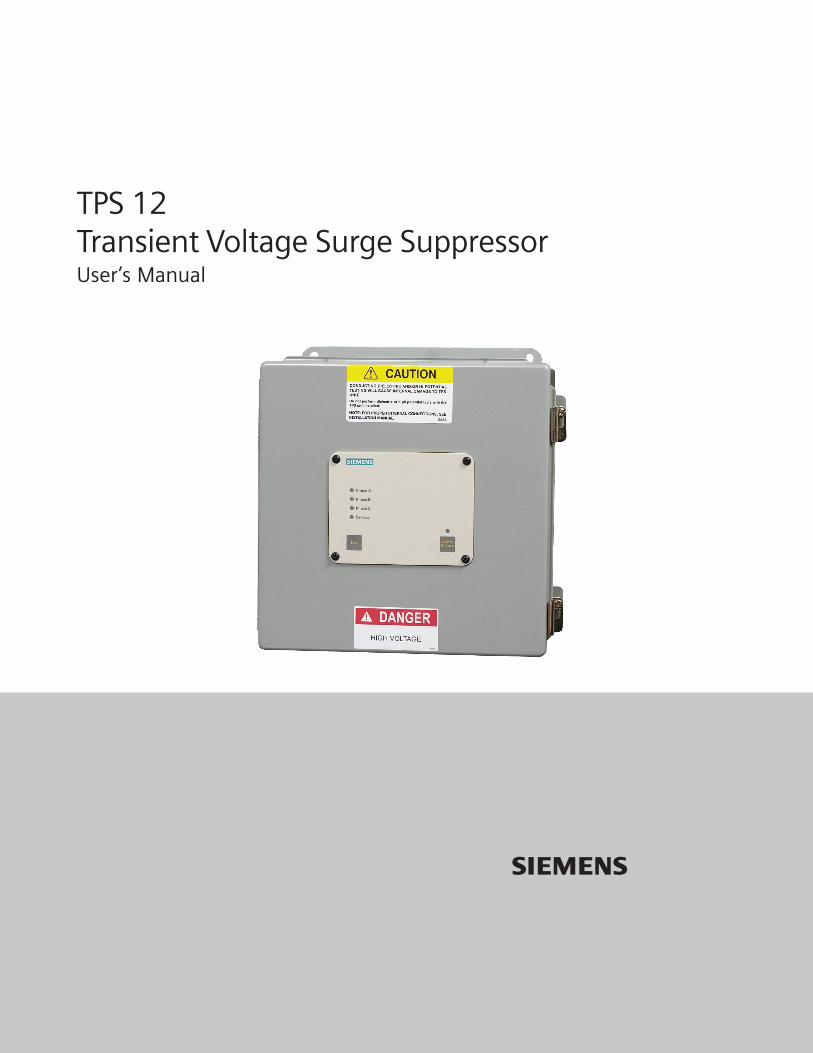
TPS 12Transient Voltage Surge SuppressorUser’s Manual
s


Recommended Application ..................................................................................................... 1Unpacking and Preliminary Inspection .................................................................................... 1Storage .................................................................................................................................... 1Environment ............................................................................................................................ 1Equipment Performance .......................................................................................................... 1
How to Decode a Model Number - Product Orientation .......................................................... 2Service Clearance .................................................................................................................... 2Audible Noise ........................................................................................................................... 2Mounting - Dimensions and Weight ......................................................................................... 2
Overcurrent Protection ............................................................................................................ 3Voltage Rating .......................................................................................................................... 3Terminals ................................................................................................................................. 3Wire Size and Installation Torque ............................................................................................. 3Circuit Breaker and Disconnect Switch .................................................................................... 3SYSTEM GROUNDING .............................................................................................................. 3
Parallel Connections ................................................................................................................ 4Installation Instructions ........................................................................................................... 4Flush Mount Installation Instructions ...................................................................................... 5Installation Wiring Diagrams ................................................................................................... 5
Audible Alarm .......................................................................................................................... 6Surge Counter Options ............................................................................................................ 6Dry Contacts Option ................................................................................................................. 6Touchpad & LED Status Indicators ........................................................................................... 7Disconnect Switch Option ....................................................................................................... 8Remote Monitor Option ........................................................................................................... 8Remote Mointor Installation Instructions ................................................................................ 8
Periodic Inspection and Cleaning ........................................................................................... 10Corrective Maintenance and Repairs ...................................................................................... 10Module Replacement .............................................................................................................. 10
Limited Warranty ..................................................................................................................... 11General Information ............................................................................................................... 11
TABLESTable 1 - Voltage Rating and Service Type................................................................................ 3Table 2 - DB-9 Pin Configuration ............................................................................................... 7
FIGURESFigure 1 - Typical Parallel Connections ..................................................................................... 4Figure 2 - Remote Monitor Wiring Diagrams ............................................................................ 9
Table of Contents

WARNING - - IMPORTANT - - PLEASE READ - - WARNING
INSTALLATION - BONDING AND GROUNDING HAZARD: Verify the neutral conductor in theservice entrance equipment is bonded to ground in accordance with the National Electrical Code and verifythe neutral terminals (XO) on the secondary side of distribution transformers are grounded to the systemground in accordance with NEC and all applicable codes.
During installation into an electrical system, the TPS must not be energized until the electricalsystem is completely installed, inspected and tested. All conductors must be connected andfunctional including the neutral (if required). The voltage rating of the device and system must always beverified before energizing the TPS.
Failure to follow these guidelines can lead to abnormally high voltage at the TPS. This may cause the TPS tobecome inoperative. The warranty is voided if this device is incorrectly installed and/or if neutralconductor in the service entrance equipment is not bonded to ground in accordance with theNational Electrical Code (NEC).
TESTING - HIGH VOLTAGE TESTING - DO NOT HI-POT TEST: Any factory or on-site testing ofpower distribution equipment that exceeds the normal operating voltage such as high-potential insulationtesting, or any other tests where the suppression components will be subjected to voltages higher thantheir rated turn on voltage must be conducted with the suppressor disconnected from the power source.For 4-wire TPS devices, the neutral connection at the TPS must also be disconnected prior to performinghigh-potential testing and then reconnected upon completion of the test.
Failure to disconnect this surge suppression device and its associated suppression components duringelevated voltage testing will damage suppression components and/or other electronic components, andwill void the warranty.
Save this manual! It includes instructions for obtaining warranty service and returning a defective unit.
V WARNING• Confirm XO N-G Bonding at Upstream Transformer• Do Not Hi-Pot Test TVSS• Resulting Damage is not Covered Under Warranty

RECOMMENDED APPLICATION
Siemens Transient Protection System (TPS) is a high quality,high energy surge suppression system that is designed toprotect sensitive equipment from damaging transient over-voltage surges. Proper installation is imperative to maximizethe surge suppressor’s effectiveness and performance. Theinstaller should follow the steps outlined in this manual toinsure a proper installation. Improper installation will void theunit’s warranty. The entire manual should be read prior tobeginning the installation. These instructions are not intendedto replace national or local electrical codes. Check all appli-cable electrical codes to verify compliance. Installation shouldonly be performed by qualified electrical personnel.
The TPS12 Product Line is a single port parallel surge protec-tion device designed for service entrance and downstreampanelboard applications as a stand alone, wall mount unit.The TPS12 Series is available with 120kA, 160kA, or 240kAsurge capacity per phase.
All Siemens TPS products are extensively tested according toindustry standards by IEEE C62.41 and C62.45, for CategoriesA, B, and C. The TPS12 Series is listed to UL 1449 SecondEdition, UL 1283 Fourth Edition Listed, and UL Listed to Cana-dian safety standards. This unit has passed UL 1449 SecondEdition’s most severe fault current test as listed in Section37.3. This unit is qualified for all circuit ampacities.
The TPS12 Series has 200kA UL Listed Short Circuit CurrentRatings (SCCR’s) and are suitable for use on circuits capable ofdelivering not more than 200,000 rms symmetrical amperes.
This device features internal overcurrent and overtemperatureprotection that will disconnect effected surge protection com-ponents at the end of their useful life but will maintain powerto the load - now unprotected. If this situation is undesirablefor the application, follow these instructions for servicing orreplacing the device.
We recommend that the TPS be installed with the shortestand straightest possible lead lengths.
UNPACKING AND PRELIMINARY INSPECTION
Inspect the shipping container for damage or signs of mis-handling before unpacking the unit. Remove the cardboardpacking and inspect for obvious shipping damage.
If any damage is found and is a result of shipping or handling,immediately file a claim with the shipping company and for-ward a copy to either Siemens or your supplier.
Page 1
Hazardous voltage.Will cause death or serious injury.Keep Out.
Qualified personnel only.
Disconnect and lock off all power before
working on this equipment.
STORAGE
The unit should be stored in a clean, dry environment.Storage temperature is -55o C (-67o F) to +65o C (+149o F).Avoid exposing the unit to areas of high condensation. Allpackaging materials should be left intact until the unit is readyfor installation. If the unit has been stored for an extendedperiod of time, inspect unit prior to installing and placing intoservice.
ENVIRONMENT
The standard enclosure unit is designed to operate indoorsin an ambient temperature range of -40o C (-40o F) to +60o C(+140o F) with a relative humidity of 0% to 95% (non-condens-ing). The standard unit is in a NEMA Type 12 industrial useenclosure which is intended for indoor use primarily to pro-vide a degree of protection against contact with the enclosedequipment. It should not be installed in areas with excessivedust, flammable materials, corrosive vapors or explosiveatmospheres. Other NEMA type enclosures are available.
EQUIPMENT PERFORMANCE
To obtain maximum SPD performance, the SPD must belocated as close to the circuit as possible to minimize wirelength.
We recommend that the TPS be installed with the shortestand straightest possible leads, gently twisted together wherepossible.
For optimum transient surge protection, staged surge sup-pression should be implemented at the service entrance andall other electrical connections to the building (telephone,CATV, etc.). Additional surge protection should be installed atrecognized surge generating loads such as arc welding rigs,large motors, switched capacitors, etc. Sensitive electronicloads such as computer equipment, facsimile machines, copymachines, solid state motor drives, variable frequency drives,should also have localized surge suppression. For intercon-nected electronic loads (via data cabling), surge protectivedevices should also be utilized to protect devices on bothends of data cables.

Page 2
Voltage CodeA = 120/240 1∅ 3WB = 240/120V 3∅ 4WC = 208Y/120V 3∅ 4WD = 240V 3∅ 3WE = 480Y/277V 3∅ 4WF = 480V 3∅ 3WG = 600V 3∅ 3WK = 380Y/220V 3∅ 4WL = 600Y/347V 3∅ 4W
OptionsR = Remote MonitorD = Disconnect Switch03 = NEMA 3R Enclosure04 = NEMA 4 Enclosure4X = NEMA 4X EnslosureF = Flush Mount OptionS = Surge Counter Option2 = Dual Surge Counter Option
Surge Current (kA)120160240
Catalog Number: TPS 12
SERVICE CLEARANCE
In addition to national and local code requirements, 36” isrequired at the front of the TPS Series for service clearance.
AUDIBLE NOISE
Unit noise is negligible and does not restrict the location ofthe installation.
MOUNTING, DIMENSIONS AND WEIGHT
The TPS12 Series is designed to be mounted on a vertical wall.Refer to diagram for mounting dimensions and weight.
PRODUCT ORIENTATION
Model number on ID nameplate inside of door can bedecoded as follows:
Date of Manufacture, Short Circuit Current Rating, and UL 1449Suppression Voltage Levels (SVR’s) are also on the unit IDnameplate.
Example: TPSC12240SFDR identifies a TPS12, 208Y/120V,Three Phase, Four Wire, 240kA per phase Surge CurrentRating, with options: Surge Counter, Flush Mount, DisconnectSwitch, and Remote Monitor.
Note: Flush Mount available with NEMA 12 Enclosure Only.Dual Surge Counter available with WYE Voltage Codes Only.
• Mounting Holes are 5/16” (0.8 cm)
• Unit weight 21 lbs. (9.6 kg)
• Flange to Flange measures 11.55” (29.3 cm)
• Optional Enclosure for Disconnect: Add 2 inches (5 cm)
to all dimensions except depth and add 5 lbs. (2.3kg)
MOUNTING, DIMENSIONS AND WEIGHT
VWARNING• Confirm XO N-G Bonding at Upstream Transformer
• Do Not Hi-Pot Test TVSS
• Resulting Damage is not Covered Under Warranty
Note: When no option is selected, a zero (0) is used in option field.
10.36”26.3 cm
8.0”20.3 cm
10.75”27.3 cm
5.0”
12.7 cm
DiagnosticsDisplay Panel
10.36”26.3 cm

OVERCURRENT PROTECTION
The TPS will only conduct upon encountering an overvoltagecondition. TPS’s contain UL registered internal fusing toprotect against abnormal conditions. TPS’s contain internalovertemperature controls.
VOLTAGE RATING
Prior to mounting, verify that the TPS has the same voltagerating as the power distribution system to which it is installed.The specifier or the user should be familiar with the configura-tion and arrangement of the power distribution system inwhich any TPS is installed. The system configuration of anypower distribution system is based strictly on how the sec-ondary windings of the transformer supplying the serviceentrance main or load are configured. This includes whetheror not the transformer windings are referenced to earth via agrounding conductor. The system configuration is not basedon how any specific load or equipment is connected to a par-ticular power distribution system. See Table 1 for the voltagerating and the type of power system configuration of the TPS.
TABLE 1: VOLTAGE RATING AND SERVICE TYPE
TERMINALS
Terminals are provided inside TPS units for line (phase),neutral (if used), and equipment safety ground connections.
WIRING SIZE AND INSTALLATION TORQUE
With a parallel connection, the size of the wiring to the TPSis independent of the ampere rating of the circuit to beprotected. Use #8 AWG wire for phase, neutral and groundconductors. Torque connections to 18 inch pounds.
CIRCUIT BREAKER AND DISCONNECT SWITCH
The TPS12 Series is designed for connection to a 30A to 40Acircuit breaker (40A preferred). The circuit breaker is theintended disconnect switch and provides short circuit protec-tion to the connecting conductors (an integral disconnectswitch is an option as an alternate disconnect means). TheTPS12 Series has internal overload protection elements.A breaker or disconnect is not required as overcurrentprotection.
SYSTEM GROUNDING
On 4-Wire Power Systems, neutral to ground bonding (MainBonding Jumper) should be installed per the NEC. Failure todo so will cause equipment damage and void the warranty.
An equipment grounding conductor must be used on all elec-trical circuits connected to the TPS. For the best performance,use a single point ground system where the service entrancegrounding electrode system is connected to and bonded toall other available electrodes, building steel, metal waterpipes, driven rods, etc. (for reference see: IEEE STD 142-1991).For sensitive electronics and computer systems, it is recom-mended that the ground impedance measurement be as lowas possible. When metallic raceway is used as an additionalgrounding conductor, an insulated grounding conductorshould be run inside the raceway and sized per the NEC.Adequate electrical continuity must be maintained at all race-way connections. Do not use isolating bushings to interrupt ametallic raceway run. A separate isolated ground for the TPSis NOT recommended. Proper equipment connections togrounding system and ground grid continuity should be veri-fied via inspections and testing on a regular basis as part of acomprehensive electrical maintenance program.
Page 3
SEIRES21SPT EGATLOVECIVRES
21ASPT esahPtilpSV021/042
21BSPT ATLED,geL-hgiH,esahPeerhTV021/042
21CSPT EYW,esahPeerhTV021/Y802
21DSPT ATLED,esahPeerhTV042
21ESPT EYW,esahPeerhTV772/Y084
21FSPT ATLED,esahPeerhTV084
21GSPT ATLED,esahPeerhTV006
21KSPT EYW,esahPeerhTV022/Y083
21LSPT EYW,esahPeerhTV743/Y006
VERIFY THAT ALL POWER CIRCUITS AREDEENERGIZED BEFORE MAKING CONNECTIONS
WARNING!All electrical connections should be performed by aqualified (licensed) electrician or technician. All wiring mustcomply with the National Electrical Code (NEC) andapplicable local codes.

PARALLEL CONNECTIONS
NOTE: Safety Ground required for all units. Per UL 1449 Para-graph 1.4, TPS’s are intended for installation on the load sideof the main overcurrent protection. Locate the TPS as close aspossible to the protected circuit to minimize wire length. Thiswill optimize the performance of the TPS. Long wire runs are tobe avoided if the unit is to perform as intended.
To reduce the impedance that the wire displays to surge cur-rents, route the phase, neutral (if used), and ground conduc-tors within the same conduit and should be tightly bundled orgently twisted together to optimize the performance of theunit. Avoid sharp bends in the conductors.
FIGURE 1: TYPICAL PARALLEL CONNECTIONS
Page 4
WARNING: Disconnect all power while installing the TPS.Attempting to install while energized may result in deathor injury. The installation should be performed by quali-fied electrical personnel.
Verify the neutral conductor of the upstream transformeris bonded to ground in accordance with the National Elec-trical Code.
Use an AC voltmeter to check all voltages to ensure thatthe proper unit has been selected.
Remove power from the AC distribution panel.
Mount the TPS on a vertical surface, such as a wall, viathe flanges, as close as possible to the panel being pro-tected. Configure an appropriate hole in the enclosurefor conductor and communication lines. NOTE: If unit hasFlush Mount Option, refer to Flush Mount Option informa-tion following these instructions.
TPS 12 INSTALLATION INSTRUCTIONS
s
1.
2.
3.
4.
5.
Interconnecting Wiring:• Minimize Length• Avoid Sharp Bends• Gently Twist Conductors Together
Open the cover by loosening the two screws. Insure r ib-bon cables attached to the diagnostic faceplate are notmechanically stressed or become unplugged. For unitswith internally mounted diagnostic faceplates, once theTPS cover is removed, remove the four screws in the cor-ners of the faceplate. Remove and store the screws forreassembly since they are non-captive and can fall outduring disassembly and installation. When removing thecover, insure ribbon cables attached to the diagnosticfaceplate are not mechanically stressed or become un-plugged. Do not allow the diagnostic faceplate to hangby the ribbon cables.
Dress the power cables so that the ribbon cables will notbe pinched, crushed or otherwise damaged when theTPS cover is closed. If connecting the Dry Contacts, it maybe effective to install the communication lines prior tothe power conductors.
Twist together and keep as short as possible the connect-ing wires from the TPS to the AC distribution panel.
Connect a #8 AWG wire (in conduit) to the safety groundbus of the AC distribution panel and to the ground lug ofthe TPS. Use a green wire or mark with a green band.Tighten to 18 inch-pounds. Proper grounding is essentialfor safety.
Connect a #8 AWG wire (in conduit) to the NEUTRAL bus ofthe panel and to the neutral lug of the TPS. Use a whitewire or mark with a white band. Tighten to 18 inch-pounds.
Connect a #8 AWG wire (in conduit) to each phase feedon the LOAD side of the circuit breaker in the AC distribu-tion panel. Use a 30A to 40A (40A preferred) circuit breakerwith the appropriate number of poles. Turn the circuitbreaker OFF before making any connection. Refer to theconnection lug phase markings in the TPS and on theappropriate diagrams that follow, when making the phaseconnections.
After all connections have been made but before closingthe circuit breaker, reinstall the internal diagnostic face-plate if it was removed in step 6. Check to insure that allribbon cable connectors are all fully engaged in their sock-ets. Replace the TPS cover and restore power to the ACdistribution panel or circuit breaker as required. If the TPSis installed and functioning properly, the green LED indi-cators on the front diagnostic face plate will be lit andthere will be no audible or visual alarms.
WARNING: HIGH VOLTAGE TESTING - Any factory oron-site testing of power distribution equipment that
6.
7.
8.
9.
10.
11.
12.
13.

exceeds the normal operating voltage such as high-po-tential insulation testing, or any other tests where thesuppression components will be subjected to voltageshigher than their rated turn on voltage must be conductedwith the suppressor disconnected from the power source.For 4-wire TPS devices, the neutral connection at the TPSmust also be disconnected prior to performing high-po-tential testing and then reconnected upon completion ofthe test.
If you have any questions pertaining to the installationinstructions, call Siemens TPS Technical Support at:888-333-3545.
Page 5
MountingHoles
9” 12”
12”
11”
14.
OPTIONAL FLUSH MOUNT INSTALLATION INSTRUCTIONS
The TPS12 unit is approximately 5” deep. The unit will not mountflush unless there is at least 5” of clearance. The TPS12 is notdesigned to mount flush on a typical 2 x 4 stud wall.
Back Flange Mounting: Mount as close as possible to pro-tected panel. Create a wall opening slightly larger than 12”high by 12” wide. See drawing. Configure a robust backingplate inside the wall cavity 6” from the wall face such that theTPS will be supported from its back. Note the mounting holeson the back flange. Also note that the TPS weighs 25lbs. Becareful not to drop the unit into the wall. Configure electricalconductor and conduit connections consistent with Installa-tion Instructions beginning on page 4. Carefully reattachribbon cables and faceplate/cover prior to energizing andtesting unit.
The TPS12 Series is designed for back flange mounting only.Do not attempt to install the TPS such that its weight is sup-ported by the front flange. The four mounting holes on thefront flange are intended to secure the front flange to theouter wall surface.
INSTALLATION WIRING DIAGRAMS
TPSA12: 240/120VAC Split Phase, 3 Wire, plus Ground
C
TPSB12: 240/120VAC 3 Phase (High-Leg) DELTA, 4 Wire, plusGround
VWARNING• Confirm XO N-G Bonding at Upstream Transformer
• Do Not Hi-Pot Test TVSS
• Resulting Damage is not Covered Under Warranty

Page 6
TPSC12, TPSE12, TPSK12, TPSL12: 3 Phase WYE, 4 Wire, plusGround
TPSD12, TPSF12, TPSG12: 3 Phase DELTA, 3 Wire, plus Ground
CONDUCTING DIELECTRIC AND/OR HI-POTENTIALTESTING WILL CAUSE INTERNAL DAMAGE TO
TPS UNIT AND WILL VOID THE UNITS WARRANTYDo not perform dielectric or high potential
tests with the TPS unit installed.
CAUTION
AUDIBLE ALARM
The TPS12 Series device is equipped with an audible alarmwhich will sound in the event of an alarm condition. In addi-tion, the red Service LED will illuminate, indicating that thedevice needs service. Press Alarm Silence to silence thealarm. The red Service LED will remain on even though thealarm is silenced. The Audible Alarm can be tested by press-ing Test. This tests the alarm regardless of the Alarm Silencestatus. Test tests the red Service LED and the Audible Alarm.
The Siemens TPS requires minimal operator intervention afterinstallation. The TPS Series include a diagnostic circuit whichmonitors the suppressor status continually and automatically.
SURGE COUNTER OPTIONS
Surge counter options provide a means to total the number oftransient voltage surges since the counter was last reset. Thesurge counter circuitry includes a supercap. This will providepower up to four days to retain memory should a power outageoccur. Please note: There is a 10-15 minute charging cycle afterfirst energization, before the surge counter(s) operate.
There are two Surge Counter options: a single counter and dualcounters. The single Surge Counter registers the sum of L-N andL-G transient surges. The dual Surge Counters separately registerL-N transients and L-G transients on their respective counters.There are Count and Reset touchpads. Pressing Count incrementsthe counter(s) by one. Pressing Reset resets the counter(s) to zerocount. (Note: Dual surge counter is not available on the DELTA TPSunits which do not have a Neutral.)
DRY CONTACTS OPTION
The TPS12 optional Dry Contacts utilize a DB-9 connector. Thisfeature provides two sets of normally open (N.O.) and nor-mally closed (N.C.) contacts through the DB-9 connector. Theserelay contacts can be used for remote indication of the TPS’operating status. Examples could include a computer inter-face board, an emergency management system, etc. Therelay contact pin arrangement is outlined in Table 2. (Pleasenote the jumpered connections. Pins 7, 8 & 9 do not representa third set of contacts.)
An optional Remote Monitor accessory is available that willprovide visual and audible indication of an alarm condition.The Remote Monitor collects information through the DryContact’s DB-9 connection. Please note that the DB-9 connec-tor is completely utilized by the optional remote monitoringaccessory. If the Remote Monitor is used, there will be no meansto interface with another device.

Page 7
TPS12 CONTROL AND DIAGNOSTIC PANEL
Test:Tests red Service LED and Audible Alarm, and changes stateof Dry Contacts (if equipped).Count:Increments optional surge counter(s) by one (bothcounters, if equipped).Reset:Resets optional surge counter(s) by one (both counters, ifequipped).Alarm Silence:Turns alarm off. (Note that alarm is de-activated when LEDis illuminated)Phase A, B, & C:Tri-color LED Status indicators:Green - Full ProtectionAmber - Partial ProtectionRed - No ProtectionService:LED illuminates for any Amber or Red indication.
For custom applications using Dry Contacts, please note thefollowing information:
• The Dry Contacts are designed for low voltage orcontrol signals only.
• Maximum switching current is 1 amp.
• Maximum switching voltage is 24 volts, DC or AC.
Higher energy application may require additional relay imple-mentation outside the TPS. Damage to the TPS’ relay causedby implementation with energy levels in excess of thosediscussed in this manual will not be covered by warranty.
TABLE 2: DB-9 PIN CONFIGURATION
NIP EPYTTCATNOC
1 )1(desolCyllamroN
2 )1(nommoC
3 )1(nepOyllamroN
7,4 )2(desolCyllamroN
8,5 )2(nommoC
9,6 )2(nepOyllamroN
NOTE: Pin pairs 4 & 7, 5 & 8, and 6 & 9, are connected viajumper internally. The combined current of each pin pair maynot exceed 1 Ampere.
TOUCHPAD & LED STATUS INDICATORS
All indicators and controls are located on the front diagnosticpanel of the TPS unit. Each phase features a tri-color LED indi-cator. Green indicates correct operation. Amber indicatesreduced protection. Red indicates loss of protection. If aninoperative condition were to occur, the built-in audible alarmwill sound and the red Service LED will illuminate. This indi-cates that the unit needs evaluation by a qualified electricianor technician. Until a qualified person evaluates the unit, pressAlarm Silence to silence the alarm. (The LED indicator aboveAlarm Silence illuminates when the alarm is deactivated.Normal operation occurs with the Alarm Silence LED extin-guished.) The red Service LED will remain illuminated eventhough the Audible Alarm has been silenced. Test tests thered Service LED and the Audible Alarm, and changes the stateof Dry Contacts (if equipped).
If LEDs are illuminated in a manner that suggests contradic-tory information, there may be an internal logic problem andthe unit needs replacement. If none of the LEDs are illumi-nated, the unit may not be installed correctly. Please note thatthe internal storage capacitor for surge counter backup mustbe energized for about 15 minutes before Count will function.If a green LED is not illuminated and is suspected of beingfaulty, a qualified electrician or technician may attempt todiagnose the problem by de-energizing the unit, removingthe front cover and exchanging ribbon cable leads withanother phase (if available). Upon reenergizing the TPS, theappropriate LED will illuminate if the suspect LED has failed. Iftroubleshooting indicates a failed LED, please contactSiemens TPS Technical Support at: 888-333-3545.

Page 8
REMOTE MONITOR OPTION
The Remote Monitor option provides operational status for 1-3 TPS up to 1000 feet away. The Remote Monitor requires inputinformation from each SPD’s dry contact.
Connections are made to the Remote Monitor’s 10 positionterminal block using 25 to 18 AWG wire (not provided). TheRemote Monitor includes a 6’ cord connected power supplythat requires a traditional 120VAC wall outlet.
The Remote Monitor’s output has one Green LED, one flashingRed LED, an audible alarm and a Form C dry contact (NO-C-NC).
Upon receiving a status change via the SPD’s dry contacts,the Remote Monitor’s Green LED will go out, the Red LED willflash, the audible alarm will sound, and the Remote Monitor’sdry contact output will change state (i.e.: Normally Open willchange to Closed, and Normally Closed will change to Open).
The Remote Monitor has a three position slide switch for Test,Normal, and Silence. The Test position turns the Green LEDoff, the flashing Red LED on, the audible alarm on, and changesthe state of the output dry contacts. During an alarm condi-tion, the Silence position will silence the audible alarm whilethe Red LED continues to flash. When the anomaly is corrected,reset to the Normal position.
DISCONNECT SWITCH OPTION
The integral disconnect provides a means to de-energize theTPS for service. With disconnect, the box size is 12.36” x 12.36”,without disconnect box size is 10.36” x 10.36”.
REMOTE MONITOR INSTALLATION INSTRUCTIONS
Plan installation. Remote Monitor can be installed on Din-Railor included mounting attachment. Position Remote Monitorappropriately with access to power. Remove four screws toaccess internal circuit board. Note diagram identifying keycomponents. Input wiring diagram identifying several instal-lation options is included. This unit ships with a jumper in-stalled between 2 and 9 for a typical one SPD, Normally Openconfiguration. The jumper can be removed for other configu-rations. (FYI: 9 and 10 are jumpered internally.) Attach powerleads from power supply (not polarity sensitive). If Output DryContacts are used, attach appropriately. Use included tie-wrapsfor cable strain relief. Reassemble unit and mount. Test unit.
VWARNING• Confirm XO N-G Bonding at Upstream Transformer
• Do Not Hi-Pot Test TVSS
• Resulting Damage is not Covered Under Warranty

Page 9
Using Normally Open Contacts Using Normally Closed Contacts
One
TV
SS
Two
TV
SS
Thr
ee T
VS
S
1
2
3
4
5
6
7
8
9
10
Jum
per
TVSS #1 N.O.
TVSS #2 N.O.
TVSS #3 N.O.
1
2
3
4
5
6
7
8
9
10
Jum
per
N.O.
1
2
3
4
5
6
7
8
9
10
Jum
per
TVSS #1 N.O.
TVSS #2 N.O.
1
2
3
4
5
6
7
8
9
10
TVSS #1 N.C.
TVSS #2 N.C.
TVSS #3 N.C.
1
2
3
4
5
6
7
8
9
10
Jumper
TVSS #1 N.C.
TVSS #2 N.C.
1
2
3
4
5
6
7
8
9
10
N.C.
FIGURE 2: REMOTE MONITOR WIRING DIAGRAMS
Pinout Diagram for Dry Contacts of TVSSUsing DB-9 Style Connector: 1 Normally Closed 2 Common 3 Normally Open 4 Normally Closed 5 Common 6 Normally Open 7 Connected to Pin 4 8 Connected to Pin 5 9 Connected to Pin 6
12345
6789
Form C Set #2
Form C Set #1

MAINTENANCE
PERIODIC INSPECTION AND CLEANING
Inspection of the TPS should be performed periodically tomaintain reliable system performance and continued tran-sient voltage surge protection. While it is difficult to establisha preventive maintenance schedule because conditions varyfrom location to location, inspections for trouble utilizing theon-line diagnostics should be performed on a routine basis,weekly or monthly.
Every effort should be made to ensure that the TPS remainsclean and dry. A towel may be used to wipe the exterior of theenclosure. Avoid excess moisture and dry with a towelas appropriate.
CORRECTIVE MAINTENANCE AND REPAIR
Siemens TPS are designed for many years of safe, reliable,trouble free operation. Unfortunately, even the most reliableequipment can become inoperative.
On-line diagnostics are an integral part of the TPS andindicate if service is required. Audible alarms and abnormalillumination of LEDs indicate problems within the TPS and pos-sibly within the electrical system.
TPS’s are an important link in managing power quality issues.Quality TPS’s such as the TPS12 Series are designed and testedto withstand severe duty. However, there are various electri-cal distribution problems that a TPS will not protect against.Should you suspect a TPS problem, a qualified technicianshould first perform an overview of the electrical distributionsystem including verification of proper voltages and phasing.Regardless of the cause, TPS’s will sacrifice themselves whileattempting to protect their load. Accordingly, a failed TPS mayindicate other problems, as its failure is the effect rather thanthe cause.
MODULE REPLACEMENT
The TPS12 features a replaceable module. In the unlikely eventthat a unit becomes suspect or inoperative, replacing themodule is the most effective solution. Instructions anddiagram to follow.
1. Disconnect the power and confirm that the unit isdeenergized with an AC voltmeter.
2. Identify and/or mark all ribbon cables and conductors toaid in re-assembly.
3. Carefully disconnect the ribbon cables and conductors.4. Remove the four 7/16” nuts attaching the module to the
enclosure. Remove the module.5. Reassembly is opposite of above. Ensure that the green
ground wire is reattached. Secure door before reenergiz-ing the unit.
Should you encounter an unusual problem, or require factoryservice support, please contact Siemens TPS TechnicalSupport at: 888-333-3545.
Page 10
Module attaching nuts

NOTE: Installing a TVSS/SPD on a distribution system withoutNEC compliant N-G bonding, or on any ungrounded distribu-tion system, will result in TVSS/SPD damage. Proper N-G bondsestablish the distribution systems reference to ground. With-out reference to ground, L-G voltages can rise, while L-N volt-ages remain normal. Suppression elements inside TVSS/SPDswill attempt to control the overvoltage. This is a steady-statecondition, not a transient condition, and may damage theTVSS/SPD. This TVSS/SPD includes thermal cutout protection.The activation of any thermal cutout signifies a sustained ov-ervoltage condition in excess of 115% of normal operatingvoltages, i.e., a distribution system problem. Operation of ther-mal cutouts can be verified at the factory and is not a defect inworkmanship or material.
LIMITED WARRANTY
Siemens warrants it’s AC Panel protection products againstdefective workmanship and materials for 5 years. Liability islimited to the replacement of the defective product. A ReturnMaterial Authorization (RA #) must be given by the companyprior to the return of any product. Returned products must besent to the factory with the transportation charges prepaid. Inaddition, the company also warranties unlimited replacementof modular and component parts within the warranty periodpreviously described.
The company specifically disclaims all other warranties,expressed or implied. Additionally, the company will not beresponsible for incidental or consequential damages resultingfrom any defect in any product or component thereof.
TECHNICAL SUPPORT
1.888.333.3545
Prior to calling Siemens TPS Technical Support for assistanceor ordering parts, please have the following informationavailable:
TPS model number: ________________________________
TPS serial number: ________________________________
Manufacture date: _________________________________
Date of Purchase: ___________________________________
Your order number: _______________________________
Optional features purchased with the TPS:
Flush Mount “F”Surge Counter “S”Dual Surge Counter “2”Disconnect “D”Remote Monitor “R”NEMA 3R Enclosure “03”NEMA 4 Enclosure “04”NEMA 4X Enclosure “4X”
YesYesYesYesYesYesYesYes
NoNoNoNoNoNoNoNo
Page 11
VWARNING• Confirm XO N-G Bonding at Upstream Transformer
• Do Not Hi-Pot Test TVSS
• Resulting Damage is not Covered Under Warranty
Return Shipment Address:
Siemens - Attn: RA #___________14550 58th Street NorthClearwater, FL 33760

Siemens Energy & Automation, Inc.Power Distribution Infrastructure Division333 Old Milton ParkwayAlpharetta, GA 30005
1-800-964-4114 ext. [email protected]
© 2005 Siemens Energy & Automation, Inc. All Rights ReservedSiemens is a registered trademark of Siemens AG. Product names mentioned may be trademarks orregistered trademarks of their respective companies. Specifications are subject to change without notice.
Order #PBOM-00108-0508 Rev2 2.5M100DW Printed in U.S.A.